JP2004227127A - Program having a plurality of environment information and information processing apparatus having the program - Google Patents
Program having a plurality of environment information and information processing apparatus having the programDownload PDFInfo
- Publication number
- JP2004227127A JP2004227127AJP2003011965AJP2003011965AJP2004227127AJP 2004227127 AJP2004227127 AJP 2004227127AJP 2003011965 AJP2003011965 AJP 2003011965AJP 2003011965 AJP2003011965 AJP 2003011965AJP 2004227127 AJP2004227127 AJP 2004227127A
- Authority
- JP
- Japan
- Prior art keywords
- program
- information
- environment information
- company
- application program
- Prior art date
- Legal status (The legal status is an assumption and is not a legal conclusion. Google has not performed a legal analysis and makes no representation as to the accuracy of the status listed.)
- Granted
Links
Images


Classifications
- H—ELECTRICITY
- H04—ELECTRIC COMMUNICATION TECHNIQUE
- H04L—TRANSMISSION OF DIGITAL INFORMATION, e.g. TELEGRAPHIC COMMUNICATION
- H04L67/00—Network arrangements or protocols for supporting network services or applications
- H04L67/01—Protocols
- H04L67/10—Protocols in which an application is distributed across nodes in the network
- H04L67/1097—Protocols in which an application is distributed across nodes in the network for distributed storage of data in networks, e.g. transport arrangements for network file system [NFS], storage area networks [SAN] or network attached storage [NAS]
- H—ELECTRICITY
- H04—ELECTRIC COMMUNICATION TECHNIQUE
- H04L—TRANSMISSION OF DIGITAL INFORMATION, e.g. TELEGRAPHIC COMMUNICATION
- H04L9/00—Cryptographic mechanisms or cryptographic arrangements for secret or secure communications; Network security protocols
- H04L9/40—Network security protocols
- H—ELECTRICITY
- H04—ELECTRIC COMMUNICATION TECHNIQUE
- H04L—TRANSMISSION OF DIGITAL INFORMATION, e.g. TELEGRAPHIC COMMUNICATION
- H04L69/00—Network arrangements, protocols or services independent of the application payload and not provided for in the other groups of this subclass
- H04L69/30—Definitions, standards or architectural aspects of layered protocol stacks
- H04L69/32—Architecture of open systems interconnection [OSI] 7-layer type protocol stacks, e.g. the interfaces between the data link level and the physical level
- H04L69/322—Intralayer communication protocols among peer entities or protocol data unit [PDU] definitions
- H04L69/329—Intralayer communication protocols among peer entities or protocol data unit [PDU] definitions in the application layer [OSI layer 7]
Landscapes
- Engineering & Computer Science (AREA)
- Computer Networks & Wireless Communication (AREA)
- Signal Processing (AREA)
- Computer Security & Cryptography (AREA)
- Storage Device Security (AREA)
- Information Retrieval, Db Structures And Fs Structures Therefor (AREA)
Abstract
Translated fromJapaneseDescription
Translated fromJapanese【0001】
【発明の属する技術分野】
本発明はネットワーク接続型ストレージ、サーバシステムおよびオペレーティングシステムに関する。
【0002】
【従来の技術】
企業がインターネットを利用したサービスを提供する際、インターネットの接続設備や、コンピュータシステムを構築するコストを削減するため、データセンタが提供するサービスを利用することがある。
【0003】
データセンタ業者は、インターネットの接続設備を持ち、インターネットを利用したサービスを提供したい企業(顧客)のサーバ設置スペースや、サーバ装置の貸し出しを行っている。通常、顧客に貸し出すストレージは、顧客間のセキュリティを保持するため、個別の装置を割り当てることが多い。
【0004】
しかし、顧客毎に装置を割り当てる方法では、顧客の需要の変化に応じて柔軟に貸し出すストレージの容量を変更することが困難であるとともに、装置が故障した場合に備え、全ての装置を監視する必要があり、装置数が増えることによる管理コストの増大が問題となる。
【0005】
大容量ストレージ装置を論理的に分割し、論理ボリュームとして、顧客のサーバ装置と大容量ストレージ装置をSAN(Storage Area Network)で接続することにより、ストレージ管理を集中化することができ、管理コストを削減することが可能である。しかし、現在、SANで主流となっているファイバーチャネル(Fiber Channel)インタフェースは高価であること、また、顧客は設置スペースに応じた金額で契約しているため、顧客のサーバ装置にインタフェースを追加するスペースが余っていない等の問題がある。
【0006】
NAS(Network Attached Storage)装置は、NFSサービスや、CIFSサービスを利用し、NAS装置に内蔵、もしくは、SCSIや、ファイバーチャネル等ストレージインタフェースを介して接続されたストレージ上に作成したファイルシステムによって、ネットワークを介して他の情報処理装置にファイルを格納することや共有利用することを可能にする。NAS装置は、指定したディレクトリ以下のファイルシステムを公開することができ、複数のディレクトリを公開するよう設定することができる。
【0007】
データセンタでは、インターネット接続を目的としているため、ほとんど全ての顧客サーバはネットワークインタフェースを備えている。NAS装置は、顧客サーバにハードウェアの追加なしで、複数の顧客に対してストレージ・サービスを提供することができる。しかし、NAS装置は、汎用OS(オペレーティングシステム)を利用するケースが多く、悪意のあるユーザによるハッキングや、ウイルスなどによるファイル改竄、ファイル消去等により被害を受けることがある。複数の顧客でNAS装置を共有する場合、これらの被害は同一NAS装置を共有する全ての顧客に及ぶ可能性がある。
【0008】
ネットワークアプライアンス(Network Appliance)社のNAS装置にはMultiStore(非特許文献1)がある。これによれば、一つの装置の上に複数のvfilerと呼ぶ一つ以上のIPアドレスとvolumeを持つCIFSサービス、NFSサービス等の仮想サーバを提供することができる。顧客毎にvfilerを割り当てることにより、顧客毎のユーザ管理や、個別の設定が可能になる。
【0009】
vfilerは、顧客にrshプロトコルを利用したコマンドの実行を可能にしており、NFSサービスの設定変更などが可能であるが、NAS装置に接続したバックアップ装置を使用することはできない。NAS装置に接続したバックアップ装置を使用するためには、装置全体を管理する装置によることが必要である。
【0010】
また、仮想計算機を利用することで、顧客毎に独立したOSを割り当て、サービスを提供するシステムが特許文献1に開示されている。特許文献1記載の技術では、一つの計算機上で複数のOSが動作し、OS毎に独立の資源、たとえば主記憶、ネットワークアダプタ等を割り当てられる。OS間で資源を共有しないため、顧客毎のユーザ管理や、個別の設定等が容易に可能となる。さらに、バックアップ装置の資源割り当てを行うことでバックアップなどにも利用できる。
【0011】
【特許文献1】
特開2002‐024192号公報
【非特許文献1】
“データオンタップ6.2マルチストアアドレスミニストレーションガイド(Data ONTAP 6.2 MultiStore Administration Guide)筈ネットワークアプライアンス社(Network Appliance, Inc.)、[平成14年11月28日検索]、インターネット、<URL:https://now.netapp.com/nowsmforms/login.fcc>にアクセスしてユーザ名とパスワードを入力した後<URL:http://now.netapp.com/NOW/knowledge/docs/ontap/rel62/pdfs/vfiler.pdf>にアクセスすることで入手可能。
【0012】
【発明が解決しようとする課題】
このように、データセンタ業者がインターネットを利用したサービスを提供したい企業(顧客)に対して、セキュリティを確保し、且つ、需要の変化に応じて貸し出すストレージの容量を変更することを可能にするには、従来システムの選択のみでは一長一短がある。例えば、複数の顧客で汎用OSを用いたNAS装置を共有する方法では、1顧客のセキュリティホールによって、NAS装置がハッキングされた場合、NAS装置上では顧客毎のリソースが隔離されていないため、NAS装置を共有する全顧客に対して被害が及ぶ可能性がある。NAS装置でNAS装置に接続したバックアップ装置を利用し、バックアップを取る場合、NAS装置のファイル共有サービスを利用するデータベースなどのアプリケーションをバックアップモードにする等、ディスク上のデータが整合性を保てる状態にする顧客サーバの操作と、バックアップ装置にデータを転送するバックアップ動作を連動させる必要があり、運用が煩雑である。
【0013】
MultiStoreの方法では、テープ装置などの管理権限が顧客側にないため、顧客側の操作だけでバックアップを採取できない。vfilerでは、顧客に与える管理権限の範囲を柔軟に変更することができない。顧客に管理権限を与えると、たとえば、テープ装置からデータをリストアする場合、顧客側の操作ミスによって他の顧客のディスク領域へデータを展開し、他の顧客に損害を与えてしまうことが考えられる。また、他の顧客のデータ覗き見等、顧客間のセキュリティ問題が発生してしまう。
【0014】
また、仮想計算機を利用する方法では、各仮想計算機にあらゆる資源を割り当てるが、仮想計算機の稼働状況によって資源割り当ての不均衡が生じ得る。たとえば、ディスク上のデータを主記憶上にキャッシュし、ファイルアクセスを高速化するためのキャッシュ領域は、仮想計算機毎に独立であり、負荷が低い仮想計算機でキャッシュ領域が余っていても、負荷が高い仮想計算機のキャッシュ領域に充当することはできない。これは、主記憶の割り当て変更等は容易ではなく、たとえば仮想計算機の再起動等が必要となるためである。
【0015】
【課題を解決するための手段】
本発明は、IPアドレスやvolumeだけでなく、物理・論理デバイスのアクセス権を個別に許可、あるいは、制限でき、より運用管理の自由度を高めた仮想的なサーバとして働くデータセンタが実現できる。仮想的なサーバからアクセスできる物理デバイスあるいは論理デバイスを制限することで、顧客からの不正なアクセスによる影響を排除し、運用管理に必要な管理権限を顧客に柔軟に与えることを可能にする。
【0016】
具体的には、OSに顧客側に与える管理権をきめ細かく設定する機能と、顧客の操作が顧客側に与えた管理権の範囲を越えないよう制限する機能を組み込む。具体的には、OSが管理しているプロセス情報に、該プロセス情報が指すアプリケーションプログラムの実行のための環境情報を追加するとともに、この環境情報を新たに生成されるプロセス情報にも継承させる。これにより、顧客が実行するアプリケーションプログラムのすべてのプロセス情報に、環境情報が付与される。環境情報にはアクセス可能な物理デバイスあるいは論理デバイス、アクセス可能なネットワークI/F(インタフェース)、ネットワークのルーティングテーブル、プロトコルテーブル、ファイルシステムのマウントテーブル、および、当該環境情報に属するプロセス情報リストを含める。
【0017】
データセンタの管理者には、指定した環境情報を持つプロセス情報を生成する機能、および、環境情報を変更する機能を提供する。
【0018】
さらに、顧客側の操作だけでテープにバックアップが採取できない課題を解決するため、前述のOS上で、環境情報の一つとして、あらかじめ、テープ装置の管理権限を顧客に与えておくこと、および、データセンタの管理者が環境情報を変更する機能を用い、必要な時にテープ装置の管理権限を顧客に与えることである。
【0019】
本発明では、共有資源を一括管理する単一のOS上で顧客毎の仮想的なサーバ機能を実現するから、OSが一括管理する資源は、プロセス情報が指すどのアプリケーションプログラムからの要求に対しても同等に利用されるため、負荷に応じて資源が有効に活用でき、仮想計算機における負荷の不均衡の問題は生じない。
【0020】
【発明の実施の形態】
(実施の形態1)
以下、本発明の実施の形態1を、図1から図13を用い詳細に説明する。まず、本発明に関わる構成要素の概要を述べ、次に、処理手順とデータ構造の詳細を述べる。
【0021】
図1は、本発明を適用して効果のあるシステムの一例を示す図である。100はデータセンタである。データセンタ100には情報処理装置101が設けられ、データセンタ管理者用PC147、顧客A社のWebサーバ148および顧客B社のWebサーバ149が、それぞれ、管理LAN141、A社LAN142およびB社LAN143を介して接続される。また、A社LAN142およびB社LAN143はファイアウオールA144およびファイアウオールB145を介してインターネット146に接続される。情報処理装置101にはバス113が設けられ、これにCPU111、メモリ112、管理ネットワークI/F121、A社ネットワークI/F122、B社ネットワークI/F123およびストレージI/F131が接続されている。ここで、CPU111は、プロセス情報が指すアプリケーションプログラムを実行することは勿論であるが、後述するように、OSの各種の処理部の処理プログラムを実行して環境情報を生成、管理する。
【0022】
管理ネットワークI/F121には、前述した管理LAN141が、A社ネットワークI/F122には、前述したA社LAN142が、B社ネットワークI/F123には、前述したB社LAN143が、それぞれ、接続される。管理LAN141は、データセンタの管理用のLANであり、これに接続されたデータセンタ管理者用PC147によって管理者が情報処理装置101を管理する。A社LAN142は、データセンタのストレージ・サービスを利用する顧客A社用のLANで、A社Webサーバ148と、ファイアウオールA144が接続されている。B社LAN143は、データセンタのストレージ・サービスを利用する顧客B社用のLANで、B社Webサーバ149と、ファイアウオールB145が接続されている。
【0023】
ストレージI/F131は、第1ハードディスク151、第2ハードディスク152、第3ハードディスク153(以下、ハードディスクはディスクと略称する)およびテープ装置154が接続されている。第1ディスク151は情報処理装置101の管理用に使用されるデータおよび必要なプログラムが格納される。第2ディスク152および第3ディスク153は、適当な論理ボリューム構成とされて、それぞれ、A社およびB社のWebサービスを提供するためのデータ格納用に使用する。テープ装置154はA社およびB社がデータのバックアップ時に使用する。第2ディスク152および第3ディスク153をA社およびB社に割り当てるときは、適当な論理ボリューム構成とするのが運用上有利であるが、以下の説明では、説明を簡便にするため、A社およびB社にそれぞれ第2ディスク152および第3ディスク153を割り当てるものとした。
【0024】
データセンタ100は、インターネット146を介して外部からアクセスされる。161および162はA社およびB社管理者用PCである。A社およびB社管理者は、Webサービスの内容を修正し、あるいは、Webサービスの利用状況などのデータをバックアップとしてテープに格納する必要があるときは、A社およびB社管理者用PC161,162を使用してA社Webサーバ148およびB社Webサーバ149にアクセスする。さらに、インターネット146に接続された一般ユーザ163−165がA社Webサーバ148およびB社Webサーバ149にアクセスしてWebサービスを利用する。
【0025】
データセンタ100は、したがって、顧客の運用管理の自由度を大きくできるようにする一方で、顧客あるいは一般ユーザからの不正なアクセスによる影響を排除できることが重要である。
【0026】
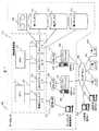
図2は、情報処理装置101上で稼働する主要なプログラム、情報およびこれらの関連を示す図である。
【0027】
情報処理装置101のメモリ112には、アプリケーションプログラムとして、装置管理プログラム201、A社用管理プログラム202、A社用ファイルサーバプログラム203、B社用管理プログラム204およびB社用ファイルサーバプログラム205が実装されている。これらは第1ディスク151に格納されていて、必要によりメモリ112に展開される。
【0028】
装置管理プログラム201は情報処理装置101上で稼働するアプリケーションプログラムであり、データセンタ管理者用PC147と通信し、A社用管理プログラム202の起動、B社用管理プログラム204の起動、および、A社環境情報232やB社環境情報233に対してテープ装置154のアクセス許可の変更などを行う。
【0029】
A社用管理プログラム202は、A社用ファイルサーバプログラム203が稼働する設定を行い、A社用ファイルサーバプログラム203を起動するとともに、A社管理者がA社管理者用PC161からアクセスしてログインするA社Webサーバ148と通信し、A社用ファイルサーバプログラム203の停止、再開、および、テープ装置154に対するデータのバックアップなどを行う。
【0030】
A社用ファイルサーバプログラム203は、A社Webサーバ148が要求するファイルアクセス要求を受付け、OS(オペレーティングシステム)210が提供するファイルシステム処理部214を利用し、第2ディスク152に対してファイルの書き込みや、読み出しを行い、結果をA社Webサーバ148に返す。
【0031】
B社用管理プログラム204およびB社用ファイルサーバプログラム205の動作は、A社用管理プログラム202およびA社用ファイルサーバプログラム203の動作と同様である。
【0032】
OS210には、各種の情報が格納され、この情報に基づいて、情報処理装置101上で稼働し、前述したアプリケーションプログラム201〜205に様々なインタフェースを提供し、プロセス情報の制御やI/O処理、ファイルシステムサービスなどを提供する。
【0033】
格納される情報としては、前述した各アプリケーションプログラムに実行実体であるCPU111の割り当てに必要な第1プロセス情報221、第2プロセス情報222、−−−、第5プロセス情報225と、これらの情報に基づいて、各種のアプリケーションプログラムが実行されるときにアクセス可能なデバイスなどの許可および制限情報である管理環境情報231、A社環境情報232およびB社環境情報233と、さらには、管理ネットワークI/F121、A社ネットワークI/F122およびB社ネットワークI/F123ごとの管理情報である管理ネットワークI/F情報241、A社ネットワークI/F情報242およびB社ネットワークI/F情報243とがある。
【0034】
OS210には、さらに、各種の処理部が格納される。ここで処理部とはOSの機能を果たすためのプログラムであり、これらには以下のものがある。プロセス情報生成時に呼び出されるプロセス情報生成処理部211、プロセス情報が指すアプリケーションプログラムに対して停止、終了、再開等の制御を行うプロセス情報制御処理部217、プロセス情報が指すアプリケーションプログラムにアクセス可能なデバイスなどを許可および制限する情報を変更する時に呼び出される環境情報変更処理部212、デバイスなどへのアクセスの際、その正当性をチェックする許可デバイス判定処理部213、ファイルシステムサービスを提供するファイルシステム処理部214、ストレージI/F131に接続される第1ディスク151、第2ディスク152、第3ディスク153およびテープ装置154への入出力を行うストレージI/O処理部215およびネットワークI/F121、ネットワークI/F122およびネットワークI/F123を介して通信を行う管理ネットワークI/F処理部216である。
【0035】
第1プロセス情報221は、装置管理プログラム201を指すプロセス情報であり、装置管理プログラム201の動作を管理するための情報である。第1プロセス情報221は管理環境情報231に属し、この情報に基づいてアクセス可能なデバイスの制限を受ける。
【0036】
第2プロセス情報222は、A社用管理プログラム202を指すプロセス情報であり、A社用管理プログラム202の動作を管理するための情報である。第3プロセス情報223は、A社用ファイルサーバプログラム203を指すプロセス情報であり、A社用ファイルサーバプログラム203の動作を管理するための情報である。第2プロセス情報222および第3プロセス情報223は、A社環境情報232に属し、この情報に基づいてアクセス可能なデバイスの制限を受ける。
【0037】
第4プロセス情報224は、B社用管理プログラム204を指すプロセス情報であり、B社用管理プログラム204の動作を管理するための情報である。第5プロセス情報225は、B社用ファイルサーバプログラム205を指すプロセス情報であり、B社用ファイルサーバプログラム205の動作を管理するための情報である。第4プロセス情報224および第5プロセス情報225は、B社環境情報233に属し、この情報に基づいてアクセス可能なデバイスの制限を受ける。
【0038】
管理環境情報231は、図2では分離して表現されているが、第1プロセス情報221および管理ネットワークI/F121に対応する管理ネットワークI/F情報241を統合したものとなされる。この管理環境情報231は、装置管理を行うため、データセンタ管理者のみが管理者用PC147から管理LAN141を介してアクセスすることができ、すべてのデバイスに対するアクセス権を管理するための情報を保持するように管理される。
【0039】
A社環境情報232は、図2では分離して表現されているが、第2プロセス情報222、第3プロセス情報223およびA社ネットワークI/F122に対応する管理情報を格納するA社ネットワークI/F情報242を統合したものとなされる。このA社環境情報232は、A社のファイルサーバプログラム203の稼働環境情報を提供するため、データセンタ100とA社との契約によりA社に許可される第2ディスク152、A社ネットワークI/F122のデバイスへのアクセス権を管理するための情報を保持するようにデータセンタ管理者用PC147により管理される。A社管理者によるA社管理者用PC161からA社LAN142を介してのテープ装置154へのアクセス権は、契約により所定の時間のみ与えられる。
【0040】
B社環境情報233は、図2では分離して表現されているが、第4プロセス情報224、第5プロセス情報225およびB社ネットワークI/F123に対応する管理情報を格納するB社ネットワークI/F情報243を統合したものとなされる。このB社環境情報233は、B社のファイルサーバプログラム205の稼働環境情報を提供するため、データセンタ100とB社との契約によりB社に許可される第3ディスク153、B社ネットワークI/F123のデバイスへのアクセス権を管理するための情報を保持するようにデータセンタ管理者用PC147により管理される。B社管理者によるB社管理者用PC162からB社LAN143を介してのテープ装置154へのアクセス権は、契約により所定の時間のみ与えられる。
【0041】
管理ネットワークI/F情報241、A社ネットワークI/F情報242およびB社ネットワークI/F情報243は、それぞれ、管理ネットワーク121、A社ネットワーク122およびB社ネットワーク123に対応し、各ネットワークインタフェースの管理情報である。また、ネットワークI/Fが属する環境情報のポインタを格納しており,受信したデータを格納する環境情報を一意に決定することができる。管理ネットワークI/F情報241、A社ネットワークI/F情報242およびB社ネットワークI/F情報243は、情報としては独立したものであるが、上述したように、管理環境情報231、A社環境情報232およびB社環境情報233と一体として扱われる。
【0042】
プロセス情報生成処理部211は、装置管理プログラム201、A社用管理プログラム202およびB社用管理プログラム204により呼び出されるプログラムである。プロセス情報生成処理部211は、これを呼び出したアプリケーションプログラムと同じ環境情報に属するプロセス情報を生成する機能を有する。これに加え、環境情報を指定することで、新たな環境情報を生成し、その環境情報に属するプロセス情報を生成する機能も有する。ただし、新たな環境情報を生成する機能は、管理環境情報231に属する装置管理プログラム201の実行でのみ可能である。すなわち、管理者権限をデータセンタ管理者のみに与える。
【0043】
プロセス情報制御処理部217は、プロセス情報が指すアプリケーションプログラムに対して停止、終了、再開等の制御を行うことができる。この機能は、管理環境情報231に属する第1プロセス情報221が指す装置管理プログラム201からは全てのアプリケーションプログラムに対して制御することができるが、管理環境情報231以外に属するプロセス情報が指すアプリケーションプログラム(A社環境情報232およびB社環境情報233に属する第2プロセス情報222から第5プロセス情報225が指すプログラム)からは、同一環境情報に属するアプリケーションプログラムに対してのみ制御することができる。
【0044】
環境情報変更処理部212は、指定した環境情報に対してデバイスのアクセスの許可・禁止を設定、変更することができる。この機能は、管理環境情報231に属する第1プロセス情報221が指す装置管理プログラム201のみが実行可能である。すなわち、管理者権限をデータセンタ管理者のみに与える。
【0045】
許可デバイス判定処理部213は、アプリケーションプログラムからデバイスへのアクセスが要求されたとき、アクセスを要求したアプリケーションプログラムを指すプロセス情報が属する環境情報を参照する。アクセスしようとするデバイスがそのアプリケーションプログラムにアクセス許可されていない場合、デバイスへのアクセスは失敗となる。
【0046】
ファイルシステム処理部214は、ディスク上のデータ配置を管理し、ディスク領域を用いて木構造の名前空間の提供と、ファイル格納を可能にしている。名前空間は、ルートディレクトリと呼ぶ木の根を「/」で表し、ファイル名探索の起点としている。また、名前を持つディレクトリと呼ぶ木の節、および、名前を持つファイルと呼ぶ木の葉を持つ。ディレクトリは、下位のディレクトリやファイル名を格納し、ディレクトリ間の区切りに「/」を用いる。複数のディスクに作成された木構造の名前は、mount(マウント)操作により、一方の根を節に接続することができる。各環境情報231〜233には、ファイルシステムのmountテーブルがあり、環境情報毎に木の一部を変更することができる。また、環境情報生成時には、生成する環境情報のルートディレクトリを、指定したディレクトリに変更することができる。これにより、指定したディレクトリ以外のファイルを、環境情報に属するプロセス情報が指すアプリケーションプログラムからアクセスできないようにすることができる。
【0047】
ストレージI/O処理部215は、ストレージI/F131に接続される第1ディスク151〜第3ディスク153およびテープ装置154への入出力を行う。入出力を要求するプロセス情報が指すアプリケーションプログラムは、第一に、ストレージI/O処理部にストレージデバイスのopen(オープン)処理を行い、後続の処理で使用するハンドルを得る。open処理では、許可デバイス判定処理部213を呼び、指定されたデバイスがアクセス許可されていることを確認する。許可されていないときは、open処理はできず、デバイスへのアクセスは失敗となる。
【0048】
ネットワークI/O処理部216は、各ネットワークI/F121〜123を介して情報処理装置101と各LAN141〜143間で通信を行う。ネットワークI/F121〜123では、プロセス情報が指すアプリケーションプログラムからの要求が無い場合でもデータを受信する必要があるため、そのデータをどの環境情報に渡すかをネットワークI/F241〜243情報に記している。図1、図2では、環境情報毎に異なるネットワークI/F121〜123を備えているが、たとえば、IEEE802.1Qで定義されるタグつきVLAN機能を利用し、タグ番号毎の論理的なネットワークI/Fを用い、論理的なネットワークI/F毎にネットワークI/F情報241〜243を用意することで、物理ネットワークI/Fを共有することができる。また、受信したデータを複製する論理的なネットワークI/Fを用い、論理的なネットワークI/F毎にネットワークI/F情報241〜243を用意することで、同一セグメント上に複数の環境情報を提供することができる。
【0049】
図3は、環境情報の具体例の詳細をA社環境情報232を例に用いて示す図である。A社環境情報232には、デバイスアクセス許可テーブル300、ネットワークI/Fリスト320、ファイルシステム設定情報330、ネットワーク設定情報340およびプロセス情報リスト360がある。
【0050】
デバイスアクセス許可テーブル300は、デバイスIDを格納するフィールド301と許可フラグを格納するフィールド302との対応を示している。たとえば、行311,313より第1ディスク、第3ディスクに対するアクセスは許可されていないこと、行312より第2ディスクに対するアクセスは許可されていることを知ることができる。行314よりテープ装置に対するアクセスは許可されていないことを知ることができる。この情報は、プロセス情報生成処理部211が環境情報を生成する際に設定されるほか、環境情報変更処理部212によって変更される。
【0051】
ネットワークI/Fリスト320には、A社環境情報232の下で情報処理装置101とネットワークI/F122とが通信するための情報を格納するA社ネットワークI/F情報242が登録される。この情報は、プロセス情報生成処理部211が環境情報を生成する際に設定されるほか、環境情報変更処理部212によって変更される。
【0052】
ファイルシステム設定情報330には、A社環境情報232が使用する名前空間を定義するマウントテーブル331を格納する。マウントテーブル331には、マウントポイント332、ファイルシステムID333、inode番号334、マウントする前のディレクトリが属していた元のファイルシステムID335およびマウントする前のディレクトリを示す元のinode番号336を格納するフィールドがある。行361に示す「/」は、A社環境情報232におけるルートディレクトリであり、これがrootFSの100番のinodeであり、元のファイルシステムID、元のinode番号が無いことを「−」で示している。ここでは、rootFSを第1ディスク151上に作成されたファイルシステム、100番のinodeを「/env1」というディレクトリであるとする。行362は、A社環境情報232に属するプロセス情報が指すアプリケーションプログラムがFS1というファイルシステムIDの2番のinodeを「/exports/fs1」ディレクトリに接続(mount)したことを示す。ここでは、FS1を第2ディスク152上に作成されたファイルシステム、2番のinodeを「/」ルートディレクトリであるとする。この情報のうち、行361に示す「/」に関しては、プロセス情報生成処理部211が環境情報を生成する際に設定される。その他は、A社環境情報232に属するプロセス情報が指すアプリケーションプログラムが行うmount操作によって設定される。
【0053】
ネットワーク設定情報340には、ルーティングテーブル341とプロトコルテーブル342とがある。ルーティングテーブル341は、行き先を格納するフィールド345、どのインタフェースを用いるかを示す情報を格納するフィールド347およびどこへ送れば良いかを示す情報を格納するフィールド346を有しており、行き先345毎に、どのインタフェース347を用いてどこ(GW)346へ送れば良いかを示している。行371に示すエントリは、A社LAN142上にある相手に送信する場合、A社ネットワークI/F122を用い、行き先アドレスへ直接送れば良いことを示している。行372に示すエントリは、その他の相手に送信する場合、A社ネットワークI/F122を用い、ファイアウオールA144へ送れば良いことを示している。プロトコルテーブル342は、プロトコル343毎にソケットリスト344を持ち、受信データを待ち受けるためなどに使用される。行351に示すエントリは、TCPプロトコルでプロセス情報が指すプログラムが開設したポートに対応するソケット381、382が接続されることを示している。同様に、行352に示すエントリは、UDPプロトコルでプロセス情報が指すプログラムが開設したポートに対応するソケット391、392が接続されることを示している。これらの情報は、環境情報生成時には空であり、すべての情報をA社環境情報232に属する第2プロセス情報222または第3プロセス情報223が指すアプリケーションプログラムが設定する。
【0054】
プロセス情報リスト360には、A社環境情報232に属するプロセス情報のリストが登録される。A社環境情報232には、第2プロセス情報222と第3プロセス情報223が属していることを示している。これらの情報は、プロセス情報生成処理部211が環境情報生成時に生成したプロセス情報が登録される。以後、A社環境情報232に属するプロセス情報が指すアプリケーションプログラムが新たなプロセス情報を生成した場合、その環境情報が追加される。
【0055】
図4は、プロセス情報生成処理部211の処理フローを示す図である。プロセス情報生成処理部211では、ステップ401にて、本処理部211を呼び出したアプリケーションプログラムが環境情報生成要求を伴うか否かを判定する。環境情報生成要求を伴う呼び出しの場合ステップ402に進み、環境情報生成要求を伴わない呼び出しの場合ステップ411に進む。ステップ411では、本処理部211を呼び出したアプリケーションプログラムを指すプロセス情報の属する環境情報を指すポインタを変数pに代入し、ステップ404に進む。ステップ402では、本処理部211を呼び出したアプリケーションプログラムを指すプロセス情報が管理環境情報231に属しているか否かを判定する。管理環境情報231に属している場合ステップ403に進み、管理環境情報231に属していない場合ステップ421に進む。ステップ421ではエラーリターンする。ステップ403では、新たに環境情報を生成し、指定されたデバイスへのアクセス許可、ネットワークI/Fおよびルートディレクトリの情報を、管理環境情報231に反映するとともに、変数pに生成した環境情報へのポインタを代入し、ステップ404に進む。ステップ404では、プロセス情報を生成する。ステップ405では、生成したプロセス情報を変数pが指す環境情報のプロセス情報リスト360に登録する。ステップ406では、正常リターンする。
【0056】
プロセス情報生成処理部211は、たとえば以下に示すインターフェイスを提供する。
[関数]create_process(cmd,dir,netif,dev)、
[引数]cmd:起動するコマンド、
dir:生成する環境情報のルートディレクトリを指定、
netif:環境情報に登録するネットワークインタフェースのリスト、
dev:アクセスを許可するデバイスのリスト、
[説明]dir,netif,devを無しに呼び出すと、呼び出しプロセス情報と同じ環境情報に、cmdに指定したプロセス情報が指すアプリケーションプログラムを起動する。dir,netif,devいずれかを指定するとdir,netif,devで指定した環境情報を生成し、生成した環境情報でcmdに指定したプロセス情報が指すアプリケーションプログラムを起動する。
【0057】
また、ユーザは、次に示すインタフェースを持つコマンドを用いてプロセス情報生成処理部211を呼び出すことができる。
[コマンド書式]newenv コマンド名 ルートディレクトリ ネットワークインタフェース名 デバイス名
[引数]コマンド名:起動するコマンド、
ルートディレクトリ:生成する環境情報のルートディレクトリを指定、
ネットワークインタフェース名:環境情報に登録するネットワークインタフェース名、複数指定できる、
デバイス名:アクセスを許可するデバイス名、複数指定できる、
[説明]ルートディレクトリ、ネットワークインタフェース名、デバイス名で指定した環境情報を生成し、その環境情報で稼働するコマンド名で指定したプロセス情報が指すアプリケーションプログラムを起動する。
【0058】
なお、許可するデバイスの代わりに、アクセスを禁止するデバイスを引数とするインタフェースを提供することもできる。
【0059】
図5は、プロセス情報制御処理部217の処理フローを示す図である。プロセス情報制御処理部217では、ステップ501にて、本処理部217を呼び出したアプリケーションプログラムを指すプロセス情報が管理環境情報231に属しているか否かを判断する。管理環境情報231に属している場合はステップ503に進み、管理環境情報231に属していない場合はステップ502に進む。ステップ502では、本処理部217を呼び出したアプリケーションプログラムを指すプロセス情報が制御対象となるアプリケーションプログラムを指すプロセス情報と同一環境情報に属しているか否かを判断する。同一の環境情報に属している場合はステップ503に進み、同一の環境情報に属していない場合はステップ511に進む。ステップ511では、エラーリターンする。ステップ503では、制御対象となるアプリケーションプログラムに対して停止、終了、再開等の制御を発行し、ステップ504に進む。ステップ504では、正常リターンする。
【0060】
図6は、環境情報変更処理部212の処理フローを示す図である。環境情報変更処理部212では、ステップ601にて、本処理部212を呼び出したアプリケーションプログラムを指すプロセス情報が管理環境情報231に属しているか否かを判断する。管理環境情報231に属している場合はステップ602に進み、管理環境情報231に属していない場合はステップ611に進む。ステップ611では、エラーリターンする。ステップ602では、指定された環境情報に対する変更を反映し、ステップ603に進む。ステップ603では、正常リターンする。すなわち、環境情報を変更する処理は管理環境情報231に属するプロセス情報が指す装置管理プログラム201を介して、データセンタ管理者用PC147からのみ行うことができる。
【0061】
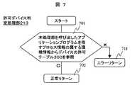
図7は、許可デバイス判定処理部213の処理フローを示す図である。許可デバイス判定処理部213では、ステップ701にて、本処理部213を呼び出したアプリケーションプログラムを指すプロセス情報が属する環境情報のデバイスアクセス許可テーブル300の指定されたデバイスを指すエントリを参照し、許可フラグ302の値を判断する。「○」であればステップ702に進む。ステップ702では、正常リターンする。「×」であればステップ711に進む。ステップ711ではエラーリターンする。
【0062】
図8は、ファイルシステム処理部214が有する処理部とデータ構造を示す図である。ファイルシステム処理部214には、open処理部801、close処理部802、read処理部803、write処理部804、seek処理部805、mkdir処理部806、rmdir処理部807、mount処理部808、umount処理部809およびremove処理部800と、ファイルシステムテーブル810を備える。
【0063】
open処理部801は、指定したファイルのアクセス権を得る処理を行う。close処理部802は、アクセス権を放棄する処理を行う。read処理部803は、open処理でアクセス権を獲得したファイルからデータを読み出す処理を行う。write処理部804は、open処理でアクセス権を獲得したファイルにデータを書き込む処理を行う。seek処理部805は、open処理でアクセス権を獲得したファイルに対して次に読み書きするファイル上の位置を変更する処理を行う。mkdir処理部806は、新規にディレクトリを作成する処理を行う。rmdir処理部807は、指定したディレクトリを削除する処理を行う。mount処理部808は、指定したディスク上にあるファイルシステムを名前空間上に接続する処理を行う。umount処理部809は、ファイルシステムのmountを解除する処理を行う。remove処理部800は、指定したファイルを削除する処理を行う。
【0064】
ファイルシステムテーブル810は、mountしているファイルシステムを示しており、811はファイルシステムIDのフィールド、812はデバイスIDのフィールド、813はハンドルのフィールドである。行821が示すエントリは、rootFSというIDをもつファイルシステムが第1ディスク151上に作られており、ストレージI/O処理部215を経由して第1ディスク151にアクセスするためのハンドルh1を保持していることを示している。行822が示すエントリは、FS1というIDをもつファイルシステムが第2ディスク152上に作られており、ストレージI/O処理部215を経由して第2ディスク152にアクセスするためのハンドルh2を保持していることを示している。行823が示すエントリは、FS2というIDをもつファイルシステムが第3ディスク153上に作られており、ストレージI/O処理部215を経由して第3ディスク153にアクセスするためのハンドルh3を保持していることを示している。
【0065】
図9は、ファイルシステム処理部214の処理部のうち、デバイス割り当てを伴うmount処理部808の処理フローを示す図である。mount処理部808では、ステップ901にて、許可デバイス判定処理部213を呼びmountに指定されたデバイスのアクセス権を検査する。ステップ902では、ステップ901のアクセス権の検査の結果、アクセスが許可されていた場合ステップ903に進み、許可されていなかった場合ステップ911に進む。ステップ911では、エラーリターンする。ステップ903では、ストレージI/O処理部215を呼びオープンする。すなわちデバイスにアクセスするためのハンドルを獲得する。ステップ904では、ファイルシステムテーブル810に、ステップ903で獲得したハンドルのエントリを追加する。ステップ905では、本処理部214を呼び出したアプリケーションプログラムを指すプロセス情報が属する環境情報のマウントテーブル331にエントリを追加する。ステップ906では、正常リターンする。
【0066】
図10は、ストレージI/O処理部215が有する処理部とデータ構造を示す図である。ストレージI/O処理部215には、open処理部1001、close処理部1002、read処理部1003、write処理部1004、ioctl処理部1005と、ハンドルリスト1010を備える。
【0067】
open処理部1001は、指定されたデバイスに対するアクセスが許可されているかを判定し、アクセス可能であれば以後の処理で使用するハンドルを与える。close処理部1002は、不要となったハンドルを無効化する。read処理部1003は、open処理部1001でハンドルを獲得した際に指定したデバイスからデータを読み込む。write処理部1004は、open処理部1001でハンドルを獲得した際に指定したデバイスにデータを書き込む。ioctl処理部1005は、open処理部1001でハンドルを獲得した際に指定したデバイスに対してデバイス固有の操作を行う。
【0068】
ハンドルリスト1010は、ストレージI/O処理部215が与えたハンドルのリストを示している。ハンドルリスト1010には、ハンドルのフィールド1011、デバイスIDのフィールド1012および実行中I/Oのフィールド1013を備える。行1021で示すエントリは、ハンドルh1が第1ディスク151に対するアクセスを行うために用いられることおよび実行中のI/Oが無い(「−」)ことを示している。行1022はハンドルh2が第2ディスク152に対するアクセスを行うために用いられることおよび実行中のI/Oが無い(「−」で表示)ことを、行1023はハンドルh3が第3ディスク153に対するアクセスを行うために用いられることおよび実行中のI/Oが無いことを、行1024はハンドルh4が第2ディスク152に対するアクセスを行うために用いられることおよび実行中のI/Oが無いことを、それぞれ、示している。行1025は、ハンドルh5がテープ装置154に対するアクセスを行うために用いられることおよび実行中I/Oがテープ装置154に対するI/Oであり、第2プロセス情報222が指すA社用管理プログラム202がI/O実行の完了を待っていることを示している。
【0069】
図11は、ストレージI/O処理部215のうち、デバイスのアクセス許可を判断するopen処理部1001の処理フローを示す図である。open処理部1001では、ステップ1101にて、許可デバイス判定処理部213を呼び、指定されたデバイスのアクセス権を検査する。ステップ1102では、ステップ1101のアクセス権の検査の結果、アクセスが許可されていた場合ステップ1103に進み、許可されていなかった場合ステップ1111に進む。ステップ1111では、エラーリターンする。ステップ1103では、指定されたデバイスに対する新たなハンドルを作成し、ハンドルリスト1010に新たなエントリを登録する。ステップ1104では、ハンドルを返し、正常リターンする。
【0070】
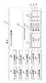
図12は、情報処理装置101上で稼働する装置管理プログラム201の処理フローを示す図である。装置管理プログラム201では、ステップ1201にてデータセンタ管理者用PC147からの要求を待つ。管理者用PC147から要求が到着すると、ステップ1202に進み、処理要求の内容を判断する。要求が「A社環境情報生成始動」であればステップ1211に進み、要求が「B社環境情報生成始動」であればステップ1212に進み、要求が「A社テープ有効化」であればステップ1231に進み、要求が「B社テープ有効化」であればステップ1241に進む。
【0071】
ステップ1211では、A社用ファイルサーバプログラム203の環境情報を生成するため、A社に提供する第2ディスク152とA社ネットワークI/F122へのアクセスを許可し、アクセス可能なディレクトリを分離するため、ルートディレクトリを「/env1」とする環境情報生成を指定し、A社用管理プログラム202を起動するようプロセス情報生成処理部211を呼ぶ。これにより、A社用ファイルサーバプログラム203を実行するA社環境情報232が生成され、A社環境情報232の下で稼働する最初のプロセス情報が指すアプリケーションプログラムが起動される。
【0072】
ステップ1221では、B社用ファイルサーバプログラム205の環境情報を生成するため、B社に提供する第3ディスク153とB社ネットワークI/F123へのアクセスを許可し、アクセス可能なディレクトリを分離するため、ルートディレクトリを「/env2」とする環境情報生成を指定し、B社用管理プログラム204を起動するようプロセス情報生成処理部211を呼ぶ。これにより、B社用ファイルサーバプログラム205を実行するB社環境情報233が生成され、B社環境情報233の下で稼働する最初のプロセス情報が指すアプリケーションプログラムが起動される。
【0073】
ステップ1231では、B社環境情報233から、テープ装置154の許可を取り消す様指定し環境情報変更処理部212を呼ぶ。ステップ1232では、A社環境情報232に、テープ装置154のアクセスを許可する様に指定し環境情報変更処理部212を呼ぶ。これにより、A社環境情報232の下で第3プロセス情報223からテープ装置154が利用可能となる。
【0074】
ステップ1241では、A社環境情報232から、テープ装置154の許可を取り消す様に指定し環境情報変更処理部212を呼ぶ。ステップ1242では、B社環境情報233に、テープ装置154のアクセスを許可する様指定し環境情報変更処理部212を呼ぶ。これにより、B社環境情報233の下で第5プロセス情報225からテープ装置154が利用可能となる。
【0075】
ここで、ステップ1231およびステップ1241によるA社環境情報232およびB社環境情報233に対するテープ装置154の許可は、それぞれに対する契約に基づいて、異なった時間帯になされるものであるのは当然である。
【0076】
これらのステップ1211、1221、1232および1242の処理が終わるとステップ1201に戻り、次の処理要求を待つ。
【0077】
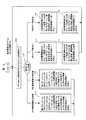
図13は、情報処理装置101上で稼働するA社用管理プログラム202の処理フローを示す図である。A社用管理プログラム202では、装置管理プログラム201のステップ1211でA社のサーバ環境情報生成を始動させるため、A社用管理プログラム202を起動するようプロセス情報生成処理部211が呼ばれたのに応じて起動され、ステップ1301にて、A社ネットワークI/F122のアドレス設定、および、ルーティングテーブルの設定を行う。ステップ1302にて、第2ディスクを「/exports/fs1」にマウントするようファイルシステム処理部214のmount処理部808を呼ぶ。ステップ1303にて、A社用ファイルサーバプログラム203を指定してプロセス情報生成処理部211を呼ぶ。これにより、A社用ファイルサーバプログラム203がA社環境情報232の下で実行を開始する。A社用ファイルサーバプログラム203は、「/exports/fs1」を公開し、A社Webサーバ148に対してファイル共有サービスを提供する。
【0078】
ステップ1304では、A社Webサーバ148からの要求を待つ。A社Webサーバ148からの要求が到着すると、ステップ1305に進み、要求に応じた処理を行う。要求が「ファイルサーバ停止」であればステップ1311に進み、要求が「ファイルサーバ再開」であればステップ1321に進み、要求が「バックアップ」であればステップ1331に進む。
【0079】
ステップ1311では、A社用ファイルサーバプログラム203を指す第3プロセス情報223を指定し、実行を停止するようプロセス情報制御処理部217を呼ぶ。これにより、A社用ファイルサーバプログラム203の活動は停止する。ステップ1321では、A社用ファイルサーバプログラム203を指す第3プロセス情報223を指定し、実行を再開するようプロセス情報制御処理部217を呼ぶ。これにより、停止していたA社用ファイルサーバプログラム203の活動は再開する。ステップ1331では、「/exports/fs1」以下のファイルをテープ装置154にバックアップするようバックアップコマンドを指定し、プロセス情報生成処理部211を呼ぶ。A社環境情報232の下で、バックアップコマンドが起動され、指定されたディレクトリ以下のファイルをテープ装置154に送りバックアップが行われる。
【0080】
ここで、ステップ1301からステップ1303の処理は、図12に示した装置管理プログラム201のプログラムのステップ1211で、新たな環境情報が生成されることになって、A社用管理プログラム202の起動のためのプロセス情報生成処理部が呼ばれるたびに実行されるものである。
【0081】
図13に示したA社用管理プログラム202の処理フローおよび上記A社用ファイルサーバプログラム203の処理は、B社用管理プログラム204およびB社用ファイルサーバプログラム205でも同様である。
【0082】
これまで記述した実施の形態1の環境情報の下で動作する仮想的なサーバ機能は、ここで示したファイルサーバ以外でも、NISサーバや、DNSサーバ、LDAPサーバ、Webサーバ、Proxyサーバ、さらに、これらサーバの組み合わせでも利用可能である。さらにステップ1305で行う要求に応じた処理を追加しても本発明に支障は無い。例えば、ファイルサーバの共有設定を変更する処理を追加することは容易である。
【0083】
また、実施の形態1では、第1ディスク151〜第3ディスク153を物理デバイスとして扱ったが、これを、たとえば、単一ディスクを複数に分割するパーティション機能を用い、各パーティションを論理的に別なディスク(論理ボリーム)として扱うことも可能である。また、RAID装置のように複数の物理デバイスを論理的に切り分け、論理デバイスとして仮想化した場合も同様に論理デバイスを別なディスクとして扱うことができる。さらに、この論理デバイスをパーティション分割する場合も同様である。このような処理に対応して、図3に例示したA社環境情報232のデバイスアクセス許可テーブル300のデバイスID301の表現法が変わることは当然である。
【0084】
(実施の形態2)
上述の実施の形態1では、図4に示したように、プロセス情報生成処理部211のインタフェースにおける生成する環境情報のルートディレクトリの情報として、ディレクトリを指定するよう記述しているが、これを、mountするファイルシステムが格納されているデバイス名を指定するものに置き換えることも可能である。
【0085】
図14は、プロセス情報生成処理において環境情報を生成する際、ルートファイルシステムをmountする機能を持つプロセス情報生成処理部211’としたときの処理フローを示す図である。図4に示したステップと同じ機能を持つステップには同じ参照符号を付した。
【0086】
ステップ401にて、本処理部211’を呼び出したアプリケーションプログラムが環境情報生成要求を伴うか否かを判定する。環境情報生成要求を伴う呼び出しの場合ステップ402に進み、環境情報生成要求を伴わない呼び出しの場合ステップ411に進む。ステップ411では、本処理部211’を呼び出したアプリケーションプログラムを指すプロセス情報の属する環境情報を指すポインタを変数pに代入し、ステップ404に進む。ステップ402では、本処理部211’を呼び出したアプリケーションプログラムを指すプロセス情報が管理環境情報231に属しているか否かを判定する。管理環境情報231に属している場合ステップ403に進み、管理環境情報231に属していない場合ステップ421に進む。ステップ421ではエラーリターンする。ステップ403では、新たに環境情報を生成し、指定されたデバイスへのアクセス許可、ネットワークI/Fおよびルートディレクトリの情報を、管理環境情報231に反映するとともに、変数pに生成した環境情報へのポインタを代入し、ステップ1431に進む。ステップ1431では、ストレージI/O処理部215を呼び、ハンドルを獲得する。ステップ1432では、ファイルシステムテーブル810にエントリを追加する。ステップ1433では、ステップ1403で生成した環境情報のマウントテーブル331にエントリを追加する。次に、ステップ404に進む。ステップ404では、プロセス情報を生成する。ステップ405では、生成したプロセス情報を変数pが指す環境情報のプロセス情報リスト360に登録する。ステップ406では、正常リターンする。
【0087】
プロセス情報生成処理部211’は、たとえば以下に示すインタフェースを提供する。
[関数]create_process_with_mount(cmd、rdev、netif、dev)、
[引数]cmd:起動するコマンド、
rdev:生成する環境情報のルートディレクトリにmountするファイルシステムを格納したデバイスを指定、
netif:環境情報に登録するネットワークインタフェースのリスト、
dev:アクセスを許可するデバイスのリスト、
[説明]rdev、netif、devをなしに呼び出すと、呼び出しプロセス情報と同じ環境情報にcmdに指定したプロセス情報が指すアプリケーションプログラムを起動する。rdev、netif、devいずれかを指定するとrdev、netif、devで指定した環境情報を生成し、生成した環境情報でcmdに指定したプロセス情報が指すアプリケーションプログラムを起動する。
【0088】
また、ユーザは、次に示すインタフェースを持つコマンドを用いてプロセス情報生成処理部211’を呼び出すことができる。
[コマンド書式]newenv_mount コマンド名 ルートデバイス名 ネットワークインタフェース名 デバイス名
[引数]コマンド名:起動するコマンド、
ルートデバイス名:生成する環境情報のルートディレクトリにmountするファイルシステムを格納したデバイス名を指定、
ネットワークインタフェース名:環境情報に登録するネットワークインタフェース名、複数指定できる、
デバイス名:アクセスを許可するデバイス名、複数指定できる、
[説明]ルートデバイス名、ネットワークインタフェース名、デバイス名で指定した環境情報を生成し、その環境情報で稼働するコマンド名で指定したプロセス情報が指すアプリケーションプログラムを起動する。
【0089】
なお、許可するデバイスの変わりに、アクセスを禁止するデバイスを引数とするインタフェースを提供することもできる。
【0090】
プロセス情報生成処理部211’によりルートディレクトリをmountし、生成された環境情報は、ルートディレクトリも管理環境情報231を含む他の環境情報から独立することができる。
【0091】
【発明の効果】
本発明では、環境情報で制限されたプロセス情報は、管理者権限であってもそのプロセス情報が指すアプリケーションプログラムが稼働する環境情報に指定された範囲を越えて他のデバイスや、ファイルシステムをアクセスすることができないため、環境情報毎に管理者権限を与えることができる。環境情報毎の管理者は、与えられた範囲で、ファイルシステムのマウント/アンマウントや、バックアップ、ネットワークファイルシステムの共有設定の変更などを自由に行うことが可能となる。
【図面の簡単な説明】
【図1】本発明を適用して効果のあるシステムの一例を示す図。
【図2】情報処理装置101上で稼働する主要なソフトウェアおよびデータおよびこれらの関連を示す図。
【図3】環境情報の具体例の詳細をA社環境情報232を例に用いて示す図。
【図4】プロセス情報生成処理部211の処理フローを示す図。
【図5】プロセス情報制御処理部217の処理フローを示す図。
【図6】環境情報変更処理部212の処理フローを示す図。
【図7】許可デバイス判定処理部213の処理フローを示す図。
【図8】ファイルシステム処理部214が有する処理機能とデータ構造を示す図。
【図9】ファイルシステム処理部214の処理機能のうち、デバイス割り当てを伴うmount処理部808の処理フローを示す図。
【図10】ストレージI/O処理部215が有する処理機能とデータ構造を示す図。
【図11】ストレージI/O処理部215のうち、デバイスのアクセス許可を判断するopen処理部1001の処理フローを示す図。
【図12】情報処理装置101上で稼働する装置管理プログラム201の処理フローを示す図。
【図13】情報処理装置101上で稼働するA社用管理プログラム202の処理フローを示す図。
【図14】プロセス情報生成処理において環境情報生成する際、ルートファイルシステムをmountする機能を持つプロセス情報生成処理部211’としたときの処理フローを示す図。
【符号の説明】
100…データセンタ、101…情報処理装置、113…バス、111…CPU、112…メモリ、121…管理ネットワークI/F、122…A社ネットワークI/F、123…B社ネットワークI/F、131…ストレージI/F、141…管理LAN、142…A社LAN、143…B社LAN、144…ファイアウオールA、145…ファイアウオールB、146…インターネット、147…データセンタ管理者用PC、148…顧客A社のWebサーバ、149…顧客B社のWebサーバ、151…第1ハードディスク、152…第2ハードディスク、153…第3ハードディスク、154…テープ装置、161,162…A社,B社管理者用PC、163−165…一般ユーザ、201…装置管理プログラム、202…A社用管理プログラム、203…A社用ファイルサーバプログラム、204…B社用管理プログラム、205…B社用ファイルサーバプログラム、210…OS(オペレーティングシステム)、211…プロセス情報生成処理部、212…環境情報変更処理部、213…許可デバイス判定処理部、214…ファイルシステム処理部、215…ストレージI/O処理部、216…管理ネットワークI/F処理部、217…プロセス情報制御処理部、221…第1プロセス情報、222…第2プロセス情報、223…第3プロセス情報、224…第4プロセス情報、225…第5プロセス情報、231…管理環境情報、232…A社環境情報、233…B社環境情報、241…管理ネットワークI/F情報、242…A社ネットワークI/F情報、243…B社ネットワークI/F情報、300…デバイスアクセス許可テーブル、301…デバイスIDを格納するフィールド、302…許可フラグを格納するフィールド、311−314…行、320…ネットワークI/Fリスト、330…ファイルシステム設定情報、331…マウントテーブル、332…マウントポイントを格納するフィールド、333…ファイルシステムIDを格納するフィールド、334…inode番号を格納するフィールド、335…元のファイルシステムIDを格納するフィールド、336…元のinode番号を格納するフィールド、340…ネットワーク設定情報、341…ルーティングテーブル、342…プロトコルテーブル、343…プロトコル、344…ソケットリスト、345…行き先を格納するフィールド、346…どこへ送れば良いかを示す情報を格納するフィールド、347…どのインタフェースを用いるかを示す情報を格納するフィールド、351,352…行、360…プロセス情報リスト、361,362…行、371,372…行、381,382,391,392…ソケット、800…remove処理部、801…open処理部、802…close処理部、803…read処理部、804…write処理部、805…seek処理部、806…mkdir処理部、807…rmdir処理部、808…mount処理部、809…umount処理部、810…ファイルシステムテーブル、811…ファイルシステムIDのフィールド、812…デバイスIDのフィールド、813…ハンドルのフィールド、821−823…行、1001…open処理部、1002…close処理部、1003…read処理部、1004…write処理部、1005…ioctl処理部、1010…ハンドルリスト、1011…ハンドルのフィールド、1012…デバイスIDのフィールド、1013…実行中I/Oのフィールド、1021−1025…行。[0001]
TECHNICAL FIELD OF THE INVENTION
The present invention relates to a network-attached storage, a server system, and an operating system.
[0002]
[Prior art]
When a company provides a service using the Internet, a service provided by a data center may be used in order to reduce costs for constructing Internet connection facilities and computer systems.
[0003]
Data center companies have Internet connection facilities and lend out server installation spaces and server devices of companies (customers) who want to provide services using the Internet. Normally, storage lent to customers is often allocated to individual devices in order to maintain security between customers.
[0004]
However, in the method of allocating devices to each customer, it is difficult to flexibly change the capacity of the lent storage according to changes in customer demand, and it is necessary to monitor all devices in case of device failure There is a problem that the management cost increases due to an increase in the number of devices.
[0005]
By logically dividing the large-capacity storage device and connecting the server device of the customer and the large-capacity storage device as a logical volume by SAN (Storage Area Network), the storage management can be centralized and the management cost can be reduced. It is possible to reduce. However, fiber channel (Fiber Channel) interfaces, which are currently the mainstream in SANs, are expensive, and customers have contracted for an amount corresponding to the installation space. There is a problem such as no space left.
[0006]
A NAS (Network Attached Storage) device uses an NFS service or a CIFS service, and is built into the NAS device or a file system created on a storage connected via a storage interface such as SCSI or Fiber Channel. It is possible to store a file in another information processing apparatus and to share the file through another. The NAS device can publish the file system under the designated directory, and can set to publish a plurality of directories.
[0007]
In data centers, almost all customer servers are provided with a network interface because the purpose is to connect to the Internet. The NAS device can provide a storage service to a plurality of customers without adding hardware to the customer server. However, the NAS device often uses a general-purpose OS (operating system), and may be damaged by hacking by a malicious user, falsification of a file by a virus or the like, deletion of a file, and the like. When a plurality of customers share a NAS device, these damages may affect all customers sharing the same NAS device.
[0008]
MultiStore (Non Patent Literature 1) is a NAS device manufactured by Network Appliance. According to this, a virtual server such as a CIFS service or an NFS service having one or more IP addresses and volumes called a plurality of vfilers can be provided on one device. By assigning a vfiler to each customer, user management for each customer and individual settings can be performed.
[0009]
The vfiler allows a customer to execute a command using the rsh protocol and can change the setting of the NFS service, but cannot use a backup device connected to the NAS device. In order to use a backup device connected to the NAS device, it is necessary to use a device that manages the entire device.
[0010]
Patent Document 1 discloses a system that provides a service by assigning an independent OS to each customer by using a virtual machine. In the technique described in Patent Document 1, a plurality of OSs operate on one computer, and independent resources such as a main memory and a network adapter are assigned to each OS. Since resources are not shared between OSs, user management for each customer, individual settings, and the like can be easily performed. Furthermore, by allocating the resources of the backup device, it can be used for backup and the like.
[0011]
[Patent Document 1]
JP 2002-024192 A
[Non-patent document 1]
“Data ONTAP 6.2 MultiStore Administration Guide”, Network Appliance (Inc.), [Search November 28, 2002], Internet, <URL : Http: //news.netapp.com/nowsforms/login.fcc> and input the user name and password. <URL: http: //now.netapp.com/NOW/knowledge/docs/ontap/ rel62 / pdfs / vfiler.pdf>.
[0012]
[Problems to be solved by the invention]
As described above, it becomes possible for a data center company to secure security for a company (customer) who wants to provide a service using the Internet and to change the capacity of a storage to be lent according to a change in demand. However, there are advantages and disadvantages only in selecting the conventional system. For example, in a method in which a plurality of customers share a NAS device using a general-purpose OS, if a NAS device is hacked due to a security hole of one customer, resources for each customer are not isolated on the NAS device. All customers who share the device may be harmed. When using a backup device connected to the NAS device with the NAS device and making a backup, the application such as a database using the file sharing service of the NAS device is placed in the backup mode, and the data on the disk is kept in a consistent state. It is necessary to link the operation of the customer server to be performed with the backup operation of transferring data to the backup device, and the operation is complicated.
[0013]
In the MultiStore method, since the management authority of the tape device or the like does not exist on the customer side, the backup cannot be obtained only by the operation on the customer side. With vfiler, the range of management authority given to customers cannot be flexibly changed. When the management authority is given to a customer, for example, when restoring data from a tape device, it is conceivable that an operation error on the customer side causes the data to be expanded to the disk area of another customer, causing damage to the other customer. . In addition, security problems between customers such as peeping data of other customers occur.
[0014]
Further, in the method using virtual machines, all resources are allocated to each virtual machine, but imbalance in resource allocation may occur depending on the operation status of the virtual machines. For example, the cache area for caching data on the disk in the main memory and accelerating file access is independent for each virtual machine. It cannot be allocated to a high virtual machine cache area. This is because it is not easy to change the assignment of the main memory, and it is necessary to restart the virtual machine, for example.
[0015]
[Means for Solving the Problems]
According to the present invention, it is possible to realize a data center functioning as a virtual server which can individually permit or restrict not only the IP address and the volume but also the access right of the physical / logical device, and further increase the degree of freedom of operation management. By limiting the physical devices or logical devices that can be accessed from the virtual server, it is possible to eliminate the effects of unauthorized access from customers and to flexibly give customers the management authority required for operation management.
[0016]
Specifically, a function for finely setting the management right given to the customer side to the OS and a function for restricting the operation of the customer from exceeding the range of the management right given to the customer side are incorporated. Specifically, environment information for executing the application program indicated by the process information is added to the process information managed by the OS, and the environment information is also inherited by newly generated process information. Thereby, the environment information is added to all the process information of the application program executed by the customer. The environment information includes an accessible physical device or logical device, an accessible network I / F (interface), a network routing table, a protocol table, a file system mount table, and a process information list belonging to the environment information. .
[0017]
The data center manager is provided with a function of generating process information having designated environment information and a function of changing environment information.
[0018]
Furthermore, in order to solve the problem that a backup cannot be made on a tape only by the operation of the customer, the management authority of the tape device must be given to the customer in advance as one of the environmental information on the OS, and The data center manager uses the function of changing the environment information, and gives the customer the management authority of the tape device when necessary.
[0019]
According to the present invention, since a virtual server function for each customer is realized on a single OS that collectively manages shared resources, the resources collectively managed by the OS correspond to requests from any application program indicated by the process information. Are used equally, so that resources can be effectively used according to the load, and the problem of load imbalance in the virtual machine does not occur.
[0020]
BEST MODE FOR CARRYING OUT THE INVENTION
(Embodiment 1)
Hereinafter, Embodiment 1 of the present invention will be described in detail with reference to FIGS. First, an outline of components related to the present invention will be described, and then details of a processing procedure and a data structure will be described.
[0021]
FIG. 1 is a diagram showing an example of a system that is effective by applying the present invention. 100 is a data center. An
[0022]
The
[0023]
The storage I /
[0024]
The
[0025]
Therefore, it is important that the
[0026]
FIG. 2 is a diagram illustrating main programs and information that operate on the
[0027]
In the memory 112 of the
[0028]
The
[0029]
The
[0030]
The
[0031]
The operations of the company
[0032]
The
[0033]
The information to be stored includes
[0034]
The
[0035]
The
[0036]
The
[0037]
The
[0038]
Although the
[0039]
Although the company A
[0040]
Although the company
[0041]
The management network I /
[0042]
The process information
[0043]
The process information
[0044]
The environment information
[0045]
When an application program requests access to a device, the permitted device
[0046]
The file
[0047]
The storage I /
[0048]
The network I /
[0049]
FIG. 3 is a diagram illustrating details of a specific example of the environment information using the company A
[0050]
The device access permission table 300 shows a correspondence between a field 301 for storing a device ID and a
[0051]
In the network I / F list 320, company A network I /
[0052]
The file
[0053]
The
[0054]
In the
[0055]
FIG. 4 is a diagram illustrating a processing flow of the process information
[0056]
The process information
[Function] create_process (cmd, dir, netif, dev),
[Argument] cmd: Command to start,
dir: Specifies the root directory of environment information to be generated,
netif: list of network interfaces to be registered in environment information,
dev: list of devices to which access is allowed,
[Explanation] When dir, netif, and dev are called without the same, the application program indicated by the process information specified in the cmd is started in the same environment information as the calling process information. When one of dir, netif, and dev is specified, the environment information specified by dir, netif, and dev is generated, and the application program indicated by the process information specified by cmd is started by the generated environment information.
[0057]
The user can call the process information
[Command format] newenv command name root directory network interface name device name
[Argument] command name: command to start,
Root directory: Specify the root directory of the environment information to be generated,
Network interface name: Network interface name to be registered in environment information, multiple can be specified.
Device name: The name of the device for which access is permitted
[Description] Generates environment information specified by a root directory, a network interface name, and a device name, and starts an application program indicated by process information specified by a command name operated by the environment information.
[0058]
It is also possible to provide an interface that uses a device for which access is prohibited as an argument instead of a device for which access is permitted.
[0059]
FIG. 5 is a diagram illustrating a processing flow of the process information
[0060]
FIG. 6 is a diagram illustrating a processing flow of the environment information
[0061]
FIG. 7 is a diagram illustrating a processing flow of the permitted device
[0062]
FIG. 8 is a diagram illustrating a processing unit and a data structure of the file
[0063]
The
[0064]
The file system table 810 indicates a mounted file system.
[0065]
FIG. 9 is a diagram showing a processing flow of the
[0066]
FIG. 10 is a diagram illustrating a processing unit and a data structure of the storage I /
[0067]
The open processing unit 1001 determines whether access to the specified device is permitted, and if accessible, gives a handle to be used in subsequent processing. The
[0068]
The
[0069]
FIG. 11 is a diagram showing a processing flow of the open processing unit 1001 of the storage I /
[0070]
FIG. 12 is a diagram showing a processing flow of the
[0071]
In
[0072]
In
[0073]
In
[0074]
In
[0075]
Here, the permission of the
[0076]
When these
[0077]
FIG. 13 is a diagram illustrating a processing flow of the
[0078]
In
[0079]
In
[0080]
Here, in the processing from
[0081]
The processing flow of the
[0082]
The virtual server function that operates under the environment information of the first embodiment described so far is a NIS server, a DNS server, an LDAP server, a Web server, a Proxy server, and a file server other than the file server shown here. A combination of these servers is also available. Furthermore, there is no problem in the present invention even if a process corresponding to the request performed in
[0083]
Further, in the first embodiment, the
[0084]
(Embodiment 2)
In the above-described first embodiment, as shown in FIG. 4, a directory is specified as information of a root directory of environment information to be generated in the interface of the process information
[0085]
FIG. 14 is a diagram illustrating a processing flow when the process information
[0086]
In
[0087]
The process information generation processing unit 211 'provides, for example, the following interface.
[Function] create_process_with_mount (cmd, rdev, netif, dev),
[Argument] cmd: Command to start,
rdev: Designates a device that stores a file system to be mounted in the root directory of environment information to be generated,
netif: list of network interfaces to be registered in environment information,
dev: list of devices to which access is allowed,
[Explanation] When rdev, netif, and dev are called without any, the application program indicated by the process information designated by cmd in the same environment information as the calling process information is started. When any of rdev, netif, and dev is specified, environment information specified by rdev, netif, and dev is generated, and the application program indicated by the process information specified by cmd is started by the generated environment information.
[0088]
Further, the user can call the process information
[Command format] newenv_mount Command name Root device name Network interface name Device name
[Argument] command name: command to start,
Root device name: Specify the device name that stores the file system to be mounted in the root directory of the environment information to be generated,
Network interface name: Network interface name to be registered in environment information, multiple can be specified.
Device name: The name of the device for which access is permitted
[Description] Generates environment information specified by a root device name, a network interface name, and a device name, and starts an application program indicated by process information specified by a command name operated by the environment information.
[0089]
It should be noted that an interface using a device whose access is prohibited as an argument can be provided instead of a device that permits access.
[0090]
The root directory is mounted by the process information
[0091]
【The invention's effect】
In the present invention, the process information restricted by the environment information can access other devices and file systems beyond the range specified in the environment information in which the application program indicated by the process information runs even with the administrator authority. Since it is not possible to do so, administrator authority can be given for each piece of environmental information. The administrator for each environment information can freely mount / unmount the file system, perform backup, change the sharing setting of the network file system, and the like within a given range.
[Brief description of the drawings]
FIG. 1 is a diagram showing an example of a system that is effective by applying the present invention.
FIG. 2 is a diagram showing main software and data operating on the
FIG. 3 is a diagram showing details of a specific example of environment information using company A
FIG. 4 is a diagram showing a processing flow of a process information
FIG. 5 is a diagram showing a processing flow of a process information
FIG. 6 is a diagram showing a processing flow of an environment information
FIG. 7 is a diagram showing a processing flow of a permitted device
FIG. 8 is a view showing a processing function and a data structure of a file
FIG. 9 is a diagram showing a processing flow of a
FIG. 10 is a diagram showing a processing function and a data structure of a storage I /
FIG. 11 is a diagram showing a processing flow of an open processing unit 1001 of the storage I /
FIG. 12 is a diagram showing a processing flow of a
FIG. 13 is a diagram showing a processing flow of a
FIG. 14 is a diagram showing a processing flow when a process information
[Explanation of symbols]
100 data center, 101 information processing device, 113 bus, 111 CPU, 112 memory, 121 management network I / F, 122 company A network I / F, 123 company B network I / F, 131 ... Storage I / F, 141 ... Management LAN, 142 ... Company A LAN, 143 ... Company B LAN, 144 ... Firewall A, 145 ... Firewall B, 146 ... Internet, 147 ... PC for data center manager, 148 ... Customer A 149: Web server of customer B, 151: first hard disk, 152: second hard disk, 153: third hard disk, 154: tape device, 161, 162: PC for company A and company B administrator 163-165: General user 201: Device management program 202: Company A pipe Program 203: Company A file server program, 204: Company B management program, 205: Company B file server program, 210: OS (operating system), 211: Process information generation processing unit, 212: Environment information change processing Unit, 213: permitted device determination processing unit, 214: file system processing unit, 215 ... storage I / O processing unit, 216 ... management network I / F processing unit, 217 ... process information control processing unit, 221 ... first process information , 222 ... second process information, 223 ... third process information, 224 ... fourth process information, 225 ... fifth process information, 231 ... management environment information, 232 ... company A environment information, 233 ... company B environment information, 241 ... Management network I / F information, 242 ... Company A network I / F information, 243 Company B network I / F information, 300: Device access permission table, 301: Field for storing device ID, 302: Field for storing permission flag, 311-314: Line, 320: Network I / F list, 330: File System setting information, 331: mount table, 332: field for storing mount point, 333 ... field for storing file system ID, 334 ... field for storing inode number, 335 ... field for storing original file system ID, 336 ... field storing original inode number, 340 ... network setting information, 341 ... routing table, 342 ... protocol table, 343 ... protocol, 344 ... socket list, 345 ... field storing destination Field, 346... Field for storing information indicating where to send, 347... Field for storing information indicating which interface to use, 351, 352... Line, 360... Process information list, 361, 362. , 371, 372 ... line, 381, 382, 391, 392 ... socket, 800 ... remove processing unit, 801 ... open processing unit, 802 ... close processing unit, 803 ... read processing unit, 804 ... write processing unit, 805 ... seek 806: mkdir processing unit, 807: rmdir processing unit, 808: mount processing unit, 809: umount processing unit, 810: file system table, 811: file system ID field, 812: device ID field, 813 ... Handle field, 821 823 line, 1001 open processing unit, 1002 close processing unit, 1003 read processing unit, 1004 write processing unit, 1005 ioctl processing unit, 1010 handle list, 1011 handle field, 1012 device ID Field, 1013... Field of I / O being executed, 1021-1025.
Claims (14)
Translated fromJapanesePriority Applications (3)
| Application Number | Priority Date | Filing Date | Title |
|---|---|---|---|
| JP2003011965AJP4567293B2 (en) | 2003-01-21 | 2003-01-21 | file server |
| US10/375,197US7673012B2 (en) | 2003-01-21 | 2003-02-28 | Virtual file servers with storage device |
| US12/687,305US7970917B2 (en) | 2003-01-21 | 2010-01-14 | Virtual file servers with storage device |
Applications Claiming Priority (1)
| Application Number | Priority Date | Filing Date | Title |
|---|---|---|---|
| JP2003011965AJP4567293B2 (en) | 2003-01-21 | 2003-01-21 | file server |
Publications (2)
| Publication Number | Publication Date |
|---|---|
| JP2004227127Atrue JP2004227127A (en) | 2004-08-12 |
| JP4567293B2 JP4567293B2 (en) | 2010-10-20 |
Family
ID=32709226
Family Applications (1)
| Application Number | Title | Priority Date | Filing Date |
|---|---|---|---|
| JP2003011965AExpired - Fee RelatedJP4567293B2 (en) | 2003-01-21 | 2003-01-21 | file server |
Country Status (2)
| Country | Link |
|---|---|
| US (2) | US7673012B2 (en) |
| JP (1) | JP4567293B2 (en) |
Cited By (13)
| Publication number | Priority date | Publication date | Assignee | Title |
|---|---|---|---|---|
| JP2006185218A (en)* | 2004-12-28 | 2006-07-13 | Fujitsu Ltd | Connection device restriction program and connection device restriction device |
| JP2006251936A (en)* | 2005-03-09 | 2006-09-21 | Hitachi Ltd | Computer system and data backup method in computer system |
| EP1710675A1 (en) | 2005-04-04 | 2006-10-11 | Hitachi, Ltd. | Storage controller and storage system |
| JP2007141231A (en)* | 2005-11-21 | 2007-06-07 | Internatl Business Mach Corp <Ibm> | Method, system and computer program for data backup |
| JP2008027279A (en)* | 2006-07-24 | 2008-02-07 | Hitachi Ltd | Method and system for controlling access to tape medium from a plurality of virtual machines |
| JP2008210045A (en)* | 2007-02-23 | 2008-09-11 | Hitachi Ltd | Storage system, information processing apparatus, and connection method |
| EP2120151A1 (en) | 2008-05-14 | 2009-11-18 | Hitachi, Ltd. | Storage system and method of managing a storage system using a management apparatus |
| JP2010507876A (en)* | 2006-10-26 | 2010-03-11 | アリババ グループ ホールディング リミテッド | Network data storage system and data access method thereof |
| JP2010079468A (en)* | 2008-09-25 | 2010-04-08 | Hitachi Ltd | File server resource division method, system, apparatus and program |
| US8015559B2 (en) | 2006-11-15 | 2011-09-06 | Hitachi, Ltd. | System software update method |
| WO2012160814A1 (en)* | 2011-05-24 | 2012-11-29 | 日本電気株式会社 | Information processing system, access rights management method, information processing device, and control method and control program therefor |
| US8880694B2 (en) | 2008-03-26 | 2014-11-04 | Hitachi, Ltd. | Server system and control method for same |
| US9377965B2 (en) | 2013-05-15 | 2016-06-28 | Fujitsu Limited | Storage control device for controlling physical storage device in storage system including virtual storage device, storage system including physical storage device and virtual storage device, and computer-readable recording medium storing control program for physical storage device in storage system including virtual storage device |
Families Citing this family (31)
| Publication number | Priority date | Publication date | Assignee | Title |
|---|---|---|---|---|
| US7814131B1 (en)* | 2004-02-02 | 2010-10-12 | Network Appliance, Inc. | Aliasing of exported paths in a storage system |
| US7630994B1 (en) | 2004-03-12 | 2009-12-08 | Netapp, Inc. | On the fly summarization of file walk data |
| US7844646B1 (en)* | 2004-03-12 | 2010-11-30 | Netapp, Inc. | Method and apparatus for representing file system metadata within a database for efficient queries |
| US7293039B1 (en) | 2004-03-12 | 2007-11-06 | Network Appliance, Inc. | Storage resource management across multiple paths |
| US7539702B2 (en)* | 2004-03-12 | 2009-05-26 | Netapp, Inc. | Pre-summarization and analysis of results generated by an agent |
| JP4448719B2 (en)* | 2004-03-19 | 2010-04-14 | 株式会社日立製作所 | Storage system |
| JP4473766B2 (en)* | 2005-04-04 | 2010-06-02 | 株式会社日立製作所 | Computer system, log collection method, and computer program |
| JP5046725B2 (en)* | 2007-04-24 | 2012-10-10 | 株式会社日立製作所 | Volume allocation management device |
| US8374929B1 (en) | 2007-08-06 | 2013-02-12 | Gogrid, LLC | System and method for billing for hosted services |
| EP2597816B1 (en) | 2007-09-26 | 2019-09-11 | Nicira Inc. | Network operating system for managing and securing networks |
| US8347359B2 (en) | 2007-12-28 | 2013-01-01 | Bruce Backa | Encryption sentinel system and method |
| JP5222573B2 (en)* | 2008-01-29 | 2013-06-26 | 株式会社日立製作所 | Server computer and network processing method |
| US8418174B2 (en)* | 2008-02-14 | 2013-04-09 | International Business Machines Corporation | Enhancing the scalability of network caching capability in virtualized environment |
| US7966517B2 (en)* | 2008-03-20 | 2011-06-21 | Hitachi, Ltd. | Method and apparatus for virtual network attached storage remote migration |
| JP2009237826A (en)* | 2008-03-26 | 2009-10-15 | Hitachi Ltd | Storage system and volume management method therefor |
| US8219653B1 (en) | 2008-09-23 | 2012-07-10 | Gogrid, LLC | System and method for adapting a system configuration of a first computer system for hosting on a second computer system |
| CN102726007B (en) | 2009-04-01 | 2015-04-08 | Nicira股份有限公司 | Method and apparatus for implementing and managing virtual switches |
| JP5360978B2 (en)* | 2009-05-22 | 2013-12-04 | 株式会社日立製作所 | File server and file operation notification method in file server |
| US8601226B1 (en) | 2010-05-20 | 2013-12-03 | Gogrid, LLC | System and method for storing server images in a hosting system |
| US8837493B2 (en) | 2010-07-06 | 2014-09-16 | Nicira, Inc. | Distributed network control apparatus and method |
| US10103939B2 (en) | 2010-07-06 | 2018-10-16 | Nicira, Inc. | Network control apparatus and method for populating logical datapath sets |
| US9680750B2 (en) | 2010-07-06 | 2017-06-13 | Nicira, Inc. | Use of tunnels to hide network addresses |
| US8964528B2 (en) | 2010-07-06 | 2015-02-24 | Nicira, Inc. | Method and apparatus for robust packet distribution among hierarchical managed switching elements |
| US9525647B2 (en) | 2010-07-06 | 2016-12-20 | Nicira, Inc. | Network control apparatus and method for creating and modifying logical switching elements |
| US9288117B1 (en) | 2011-02-08 | 2016-03-15 | Gogrid, LLC | System and method for managing virtual and dedicated servers |
| US8825900B1 (en) | 2011-04-05 | 2014-09-02 | Nicira, Inc. | Method and apparatus for stateless transport layer tunneling |
| US9043452B2 (en) | 2011-05-04 | 2015-05-26 | Nicira, Inc. | Network control apparatus and method for port isolation |
| US9002803B2 (en)* | 2011-06-07 | 2015-04-07 | Workday, Inc. | Role-based security policy for an object-oriented database system |
| US8880657B1 (en) | 2011-06-28 | 2014-11-04 | Gogrid, LLC | System and method for configuring and managing virtual grids |
| US9367560B1 (en)* | 2011-12-14 | 2016-06-14 | Unboundid, Corp. | Method, system and apparatus for synchronizing changes in a directory service |
| US10776384B1 (en) | 2013-04-30 | 2020-09-15 | Ping Identity Corporation | Method, server and system for criteria-based assured replication |
Citations (3)
| Publication number | Priority date | Publication date | Assignee | Title |
|---|---|---|---|---|
| JP2001325207A (en)* | 2000-05-17 | 2001-11-22 | Hitachi Ltd | Switch with built-in cache, computer system, and switch control method for switch with built-in cache |
| JP2001337863A (en)* | 2000-05-24 | 2001-12-07 | Hitachi Ltd | Storage control device, storage system, and security setting method for storage system |
| WO2002003220A2 (en)* | 2000-07-05 | 2002-01-10 | Ernst & Young Llp | Method and apparatus for providing computer services |
Family Cites Families (58)
| Publication number | Priority date | Publication date | Assignee | Title |
|---|---|---|---|---|
| US5761655A (en) | 1990-06-06 | 1998-06-02 | Alphatronix, Inc. | Image file storage and retrieval system |
| JP2868141B2 (en) | 1992-03-16 | 1999-03-10 | 株式会社日立製作所 | Disk array device |
| US6424715B1 (en) | 1994-10-27 | 2002-07-23 | Mitsubishi Corporation | Digital content management system and apparatus |
| US5901312A (en) | 1994-12-13 | 1999-05-04 | Microsoft Corporation | Providing application programs with unmediated access to a contested hardware resource |
| US5765200A (en) | 1995-06-07 | 1998-06-09 | International Business Machines Corporation | Logical positioning within a storage device by a storage controller |
| US5657445A (en) | 1996-01-26 | 1997-08-12 | Dell Usa, L.P. | Apparatus and method for limiting access to mass storage devices in a computer system |
| JP2982702B2 (en) | 1996-08-30 | 1999-11-29 | 日本電気株式会社 | Disk unit |
| US6393569B1 (en) | 1996-12-18 | 2002-05-21 | Alexander S. Orenshteyn | Secured system for accessing application services from a remote station |
| US6408336B1 (en) | 1997-03-10 | 2002-06-18 | David S. Schneider | Distributed administration of access to information |
| JP3228182B2 (en) | 1997-05-29 | 2001-11-12 | 株式会社日立製作所 | Storage system and method for accessing storage system |
| US5941972A (en) | 1997-12-31 | 1999-08-24 | Crossroads Systems, Inc. | Storage router and method for providing virtual local storage |
| US6101607A (en) | 1998-04-24 | 2000-08-08 | International Business Machines Corporation | Limit access to program function |
| US6336187B1 (en) | 1998-06-12 | 2002-01-01 | International Business Machines Corp. | Storage system with data-dependent security |
| US6421711B1 (en) | 1998-06-29 | 2002-07-16 | Emc Corporation | Virtual ports for data transferring of a data storage system |
| US6356863B1 (en)* | 1998-09-08 | 2002-03-12 | Metaphorics Llc | Virtual network file server |
| US6571245B2 (en)* | 1998-12-07 | 2003-05-27 | Magically, Inc. | Virtual desktop in a computer network |
| JP4252139B2 (en) | 1998-12-16 | 2009-04-08 | 株式会社日立製作所 | Storage system |
| US6643690B2 (en)* | 1998-12-29 | 2003-11-04 | Citrix Systems, Inc. | Apparatus and method for determining a program neighborhood for a client node in a client-server network |
| US7010554B2 (en) | 2002-04-04 | 2006-03-07 | Emc Corporation | Delegation of metadata management in a storage system by leasing of free file system blocks and i-nodes from a file system owner |
| US6324581B1 (en) | 1999-03-03 | 2001-11-27 | Emc Corporation | File server system using file system storage, data movers, and an exchange of meta data among data movers for file locking and direct access to shared file systems |
| JP3837953B2 (en) | 1999-03-12 | 2006-10-25 | 株式会社日立製作所 | Computer system |
| US6631442B1 (en)* | 1999-06-29 | 2003-10-07 | Emc Corp | Methods and apparatus for interfacing to a data storage system |
| US6714968B1 (en) | 2000-02-09 | 2004-03-30 | Mitch Prust | Method and system for seamless access to a remote storage server utilizing multiple access interfaces executing on the remote server |
| US20020103889A1 (en) | 2000-02-11 | 2002-08-01 | Thomas Markson | Virtual storage layer approach for dynamically associating computer storage with processing hosts |
| US7093005B2 (en) | 2000-02-11 | 2006-08-15 | Terraspring, Inc. | Graphical editor for defining and creating a computer system |
| US20020129048A1 (en) | 2000-03-03 | 2002-09-12 | Surgient Networks, Inc. | Systems and methods for resource monitoring in information storage environments |
| US20010039497A1 (en) | 2000-03-30 | 2001-11-08 | Hubbard Edward A. | System and method for monitizing network connected user bases utilizing distributed processing systems |
| US20010037379A1 (en) | 2000-03-31 | 2001-11-01 | Noam Livnat | System and method for secure storage of information and grant of controlled access to same |
| JP4771615B2 (en) | 2000-06-02 | 2011-09-14 | コンパック インフォメーション テクノロジーズ グループ リミテッド パートナーシップ | Virtual storage system |
| JP4292693B2 (en) | 2000-07-07 | 2009-07-08 | 株式会社日立製作所 | Computer resource dividing apparatus and resource dividing method |
| JP4287990B2 (en) | 2000-07-07 | 2009-07-01 | インターナショナル・ビジネス・マシーンズ・コーポレーション | Network system, terminal management system, terminal management method, data processing method, recording medium, and Internet service providing method |
| GB2365556B (en)* | 2000-08-04 | 2005-04-27 | Hewlett Packard Co | Gateway device for remote file server services |
| US7035912B2 (en) | 2000-08-28 | 2006-04-25 | Abaco.P.R., Inc. | Method and apparatus allowing a limited client device to use the full resources of a networked server |
| US7865596B2 (en) | 2000-11-02 | 2011-01-04 | Oracle America, Inc. | Switching system for managing storage in digital networks |
| US7165096B2 (en) | 2000-12-22 | 2007-01-16 | Data Plow, Inc. | Storage area network file system |
| US6968463B2 (en) | 2001-01-17 | 2005-11-22 | Hewlett-Packard Development Company, L.P. | System for controlling access to resources in a storage area network |
| JP4087072B2 (en) | 2001-01-25 | 2008-05-14 | 株式会社日立製作所 | Storage system and virtual private volume control method |
| US6606690B2 (en) | 2001-02-20 | 2003-08-12 | Hewlett-Packard Development Company, L.P. | System and method for accessing a storage area network as network attached storage |
| US7010599B2 (en) | 2001-05-21 | 2006-03-07 | Sridhar Shrinivasan | System using access information set by a user to allow another user to access updated portion of contact and personal information of the user |
| JP4156817B2 (en)* | 2001-07-27 | 2008-09-24 | 株式会社日立製作所 | Storage system |
| US8526751B2 (en) | 2001-08-24 | 2013-09-03 | International Business Machines Corporation | Managing image storage size |
| WO2003029981A1 (en) | 2001-09-28 | 2003-04-10 | Sony Corporation | Access limit apparatus, access limit method, computer-readable program containing medium containing access limit program, and access limit program |
| JP2003162439A (en) | 2001-11-22 | 2003-06-06 | Hitachi Ltd | Storage system and control method thereof |
| US20030110190A1 (en) | 2001-12-10 | 2003-06-12 | Hitachi, Ltd. | Method and system for file space management |
| US7360034B1 (en) | 2001-12-28 | 2008-04-15 | Network Appliance, Inc. | Architecture for creating and maintaining virtual filers on a filer |
| US6895429B2 (en) | 2001-12-28 | 2005-05-17 | Network Appliance, Inc. | Technique for enabling multiple virtual filers on a single filer to participate in multiple address spaces with overlapping network addresses |
| US20030154314A1 (en) | 2002-02-08 | 2003-08-14 | I/O Integrity, Inc. | Redirecting local disk traffic to network attached storage |
| JP4146653B2 (en) | 2002-02-28 | 2008-09-10 | 株式会社日立製作所 | Storage device |
| JP4256107B2 (en) | 2002-03-07 | 2009-04-22 | 富士通株式会社 | Method and program for dealing with unauthorized intrusion to data server |
| US20030172069A1 (en) | 2002-03-08 | 2003-09-11 | Yasufumi Uchiyama | Access management server, disk array system, and access management method thereof |
| US6880051B2 (en) | 2002-03-14 | 2005-04-12 | International Business Machines Corporation | Method, system, and program for maintaining backup copies of files in a backup storage device |
| JP2003316616A (en) | 2002-04-24 | 2003-11-07 | Hitachi Ltd | Computer system |
| JP4100968B2 (en) | 2002-06-06 | 2008-06-11 | 株式会社日立製作所 | Data mapping management device |
| US8447963B2 (en) | 2002-06-12 | 2013-05-21 | Bladelogic Inc. | Method and system for simplifying distributed server management |
| US7873700B2 (en) | 2002-08-09 | 2011-01-18 | Netapp, Inc. | Multi-protocol storage appliance that provides integrated support for file and block access protocols |
| US7107385B2 (en) | 2002-08-09 | 2006-09-12 | Network Appliance, Inc. | Storage virtualization by layering virtual disk objects on a file system |
| US7062517B2 (en) | 2002-08-14 | 2006-06-13 | Hitachi, Ltd. | Method and apparatus for centralized computer management |
| US7475124B2 (en) | 2002-09-25 | 2009-01-06 | Emc Corporation | Network block services for client access of network-attached data storage in an IP network |
- 2003
- 2003-01-21JPJP2003011965Apatent/JP4567293B2/ennot_activeExpired - Fee Related
- 2003-02-28USUS10/375,197patent/US7673012B2/ennot_activeExpired - Fee Related
- 2010
- 2010-01-14USUS12/687,305patent/US7970917B2/ennot_activeExpired - Fee Related
Patent Citations (3)
| Publication number | Priority date | Publication date | Assignee | Title |
|---|---|---|---|---|
| JP2001325207A (en)* | 2000-05-17 | 2001-11-22 | Hitachi Ltd | Switch with built-in cache, computer system, and switch control method for switch with built-in cache |
| JP2001337863A (en)* | 2000-05-24 | 2001-12-07 | Hitachi Ltd | Storage control device, storage system, and security setting method for storage system |
| WO2002003220A2 (en)* | 2000-07-05 | 2002-01-10 | Ernst & Young Llp | Method and apparatus for providing computer services |
Cited By (21)
| Publication number | Priority date | Publication date | Assignee | Title |
|---|---|---|---|---|
| JP2006185218A (en)* | 2004-12-28 | 2006-07-13 | Fujitsu Ltd | Connection device restriction program and connection device restriction device |
| JP2006251936A (en)* | 2005-03-09 | 2006-09-21 | Hitachi Ltd | Computer system and data backup method in computer system |
| EP1710675A1 (en) | 2005-04-04 | 2006-10-11 | Hitachi, Ltd. | Storage controller and storage system |
| US7343464B2 (en) | 2005-04-04 | 2008-03-11 | Hitachi, Ltd. | Storage controller and storage system |
| JP2007141231A (en)* | 2005-11-21 | 2007-06-07 | Internatl Business Mach Corp <Ibm> | Method, system and computer program for data backup |
| JP2008027279A (en)* | 2006-07-24 | 2008-02-07 | Hitachi Ltd | Method and system for controlling access to tape medium from a plurality of virtual machines |
| JP2010507876A (en)* | 2006-10-26 | 2010-03-11 | アリババ グループ ホールディング リミテッド | Network data storage system and data access method thereof |
| US8953602B2 (en) | 2006-10-26 | 2015-02-10 | Alibaba Group Holding Limited | Network data storing system and data accessing method |
| US8015559B2 (en) | 2006-11-15 | 2011-09-06 | Hitachi, Ltd. | System software update method |
| US8255898B2 (en) | 2006-11-15 | 2012-08-28 | Hitachi, Ltd. | System software update method |
| US8499062B2 (en) | 2007-02-23 | 2013-07-30 | Hitachi, Ltd. | Storage system having a virtual connection between a virtual network attached process and a management process, and an information processing apparatus and connection method thereof |
| JP2008210045A (en)* | 2007-02-23 | 2008-09-11 | Hitachi Ltd | Storage system, information processing apparatus, and connection method |
| US9009287B2 (en) | 2007-02-23 | 2015-04-14 | Hitachi, Ltd. | Storage system, information processing apparatus, and connection method |
| US8880694B2 (en) | 2008-03-26 | 2014-11-04 | Hitachi, Ltd. | Server system and control method for same |
| EP2120151A1 (en) | 2008-05-14 | 2009-11-18 | Hitachi, Ltd. | Storage system and method of managing a storage system using a management apparatus |
| US8117387B2 (en) | 2008-05-14 | 2012-02-14 | Hitachi Ltd. | Storage system and method of managing a storage system using a management apparatus |
| US8516191B2 (en) | 2008-05-14 | 2013-08-20 | Hitachi, Ltd. | Storage system and method of managing a storage system using a management apparatus |
| JP2010079468A (en)* | 2008-09-25 | 2010-04-08 | Hitachi Ltd | File server resource division method, system, apparatus and program |
| WO2012160814A1 (en)* | 2011-05-24 | 2012-11-29 | 日本電気株式会社 | Information processing system, access rights management method, information processing device, and control method and control program therefor |
| JP5807677B2 (en)* | 2011-05-24 | 2015-11-10 | 日本電気株式会社 | Information processing system, access right management method, information processing apparatus, control method thereof, and control program |
| US9377965B2 (en) | 2013-05-15 | 2016-06-28 | Fujitsu Limited | Storage control device for controlling physical storage device in storage system including virtual storage device, storage system including physical storage device and virtual storage device, and computer-readable recording medium storing control program for physical storage device in storage system including virtual storage device |
Also Published As
| Publication number | Publication date |
|---|---|
| US20040143608A1 (en) | 2004-07-22 |
| US7673012B2 (en) | 2010-03-02 |
| JP4567293B2 (en) | 2010-10-20 |
| US7970917B2 (en) | 2011-06-28 |
| US20100115055A1 (en) | 2010-05-06 |
Similar Documents
| Publication | Publication Date | Title |
|---|---|---|
| JP4567293B2 (en) | file server | |
| JP4726982B2 (en) | An architecture for creating and maintaining virtual filers on filers | |
| JP4240930B2 (en) | Method and apparatus for unifying temporary transmission of multiple network storages | |
| US7917598B1 (en) | System and method for administering a filer having a plurality of virtual filers | |
| US8250183B1 (en) | System and method for pre-installing of virtual server files | |
| US7584228B1 (en) | System and method for duplication of virtual private server files | |
| US20070038697A1 (en) | Multi-protocol namespace server | |
| US20130297902A1 (en) | Virtual data center | |
| US20020083146A1 (en) | Data model for automated server configuration | |
| KR20070011413A (en) | Methods, systems, and programs to maintain namespaces for filesets accessible to clients over the network | |
| US8627446B1 (en) | Federating data between groups of servers | |
| US12141102B2 (en) | Container system, method of dynamically mounting host data to container, and application program for the same | |
| US8380806B2 (en) | System and method for absolute path discovery by a storage virtualization system | |
| US7529884B2 (en) | Storage system capable of dispersing access load | |
| US20240345726A1 (en) | Using Multiple Security Protocols to Control Access to a Storage System | |
| EP1738282B1 (en) | Maintaining data integrity in a distributed environment | |
| US11966370B1 (en) | Pseudo-local multi-service enabled file systems using a locally-addressable secure compute layer | |
| Hemmes et al. | Cacheable decentralized groups for grid resource access control | |
| JP4492569B2 (en) | File operation control device, file operation control system, file operation control method, and file operation control program | |
| US12197397B1 (en) | Offloading of remote service interactions to virtualized service devices | |
| EP1589422A1 (en) | Information processor and program with plural administrative area information for implementing access rights for devices to virtual servers in a data center | |
| US20070050681A1 (en) | Global user services management for system cluster | |
| Vazquez | Linux Containers (LXC) | |
| Andreozzi et al. | GLUE Schema Specification Version 1.2: Final Specification-3 Dec 05 |
Legal Events
| Date | Code | Title | Description |
|---|---|---|---|
| A621 | Written request for application examination | Free format text:JAPANESE INTERMEDIATE CODE: A621 Effective date:20051216 | |
| RD02 | Notification of acceptance of power of attorney | Free format text:JAPANESE INTERMEDIATE CODE: A7422 Effective date:20051216 | |
| A131 | Notification of reasons for refusal | Free format text:JAPANESE INTERMEDIATE CODE: A131 Effective date:20090707 | |
| A521 | Request for written amendment filed | Free format text:JAPANESE INTERMEDIATE CODE: A523 Effective date:20090903 | |
| A131 | Notification of reasons for refusal | Free format text:JAPANESE INTERMEDIATE CODE: A131 Effective date:20091117 | |
| A521 | Request for written amendment filed | Free format text:JAPANESE INTERMEDIATE CODE: A523 Effective date:20100115 | |
| TRDD | Decision of grant or rejection written | ||
| A01 | Written decision to grant a patent or to grant a registration (utility model) | Free format text:JAPANESE INTERMEDIATE CODE: A01 Effective date:20100720 | |
| A01 | Written decision to grant a patent or to grant a registration (utility model) | Free format text:JAPANESE INTERMEDIATE CODE: A01 | |
| A61 | First payment of annual fees (during grant procedure) | Free format text:JAPANESE INTERMEDIATE CODE: A61 Effective date:20100805 | |
| R150 | Certificate of patent or registration of utility model | Free format text:JAPANESE INTERMEDIATE CODE: R150 | |
| FPAY | Renewal fee payment (event date is renewal date of database) | Free format text:PAYMENT UNTIL: 20130813 Year of fee payment:3 | |
| LAPS | Cancellation because of no payment of annual fees |