JP2004220216A - SAN / NAS integrated storage device - Google Patents
SAN / NAS integrated storage deviceDownload PDFInfo
- Publication number
- JP2004220216A JP2004220216AJP2003005234AJP2003005234AJP2004220216AJP 2004220216 AJP2004220216 AJP 2004220216AJP 2003005234 AJP2003005234 AJP 2003005234AJP 2003005234 AJP2003005234 AJP 2003005234AJP 2004220216 AJP2004220216 AJP 2004220216A
- Authority
- JP
- Japan
- Prior art keywords
- data
- storage device
- file server
- network
- adapter
- Prior art date
- Legal status (The legal status is an assumption and is not a legal conclusion. Google has not performed a legal analysis and makes no representation as to the accuracy of the status listed.)
- Pending
Links
Images


Classifications
- G—PHYSICS
- G06—COMPUTING OR CALCULATING; COUNTING
- G06F—ELECTRIC DIGITAL DATA PROCESSING
- G06F11/00—Error detection; Error correction; Monitoring
- G06F11/07—Responding to the occurrence of a fault, e.g. fault tolerance
- G06F11/16—Error detection or correction of the data by redundancy in hardware
- G06F11/20—Error detection or correction of the data by redundancy in hardware using active fault-masking, e.g. by switching out faulty elements or by switching in spare elements
- G06F11/202—Error detection or correction of the data by redundancy in hardware using active fault-masking, e.g. by switching out faulty elements or by switching in spare elements where processing functionality is redundant
- G06F11/2023—Failover techniques
- G06F11/2033—Failover techniques switching over of hardware resources
- G—PHYSICS
- G06—COMPUTING OR CALCULATING; COUNTING
- G06F—ELECTRIC DIGITAL DATA PROCESSING
- G06F3/00—Input arrangements for transferring data to be processed into a form capable of being handled by the computer; Output arrangements for transferring data from processing unit to output unit, e.g. interface arrangements
- G06F3/06—Digital input from, or digital output to, record carriers, e.g. RAID, emulated record carriers or networked record carriers
- G06F3/0601—Interfaces specially adapted for storage systems
- G06F3/0602—Interfaces specially adapted for storage systems specifically adapted to achieve a particular effect
- G06F3/0614—Improving the reliability of storage systems
- G—PHYSICS
- G06—COMPUTING OR CALCULATING; COUNTING
- G06F—ELECTRIC DIGITAL DATA PROCESSING
- G06F3/00—Input arrangements for transferring data to be processed into a form capable of being handled by the computer; Output arrangements for transferring data from processing unit to output unit, e.g. interface arrangements
- G06F3/06—Digital input from, or digital output to, record carriers, e.g. RAID, emulated record carriers or networked record carriers
- G06F3/0601—Interfaces specially adapted for storage systems
- G06F3/0628—Interfaces specially adapted for storage systems making use of a particular technique
- G06F3/0638—Organizing or formatting or addressing of data
- G—PHYSICS
- G06—COMPUTING OR CALCULATING; COUNTING
- G06F—ELECTRIC DIGITAL DATA PROCESSING
- G06F3/00—Input arrangements for transferring data to be processed into a form capable of being handled by the computer; Output arrangements for transferring data from processing unit to output unit, e.g. interface arrangements
- G06F3/06—Digital input from, or digital output to, record carriers, e.g. RAID, emulated record carriers or networked record carriers
- G06F3/0601—Interfaces specially adapted for storage systems
- G06F3/0628—Interfaces specially adapted for storage systems making use of a particular technique
- G06F3/0655—Vertical data movement, i.e. input-output transfer; data movement between one or more hosts and one or more storage devices
- G06F3/0659—Command handling arrangements, e.g. command buffers, queues, command scheduling
- G—PHYSICS
- G06—COMPUTING OR CALCULATING; COUNTING
- G06F—ELECTRIC DIGITAL DATA PROCESSING
- G06F3/00—Input arrangements for transferring data to be processed into a form capable of being handled by the computer; Output arrangements for transferring data from processing unit to output unit, e.g. interface arrangements
- G06F3/06—Digital input from, or digital output to, record carriers, e.g. RAID, emulated record carriers or networked record carriers
- G06F3/0601—Interfaces specially adapted for storage systems
- G06F3/0668—Interfaces specially adapted for storage systems adopting a particular infrastructure
- G06F3/067—Distributed or networked storage systems, e.g. storage area networks [SAN], network attached storage [NAS]
- G—PHYSICS
- G06—COMPUTING OR CALCULATING; COUNTING
- G06F—ELECTRIC DIGITAL DATA PROCESSING
- G06F11/00—Error detection; Error correction; Monitoring
- G06F11/07—Responding to the occurrence of a fault, e.g. fault tolerance
- G06F11/16—Error detection or correction of the data by redundancy in hardware
- G06F11/20—Error detection or correction of the data by redundancy in hardware using active fault-masking, e.g. by switching out faulty elements or by switching in spare elements
- G06F11/202—Error detection or correction of the data by redundancy in hardware using active fault-masking, e.g. by switching out faulty elements or by switching in spare elements where processing functionality is redundant
- G06F11/2038—Error detection or correction of the data by redundancy in hardware using active fault-masking, e.g. by switching out faulty elements or by switching in spare elements where processing functionality is redundant with a single idle spare processing component
- H—ELECTRICITY
- H04—ELECTRIC COMMUNICATION TECHNIQUE
- H04L—TRANSMISSION OF DIGITAL INFORMATION, e.g. TELEGRAPHIC COMMUNICATION
- H04L67/00—Network arrangements or protocols for supporting network services or applications
- H04L67/01—Protocols
- H04L67/10—Protocols in which an application is distributed across nodes in the network
- H04L67/1097—Protocols in which an application is distributed across nodes in the network for distributed storage of data in networks, e.g. transport arrangements for network file system [NFS], storage area networks [SAN] or network attached storage [NAS]
Landscapes
- Engineering & Computer Science (AREA)
- Theoretical Computer Science (AREA)
- Physics & Mathematics (AREA)
- General Engineering & Computer Science (AREA)
- General Physics & Mathematics (AREA)
- Human Computer Interaction (AREA)
- Quality & Reliability (AREA)
- Information Retrieval, Db Structures And Fs Structures Therefor (AREA)
- Information Transfer Systems (AREA)
- Hardware Redundancy (AREA)
Abstract
Translated fromJapaneseDescription
Translated fromJapanese【0001】
【発明の属する技術分野】
本発明は、ファイルシステム及びストレージシステムを統合化した装置およびその管理方法に関し、特にファイルシステムからI/Oコマンド、障害処理を高速に処理する技術に関する。
【0002】
【従来の技術】
【特許文献1】
特開2000−99281号公報
【特許文献2】
特開2002−14878号公報
【非特許文献1】
米国特許公開公報2002/0116593
従来、ホストコンピュータと接続されて用いられるストレージ装置として、特開2000−99281号公報に開示されたものがある。これは、ストレージ装置内のデータ転送、制御を高速化するために、ホストコンピュータと接続されるチャネルアダプタ、ディスク装置と接続されるディスクアダプタ、ディスクキャッシュ、制御メモリ間を相互結合網で接続する構成をとる。
【0003】
また、イーサネット(登録商標)用のポートしかないユーザでも接続できるように、ストレージ装置内のファイルサーバとホストコンピュータとをイーサネットで接続し、ファイルサーバとチャネルアダプタとの間はファイバーチャネルポートのブロックインタフェースで接続したストレージ装置が、例えば米国特許出願2002/0116593に開示されている。
【0004】
なお、専用のネットワークによって、例えばファイバーチャネルプロトコルによりサーバ、ストレージ間の通信を行う方式を、一般にSAN(Storage Area Network)という。また、LANに直接接続し、例えばイーサネットを介してTCP/IPプロトコルや「Ethernet II」(Ethernet は登録商標)「IEEE802.3」「IEEE802.2」等の規格に基づくプロトコルで通信を行う方式を一般にNAS(Network AreaStorage)という。
一方、ファイルサーバから直接ストレージ装置に障害情報を伝えるパスを持つ計算機システムとして、例えば特開2002−14878号公報に開示されている方法がある。
【0005】
【発明が解決しようとする課題】
本発明の課題は、SAN/NASを統合・集約化した新しいシステムを提供することにある。
【0006】
図3は本発明の比較例として創作したシステム構成図である。このシステムは、相互結合網を適用し、かつ、ファイルシステム及びストレージシステムを統合・集約化したSAN/NAS統合型ストレージシステムである。
【0007】
一般に、ユーザ、アプリケーションがデータのアクセスを行うためには、図3にあるようにホストコンピュータ(300)、ファイルサーバ(310)、ストレージ装置(340)を用いる必要がある。その場合ユーザ、アプリケーションはホストコンピュータ(300)に存在し、そこからネットワークやイーサネットポート(305)を経由して、ファイルを管理するファイルサーバ(310)へデータのアクセス要求を出す。ファイルサーバ(310)はユーザ、アプリケーションの把握しているデータ(ファイル)の管理を行い、ディスク(160,161)に対してデータ(ブロック)のリード、ライト要求を出す。ファイルサーバ(310)はこのときファイル情報からブロック情報への変換を行う。ディスク(160,161)はファイルサーバ(310)からのコマンドに従ってデータの格納、読み出しを行う。
このようなストレージ装置(340)おいて、ディスク(160,161)の容量の増加、インターフェィス性能やプロセッサ性能の向上、LSIやボードの実装密度増加に伴い、ハードの集約化を行うことが進められている。それに伴いチャネルアダプタ数、ディスク数は増加し、ストレージ装置内のデータ転送、制御を高速化するためにチャネルアダプタ(110,310)、ディスクアダプタ(140、141)、ディスクキャッシュ(132)、制御メモリ間(131)を相互結合網(130)で接続する構成をとることが有利である。相互結合網を持つストレージ装置として、前述の特開2000−99281号公報に開示されている方法がある。
【0008】
一方管理コストの削減の要求から、複数のユーザデータのストレージ装置(340)への集約化が進んでいる。しかしすべてのユーザがファイバーチャネルに代表されるブロックインターフェィスを持っているわけではなく、多くのユーザはイーサネットに代表されるIPインターフェィスしか持っていない場合が多い。また離れた地域よりストレージ装置(340)に接続する場合、ファイバーチャネルを用いるとコストが増大する問題がある。よって図3に示すように、ストレージ装置(340)の集約化を進めるにあたり、ストレージ装置(340)内にファイルサーバを内蔵し、イーサネットポート(305)等のIPインターフェィスしかないユーザでも接続できるようにストレージ装置内(340)にファイルサーバ(310)を置き、チャネルアダプタ(330)との間はファイバーチャネルポート(320)等のブロックインタフェースで接続したストレージ装置(340)の要望が高くなっている。
【0009】
このようにIPインターフェィスを持つNASとして、例えば米国特許出願2002/0116593に開示されている方法がある。当該特許出願に開示されているストレージ装置は、ユーザに対してはIPインターフェィスを制御するファイルサーバを持ち、ストレージ装置とは相互スイッチを介したファイバーチャネルで接続される構成をとっている。この方法によれば、ファイルサーバ処理とストレージ処理を別々に行うので、高性能化が図れる。
【0010】
一方、ストレージ装置の規模が増大し、NASが一般になってきた場合、システム全体の高信頼性を保つためにファイルサーバ(315)とストレージ装置(340)の間の障害処理連携が必要になってくる。特にファイルサーバ側(315)の障害時にその情報がストレージ装置(340)側に直接伝わらなければ、障害部位の切り離し、他の部位へのフェィルオーバーなどに時間がかかることになり、信頼性、性能ともに低下する。そのために通常のデータが通るパスとは別に障害情報を別のパスを使って障害情報を送信する方式が検討されている。このような、ファイルサーバから直接ストレージ装置に障害情報を伝えるパスを持つ計算機システムとして、例えば特開2002−14878号公報に開示されている方法がある。当該公報に開示されている計算機システムは、ファイルサーバ側のプロセッサが制御するホストバスを使わず、ストレージ装置に障害情報を連絡するパスを別に持つ構成を採用している。この方法によれば、ファイルサーバ側の障害をプロセッサの状態によらず直接知ることができ、システムの高信頼化を保つことができる。
【0011】
しかし、上記した特開2000−99281号公報に開示されているストレージ装置では、ホストコンピュータとのインターフェィスはIPインターフェィスを含んでいない。従って、ファイルサーバを持っていないユーザはこのストレージ装置に接続ができない。そのため、このストレージ装置に接続するために新たにファイサーバを用意する必要がある。図3は新たにファイルサーバ(310)を備えた例であるが、この比較例には管理コスト、設置面積が増大する問題がある。
【0012】
また米国特許出願2002/0116593に開示されているNAS装置については、装置内にNASを持つので、ファイルサーバとストレージ装置が連結されているが、1回のデータやコマンドを転送するために使う接続パスはファイバーチャネルケーブル1本であり、負荷が高い場合性能低下を招く可能性が高い。さらにファイバーチャネルケーブルのみで接続されているため、ファイルサーバに障害が発生した場合、ストレージ装置にその障害情報を伝えることができない。よってフェィルオーバーを完了するために多くの時間がかかる可能性が高い。つまり、このNAS装置では性能低下と信頼性低下の問題がある。
【0013】
一方、障害処理に関して特開2002−14878号公報に開示されている計算機システムは、直接ディスク制御装置側(本公知例ではI/Oプロセッサと記載)にファイルサーバ(本公知例では主プロセッサと記載)の障害情報の送信ができるが、その情報を障害処理に用いるためには、ファイルサーバの設定情報を変更しIPネットワークを通して外部の管理サーバに伝えられた後になるため、IPネットワークの負荷が高い場合などには相手は的確に障害情報を取得できないか、障害情報の伝達に時間がかかる問題がある。
以上の課題により、本発明の目的は、ストレージ装置内にファイルサーバのインターフェィスを持つシステムおよびその方法を提供することである。
【0014】
本発明の他の目的は、ファイルサーバとストレージ装置間において、コマンドとデータを並列に処理するシステムおよびその方法を提供することである。
【0015】
本発明のさらに他の目的は、ファイルサーバの障害情報を通常のコマンド、データと別にストレージ装置に転送し、その情報をストレージ装置全体で共有するシステムおよびその方法を提供することである。
【0016】
本発明のさらに他の目的は、ストレージ装置で共有した障害情報を使って障害の発生したファイルサーバのフェィルオーバーを行うシステムおよびその方法を提供することである。
【0017】
【課題を解決するための手段】
上記課題を解決するために、本発明の一態様であるストレージ装置では、データを記憶するディスクと、第1のホストコンピュータに接続される第1のネットワークに直結される第1のアダプタと、ディスクに直結される第2のアダプタと、第1のアダプタ、第2のアダプタに直結してこれらを結合する第2のネットワークとを有し、第1のアダプタは、第1のネットワークを介してホストコンピュータから受信したのプロトコルに従う情報を第2のプロトコルに従う情報に変換し、第2のネットワークを介して第2のアダプタに転送する。本発明では、ホストコンピュータとアダプタ間を、例えばPCIインタフェースなどの内部バスを用いて、冗長なプロトコル変換を行わない高速インタフェースで接続することができる。特に、本発明では、ファイルサーバと、ストレージ装置のチャネルアダプタとを、第1のアダプタとして同一基板上に置き、それらの間を高速なインターフェィスで接続できるようにする。
【0018】
第1のプロトコルは、例えば「Ethernet II」「IEEE802.3」および「IEEE802.2」のいずれかの規格に基づく、いわゆるイーサネットプロトコルであり、種々のホストコンピュータとの接続を可能とする。第2のプロトコルは例えばファイバーチャネルであり、専用の高速チャネルを実現することができる。本発明は、第1のアダプタのみによりこの両者を結合することが可能である。従って、スペースファクターや保守に優れる。
【0019】
ファイルサーバ部は、ファイルサーバ部を制御するサーバプロセッサと、第1のネットワークから来るデータ、コマンドの制御を行うLANコントローラと、サーバプロセッサと上記LANコントローラを接続する第1の内部バスとを有する。たとえば、サーバプロセッサはデータ、コマンドの変換処理を行い、第2のプロトコルによりチャネルアダプタ部へ送る。チャネルアダプタ部は、変換処理後のデータ、コマンドを第2のネットワークへ送付する。
【0020】
このように、ファイルサーバ部とチャネルアダプタ部を一体構成としたことにより、両者の間に、データを送受信するネットワークデータパスと、コマンドを送受信する制御データパスとを物理的または論理的に独立に備えることとすることも容易にできる。すなわち、ファイルサーバとストレージ装置の間に複数の独立したパスを設け、I/O処理の中でデータとコマンドを別のパスで処理できるようにする。
【0021】
さらに、ファイルサーバ部は、サーバプロセッサと第1の内部バスとの間のデータ、コマンドの送受信、障害情報の制御を行うホストコントローラを有してもよい。また、チャネルアダプタ部は、チャネルアダプタ部を制御するチャネルプロセッサを有してもよい。ファイルサーバ部とチャネルアダプタ部の間には、第1の内部バスを介さずに障害情報の送受信を行う管理バス備えることが望ましい。この管理バスは、例えばサーバプロセッサあるいはホストコントローラと、チャネルアダプタ部内の制御データコントローラを直結する。障害のため第1の内部バスが使えない場合でも、サーバプロセッサまたは上記ホストコントローラの障害情報を上記チャネルアダプタ部に転送することができる。このように、ファイルサーバの障害処理情報をI/O処理と異なるパスを使ってストレージ装置に転送できるようにする。また上記障害処理情報をストレージシステムで共用できるようにメモリに保存し、フェィルオーバーを行う他のストレージ装置、ファイルサーバから参照できるようにする。
【0022】
本発明の他の観点は上述の新規な第1のアダプタであり、これは、例えば「Ethernet II」「IEEE802.3」および「IEEE802.2」のいずれかの規格(「外部プロトコル」という)に基づくプロトコルによりホストコンピュータとコマンドおよびデータを送受信し、外部プロトコル以外のプロトコル(「内部プロトコル」という)によって記録ディスクにアクセスするディスク制御装置であって、制御装置は筐体内または好ましくは単一のボード上にファイルサーバ部とチャネルアダプタ部を有する。
【0023】
ファイルサーバ部は、ファイルサーバ部を制御し、外部プロトコルから内部プロトコルへデータ、コマンドの変換処理するサーバプロセッサと、外部プロトコルによるデータ、コマンドの通信制御を行うLANコントローラと、サーバプロセッサと上記LANコントローラを接続する第1の内部バスと、サーバプロセッサと第1の内部バスとの間にあって、データ、コマンドの送受信、および、障害情報の制御を行うホストコントローラを有する。
【0024】
チャネルアダプタ部は、記録ディスクとの間でデータの送受信を制御するネットワークデータコントローラと、記録ディスクとの間でコマンドの送受信を制御する制御データコントローラと、チャネルアダプタ部を制御するチャネルプロセッサと、ネットワークデータコントローラと制御データコントローラを接続する第2の内部バスとを有し、ファイルサーバ部と上記チャネルアダプタ部の間に、第1及び第2の内部バスに接続され、内部プロトコルに基づいてデータを送受信するネットワークデータパスと、第1及び第2の内部バスに接続され、内部プロトコルに基づいてコマンドを送受信する制御データパスとを物理的または論理的に独立に有し、第1及び第2の内部バスを介さずに障害情報の送受信を行う管理バスとを有する。
【0025】
さらに他の本発明の態様であるストレージ装置は、データを記憶する複数のディスクと、ホストコンピュータからのI/O命令を受信し,I/O命令に従って上記ディスクを制御する複数の制御装置と、複数の制御手段を結合する相互結合網とを有し、制御装置の1つは、ホストコンピュータとのインタフェースとして、ブロックインタフェースを持ち、制御装置の別の1つはホストコンピュータとのインタフェースとして、ファイルインタフェースを持つことを特徴とする。ここで、ファイルインタフェース(ファイルシステムインタフェース)とは、ファイル名を元にしてデータの送受信を行うインタフェースをいう。ブロックインタフェース(ブロックデバイスインタフェース)とは、SCSIに代表されるようなデバイス識別子、先頭ブロックアドレス、ブロック数などを元にデータの送受信を行うインタフェースをいい、これは、ディスク内のデータ位置を示すブロックアドレスを指定してデータにアクセスを行う。このように、取り扱うプロトコルの異なるインタフェースを統合したストレージ装置を提供する者である。
【0026】
【発明の実施の形態】
以下、本発明の実施例を図1を参照して説明する。
【0027】
図1は本発明の第1の実施例の構成図である。
【0028】
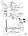
図1において、100はユーザ、アプリケーションのデータを保存するストレージ装置である。本発明のストレージ装置(100)は、ホストコンピュータ(101、300)に適合するインターフェィスを持つ。ファイバーチャネルインターフェィスを持つホストコンピュータ(300)に対しては、複数のファイバーチャネルポートからなるファイバーチャネルインターフェィス(103)で接続する。IPインターフェィスを持つホストコンピュータに対しては、複数のイーサネットポートからなるイーサネットインターフェィス(104、105)で接続する。ストレージ装置(100)の内部は、ホストコンピュータ(300)のファイバーチャネルインターフェィス(103)を接続しデータ、コマンド処理を行う、チャネルアダプタ(110)と、ホストコンピュータ(101)のイーサネットインターフェィス(104)を外部ネットワーク(102)経由で接続しファイルを含むデータ、コマンドの処理を行う、ファイルサーバボード(112、115)を持つ。ファイルサーバボード(112、115)は自らOSを持ち、ホストコンピュータ(101)からのIPプロトコルの処理、ファイルレベル要求のブロックレベル要求への変換を行うファイルサーバ部(113)とブロックレベル要求を処理するチャネルアダプタ部(114)からなる。このファイルサーバ部とチャネルアダプタ部(114)は同一ボード上に配置され、後で説明するように複数の高速なインターフェィスで接続されている。またストレージ装置(100)は、データの一時的保存とデータのリード、ライトの高速化を行うディスクキャッシュ(132)とストレージ内のデータの整合性を維持、装置内の状態を保存、共用するための制御メモリ(133)を持つ。さらにストレージ装置(100)は最終的にデータを保存するディスク(160、161)を制御するディスクアダプタ(140、142)を持つ。チャネルアダプタ(110)、ファイルサーバボード(112)、ディスクキャッシュ(132)、制御メモリ(133)ディスクアダプタ(140、142)は相互結合網(130)とのインターフェィスを持ち、お互いに結合されている。相互結合網(130)はスイッチ等で構成されており、外部ネットワーク(102)に比べ高速、かつ高信頼なネットワークになっている。以上の構成により本発明のストレージ装置は、同一装置で複数のインターフェィスを持つので、図3に示したように余計なファイルサーバを用意する必要がなく、装置コストを下げることが可能となる。次にファイルサーバボード(112、115)の詳細について説明する。
【0029】
図2は本発明におけるファイルサーバ部とチャネルアダプタ部を統合した、ファイルサーバボードの構成図である。
【0030】
図2において、200は外部ネットワーク(102)を通して、ホストコンピュータとファイルレベルのコマンド、データの送受信を行い、相互結合網(130)を通して、ディスクキャッシュ(132)、制御メモリ(133)ディスクアダプタ(140、142)とブロックレベルのコマンド、データの送受信を行う、ファイルサーバボード(112、115)の基本構成を示している。なお図2では説明を容易にするため、外部ネットワーク(102)、相互結合網(130)とのインターフェィス数は1個に限定してあるが、それらが複数存在する場合も当然本特許の範囲にある。201はファイルサーバ部であり、外部ネットワーク(102)からのコマンド、データを受け取り、自ファイルシステム内の処理を行った後、ブロックレベルのデータ、コマンドの変換処理を行いチャネルアダプタ部(202)へ送る。210はサーバプロセッサであり、ファイルサーバ部(201)の全体を制御する。211はホストコントローラであり、サーバプロセッサ(210)と周辺のメモリ、内部バス(214)のデータ、コマンド、割り込み信号の送受信、障害情報の制御を行う。212はLANコントローラであり、外部ネットワーク(102)から来るデータ、コマンドの制御を行う。213はイーサネットであり、外部ネットワーク(102)とファイルサーバボード(200)を接続し、IPプロトコルに準拠したデータ、コマンドの伝送を行う。214は内部バスであり、ホストコントローラ(211)、LANコントローラ(212)、チャネルアダプタ部(202)を接続し、データ、コマンドの送受信を行う。内部バス(214)以外に、サーバプロセッサ(210)、ホストコントローラ(211)は、障害情報の送受信を独立に行うパスとして、管理バス(230)を持つ。管理バス(230)はチャネルアダプタ部(202)内の制御データコントローラ(221)に接続されており、障害のため内部バス(214)使えない場合でも、サーバプロセッサ(210)、ホストコントローラ(211)の障害情報をチャネルアダプタ部(202)に転送する。202はチャネルアダプタ部であり、ファイルサーバ部(201)から送られた、ブロックレベルのデータ、コマンドを受け取り、内容に応じて相互結合網(130)を通して適当なディスクキャッシュ(132)、制御メモリ(133)、ディスクアダプタ(140、142)に送信する。220はチャネルプロセッサであり、上記チャネルアダプタ部(202)の全体を制御する。221は制御データコントローラであり、ストレージ装置(100)全体を制御するために必要なデータの送受信の制御、サーバプロセッサ(210)、ホストコントローラ(211)からの障害情報の送受信の制御を行う。222は制御メモリ(133)用の相互結合網(130)であり、制御データコントローラからの制御データを制御メモリ(133)、ディスクアダプタ(140、142)、他のチャネルアダプタ(110)、ファイルサーバボード(113)へ転送する。223はネットワークデータコントローラであり、ユーザまたはアプリケーションのデータの送受信を制御する。224はユーザ、アプリケーションデータ転送用の相互結合網(130)であり、ネットワークデータコントローラ(223)からのデータをディスクキャッシュ(132)、ディスクアダプタ(140、142)に転送する。231は制御データパスであり、コマンドやストレージ装置(100)全体を制御するために必要な情報をファイルサーバ部(201)とチャネルアダプタ部(202)間で送受信する。232はネットワークデータパスであり、ユーザまたはアプリケーションのデータやデータ転送に必要なパラメータ等をファイルサーバ部(201)とチャネルアダプタ部(202)間で送受信する。250は管理ネットワークであり、チャネルプロセッサ(220)で収集した障害情報、構成情報を管理プロセッサ(255)に転送するために利用する。管理プロセッサ(255)は受信した情報より、障害処理、構成変更等を判断し、必要であればストレージ装置(100)に指示を行う。また管理プロセッサ(255)は各ボードの情報を管理ディスプレイ(260)に一元的に表示することが可能である。たとえば261のような管理表を表示することが可能であり、ボード#(265)毎にファイルサーバ部(266)、チャネルアダプタ部(267)の状態を表示することが可能となる。240はファイルサーバボード(200)の電源でありここから、ファイルサーバ部(201)、チャネルアダプタ部(202)に対して電源を供給する。以上に述べた構成によって、同一ボード上にファイルサーバとストレージ装置のインターフェィスをまとめることが可能となり、装置の設置面積が削減する。またファイルサーバとストレージ装置を同一管理プロセッサ(255)、管理ディスプレイ(260)上で管理することも可能となり、管理コストが削減する。さらにファイルサーバ部(201)とチャネルアダプタ部(202)間のデータ、コマンド転送に関して、制御データパス(231)とネットワークデータパス(232)の2種類の独立したパスを設けることにより、コマンド、パラメータなどの比較的短いデータと、ユーザ、アプリケーションデータなどの比較的長いデータを分離して処理することにより、データ転送性能を上げることが可能になる。またコマンド等をまとめて転送することもでき、処理効率を上げることが可能となる。さらにコマンドとデータを分離することにより、コマンドのフォーマットを標準仕様から変更できるので装置特有な情報、パラメータをチャネルアダプタに直接伝えることも可能となり、ディスクキャッシュ(132)内の常駐データの選別などが可能となる。この2種類の独立したパスは、物理的に分離した2本のパスで構成する場合と、以下に述べるファイルサーバボード(112)のハード構成図のように物理的には1本のパスにて、論理的に2本のパスがあるように制御を行う方式のどちらを使っても実装可能であるがそれらが本特許の範囲にあることは明らかである。また図2ではファイルサーバボード(112)上にサーバプロセッサ(210)、チャネルプロセッサ(220)の2種類のプロセッサが稼動している例を挙げたが、この形態以外にサーバプロセッサ(210)のみでファイルサーバボード(112)上の部品をすべて制御する方式も実装可能であり、それも本特許の範囲であることは明らかである。
【0031】
図4は本発明の実施例1におけるファイルサーバボードのハード構成図である。
【0032】
図4においてファイルサーバ部(400)内のサーバプロセッサ(210)とホストコントローラ(211)の間は、ホストバス(413)で接続されている。ホストコントローラ(211)には管理バス(555)を制御する管理バスコントローラ(512)とサーバプロセッサ(210)のプログラム、データ等を格納するローカルメモリ(410)と内部バス(214、225)を接続し制御する内部バスコントローラ(511)が接続されている。内部バスコントローラ(411)はファイルサーバ部(400)とチャネルアダプタ部(460)間を接続するパスを制御し、論理的に複数のパスがあるように内部バス(214、225)を制御する。つまり図3における制御データパス(231)とネットワークデータパス(232)を論理的に構成することが可能となる。チャネルアダプタ部(460)内のチャネルプロセッサ(220)はローカルバスコントローラ(470)を介してローカルバス(471)に接続されている。図4では省略されているが、ローカルバスにはチャネルプロセッサ(220)に必要なメモリ等が接続されている。またローカルバスコントローラ(470)は管理ネットワーク(250)と接続されており、必要な管理情報等を管理プロセッサ(225)に送信している。ローカルバス(471)には制御データコントローラ(221)が接続されている。制御データコントローラ(221)には内部バス(255)が接続されており、通常の制御データの送受信が行われる。また相互結合網(222)を通して制御メモリ(131)、他のチャネルプロセッサと接続されており、制御情報、共有情報を送受信している。さらにサーバプロセッサ(210)、管理バスコントローラ(225)からの割り込み信号(456,457)が直接入力される。また、内部バス(214、225)が障害等で稼動していない場合にもサーバプロセッサの情報が入手できるように、管理バス(455)も接続されている。制御データコントローラ(221)内部には、通常制御を行うための通常レジスタ(480)、エラー情報を記憶するためのエラーレジスタ(481)、ファイルサーバ部(400)との通信制御を行うためのドアベルレジスタ(482)、通信メモリ(483)がある。内部バス(225)には制御データコントローラ(221)以外にネットワークデータコントローラ(223)が接続されており、ユーザ、アプリケーションデータを送受信する。また、チャネルプロセッサ(220)がファイルサーバ部(400)の起動、停止、再起動を制御できるように、制御データコントローラ(221)と管理バスコントローラ(225)は、電源制御手段(458)で接続されている。本実施例では、電源制御手段(458)によってファイルサーバ部の電源を制御できるものとする。図4の構成はあくまでもひとつの実現例であり、他の構成でも本特許の範囲にあることは自明である。次に以上のべたファイルサーバボード(200)内にある制御データパス(231)を使って送受信されるコマンドの構造例を示す。
【0033】
図5は本発明の実施例1のコマンドデータブロックのフォーマットを示す図である。
【0034】
図5において、500はファイルサーバ部(400)からチャネルアダプタ部(202)に送信されるコマンドデータブロックを示している。501はコマンドの種別であり、通常のコマンドか特殊なコマンドなのかを区別する。502、510、535、540はリザーブ領域で特に意味はない。503はTAG種別であり、キューに格納された場合の制御方法を指示する。504はサーバプロセッサ#であり、このコマンドを発行したサーバプロセッサ(210)を特定する。505はIIDであり、ユーザ領域またはシステム領域へのアクセスを区別する。506はLUNであり、サーバプロセッサ(210)がアクセスする先の論理ユニットの番号である。511はTAG#をであり、キューの内部での識別番号を示す。515はCDBであり、通常のSCSIで使われるフォーマットに準拠したコマンドが入る。516はCDB内のオペコードであり、リード、ライト等のコマンドを区別する。520はイニシエータポート番号であり、外部にコマンドを送信する場合の送信元のポートの区別を行う。525は外部デバイスWWNであり、外部にコマンドを送信する場合の送信先WWNを示す。530は外部デバイスLUNであり、外部にコマンドを送信する場合の送信先LUNを示す。541はアドレスエントリ数を示し、以下に続くストレージ装置(100)へ指示するパラメータの個数を示す。545、560はLBA1、LBA2であり、LU内での相対的なアドレスを示す。550、565はサーバプロセッサ(210)のローカルメモリ(410)内での物理アドレスを示し、対象とするデータの格納位置となる。555、570はストレージ装置指示パラメータであり、ファイルサーバ部内に特有な情報をここに置きチャネルアダプタに伝える。551、571は各パラメータに対応するデータのバッファサイズまたは転送データ長を示す。ストレージ装置指示パラメータの例としては、ディスクキャッシュ(132)へのデータ常駐指示がある。これを用いることにより、ストレージ装置(100)だけでは知ることのできないユーザ、アプリケーションデータの使用頻度等をつかむことが可能となり、ストレージ装置(100)の性能向上につなげることが可能になる。以上述べた、コマンドデータブロックが、サーバプロセッサ(210)、制御データコントローラ(221)、チャネルプロセッサ(220)、ディスクキャッシュ(132)間でどのように送受信されるかについて以下に説明する。
【0035】
図6は、本発明の実施例1のデータアクセス時のフローチャートを示す図である。
【0036】
サーバプロセッサ(210)、チャネルプロセッサ(220)はコマンドを効率よく処理するためにそれぞれコマンドキュー(CmdQueue)(602、607)、キューの先頭を示すポインタ(CmdHead)(601、606)、次に来るコマンドを格納すべき位置を示すポインタ(CmdNext)(603、608)を持つ。コマンドキュー(602、607)はリングバッファになっている。またコマンド終了後のステータスの管理のために、ステータスキュー(StQueue)(632、637)、キューの先頭を示すポインタ(StHead)(631、636)、次に来るコマンドを格納すべき位置を示すポインタ(StNext)(633、638)を持つ。ステータスキュー(StQueue)(632、637)もリングバッファとなっている。コマンド、データ転送時に、サーバプロセッサ(210)、チャネルプロセッサ(220)間でコマンドキュー(CmdQueue)(602、607)の内容を随時確認している。両者において、 CmdHead(601、606)と、CmdNext(603、608)の内容は一致している必要がある。そのため、制御データコントローラ(221)を通してCmdHead(606)、CmdQueue(602)、CmdNext(603)をそれぞれ、サーバプロセッサ(210)、チャネルプロセッサ(220)、チャネルプロセッサ(220)に転送し、整合性をとる。同様な処理はステータスキュー(StQueue)(632、637)にも必要であり、サーバプロセッサ(210)、チャネルプロセッサ(220)間でステータスキュー(StQueue)(632、637)の内容の確認を随時行う。コマンド、データ処理を行うために、サーバプロセッサ(210)のプロセス(600)で、以下、3ステップの処理が行われる。
(1) コマンドキュー(CmdQueue)(602)に空きがあることを確認後、コマンドを格納。
(2) キューポインタを更新し、CmdNext(603)を見てリングバッファが溢れないように制御。
(3) ポーリングを開始し、ステータスキューの更新をチェック。
このプロセスに対して、チャネルプロセッサ(220)のプロセス(605)で以下の5ステップの処理が行われる。
(4) ポーリングにより、コマンドキュー(CmdQueue)(607)の更新をチェック。
(5) コマンドキューCmdQueue)(607)の内容をDMA転送にて、受信。
(6) ポーリングにより、ステータスキュー(StQueue)(637)の更新をチェック。
(7) キューの先頭を示すポインタ(CmdHead)(606)を更新。
(8) 各コマンドを処理。
【0037】
次にサーバプロセッサ(210)のプロセス(610)にてコマンド処理に必要なパラメータ(611)をDMA転送にて、制御データコントローラ(221)を通してチャネルプロセッサ(220)に転送する。また同時にサーバプロセッサ(210)のプロセス(620)にてデータをDMA転送にて、ネットワークデータコントローラ(223)を通してディスクキャッシュ(132)に転送する。プロセス(610)とプロセス(620)は、図3、4で示したように独立したパスにて処理できるので、並列に処理を進めることが可能である。データ転送処理が完了した後、チャネルプロセッサ(220)のプロセス(635)にて以下の2ステップの処理が行われる。
(9) 実行結果をステータスキュー(StQueue)(637)に格納。
(10) ドアベルレジスタ(582)セットし割り込みを発生。
このプロセスに対して、サーバプロセッサ(210)のプロセス(630)で、以下の3ステップの処理が行われる。
(11) 割り込みまたはポーリングより、ステータスキュー(StQueue)(632)の更新を検知
(12) ステータスの取り出し
(13) キューのポインタ(StNext)(633)の更新
以上のフローチャートに示したように、コマンド、ステータス毎にキューを持つことが可能となり、また各々、独立のパスを用いて処理できるので、データアクセス性能を向上することが可能となる。
【0038】
図7は、本発明の実施例1のサーバプロセッサ障害発生時のフローチャートを示す図である。
【0039】
図7において、700はサーバプロセッサ(210)に障害が発生し、例外処理を行う必要があることを示す。ここで、通常コマンド、データが送受信される、内部バス(214、225)と内部バスコントローラ(411)は正常に動作することが期待できない。障害情報はプロセス(810)にて例外ハンドラの処理が進み、エラー報告がプロセス(715)にて制御データコントローラ(221)のエラーレジスタ(482)に割り込み信号で記録される。その後サーバプロセッサ(210)はリセット命令を待つことになる。次に制御データコントローラ(221)はプロセス(715)でサーバプロセッサ(210)に障害が発生していることをエラー割り込みの形でチャネルプロセッサ(220)に伝える。チャネルプロセッサ(220)のプロセス(720)ではエラー割り込みを受けてエラー処理関数が起動する。その後チャネルプロセッサ(220)はサーバプロセッサ(210)を初期化するために、プロセス(715)にて制御データコントローラ(221)の通常レジスタ(483)にリセット命令を送信する。制御データコントローラ(221)は次にサーバプロセッサ(210)にリセットを割り込み信号にて送信する。リセットを受けたサーバプロセッサ(210)のプロセス(710)は次のプロセス(725)にて再起動を行う。プロセス(725)ではサーバプロセッサ(210)内の障害要因を収集して、プロセス(730)にて制御データコントローラ(221)の通信メモリ(481)に格納する。ただしこの障害要因は通常パスを通して転送されるので、正しい値である保障はない。プロセス(725)はこれらの情報の格納が終了した後、退避完了報告をドアベルレジスタ(482)経由でチャネルプロセッサ(220)に伝える。その後、チャネルプロセッサ(220)は正しい障害情報を確保するために、プロセス(750)、プロセス(715)において管理バス(455)経由で障害情報を読み出す。具体的にはチップセットレジスタリードを行う。また同時にプロセス(745)にて制御データコントローラ(221)の通信メモリ(481)に格納された障害要因も読み出す。これらの情報を読み出した後、チャネルプロセッサ(220)は管理プロセッサ(255)へ情報を報告し、処理指令を受領する。次に制御メモリ(131)へ障害情報転送し、他のボードに障害処理要求を出す。次にプロセス(755)にて内部バス(214、225)のエラーが発生しているかどうかをチェックする。エラーがなければ、チャネルプロセッサ(220)はプロセス(770)にてメモリダンプの指示をネットワークデータコントローラ(223)に対して行う。ネットワークデータコントローラ(223)は、ローカルメモリ(410)の情報等をプロセス(765)にてDMA転送にてメモリダンプする。もし内部バス(214、225)にエラーが発生していた場合、メモリダンプは行わない。次にチャネルプロセッサ(220)は外部からの障害発生ファイルサーバボード停止要求に応じて、プロセス(790)にて制御データコントローラ(221)に対して強制停止命令を発行する。制御データコントローラ(221)は電源制御手段(458)によって、サーバプロセッサ(210)を強制停止させる機能を持っており,上記強制停止命令を受けて,サーバプロセッサ(210)は強制閉塞する。以上の処理では、通常のバス以外に障害情報を送信するパスを設けているので、バスに障害があった場合でも障害情報をチャネルプロセッサ(220)に対して送信でき、障害処理の高信頼化を図ることが可能となる。図7では、単一ファイルサーバボード(112)内の障害情報の通信方法を示したので、これを用いて複数ファイルサーバボード(112)間でのフェイルオーバーを行う方法について以下で説明する。
【0040】
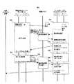
図8は、本発明の実施例1のサーバプロセッサ障害時のフェイルオーバーのフローチャートを示した図である。800は図7同様、サーバプロセッサ(210)に障害が発生し、例外処理を行う必要があることを示す。障害を感知したチャネルプロセッサ(220)は図7で説明したサーバプロセッサ障害発生時の処理を行う。その中で制御メモリ(131)に対して障害情報と障害処理要求を書き込む。その後フェイルオーバー先のファイルサーバボード(115)がプロセス(810)にて障害処理を検知する。その後ファイルサーバボード(115)は障害発生元のファイルサーバボード(112)に対して停止要求を出す。その後停止完了の通知が来るまでプロセス(815)の待ち状態に入る。ファイルサーバボード(115)からのファイルサーバボード停止要求を受けた、ファイルサーバボード(112)は図7で説明したように、サーバプロセッサを停止する。さらに、プロセス(820)で残っているI/O処理を破棄した後、制御メモリ(131)に対してファイルサーバボード(112)の停止を書き込み、チャネルプロセッサを停止する。ファイルサーバボード(112)の停止を受けた制御メモリ(131)はプロセス(825)にてストレージ装置(100)の構成情報を更新し、停止をフェイルオーバー先のファイルサーバボード(115)に通知する。停止の通知を受けた、フェイルオーバー先のファイルサーバボード(115)はプロセス(930)にてファイルサーバの引継ぎを行い、その結果を管理プロセッサ(255)に通知し、フェイルオーバーを完了する。
【0041】
以上述べた実施例により本特許に開示されたSAN/NAS統合型ストレージ装置を使うと、通常のI/O処理では、サーバプロセッサ(210)、チャネルプロセッサ(220)毎にコマンドキュー(CmdQueue)(602、607)、ステータスキュー(StQueue)(632、637)を持つことにより、非同期にコマンド処理、ステータス処理を進めることが可能になり、またコマンド、データを独立のパスを用いて処理することも可能になるので、I/O処理性能を向上できる。さらに、コマンド、データで独立なパスを使い、またコマンドを拡張することにより、ファイルサーバ固有のI/O特性をストレージ装置に伝えることが可能となり、ディスクキャッシュ(132)のヒット率の向上等のストレージ装置(100)最適化が図れる。さらに同一ボード上にファイルサーバ、ディスク制御装置のチャネルアダプタがあり、同一の管理プロセッサ(255)、管理ディスプレイ(260)で管理することが可能になるので、設置面積の減少、管理コストの削減ができる。障害処理では、管理バス(455)から障害情報を送信し、ストレージ装置(100)で共有している制御メモリ(131)に書き込むことで、バスの障害にかかわらず、他のファイルサーバボードに対して早く障害情報を伝えることが可能となり、フェィルオーバーの効率を上げ、信頼性を向上できる。
【0042】
(実施例2)
図9は、本発明の実施例2のサーバプロセッサ障害時のフェイルオーバのフローチャートを示す図である。
図8では、障害発生元のファイルサーバボード(112)が自立的に障害発生をフェイルオーバー先のファイルサーバボード(115)に通知したが、障害のよっては通知ができない場合があり、障害処理が開始できない。このようなケースを避けるため、フェイルオーバー先のファイルサーバボード(115)が積極的に他のファイルサーバボード(112)を監視する方式が考えられる。正常な場合、ファイルサーバボード(112)は一定時間間隔でハートビートをフェイルオーバー先のファイルサーバボード(115)に伝える。もしプロセス(900)のように、障害が発生して一定時間内にこのハートビートが通知されない場合、フェイルオーバー先のファイルサーバボード(115)は障害が発生と判断し、プロセス(905)のように障害処理を開始する。障害発生元のファイルサーバボード(112)が障害情報を制御メモリ(131)に書き込んだ後、フェイルオーバー先のファイルサーバボード(115)は制御メモリ(131)に構成情報を読み出し、障害が発生したことを確認し障害処理内容を確定する。その後プロセス(905)にてファイルサーバボード(115)は障害発生元のファイルサーバボード(112)に対して停止要求を出す。その後の処理は図8と同様に、その後停止完了の通知が来るまでプロセス(920)の待ち状態に入る。ファイルサーバボード(115)からのファイルサーバボード停止要求を受けた、ファイルサーバボード(112)は図7で説明したように、サーバプロセッサを停止する。さらに、プロセス(925)で残っているI/O処理を破棄した後、制御メモリ(131)に対してファイルサーバボード(112)の停止を書き込み、チャネルプロセッサを停止する。ファイルサーバボード(112)の停止を受けた制御メモリ(131)はプロセス(930)にてストレージ装置(100)の構成情報を更新し、停止をフェイルオーバー先のファイルサーバボード(115)に通知する。停止の通知を受けた、フェイルオーバー先のファイルサーバボード(115)はプロセス(935)にてファイルサーバの引継ぎを行い、その結果を管理プロセッサ(255)に通知し、フェイルオーバーを完了する。
以上述べた実施例により、開示されたSAN/NAS統合型ストレージ装置を使うと、障害発生元のファイルサーバボード(112)から障害発生の送信ができない場合でも早い段階でフェイルオーバー先のファイルサーバボード(115)が障害発生の検知、確認を行うことが可能となり、フェィルオーバーの効率を上げ、信頼性を向上できる。
【0043】
【発明の効果】
本発明によれば、ファイルサーバとディスク制御装置間のI/Oコマンド、データの送受信を独立して行えるため、I/O処理性能が向上できるという効果がある。またアプリケーション、ファイルシステムのI/O特性情報をディスク制御装置に与えることができるため、I/O処理の最適化ができるという効果がある。また同一のボード上にファイルサーバとディスク制御装置のチャネルアダプタを実装し、統一した管理プロセッサ、管理プロセッサで管理するために、装置の設置面積の減少、管理コストの削減ができる効果がある。また、独立した経路でファイルサーバの障害情報を共有できるため、フェイルオーバーの効率化、高信頼化ができるという効果がある。
【図面の簡単な説明】
【図1】本発明のSAN/NAS統合型ストレージシステムの構成図。
【図2】本発明におけるファイルサーバ部とチャネルアダプタ部を統合した、ファイルサーバボードの構成図。
【図3】比較例のSAN/NAS統合型ストレージシステムの構成図。
【図4】実施例1におけるファイルサーバボードのハード構成図。
【図5】実施例1のコマンドデータブロックのフォーマットを示す図。
【図6】実施例1のデータアクセス時のフローチャートを示す図。
【図7】実施例1のサーバプロセッサ障害発生時のフローチャートを示す図。
【図8】実施例1のサーバプロセッサ障害時のフェィルオーバーのフローチャートを示す図。
【図9】実施例2のサーバプロセッサ障害時のフェィルオーバーのフローチャートを示す図。
【符号の説明】
100、101、150、151:ファイバチャネルインターフェィス、 102:イーサネットインターフェイス、 110:チャネルアダプタ、112:ファイルサーバボード、113:ファイルサーバ部、114:チャネルアダプタ部、 130:相互結合網、 131:ディスクキャッシュ、 132:制御メモリ、 140、142:ディスクアダプタ、 160,161:ドライブ。[0001]
TECHNICAL FIELD OF THE INVENTION
The present invention relates to a device in which a file system and a storage system are integrated and a management method thereof, and more particularly to a technique for processing I / O commands and failure processing from a file system at high speed.
[0002]
[Prior art]
[Patent Document 1]
JP-A-2000-99281
[Patent Document 2]
JP 2002-14878 A
[Non-patent document 1]
US Patent Publication 2002/0116593
2. Description of the Related Art Conventionally, as a storage device used by being connected to a host computer, there is one disclosed in Japanese Patent Application Laid-Open No. 2000-99281. This is a configuration in which a channel adapter connected to a host computer, a disk adapter connected to a disk device, a disk cache, and a control memory are connected by an interconnection network in order to speed up data transfer and control in the storage device. Take.
[0003]
In addition, a file server in the storage device and a host computer are connected by Ethernet so that a user who has only an Ethernet (registered trademark) port can connect, and a fiber channel port block interface is provided between the file server and the channel adapter. Is disclosed in, for example, US Patent Application 2002/0116593.
[0004]
Note that a method of performing communication between a server and storage using a dedicated network, for example, using a fiber channel protocol, is generally referred to as a SAN (Storage Area Network). In addition, a method of directly connecting to a LAN and performing communication using a protocol based on a standard such as a TCP / IP protocol or “Ethernet II” (Ethernet is a registered trademark) “IEEE802.3” or “IEEE802.2” via Ethernet, for example, is used. Generally, it is referred to as NAS (Network Area Storage).
On the other hand, as a computer system having a path for transmitting fault information directly from a file server to a storage device, there is a method disclosed in, for example, JP-A-2002-14878.
[0005]
[Problems to be solved by the invention]
An object of the present invention is to provide a new system in which SAN / NAS is integrated and integrated.
[0006]
FIG. 3 is a system configuration diagram created as a comparative example of the present invention. This system is a SAN / NAS integrated storage system in which a mutual connection network is applied and a file system and a storage system are integrated and integrated.
[0007]
Generally, in order for a user or an application to access data, it is necessary to use a host computer (300), a file server (310), and a storage device (340) as shown in FIG. In this case, the user and the application exist in the host computer (300), and issue a data access request from the host computer (300) via the network or the Ethernet port (305) to the file server (310) that manages the file. The file server (310) manages data (files) recognized by the user and the application, and issues data (block) read / write requests to the disks (160, 161). At this time, the file server (310) converts the file information into block information. The disks (160, 161) store and read data according to commands from the file server (310).
In such a storage device (340), with the increase in the capacity of the disks (160, 161), the improvement in interface performance and processor performance, and the increase in the mounting density of LSIs and boards, the integration of hardware has been promoted. ing. Accordingly, the number of channel adapters and the number of disks increase, and the channel adapters (110, 310), the disk adapters (140, 141), the disk cache (132), and the control memory are used to speed up data transfer and control in the storage device. It is advantageous to adopt a configuration in which the interconnections (131) are connected by an interconnection network (130). As a storage device having an interconnection network, there is a method disclosed in the above-mentioned JP-A-2000-99281.
[0008]
On the other hand, demands for reduction in management costs have led to the aggregation of a plurality of user data into the storage device (340). However, not all users have a block interface represented by Fiber Channel, and many users often have only an IP interface represented by Ethernet. In addition, when connecting to the storage device (340) from a remote area, there is a problem in that the cost increases when the fiber channel is used. Therefore, as shown in FIG. 3, in order to promote the integration of the storage device (340), a file server is built in the storage device (340) so that even a user having only an IP interface such as an Ethernet port (305) can connect. There is an increasing demand for a storage device (340) in which a file server (310) is placed in a storage device (340) and connected to a channel adapter (330) by a block interface such as a fiber channel port (320).
[0009]
As a NAS having such an IP interface, for example, there is a method disclosed in US Patent Application 2002/0116593. The storage device disclosed in this patent application has a file server that controls an IP interface for a user, and is connected to the storage device by a fiber channel via a mutual switch. According to this method, the file server processing and the storage processing are performed separately, so that high performance can be achieved.
[0010]
On the other hand, when the scale of the storage device increases and NAS becomes general, it is necessary to cooperate with failure processing between the file server (315) and the storage device (340) in order to maintain high reliability of the entire system. come. In particular, if the information is not transmitted directly to the storage device (340) at the time of failure on the file server side (315), it takes time to separate the failed part and to fail over to another part, so that reliability and reliability can be increased. The performance decreases. For this reason, a method of transmitting fault information using a different path for fault information separately from a path through which normal data passes is being studied. As such a computer system having a path for directly transmitting fault information from a file server to a storage device, there is a method disclosed in, for example, JP-A-2002-14878. The computer system disclosed in this publication does not use a host bus controlled by a processor on the file server side, and employs a configuration having a separate path for communicating failure information to a storage device. According to this method, a failure on the file server side can be directly known irrespective of the state of the processor, and high reliability of the system can be maintained.
[0011]
However, in the storage device disclosed in JP-A-2000-99281, the interface with the host computer does not include the IP interface. Therefore, a user who does not have a file server cannot connect to this storage device. Therefore, it is necessary to prepare a new file server to connect to this storage device. FIG. 3 shows an example in which a file server (310) is newly provided. However, this comparative example has a problem that the management cost and the installation area increase.
[0012]
In the NAS device disclosed in US Patent Application No. 2002/0116593, since a NAS is provided in the device, a file server and a storage device are connected. However, a connection used to transfer data and commands once. The path is a single Fiber Channel cable, and when the load is high, there is a high possibility that the performance will be degraded. Further, since the connection is made only by the fiber channel cable, when a failure occurs in the file server, the failure information cannot be transmitted to the storage device. Therefore, it is highly likely that much time will be required to complete the failover. In other words, this NAS device has problems of performance degradation and reliability degradation.
[0013]
On the other hand, a computer system disclosed in Japanese Patent Application Laid-Open No. 2002-14878 concerning failure processing has a file server (referred to as an I / O processor in the known example) directly on the disk controller side (referred to as a main processor in the known example). The failure information can be transmitted, but the information is used for failure processing only after the setting information of the file server is changed and transmitted to an external management server through the IP network, so that the load on the IP network is high. In such a case, there is a problem that the other party cannot acquire the failure information accurately or it takes time to transmit the failure information.
Accordingly, an object of the present invention is to provide a system having a file server interface in a storage device and a method thereof.
[0014]
Another object of the present invention is to provide a system and a method for processing commands and data in parallel between a file server and a storage device.
[0015]
Still another object of the present invention is to provide a system and method for transferring failure information of a file server to a storage device separately from normal commands and data, and sharing the information with the entire storage device.
[0016]
Still another object of the present invention is to provide a system and a method for performing failover of a failed file server using failure information shared by storage devices.
[0017]
[Means for Solving the Problems]
In order to solve the above problem, in a storage device according to one embodiment of the present invention, a disk for storing data, a first adapter directly connected to a first network connected to a first host computer, and a disk A first adapter, a first adapter, and a second network directly connected to and coupled to the second adapter, wherein the first adapter is connected to the host via the first network. The information according to the protocol received from the computer is converted into the information according to the second protocol and transferred to the second adapter via the second network. According to the present invention, the host computer and the adapter can be connected by a high-speed interface that does not perform redundant protocol conversion by using an internal bus such as a PCI interface. In particular, in the present invention, the file server and the channel adapter of the storage device are placed on the same substrate as the first adapter, so that they can be connected by a high-speed interface.
[0018]
The first protocol is a so-called Ethernet protocol based on, for example, any of the standards of “Ethernet II”, “IEEE802.3” and “IEEE802.2”, and enables connection with various host computers. The second protocol is, for example, a fiber channel, and can realize a dedicated high-speed channel. According to the present invention, the two can be connected only by the first adapter. Therefore, it is excellent in space factor and maintenance.
[0019]
The file server unit has a server processor that controls the file server unit, a LAN controller that controls data and commands coming from the first network, and a first internal bus that connects the server processor and the LAN controller. For example, the server processor performs data and command conversion processing and sends the data and command to the channel adapter unit according to the second protocol. The channel adapter unit sends the converted data and command to the second network.
[0020]
In this way, by integrating the file server unit and the channel adapter unit, a network data path for transmitting and receiving data and a control data path for transmitting and receiving commands are physically and logically independent between the two. It can be easily provided. That is, a plurality of independent paths are provided between the file server and the storage device so that data and commands can be processed by different paths during I / O processing.
[0021]
Further, the file server unit may include a host controller for transmitting and receiving data and commands between the server processor and the first internal bus, and controlling fault information. Further, the channel adapter unit may include a channel processor that controls the channel adapter unit. It is desirable to provide a management bus between the file server unit and the channel adapter unit for transmitting and receiving fault information without passing through the first internal bus. This management bus directly connects, for example, a server processor or a host controller and a control data controller in a channel adapter unit. Even when the first internal bus cannot be used due to a failure, the failure information of the server processor or the host controller can be transferred to the channel adapter unit. In this way, the failure processing information of the file server can be transferred to the storage device using a path different from the I / O processing. Further, the failure processing information is stored in a memory so that it can be shared by the storage system, and can be referred to from another storage device or a file server that performs a failover.
[0022]
Another aspect of the present invention is the novel first adapter described above, which is, for example, in accordance with one of the standards "Ethernet II", "IEEE 802.3" and "IEEE 802.2" (referred to as "external protocol"). A disk controller that sends and receives commands and data to and from a host computer according to a protocol based on the protocol, and accesses a recording disk according to a protocol other than an external protocol (referred to as an “internal protocol”). A file server unit and a channel adapter unit are provided above.
[0023]
The file server unit controls the file server unit, converts a data and a command from an external protocol to an internal protocol, and performs a conversion process of a command, a LAN controller that controls communication of data and a command by an external protocol, a server processor, and the LAN controller. And a host controller between the server processor and the first internal bus for transmitting and receiving data and commands and controlling fault information.
[0024]
A channel data controller for controlling transmission and reception of data to and from the recording disk; a control data controller for controlling transmission and reception of commands to and from the recording disk; a channel processor for controlling the channel adapter; A second internal bus that connects the data controller and the control data controller, and is connected to the first and second internal buses between the file server unit and the channel adapter unit to transfer data based on an internal protocol; A network data path for transmitting and receiving, and a control data path connected to the first and second internal buses for transmitting and receiving commands based on an internal protocol, independently of each other physically or logically; And a management bus for transmitting and receiving fault information without passing through an internal bus.
[0025]
A storage device according to still another aspect of the present invention includes a plurality of disks that store data, a plurality of control devices that receive an I / O command from a host computer and control the disk according to the I / O command, An interconnection network for coupling a plurality of control means, wherein one of the control devices has a block interface as an interface with a host computer, and another of the control devices has a file interface as an interface with the host computer. It has an interface. Here, the file interface (file system interface) refers to an interface for transmitting and receiving data based on a file name. The block interface (block device interface) refers to an interface for transmitting and receiving data based on a device identifier represented by SCSI, a head block address, the number of blocks, and the like, and is a block indicating a data position in a disk. Access data by specifying an address. As described above, a person who provides a storage device integrating interfaces handling different protocols.
[0026]
BEST MODE FOR CARRYING OUT THE INVENTION
Hereinafter, an embodiment of the present invention will be described with reference to FIG.
[0027]
FIG. 1 is a configuration diagram of a first embodiment of the present invention.
[0028]
In FIG. 1,
[0029]
FIG. 2 is a configuration diagram of a file server board in which a file server unit and a channel adapter unit according to the present invention are integrated.
[0030]
In FIG. 2,
[0031]
FIG. 4 is a hardware configuration diagram of the file server board according to the first embodiment of the present invention.
[0032]
In FIG. 4, a host bus (413) is connected between a server processor (210) in a file server unit (400) and a host controller (211). The host controller (211) is connected with a management bus controller (512) for controlling the management bus (555), a local memory (410) for storing programs and data of the server processor (210), and an internal bus (214, 225). And an internal bus controller (511) for controlling the operation. The internal bus controller (411) controls a path connecting the file server unit (400) and the channel adapter unit (460), and controls the internal buses (214, 225) so that there are logically a plurality of paths. That is, the control data path (231) and the network data path (232) in FIG. 3 can be logically configured. The channel processor (220) in the channel adapter section (460) is connected to the local bus (471) via the local bus controller (470). Although not shown in FIG. 4, a memory and the like necessary for the channel processor (220) are connected to the local bus. The local bus controller (470) is connected to the management network (250) and transmits necessary management information and the like to the management processor (225). The control data controller (221) is connected to the local bus (471). An internal bus (255) is connected to the control data controller (221), and normal control data is transmitted and received. Further, it is connected to a control memory (131) and another channel processor through an interconnection network (222), and transmits and receives control information and shared information. Further, interrupt signals (456, 457) from the server processor (210) and the management bus controller (225) are directly input. Also, a management bus (455) is connected so that information of the server processor can be obtained even when the internal buses (214, 225) are not operating due to a failure or the like. Inside the control data controller (221), a normal register (480) for performing normal control, an error register (481) for storing error information, and a doorbell for controlling communication with the file server unit (400) There are a register (482) and a communication memory (483). A network data controller (223) is connected to the internal bus (225) in addition to the control data controller (221), and transmits and receives user and application data. Also, the control data controller (221) and the management bus controller (225) are connected by a power control means (458) so that the channel processor (220) can control the start, stop, and restart of the file server unit (400). Have been. In the present embodiment, it is assumed that the power of the file server unit can be controlled by the power control unit (458). The configuration of FIG. 4 is merely one example of implementation, and it is obvious that other configurations are also within the scope of the present invention. Next, an example of the structure of a command transmitted and received using the control data path (231) in the solid file server board (200) will be described.
[0033]
FIG. 5 is a diagram illustrating a format of a command data block according to the first embodiment of the present invention.
[0034]
In FIG. 5,
[0035]
FIG. 6 is a diagram showing a flowchart at the time of data access according to the first embodiment of the present invention.
[0036]
The server processor (210) and the channel processor (220) come next to a command queue (CmdQueue) (602, 607), a pointer (CmdHead) (601, 606) indicating the head of the queue, respectively, in order to efficiently process the command. It has a pointer (CmdNext) (603, 608) indicating the position where the command should be stored. The command queues (602, 607) are ring buffers. In order to manage the status after completion of the command, a status queue (StQueue) (632, 637), a pointer (StHead) (631, 636) indicating the head of the queue, and a pointer indicating a position where the next command should be stored (StNext) (633, 638). The status queue (StQueue) (632, 637) is also a ring buffer. At the time of command and data transfer, the contents of the command queue (CmdQueue) (602, 607) are checked at any time between the server processor (210) and the channel processor (220). In both cases, the contents of CmdHead (601, 606) and CmdNext (603, 608) need to match. Therefore, the CmdHead (606), CmdQueue (602), and CmdNext (603) are transferred to the server processor (210), the channel processor (220), and the channel processor (220) through the control data controller (221), and the consistency is checked. Take. Similar processing is necessary for the status queue (StQueue) (632, 637), and the server processor (210) and the channel processor (220) check the contents of the status queue (StQueue) (632, 637) as needed. . In order to perform command and data processing, the process (600) of the server processor (210) performs the following three steps.
(1) After confirming that there is a free space in the command queue (CmdQueue) (602), the command is stored.
(2) Update the queue pointer and control CmdNext (603) so that the ring buffer does not overflow.
(3) Start polling and check for status queue updates.
The process (605) of the channel processor (220) performs the following five steps for this process.
(4) Check the update of the command queue (CmdQueue) (607) by polling.
(5) The contents of the command queue CmdQueue (607) are received by DMA transfer.
(6) Check for update of the status queue (StQueue) (637) by polling.
(7) Update the pointer (CmdHead) (606) indicating the head of the queue.
(8) Process each command.
[0037]
Next, in the process (610) of the server processor (210), the parameters (611) necessary for command processing are transferred to the channel processor (220) through the control data controller (221) by DMA transfer. At the same time, the process (620) of the server processor (210) transfers the data by DMA transfer to the disk cache (132) through the network data controller (223). The process (610) and the process (620) can be processed by independent paths as shown in FIGS. 3 and 4, so that the processes can proceed in parallel. After the data transfer processing is completed, the following two steps of processing are performed in the process (635) of the channel processor (220).
(9) Store the execution result in the status queue (StQueue) (637).
(10) Set the doorbell register (582) and generate an interrupt.
For this process, the following three steps are performed in the process (630) of the server processor (210).
(11) Update of status queue (StQueue) (632) is detected by interruption or polling
(12) Status retrieval
(13) Update of the queue pointer (StNext) (633)
As shown in the above flowchart, it is possible to have a queue for each command and status, and each can be processed using an independent path, so that data access performance can be improved.
[0038]
FIG. 7 is a diagram illustrating a flowchart when a server processor failure occurs in the first embodiment of the present invention.
[0039]
In FIG. 7,
[0040]
FIG. 8 is a diagram illustrating a flowchart of a failover when a server processor fails according to the first embodiment of this invention. Reference numeral 800 indicates that a failure has occurred in the server processor (210) and exception processing needs to be performed as in FIG. The channel processor (220) that has detected the failure performs the processing when a failure occurs in the server processor described with reference to FIG. The failure information and the failure processing request are written into the control memory (131). Thereafter, the file server board (115) at the failover destination detects a failure process in the process (810). Thereafter, the file server board (115) issues a stop request to the file server board (112) where the failure has occurred. Thereafter, the process (815) waits until a stop completion notification is received. Upon receiving the file server board stop request from the file server board (115), the file server board (112) stops the server processor as described with reference to FIG. Further, after discarding the remaining I / O processing in the process (820), the stop of the file server board (112) is written into the control memory (131), and the channel processor is stopped. The control memory (131) having received the stop of the file server board (112) updates the configuration information of the storage device (100) in the process (825) and notifies the failover to the file server board (115) of the stop. . Upon receiving the stop notification, the failover destination file server board (115) takes over the file server in the process (930), notifies the management processor (255) of the result, and completes the failover.
[0041]
When the SAN / NAS integrated storage device disclosed in this patent is used according to the above-described embodiment, in a normal I / O process, a command queue (CmdQueue) (CmdQueue) for each server processor (210) and channel processor (220) is used. 602, 607) and the status queue (StQueue) (632, 637), it is possible to advance command processing and status processing asynchronously, and it is also possible to process commands and data using independent paths. As a result, I / O processing performance can be improved. Further, by using independent paths for commands and data, and by extending the commands, it becomes possible to convey the I / O characteristics unique to the file server to the storage device, and to improve the hit rate of the disk cache (132). The storage device (100) can be optimized. Further, since the file server and the channel adapter of the disk controller are provided on the same board and can be managed by the same management processor (255) and management display (260), the installation area can be reduced and the management cost can be reduced. it can. In the failure processing, failure information is transmitted from the management bus (455) and written to the control memory (131) shared by the storage device (100), so that it can be transmitted to other file server boards regardless of the failure of the bus. As a result, failure information can be quickly transmitted, thereby improving the efficiency of failover and improving reliability.
[0042]
(Example 2)
FIG. 9 is a diagram illustrating a flowchart of a failover when a server processor fails according to the second embodiment of this invention.
In FIG. 8, the file server board (112) of the failure origin has independently notified the occurrence of the failure to the file server board (115) of the failover destination. However, the failure may not be notified due to the failure. Can't start. In order to avoid such a case, a method in which the file server board (115) at the failover destination actively monitors another file server board (112) is considered. If normal, the file server board (112) transmits a heartbeat to the failover destination file server board (115) at regular time intervals. If the heartbeat is not notified within a certain period of time after the occurrence of a failure as in the process (900), the failover destination file server board (115) determines that the failure has occurred, and performs the processing in the process (905). Start fault handling. After the failure source file server board (112) writes the failure information to the control memory (131), the failover destination file server board (115) reads the configuration information to the control memory (131), and a failure occurs. Confirm that this is the case and determine the details of the failure processing. Thereafter, in the process (905), the file server board (115) issues a stop request to the file server board (112) where the failure has occurred. Thereafter, as in FIG. 8, the process enters a wait state of the process (920) until a notification of the completion of the stop comes. Upon receiving the file server board stop request from the file server board (115), the file server board (112) stops the server processor as described with reference to FIG. Further, after discarding the remaining I / O processing in the process (925), the stop of the file server board (112) is written to the control memory (131), and the channel processor is stopped. The control memory (131) having received the stop of the file server board (112) updates the configuration information of the storage device (100) in the process (930) and notifies the stop to the file server board (115) of the failover destination. . Upon receiving the stop notification, the failover destination file server board (115) takes over the file server in the process (935), notifies the management processor (255) of the result, and completes the failover.
According to the embodiment described above, when the disclosed SAN / NAS integrated storage device is used, even when the failure source cannot be transmitted from the file server board (112) of the failure source, the file server board of the failover destination can be obtained at an early stage. (115) can detect and confirm the occurrence of a failure, so that the efficiency of failover can be increased and the reliability can be improved.
[0043]
【The invention's effect】
According to the present invention, since I / O commands and data can be transmitted and received independently between the file server and the disk controller, there is an effect that I / O processing performance can be improved. Further, since the I / O characteristic information of the application and the file system can be given to the disk controller, there is an effect that the I / O processing can be optimized. Further, since the file server and the channel adapter of the disk controller are mounted on the same board and managed by the unified management processor and management processor, there is an effect that the installation area of the device can be reduced and the management cost can be reduced. In addition, since the failure information of the file server can be shared by an independent path, there is an effect that the efficiency of the failover can be increased and the reliability can be increased.
[Brief description of the drawings]
FIG. 1 is a configuration diagram of a SAN / NAS integrated storage system of the present invention.
FIG. 2 is a configuration diagram of a file server board in which a file server unit and a channel adapter unit according to the present invention are integrated.
FIG. 3 is a configuration diagram of a SAN / NAS integrated storage system of a comparative example.
FIG. 4 is a hardware configuration diagram of a file server board according to the first embodiment.
FIG. 5 is a diagram showing a format of a command data block according to the first embodiment.
FIG. 6 is a view showing a flowchart at the time of data access according to the first embodiment;
FIG. 7 is a diagram illustrating a flowchart when a server processor failure occurs according to the first embodiment.
FIG. 8 is a diagram illustrating a flowchart of failover when a server processor fails according to the first embodiment.
FIG. 9 is a diagram illustrating a flowchart of a failover when a server processor fails according to the second embodiment.
[Explanation of symbols]
100, 101, 150, 151: Fiber Channel interface, 102: Ethernet interface, 110: Channel adapter, 112: File server board, 113: File server unit, 114: Channel adapter unit, 130: Interconnection network, 131:
Claims (25)
Translated fromJapaneseホストコンピュータからのI/O命令を受信し,上記I/O命令に従って上記ディスクを制御する複数の制御装置と、
前記複数の制御手段を結合する相互結合網とを有し、
上記制御装置の1つは、ホストコンピュータとのインタフェースとして、ブロックインタフェースを持ち、
上記制御装置の別の1つはホストコンピュータとのインタフェースとして、ファイルインタフェースを持つことを特徴とするSAN/NAS統合型ストレージ装置。A plurality of disks for storing data,
A plurality of control devices for receiving an I / O command from a host computer and controlling the disk according to the I / O command;
Having an interconnection network for coupling the plurality of control means,
One of the control devices has a block interface as an interface with a host computer,
Another one of the control devices has a file interface as an interface with a host computer, and is a SAN / NAS integrated storage device.
上記ホストコンピュータと通信をするチャネルアダプタと、
上記ディスクを制御するディスクアダプタとを有する請求項1記載のSAN/NAS統合型ストレージ装置。The control device having the above block interface
A channel adapter for communicating with the host computer,
2. The SAN / NAS integrated storage device according to claim 1, further comprising a disk adapter for controlling the disk.
上記ホストコンピュータとの通信をするファイルサーバ部と、
上記ホストコンピュータから受信したファイルレベルのコマンド、データをブロックインタフェースに変換するファイルシステムと、
上記相互結合網とのインターフェィスを持つチャネルアダプタ部と、
上記ディスクを制御するディスクアダプタとを有する請求項1記載のSAN/NAS統合型ストレージ装置。The control device with the above file interface
A file server unit that communicates with the host computer;
A file system for converting file-level commands and data received from the host computer to a block interface,
A channel adapter unit having an interface with the interconnection network,
2. The SAN / NAS integrated storage device according to claim 1, further comprising a disk adapter for controlling the disk.
上記ホストコンピュータとの通信をするファイルサーバ部と、
上記ホストコンピュータから受信したファイルレベルのコマンド、データをブロックインタフェースに変換するファイルシステムと、
上記相互結合網と上記のインターフェィスを持つチャネルアダプタ部を、
単一のボード上に実装することを特徴とする請求項1記載のSAN/NAS統合型ストレージ装置。The control device with the above file interface
A file server unit that communicates with the host computer;
A file system for converting file-level commands and data received from the host computer to a block interface,
A channel adapter unit having the interconnection network and the interface,
The SAN / NAS integrated storage device according to claim 1, wherein the storage device is mounted on a single board.
上記ホストコンピュータとの通信をするファイルサーバ部と、
上記ホストコンピュータから受信したファイルレベルのコマンド、データをブロックインタフェースに変換するファイルシステムと、
上記ファイルシステムから発行されたブロックレベルのコマンド、データを受信するチャネルアダプタ部と、
上記ディスクを制御するディスクアダプタとを有する請求項1記載のSAN/NAS統合型ストレージ装置。The control device with the above file interface
A file server unit that communicates with the host computer;
A file system for converting file-level commands and data received from the host computer to a block interface,
A channel adapter unit for receiving block-level commands and data issued from the file system,
2. The SAN / NAS integrated storage device according to claim 1, further comprising a disk adapter for controlling the disk.
上記ホストコンピュータとの通信をするファイルサーバ部と、
ブロックレベルの入出力命令、入出力データを受信するチャネルアダプタ部間に通信パスを複数持ち、コマンド、データを別々のパスにて送受信することを特徴とする請求項1記載のSAN/NAS統合型ストレージ装置。The control device with the above file interface
A file server unit that communicates with the host computer;
2. The SAN / NAS integrated type according to claim 1, wherein a plurality of communication paths are provided between the channel adapter units for receiving block-level input / output commands and input / output data, and commands and data are transmitted / received through separate paths. Storage device.
上記ホストコンピュータとの通信をするファイルサーバ部と、ブロックレベルの入出力命令、入出力データを受信するチャネルアダプタ部間にある物理的な通信パスを、仮想的に複数の独立したパスが存在するように制御し、コマンド、データを別々のパスにて送受信することを特徴とする請求項1記載のSAN/NAS統合型ストレージ装置。The control device with the above file interface
A plurality of independent virtual paths exist between a physical communication path between a file server unit for communicating with the host computer and a channel adapter unit for receiving block-level input / output commands and input / output data. 2. The SAN / NAS integrated storage apparatus according to claim 1, wherein the command and data are transmitted and received through separate paths.
上記ホストコンピュータとの通信をするファイルサーバ部と、ブロックレベルの入出力命令、入出力データを受信するチャネルアダプタ部間にある物理的な通信パスを、仮想的に複数の独立したパスが存在するように制御し、コマンド内部にファイルシステムに固有な情報を挿入し、コマンドとデータを別々のパスにて送受信することを特徴とする請求項1記載のSAN/NAS統合型ストレージ装置。The control device with the above file interface
A plurality of independent virtual paths exist between a physical communication path between a file server unit for communicating with the host computer and a channel adapter unit for receiving block-level input / output commands and input / output data. 2. The SAN / NAS integrated storage device according to claim 1, wherein the control is performed such that information unique to the file system is inserted into the command, and the command and the data are transmitted and received through separate paths.
上記ホストコンピュータとの通信をするファイルサーバ部と、ブロックレベルの入出力命令、入出力データを受信するチャネルアダプタ部間に障害情報用の通信パスを持ち、コマンド、データの通信パスとは独立に障害情報を制御メモリへ送信することを特徴とする請求項1記載のSAN/NAS統合型ストレージ装置。The control device with the above file interface
It has a communication path for failure information between the file server unit that communicates with the host computer and the channel adapter unit that receives block-level input / output commands and input / output data, independent of the command and data communication paths. The SAN / NAS integrated storage device according to claim 1, wherein the failure information is transmitted to a control memory.
第1のホストコンピュータに接続される第1のネットワークに直結される第1のアダプタと、
上記ディスクに直結される第2のアダプタと、
上記第1のアダプタ、第2のアダプタに直結してこれらを結合する第2のネットワークとを有し、
上記第1のアダプタは、上記第1のネットワークを介してホストコンピュータから受信した第1のプロトコルに従う情報を第2のプロトコルに従う情報に変換し、上記第2のネットワークを介して上記第2のアダプタに転送するストレージ装置。A disk for storing data,
A first adapter directly connected to a first network connected to the first host computer;
A second adapter directly connected to the disk,
A second network that is directly connected to the first adapter and the second adapter and connects them;
The first adapter converts information according to a first protocol received from a host computer via the first network into information according to a second protocol, and converts the information to the second adapter via the second network. Storage device to transfer to.
上記ディスク、第1のアダプタ、第2のアダプタ、第3のアダプタを結合する第2のネットワークとを有し、
上記第1のネットワーク上の通信プロトコルが第1のプロトコルであり、上記第2及び第3のネットワーク上の通信プロトコルが第2のプロトコルである請求項11記載のストレージ装置。A third adapter connected to the second host computer via a third network;
A second network that couples the disk, a first adapter, a second adapter, and a third adapter;
12. The storage device according to claim 11, wherein the communication protocol on the first network is a first protocol, and the communication protocols on the second and third networks are a second protocol.
上記ホストコンピュータとファイルレベルのコマンド、データの送受信を行うファイルサーバ部と、
上記第2のアダプタとブロックレベルのコマンド、データの送受信を行うチャネルアダプタ部と、
を有し、
それらが単一のボード上または単一の筐体内に構成されている請求項12記載のストレージ装置。The first adapter is
A file server for transmitting and receiving file-level commands and data to and from the host computer,
A channel adapter unit for transmitting and receiving block-level commands and data to and from the second adapter;
Has,
13. The storage device according to claim 12, wherein they are configured on a single board or in a single housing.
該ファイルサーバ部を制御するサーバプロセッサと、
上記第1のネットワークから来るデータ、コマンドの制御を行うLANコントローラと、
上記サーバプロセッサと上記LANコントローラを接続する第1の内部バスと、
を有し、データ、コマンドの変換処理を行い上記チャネルアダプタ部へ送り、
上記チャネルアダプタ部は、
上記変換処理を行ったデータ、コマンドを上記第2のネットワークへ送付する請求項14記載のストレージ装置。The above file server unit,
A server processor for controlling the file server unit;
A LAN controller for controlling data and commands coming from the first network;
A first internal bus connecting the server processor and the LAN controller;
And performs data and command conversion processing and sends it to the channel adapter section,
The channel adapter section is
15. The storage device according to claim 14, wherein the data and the command subjected to the conversion processing are sent to the second network.
上記データを送受信するネットワークデータパスと、
上記コマンドを送受信する制御データパスと、
を物理的または論理的に独立に有し、該ネットワークデータパスおよび制御データパスは、上記第1の内部バスに接続されている請求項15記載のストレージ装置。Between the file server section and the channel adapter section,
A network data path for transmitting and receiving the data,
A control data path for transmitting and receiving the command,
16. The storage device according to claim 15, wherein the storage device is physically or logically independent, and the network data path and the control data path are connected to the first internal bus.
上記第2のネットワークとの上記データの送受信を制御するネットワークデータコントローラと、
上記第2のネットワークとの上記コマンドの送受信を制御する制御データコントローラと、
上記ネットワークデータコントローラと上記制御データコントローラを接続する第2の内部バスと、
を有し、該第2の内部バスは、上記ネットワークデータパスおよび制御データパスに接続されている請求項16記載のストレージ装置。The channel adapter section is
A network data controller that controls transmission and reception of the data to and from the second network;
A control data controller for controlling transmission and reception of the command to and from the second network;
A second internal bus connecting the network data controller and the control data controller;
17. The storage device according to claim 16, wherein the second internal bus is connected to the network data path and the control data path.
上記サーバプロセッサと上記第1の内部バスとの間の上記データ、コマンドの送受信、障害情報の制御を行うホストコントローラを有し、
上記チャネルアダプタ部は、
該チャネルアダプタ部を制御するチャネルプロセッサを有し、
上記ファイルサーバ部と上記チャネルアダプタ部の間に、上記サーバプロセッサおよびホストコントローラの少なくとも一つと、上記チャネルアダプタ部を接続し、上記第1の内部バスを介さずに障害情報の送受信を行う管理バスを有する請求項17記載のストレージ装置。The above file server unit,
A host controller that controls the data, command transmission / reception, and fault information between the server processor and the first internal bus;
The channel adapter section is
A channel processor for controlling the channel adapter unit;
A management bus for connecting at least one of the server processor and the host controller and the channel adapter unit between the file server unit and the channel adapter unit and transmitting / receiving fault information without passing through the first internal bus 18. The storage device according to claim 17, comprising:
上記管理ネットワークと接続される管理プロセッサを有し、
上記チャネルプロセッサは制御データコントローラと接続されて上記障害情報を収集し、該障害情報を上記管理プロセッサに転送し、
上記管理プロセッサは受信した情報に基づいて、上記チャネルプロセッサに指示を行う請求項19記載のストレージ装置。A management network connected to the channel processor;
A management processor connected to the management network,
The channel processor is connected to a control data controller, collects the fault information, transfers the fault information to the management processor,
20. The storage device according to claim 19, wherein the management processor instructs the channel processor based on the received information.
上記管理プロセッサは、上記制御メモリにある障害情報を元に障害が発生したファイルインタフェースを持つ第1のアダプタの動作を停止し、他の正常なファイルインタフェースを持つ第1のアダプタにその制御手段の動作を代替させることを特徴とする請求項21記載のストレージ装置。A control memory connected to the second network,
The management processor stops the operation of the first adapter having the failed file interface based on the failure information in the control memory, and causes the first adapter having the other normal file interface to operate the first adapter having the normal file interface. 22. The storage device according to claim 21, wherein the operation is substituted.
該制御装置は単一のボード上または筐体内にファイルサーバ部とチャネルアダプタ部を有し、
上記ファイルサーバ部は、
該ファイルサーバ部を制御し、上記外部プロトコルから内部プロトコルへデータ、コマンドの変換処理するサーバプロセッサと、
上記外部プロトコルによるデータ、コマンドの通信制御を行うLANコントローラと、
上記サーバプロセッサと上記LANコントローラを接続する第1の内部バスと、
上記サーバプロセッサと上記第1の内部バスとの間にあって、上記データ、コマンドの送受信、および、障害情報の制御を行うホストコントローラを有し、
上記チャネルアダプタ部は、
上記記録ディスクとの間で上記データの送受信を制御するネットワークデータコントローラと、
上記記録ディスクとの間で上記コマンドの送受信を制御する制御データコントローラと、
上記チャネルアダプタ部を制御するチャネルプロセッサと、
上記ネットワークデータコントローラと上記制御データコントローラを接続する第2の内部バスとを有し、
上記ファイルサーバ部と上記チャネルアダプタ部の間に、
上記第1及び第2の内部バスに接続され、上記内部プロトコル基づいたデータを送受信するネットワークデータパスと、
上記第1及び第2の内部バスに接続され、内部プロトコル基づいたコマンドを送受信する制御データパスとを物理的または論理的に独立に有し、
上記第1及び第2の内部バスを介さずに障害情報の送受信を行う管理バスとを有するディスク制御装置。It transmits and receives commands and data to and from the host computer by a protocol based on any of the standards of “Ethernet II”, “IEEE802.3” and “IEEE802.2” (referred to as “external protocol”). Protocol), the disc controller accesses the recording disc,
The control device has a file server unit and a channel adapter unit on a single board or in a housing,
The above file server unit,
A server processor that controls the file server unit and converts data and commands from the external protocol to the internal protocol,
A LAN controller for controlling communication of data and commands by the external protocol,
A first internal bus connecting the server processor and the LAN controller;
A host controller that is located between the server processor and the first internal bus and controls transmission and reception of the data and commands, and control of fault information;
The channel adapter section is
A network data controller that controls transmission and reception of the data to and from the recording disk;
A control data controller for controlling transmission and reception of the command to and from the recording disk;
A channel processor that controls the channel adapter unit;
A second internal bus connecting the network data controller and the control data controller,
Between the file server section and the channel adapter section,
A network data path connected to the first and second internal buses for transmitting and receiving data based on the internal protocol;
A control data path that is connected to the first and second internal buses and transmits and receives commands based on an internal protocol, independently of physically or logically;
A disk control device having a management bus for transmitting and receiving fault information without passing through the first and second internal buses.
Priority Applications (4)
| Application Number | Priority Date | Filing Date | Title |
|---|---|---|---|
| JP2003005234AJP2004220216A (en) | 2003-01-14 | 2003-01-14 | SAN / NAS integrated storage device |
| EP03019214AEP1439453A3 (en) | 2003-01-14 | 2003-08-25 | SAN/NAS integrated storage system |
| US10/652,653US7185143B2 (en) | 2003-01-14 | 2003-08-28 | SAN/NAS integrated storage system |
| US11/701,144US7697312B2 (en) | 2003-01-14 | 2007-01-31 | SAN/NAS integrated storage system |
Applications Claiming Priority (1)
| Application Number | Priority Date | Filing Date | Title |
|---|---|---|---|
| JP2003005234AJP2004220216A (en) | 2003-01-14 | 2003-01-14 | SAN / NAS integrated storage device |
Publications (1)
| Publication Number | Publication Date |
|---|---|
| JP2004220216Atrue JP2004220216A (en) | 2004-08-05 |
Family
ID=32588493
Family Applications (1)
| Application Number | Title | Priority Date | Filing Date |
|---|---|---|---|
| JP2003005234APendingJP2004220216A (en) | 2003-01-14 | 2003-01-14 | SAN / NAS integrated storage device |
Country Status (3)
| Country | Link |
|---|---|
| US (2) | US7185143B2 (en) |
| EP (1) | EP1439453A3 (en) |
| JP (1) | JP2004220216A (en) |
Cited By (7)
| Publication number | Priority date | Publication date | Assignee | Title |
|---|---|---|---|---|
| EP2854020A1 (en) | 2013-09-27 | 2015-04-01 | Fujitsu Limited | Storage control apparatus, storage control method, and storage control program |
| US9063853B2 (en) | 2011-05-31 | 2015-06-23 | Fujitsu Limited | Storage device, storage system, and method for controlling storage device |
| WO2016020979A1 (en)* | 2014-08-05 | 2016-02-11 | 株式会社日立製作所 | Computer system and intermediary device |
| WO2016075765A1 (en)* | 2014-11-12 | 2016-05-19 | 株式会社日立製作所 | Computer system and control method therefor |
| US9928185B2 (en) | 2015-01-30 | 2018-03-27 | Fujitsu Limited | Information processing apparatus and computer-readable recording medium having program recorded therein |
| JP2018524751A (en)* | 2015-07-22 | 2018-08-30 | 華為技術有限公司Huawei Technologies Co.,Ltd. | Computer device and method for reading / writing data by computer device |
| US12032958B2 (en) | 2021-07-01 | 2024-07-09 | Konica Minolta, Inc. | Image forming device and program |
Families Citing this family (49)
| Publication number | Priority date | Publication date | Assignee | Title |
|---|---|---|---|---|
| JP3964212B2 (en)* | 2002-01-16 | 2007-08-22 | 株式会社日立製作所 | Storage system |
| JP2004220216A (en)* | 2003-01-14 | 2004-08-05 | Hitachi Ltd | SAN / NAS integrated storage device |
| JP4274523B2 (en)* | 2003-01-24 | 2009-06-10 | 株式会社日立製作所 | Storage device system and start method of storage device system |
| US7565566B2 (en)* | 2003-04-23 | 2009-07-21 | Dot Hill Systems Corporation | Network storage appliance with an integrated switch |
| US7380163B2 (en)* | 2003-04-23 | 2008-05-27 | Dot Hill Systems Corporation | Apparatus and method for deterministically performing active-active failover of redundant servers in response to a heartbeat link failure |
| US7627780B2 (en)* | 2003-04-23 | 2009-12-01 | Dot Hill Systems Corporation | Apparatus and method for deterministically performing active-active failover of redundant servers in a network storage appliance |
| US7225274B2 (en)* | 2003-05-23 | 2007-05-29 | Applied Micro Circuits Corporation | Method and apparatus for transferring data across a protocol bridge |
| JP4437650B2 (en)* | 2003-08-25 | 2010-03-24 | 株式会社日立製作所 | Storage system |
| US7693960B1 (en)* | 2003-10-22 | 2010-04-06 | Sprint Communications Company L.P. | Asynchronous data storage system with geographic diversity |
| JP4257783B2 (en)* | 2003-10-23 | 2009-04-22 | 株式会社日立製作所 | Logically partitionable storage device and storage device system |
| JP2005135065A (en) | 2003-10-29 | 2005-05-26 | Hitachi Ltd | Storage device control apparatus and storage device control apparatus control method |
| JP4477365B2 (en)* | 2004-01-29 | 2010-06-09 | 株式会社日立製作所 | Storage device having a plurality of interfaces and control method of the storage device |
| JP4141391B2 (en) | 2004-02-05 | 2008-08-27 | 株式会社日立製作所 | Storage subsystem |
| JP4521206B2 (en)* | 2004-03-01 | 2010-08-11 | 株式会社日立製作所 | Network storage system, command controller, and command control method in network storage system |
| JP2005250938A (en)* | 2004-03-05 | 2005-09-15 | Hitachi Ltd | Storage control system and method |
| JP2005267008A (en)* | 2004-03-17 | 2005-09-29 | Hitachi Ltd | Storage management method and storage management system |
| JP2005267111A (en)* | 2004-03-17 | 2005-09-29 | Hitachi Ltd | Storage control system and control method of storage control system |
| JP2005275829A (en) | 2004-03-25 | 2005-10-06 | Hitachi Ltd | Storage system |
| JP4575028B2 (en)* | 2004-05-27 | 2010-11-04 | 株式会社日立製作所 | Disk array device and control method thereof |
| US7240154B2 (en)* | 2004-06-28 | 2007-07-03 | Emc Corporation | Low cost flexible network accessed storage architecture |
| FR2880444B1 (en)* | 2005-01-06 | 2007-03-09 | Gemplus Sa | DATA STORAGE DEVICE |
| CN100354833C (en)* | 2005-01-14 | 2007-12-12 | 英业达股份有限公司 | Protection Method of SAN System under Abnormal Situation |
| JP4733399B2 (en)* | 2005-01-28 | 2011-07-27 | 株式会社日立製作所 | Computer system, computer, storage device and management terminal |
| US7519851B2 (en)* | 2005-02-08 | 2009-04-14 | Hitachi, Ltd. | Apparatus for replicating volumes between heterogenous storage systems |
| JP2006285464A (en)* | 2005-03-31 | 2006-10-19 | Hitachi Ltd | Computer system, storage and device control method |
| US7676702B2 (en)* | 2006-08-14 | 2010-03-09 | International Business Machines Corporation | Preemptive data protection for copy services in storage systems and applications |
| US20080065704A1 (en)* | 2006-09-12 | 2008-03-13 | Microsoft Corporation | Data and replica placement using r-out-of-k hash functions |
| US20080168161A1 (en)* | 2007-01-10 | 2008-07-10 | International Business Machines Corporation | Systems and methods for managing faults within a high speed network employing wide ports |
| US20080168302A1 (en)* | 2007-01-10 | 2008-07-10 | International Business Machines Corporation | Systems and methods for diagnosing faults in a multiple domain storage system |
| US7882393B2 (en)* | 2007-03-28 | 2011-02-01 | International Business Machines Corporation | In-band problem log data collection between a host system and a storage system |
| US7987383B1 (en)* | 2007-04-27 | 2011-07-26 | Netapp, Inc. | System and method for rapid indentification of coredump disks during simultaneous take over |
| US20080270638A1 (en)* | 2007-04-30 | 2008-10-30 | International Business Machines Corporation | Systems and methods for monitoring high speed network traffic via simultaneously multiplexed data streams |
| US7936767B2 (en)* | 2007-04-30 | 2011-05-03 | International Business Machines Corporation | Systems and methods for monitoring high speed network traffic via sequentially multiplexed data streams |
| US7779308B2 (en)* | 2007-06-21 | 2010-08-17 | International Business Machines Corporation | Error processing across multiple initiator network |
| KR101421054B1 (en)* | 2007-08-06 | 2014-07-18 | 삼성전자주식회사 | Buffered Computation Distributed Method and Computational Distributed System Using It |
| KR101442309B1 (en)* | 2007-12-18 | 2014-09-23 | 인터내셔널 비지네스 머신즈 코포레이션 | Failover in a host concurrently supporting multiple virtual ip addresses across multiple adapters |
| US8866698B2 (en)* | 2008-10-01 | 2014-10-21 | Pleiades Publishing Ltd. | Multi-display handheld device and supporting system |
| WO2011070605A1 (en)* | 2009-12-07 | 2011-06-16 | Hitachi,Ltd. | Disk array system and command processing method for disk array system |
| US20120044050A1 (en)* | 2010-08-23 | 2012-02-23 | Samir Vig | Smart Doorbell Security System and Method to Identify Visitors |
| US9027019B2 (en)* | 2011-09-22 | 2015-05-05 | Cisco Technology, Inc. | Storage drive virtualization |
| JP5959733B2 (en)* | 2013-04-23 | 2016-08-02 | 株式会社日立製作所 | Storage system and storage system failure management method |
| WO2015011749A1 (en)* | 2013-07-22 | 2015-01-29 | 株式会社日立製作所 | Storage system and fault management method for storage system |
| US10613949B2 (en)* | 2015-09-24 | 2020-04-07 | Hewlett Packard Enterprise Development Lp | Failure indication in shared memory |
| JP6703600B2 (en)* | 2016-04-27 | 2020-06-03 | 株式会社日立製作所 | Computer system and server |
| US11500549B2 (en)* | 2019-04-19 | 2022-11-15 | EMC IP Holding Company LLC | Secure host access to storage system resources via storage system interface and internal switching fabric |
| US11151063B2 (en)* | 2019-04-19 | 2021-10-19 | EMC IP Holding Company LLC | Host system directly connected to internal switching fabric of storage system |
| JP7100090B2 (en)* | 2020-07-31 | 2022-07-12 | 株式会社日立製作所 | Storage system, integration method, and program |
| JP2023103850A (en)* | 2022-01-14 | 2023-07-27 | 株式会社日立製作所 | Storage system, linkage method and program |
| CN117149095B (en)* | 2023-10-31 | 2024-02-06 | 苏州元脑智能科技有限公司 | NAS-based cluster management method, NAS-based cluster management device, computer equipment and media |
Family Cites Families (51)
| Publication number | Priority date | Publication date | Assignee | Title |
|---|---|---|---|---|
| US4200930A (en)* | 1977-05-23 | 1980-04-29 | Burroughs Corporation | Adapter cluster module for data communications subsystem |
| ATE168796T1 (en)* | 1989-12-22 | 1998-08-15 | Tandem Computers Inc | FAULT TOLERANT COMPUTER SYSTEM WITH ONLINE REINSERT AND SHUTDOWN/START |
| US5287519A (en)* | 1992-09-17 | 1994-02-15 | International Business Machines Corp. | LAN station personal computer system with controlled data access for normal and unauthorized users and method |
| JPH086854A (en)* | 1993-12-23 | 1996-01-12 | Unisys Corp | Outboard-file-cache external processing complex |
| US6353599B1 (en)* | 1995-10-16 | 2002-03-05 | Nec Corporation | Wireless enumeration |
| US5727218A (en)* | 1996-03-05 | 1998-03-10 | Unisys Corp. | Controlling an apparatus disposed for adapting fiber channel transmissions to an industry standard data bus |
| US5901327A (en)* | 1996-05-28 | 1999-05-04 | Emc Corporation | Bundling of write data from channel commands in a command chain for transmission over a data link between data storage systems for remote data mirroring |
| US5890207A (en)* | 1996-11-27 | 1999-03-30 | Emc Corporation | High performance integrated cached storage device |
| US5987621A (en)* | 1997-04-25 | 1999-11-16 | Emc Corporation | Hardware and software failover services for a file server |
| US6807581B1 (en)* | 2000-09-29 | 2004-10-19 | Alacritech, Inc. | Intelligent network storage interface system |
| US6226680B1 (en)* | 1997-10-14 | 2001-05-01 | Alacritech, Inc. | Intelligent network interface system method for protocol processing |
| US6219693B1 (en)* | 1997-11-04 | 2001-04-17 | Adaptec, Inc. | File array storage architecture having file system distributed across a data processing platform |
| US6009478A (en)* | 1997-11-04 | 1999-12-28 | Adaptec, Inc. | File array communications interface for communicating between a host computer and an adapter |
| US6009463A (en)* | 1998-04-15 | 1999-12-28 | Unisys Corporation | Cooperative service interface with buffer and lock pool sharing, for enhancing message-dialog transfer between network provider and distributed system services |
| US6101533A (en)* | 1998-04-15 | 2000-08-08 | Unisys Corporation | Multiple interface data communication system and method utilizing multiple connection library interfaces with buffer and lock pool sharing |
| JP4392877B2 (en) | 1998-09-18 | 2010-01-06 | 株式会社日立製作所 | Disk array controller |
| US6594700B1 (en)* | 1999-06-14 | 2003-07-15 | International Business Machines Corporation | System and method for implementing a universal service broker interchange mechanism |
| US6665714B1 (en)* | 1999-06-30 | 2003-12-16 | Emc Corporation | Method and apparatus for determining an identity of a network device |
| US6480901B1 (en)* | 1999-07-09 | 2002-11-12 | Lsi Logic Corporation | System for monitoring and managing devices on a network from a management station via a proxy server that provides protocol converter |
| US6625750B1 (en)* | 1999-11-16 | 2003-09-23 | Emc Corporation | Hardware and software failover services for a file server |
| US6658504B1 (en)* | 2000-05-16 | 2003-12-02 | Eurologic Systems | Storage apparatus |
| US6795862B1 (en)* | 2000-05-31 | 2004-09-21 | International Business Machines Corporation | System for converting a version of SNMP entered by user into another version used by device and providing default values for attributes not being specified |
| JP2002014878A (en) | 2000-06-30 | 2002-01-18 | Toshiba Corp | Computer system and its maintenance management method |
| US7143249B2 (en)* | 2000-10-04 | 2006-11-28 | Network Appliance, Inc. | Resynchronization of mirrored storage devices |
| WO2002063416A2 (en)* | 2000-12-21 | 2002-08-15 | Imtech Corporation | Method and apparatus for displaying information on a large scale display |
| US7260636B2 (en)* | 2000-12-22 | 2007-08-21 | Emc Corporation | Method and apparatus for preventing unauthorized access by a network device |
| US7165096B2 (en)* | 2000-12-22 | 2007-01-16 | Data Plow, Inc. | Storage area network file system |
| US20020087720A1 (en)* | 2000-12-28 | 2002-07-04 | Davis Arlin R. | System and method for communications management and control over an unreliable communications network |
| WO2002065298A1 (en)* | 2001-02-13 | 2002-08-22 | Candera, Inc. | Silicon-based storage virtualization server |
| US6606690B2 (en)* | 2001-02-20 | 2003-08-12 | Hewlett-Packard Development Company, L.P. | System and method for accessing a storage area network as network attached storage |
| US20020129216A1 (en)* | 2001-03-06 | 2002-09-12 | Kevin Collins | Apparatus and method for configuring available storage capacity on a network as a logical device |
| US6779063B2 (en)* | 2001-04-09 | 2004-08-17 | Hitachi, Ltd. | Direct access storage system having plural interfaces which permit receipt of block and file I/O requests |
| US20020161982A1 (en)* | 2001-04-30 | 2002-10-31 | Erik Riedel | System and method for implementing a storage area network system protocol |
| US6944133B2 (en)* | 2001-05-01 | 2005-09-13 | Ge Financial Assurance Holdings, Inc. | System and method for providing access to resources using a fabric switch |
| US20030037061A1 (en)* | 2001-05-08 | 2003-02-20 | Gautham Sastri | Data storage system for a multi-client network and method of managing such system |
| JP4632574B2 (en)* | 2001-05-25 | 2011-02-16 | 株式会社日立製作所 | Storage device, file data backup method, and file data copy method |
| JP2003015826A (en) | 2001-07-04 | 2003-01-17 | Hitachi Ltd | Shared memory copy function in disk array controller |
| JP4156817B2 (en)* | 2001-07-27 | 2008-09-24 | 株式会社日立製作所 | Storage system |
| JP2003162439A (en)* | 2001-11-22 | 2003-06-06 | Hitachi Ltd | Storage system and control method thereof |
| JP3964212B2 (en)* | 2002-01-16 | 2007-08-22 | 株式会社日立製作所 | Storage system |
| JP2003316713A (en)* | 2002-04-26 | 2003-11-07 | Hitachi Ltd | Storage system |
| JP2003345631A (en)* | 2002-05-28 | 2003-12-05 | Hitachi Ltd | Computer system and storage area allocation method |
| US7493404B2 (en)* | 2002-05-30 | 2009-02-17 | Lsi Corporation | Apparatus and method for providing transparent sharing of channel resources by multiple host machines utilizing mixed mode block and file protocols |
| US7020770B2 (en)* | 2002-07-12 | 2006-03-28 | Lsi Logic Corporation | Method and apparatus for configuration of RAID controllers |
| JP4175083B2 (en)* | 2002-10-29 | 2008-11-05 | 株式会社日立製作所 | Storage device management computer and program |
| JP4252301B2 (en)* | 2002-12-26 | 2009-04-08 | 株式会社日立製作所 | Storage system and data backup method thereof |
| JP2004220216A (en)* | 2003-01-14 | 2004-08-05 | Hitachi Ltd | SAN / NAS integrated storage device |
| JP4322031B2 (en)* | 2003-03-27 | 2009-08-26 | 株式会社日立製作所 | Storage device |
| JP2005108098A (en)* | 2003-10-01 | 2005-04-21 | Hitachi Ltd | Data I / O device and data I / O device control method |
| JP2005267111A (en)* | 2004-03-17 | 2005-09-29 | Hitachi Ltd | Storage control system and control method of storage control system |
| US7275175B2 (en)* | 2004-07-22 | 2007-09-25 | International Business Machines Corporation | Method and apparatus for high-speed network adapter failover |
- 2003
- 2003-01-14JPJP2003005234Apatent/JP2004220216A/enactivePending
- 2003-08-25EPEP03019214Apatent/EP1439453A3/ennot_activeWithdrawn
- 2003-08-28USUS10/652,653patent/US7185143B2/ennot_activeExpired - Fee Related
- 2007
- 2007-01-31USUS11/701,144patent/US7697312B2/ennot_activeExpired - Fee Related
Cited By (11)
| Publication number | Priority date | Publication date | Assignee | Title |
|---|---|---|---|---|
| US9063853B2 (en) | 2011-05-31 | 2015-06-23 | Fujitsu Limited | Storage device, storage system, and method for controlling storage device |
| EP2854020A1 (en) | 2013-09-27 | 2015-04-01 | Fujitsu Limited | Storage control apparatus, storage control method, and storage control program |
| US9483211B2 (en) | 2013-09-27 | 2016-11-01 | Fujitsu Limited | Storage control apparatus, storage control method, and computer-readable recording medium having stored storage control program |
| WO2016020979A1 (en)* | 2014-08-05 | 2016-02-11 | 株式会社日立製作所 | Computer system and intermediary device |
| WO2016075765A1 (en)* | 2014-11-12 | 2016-05-19 | 株式会社日立製作所 | Computer system and control method therefor |
| JPWO2016075765A1 (en)* | 2014-11-12 | 2017-06-29 | 株式会社日立製作所 | Computer system and control method thereof |
| US10353613B2 (en) | 2014-11-12 | 2019-07-16 | Hitachi, Ltd. | Computer system and control method therefor for handling path failure |
| US9928185B2 (en) | 2015-01-30 | 2018-03-27 | Fujitsu Limited | Information processing apparatus and computer-readable recording medium having program recorded therein |
| JP2018524751A (en)* | 2015-07-22 | 2018-08-30 | 華為技術有限公司Huawei Technologies Co.,Ltd. | Computer device and method for reading / writing data by computer device |
| US10951741B2 (en) | 2015-07-22 | 2021-03-16 | Huawei Technologies Co., Ltd. | Computer device and method for reading or writing data by computer device |
| US12032958B2 (en) | 2021-07-01 | 2024-07-09 | Konica Minolta, Inc. | Image forming device and program |
Also Published As
| Publication number | Publication date |
|---|---|
| US20040139168A1 (en) | 2004-07-15 |
| EP1439453A2 (en) | 2004-07-21 |
| US7185143B2 (en) | 2007-02-27 |
| EP1439453A3 (en) | 2008-07-02 |
| US20070168559A1 (en) | 2007-07-19 |
| US7697312B2 (en) | 2010-04-13 |
Similar Documents
| Publication | Publication Date | Title |
|---|---|---|
| JP2004220216A (en) | SAN / NAS integrated storage device | |
| US6959344B2 (en) | Method and apparatus for storage system | |
| US8612644B2 (en) | Storage apparatus and a data management method employing the storage apparatus | |
| US8412869B2 (en) | Redundant storage virtualization computer system | |
| US8402189B2 (en) | Information processing apparatus and data transfer method | |
| US7191287B2 (en) | Storage system having a plurality of interfaces | |
| US9189418B2 (en) | Computer system, server module, and storage module | |
| JP2018173949A (en) | Ssd data replication system and method | |
| US20070101059A1 (en) | Storage control system and control method for storage control which suppress the amount of power consumed by the storage control system | |
| JP2001167040A (en) | Storage subsystem and storage controller | |
| US7774514B2 (en) | Method of transmitting data between storage virtualization controllers and storage virtualization controller designed to implement the method | |
| US7437585B2 (en) | Storage system and power control method therefor, adapter and power control method therefor, and storage controller and control method therefor | |
| US7633856B2 (en) | Multi-node system, internodal crossbar switch, node and medium embodying program | |
| US8799549B2 (en) | Method for transmitting data between two computer systems | |
| US7752340B1 (en) | Atomic command retry in a data storage system | |
| US10579275B2 (en) | Storage system and storage control method | |
| US7003553B2 (en) | Storage control system with channel control device having data storage memory and transfer destination circuit which transfers data for accessing target cache area without passing through data storage memory |
Legal Events
| Date | Code | Title | Description |
|---|---|---|---|
| A621 | Written request for application examination | Free format text:JAPANESE INTERMEDIATE CODE: A621 Effective date:20050926 | |
| RD01 | Notification of change of attorney | Free format text:JAPANESE INTERMEDIATE CODE: A7421 Effective date:20060420 | |
| A977 | Report on retrieval | Free format text:JAPANESE INTERMEDIATE CODE: A971007 Effective date:20080801 | |
| A131 | Notification of reasons for refusal | Free format text:JAPANESE INTERMEDIATE CODE: A131 Effective date:20080826 | |
| A521 | Written amendment | Free format text:JAPANESE INTERMEDIATE CODE: A523 Effective date:20081010 | |
| A131 | Notification of reasons for refusal | Free format text:JAPANESE INTERMEDIATE CODE: A131 Effective date:20090728 | |
| A521 | Written amendment | Free format text:JAPANESE INTERMEDIATE CODE: A523 Effective date:20090831 | |
| A02 | Decision of refusal | Free format text:JAPANESE INTERMEDIATE CODE: A02 Effective date:20100223 |