JP2004208274A - Service based on position recognition using digital television signal for broadcasting - Google Patents
Service based on position recognition using digital television signal for broadcastingDownload PDFInfo
- Publication number
- JP2004208274A JP2004208274AJP2003343729AJP2003343729AJP2004208274AJP 2004208274 AJP2004208274 AJP 2004208274AJP 2003343729 AJP2003343729 AJP 2003343729AJP 2003343729 AJP2003343729 AJP 2003343729AJP 2004208274 AJP2004208274 AJP 2004208274A
- Authority
- JP
- Japan
- Prior art keywords
- dtv
- location
- service
- signal
- services
- Prior art date
- Legal status (The legal status is an assumption and is not a legal conclusion. Google has not performed a legal analysis and makes no representation as to the accuracy of the status listed.)
- Pending
Links
- 230000001419dependent effectEffects0.000claimsabstract6
- 238000000034methodMethods0.000claimsdescription90
- 230000006870functionEffects0.000claimsdescription23
- 230000004044responseEffects0.000claimsdescription4
- 239000004165Methyl ester of fatty acidsSubstances0.000claims2
- 238000005516engineering processMethods0.000abstractdescription8
- 239000000969carrierSubstances0.000description24
- 238000010586diagramMethods0.000description24
- 238000004891communicationMethods0.000description20
- 238000005311autocorrelation functionMethods0.000description16
- 230000004807localizationEffects0.000description15
- 230000008569processEffects0.000description15
- 230000008901benefitEffects0.000description13
- 230000000694effectsEffects0.000description13
- 238000004364calculation methodMethods0.000description12
- 238000005259measurementMethods0.000description12
- 238000012545processingMethods0.000description12
- 239000002131composite materialSubstances0.000description10
- 230000010354integrationEffects0.000description9
- 230000000875corresponding effectEffects0.000description8
- 230000001360synchronised effectEffects0.000description8
- 230000001427coherent effectEffects0.000description7
- 238000009826distributionMethods0.000description7
- 238000005070samplingMethods0.000description7
- 230000005540biological transmissionEffects0.000description6
- 238000004088simulationMethods0.000description6
- 235000008694Humulus lupulusNutrition0.000description5
- 238000012790confirmationMethods0.000description5
- 238000012986modificationMethods0.000description5
- 230000004048modificationEffects0.000description5
- 238000001228spectrumMethods0.000description5
- 238000004590computer programMethods0.000description4
- 239000000284extractSubstances0.000description3
- 238000001914filtrationMethods0.000description3
- 239000000203mixtureSubstances0.000description3
- 238000012544monitoring processMethods0.000description3
- 238000003860storageMethods0.000description3
- 238000012546transferMethods0.000description3
- 241000272194CiconiiformesSpecies0.000description2
- 238000013459approachMethods0.000description2
- 230000015556catabolic processEffects0.000description2
- 235000014510cookyNutrition0.000description2
- 230000002596correlated effectEffects0.000description2
- 238000005314correlation functionMethods0.000description2
- 238000013500data storageMethods0.000description2
- 238000006731degradation reactionMethods0.000description2
- 238000001514detection methodMethods0.000description2
- 235000013305foodNutrition0.000description2
- 238000007429general methodMethods0.000description2
- 235000015243ice creamNutrition0.000description2
- 230000000737periodic effectEffects0.000description2
- 229920001690polydopaminePolymers0.000description2
- 230000000630rising effectEffects0.000description2
- 239000004065semiconductorSubstances0.000description2
- 238000012935AveragingMethods0.000description1
- 238000010521absorption reactionMethods0.000description1
- 230000004308accommodationEffects0.000description1
- 238000013475authorizationMethods0.000description1
- 230000002457bidirectional effectEffects0.000description1
- 230000015572biosynthetic processEffects0.000description1
- 230000008859changeEffects0.000description1
- 230000007812deficiencyEffects0.000description1
- 238000010790dilutionMethods0.000description1
- 239000012895dilutionSubstances0.000description1
- 239000006185dispersionSubstances0.000description1
- 238000004870electrical engineeringMethods0.000description1
- 230000010006flightEffects0.000description1
- 238000009432framingMethods0.000description1
- 238000009434installationMethods0.000description1
- 230000001788irregularEffects0.000description1
- 230000033001locomotionEffects0.000description1
- 238000012423maintenanceMethods0.000description1
- 235000012054mealsNutrition0.000description1
- 230000000116mitigating effectEffects0.000description1
- 230000003287optical effectEffects0.000description1
- 239000013307optical fiberSubstances0.000description1
- 238000005457optimizationMethods0.000description1
- 238000003825pressingMethods0.000description1
- 230000003134recirculating effectEffects0.000description1
- 230000009467reductionEffects0.000description1
- 238000011160researchMethods0.000description1
- 230000003595spectral effectEffects0.000description1
- 238000003786synthesis reactionMethods0.000description1
- 230000026676system processEffects0.000description1
- 239000005436troposphereSubstances0.000description1
Images


Classifications
- G—PHYSICS
- G01—MEASURING; TESTING
- G01S—RADIO DIRECTION-FINDING; RADIO NAVIGATION; DETERMINING DISTANCE OR VELOCITY BY USE OF RADIO WAVES; LOCATING OR PRESENCE-DETECTING BY USE OF THE REFLECTION OR RERADIATION OF RADIO WAVES; ANALOGOUS ARRANGEMENTS USING OTHER WAVES
- G01S5/00—Position-fixing by co-ordinating two or more direction or position line determinations; Position-fixing by co-ordinating two or more distance determinations
- G01S5/02—Position-fixing by co-ordinating two or more direction or position line determinations; Position-fixing by co-ordinating two or more distance determinations using radio waves
- G01S5/0205—Details
- G01S5/0221—Receivers
- G—PHYSICS
- G01—MEASURING; TESTING
- G01C—MEASURING DISTANCES, LEVELS OR BEARINGS; SURVEYING; NAVIGATION; GYROSCOPIC INSTRUMENTS; PHOTOGRAMMETRY OR VIDEOGRAMMETRY
- G01C21/00—Navigation; Navigational instruments not provided for in groups G01C1/00 - G01C19/00
- G01C21/20—Instruments for performing navigational calculations
- G01C21/206—Instruments for performing navigational calculations specially adapted for indoor navigation
- G—PHYSICS
- G01—MEASURING; TESTING
- G01S—RADIO DIRECTION-FINDING; RADIO NAVIGATION; DETERMINING DISTANCE OR VELOCITY BY USE OF RADIO WAVES; LOCATING OR PRESENCE-DETECTING BY USE OF THE REFLECTION OR RERADIATION OF RADIO WAVES; ANALOGOUS ARRANGEMENTS USING OTHER WAVES
- G01S19/00—Satellite radio beacon positioning systems; Determining position, velocity or attitude using signals transmitted by such systems
- G01S19/38—Determining a navigation solution using signals transmitted by a satellite radio beacon positioning system
- G01S19/39—Determining a navigation solution using signals transmitted by a satellite radio beacon positioning system the satellite radio beacon positioning system transmitting time-stamped messages, e.g. GPS [Global Positioning System], GLONASS [Global Orbiting Navigation Satellite System] or GALILEO
- G01S19/42—Determining position
- G01S19/45—Determining position by combining measurements of signals from the satellite radio beacon positioning system with a supplementary measurement
- G01S19/46—Determining position by combining measurements of signals from the satellite radio beacon positioning system with a supplementary measurement the supplementary measurement being of a radio-wave signal type
- G—PHYSICS
- G01—MEASURING; TESTING
- G01S—RADIO DIRECTION-FINDING; RADIO NAVIGATION; DETERMINING DISTANCE OR VELOCITY BY USE OF RADIO WAVES; LOCATING OR PRESENCE-DETECTING BY USE OF THE REFLECTION OR RERADIATION OF RADIO WAVES; ANALOGOUS ARRANGEMENTS USING OTHER WAVES
- G01S5/00—Position-fixing by co-ordinating two or more direction or position line determinations; Position-fixing by co-ordinating two or more distance determinations
- G01S5/0009—Transmission of position information to remote stations
- G01S5/0018—Transmission from mobile station to base station
- G01S5/0036—Transmission from mobile station to base station of measured values, i.e. measurement on mobile and position calculation on base station
- G—PHYSICS
- G01—MEASURING; TESTING
- G01S—RADIO DIRECTION-FINDING; RADIO NAVIGATION; DETERMINING DISTANCE OR VELOCITY BY USE OF RADIO WAVES; LOCATING OR PRESENCE-DETECTING BY USE OF THE REFLECTION OR RERADIATION OF RADIO WAVES; ANALOGOUS ARRANGEMENTS USING OTHER WAVES
- G01S5/00—Position-fixing by co-ordinating two or more direction or position line determinations; Position-fixing by co-ordinating two or more distance determinations
- G01S5/0009—Transmission of position information to remote stations
- G01S5/0045—Transmission from base station to mobile station
- G01S5/0054—Transmission from base station to mobile station of actual mobile position, i.e. position calculation on base station
- G—PHYSICS
- G01—MEASURING; TESTING
- G01S—RADIO DIRECTION-FINDING; RADIO NAVIGATION; DETERMINING DISTANCE OR VELOCITY BY USE OF RADIO WAVES; LOCATING OR PRESENCE-DETECTING BY USE OF THE REFLECTION OR RERADIATION OF RADIO WAVES; ANALOGOUS ARRANGEMENTS USING OTHER WAVES
- G01S5/00—Position-fixing by co-ordinating two or more direction or position line determinations; Position-fixing by co-ordinating two or more distance determinations
- G01S5/0009—Transmission of position information to remote stations
- G01S5/0081—Transmission between base stations
- G—PHYSICS
- G01—MEASURING; TESTING
- G01S—RADIO DIRECTION-FINDING; RADIO NAVIGATION; DETERMINING DISTANCE OR VELOCITY BY USE OF RADIO WAVES; LOCATING OR PRESENCE-DETECTING BY USE OF THE REFLECTION OR RERADIATION OF RADIO WAVES; ANALOGOUS ARRANGEMENTS USING OTHER WAVES
- G01S5/00—Position-fixing by co-ordinating two or more direction or position line determinations; Position-fixing by co-ordinating two or more distance determinations
- G01S5/02—Position-fixing by co-ordinating two or more direction or position line determinations; Position-fixing by co-ordinating two or more distance determinations using radio waves
- G01S5/0205—Details
- G01S5/021—Calibration, monitoring or correction
- G—PHYSICS
- G01—MEASURING; TESTING
- G01S—RADIO DIRECTION-FINDING; RADIO NAVIGATION; DETERMINING DISTANCE OR VELOCITY BY USE OF RADIO WAVES; LOCATING OR PRESENCE-DETECTING BY USE OF THE REFLECTION OR RERADIATION OF RADIO WAVES; ANALOGOUS ARRANGEMENTS USING OTHER WAVES
- G01S5/00—Position-fixing by co-ordinating two or more direction or position line determinations; Position-fixing by co-ordinating two or more distance determinations
- G01S5/02—Position-fixing by co-ordinating two or more direction or position line determinations; Position-fixing by co-ordinating two or more distance determinations using radio waves
- G01S5/0205—Details
- G01S5/0218—Multipath in signal reception
- G—PHYSICS
- G01—MEASURING; TESTING
- G01S—RADIO DIRECTION-FINDING; RADIO NAVIGATION; DETERMINING DISTANCE OR VELOCITY BY USE OF RADIO WAVES; LOCATING OR PRESENCE-DETECTING BY USE OF THE REFLECTION OR RERADIATION OF RADIO WAVES; ANALOGOUS ARRANGEMENTS USING OTHER WAVES
- G01S5/00—Position-fixing by co-ordinating two or more direction or position line determinations; Position-fixing by co-ordinating two or more distance determinations
- G01S5/02—Position-fixing by co-ordinating two or more direction or position line determinations; Position-fixing by co-ordinating two or more distance determinations using radio waves
- G01S5/14—Determining absolute distances from a plurality of spaced points of known location
- G01S5/145—Using a supplementary range measurement, e.g. based on pseudo-range measurements
- H—ELECTRICITY
- H04—ELECTRIC COMMUNICATION TECHNIQUE
- H04H—BROADCAST COMMUNICATION
- H04H60/00—Arrangements for broadcast applications with a direct linking to broadcast information or broadcast space-time; Broadcast-related systems
- H04H60/02—Arrangements for generating broadcast information; Arrangements for generating broadcast-related information with a direct linking to broadcast information or to broadcast space-time; Arrangements for simultaneous generation of broadcast information and broadcast-related information
- H—ELECTRICITY
- H04—ELECTRIC COMMUNICATION TECHNIQUE
- H04N—PICTORIAL COMMUNICATION, e.g. TELEVISION
- H04N21/00—Selective content distribution, e.g. interactive television or video on demand [VOD]
- H04N21/20—Servers specifically adapted for the distribution of content, e.g. VOD servers; Operations thereof
- H04N21/25—Management operations performed by the server for facilitating the content distribution or administrating data related to end-users or client devices, e.g. end-user or client device authentication, learning user preferences for recommending movies
- H04N21/258—Client or end-user data management, e.g. managing client capabilities, user preferences or demographics, processing of multiple end-users preferences to derive collaborative data
- H04N21/25808—Management of client data
- H04N21/25841—Management of client data involving the geographical location of the client
- H—ELECTRICITY
- H04—ELECTRIC COMMUNICATION TECHNIQUE
- H04N—PICTORIAL COMMUNICATION, e.g. TELEVISION
- H04N21/00—Selective content distribution, e.g. interactive television or video on demand [VOD]
- H04N21/20—Servers specifically adapted for the distribution of content, e.g. VOD servers; Operations thereof
- H04N21/25—Management operations performed by the server for facilitating the content distribution or administrating data related to end-users or client devices, e.g. end-user or client device authentication, learning user preferences for recommending movies
- H04N21/266—Channel or content management, e.g. generation and management of keys and entitlement messages in a conditional access system, merging a VOD unicast channel into a multicast channel
- H04N21/2662—Controlling the complexity of the video stream, e.g. by scaling the resolution or bitrate of the video stream based on the client capabilities
- H—ELECTRICITY
- H04—ELECTRIC COMMUNICATION TECHNIQUE
- H04N—PICTORIAL COMMUNICATION, e.g. TELEVISION
- H04N21/00—Selective content distribution, e.g. interactive television or video on demand [VOD]
- H04N21/20—Servers specifically adapted for the distribution of content, e.g. VOD servers; Operations thereof
- H04N21/25—Management operations performed by the server for facilitating the content distribution or administrating data related to end-users or client devices, e.g. end-user or client device authentication, learning user preferences for recommending movies
- H04N21/266—Channel or content management, e.g. generation and management of keys and entitlement messages in a conditional access system, merging a VOD unicast channel into a multicast channel
- H04N21/2668—Creating a channel for a dedicated end-user group, e.g. insertion of targeted commercials based on end-user profiles
- H—ELECTRICITY
- H04—ELECTRIC COMMUNICATION TECHNIQUE
- H04N—PICTORIAL COMMUNICATION, e.g. TELEVISION
- H04N21/00—Selective content distribution, e.g. interactive television or video on demand [VOD]
- H04N21/40—Client devices specifically adapted for the reception of or interaction with content, e.g. set-top-box [STB]; Operations thereof
- H04N21/41—Structure of client; Structure of client peripherals
- H04N21/414—Specialised client platforms, e.g. receiver in car or embedded in a mobile appliance
- H04N21/41422—Specialised client platforms, e.g. receiver in car or embedded in a mobile appliance located in transportation means, e.g. personal vehicle
- H—ELECTRICITY
- H04—ELECTRIC COMMUNICATION TECHNIQUE
- H04N—PICTORIAL COMMUNICATION, e.g. TELEVISION
- H04N21/00—Selective content distribution, e.g. interactive television or video on demand [VOD]
- H04N21/60—Network structure or processes for video distribution between server and client or between remote clients; Control signalling between clients, server and network components; Transmission of management data between server and client, e.g. sending from server to client commands for recording incoming content stream; Communication details between server and client
- H04N21/61—Network physical structure; Signal processing
- H04N21/615—Signal processing at physical level
- H—ELECTRICITY
- H04—ELECTRIC COMMUNICATION TECHNIQUE
- H04N—PICTORIAL COMMUNICATION, e.g. TELEVISION
- H04N21/00—Selective content distribution, e.g. interactive television or video on demand [VOD]
- H04N21/80—Generation or processing of content or additional data by content creator independently of the distribution process; Content per se
- H04N21/81—Monomedia components thereof
- H04N21/8126—Monomedia components thereof involving additional data, e.g. news, sports, stocks, weather forecasts
- A—HUMAN NECESSITIES
- A63—SPORTS; GAMES; AMUSEMENTS
- A63F—CARD, BOARD, OR ROULETTE GAMES; INDOOR GAMES USING SMALL MOVING PLAYING BODIES; VIDEO GAMES; GAMES NOT OTHERWISE PROVIDED FOR
- A63F2300/00—Features of games using an electronically generated display having two or more dimensions, e.g. on a television screen, showing representations related to the game
- A63F2300/20—Features of games using an electronically generated display having two or more dimensions, e.g. on a television screen, showing representations related to the game characterised by details of the game platform
- A63F2300/205—Features of games using an electronically generated display having two or more dimensions, e.g. on a television screen, showing representations related to the game characterised by details of the game platform for detecting the geographical location of the game platform
Landscapes
- Engineering & Computer Science (AREA)
- Radar, Positioning & Navigation (AREA)
- Remote Sensing (AREA)
- Physics & Mathematics (AREA)
- General Physics & Mathematics (AREA)
- Signal Processing (AREA)
- Multimedia (AREA)
- Databases & Information Systems (AREA)
- Computer Graphics (AREA)
- Automation & Control Theory (AREA)
- Computer Networks & Wireless Communication (AREA)
- Two-Way Televisions, Distribution Of Moving Picture Or The Like (AREA)
- Position Fixing By Use Of Radio Waves (AREA)
- Circuits Of Receivers In General (AREA)
- Mobile Radio Communication Systems (AREA)
- Telephonic Communication Services (AREA)
Abstract
Description
Translated fromJapanese 関連出願に対しての相互参照
この発明は、2001年6月21日提出のジェームス・ジェー・スピルカー・ジュニア氏およびマシュー・ラビノビッツ氏による同時係属中の米国特許出願第09/887158号“放送用デジタルテレビジョン信号を使用する位置確認”の一部継続出願である、2001年8月17日提出のマシュー・ラビノビッツ氏およびジェームス・ジェー・スピルカー・ジュニア氏による同時係属中の米国特許出願第09/932010号“地上波デジタルビデオ放送用テレビジョン信号を使用する位置確認”の一部継続出願である。CROSS-REFERENCE TO RELATED APPLICATIONS This invention relates to co-pending U.S. patent application Ser. No. 09 / 888,158, filed Jun. 21, 2001, by James J. Spilker Jr. and Matthew Rabinobitz. Co-pending U.S. patent application Ser. No. 09/932010, filed Aug. 17, 2001, by Matthew Rabinovits and James J. Spilker Jr., which is a continuation-in-part application for "Location Determination Using Television Signals. This is a continuation-in-part application for the issue No. "Positioning using television signals for terrestrial digital video broadcasting".
この出願はさらに米国特許法第35条第119項(e)により以下の米国仮特許出願の優先権を主張する:2001年2月2日提出のマシュー・ラビノビッツ氏およびジェームス・ジェー・スピルカー氏による整理番号60/265675号“衛星および/または地上設備を使用したナビゲーションおよび/またはデータ通信システムならびに方法”;2001年4月3日提出のジェームス・ジェー・スピルカー氏による整理番号60/281270号“移動体無線網内における高精度位置確認に対するETSIデジタルビデオ放送規格地上波デジタルテレビ放送信号の使用”;2001年4月3日提出のジェームス・ジェー・スピルカー氏およびマシュー・ラビノビッツ氏による整理番号60/281269号“移動体受信機に対する低データ速度放送のためのATSC規格デジタルテレビチャネル”;2001年5月25日提出のジェームス・ジェー・スピルカー氏およびマシュー・ラビノビッツ氏による整理番号60/293812号“デジタルテレビモニタシステムユニット(MSU)”;2001年5月25日提出のジェームス・ジェー・スピルカー氏およびマシュー・ラビノビッツ氏による整理番号60/293813号“デジタルテレビ位置確認レンジとSNR特性”;2001年5月25日提出のジェームス・ジェー・スピルカー氏およびマシュー・ラビノビッツ氏による整理番号60/293646号“デジタルテレビ信号の時間ゲートされた非干渉性DLL追尾”。 This application further claims priority to 35 U.S.C. 35 (119) U.S. Provisional Patent Applications by Matthew Rabinobitz and James J. Spilker, filed February 2, 2001. Accession No. 60/265675, "Navigation and / or Data Communication Systems and Methods Using Satellite and / or Ground Equipment"; Accession No. 60/281270, filed Apr. 3, 2001, issued by James J. Spirker. Use of ETSI Digital Video Broadcasting Standard Digital Terrestrial Television Broadcasting Signals for High Accuracy Localization in Mobile Radio Networks "; James J. Spirker and Matthew Rabinobitz, filed April 3, 2001,
前述した全文献の対象がここにおいて参照に組み入れてある。 The subject matter of all the above-mentioned references is hereby incorporated by reference.
発明の背景
産業上の利用分野
本発明は一般的に位置確認および位置確認に基づいたサービスの提供に関する。より具体的には、本発明は位置確認がデジタルテレビ信号に基づいているサービスの提供に関する。BACKGROUND OF THE
関連技術の説明
無線信号を使用した二次元の緯度/経度位置確認システムの方式が以前から知られている。広範な用途において、ロランCおよびオメガとして知られる地上システムならびにトランジットとして知られる衛星に基づいたシステムが使用されている。また普及が拡大している別の衛星に基づいたシステムが全地球位置把握システム(GPS)である。2. Description of the Related Art A system of a two-dimensional latitude / longitude position confirmation system using a radio signal has been known for some time. In a wide range of applications, terrestrial systems known as Loran C and Omega and satellite-based systems known as transits are used. Another satellite-based system that is becoming more widespread is the Global Positioning System (GPS).
1974年に初めて考案されたGPSは位置確認、ナビゲーション、測量、時間時間伝達に広く使用されている。GPSシステムは次同期の12時間軌道内の24個の軌道衛星の集合に基づいている。各衛星は精密なクロックを搭載するとともに擬似距離を決定するために正確に追尾することができる擬似ノイズ信号を伝送する。4個あるいはそれより多い衛星を追尾することによって、世界中で三次元における正確な位置をリアルタイムで判定することができる。より詳細な点については、1996年、ワシントンDCの衛星通信フォーラムにおけるB.W.パーキンソン氏およびJ.J.スピルカー・ジュニア氏による“全地球位置把握システム:原理および応用”第1および2巻に記載されている。 GPS, first invented in 1974, is widely used for position location, navigation, surveying, and time and time transmission. The GPS system is based on a set of 24 orbiting satellites in the next synchronous 12-hour orbit. Each satellite carries a precise clock and transmits a pseudo-noise signal that can be tracked accurately to determine the pseudorange. By tracking four or more satellites, an accurate position in three dimensions around the world can be determined in real time. For more details, see B.C. in the Satellite Communications Forum in Washington, DC, 1996. W. Parkinson and J.M. J. This is described in Vol. 1 and 2 of "Global Positioning System: Principles and Applications" by Spielker Jr.
GPSはナビゲーションおよび位置確認技術を革命的に進化させた。しかしながらGPSは場合よって効果が低下する。GPS信号は比較的低い出力(100ワット未満)で大きな距離を伝送されるため、受信される信号の強さは比較的低いものとなる(多方向アンテナによって受信した場合−160dBの領域となる)。従って障害物が存在する場合あるいは屋内においては信号が限定的にしか利用できないかあるいは利用不可能となる。 GPS has revolutionized navigation and location technology. However, GPS is sometimes less effective. Because GPS signals are transmitted over large distances with relatively low power (less than 100 watts), the strength of the received signal is relatively low (in the range of -160 dB when received by a multi-directional antenna). . Therefore, when an obstacle is present or indoors, the signal can be used only limitedly or cannot be used.
またアナログ方式のNTSCテレビ信号を使用して位置を検出するシステムも提案されている。この提案は1996年4月23日に公告された米国特許第5510801号“テレビ放送信号を使用した位置判定システムおよび方法”に記載されている。しかしながら、現状のアナログTV信号はTVのセットスイープ回路を比較的粗く同期化するための水平および垂直パルスを含んでいる。さらに、2006年に連邦通信委員会(FCC)がNTSC信号を停止して高付加価値のスペクトルを再割り当てすることを判断する予定になっており、従ってより高付加価値の目的に対して入札が行われる。 A system for detecting a position using an analog NTSC television signal has also been proposed. This proposal is described in U.S. Pat. No. 5,510,801 "Position Determination System and Method Using Television Broadcasting Signals" published on April 23, 1996. However, current analog TV signals include horizontal and vertical pulses to relatively coarsely synchronize the TV set sweep circuit. In addition, in 2006, the Federal Communications Commission (FCC) will decide to stop the NTSC signal and reassign high value-added spectrum, and thus bid for higher value added purposes. Done.
特定のサービスの提供において対称および個別の位置の認識が有用あるいは必要となる。例えば、救急911番のサービスは通話者の位置の認識を必要とする。同様に、ナビゲーションサービスはユーザの位置の認識を必要とする。交通情報あるいはコンサルジュサービス等のその他のサービスも個別の位置の認識無しに提供することは可能であるが、ユーザの位置を認識すれば大幅に強化することができる。 Recognition of symmetric and individual locations is useful or necessary in providing certain services. For example, the emergency 911 service requires recognition of the location of the caller. Similarly, navigation services require knowledge of the user's location. Other services, such as traffic information or a consultation service, can also be provided without individual location recognition, but can be greatly enhanced if the user's location is recognized.
しかしながら、現存の位置確認システムは多くのサービスにおいて使用の妨げとなるあるいは使用不可能となる重大な欠点を有している。例えば、提案されているNTSCシステムは高い精度を必要とするサービスには適してない。加えて、NTSC送信機は2006年に使用停止される可能性があり、従って大きな投資を必要とするサービスは投資を回収する期間が限られているため魅力的でない。GPSシステムは一般的にNTSCシステムよりも高い精度を備えている。しかしながら、受信機が比較的複雑かつ高価なものとなり、単純および/または低価格の受信機を必要とするサービスに対してGPSは不適格である。加えて、GPS信号はそれ程強くない。GPSの低信号出力のため障害物または屋内においての使用が限られたものとなる。また、その低い帯域幅の信号のためマルチパス現象が生じる恐れがある。また、GPS衛星は高速で航行し、正確な位置を判定するためには充分なドップラー手法が必要となる。GPS衛星の幾何学配置は不十分なものとなり、これによって精度の幾何学的希釈(GDOP)が高くなりそのため高精度の位置判定を提供することが困難となる。これらの要素のため多くのサービスにおいてGPSは不適格である。 However, existing location systems have significant drawbacks that prevent or disable their use in many services. For example, the proposed NTSC system is not suitable for services requiring high accuracy. In addition, NTSC transmitters may be decommissioned in 2006, and services that require a large investment are unattractive due to the limited return on investment. GPS systems generally have higher accuracy than NTSC systems. However, receivers are relatively complex and expensive, and GPS is ineligible for services requiring simple and / or low cost receivers. In addition, GPS signals are not very strong. The low signal output of the GPS limits its use in obstacles or indoors. Also, the multi-band phenomenon may occur due to the low bandwidth signal. In addition, GPS satellites travel at high speed, and a sufficient Doppler method is required to determine an accurate position. Poor GPS satellite geometries result in high precision geometric dilution (GDOP), which makes it difficult to provide accurate position determination. Due to these factors, GPS is ineligible for many services.
発明の概要
本発明は、デバイスの位置に従ったサービスを提供することにより従来の技術の問題点を克服するものである。この位置はデバイスと複数のデジタルテレビジョン(DTV)トランスミッタとの間の擬似距離に基づいて決定される。この擬似距離はデバイスによって受信されたDTVトランスミッタからの放送用DTV信号に基づいて計算される。DTV信号の例は、アメリカテレビ規格委員会(ATSC)信号、欧州通信規格機構デジタルビデオ放送の地上波(DVB−T)信号、ならびにジャパニーズインテグレーテッドサービスデジタル放送地上波(JSDB−T)信号を含むものである。SUMMARY OF THE INVENTION The present invention overcomes the deficiencies of the prior art by providing service according to device location. This location is determined based on a pseudorange between the device and a plurality of digital television (DTV) transmitters. This pseudorange is calculated based on the broadcast DTV signal from the DTV transmitter received by the device. Examples of DTV signals include American Television Standards Committee (ATSC) signals, European Telecommunications Standards Institute Digital Video Broadcasting Terrestrial (DVB-T) signals, and Japanese Integrated Services Digital Broadcasting Terrestrial (JSDB-T) signals. It is a thing.
位置確認のためのDTV信号は多くの利点を有している。まず、DTV信号は優れた到達範囲を有している。米国において、DTV信号の使用は連邦通信委員会によって指示されている。加えて、DTV位置確認はGPS方式に比べて簡便かつ低コストに実施し得るとともに、強力かつ広い大域幅の信号が得られ、マルチパスの発生も少なく、さらにドップラー効果を緩和するためのネットワーク手段が必要になることもない。 DTV signals for localization have many advantages. First, the DTV signal has an excellent reach. In the United States, the use of DTV signals is mandated by the Federal Communications Commission. In addition, the DTV position confirmation can be performed more easily and at a lower cost than the GPS system, and a strong and wide-bandwidth signal can be obtained, the occurrence of multipath is reduced, and the network means for mitigating the Doppler effect is further reduced. There is no need for.
多様なサービスを可能にする多様な実施形態がユーザに提供される。一般的なサービスは物理的なサービスの実行および/または情報の提供の両方を含んでいる。本質的に物理的であるサービスの例は救急911番サービスおよびロードサイド(路上)支援を含んでいる。情報ベースのサービスの例は、ナビゲーションサービス(例えば地図ならびに方向指示)、追跡(例えば対象物の遠隔追跡および“ブラックボックス”タイプの応用方式)、ならびにデバイスの位置に合わせた情報の提供(例えば、ローカルニュース、ローカル交通情報、ローカル商業施設および注目点の情報)を含んでいる。別の例によれば、デバイスの位置の認知がデバイスの構成の調節に使用される(例えば、携帯電話の受信調節または無線モデムのデータ速度の調節)。その他の適用例も明らかにされる。 Various embodiments are provided to the user to enable various services. Common services include both performing physical services and / or providing information. Examples of services that are physical in nature include emergency 911 services and roadside assistance. Examples of information-based services are navigation services (e.g., maps and directions), tracking (e.g., remote tracking of objects and "black box" type applications), and provision of information tailored to device location (e.g., Local news, local traffic information, local commercial facilities and hotspot information). According to another example, knowledge of the location of the device is used to adjust the configuration of the device (eg, adjusting the reception of a mobile phone or adjusting the data rate of a wireless modem). Other applications will also be apparent.
デバイスは必ず移動体である必要はないことに留意すべきである。例えば、DTVに基づいた位置確認サービスは、受信を改善するために固定式のテレビジョンセットを調節するために使用することができる。必ずしもデバイスのユーザに対してあるいはデバイスの位置においてサービスが提供される必要はない。例えば、遠隔追跡において対象物のその時点の位置を何処かのセンターに居る第三者(例えば対象物の保険引受人)に提供することができる。適用方式に応じて、サービスはデバイスのユーザが要求できるかあるいはできないものとすることができる。例えば、情報ベースのサービスにおいて、この情報は請求によるものまたは請求によらないものとすることができる。いくつかの実施形態において、異なった地理的領域(例えば、セル、サービス地域またはサービスゾーン)が存在し、サービスはデバイスがどのサービス範囲に位置するかに依存するものとなる。デバイスの位置が一度判定されると、それは地理的領域の何処かにマッピングされる。その後その範囲に適応するサービスが提供される。 It should be noted that the device need not be mobile. For example, a location service based on DTV can be used to adjust a fixed television set to improve reception. It is not necessary that the service be provided to the user of the device or at the location of the device. For example, in remote tracking, the current location of the object may be provided to a third party at some center (eg, the object's underwriter). Depending on the application, the service may or may not be requested by the user of the device. For example, in an information-based service, this information may or may not be billable. In some embodiments, there are different geographic areas (eg, cells, service areas or service zones), and the service will depend on which service range the device is located in. Once the location of the device is determined, it is mapped anywhere in the geographic area. After that, services adapted to the range are provided.
異なった実施形態において、実行される多様な機能が多様な実体に対して多様な方式で割り当てられる。例えば、1つの方式において、デバイスの位置がデバイス自体によって計算されサービスプロバイダに送信される(またはサービスプロバイダによって要求される)。別の異なった方式において、デバイスの位置は別個のDTVサーバによってこのデバイスと交信しながら判定される。さらに別の方式においては別個のサービスプロバイダは存在せず、デバイス自体がサービスを提供する。最後の例において、サービスは多様な方式で提供することができる。1つの実施形態において、サービスプロバイダは直接ユーザにサービスを提供する。別の方式において、サービスプロバイダはサービスを提供する第三者にサービスの要求を伝送する。さらに別の方式において、サービスプロバイダはサービスに対するキーコードをユーザに送信し、これによってユーザがサービスを入手することを許可する。 In different embodiments, different functions to be performed are assigned to different entities in different ways. For example, in one scheme, the location of the device is calculated by the device itself and sent to (or requested by) the service provider. In another different scheme, the location of a device is determined by communicating with the device by a separate DTV server. In yet another scheme, there is no separate service provider, and the device itself provides the service. In the last example, the service can be provided in various ways. In one embodiment, the service provider provides services directly to the user. In another scheme, a service provider transmits a request for a service to a third party that provides the service. In yet another scheme, the service provider sends a key code for the service to the user, thereby authorizing the user to obtain the service.
本発明のその他の側面は、前述した方法を実施するための装置ならびにシステムを含んでいる。1つの方式において本発明はプログラムされるプロセッサ上においてソフトウェアによって実施される。いくつかあるいは全ての機能がハードウェア上においても実施される。 Other aspects of the invention include devices and systems for performing the methods described above. In one manner, the invention is implemented by software on a programmed processor. Some or all functions are also implemented on hardware.
好適な実施例の詳細な説明
本発明のその他の特徴および利点は以下に記す発明の詳細な説明および添付の請求項によってより明らかにされる。DETAILED DESCRIPTION OF THE PREFERRED EMBODIMENTS Other features and advantages of the present invention will become more apparent from the following detailed description of the invention and the appended claims.
概要
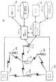
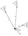
図1には本発明を実施するために適しているシステム100が示されている。このシステムはユーザによって操作されるデバイス102と、DTVトランスミッタ106A−106Nと、モニタステーション108A−108Nと、DTV位置サーバ110と、サービスプロバイダシステム120とを含んでいる。DTVトランスミッタ106は、デバイス102およびモニタステーション108へのものを含むDTV信号を放送する。DTV位置サーバ110はユーザデバイス102(この例においてはベースステーション(基地局)104を介して)およびモニタステーション108にリンクされている。サービスプロバイダシステム120はDTV位置サーバ110およびユーザデバイス102(この例においては再びベースステーション104を介して)にリンクされている。Overview FIG. 1 shows a
図2−図3は本発明に係る方法を示すフローチャートである。一般的に述べると、図2に示されているように、210においてデバイス102の位置がこのユーザデバイス102によって受信されたDTV信号を使用して判定される。この位置に基づいたサービスが220において提供される。 2 to 3 are flowcharts showing the method according to the present invention. Generally speaking, as shown in FIG. 2, at 210, the position of the
図1の例において、DTVトランスミッタ106、モニタステーション108、およびDTV位置サーバ110は、210のデバイス102の位置の判定に含まれている。この(図2にも示されている)実施形態において、デバイス102によって受信された放送DTV信号が212においてユーザデバイス102とDTVトランスミッタ106との間の擬似距離を計算するために使用される。この擬似距離は続いて214においてデバイス102の位置を判定するために使用される。図示されている実施形態において、擬似距離はDTVトランスミッタ106とユーザデバイス102の間の飛行時間(Time of Flight)に基づいており、受信されたDTV信号によって判定される。モニタステーション108は、各DTVトランスミッタ106のクロック間のクロックスキューを追跡する。サーバ110は、ユーザデバイス102からの飛行時間測定値とモニタステーション108からのクロックスキュー情報を用いてユーザデバイス102の位置を計算する。サーバ110はさらに気象条件に従った校正を行うためにウェザーサーバ104にアクセスし、DTVトランスミッタ106の既知の位置を得るためにDTV位相中心データベース112にアクセスする。さらに、多様な実施形態の詳細が図7ないし図34に示されている。 In the example of FIG. 1,
図1の例において、220においてサービスプロバイダシステム120がサービスを提供する。サービス自体はデバイスの位置に依存するものである。特定の適用形態において、220においてデバイス102のユーザに対してサービスが提供される。他の適用形態においては、第三者にサービスが提供される。図1に示された実施形態において、サービスプロバイダシステム120はDTV位置サーバに110にリンクされており、ここからサービスプロバイダシステム120がデバイスの位置にアクセスする。サービスプロバイダシステム120は、DTV位置サーバ110およびユーザデバイス102に対する場合と同様に、データベース122、サーバ124等にアクセスしてその機能を実行することができる。 In the example of FIG. 1, at 220, the
タスクの配分例
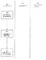
図1ならびにこれに従ったユーザデバイス102、DTV位置サーバ110およびサービスプロバイダシステム120の間の機能の配分は単に例示的なものであることが理解される。図3A−図3Cには別の配分例が示されている。これらのフローチャートにおいて、ユーザデバイス102、DTV位置サーバ110およびサービスプロバイダシステム120はそれぞれ1つの列で示されており、特定の列内の活動の位置は該当するデバイスがその活動を実行することを示している。Example Task Allocation It will be appreciated that the allocation of functionality between the
図3Aには前述した配分が示されている。この例において、212においてユーザデバイス102が擬似距離を計算し、これはその後213においてDTV位置サーバ110に伝送される。この擬似距離から、214においてDTV位置サーバ110がデバイス102の位置を判定し、215においてこの位置をサービスプロバイダシステム120に伝送する。220においてサービスプロバイダシステム120がサービスを提供する。この方式の1つの利点は、全ての実体が実行する機能によって専門化されている点である。例えば、デバイス102が移動体であるため計算能力またはデータ記録容量が限られている場合、複雑な計算または大量のデータはDTV位置サーバ110またはサービスプロバイダシステム120にシフトすることができる。さらに、異なった実体が異なった役目に使用されるため、図3Aの方式はモジュール性を提供するものである。例えば、サービスプロバイダシステム120は異なったタイプのサービスを提供するように変更することができるが、全て共通のDTV位置サーバ110の利点を取り入れるものとなる。一変更例において、同じ実体がDTV位置サーバおよびサービスプロバイダシステム120の機能を果たす。 FIG. 3A shows the distribution described above. In this example, at 212, the
異なった実体間のハンドオフはその情報に基づいている。例えば、212において擬似距離を計算するよりも、デバイス102は部分的に処理された相関等の他の中間的な計算値を伝送することができる。同様に、DTV位置サーバ110とサービスプロバイダシステム120との間のハンドオフは何か他の情報に基づくものとすることができる。これらのハンドオフはその他の中間ステージに基づいて実施することができるが、便宜上これらの2つのハンドオフは擬似距離およびデバイスの位置の伝達に関して常に論述される。 Handoffs between different entities are based on that information. For example, rather than calculating the pseudorange at 212,
図3Bにおいて、ユーザデバイス102はそれ自身の位置を計算する。言い換えると、デバイス102は212において受信したDTV信号から擬似距離を計算し、214においてこの擬似距離に基づいて自身の位置を判定する。デバイス102は215においてその位置をサービスプロバイダシステム120に伝達し、このサービスプロバイダシステムが220においてサービスを提供する。ここでは、独立した位置サーバ110は必要でない。従って、この方式の利点はより少ない実体を配置すれば良い点である。 In FIG. 3B, the
図3Cにおいて、ユーザデバイス102は全ての機能を実行する。デバイス102は212において受信したDTV信号から擬似距離を計算し、214において擬似距離に基づいてその位置を判定し、さらに220においてそれ自体に対してあるいはユーザに対してサービスを提供する。ここでは独立したDTV位置サーバ110およびサービスプロバイダシステム120は存在しない。この方式は自身で全てを含んでいる。これは外部の実体に依存せず、またそれに伴った通信リンクも必要としない。従ってこの方式の利点の1つは、独特の高い移動性である。 In FIG. 3C, the
図3Dは図3Cの変更例であり、これにおいて位置計算は外部のDTV位置サーバ110によって実行される。これによって、より強固および/または正確なデバイスの位置計算が可能になるが、依然として図3Cの方式の移動性を保持している。 FIG. 3D is a modification of FIG. 3C, in which the location calculation is performed by an external
有利な変更例をいくつか統合するために、デバイス102によってまたは外部のシステム(例えば前記のDTV位置サーバ110等)と組み合わせることによってデバイスの位置計算が完全に実施される。一度位置が判定されるとデバイス102、DTV位置サーバ110、または独立したサービスプロバイダシステム120によってサービス自体が提供される。最後の変更例として、デバイス102、そのユーザ、または第三者に対してサービスを提供することができる。その他の変更例も明らかにされる。どの実体がどの機能を実行するかの選択は提供されるサービスの性質に依存したものとなる。 In order to integrate some advantageous modifications, the location calculation of the device is completely performed by the
DTV位置確認の利点
種々の機能がどのように分配されるかにかかわらず、全ての方式がDTV信号に基づいてデバイス102の位置を判定する。この方式は多くの利点を有している。まず、DTV信号は優れた到達範囲を有している。米国においてはDTV信号の使用が連邦通信委員会によって推奨されている。2000年末現在166個以上のDTVトランスミッタが稼動しており、連邦通信委員会は2006年に全てのテレビ放送が新しくデジタルチャネルに割り当てられるという目標を挙げている。同様な放送範囲が欧州および日本でも期待されている。Benefits of DTV Localization Regardless of how the various functions are distributed, all schemes determine the location of
GPSに比べて、DTV信号は40dB超出力が大きい利点を有し、また衛星システムが提供し得るものよりも幾何学的配列の点で優れており、これによって通常GPS信号の受信が極めて困難になる障害物が存在する場合あるいは屋内においても位置確認が可能になる。DTV信号はGPSに比べて約6ないし8倍の帯域幅を有し、これによってマルチパス現象を最小限に抑えることができる。距離測定に使用されるDTV信号内の高出力および成分特性(例えばATSC−DTV信号の低いデューティファクタおよびETSI−DTV信号の分散した周波数)のため、処理要求は最小限のものとなる。本発明は、GPS技術が必要とするものに比べてはるかに低コスト、低処理速度および低出力のデバイスで実施することができる。加えて、DTVトランスミッタとユーザとの間の距離はGPSに比べて極めて緩慢に変化する。従ってDTV信号はドップラー効果によって大きな影響は受けない。このことによって信号を時間周期で積算することが可能になり、その結果極めて効果的な信号捕捉が得られる。 Compared to GPS, DTV signals have the advantage of greater than 40 dB power and are superior in geometrical arrangements than satellite systems can provide, which usually makes it very difficult to receive GPS signals. The position can be confirmed even when there is an obstacle or indoors. The DTV signal has about 6 to 8 times the bandwidth of the GPS, so that the multipath phenomenon can be minimized. Due to the high power and component characteristics within the DTV signal used for distance measurement (e.g., the low duty factor of the ATSC-DTV signal and the dispersed frequency of the ETSI-DTV signal), processing requirements are minimized. The present invention can be implemented with much lower cost, lower processing speed, and lower power devices than what GPS technology requires. In addition, the distance between the DTV transmitter and the user changes very slowly compared to GPS. Therefore, the DTV signal is not significantly affected by the Doppler effect. This allows the signals to be integrated over time, resulting in a very effective signal acquisition.
従来の携帯電話システムに比べてDTV信号の周波数は実質的に低いものとなり従ってより良好な伝搬特性を有する。例えば、DTV信号は携帯電話信号よりも大きな回折を有し、従って山の影響が少なくより大きな到達範囲を有する。さらに、この信号は建物および自動車を介する伝搬特性もより良好なものとなる。携帯電話の位置を確認するために使用する場合、地上波到着角度/到着時間位置確認システムと異なって、本発明の実施は携帯電話基地局のハードウェアの変更を必要とせず、また1mの単位の精度を実現することができる。この技術はエアインタフェースに依存しておらず、GSM(グローバルシステムモバイル)、AMPS(アドバンスドモバイルフォーンサービス)、TDMA(時分割多重アクセス)、CDMA(符号分割多重アクセス)等のいずれの方式でも可能である。広帯域のUHF(極超短波)周波数がDTVトランスミッタに割り当てられている。従って、システム内に構成されたリダンデンシーが存在し、これは吸収、マルチパス、およびその他の減衰要因による特定周波数のディープフェードを防止することができる。 Compared to conventional mobile telephone systems, the frequency of the DTV signal is substantially lower and therefore has better propagation characteristics. For example, DTV signals have greater diffraction than cell phone signals, and thus have less hill effects and greater range. In addition, this signal has better propagation characteristics through buildings and automobiles. Unlike the terrestrial arrival angle / arrival time location system, when used to determine the location of a mobile phone, the implementation of the present invention does not require any changes in the hardware of the mobile phone base station and is in units of 1 m. Accuracy can be realized. This technology does not depend on the air interface, and can be any of GSM (Global System Mobile), AMPS (Advanced Mobile Phone Service), TDMA (Time Division Multiple Access), and CDMA (Code Division Multiple Access). is there. Broadband UHF (Ultra High Frequency) frequencies have been assigned to DTV transmitters. Thus, there is redundancy configured in the system, which can prevent deep fades of certain frequencies due to absorption, multipath, and other attenuation factors.
図4ないし図6には種々のサービス例の実施形態が例示されている。これらの図において、簡略化のためシステムの位置確認部が省略されているが、一般的に前述したものと同様である。これらの図はシステムのサービスプロバイダ部分の多様な実施形態を示している。各実施形態は特定のサービスの内容で記述されているが、広範なサービスに適用可能である。例えば、図4A−図4Cはナビゲーションサービスの内容で記述されユーザデバイス102とサービスプロバイダシステム120の間でどのようにデータおよび機能を分配するかを示しているが、これらの図に示された種々のデータおよび機能配分は他のサービスにも同様に適用可能である。 4 to 6 illustrate various service example embodiments. In these figures, the position confirmation unit of the system is omitted for simplification, but is generally the same as that described above. These figures show various embodiments of the service provider portion of the system. Although each embodiment is described in the context of a particular service, it is applicable to a wide range of services. For example, while FIGS. 4A-4C illustrate how data and functions are distributed between the
ナビゲーションサービス
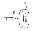
図4Aないし図4Cにはナビゲーションに関するサービスを提供する実施形態の例が示されている。このシステムは地図データベース422を備えている。図4Aにおいてサービスプロバイダシステム120は地図データベース422にアクセスし、重要な情報をユーザデバイス102に伝送してナビゲーションサービスを提供する。図4Bにおいて、サービスプロバイダシステム120はナビゲーションサービスの提供を補助するが、ユーザデバイス102は直接地図データベース422にアクセスする。図4Cにおいて、ユーザデバイス102はサービスプロバイダシステム120を使用せずにナビゲーションサービスを提供する。代替的な実施例において、地図データは2つのデータベース間に分割されており、1つはサービスプロバイダシステム120がアクセスし、もう1つはユーザデバイス102がアクセスするものである。Navigation Service FIGS. 4A to 4C show an example of an embodiment for providing a service related to navigation. This system has a
地図データベース422はナビゲーションサービスのための情報を提供するために使用される。1つの実施形態において、提供されるナビゲーション情報はデバイス102の周囲の地域地図である。デバイス102の位置が更新されるとこの地図も更新される。図4Aにおいて、サービスプロバイダシステム120は前述したように判定されたユーザデバイス102の位置にアクセスする。システム120はデバイス102の位置に基づいてデータベース422から重要な地図データを入手し、この地図データをディスプレイ装置に伝送する。代替的な実施例において、サービスプロバイダシステムが地図データを可視地図画像に加工しこの画像をデバイス102に伝送し、これが画像を受信して地図を表示する。
図4Bにおいて、サービスプロバイダシステム120はナビゲーションサービスを補助するが、地図データベース422にはデバイス102がアクセスする。例えば、サービスプロバイダシステム120はどの地図データが重要であるか(例えば米国地質調査グリッド第XXX番等)の確認を行うことができ、この地図データのキーコードをユーザデバイス102に伝送する。ユーザデバイス102はこのキーコードに基づいてデータベース422から地図データを取得する。代替的な実施例において、地図データベースはユーザデバイス102によってアクセスされるが第三者によって制御される。サービスプロバイダシステムはユーザデバイス102にキーコードを伝送し、これはこのデバイスがデータベースの重要な部分にアクセスすることを許可するものである。 In FIG. 4B, the
図4Cにおいてはサービスプロバイダシステム120が存在しない。ユーザデバイス102はその位置に基づいて重要な地図データを判定し、データベース422からこの重要な地図データを取得し、地図画像をディスプレイに提供する。例えば、この主のシステムはソフトウェアならびにCDあるいはDVDに記録された地図データベースと共に車両に搭載することができる。デバイス102の位置はユーザデバイス102自体および/または、前述したように、独立したDTV位置サーバ110によって判定することができる。 In FIG. 4C, the
別の実施形態において、ナビゲーション情報はデバイスの位置から別の関心のある地点へ、あるいは別の関心のある地点からデバイスの位置への道案内を含んでいる。ガス、食料、宿泊施設、医療、警察等が、ユーザが位置確認を希望する一般的な関心地点である。エンターテイメント、史跡、娯楽エリア、店舗、モール、および輸送センター等がさらに別の関心地点である。地図を提供する例と同様に、道案内の計算はユーザデバイス102、サービスプロバイダシステム120、これら2つの間によって実行することができる。例えば、ユーザが道案内を要求し、サービスプロバイダシステム120は要求に応答して道案内を計算しユーザに伝送する。 In another embodiment, the navigation information includes directions from the location of the device to another point of interest, or from another point of interest to the location of the device. Gas, food, accommodation, medical care, police, etc. are common points of interest that the user wants to locate. Entertainment, historic sites, entertainment areas, stores, malls, transport centers, and the like are yet other points of interest. As with the example of providing a map, the calculation of directions can be performed by the
ナビゲーションサービスは多様な内容をもって提供することができる。一例によれば、ユーザデバイス102は車両の付属品あるいは一部として統合することができ、ナビゲーションサービスは車両の誘導補助とすることができる。例には自動車およびその他の原動機付車両のための高速道路および一般道路の地図、オフロード車のための地形図またはトレールガイド、および飛行または船舶(DTV信号の範囲内に存在する場合)のためのナビゲーション補助が含まれている。別の例として、ユーザデバイス102は個人によって携帯され、この個人にパーソナルナビゲーション補助を提供する。例には、都市設定(例えば都市近郊での道順を検索する)および地方設定(例えばハイキング)、軍事応用(例えば戦場内の兵士用)、およびゲーム内容(例えばペイントボール、キャプチャー・ザ・フラッグ、または戦争ゲーム)に関するものが含まれている。DTVベースのナビゲーションサービスは、その他のタイプのナビゲーションサービス(例えばGPSベースのもの)に付加的に使用することもできる。 Navigation services can be provided with various contents. According to one example, the
追跡サービス
提供することができる別の一般的なクラスのサービスは追跡(トラッキング)サービスである。このサービスのクラスにおいてはデバイス102の位置が追跡される。デバイス102が高価である場合、デバイス102自体の追跡が価値のあるサービスとなる。しかしながら、デバイス102を対象物に取り付けることができ、その場合デバイス102の追跡は対象物の追跡と等しくなる。追跡することが有効である対象物の例は、自動車(乗用車および貨物車を含む)、航空機、貨物コンテナ、鉄道車両、資本設備、レンタル設備、および人物(例えばデバイスを携帯する子供)が含まれる。Tracking Services Another common class of services that can be provided is tracking services. In this class of service, the location of the
一実施形態において、デバイスはリアルタイムで追跡され追跡サービスは第三者に提供される。例えば、企業がその内部業務の1つとしてあるいは盗難および紛失を削減するため種々の対象物の追跡を希望することがあり得る。追跡情報は対象物の所有者、対象物の保険引受人または同様な理由の法的権利者に提供することができる。複数の対象物が追跡される場合、それらの対象物からの追跡情報は1つの場所(例えば中央データベース)に集積され、一般的な追跡ソフトウェアを使用して追跡データを効果的に分析および提示することができる。 In one embodiment, the device is tracked in real time and the tracking service is provided to a third party. For example, a company may wish to track various objects as one of its internal operations or to reduce theft and loss. The tracking information can be provided to the owner of the object, the underwriter of the object or a legal right holder for similar reasons. When multiple objects are tracked, the tracking information from those objects is collected in one location (eg, a central database) and the common tracking software is used to effectively analyze and present the tracking data. be able to.
別の例においては、現在のデバイスの位置を追跡するのではなく、デバイスの位置の経歴がその後の使用のために記録される。1つの例は“ブラックボックス”応用である。ブラックボックスが自給式である場合、デバイスは外部の実体(例えばDTV位置サーバ110およびサービスプロバイダシステム120)に頼らずに自身の位置を判定してその位置の経歴をデバイス内に記録する。 In another example, rather than tracking the current device location, a history of the device location is recorded for subsequent use. One example is a "black box" application. If the black box is self-contained, the device determines its location without relying on external entities (eg,
デバイス設定サービス
別の一般的なクラスのサービスにおいて、デバイス102の設定が位置に基づいて調節される。1つの例は携帯電話サービスである。この例において、デバイス102は携帯電話であるがDTV位置確認回路を備えている。このDTV位置確認回路(DTV位置サーバ110の補助も可能である)は携帯電話の位置を判定する。その後携帯電話の位置を考慮しながらこの携帯電話に対して調節が行われる。Device Configuration Service In another common class of services, the configuration of
最適なデータ速度、符号化/変調、アンテナ構成、またはその他携帯電話の受信パラメータが位置によって変化する。一度携帯電話の位置が判定されると、これらのパラメータのいずれかが位置を考慮して調節される。その位置が多数の携帯電話通話、強いマルチパス成分、強力な障害を通信経路内に有している場合、より強力な通信チャネル(例えばより低いデータ速度およびより強力なエラー復号)が必要とされ、これによってユーザデバイス102への伝送品質が改善される。所与の位置に対するマルチパス特性が既知である場合、このマルチパスを考慮に入れて受信した携帯電話信号を処理するためのフィルタ係数およびアンテナ構成を変更することができる。 Optimal data rates, coding / modulation, antenna configuration, or other mobile phone reception parameters vary with location. Once the location of the mobile phone has been determined, any of these parameters are adjusted to account for the location. If the location has multiple mobile phone calls, strong multipath components, strong obstacles in the communication path, stronger communication channels (eg, lower data rates and stronger error decoding) are needed. , Thereby improving the quality of the transmission to the
図5には地理的領域に基づいた調節の例が示されている。より具体的には、地理的範囲が異なった領域510に分割され、携帯電話に対する調節はそれが存在している地理的領域に基づいたものとなる。図5においては、サービスプロバイダシステム120がデバイスの位置を領域データベース522内に記録された領域と比較することによって重要な領域を判定する。領域510は特定の領域510が特定の位置を含むように効果的に決定することを可能にする方式で定義することが好適である。例えば、例えば、領域はその境界の地理座標によって定義することができる。図5に示されている領域は全て等しい大きさおよび形状を有しているが、これは必ずしも必要でない。領域は異なった形状および大きさを有することができる。領域の境界および境界の数は時間とともに変化することができる。 FIG. 5 shows an example of adjustment based on geographical area. More specifically, the geographic area is divided into different regions 510, and adjustments to the mobile phone are based on the geographic region in which it resides. In FIG. 5, the
一構成形態において、領域510は到達範囲内のセルに相当する。各セルは異なった基地局によって提供される。従って、どのセル内にデバイス102が存在するかを知ることによって特定の基地局に対してデバイス102の最適化を可能にする。例えば、デバイス102が1つのセルから別のセルに横断する場合、そのアンテナは新しいセルの基地局に指向すべきである。別の例として、各基地局が異なった符号化または変調技術を使用する場合、デバイス102はそれらの利点を取り入れるように設定することができる。最後の例として、各セルは異なったタイプあるいは異なった品質のサービスを提供することができる(例えば、市内、地域、あるいは長距離等)。従って、ユーザデバイス102を設定するためにそれがどのセル内に存在するかを知ることによって、異なったサービスまたはサービスの品質の利点を考慮する。 In one configuration, region 510 corresponds to a cell within range. Each cell is provided by a different base station. Thus, knowing in which cell the
領域510はセルに一致する必要はない。例えば、マルチパス現象を補償するケースにおいて、各領域510は特定のマルチパス特性を有する地理的範囲を示すことができる。領域510Aは近くの高いビルディングの反射によって支配されとする。領域510Bは複数の面の反射によって特徴付けるものとする。領域510Cは比較的弱いマルチパスによって特徴付けるものとする。携帯電話は、その領域の特徴であるマルチパス現象を補償するよう設定される。 Region 510 need not correspond to a cell. For example, in the case of compensating for multipath phenomena, each region 510 may represent a geographic area having particular multipath characteristics.
このデバイス102の設定の調節方式は携帯電話に限定されるものではない。インターネットアクセスまたはその他のワイヤレス通信チャネル(例えばワイヤレスモデム)を提供するデバイスもこの方式によって有利となる。加えて、デバイス102は移動体である必要もない。1つの例によれば、デバイス102は、自身の位置を判定して地域の放送チャネルを最適に受信するよう自身で設定するテレビジョンとすることができる。 The method of adjusting the settings of the
この調節は、特定の適用形態の要件に応じて、全てデバイス102によって(例えば図4Cに示されているように)、全て独立したサービスプロバイダによって(例えば図4Aに示されているように)、あるいはそれら2つの間で判定することもできる。特定の適用形態において、デバイスのユーザからの明確な要求を伴わずに調節が自動的に実施される(例えば携帯電話の受信を改善するためあるいはテレビジョンの自動設定のため)。他の適用形態においてはユーザが調節を開始する必要がある(例えばテレビジョンの自動設定を実行するためにボタンを押すことによって)。 This adjustment may be performed by the device 102 (eg, as shown in FIG. 4C), by all independent service providers (eg, as shown in FIG. 4A), depending on the requirements of the particular application. Alternatively, the determination can be made between the two. In certain applications, the adjustment is performed automatically without explicit request from the user of the device (for example, to improve the reception of the mobile phone or for the automatic setting of the television). In other applications, the user needs to initiate the adjustment (eg, by pressing a button to perform an automatic configuration of the television).
物理的サービス
デバイス102の位置を知ることによって物理的サービスも可能になるあるいは拡大することができる。1つの例として、デバイスの位置を知ることによって物理的サービスをその特定位置に搬送することが可能になる。緊急ロードサイド支援、救急911サービス、および食品の配達がこの種のサービスの例である。救急911の例において、救急911を要求しているデバイス102の位置がDTV信号に基づいて判定される。その後適宜な救急911ユニットがデバイスの位置に急送される。Physical Services Knowing the location of the
前述したサービスのクラスと同様に、物理的サービスも複数の方式で提供することができる。1つの方式において、サービスプロバイダシステム120が物理的サービスの要求を受信すると、サービスプロバイダ自体がデバイスの位置に移動してその物理的サービスを実行する。別の方式においては、サービスプロバイダ自体は物理的サービスを実行しない。それに代えて、サービスを提供する地域サービスプロバイダに連絡する。例えば、図5を参照すると各領域510に対してサービスを行う地域サービスプロバイダが存在することができる。一度サービスプロバイダシステム120がどの領域にデバイスが位置しているかを判定すると、適宜な地域サービスプロバイダに連絡してサービスを提供する。緊急ロードサイド支援に関して、サービスプロバイダは中央自動車クラブとすることができ、これは地域レッカー業者のネットワークを利用してロードサイド支援を提供する。別の代替例において、サービスプロバイダシステム120は物理的サービスの提供を許可するキーコードをデバイスへ伝送する。例えば、ユーザはそのキーコードを地域レッカー業者に提示して彼の車を牽引させることができる。 As with the classes of services described above, physical services can be provided in multiple ways. In one scheme, when the
最後の例として、サービスの品質が領域ごとに異なることができる。例えば、サービスが食事の配達である場合、都会の領域においては地方の領域よりも速い配達を保証することができる。 As a last example, the quality of service can vary from region to region. For example, if the service is meal delivery, faster delivery can be guaranteed in urban areas than in rural areas.
地域限定情報サービス
別のクラスのサービスにおいては、デバイス102のユーザに情報が提供され、その情報はデバイスの位置に従って地域限定されたものとなる。その例には、地域ニュース、地域交通情報、ならびにデバイスの周辺の地域の商業施設または関心のある地点に関する情報(説明、営業時間、広告、紹介、クーポン等)を含んでいる。Localized Information Services In another class of services, information is provided to the user of the
図4Aの構造において、サービスプロバイダシステム120が地域限定された情報を決定し、例えばそれを中央データベースから抽出する。この情報はデバイス102に伝送され、これがその情報をユーザに対して表示する。例えば、地域ニュースの場合、中央データベースは多数の地方自治体からのニュースを含むことができる。サービスプロバイダシステム120はどの自治体地域にデバイスが位置しているかを判定し、その自治体の地域ニュースをデバイスに伝送する。これに代えて、サービスプロバイダシステム120はデバイス102に対してキーコードを送信することができる。このキーコードはデバイスが異なったソース、例えばニュースデータベースを保持する第三者から地域ニュースを入手することを可能にする。この例において、ニュースは自治体に基づいて地域限定され、これは図5に示されている領域ベースモデルに従ったものとなる。各自治体は独立した領域510でありユーザに提供される地域ニュースはユーザがどの自治体地域に位置しているかに基づいたものとなる。 In the structure of FIG. 4A, the
別の例は仮想ツアーガイドである。この適用形態においては、関心地点のツアーがデバイス102を通じて提供される。例えばユーザが動物園を訪問する場合、ユーザが例えばペンギンのスペースの近くに居る場合ペンギンのスペースの説明が提示される。ユーザが歴史的戦場を訪問する場合、デバイスはこのデバイスが位置する地域で発生した出来事の説明を提示することができる。デバイスが移動すると、新しい位置を説明するように情報が変更される。関連するサービスにおいて、ユーザは関心地点の“電子ポストカード”を受け取り、これは彼が購入することができるものである。デバイスはその時点の位置に基づいてポストカードを提示する。例えば、デバイスがフーバーダムの周辺に位置している場合、これはディズニーランドではなくフーバーダムの画像を提示する。 Another example is a virtual tour guide. In this application, a tour of the point of interest is provided through
別の例において、デバイス102は安全および救助情報を提供するために使用される。デバイスの位置において影響がある緊急事態が発生した際、この緊急事態に関する情報がユーザに提供される。例えば、地震が発生しデバイスがその地震の地域に存在している場合、地震の詳細および救援情報、またはどのようにこの地震に対処するかの指示が提供される。 In another example,
特定の適用形態において、ユーザは地域限定された情報を要求する。例えば、ユーザは新聞を購読する場合と同様に地域ニュースを要求して支払うことができる。別の適用形態において、地域限定された情報は非請求のメッセージである。例えば、ユーザが店舗の前を通過して歩く場合、デバイスはその店舗のクーポンを提供することができる。緊急事態の発生に際して、ユーザは自動的に安全処置および救助活動に対する情報を受け取ることができる。1つの実施形態において、ユーザは非請求情報に関する種々の選択肢の中から選択を行うことができる。考えられる1つの選択肢はユーザデバイス102が継続的に追跡され継続的に非請求情報を受信することである。別の選択肢は全ての非請求情報を拒否することである。第3の選択肢はユーザが要求した場合にのみ情報を受信することである。 In certain applications, the user requests localized information. For example, a user can request and pay for local news as if subscribing to a newspaper. In another application, the localized information is an unsolicited message. For example, if a user walks past a store, the device may provide a coupon for that store. In the event of an emergency, the user can automatically receive information on safeguards and rescue operations. In one embodiment, the user can make a selection from a variety of options for unsolicited information. One possible option is that the
ユーザは予め登録したプロフィールに基づいて情報を受信することもできる。例えば、ユーザはアイスクリームを好みクッキーを好まないことを示すことができる。ユーザが街中を歩いた場合、彼は地域のアイスクリーム店の情報を受け取るがクッキー販売店の情報は受け取らない。 The user can also receive information based on a profile registered in advance. For example, a user may indicate that they like ice cream and do not like cookies. If the user walks around the city, he will receive information about the local ice cream store but not the cookie store.
多くのサービスのクラスと同様に、地域限定された情報の提供は固定の装置にも適用される。1つの適用形態において、デバイス102はテレビジョン装置に組み込まれ、これが自身の位置を判定することができる。このテレビジョン装置に対するテレビ放送は様々な広告の選択性を含んでいる。テレビジョン装置はその位置に対応した広告を選択する。 As with many service classes, the provision of localized information also applies to fixed devices. In one application,
追加的なサービスの例
図6には提供されるサービスがビデオゲームであるシステムが示されている。この例において、適宜なワイヤレスゲーム装置102Aおよび102Bを有する2人のユーザが互いに共同に/あるいは対戦してビデオゲームをプレイしている。ビデオゲームはワイヤレスゲーム装置と結合された例えば携帯電話、PDAまたはその他の表示装置に局所的に表示される。ビデオゲーム内におけるユーザの移動は実世界における彼らの位置に基づいたものとなる。サービスプロバイダシステム120はDTV信号によって判定されたワイヤレスゲーム装置の位置に従ってユーザの位置を決定し、これに従ってビデオゲームを更新する。この方式によって1人用あるいは2人より多くのプレーヤーのためのビデオゲームも実施することができる。Example of Additional Services FIG. 6 shows a system in which the service provided is a video game. In this example, two users with appropriate
別の適用形態において、デバイス102の位置は測量の補助とすることができる。例えば、測量人がある場所においてデバイス102を携帯し、その場所の各地点において位置を記録することができる。 In another application, the location of the
最後の例において、デバイス102は特定の別の個体が接近してきた場合にユーザに警告を提供するために使用することができる。例えば、ユーザは市民戦争の記録に興味がある別の個人とミーティングを行うことに興味があることを彼のプロフィールに示すことができる。ユーザのプロフィールはサービスプロバイダシステム120に記録される。ユーザが街中を歩き回った際に、サービスプロバイダシステム120はデバイスの位置を追跡し、同様に他のユーザのデバイスの位置を追跡する。別のユーザが近くにいて同様に市民戦争の記録に興味を示している場合、サービスプロバイダシステム120がユーザに警告を発し、その結果彼らは希望によって互いに会談することができる。デーティングおよび結婚仲介等を含む他の要件を使用することもできる。 In the last example, the
前述した実施形態およびサービスは単に例示的なものであることが理解される。全てのタイプのサービスまたはサービスを提供するためのシステムをリストアップすることは現実的でない。例えば、ユーザはシステムの残りの部分に任意の数のデバイス102を介してアクセスすることができる。例には、携帯型コンピュータ、PDA、携帯電話、自動車およびその他の車両、ならびにDTV位置確認を実行するチップまたはソフトウェアを備えることができるいずれかの対象物が含まれる。ユーザインタフェースの例には、一般的なモニタおよびキーボード、タッチスクリーンディスプレイ、ならびに音声認識および合成装置等が含まれる。ユーザデバイス102は広域性の手段によって実施することができる。例えば、アンテナ、ユーザインタフェース、マイクロプロセッサ、電源、および局部記録装置は、ケーブル、近距離無線(例えばブルートゥース)、赤外線その他の手段等の通信手段を伴って異なった場所に位置することができる。 It is understood that the above-described embodiments and services are merely exemplary. It is not practical to list all types of services or systems for providing services. For example, a user can access the rest of the system via any number of
同様に、DTV位置サーバ110およびサービスプロバイダシステム120は多数の異なった装置を使用してその機能を実行することができる。一実施形態において、DTV位置サーバ110は前述された動作を実施するように設計されたソフトウェアを実行する汎用コンピュータ(一群のコンピュータ)として実施することができる。別の実施形態において、DTV位置サーバはASIC(特定用途向け集積回路)として実施することができる。サービスプロバイダシステム120も同様に実施することができる。 Similarly,
ユーザデバイス102、DTV位置サーバ110およびサービスプロバイダ120の選択は、提供されるサービスの性質に基づくものとなる。これはさらにユーザデバイス102、DTV位置サーバ110およびサービスプロバイダシステム120の間の通信リンクの性質に基づいたものとなる。 The choice of
通信リンクは多くの異なった形式とすることができる。図1において、デバイス102とDTV位置サーバ110との間のリンクは、ベースステーション104への無線リンクおよびベースステーション104からDTV位置サーバ110へのより恒久的なリンク(例えば地上線)とすることができる。1つの例において、ユーザデバイス102はコードレス電話であり、ベースステーション104はコードレス電話ベースステーションとすることができる。1つの実施形態において、ベースステーション104は移動MAN(メトロポリタンエリアネットワーク)またはWAN(ワイドエリアネットワーク)とすることができる。ユーザデバイス102とサービスプロバイダシステム120との間のリンクも同様に示されている。移動端末に適している衛星通信(例えばLEO,MEO,GEO等)も代替的なものとして考えられる。非移動端末(図1の実施形態におけるDTV位置サーバ110とサービスプロバイダシステム120との間)に適したものとして、地上線(例えば光ファイバ、ケーブル、電線等)およびマイクロ波リンクが代替のものとして挙げられる。これらの多様な通信リンクは適用形態に応じて一方向あるいは双方向性とすることができる。 The communication link can take many different forms. In FIG. 1, the link between
別の例として、サービスを実施するために要求される動作は、ユーザデバイス102、DTV位置サーバ110、ならびにサービスプロバイダシステム120の間で多様な方式で配分することができる。同様に、サービスプロバイダシステム120の役目もマイナーなものからメジャーなものに変更することができる。DTV位置サーバ110とサービスプロバイダ120との間で多様な方式で動作を配分することもできる。例えば、サービスプロバイダシステム120は、図1に示されているように直接でなく、DTV位置サーバ110を介してユーザデバイス102と交信することができる。その逆も勿論可能である。実際、ユーザデバイス102、DTV位置サーバ110、およびサービスプロバイダシステム120は図1において分離して示されているが、これは必ずしも必要であることはない。 As another example, the actions required to perform a service may be distributed among the
サービスを要求する方法およびサービスを配送する方法も変更することができる。例えば、ユーザはサービスが提供される前に明確に要求することができる。他方、暗黙、自動的、あるいはユーザ以外によって要求することができる。必ず要求され得るわけではない。これに代えて、サービスプロバイダがユーザに対してサービスを“プッシュ”することができる。配送に関して、サービスプロバイダシステム120はサービスの提供を許可するが、実際にサービスの提供を行うことができるか、あるいはできないようにすることができる。サービスプロバイダシステム120がサービスを提供しない場合、第三者がサービスを提供することをアレンジするか、あるいは適宜な箇所に要求を転送することができる。他方、サービスプロバイダシステム120はユーザに対して許可コードを送信し、ユーザがサービスを受けることを可能にすることができる。 The manner in which services are requested and the manner in which services are delivered can also vary. For example, a user can explicitly request before a service is provided. On the other hand, it can be requested implicitly, automatically, or by someone other than the user. It cannot always be required. Alternatively, the service provider can "push" the service to the user. With respect to delivery, the
最後の例に示されているように、提供され得るサービスは前述したものに限定されることはない。別のサービスは物品またはサービスの購入であり、これには映画チケット、レストランの予約、消費財、ガイドツアー、および地域ツアーブックが含まれる。追加的なサービスは地域商業施設の情報配信(例えば劇場の開演時間、レストランのメニュー等)または地域ニュース、交通および天気情報等の地域限定された情報である。表1には、特定のタイプの情報に対して薦められる現状の技術および品質基準を使用した大まかなデータ速度が示されている。データ速度は表に示されたものに限定されることはない。表において、データ付音声はテキスト情報またはテキストメッセージを伴った音声交信を含んだ情報流を示している。これは音声認識アプリケーションおよび標準の音声アプリケーションを伴ったテキストメッセージを含んでいる。 As shown in the last example, the services that can be provided are not limited to those described above. Another service is the purchase of goods or services, including movie tickets, restaurant reservations, consumer goods, guided tours, and regional tour books. Additional services are information distribution of local commercial establishments (eg, theater opening times, restaurant menus, etc.) or region-specific information such as local news, traffic and weather information. Table 1 shows approximate data rates using current state of the art and quality standards recommended for particular types of information. The data rates are not limited to those shown in the table. In the table, the voice with data indicates an information stream including voice communication accompanied by text information or a text message. This includes text messages with voice recognition applications and standard voice applications.

一般的な位置確認
図7にはユーザの位置を判定する方法が示されている。ユーザデバイス102は複数のDTVトランスミッタ106Aおよび106Bないし106Nを介してDTV信号を受信する(ステップ702)。General Position Confirmation FIG. 7 shows a method for determining the position of the user.
どのDTVチャネルを位置確認に使用するか選択するために多様な方法が使用し得る。一実施形態において、DTV位置サーバ110がモニタするための最適なDTVチャネルをユーザデバイス102に伝達する。一実施形態において、ユーザデバイス102はベースステーション104を介してDTV位置サーバ110とメッセージの交換を行う。位置実施形態において、ユーザデバイス102はベースステーション104のアイデンティティとベースステーションとDTVチャネルを相関させる記録された表に基づいてモニタするDTVチャネルを選択する。別の実施形態において、ユーザデバイス102はユーザが入力した例えば一番近い都市名等の概略的な地域表示を示す位置を受領することができ;この情報を処理するDTV信号の選択に使用する。一実施形態において、ユーザデバイス102は受信可能なDTV信号をスキャンしてこの受信可能なDTVチャネルの出力レベルに基づいて位置の指紋を構成する。ユーザデバイス102はこの指紋を既知の位置を伴った既知の指紋に相当する記録された表と比較して処理するためのDTVチャネルを選択する。 Various methods may be used to select which DTV channel to use for localization. In one embodiment, the
ユーザデバイス102はユーザデバイス102と各DTVトランスミッタ10との間の擬似距離を判定する(ステップ704)。各擬似距離は、DTV放送信号の一成分のトランスミッタ108からの伝送時間とこの成分のユーザデバイス102おける受信時間との間の時間差、ならびにユーザデバイスにおけるクロックオフセットを示すものである。 The
ユーザデバイス102はこの擬似距離をDTV位置サーバ110に伝送する。一実施形態において、DTV位置サーバはベースステーション104内あるいはその近くに配置される。 The
DTV信号はさらに複数のモニタユニット108Aないし108Nによって受信される。各モニタユニットはトランシーバおよびプロセッサを含んだ小さなユニットとして実施され、電柱、DTVトランスミッタ106、またはベースステーション104等の適切な場所に設置することができる。一実施形態においてモニタユニットは衛星上に設置される。 The DTV signal is further received by a plurality of monitor units 108A-108N. Each monitor unit is implemented as a small unit containing a transceiver and a processor and can be located at any suitable location, such as a utility pole,
各モニタユニット108は、そこからのDTV信号を受信する各DTVトランスミッタ106に対してそのDTVのローカルクロックと基準クロックとの間のタイムオフセットを計測する。一実施形態において、基準クロックはGPS信号から抽出される。基準クロックの使用によって、各モニタユニット108が基準クロックに相対してタイムオフセットを決定し得るため、複数のモニタユニット108が使用される際に各DTVトランスミッタ106に対するタイムオフセットを判定することが可能になる。従って、モニタユニット108のローカルクロック内におけるオフセットはこの決定に影響を与えない。 Each monitor unit 108 measures the time offset between the local clock of the DTV and the reference clock for each
別の実施形態においては外部時間基準が必要とされない。この実施形態によれば、単一のモニタユニットが、ユーザデバイス102が行っているように同一のDTVトランスミッタからの全てのDTV信号を受信する。実際には、単一のモニタユニットのローカルクロックが時間基準として機能する。 In another embodiment, no external time reference is required. According to this embodiment, a single monitor unit receives all DTV signals from the same DTV transmitter as the
一実施形態において、各タイムオフセットは固定のオフセットとして形成される。別の実施形態において、各タイムオフセットはa,b,cおよびTによって示される以下の二次の多項式として形成される。 In one embodiment, each time offset is formed as a fixed offset. In another embodiment, each time offset is formed as the following quadratic polynomial, denoted by a, b, c, and T:
DTVロケーションサーバ110は、各DTVトランスミッタ106の位相中心(すなわち位置)を説明する情報をデータベース112から受領する。位置実施形態において、DTVトランスミッタ106の位相中心は異なった位置においてモニタユニット108を使用して計測され、位相中心が直接的に計測される。別の実施形態において、各DTVトランスミッタ106の位相中心はアンテナ位相中心を監視することによって計測される。
位置実施形態において、DTV位置サーバ110は、ユーザデバイス102の周辺の気温、気圧、湿度を示す気象情報を気象サーバ114から受信する。この気象情報はインターネットおよびNOAA等の他のソースから入手することができる。DTV位置サーバ110は、例えばB.パーキンソン氏およびJ.スピルカー・ジュニア氏等による1996年のワシントンDCにおけるAIAA第1巻“グローバルポジショニングシステム−セオリーおよびアプリケーション”、J.スピルカー・ジュニア氏による第17章“GPSにおける対流圏現象の影響”(これはここにおいて参照に組み入れてある)の技術を使用して気象情報から対流圏伝搬速度を判定する。 In the location embodiment, the
DTV位置サーバ110は、さらにユーザデバイス102の一般的な地理情報を示す情報をベースステーション104から受信する。例えば、この情報は携帯電話が位置しているセルまたはセル区部を示すことができる。以下に記述するように曖昧性解消のために使用される。
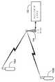
DTV位置サーバ110は、擬似距離および各トランスミッタの位置に基づいてユーザデバイス102の位置を判定する(ステップ706)。図8には3つのDTVトランスミッタ106を使用する位置判定の幾何学配置が示されている。DTVトランスミッタ106Aは位置(x1,y1)に存在している。ユーザデバイス102とDTVトランスミッタ106Aとの間の距離はr1とする。DTVトランスミッタ106Bは位置(x2,y2)に位置している。ユーザデバイス102とDTVトランスミッタ106Bとの間の距離はr2とする。DTVトランスミッタ106Nは位置(x3,y3)に存在している。ユーザデバイス102とDTVトランスミッタ106Nとの間の距離はr3とする。
DTV位置サーバ110は対流圏伝搬速度および対応するDTVトランスミッタ106のタイムオフセットに従って擬似距離の数値を調整することができる。DTV位置サーバ110はデータベース112からの位相中心情報を使用してDTVトランスミッタ106の位置を判定する。 The
ユーザデバイス102は、3つの未知数すなわち位置(x,y)およびユーザデバイス102のクロックオフセットTを解くために3つあるいはそれより多い擬似距離計測値を使用する。別の実施形態において、ここに開示されている技術は三次元すなわち緯度、経度、および標高において位置を判定するために使用され、DTVトランスミッタの標高等の要素を含むことができる。 The
3つの擬似距離計測値pr1,pr2,およびpr3は以下の式によって与えられる。 The three pseudo distance measurements pr1, pr2, and pr3 are given by the following equations.
別の実施形態において、ユーザデバイス102は擬似距離を計算せず、むしろ擬似距離を計算するために充分であるDTV信号の測定値を取り込み、この測定値をDTV位置サーバ110に伝送する。DTV位置サーバ110はこの測定値に基づいて擬似距離を計算し、前述したようにこの擬似距離に基づいてユーザの位置を計算する。 In another embodiment, the
別の実施形態において、デバイス102の位置はユーザデバイス102によって計算される。この実施形態においては、全ての必要な情報がユーザデバイス102に送信される。この情報はDTV位置サーバ110、ベースステーション104、1つまたは複数のDTVトランスミッタ106、またはそれらいずれかの組合せを介してユーザデバイスに伝送することができる。ユーザデバイス102はその後擬似距離を計測し、前述した連立方程式を解く。この実施形態についてさらに説明する。 In another embodiment, the location of
ユーザデバイス102は各DTVトランスミッタのローカルクロックと基準クロックとの間のタイムオフセットを受信する。ユーザデバイス102はさらに各DTVトランスミッタ106の位相中心を示す情報をデータベース112から伝送する。
ユーザデバイス102はDTV位置サーバ110によって計算された対流圏伝搬速度を受信する。別の実施形態において、ユーザデバイス102はこのユーザデバイス102の周囲の気温、気圧、および湿度を示す気象情報を気象サーバ114から受信し、一般的な手法を使用してこの気象情報から対流圏伝搬速度を判定する。
ユーザデバイス102はさらにベースステーション104からこのユーザデバイス102の大まかな位置を示す情報を受信する。例えば、この情報は携帯電話が位置しているセルまたはセル区部を示すことができる。この情報は以下に説明するように曖昧性解消に使用することができる。
ユーザデバイス102は複数のDTVトランスミッタ106からDTV信号を受信し、ユーザデバイス102と各トランスミッタ106との間の擬似距離を判定する。ユーザデバイス102はその後擬似距離およびトランスミッタの位相中心に基づいて位置を判定する。 The
これらの実施形態のいずれにおいても、2つのDTVトランスミッタのみが使用可能であればよく、ユーザデバイス102の位置はこれら2つのDTVトランスミッタならびに先行した位置判定中に計算されたオフセットTを使用して判定される。Tの値は一般的な手法に従って記録あるいは保持することができる。 In any of these embodiments, only two DTV transmitters need be available, and the position of the
一実施形態においては、ベースステーション104がユーザデバイス102のクロックオフセットを判定する。この実施形態においては、2つのDTVトランスミッタのみが位置判定のために必要とされる。ベースステーション104はDTV位置サーバ110にクロックオフセットTを伝送し、これは各DTVトランスミッタに対して計算された擬似距離からユーザデバイス102の位置を判定する。 In one embodiment,
別の実施形態において1つあるいは2つのDTVトランスミッタのみが、位置判定のために使用可能である場合、位置判定を増強するためにGPSが使用される。 In another embodiment, if only one or two DTV transmitters are available for position determination, GPS is used to enhance position determination.
図9には、2つの別々のDTVアンテナ106Aおよび106BからDTV信号を受信するユーザデバイス102の位置確認計算の簡単な例が示されている。各伝送アンテナ106Aおよび106Bに関する一定の距離の円902A902Bがそれぞれ図示されている。ユーザデバイスクロックオフセット校正を含むユーザデバイスの位置が2つの円902Aおよび902Bの交差点904Aおよび904Bのうちのいずれか1つの上に存在する。ベースステーション104がそのフットプリント(その到達範囲)906のうちのどの区部908にユーザデバイスが位置するかを判定し得ることを知ることによって曖昧性を解消することができる。勿論、2つよりも多いDTVトランスミッタが存在する場合、曖昧性は3つの円の交差部分から解消することができる。 FIG. 9 shows a simple example of a location calculation of a
一実施形態において、ユーザデバイス102は、最も近い都市の名前等概略的に地域を示したユーザからの入力を受領することができる。一実施形態においてユーザデバイス102は位置の指紋を形成するために使用可能なDTVチャネルをスキャンする。ユーザデバイス102は、この指紋を既知の位置の既知の指紋に符合する記録された表と比較しその時点のユーザデバイス102の位置を確認する。 In one embodiment, the
一実施形態において、位置計算は地形の隆起の影響を含んでいる。従って、丘陵および谷を含んだ地形においては、DTVアンテナ106の位相中心に関して等距離の円が変形させられる。図10には、周囲の土地と同じ標高に位置するDTVトランスミッタ106の等距離円1002に対する単一の丘1004の影響が示されている。 In one embodiment, the position calculation includes the effects of terrain bumps. Therefore, on a terrain including hills and valleys, a circle equidistant with respect to the phase center of the
ユーザ位置の計算は、データベースとして地域地形図を有する単純なコンピュータを使用して容易に計算することができ、これは地表面、ジオイドにおけるユーザの標高の影響を計算に含めることを可能にする。この計算は、図10に示されているように、等距離円の歪作用を有している。 The calculation of the user position can be easily calculated using a simple computer with a regional topographic map as a database, which allows the effect of the user's elevation on the ground surface, geoid, to be included in the calculation. This calculation has an equidistant circle distortion effect as shown in FIG.
ATSC位置確認
図11ないし図23には米国テレビジョン規格委員会(ATSC)DTV信号を使用する種々のレシーバが示されている。DTVは1998年に最初に米国で実用化された。2000年の末には、DTV信号を放送する167局が稼動していた。2001年2月28日現在で、1200のDTV設置許可がFCCによって発効されている。FCCの目標によれば、全てのテレビジョン伝送が早急にデジタルとなりアナログ信号が廃止されるべきであるとされている。公共放送局はその免許を保持するために2002年5月1日までにデジタル化しなければならない。民間ステーションは2003年5月1日までにデジタル化しなければならない。米国内に1600超のDTVトランスミッタの設置が期待されている。ATSC Localization FIGS. 11-23 show various receivers that use the American Television Standards Committee (ATSC) DTV signal. DTV was first commercialized in the United States in 1998. By the end of 2000, 167 stations were broadcasting DTV signals. As of February 28, 2001, 1200 DTV installation permits have been issued by the FCC. According to the FCC's goal, all television transmissions should be digital as soon as possible and analog signals should be abolished. Public broadcasters must digitize by May 1, 2002 to retain their license. Private stations must be digitized by May 1, 2003. Over 1600 DTV transmitters are expected to be installed in the United States.
新しいDTV信号は、割り当てられた6MHzチャネルで伝送されるマルチプルスタンダードデフィニションTV信号または高精細度信号を送信することを可能にする。これらの新しいアメリカテレビ規格委員会(ATSC)DTV信号はアナログNTSC−TV信号と全く異なっており、新しい6MHz周波数チャネルにおいて伝送され、全く新しい能力を備えている。 The new DTV signal allows for transmitting multiple standard definition TV signals or high definition signals transmitted on the assigned 6 MHz channel. These new American Television Standards Committee (ATSC) DTV signals are quite different from analog NTSC-TV signals, are transmitted on new 6 MHz frequency channels, and have entirely new capabilities.
発明者等はATSC信号が位置確認に使用できることを認識し、それを実行するための技術を開発した。この技術はATSC−DTVトランスミッタの周囲で使用することができ、その際のトランスミッタからの距離範囲は典型的なDTV受信範囲よりも遥かに広いものとなる。DTV信号の高い出力のため、この技術は屋内においても手持ち受信機によって使用することができる。 The inventors have recognized that ATSC signals can be used for position location, and have developed techniques for doing so. This technique can be used around ATSC-DTV transmitters, where the range from the transmitter is much larger than a typical DTV reception range. Due to the high power of the DTV signal, this technique can be used indoors with a hand-held receiver.
GPSのデジタル擬似ノイズコードとは対照的に、DTV信号はわずか数マイルの距離のトランスミッタから受信され、トランスミッタはメガワットレベルのまでの信号を発信する。加えて、DTVアンテナは14dBの単位の大きなアンテナゲインを有する。従って、DTV信号は屋内で受信するために充分な出力を有している。 In contrast to GPS digital pseudo-noise codes, DTV signals are received from transmitters that are only a few miles away, and the transmitters emit signals up to the megawatt level. In addition, DTV antennas have large antenna gains on the order of 14 dB. Thus, the DTV signal has sufficient power to receive indoors.
特定のレシーバ構成はDTV8−aryベスティジアルサイドバンド変調(8VSB)のデータ信号の復調および復号とは対照的にDTV信号同期コードのみを使用する。従って、DTV信号は、単一データシンボルの周期の約100万倍の周期で相関する。従って、DTVタワーから相当な距離において屋内で信号を追跡する可能性が大幅に拡大する。さらに、デジタル信号処理の使用を通じて、これらの新しい追跡技術を単一の半導体チップ内で実施することが可能となっている。 Certain receiver configurations use only DTV signal synchronization codes as opposed to demodulation and decoding of DTV 8-ary Vestigial Sideband Modulation (8VSB) data signals. Therefore, the DTV signal correlates with a cycle of about one million times the cycle of a single data symbol. Thus, the possibility of tracking the signal indoors at a considerable distance from the DTV tower is greatly expanded. In addition, through the use of digital signal processing, these new tracking techniques can be implemented in a single semiconductor chip.
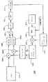
図11には、受信したDTV信号のサンプルを取り入れて使用するためのサンプラの構成1100が示されている。位置実施形態において、サンプラ1100はユーザデバイス102内において実施される。別の構成形態において、サンプラ1100はモニタユニット108内において実施される。当業者において明らかであるように、DTV信号の正確な提示を得るためにサンプリング速度は充分に高いことが必要である。 FIG. 11 shows a
サンプラ1100はDTV信号1102をアンテナ1104で受信する。無線周波数(RF)アンプ/フィルタ1106は受信したDTV信号を増幅およびフィルタリングする。ローカルオシレータクロック1116およびミキサ1108Iおよび1108Qが信号をダウンコンバートして同期(I)および直角位相(Q)サンプルをそれぞれ形成する。IおよびQサンプルはそれぞれ低域通過フィルタ(LPF)1110Iおよび1110Qによってフィルタリングされる。アナログ−デジタルコンバータ(ADC)1112はIおよびQサンプルをデジタル形式に変換する。デジタルIおよびQサンプルはメモリ1114内に記録される。
図12には、サンプラ1100によって形成されたDTV信号サンプルの相関ピークを検索するために使用される非干渉性相関器の構成1200が示されている。別の構成形態において、相関器1200はモニタユニット108内において実施される。 FIG. 12 shows an
相関器1200はメモリ1114からDTV信号のIおよびQサンプルを受領する。相関器1200は中間周波数(IF)においてサンプルを処理する。その他の構成形態において、サンプルはアナログまたはデジタル形式で処理され、中間周波数(IF)またはベースバンドにおいて動作することができる。
コードジェネレータ1202がコードシーケンスを生成する。一実施形態において、コードシーケンスは上昇する余弦波形である。コードシーケンスはATSCフレームにおけるいずれかの既知のデジタルシーケンスとすることができる。一構成形態において、コードは同期コードである。一実施形態において、同期コードはATSCデータフレーム内のフィールド同期セグメントである。別の構成形態において、同期コードはATSCデータフレーム内のデータセグメント内の同期セグメントである。さらに別の構成形態において、同期コードはATSCデータフレーム内のフィールド同期セグメントとATSCデータフレーム内のデータセグメント内の同期セグメントの両方を含んでいる。例えばパイロット、シンボルクロック、キャリア等の別のDTV信号の成分は位置確認のために使用することができる。しかしながら、高い繰り返し速度を有するこれらの信号の使用は固有の曖昧性を生成する。このような曖昧性を解消する技術は当業者において既知である。この種の技術の1つが、M.ラビノビッツ博士による論文、“整数サイクル曖昧性の高速解消のためのGPSと低軌道衛星とを組み合わせた差動キャリアフェーズナビゲーションシステム”(2000年スタンフォード大学電気工学科)の第129−76頁に記載されており、これはここにおいて参照に組み入れてある。 A
ミキサ1204Iおよび1204QはそれぞれIおよびQサンプルをコードジェネレータ1202によって形成されたコードと組み合わせる。ミキサ1204Iおよび1204Qの出力はそれぞれフィルタ1206Iおよび1206Qによってフィルタリングされ加算器1207に付加される。この合計は二乗デバイス1208に付加される。フィルタ1209は一般的な技術に従って非干渉性相関の検波を行う。コンパレータ1210は相関出力を予め設定された閾値と比較する。相関出力が閾値未満に降下すると、サーチコントロール1212が、加算器1214に追加的なパルスをクロック1216によって形成されたクロック波形に付加させ、これによってコードジェネレータを1シンボル進行させ処理を繰り返す。好適な実施例において、クロック波形は10.76MHzの公称クロック速度を有し、クロック速度またはシンボル速度と受信したDTV信号を符合させる。
相関出力が最初に閾値を越えた際に処理が実行される。相関出力を形成したタイムオフセットがそのDTVトランスミッタ106の擬似距離として使用される。 The processing is executed when the correlation output first exceeds the threshold value. The time offset that formed the correlation output is used as the pseudorange for that
レシーバ相関器および整合フィルタ内において、2つの重要なレシーバのデグラデーションの発生源が存在する。ユーザデバイスローカルオシレータはしばしば比較的貧弱な周波数の安定性を有する。この非安定性は2つの異なったレシーバパラメータに影響を与える。第1に、これはレシーバ信号内に周波数オフセットを発生させる。第2に、受信したビットパターンを基準クロックのシンボル速度に対してスリップさせる。これら両方の作用がレシーバの積分時間を制限し、そのためレシーバの処理ゲインを制限する可能性がある。積分時間はレシーバの基準クロックを修正することによって増加させることができる。一実施形態において、遅延ロックループ(DLL)が自動的にレシーバクロックを修正する。 Within the receiver correlator and the matched filter, there are two important sources of receiver degradation. User device local oscillators often have relatively poor frequency stability. This instability affects two different receiver parameters. First, it creates a frequency offset in the receiver signal. Second, it slips the received bit pattern relative to the symbol rate of the reference clock. Both of these effects can limit the integration time of the receiver and thus limit the processing gain of the receiver. The integration time can be increased by modifying the receiver's reference clock. In one embodiment, a delay locked loop (DLL) automatically modifies the receiver clock.
別の実施形態において、NCO(数値制御オシレータ)1218がレシーバのクロック周波数を調整して入力した受信信号クロック周波数と符合させユーザデバイス102内のローカルオシレータのドリフトおよび周波数オフセットを補償する。クロック周波数の精度の増加によって、レシーバ相関器のより長い積分時間およびより良好な動作が可能になる。NCO1218の周波数制御入力は、レシーバシンボルクロック速度同期器、ATSCパイロットキャリアの追跡、またはNCO1218内に装備されたその他のクロック速度選別器等の、可能ないくつかのソースから抽出することができる。 In another embodiment, an NCO (Numerically Controlled Oscillator) 1218 adjusts the clock frequency of the receiver to match the incoming received signal clock frequency to compensate for drift and frequency offset of the local oscillator in the
現在のATSC信号は、先進テレビジョンシステム委員会による2000年3月16日付の“ATSCデジタルテレビジョン規格および改正第1号”に記載されている。このATSC信号は8−aryベスティジアルサイドバンド変調(8VSB)を使用する。ATSC信号のシンボル速度は10.762237MHzであり、これは27.000000MHzのクロックから抽出される。図13にはATSCフレームの構成1300が示されている。フレーム1300はそれぞれ832シンボルからなる合計626個のセグメントからなり、合計520832シンボルを有している。各フレームには2つのフィールド同期セグメントが存在する。各フィールド同期セグメントに312個のデータセグメントが続いている。各セグメントは同期目的で使用される4個のシンボルから始まっている。 The current ATSC signal is described in "ATSC Digital Television Standards and Revision No. 1" dated March 16, 2000 by the Advanced Television System Committee. This ATSC signal uses 8-ary bestial sideband modulation (8VSB). The symbol rate of the ATSC signal is 10.762237 MHz, which is extracted from a 27.000000 MHz clock. FIG. 13 shows the
図14にはフィールド同期セグメントの構成1400が示されている。フレーム1300内の2つのフィールド同期セグメント1400は、第2のフィールド同期セグメント内において63シンボルのミドルセットが反転している点においてのみ異なっている。 FIG. 14 shows the
データセグメントの構成1500が図15に示されている。データセグメント1500の最初の4個のシンボル(これらは−1,1,1,−1である)はセグメント同期に使用される。セグメント1500内のその他の828個のシンボルはデータを搬送する。変調スキームが8VSBであるため、各シンボルは3ビットのコードデータを搬送する。速度2/3符号化スキームが使用されている。 The
本発明の実施形態は、未来型DTV信号の使用拡大を促進する。例えば、ATSC信号特性は高速度16VSB信号を可能にする。しかしながら、16VSB信号は8VSB信号と同じフィールド同期パターンを有している。従って、本発明の単一の実施形態は、8VSBおよび16VSB信号の双方と共に等しく動作するよう設計することができる。 Embodiments of the present invention facilitate the increased use of future DTV signals. For example, the ATSC signal characteristics allow for high speed 16VSB signals. However, the 16VSB signal has the same field synchronization pattern as the 8VSB signal. Thus, a single embodiment of the present invention can be designed to work equally well with both 8VSB and 16VSB signals.
8VSB信号はフィルタリングによって構成される。J.G.プローキス氏の“デジタル通信”1995年マクグローヒル第3版に記載されているように、シンボルパルスの同位相セグメントは上昇する余弦特性を有している。パルスは以下の式で示すことができる: The 8VSB signal is configured by filtering. J. G. FIG. As described in Prokis's "Digital Communications," McGraw-Hill, Third Edition, 1995, in-phase segments of symbol pulses have rising cosine characteristics. The pulse can be represented by the following equation:
U(f)P(f)の応答は以下のように示される: The response of U (f) P (f) is shown as follows:
データが伝送される前に、ATSC信号はさらにキャリア信号を包埋し、これはデータ信号よりも−11.5dB低い出力を有している。このキャリアは信号の干渉性復調を補助する。従って伝送された信号は以下の数式で示すことができる: Before data is transmitted, the ATSC signal further embeds the carrier signal, which has an output of -11.5 dB below the data signal. This carrier assists in coherent demodulation of the signal. Thus, the transmitted signal can be represented by the following equation:
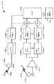
図17には、モニタユニット108の一実施形態が示されている。アンテナ1704はGPS信号1702を受信する。GPSタイムトランスファユニット1706はGPS信号に基づいたマスタクロック信号を生成する。DTVトランスミッタクロックのオフセットを判定するために、NCO(数値制御オシレータ)フィールド同期タイマ1708Aがマスタクロック信号に基づいてマスタ同期信号を生成する。マスタ同期信号は、ATSCセグメント同期信号およびATSCフィールド同期信号のいずれかあるいは両方を含むことができる。一実施形態において、全てのモニタユニット108内のNCOフィールド同期タイマ1708Aが基準の日付および時間に同期する。ユーザユニット102が実行する全ての同じDTVトランスミッタからのDTV信号を単一のモニタユニット108が受信する実施形態において、このモニタユニット108をユーザデバイス102の位置を判定する目的のために他のいずれかのモニタユニットと同期化する必要はない。また、この種の同期化は、全てのモニタステーション108、または全てのDTVトランスミッタが共通のクロックに同期化される場合も必要でなくなる。 FIG. 17 shows an embodiment of the monitor unit 108.
DTVアンテナ1712は複数のDTV信号1710を受信する。別の実施形態においては複数のDTVアンテナが使用される。増幅器(アンプ)1714はDTV信号を増幅する。1つまたは複数のDTVチューナ1716Aないし1716Nは、それぞれ受信されたDTV信号内のDTVチャネルにチューンしDTVチャネル信号を形成する。複数のNCOフィールド同期タイマ1708Bないし1708MのそれぞれはDTVチャネル信号の1つを受信する。複数のNCOフィールド同期タイマ1708Bないし1708MのそれぞれはDTVチャネル信号のチャネル同期信号を抽出する。チャネル同期信号はATSCセグメント同期信号およびATSCフィールド同期信号のいずれかあるいは両方を含むことができる。DTV信号内のパイロット信号およびシンボルクロック信号は捕捉の補助の目的で使用することが理解される。
複数の加算器1718Aないし1718Nのそれぞれはマスタ同期信号とチャネル同期信号のうちの1つの間のクロックオフセットを生成する。プロセッサ1720がフォーマットを行い結果のデータをDTV位置サーバ110に伝送する。一実施形態において、測定される各DTVチャネルに対して、このデータはDTVトランスミッタの識別番号、DTVチャネル番号、DTVトランスミッタの位相中心、およびクロックオフセットを含んでいる。このデータは、無線リンク、およびインターネットを含む多数の方式のいずれかによって伝送することができる。一実施形態において、このデータは予備MPEGパケットとしてこのDTVチャネル自体の上で送信される。 Each of the plurality of
マルチパス現象を緩和する有効な方式の1つは、これより前あるいは後のハードウェアセットアップにおけるサンプリングを使用するよりも、完全な自動相関関数をサンプリングすることである。マルチパス現象は最も早い相関ピークを選択することによって緩和することができる。 One effective way to mitigate the multipath phenomenon is to sample the full autocorrelation function rather than using sampling in earlier or later hardware setups. Multipath phenomena can be mitigated by selecting the earliest correlation peak.
短い遅延をもって位置が計算される場合、単純な方式はソフトウェアレシーバを使用することであり、これはフィルタリングされた信号をサンプリングしこのサンプルをDSP上のファームウェア内で処理する。 If the position is calculated with a short delay, a simple scheme is to use a software receiver, which samples the filtered signal and processes the samples in firmware on the DSP.
図18には、ソフトウェア内における追跡の位置実施形態1800が示されている。アンテナ1802は磁気双極子またはDTV信号を受信することができるその他のアンテナとすることができる。帯域通過フィルタ1804はDTV信号スペクトル全体をLNA1806に伝送する。一実施形態において、フィルタ1804は、帯域通過フィルタがデジタル信号プロセッサ(DSP)1814の制御下において特定のDTVチャネルに対するスペクトルを通過させるように調整することができる。 FIG. 18 shows a
低ノイズ増幅器(LNA)1806は選択された信号を増幅してDTVチャネルセレクタ1808に送信する。DTVチャネルセレクタ1808は、DSP1814の制御下において特定のDTVチャネルを選択し、選択されたチャネル信号を従来の方法によってUHF(超高周波)からIF(中波)へフィルタリングおよびダウンコンバートする。増幅器(AMP)1810は選択されたIFチャネル信号を増幅する。アナログ−デジタルコンバータおよびサンプラ(A/D)1812はDTVチャネル信号s(t)のデジタルサンプルを形成し、このサンプルをDSP1814に伝送する。 A low noise amplifier (LNA) 1806 amplifies the selected signal and sends it to a
次に干渉性ソフトウェアレシーバに対するDSP1814によるDTVチャネル信号処理について記述する。ダウンコンバートされたサンプル信号に対する名目オフセット周波数が仮定される。この信号がベースバンドにダウンコンバートされる場合、名目オフセットは0Hzとなる。このプロセスは、信号s(t)のサンプルに基づいて完全な自動相関関数を生成する。このプロセスは低デューティファクタ信号に対して遥かに効果的に実施することができる。データサンプルの周期をTi、ωinを入力されたサンプリング信号の名目オフセット、ωoffsetを可能な最大のオフセット周波数とすると、ドップラー効果のためシフトおよびオシレータ周波数がドリフトする。プロセスは以下に示す擬似コードを実施する。
・ Rmax=0
・ 複合コード信号を形成Next, DTV channel signal processing by the
・ Rmax = 0
・ Form a composite code signal
・ ω=ωin−ωoffsetからωin+ωoffsetまででステップが
Steps from ω = ωin -ωoffset to ωin + ωoffset
・ 複合混合信号を形成
・
プロセスからの退出に関して、Rstore(τ)は入力信号s(t)と複合コード信号scode(t)との間の相関を蓄積する。Rstore(τ)はより小さいステップのωで検索を行うことによってさらに高精度化することができる。ωの最初のサイズはナイキストレート2π/Tiの半分よりも小さいことが必要である。最大相関出力を形成するタイムオフセットτが擬似距離として使用される。
For exit from the process, Rstore (τ) accumulates the correlation between the input signal s (t) and the composite code signal scode (t). Rstore (τ) can be further refined by performing a search with ω in smaller steps. The initial size of ω needs to be smaller than half the Nyquist rate 2π / Ti . The time offset τ forming the maximum correlation output is used as the pseudorange.
次に、ソフトウェア内における非干渉性相関の生成技術について記述する。この方法は図11および図12のハードウェアレシーバをエミュレートする。ブロック線図においてはIおよびQチャネルが別々に処理されるが、IおよびQ成分は混合信号を形成するためにソフトウェア内で結合されることが理解される。非干渉性相関器が検波を行うため、中間周波数の範囲を検索することは必要でない。このプロセスは以下に示す擬似コードを実行する。
・ 同相および垂直位相コード信号を形成Next, a technique for generating incoherent correlation in software will be described. This method emulates the hardware receiver of FIGS. Although the I and Q channels are processed separately in the block diagram, it is understood that the I and Q components are combined in software to form a mixed signal. Since the incoherent correlator performs the detection, it is not necessary to search the range of intermediate frequencies. This process executes the following pseudo code.
• Form in-phase and vertical-phase code signals
・ τ=0ないしTperまででステップがTsampただしTperは使用されるコードの周期、Tsampはサンプルインタバルであることに対し、
・ 基準コード混合信号を形成
From τ = 0 to Tper and the step is Tsamp where Tper is the period of the code used and Tsamp is the sample interval,
・ Form a reference code mixed signal
・ 入力信号s(t)と基準コード混合信号smix(t)を結合-Combining the input signal s (t) and the reference code mixed signal smix (t)
・ sfit(t)上において検波を実行(例えば積算およびフィルタリングによって)して非干渉性相関を生成:Perform detection (eg, by integration and filtering) on sfit (t) to generate incoherent correlation:
最大相関出力を形成するタイムオフセットτが擬似距離として使用される。
The time offset τ forming the maximum correlation output is used as the pseudorange.
非干渉性相関z(τ)は同相および直角位相成分の両方における信号出力を利用することが理解される。しかしながら、この結果として非干渉性相関を形成する信号の有効帯域幅は半分となる。非干渉性相関器の出力は図19に示されている。上部のプロットは約8×10⁻⁵秒のインタバルに対する相関ピークを示している。下方のプロットは相関ピークの3MHzの有効帯域幅を示している。It is understood that the incoherent correlation z (τ) utilizes the signal power in both the in-phase and quadrature components. However, this results in halving the effective bandwidth of the signal forming the incoherent correlation. The output of the incoherent correlator is shown in FIG. The upper plot shows the correlation peak for the interval of about 8 × 10⁻⁵ seconds. The lower plot shows the 3 MHz effective bandwidth of the correlation peak.
前述したものと類似のソフトウェア内における追跡技術をカリフォルニア州サンノゼ市から発信してカリフォルニア州パオロアルト市の屋内で受信されたDTV伝送に適用した。この例は単に説明目的のものであり、本発明の視点における限定を成すものではない。図20には、サンノゼ市からのKICUチャネル52DTV放送の信号の1msのサンプルにおけるスペクトル例を示している。この信号は27MHzの中央周波数にダウンコンバートされ、これは1秒当たり100メガサンプルのサンプリング速度に対する0.54のデジタル周波数に相当する。この信号は6MHzの帯域幅にデジタル帯域通過フィルタリングされる。 Tracking technology in software similar to that described above originated from San Jose, California and applied to DTV transmissions received indoors in Paolo Alto, California. This example is for illustrative purposes only and does not constitute a limitation in the context of the present invention. FIG. 20 shows an example of a spectrum of a 1 ms sample of a signal of a KICU channel 52 DTV broadcast from the city of San Jose. This signal was downconverted to a center frequency of 27 MHz, which corresponds to a digital frequency of 0.54 for a sampling rate of 100 megasamples per second. This signal is digitally bandpass filtered to a bandwidth of 6 MHz.
結果の6MHz信号の同位相および直角位相成分に対する、計算された自動相関関数が図21に示されている。これは各セグメントの開始における4つのデータ同期シンボルのみに対する相関であることが理解される。 The calculated autocorrelation function for the in-phase and quadrature components of the resulting 6 MHz signal is shown in FIG. It is understood that this is a correlation for only the four data synchronization symbols at the start of each segment.
6MHz信号の特性が図22に示されている。図22には同位相チャネルの自動相関ピークの一部が示されている。曲線の円滑性から、S/N比が高いことが理解される。加えて、ピークの曲率は大きな信号帯域幅を示しており、これによってこの信号のマルチパスに対しての強さをもたらす。 The characteristics of the 6 MHz signal are shown in FIG. FIG. 22 shows a part of the autocorrelation peak of the in-phase channel. It is understood from the smoothness of the curve that the S / N ratio is high. In addition, the curvature of the peak indicates a large signal bandwidth, thereby providing the signal with multipath strength.
図23には相関器1200の動作シミュレーションの結果が示されている。このシミュレーションはウルフマンリサーチによって製造された数学ソフトウェアを使用して導出された。シミュレーション入力はサンプラ1100によってメモリ1114内に記録されたIおよびQデジタルサンプルである。 FIG. 23 shows a result of an operation simulation of the
図23には、10.76MHzの複合サンプル速度および242msの積分時間または10フィールドにおけるシンボル同期サンプルに対する非干渉性相関結果が示されている。このシミュレーションはサンプルが1/2シンボルまたは0.05μsによってオフセットされる最悪のケースである。 FIG. 23 shows the incoherent correlation results for a symbol synchronized sample at a composite sample rate of 10.76 MHz and an integration time of 242 ms or 10 fields. This simulation is the worst case where the samples are offset by シ ン ボ ル symbol or 0.05 μs.
シミュレーションはさらに6MHzの帯域幅で−27dBのガウスノイズおよびS/N比(SNR)を含んでいる。このサンプリングの位相オフセットによって2dBの低下が生じるが、依然として性能は優れている。通常のDTV受信は約+18dBのSNRを必要とする。相関器1200は18+27=45dBの通常のDTV未満のSNRで追跡情報をリカバーすることができる。この結果は整合フィルタが使用されている際にサンプリングクロックの正確な相関を必要とする。しかしながら、時間ゲート遅延ロックループ(DLL)は自動的にそのクロックを受信した信号に同期させ同じ結果を生成する。 The simulation further includes -27 dB of Gaussian noise and a signal-to-noise ratio (SNR) with a bandwidth of 6 MHz. Although this sampling phase offset causes a 2 dB reduction, the performance is still excellent. Normal DTV reception requires an SNR of about +18 dB. The
ETSI位置確認
図24ないし図34には、ヨーロッパ通信規格機構(ETSI)DTV信号を使用するための種々のレシーバが示されている。ETSIはヨーロッパの地上波DTV信号を定義しており、ここではデジタルビデオ放送地上波(DVB−T)信号と呼称する。この新しいDTV信号はマルチプルスタンダードデフィニションTV信号または高精細度信号を割り当てられた8MHzで送信することを可能にする。この新しいDVB−TDTV信号はアナログNTSC−TV信号と全く異なっており、新しい8MHz周波数チャネルにおいて伝送され、全く新しい能力を備えている。ETSI Localization FIGS. 24-34 show various receivers for using the European Telecommunications Standards Institute (ETSI) DTV signal. ETSI defines European terrestrial DTV signals and is referred to herein as digital video broadcast terrestrial (DVB-T) signals. This new DTV signal allows multiple standard definition TV signals or high definition signals to be transmitted at the assigned 8 MHz. This new DVB-TDTV signal is completely different from the analog NTSC-TV signal, is transmitted on a new 8 MHz frequency channel, and has completely new capabilities.
発明者等はDVB−T信号が位置確認に使用できることを認識し、それを実行するための技術を開発した。この技術はDVB−TDTVトランスミッタの周囲で使用することができ、その際のトランスミッタからの距離範囲は典型的なDTV受信範囲よりも遥かに広いものとなる。DTV信号の高い出力のため、この技術は屋内においても手持ち受信機によって使用することができる。 The inventors have recognized that the DVB-T signal can be used for position location and have developed a technique for doing so. This technique can be used around DVB-TDTV transmitters, where the range from the transmitter is much larger than a typical DTV reception range. Due to the high power of the DTV signal, this technique can be used indoors with a hand-held receiver.
ここに開示されている技術および前述のATSC−DTV信号は、当業者において周知であるように、既知のデータシーケンスを含むその他のDTV信号に、単にこの既知のデータシーケンスを受容するように相関器を改変することによって適応することができる。この技術は、さらに衛星ラジオ等の広範なその他の直交周波数分割多重(OFDM)信号にも適用することができる。 The techniques disclosed herein and the aforementioned ATSC-DTV signal may be correlated to other DTV signals, including known data sequences, simply to accept the known data sequence, as is well known in the art. Can be adapted by modifying This technique can also be applied to a wide range of other orthogonal frequency division multiplex (OFDM) signals, such as satellite radio.
GPSのデジタル擬似ノイズコードとは対照的に、DTV信号はわずか数マイルの距離のトランスミッタから受信され、トランスミッタはメガワットレベルのまでの信号を発信する。加えて、DTVアンテナは14dBの単位の大きなアンテナゲインを有する。従って、DTV信号は屋内で受信するために充分な出力を有している。 In contrast to GPS digital pseudo-noise codes, DTV signals are received from transmitters that are only a few miles away, and the transmitters emit signals up to the megawatt level. In addition, DTV antennas have large antenna gains on the order of 14 dB. Thus, the DTV signal has sufficient power to receive indoors.
以下に記すように、本発明の実施形態は“スキャッタパイロット信号”と呼ばれるDVB−T信号の成分を使用する。スキャッタパイロットの使用はいくつかの理由から好適である。第一に、これは屋内およびDTVトランスミッタから大きな距離をおいての位置判定を可能にする。従来のDTVレシーバは一時点に1つのデータ信号のみを使用し、また信号のエネルギーによってDTVトランスミッタからの距離が限定されている。これに対して、本発明の実施形態は、複数のスキャッタパイロット信号のエネルギーを同時に使用し、これによってDTVトランスミッタからの距離が従来のDTVの受信より大きくなっても動作することが可能になる。さらに、スキャッタパイロットはデータによって変調されない。このことは2つの理由から好適である。第1に、スキャッタパイロット内の全ての出力が位置判定に使用可能になり;いずれの出力もデータ専用にはならない。第2にスキャッタパイロットはデータ変調がもたらす減衰の影響を受けることなく長い時間周期で観察可能である。従って、DTVタワーから相当に離れた距離において屋内で信号を追跡する可能性が大幅に拡大する。さらに、デジタル信号プロセッシングの使用によって、この新しい追跡技術を単一の半導体チップ内で実行することが可能となる。 As described below, embodiments of the present invention use a component of the DVB-T signal called a "scatter pilot signal." The use of a scatter pilot is preferred for several reasons. First, it allows for location determination indoors and at large distances from the DTV transmitter. Conventional DTV receivers use only one data signal at a time, and the energy of the signal limits the distance from the DTV transmitter. In contrast, embodiments of the present invention use the energy of multiple scattered pilot signals simultaneously, which allows them to operate at greater distances from a DTV transmitter than conventional DTV reception. Further, the scatter pilot is not modulated by the data. This is preferred for two reasons. First, all outputs in the scatter pilot are available for position determination; none of the outputs are data-only. Second, the scatter pilot can be observed for a long time period without being affected by the attenuation caused by the data modulation. Thus, the possibility of tracking the signal indoors at a considerable distance from the DTV tower is greatly expanded. Furthermore, the use of digital signal processing allows this new tracking technique to be implemented in a single semiconductor chip.
図24には擬似距離測定値の生成に使用するためのレシーバの実施形態2400が示されている。一実施形態において、レシーバ2400はユーザデバイス102内で実施される。別の実施形態において、レシーバ2400はモニタユニット108内で実施される。 FIG. 24 illustrates an
RFサンプラおよび量子化器2406が地域内の各DTV信号2402に対してアンテナ2404、RF増幅器を継続的に調節し、信号をIFまたはベースバンドにダウンコンバートする。広帯域にフィルタリングされた8MHzの帯域幅を有する信号はRFサンプラおよび量子化器2406によってサンプリングおよび量子化される。その後4個あるいはそれより多いシンボルインタバルを有する量子化された信号がメモリ2408内に記録される。好適には、略0.1sまたはそれより長い持続時間を有する、実質的により長いセグメントが平均化時間およびノイズ特性を改善するために使用される。 An RF sampler and
ミキサ2410と相関器および積分器2412とが、継続的に記録された信号の時間セグメントを、スキャッタパイロット発生器2418によって生成された種々のタイムオフセットバージョンの基準スキャッタパイロットキャリアと相関させる。自動相関関数のピークを検出するために、基準信号が予め設定された時間ステップをもって時間的にステップアップされる。このステップの大きさは、自動相関関数のピークを確認するために充分な数の自動相関関数のサンプルを形成し得るように選択する。一実施形態において、自動相関ピークの推定値を得るために最初に大きなステップを使用し;その推定値を高精度化するためにさらに小さいステップが使用される。以下に記述するように、本発明の実施例は1/(1116*20,000)=244nsの間隔の時間サンプルを使用している。相関器サーチコントロール2420が自動相関関数における主要なピークを検索し、検出した場合その擬似距離の測定値をデジタル化された形式に変換する。レシーバ2400はその後その地域内の他のDTVタワーから受信可能な他のDTV信号2402上で同じ機能のセットを継続的に実施する。同じDTVタワーから送信された信号の測定を複数行う必要はない。その後、3つまたはそれより多い擬似距離測定値がデジタル携帯電話またはその他の無線リンクによってDTV位置サーバ110に伝送される。
加入者のハンドセットあるいはその他のデバイスの位置確認はその加入者が位置確認を必要とする場合にのみ実行されることが理解される。ゆっくり歩行、自動車でゆっくり走行、あるいは屋内または屋外に座っていて、緊急事態におかれている加入者に対して、この位置情報が測定されることは極稀である。従って、電池あるいはその他の電源は極めて小さいものとなる。 It will be appreciated that localization of the subscriber's handset or other device will only be performed if the subscriber requires localization. It is very unlikely that this location information will be measured for a subscriber who is in an emergency, walking slowly, driving slowly in a car, or sitting indoors or outdoors. Thus, batteries or other power sources are extremely small.
レシーバ2400はデジタル信号の合計の相互相関を実施するが、別の実施形態において例えばFFT/DFT(高速フーリエ変換/離散フーリエ変換)を使用することにより回路を簡略化し得ることは当業者において明らかである。さらに、レシーバ2400は中間周波数(IF)でサンプルを処理するが、別の実施形態においてサンプルはアナログあるいはデジタル形式で処理され、またIFまたはベースバンドで動作することができる。さらに別の実施形態においてサンプルは周波数領域で処理される。
DVB−T構造内の他の信号も位置確認に使用することができる。例えば、連続的なパイロット信号に対してワイドレイニング技術を適用することができる。しかしながら、この種のワイドレイニング等の技術は固有の周期的曖昧性解消を含んでいる。この種の曖昧性を解消する技術は周知である。この種の技術の1つが、M.ラビノビッツ博士による論文、“整数サイクル曖昧性の高速解消のためのGPSと低軌道衛星とを組み合わせた差動キャリアフェーズナビゲーションシステム”(2000年スタンフォード大学電気工学科)の第59−76頁に記載されており、これはここにおいて参照に組み入れてある。 Other signals in the DVB-T structure can also be used for localization. For example, a wide-laying technique can be applied to a continuous pilot signal. However, this type of technique, such as wide laying, involves inherent periodic disambiguation. Techniques for resolving this type of ambiguity are well known. One such technique is described in M.K. A paper by Dr. Rabinowitz, "Differential Carrier Phase Navigation System Combining GPS and Low Earth Orbit Satellites for Fast Resolution of Integer Cycle Ambiguity," (2000 Stanford University Electrical Engineering), pp. 59-76. And this is incorporated herein by reference.
レシーバ相関器および整合フィルタ内において、2つの重要なレシーバのデグラデーションの発生源が存在する。ユーザデバイスローカルオシレータはしばしば比較的貧弱な周波数の安定性を有する。この非安定性は2つの異なったレシーバパラメータに影響を与える。第1に、これはレシーバ信号内に周波数オフセットを発生させる。第2に、受信したビットパターンを基準クロックのシンボル速度に対してスリップさせる。これら両方の作用がレシーバの積分時間を制限し、そのためレシーバの処理ゲインを制限する可能性がある。積分時間はレシーバの基準クロックを修正することによって増加させることができる。一実施形態において、遅延ロックループ(DLL)が自動的にレシーバクロックを修正する。 Within the receiver correlator and the matched filter, there are two important sources of receiver degradation. User device local oscillators often have relatively poor frequency stability. This instability affects two different receiver parameters. First, it creates a frequency offset in the receiver signal. Second, it slips the received bit pattern relative to the symbol rate of the reference clock. Both of these effects can limit the integration time of the receiver and thus limit the processing gain of the receiver. The integration time can be increased by modifying the receiver's reference clock. In one embodiment, a delay locked loop (DLL) automatically modifies the receiver clock.
別の実施形態において、NCO(数値制御オシレータ)2414がレシーバのクロック周波数を調整して入力した受信信号クロック周波数と符合させユーザデバイス102内のローカルオシレータのドリフトおよび周波数オフセットを補償する。クロック周波数の精度の増加によって、レシーバ相関器のより長い積分時間およびより良好な動作が可能になる。NCO2414の周波数制御入力は、マスタクロック2416、レシーバシンボルクロック速度同期器、DVN−Tパイロットキャリアの追跡、またはNCOクロック2414内に装備されたその他のクロック速度選別器等から抽出することができる。 In another embodiment, a numerically controlled oscillator (NCO) 2414 adjusts the clock frequency of the receiver to match the incoming received signal clock frequency to compensate for drift and frequency offset of the local oscillator within the
現在のDVB−T信号はデジタルビデオ放送(DVB)と呼ばれる文書に説明されており;デジタル地上波テレビのためのフレーミング構造、チャネルコーディングおよび変調が記載されており、文書番号はETSI EN300744第1.4.1版(2001年1月)である。DVB−T信号は、1512または6048の分離したキャリーを使用して188バイトMPEG(ムービングピクチャエクスパートグループ)を搬送する複合垂直周波数分割多重(OFDM)信号である。これらの成分の殆どはビデオTV信号の不規則データ変調を搬送するものであり、低い信号レベルにおいては精密な追跡のために利用しにくいものである。位置確認の目的のためには、ユーザデバイスはDVB−T信号の全ての情報内容が受信可能でない場所に位置していてもよいことが理解される。 Current DVB-T signals are described in a document called Digital Video Broadcasting (DVB); framing structures, channel coding and modulation for digital terrestrial television are described, and the document number is
しかしながら、DVB−TDTV信号は、ここに記述する位置確認に使用可能な追加的な成分を埋包して含むことが可能である。例えば、DVB−TDTV信号は2つのタイプの周期的広帯域パイロット信号を含むことができる。この信号はいずれも連続的なパイロットキャリアの集合およびスキャッタパイロットキャリアの集合を含む。DVB−T信号は2つのモード:2Kおよび8Kを有する。これら2つのモードのパラメータのいくつかを下の表2に記す。本発明の実施形態は8K信号に関して説明するが、この技術は2K信号にも適用可能である。 However, the DVB-TDTV signal can include embedded additional components that can be used for localization as described herein. For example, a DVB-TDTV signal can include two types of periodic wideband pilot signals. Each of these signals includes a continuous set of pilot carriers and a set of scattered pilot carriers. The DVB-T signal has two modes: 2K and 8K. Some of the parameters for these two modes are listed in Table 2 below. Although embodiments of the present invention are described with respect to 8K signals, this technique is also applicable to 2K signals.
8KモードにおけるDVB−T連続パイロット信号は、以下に記述されるようにPNシーケンスによって選択された一定の基準バイナリ±1の振幅をそれぞれ有する177個のキャリアとすることができる。キャリアは1116Hzの間隔で配置されている。最初の50個のキャリア周波数のキャリア番号が図25に示されている。1つのキャリアの周波数はキャリア番号と1116Hzの積を取ることによって求められる。図26には連続するパイロットキャリアの最初の50個のキャリアが示されている。垂直軸はキャリア番号である。いずれか2つの連続するパイロットキャリアの間の最小周波数オフセットは3×1116Hzであり、これはこれらの連続するキャリアの時間曖昧性を決定する。この信号は一般的に距離測定に使用されるサイドトーンレンジング信号になぞらえることができる。しかしながら、これは出力が177の分離したキャリアによって分割される点において異なっている。しかしながら、これに代えてこの信号をFFT手法によって形成された177個のキャリアの合成基準波形と相関させることができる。しかしながら、合成連続パイロット信号は貧弱な自動相関関数を有しており、図27に示されるように多数の大きなスペクトルサイドローブを伴っている。 The DVB-T continuous pilot signal in the 8K mode may be 177 carriers each having a fixed reference binary ± 1 amplitude selected by a PN sequence as described below. Carriers are arranged at intervals of 1116 Hz. The carrier numbers of the first 50 carrier frequencies are shown in FIG. The frequency of one carrier is obtained by taking the product of the carrier number and 1116 Hz. FIG. 26 shows the first 50 carriers of consecutive pilot carriers. The vertical axis is the carrier number. The minimum frequency offset between any two consecutive pilot carriers is 3 × 1116 Hz, which determines the time ambiguity of these consecutive carriers. This signal can be compared to a side tone ranging signal generally used for distance measurement. However, this differs in that the output is divided by 177 separate carriers. However, alternatively, this signal can be correlated with a composite reference waveform of 177 carriers formed by the FFT technique. However, the synthesized continuous pilot signal has a poor autocorrelation function, with many large spectral sidelobes as shown in FIG.
図27には、8Kモードにおける177個の並列キャリアを有する合成連続パイロットキャリアの機能が示されている。水平軸上の時間の増加は1/1116sで与えられている。信号は1116×20,000サンプル/sでサンプリングされる。しかしながら、この信号のサイドローブレベルは非常に高く、0.2超の大きさからなる多くのピークを伴っている。 FIG. 27 shows the function of a combined continuous pilot carrier having 177 parallel carriers in the 8K mode. The time increase on the horizontal axis is given in 1 / 1116s. The signal is sampled at 1116 × 20,000 samples / s. However, the sidelobe level of this signal is very high, with many peaks of magnitude greater than 0.2.
8Kのスキャッタパイロットキャリアは568個の均一に分配されたパイロットキャリアの集合であり、各周波数がチャープ状にホップして4つの連続する周波数にわたったものである。従って、各パイロットは12×1116Hzの積算である周波数から開始し、シンボル持続時間(1/1116s)の残りの部分にわたってこの周波数に留まる。次のシンボルに対してパイロットは新しい周波数にホップし、これは3×1116Hz高いものとなり、±1符号を有する。パイロットはこの増加を全部で3回の増加繰り返しその後元の周波数に回帰する。この568個のスキャッタパイロットのうちの最初の5個の周波数ホップが図28に示されている。パイロットキャリアの各時間増加において周波数において1116Hzの増加が3回行われる。6816/12=568スキャッタパイロットのそれぞれが12×1116=13,392Hzで離間している。2Kモードにおいては53,568Hzで離間した142個のスキャッタパイロットが存在する。 An 8K scattered pilot carrier is a set of 568 uniformly distributed pilot carriers, each frequency hopping in a chirp and spanning four consecutive frequencies. Thus, each pilot starts at a frequency that is an integration of 12 × 1116 Hz and remains at this frequency for the remainder of the symbol duration (1/1116 s). For the next symbol, the pilot hops to the new frequency, which is 3 × 1116 Hz higher and has ± 1 sign. The pilot repeats this increase a total of three times and then returns to the original frequency. The first five frequency hops of the 568 scatter pilots are shown in FIG. There are three 1116 Hz increases in frequency at each time increment of the pilot carrier. Each of the 6816/12 = 568 scatter pilots is separated by 12 × 1116 = 13,392 Hz. In the 2K mode, there are 142 scatter pilots spaced at 53,568 Hz.
各パイロットキャリアは、±1符号で11ステージシフトレジスタのPNシーケンスによって以下の多項式をもって支配されるものとして与えられる: Each pilot carrier is given as being governed by the following polynomial by a PN sequence of 11 stage shift registers with ± 1 codes:
従って、各スキャッタパイロットの周波数は以下のようにtおよびpの関数として示すことができる: Thus, the frequency of each scatter pilot can be shown as a function of t and p as follows:
ここでpはパイロットの番号、n[t]は量子化された時間インタバルである:
Where p is the pilot number and n [t] is the quantized time interval:
図30には、別の視点でスキャッタパイロットキャリアが示されている。図30において、斜線は568個の8Kスキャッタパイロットキャリアを示しており、これは6814/4=1704個のシンボルインタバルの7.61NHz(6816のキャリア番号)の帯域全体にわたってステップ上にチャープしている。各チャープキャリアは7.61MHzの周波数帯をステップ状に掃引する。ここで示された数は8Kモードに対応するものであり、ここでシンボル持続時間は896μsである。2Kモードに対応する数字はカッコ内に示されており、ここでシンボル持続時間は224μsである。 FIG. 30 shows a scattered pilot carrier from another viewpoint. In FIG. 30, the hatched lines indicate 568 8K scatter pilot carriers, which are chirped stepwise over the entire band of 7.61 NHz (carrier number of 6816) of 6814/4 = 1704 symbol intervals. . Each chirp carrier sweeps the frequency band of 7.61 MHz stepwise. The numbers shown here correspond to the 8K mode, where the symbol duration is 896 μs. The number corresponding to the 2K mode is shown in parentheses, where the symbol duration is 224 μs.
この信号は図31−33に示されるように極めて良好な自動相関関数を有している。図31には568個の周波数がホップするスキャッタパイロットキャリアの複合集合の自動相関関数が示されている。複合信号は1116×2000=22.32MHzの速度でサンプリングされる。従って、スキャッタパイロットキャリアの4シンボルの時間増加周期にわたって80,000個のサンプルが存在する。ダブレットの下側にある4つのサイドローブを除いて、この信号は非常に低いサイドローブ相互相関を有することが理解される。図32および33には遥かに小さな時間増加にわたって詳細が示されている。 This signal has a very good autocorrelation function as shown in FIGS. FIG. 31 shows an autocorrelation function of a complex set of scattered pilot carriers in which 568 frequencies hop. The composite signal is sampled at a rate of 1116 × 2000 = 22.32 MHz. Thus, there are 80,000 samples over a time increment of 4 symbols of the scatter pilot carrier. It is understood that this signal has a very low sidelobe cross-correlation, except for the four sidelobes below the doublet. 32 and 33 show details over a much smaller time increment.
図32には、最初の100回の時間増加にわたって観察されたスキャッタパイロット合成信号の詳細構造が示されている。ピーク以外の部分の自動相関関数が低いレベルにあることが理解される。 FIG. 32 shows the detailed structure of the scattered pilot combined signal observed over the first 100 time increments. It can be seen that the autocorrelation function in the parts other than the peak is at a low level.
図33には、スキャッタパイロット合成キャリアのダブレットサイドボードの構造が示されている。再び、メインピークおよび4つのサイドローブピーク以外の部分の自動相関関数数値が極めて低いことが理解される。 FIG. 33 shows the structure of the doublet sideboard of the scattered pilot combining carrier. Again, it can be seen that the autocorrelation function values other than the main peak and the four sidelobe peaks are extremely low.
図34には、モニタユニット108の実施形態3400が示されている。アンテナ3404がGPS信号3402を受信する。GPSタイムトランスファユニット3406がGPS信号に基づいてマスタクロック信号を形成する。DTVトランスファクロックのオフセットを決定するために、NCO(数値制御オシレータ)コード同期タイマ3408Aがマスタクロック信号に基づいてマスタ同期信号を生成する。マスタ同期信号はDVB−Tスキャッタパイロットキャリアを含むことができる。一実施形態において、全てのモニタユニット108におけるNCOフィールド同期タイマ3408Aは基準の日付および時間に同期される。ユーザユニット102が実行する全ての同じDTVトランスミッタからのDTV信号を単一のモニタユニット108が受信する実施形態において、このモニタユニット108をユーザデバイス102の位置を判定する目的のために他のいずれかのモニタユニットと同期化する必要はない。また、この種の同期化は、全てのモニタステーション108、または全てのDTVトランスミッタが共通のクロックに同期化される場合も必要でなくなる。 FIG. 34 shows an
DTVアンテナ3412は複数のDTV信号3410を受信する。別の実施形態においては複数のDTVアンテナが使用される。増幅器(アンプ)3414はDTV信号を増幅する。1つまたは複数のDTVチューナ3416Aないし3416Nは、それぞれ受信されたDTV信号内のDTVチャネルにチューンしDTVチャネル信号を形成する。複数のNCOフィールド同期タイマ3408Bないし3408MのそれぞれはDTVチャネル信号の1つを受信する。複数のNCOフィールド同期タイマ3408Bないし3408MのそれぞれはDTVチャネル信号のチャネル同期信号を抽出する。チャネル同期信号はATSCセグメント同期信号およびATSCフィールド同期信号のいずれかあるいは両方を含むことができる。一実施例において、DTV−T信号内の連続するパイロット信号およびシンボルクロック信号は捕捉の補助の目的で使用される。
複数の加算器3418Aないし3418Nのそれぞれはマスタ同期信号とチャネル同期信号のうちの1つの間のクロックオフセットを生成する。プロセッサ3420がフォーマットを行い結果のデータをDTV位置サーバ110に伝送する。一実施形態において、測定される各DTVチャネルに対して、このデータはDTVトランスミッタの識別番号、DTVチャネル番号、DTVトランスミッタの位相中心、およびクロックオフセットを含んでいる。このデータは、無線リンク、およびインターネットを含む多数の方式のいずれかによって伝送することができる。一実施形態において、このデータは予備MPEGパケットとしてこのDTVチャネル自体の上で送信される。 Each of the plurality of
別の実施形態において、レシーバはソフトウェアベースのものである。例えば、図18のレシーバ1800は入力したDTV信号を処理するようにプログラムすることができる。 In another embodiment, the receiver is software based. For example, the
次に干渉性ソフトウェアレシーバに対するDSP1714によるDTVチャネル信号処理について記述する。ダウンコンバートされたサンプル信号に対する名目オフセット周波数が仮定される。この信号がベースバンドにダウンコンバートされる場合、名目オフセットは0Hzとなる。このプロセスは、信号s(t)のサンプルに基づいて完全な自動相関関数を生成する。このプロセスは低デューティファクタ信号に対して遥かに効果的に実施することができる。サンプリングされたデータの周期をTi、ωinを入力されたサンプリング信号の名目オフセット、ωoffsetを可能な最大のオフセット周波数とすると、ドップラー効果のためシフトおよびオシレータ周波数がドリフトする。プロセスは以下に示す擬似コードを実施する。
・ Rmax=0
・ 複合コード信号を形成Next, DTV channel signal processing by the
・ Rmax = 0
・ Form a composite code signal
・ F{scode}*を計算、ここでFはフーリエ変換の演算子、*は共役オペレータある。
・ ω=ωin−ωoffsetからωin+ωoffsetまででステップがπ/2T1に対して
・ 複合混合信号を形成
Calculate F scode }* , where F is the Fourier transform operator and* is the conjugate operator.
From ω = ωin −ωoffset to ωin + ωoffset , the step is π / 2T1・ Composite mixed signal is formed
・
プロセスからの退出に関して、Rstore(τ)は入力信号s(t)と複合コード信号scode(t)との間の相関を蓄積する。Rstore(τ)はより小さいステップのωで検索を行うことによってさらに高精度化することができる。ωの最初のサイズはナイキストレート2π/Tiの半分よりも小さいことが必要である。最大相関出力を形成するタイムオフセットτが擬似距離として使用される。
For exit from the process, Rstore (τ) accumulates the correlation between the input signal s (t) and the composite code signal scode (t). Rstore (τ) can be further refined by performing a search with ω in smaller steps. The initial size of ω needs to be smaller than half the Nyquist rate 2π / Ti . The time offset τ forming the maximum correlation output is used as the pseudorange.
追加的な位置確認例
本発明の多数の実施例ついて記述した。しかしながら、本発明の精神および視点から逸脱することなく種々の設計変更が可能であることが理解される。例えば、特定のATSCおよびDVB−T信号に関して多くの特徴を記述した。しかしながら、本発明は、ジャパニーズインテグレーテッドデジタル地上波放送(ISDB−T)等のその他のDTV信号にも適用可能である。Additional Localization Examples A number of embodiments of the invention have been described. Nevertheless, it will be understood that various modifications may be made without departing from the spirit and perspective of the invention. For example, many features have been described with respect to particular ATSC and DVB-T signals. However, the present invention is also applicable to other DTV signals such as Japanese Integrated Digital Terrestrial Broadcasting (ISDB-T).
別の例において、本発明はデジタル電子回路、またはコンピュータハードウェア、ファームウェア、ソフトウェア、またはそれらの組み合わせによって実施することができる。種々の信号および信号処理技術がデジタルあるいはアナログ領域において実施可能である。本発明の装置は、プログラマブルプロセッサによって実行するために機械読取可能な記憶デバイス内に実装されたコンピュータプログラムとして実施することができ;また本発明の方法ステップは命令プログラムを実行するプロセッサによって本発明の機能を実行しデータを入力して出力を形成することによって実施することができる。本発明は、受信データに結合されデータ記憶システムから、またはこれに対して命令およびデータを送受信する少なくとも1つのプログラマブルプロセッサと、少なくとも1つの入力デバイスおよび少なくとも1つの出力デバイスを含んだプログラマブルシステム上で実行可能な1つまたは複数のコンピュータプログラム内で有効に実施することが可能である。各コンピュータプログラムは高級手続き言語または目的指向プログラム言語内において実行するか、あるいは必要に応じてアセンブリまたは機械語内において実行することができ;この言語はコンパイルされたものあるいは翻訳された言語とすることができる。好適なプロセッサには、例えば、汎用または特定用途のマイクロプロセッサの両方が含まれる。一般的に、プロセッサは読取り専用メモリ(ROM)および/またはランダムアクセスメモリ(RAM)から命令およびデータを受信する。一般的に、コンピュータはデータファイルを記憶するために1つまたは複数の大容量記憶装置を備えており;これは内蔵ハードディスクまたは取り外し可能なディスク等の磁気ディスク;光磁気ディスク;および光ディスク等を含んでいる。コンピュータプログラム命令およびデータを実装するために適した記憶装置は、例えばEPROM、EEPROM、およびフラッシュメモリデバイス等を含む全てのタイプの不揮発メモリ;内蔵ハードディスクまたは取り外し可能なディスク等の磁気ディスク;光磁気ディスク;およびCD−ROMディスクとすることができる。前述のもののいずれかは、ASIC(特定用途向け集積回路)によって補完されるかあるいはその中に組み込むことができる。 In another example, the invention can be implemented by digital electronic circuits or computer hardware, firmware, software, or a combination thereof. Various signals and signal processing techniques can be implemented in the digital or analog domain. The apparatus of the present invention may be embodied as a computer program implemented in a machine-readable storage device for execution by a programmable processor; and the method steps of the present invention may be implemented by a processor executing an instruction program. It can be implemented by performing a function and inputting data to form an output. The present invention resides on a programmable system including at least one programmable processor coupled to received data for transmitting and receiving instructions and data from or to a data storage system, and at least one input device and at least one output device. It can be effectively implemented in one or more executable computer programs. Each computer program may execute in a high-level procedural language or an object-oriented programming language, or may be executed in an assembly or machine language as required; the language may be a compiled or translated language Can be. Suitable processors include, for example, both general purpose and special purpose microprocessors. Generally, a processor will receive instructions and data from a read-only memory (ROM) and / or a random access memory (RAM). Generally, computers include one or more mass storage devices for storing data files; this includes magnetic disks such as internal hard disks or removable disks; magneto-optical disks; and optical disks and the like. In. Suitable storage devices for implementing computer program instructions and data include, for example, all types of non-volatile memory including EPROM, EEPROM, and flash memory devices; magnetic disks such as internal hard disks or removable disks; magneto-optical disks And a CD-ROM disk. Any of the foregoing can be supplemented by, or incorporated in, ASICs (application-specific integrated circuits).
別の例として、同位相および直角位相チャネルを使用してATSC信号を追跡する方法について記述したが、同位相チャネルのみ、直角位相チャネルのみ、あるいはそれらの組合せを使用して精密な追跡を提供し得ることが理解される。 As another example, a method for tracking an ATSC signal using in-phase and quadrature channels has been described, but providing precise tracking using only in-phase channels, only quadrature channels, or a combination thereof. It will be appreciated that you get.
さらに、多様な形式の一般的な遅延ロックループ(DLL)を使用しまた種々のタイプの整合フィルタを使用するDTV信号の追跡方法があることが理解される。 Further, it will be appreciated that there are methods of tracking DTV signals using various types of common delay locked loops (DLLs) and using various types of matched filters.
本発明の実施形態は、DTV信号の低いデューティファクタを多様な方式で利用する。例えば、1つの実施形態は時間ゲート遅延ロックループ(DLL)を使用しており、これは、J.J.スピルカー・ジュニア氏の“衛星によるデジタル通信”(プレンティスホール、イングルウッドクリフ、ニュージャージー州、1977年第18−6章)に記載されている。他の実施形態は、干渉性、非干渉性、準干渉性DLLを含む多様なDLLを使用しており、これはJ.J.スピルカー・ジュニア氏の“衛星によるデジタル通信”(プレンティスホール、イングルウッドクリフ、ニュージャージー州、1977年第18−6章)、B.パーキンソン氏およびJ.スピルカー・ジュニア氏による“グローバルポジショニングシステム−理論および適用”(AIAA、ワシントンDC、1996年第1巻第17章)、およびJ.J.スピルカー・ジュニア氏による“信号追跡理論の基本”等に記載されている。他の実施形態は再循環整合フィルタ等の種々のタイプの整合フィルタを使用する。 Embodiments of the present invention use the low duty factor of the DTV signal in various ways. For example, one embodiment uses a time gated delay locked loop (DLL), which is described in J. See Spiller Jr., "Digital Communications by Satellite" (Prentice Hall, Inglewood Cliff, NJ, Chapters 18-6, 1977). Other embodiments use a variety of DLLs, including coherent, non-coherent, and quasi-coherent DLLs, which are described in US Pat. J. Spilker Jr., "Digital Communications with Satellites" (Prentice Hall, Inglewood Cliff, NJ, Chapters 18-6, 1977); Parkinson and J.M. "Global Positioning System-Theory and Application" by Spielker Jr. (AIAA, Washington DC, 1996, Vol. 1, Chapter 17); J. It is described in "The Basics of Signal Tracking Theory" by Spielker Jr. Other embodiments use various types of matched filters, such as recirculating matched filters.
最後の例として、いくつかの実施形態においてDTVサーバ110は、例えばDTVトランスミッタから取得可能な擬似距離等のシステムレベルで取得可能な冗長信号を使用し、各DTVチャネルおよび擬似距離を認可するための追加的なチェックを実行し、誤ったDTVチャネルを確認する。この技術の一つが一般的なレシーバ自律保全モニタリング(RAIM)である。 As a final example, in some embodiments, the
従って、本発明の視点の範囲内においてその他の実施形態も可能である。 Thus, other embodiments are possible within the scope of the present invention.
Claims (59)
Translated fromJapaneseデバイスの位置にアクセスし、この位置はデバイスと複数のデジタルテレビジョン(DTV)トランスミッタとの間の擬似距離から判定されるものであり、この擬似距離はデバイスによって受信されたDTVトランスミッタからの放送DTV信号から計算し;
デバイスの位置において物理的サービスを提供することからなる方法。A way to provide physical services to the device user:
Accessing the location of the device, the location being determined from a pseudorange between the device and a plurality of digital television (DTV) transmitters, the pseudorange being received by the device from the broadcast DTV from the DTV transmitter; Calculate from the signal;
A method comprising providing a physical service at a device location.
キーコードをデバイスに伝送することを含み、そのキーコードがその位置での物理的サービスの提供を許可する請求項1記載の方法。The provision of physical services is:
The method of claim 1, comprising transmitting a key code to the device, wherein the key code authorizes the provision of a physical service at the location.
物理的サービスの地域サービスプロバイダに連絡し;
その地域サービスプロバイダに物理的サービスをその位置で提供することを許可する、
ことを含む請求項1記載の方法。The provision of physical services is:
Contact the local service provider of the physical service;
Allow the local service provider to provide physical services at that location,
The method of claim 1 comprising:
デバイスの位置にアクセスし、この位置はデバイスと複数のデジタルテレビジョン(DTV)トランスミッタとの間の擬似距離から判定されるものであり、この擬似距離はデバイスによって受信されたDTVトランスミッタからの放送DTV信号から計算し;
デバイスの位置に従ってサービスを提供することからなる方法。Here's how to provide services based on device location:
Accessing the location of the device, the location being determined from a pseudorange between the device and a plurality of digital television (DTV) transmitters, the pseudorange being received by the device from the broadcast DTV from the DTV transmitter; Calculate from the signal;
A method consisting of providing services according to the location of the device.
デバイスが放送DTV信号から擬似距離を計算し;
擬似距離に基づいてデバイスが位置を判定する、
ことを含む請求項18記載の方法。To access the device location:
The device calculates a pseudorange from the broadcast DTV signal;
The device determines a position based on the pseudorange,
19. The method of claim 18, comprising:
デバイスがDTV位置サーバから位置を受信することを含む請求項18記載の方法。To access the device location:
19. The method of claim 18, including the device receiving a location from a DTV location server.
サービスプロバイダシステムがデバイスから位置を受信することを含む請求項21記載の方法。To access the device location:
22. The method of claim 21, including the service provider system receiving a location from the device.
サービスプロバイダシステムがDTV位置サーバから位置を受信することを含む請求項21記載の方法。To access the device location:
22. The method of claim 21 including a service provider system receiving a location from a DTV location server.
サービスプロバイダがデバイスの位置に従ってサービスのためのキーコードを決定し、このキーコードはサービスの提供を可能にするものであり;
サービスプロバイダシステムはこのキーコードをデバイスに伝送する、
ことを含む請求項13記載の方法。Services are provided:
The service provider determines a key code for the service according to the location of the device, and the key code enables provision of the service;
The service provider system transmits this key code to the device,
14. The method of claim 13, comprising:
サービスの地域サービスプロバイダに連絡し;
その地域サービスプロバイダにその位置でサービスを提供することを許可する、
ことを含む請求項13記載の方法。Services are provided:
Contact the local service provider for the service;
Allow the local service provider to provide services at that location,
14. The method of claim 13, comprising:
サービスの要求を受信し;
この要求に応答してのみサービスを提供する、
ことを含む請求項13記載の方法。Services are provided:
Receiving a request for service;
Provide services only in response to this request,
14. The method of claim 13, comprising:
デバイスの位置にアクセスする手段を備え、この位置はデバイスと複数のデジタルテレビジョン(DTV)トランスミッタとの間の擬似距離から判定されるものであり、この擬似距離はデバイスによって受信されたDTVトランスミッタからの放送DTV信号から計算し;
デバイスの位置に従ってサービスを提供する手段を備える装置。A device that provides services based on device location:
Means for accessing a location of the device, the location being determined from a pseudorange between the device and the plurality of digital television (DTV) transmitters, the pseudorange being determined by a DTV transmitter received by the device. Calculated from the broadcast DTV signal of
An apparatus comprising means for providing a service according to the location of the device.
放送DTV信号から擬似距離を計算する手段と;
擬似距離に基づいて位置を判定する手段を備え;
ここで擬似距離を計算する手段と位置を判定する手段はデバイス内に組み込まれている請求項36記載の装置。The means to access the device location are:
Means for calculating a pseudorange from the broadcast DTV signal;
Means for determining a position based on the pseudorange;
37. The apparatus according to claim 36, wherein the means for calculating the pseudorange and the means for determining the position are incorporated in the device.
DTV位置サーバから位置を受信する手段を備え、前記手段がデバイス内に組み込まれている請求項36記載の装置。The means to access the device location are:
37. The apparatus of claim 36, further comprising means for receiving a location from a DTV location server, said means incorporated within the device.
位置を受信する手段を備えており、前記手段がデバイス内に組み込まれている請求項39記載の装置。The means to access the device location are:
40. The apparatus of claim 39, further comprising means for receiving a location, said means incorporated in the device.
デバイスの位置に従ってサービスのためのキーコードを決定する手段を備え、このキーコードはサービスの提供を可能にするものであり;
さらにこのキーコードをデバイスに伝送する手段を備える請求項32記載の装置。The means of providing the service are:
Means for determining a key code for the service according to the location of the device, said key code enabling provision of the service;
33. The apparatus of claim 32, further comprising means for transmitting the key code to the device.
サービスの地域サービスプロバイダに連絡する手段と;
その地域サービスプロバイダにその位置でサービスを提供することを許可する手段を備える請求項32記載の装置。The means of providing the service are:
Means for contacting the local service provider of the service;
33. The apparatus of claim 32, comprising means for permitting the local service provider to provide service at the location.
デバイスの位置にアクセスする手段を備え、この位置はデバイスと複数のデジタルテレビジョン(DTV)トランスミッタとの間の擬似距離から判定されるものであり、この擬似距離はデバイスによって受信されたDTVトランスミッタからの放送DTV信号から計算し;
さらにデバイスの位置におけるサービスの提供を可能にする手段を備える装置。Devices that enable the provision of physical services:
Means for accessing a location of the device, the location being determined from a pseudorange between the device and the plurality of digital television (DTV) transmitters, the pseudorange being determined by a DTV transmitter received by the device. Calculated from the broadcast DTV signal of
Apparatus further comprising means enabling provision of services at the location of the device.
物理的サービスをその位置に配送する手段を備える請求項49記載の装置。The means by which the service can be provided are:
50. The apparatus of claim 49, comprising means for delivering a physical service to the location.
キーコードをデバイスに送信する手段を備え、このキーコードがその位置における物理的サービスの提供を許可する請求項49記載の装置。The means by which the service can be provided are:
50. The apparatus of claim 49, further comprising means for transmitting a key code to the device, the key code authorizing the provision of a physical service at the location.
サービスの地域サービスプロバイダに連絡する手段と;
その地域サービスプロバイダにその位置でサービスを提供することを許可する手段を備える請求項49記載の装置。The means by which the service can be provided are:
Means for contacting the local service provider of the service;
50. The apparatus of claim 49, comprising means for permitting the local service provider to provide service at the location.
複数のDTVトランスミッタから放送DTV信号を受信して受信したDTV信号から擬似距離を計算するデバイスと;
擬似距離からデバイスの位置を判定するためのDTV位置サーバと;
デバイスの位置に従ってサービスを提供するためのサービスプロバイダシステムを備えるシステム。A system that provides services based on device location:
A device for receiving a broadcast DTV signal from a plurality of DTV transmitters and calculating a pseudorange from the received DTV signal;
A DTV location server for determining the location of the device from the pseudorange;
A system comprising a service provider system for providing services according to device location.
デバイス自体がサービスを提供することによってサービスプロバイダシステムとして機能する請求項56記載の方法。The device itself acts as a DTV location server by determining the location from the pseudorange; and
The method of claim 56, wherein the device itself functions as a service provider system by providing a service.
Applications Claiming Priority (9)
| Application Number | Priority Date | Filing Date | Title |
|---|---|---|---|
| US26567501P | 2001-02-02 | 2001-02-02 | |
| US28126901P | 2001-04-03 | 2001-04-03 | |
| US28127001P | 2001-04-03 | 2001-04-03 | |
| US29381301P | 2001-05-25 | 2001-05-25 | |
| US29381201P | 2001-05-25 | 2001-05-25 | |
| US29364601P | 2001-05-25 | 2001-05-25 | |
| US88715801A | 2001-06-21 | 2001-06-21 | |
| US09/932,010US7126536B2 (en) | 2001-02-02 | 2001-08-17 | Position location using terrestrial digital video broadcast television signals |
| US861301A | 2001-11-08 | 2001-11-08 |
Related Parent Applications (1)
| Application Number | Title | Priority Date | Filing Date |
|---|---|---|---|
| JP2002600064Continuation | 2002-01-31 |
Related Child Applications (6)
| Application Number | Title | Priority Date | Filing Date |
|---|---|---|---|
| JP2008143951ADivisionJP2009021987A (en) | 2001-02-02 | 2008-05-30 | Position location using broadcast digital television signal |
| JP2008143960ADivisionJP2009025292A (en) | 2001-02-02 | 2008-05-30 | Monitoring unit of television signal |
| JP2008143961ADivisionJP2009027696A (en) | 2001-02-02 | 2008-05-30 | Location identification using broadcast wireless signal signature |
| JP2008143946ADivisionJP2009042215A (en) | 2001-02-02 | 2008-05-30 | Position location using integrated service digital broadcasting-terrestrial (isdb-t) broadcasting television signal |
| JP2008143950ADivisionJP2009036757A (en) | 2001-02-02 | 2008-05-30 | Position determination using global positioning signal augmented by broadcast television signal |
| JP2008143954ADivisionJP2009025291A (en) | 2001-02-02 | 2008-05-30 | Position determination using broadcast television signal and cellular phone signal |
Publications (1)
| Publication Number | Publication Date |
|---|---|
| JP2004208274Atrue JP2004208274A (en) | 2004-07-22 |
Family
ID=27577929
Family Applications (1)
| Application Number | Title | Priority Date | Filing Date |
|---|---|---|---|
| JP2003343729APendingJP2004208274A (en) | 2001-02-02 | 2003-10-01 | Service based on position recognition using digital television signal for broadcasting |
Country Status (3)
| Country | Link |
|---|---|
| JP (1) | JP2004208274A (en) |
| KR (1) | KR20030088891A (en) |
| WO (1) | WO2002063865A2 (en) |
Cited By (13)
| Publication number | Priority date | Publication date | Assignee | Title |
|---|---|---|---|---|
| JP2007139772A (en)* | 2005-11-15 | 2007-06-07 | O2 Micro Inc | Nova hybrid positioning technology using DBS and GPS satellite signals |
| WO2008032369A1 (en)* | 2006-09-12 | 2008-03-20 | Panasonic Corporation | Mobile terminal device |
| JP2008544723A (en)* | 2005-06-28 | 2008-12-04 | ソニー エリクソン モバイル コミュニケーションズ, エービー | Method, system and apparatus for determining position of mobile device based on simulcast communication signal |
| JP2009510447A (en)* | 2005-09-27 | 2009-03-12 | クゥアルコム・インコーポレイテッド | Localization using phase-tuned transmitter |
| JP2009510444A (en)* | 2005-09-27 | 2009-03-12 | クゥアルコム・インコーポレイテッド | Location using a transmitter with timing offset |
| JP2009512253A (en)* | 2005-09-27 | 2009-03-19 | クゥアルコム・インコーポレイテッド | Location using a transmitter with timing offset |
| JP2011501493A (en)* | 2007-10-18 | 2011-01-06 | ノキア コーポレイション | Discovery of digital video broadcast service |
| JP2011523834A (en)* | 2008-06-03 | 2011-08-18 | トゥルーポジション インコーポレイテッド | Determining the femtocell time, frequency and location |
| JP2012517200A (en)* | 2009-02-04 | 2012-07-26 | クゥアルコム・インコーポレイテッド | Adjustable transmit filter |
| JP2012216240A (en)* | 2008-03-25 | 2012-11-08 | Mitsubishi Electric Corp | Driving support system |
| JP2014522974A (en)* | 2011-06-28 | 2014-09-08 | ネクストナヴ,エルエルシー | Wide-area positioning system and method |
| JP2015052601A (en)* | 2008-09-10 | 2015-03-19 | ネクストナヴ,エルエルシー | Wide area positioning system |
| US9797982B2 (en) | 2008-09-10 | 2017-10-24 | Nextnav, Llc | Signaling in a wireless positioning system |
Families Citing this family (8)
| Publication number | Priority date | Publication date | Assignee | Title |
|---|---|---|---|---|
| US20040080454A1 (en)* | 2002-10-23 | 2004-04-29 | Camp William O. | Methods and systems for determining the position of a mobile terminal using digital television signals |
| DE10251890A1 (en)* | 2002-11-07 | 2004-05-19 | Vodafone Holding Gmbh | Electronic transmission of information data, especially as print medium content, involves dividing information data into two or more data blocks that are transmitted cyclically via forward channel |
| DE10317143A1 (en)* | 2003-04-14 | 2004-10-28 | Siemens Ag | Method for transmitting location-related service information |
| NO321258B1 (en)* | 2003-05-13 | 2006-04-10 | Ip Vision Ab | Procedures for data transfer |
| DE102004018162B4 (en)* | 2004-04-14 | 2009-02-12 | Siemens Ag | Mobile terminal for receiving packet-oriented broadcast signals |
| EP2227006B1 (en)* | 2009-03-04 | 2012-12-12 | Sony United Kingdom Limited | A method of operating a receiver |
| DE102009025851A1 (en)* | 2009-05-20 | 2010-11-25 | Deutsche Telekom Ag | Method for determining the location of a femtocell |
| US10531424B1 (en)* | 2018-09-11 | 2020-01-07 | Greina Technologies, Inc. | Angle of arrival and departure using standard bluetooth low energy packets |
Family Cites Families (1)
| Publication number | Priority date | Publication date | Assignee | Title |
|---|---|---|---|---|
| US5510801A (en)* | 1994-03-01 | 1996-04-23 | Stanford Telecommunications, Inc. | Location determination system and method using television broadcast signals |
- 2002
- 2002-01-31WOPCT/US2002/002974patent/WO2002063865A2/ennot_activeApplication Discontinuation
- 2002-01-31KRKR10-2003-7010186Apatent/KR20030088891A/ennot_activeCeased
- 2003
- 2003-10-01JPJP2003343729Apatent/JP2004208274A/enactivePending
Cited By (24)
| Publication number | Priority date | Publication date | Assignee | Title |
|---|---|---|---|---|
| JP2008544723A (en)* | 2005-06-28 | 2008-12-04 | ソニー エリクソン モバイル コミュニケーションズ, エービー | Method, system and apparatus for determining position of mobile device based on simulcast communication signal |
| JP2013137322A (en)* | 2005-09-27 | 2013-07-11 | Qualcomm Inc | Position determination using phase-adjusted transmitters |
| JP2009510447A (en)* | 2005-09-27 | 2009-03-12 | クゥアルコム・インコーポレイテッド | Localization using phase-tuned transmitter |
| JP2009510444A (en)* | 2005-09-27 | 2009-03-12 | クゥアルコム・インコーポレイテッド | Location using a transmitter with timing offset |
| JP2009512253A (en)* | 2005-09-27 | 2009-03-19 | クゥアルコム・インコーポレイテッド | Location using a transmitter with timing offset |
| US8981996B2 (en) | 2005-09-27 | 2015-03-17 | Qualcomm Incorporated | Position location using transmitters with timing offset and phase adjustment |
| US9354297B2 (en) | 2005-09-27 | 2016-05-31 | Qualcomm Incorporated | Position location using phase-adjusted transmitters |
| JP2007139772A (en)* | 2005-11-15 | 2007-06-07 | O2 Micro Inc | Nova hybrid positioning technology using DBS and GPS satellite signals |
| US8004460B2 (en) | 2005-11-15 | 2011-08-23 | O2Micro International, Ltd. | Novas hybrid positioning technology using terrestrial digital broadcasting signal (DBS) and global positioning system (GPS) satellite signal |
| JP4879990B2 (en)* | 2006-09-12 | 2012-02-22 | パナソニック株式会社 | Mobile terminal device |
| US8271027B2 (en) | 2006-09-12 | 2012-09-18 | Panasonic Corporation | Mobile terminal device |
| WO2008032369A1 (en)* | 2006-09-12 | 2008-03-20 | Panasonic Corporation | Mobile terminal device |
| JP2011501493A (en)* | 2007-10-18 | 2011-01-06 | ノキア コーポレイション | Discovery of digital video broadcast service |
| JP2012216240A (en)* | 2008-03-25 | 2012-11-08 | Mitsubishi Electric Corp | Driving support system |
| JP2011523834A (en)* | 2008-06-03 | 2011-08-18 | トゥルーポジション インコーポレイテッド | Determining the femtocell time, frequency and location |
| JP2015052601A (en)* | 2008-09-10 | 2015-03-19 | ネクストナヴ,エルエルシー | Wide area positioning system |
| US9408024B2 (en) | 2008-09-10 | 2016-08-02 | Nextnav, Llc | Wide area positioning system |
| US9591438B2 (en) | 2008-09-10 | 2017-03-07 | Nextnav, Llc | Wide area positioning system |
| US9797982B2 (en) | 2008-09-10 | 2017-10-24 | Nextnav, Llc | Signaling in a wireless positioning system |
| US11115078B2 (en) | 2008-09-10 | 2021-09-07 | Nextnav, Llc | Wide area positioning system |
| US11705936B2 (en) | 2008-09-10 | 2023-07-18 | Nextnav, Llc | Wide area positioning system |
| US12289131B2 (en) | 2008-09-10 | 2025-04-29 | Nextnav, Llc | Wide area positioning system |
| JP2012517200A (en)* | 2009-02-04 | 2012-07-26 | クゥアルコム・インコーポレイテッド | Adjustable transmit filter |
| JP2014522974A (en)* | 2011-06-28 | 2014-09-08 | ネクストナヴ,エルエルシー | Wide-area positioning system and method |
Also Published As
| Publication number | Publication date |
|---|---|
| KR20030088891A (en) | 2003-11-20 |
| WO2002063865A3 (en) | 2003-02-20 |
| WO2002063865A2 (en) | 2002-08-15 |
Similar Documents
| Publication | Publication Date | Title |
|---|---|---|
| US8041505B2 (en) | Navigation services based on position location using broadcast digital television signals | |
| JP2004208274A (en) | Service based on position recognition using digital television signal for broadcasting | |
| JP2004109139A (en) | Position verification determination that allows easy numeralization, contributes to total cost reductions of colorants containing those for remained color and specific color, and uses broadcasting digital television signals | |
| US6970132B2 (en) | Targeted data transmission and location services using digital television signaling | |
| US7042396B2 (en) | Position location using digital audio broadcast signals | |
| US6963306B2 (en) | Position location and data transmission using pseudo digital television transmitters | |
| US6861984B2 (en) | Position location using broadcast digital television signals | |
| US6952182B2 (en) | Position location using integrated services digital broadcasting—terrestrial (ISDB-T) broadcast television signals | |
| US20070182633A1 (en) | Monitor Units for Television Signals | |
| US20050066373A1 (en) | Position location using broadcast digital television signals | |
| WO2003063462A2 (en) | Time-gated dll tracking of dtv signals | |
| US20040201779A1 (en) | Symbol clock recovery for the ATSC digital television signal | |
| KR100949615B1 (en) | Navigation service based on location determination using digital television broadcasting signal | |
| JP2009042215A (en) | Position location using integrated service digital broadcasting-terrestrial (isdb-t) broadcasting television signal | |
| US20110025561A1 (en) | Position Determination Using ATSC-M/H Signals | |
| KR20050044347A (en) | Position location using integrated services digital broadcasting - terrestrial broadcast television signals | |
| US20020135518A1 (en) | Time-gated delay lock loop tracking of digital television signals | |
| WO2004057360A2 (en) | Position location using digital audio broadcast signals | |
| KR20040089073A (en) | Position location using broadcast analog television signals | |
| WO2004077813A2 (en) | Location and data transmission using television transmitters | |
| WO2004032480A2 (en) | Transmission and location services using television signaling |
Legal Events
| Date | Code | Title | Description |
|---|---|---|---|
| A521 | Request for written amendment filed | Free format text:JAPANESE INTERMEDIATE CODE: A523 Effective date:20040528 | |
| A131 | Notification of reasons for refusal | Free format text:JAPANESE INTERMEDIATE CODE: A131 Effective date:20070105 | |
| A02 | Decision of refusal | Free format text:JAPANESE INTERMEDIATE CODE: A02 Effective date:20080130 | |
| A521 | Request for written amendment filed | Free format text:JAPANESE INTERMEDIATE CODE: A523 Effective date:20080530 | |
| A911 | Transfer to examiner for re-examination before appeal (zenchi) | Free format text:JAPANESE INTERMEDIATE CODE: A911 Effective date:20080710 | |
| A912 | Re-examination (zenchi) completed and case transferred to appeal board | Free format text:JAPANESE INTERMEDIATE CODE: A912 Effective date:20090109 | |
| A601 | Written request for extension of time | Free format text:JAPANESE INTERMEDIATE CODE: A601 Effective date:20100722 | |
| A602 | Written permission of extension of time | Free format text:JAPANESE INTERMEDIATE CODE: A602 Effective date:20100727 | |
| A601 | Written request for extension of time | Free format text:JAPANESE INTERMEDIATE CODE: A601 Effective date:20100821 | |
| A602 | Written permission of extension of time | Free format text:JAPANESE INTERMEDIATE CODE: A602 Effective date:20100826 | |
| A601 | Written request for extension of time | Free format text:JAPANESE INTERMEDIATE CODE: A601 Effective date:20100923 | |
| A602 | Written permission of extension of time | Free format text:JAPANESE INTERMEDIATE CODE: A602 Effective date:20100929 | |
| A601 | Written request for extension of time | Free format text:JAPANESE INTERMEDIATE CODE: A601 Effective date:20110215 | |
| A602 | Written permission of extension of time | Free format text:JAPANESE INTERMEDIATE CODE: A602 Effective date:20110218 | |
| A601 | Written request for extension of time | Free format text:JAPANESE INTERMEDIATE CODE: A601 Effective date:20110316 | |
| A602 | Written permission of extension of time | Free format text:JAPANESE INTERMEDIATE CODE: A602 Effective date:20110322 | |
| A711 | Notification of change in applicant | Free format text:JAPANESE INTERMEDIATE CODE: A711 Effective date:20110414 | |
| A601 | Written request for extension of time | Free format text:JAPANESE INTERMEDIATE CODE: A601 Effective date:20110415 | |
| A602 | Written permission of extension of time | Free format text:JAPANESE INTERMEDIATE CODE: A602 Effective date:20110509 |