JP2004200840A - Communication apparatus and communication method - Google Patents
Communication apparatus and communication methodDownload PDFInfo
- Publication number
- JP2004200840A JP2004200840AJP2002364746AJP2002364746AJP2004200840AJP 2004200840 AJP2004200840 AJP 2004200840AJP 2002364746 AJP2002364746 AJP 2002364746AJP 2002364746 AJP2002364746 AJP 2002364746AJP 2004200840 AJP2004200840 AJP 2004200840A
- Authority
- JP
- Japan
- Prior art keywords
- data
- initiator
- target
- nfc communication
- communication device
- Prior art date
- Legal status (The legal status is an assumption and is not a legal conclusion. Google has not performed a legal analysis and makes no representation as to the accuracy of the status listed.)
- Granted
Links
Images


Classifications
- G—PHYSICS
- G06—COMPUTING OR CALCULATING; COUNTING
- G06K—GRAPHICAL DATA READING; PRESENTATION OF DATA; RECORD CARRIERS; HANDLING RECORD CARRIERS
- G06K7/00—Methods or arrangements for sensing record carriers, e.g. for reading patterns
- G06K7/10—Methods or arrangements for sensing record carriers, e.g. for reading patterns by electromagnetic radiation, e.g. optical sensing; by corpuscular radiation
- G06K7/10009—Methods or arrangements for sensing record carriers, e.g. for reading patterns by electromagnetic radiation, e.g. optical sensing; by corpuscular radiation sensing by radiation using wavelengths larger than 0.1 mm, e.g. radio-waves or microwaves
- G06K7/10237—Methods or arrangements for sensing record carriers, e.g. for reading patterns by electromagnetic radiation, e.g. optical sensing; by corpuscular radiation sensing by radiation using wavelengths larger than 0.1 mm, e.g. radio-waves or microwaves the reader and the record carrier being capable of selectively switching between reader and record carrier appearance, e.g. in near field communication [NFC] devices where the NFC device may function as an RFID reader or as an RFID tag
- G—PHYSICS
- G06—COMPUTING OR CALCULATING; COUNTING
- G06K—GRAPHICAL DATA READING; PRESENTATION OF DATA; RECORD CARRIERS; HANDLING RECORD CARRIERS
- G06K19/00—Record carriers for use with machines and with at least a part designed to carry digital markings
- G06K19/06—Record carriers for use with machines and with at least a part designed to carry digital markings characterised by the kind of the digital marking, e.g. shape, nature, code
- G06K19/067—Record carriers with conductive marks, printed circuits or semiconductor circuit elements, e.g. credit or identity cards also with resonating or responding marks without active components
- G06K19/07—Record carriers with conductive marks, printed circuits or semiconductor circuit elements, e.g. credit or identity cards also with resonating or responding marks without active components with integrated circuit chips
- G06K19/0723—Record carriers with conductive marks, printed circuits or semiconductor circuit elements, e.g. credit or identity cards also with resonating or responding marks without active components with integrated circuit chips the record carrier comprising an arrangement for non-contact communication, e.g. wireless communication circuits on transponder cards, non-contact smart cards or RFIDs
- G—PHYSICS
- G06—COMPUTING OR CALCULATING; COUNTING
- G06K—GRAPHICAL DATA READING; PRESENTATION OF DATA; RECORD CARRIERS; HANDLING RECORD CARRIERS
- G06K7/00—Methods or arrangements for sensing record carriers, e.g. for reading patterns
- G06K7/0008—General problems related to the reading of electronic memory record carriers, independent of its reading method, e.g. power transfer
- G—PHYSICS
- G06—COMPUTING OR CALCULATING; COUNTING
- G06K—GRAPHICAL DATA READING; PRESENTATION OF DATA; RECORD CARRIERS; HANDLING RECORD CARRIERS
- G06K7/00—Methods or arrangements for sensing record carriers, e.g. for reading patterns
- G06K7/10—Methods or arrangements for sensing record carriers, e.g. for reading patterns by electromagnetic radiation, e.g. optical sensing; by corpuscular radiation
- G06K7/10009—Methods or arrangements for sensing record carriers, e.g. for reading patterns by electromagnetic radiation, e.g. optical sensing; by corpuscular radiation sensing by radiation using wavelengths larger than 0.1 mm, e.g. radio-waves or microwaves
- G06K7/10019—Methods or arrangements for sensing record carriers, e.g. for reading patterns by electromagnetic radiation, e.g. optical sensing; by corpuscular radiation sensing by radiation using wavelengths larger than 0.1 mm, e.g. radio-waves or microwaves resolving collision on the communication channels between simultaneously or concurrently interrogated record carriers.
- G06K7/10029—Methods or arrangements for sensing record carriers, e.g. for reading patterns by electromagnetic radiation, e.g. optical sensing; by corpuscular radiation sensing by radiation using wavelengths larger than 0.1 mm, e.g. radio-waves or microwaves resolving collision on the communication channels between simultaneously or concurrently interrogated record carriers. the collision being resolved in the time domain, e.g. using binary tree search or RFID responses allocated to a random time slot
Landscapes
- Engineering & Computer Science (AREA)
- Physics & Mathematics (AREA)
- General Physics & Mathematics (AREA)
- Toxicology (AREA)
- Theoretical Computer Science (AREA)
- Health & Medical Sciences (AREA)
- Artificial Intelligence (AREA)
- Computer Vision & Pattern Recognition (AREA)
- General Health & Medical Sciences (AREA)
- Electromagnetism (AREA)
- Computer Networks & Wireless Communication (AREA)
- Computer Hardware Design (AREA)
- Microelectronics & Electronic Packaging (AREA)
- Near-Field Transmission Systems (AREA)
- Mobile Radio Communication Systems (AREA)
- Communication Control (AREA)
Abstract
Description
Translated fromJapanese【0001】
【発明の属する技術分野】
本発明は、通信装置および通信方法に関し、例えば、近接通信等において、複数の通信相手それぞれを確実に識別して、2以上の通信相手から同時に応答が返ってくることを防止することができるようにする通信装置および通信方法に関する。
【0002】
【従来の技術】
近接通信を行うシステムとしては、例えば、IC(Integrated Curcuit)システムが広く知られている。ICカードシステムにおいては、リーダ/ライタが電磁波を発生することにより、いわゆるRF(Radio Frequency)フィールド(磁界)を形成する。そして、リーダ/ライタに、ICカードが近づくと、ICカードは、電磁誘導によって、電源の供給を受けるとともに、リーダ/ライタとの間でデータ伝送を行う(例えば、特許文献1)。
【0003】
現在実施されているICカードシステムの仕様としては、例えば、タイプA、タイプB、タイプCと呼ばれているものがある。
【0004】
タイプAは、フィリップス社のMIFARE方式として採用されているもので、リーダ/ライタからICカードへのデータ伝送には、Millerによるデータのエンコードが行われ、ICカードからリーダ/ライタへのデータ伝送には、Manchesterによるデータのエンコードが行われる。また、タイプAでは、データの伝送レートとして、106kbps(kilo bit per second)が採用されている。
【0005】
タイプBでは、リーダ/ライタからICカードへのデータ伝送には、NRZによるデータのエンコードが行われ、ICカードからリーダ/ライタへのデータ伝送には、NRZ-Lよるデータのエンコードが行われる。また、タイプBでは、データの伝送レートとして、106kbpsが採用されている。
【0006】
タイプCは、本件出願人であるソニー株式会社のFeliCa方式として採用されているもので、リーダ/ライタとICカードとの間のデータ伝送には、Manchesterによるデータのエンコードが行われる。また、タイプCでは、データの伝送レートとして、212kbpsが採用されている。
【0007】
【発明が解決しようとする課題】
ところで、ICカードシステムにおいて、1つのリーダ/ライタに対して、複数のICカードが接近してきた場合には、リーダ/ライタが、その複数のICカードそれぞれを識別し、通信相手を特定して、通信を行う必要がある。
【0008】
複数のICカードを識別する方法としては、ICカードにユニークな識別番号としてのIDを割り当て、そのIDを、ICカードからリーダ/ライタに報告させる方法がある。
【0009】
このように、ICカードにユニークなIDを割り当てる場合には、ICカードどうして、IDが重複することはない。しかしながら、この場合、そのユニークなIDを常時記憶しておくためのEEPROM(Electrically Erasable Programmable Read Only Memory)などのメモリが必要となる。従って、ICカードに、EEPROMが必要でない場合でも、IDを記憶させておくのに、EEPROMを設ける必要があり、ICカードの製造コストがコスト高になる。
【0010】
そこで、ICカードにおいて、乱数を発生し、その乱数を、自身のIDとして、一時的に使用する方法がある。この方法によれば、IDを常時記憶しておく必要はないので、IDを記憶させるためのEEPROMを設ける必要はない。
【0011】
しかしながら、乱数をIDとして用いる場合には、複数のICカードにおいて、同一の乱数が、IDとして用いられることが生じうる。この場合、リーダ/ライタが、そのID宛にデータを送信すると、複数のICカードが同時に応答することによって混信(コリジョン)が生じ、リーダ/ライタが、ICカードからの応答を正常に取得することができないことになる。
【0012】
本発明は、このような状況に鑑みてなされたものであり、複数の通信相手それぞれを確実に識別して、2以上の通信相手から同時に応答が返ってくることを防止することができるようにするものである。
【0013】
【課題を解決するための手段】
本発明の第1の通信装置は、他の装置を識別するID(Identification)を要求するデータを送信し、IDの要求に応じて他の装置が送信してくるIDを取得し、他の装置のIDの取得後は、他の装置に対するデータとして、他の装置のIDを含むデータを送信し、他の装置のIDを正常に取得することができなかった場合、IDを要求するデータを再送信することを特徴とする。
【0014】
本発明の第1の通信方法は、他の装置を識別するID(Identification)を要求するデータを送信し、IDの要求に応じて他の装置が送信してくるIDを取得し、他の装置のIDの取得後は、他の装置に対するデータとして、他の装置のIDを含むデータを送信し、他の装置のIDを正常に取得することができなかった場合、IDを要求するデータを再送信することを特徴とする。
【0015】
本発明の第2の通信装置は、他の装置から、自身を識別するID(Identification)を要求するデータを受信した場合に、自身のIDを乱数により生成して送信し、他の装置から、IDを要求するデータを再受信した場合に、自身のIDを乱数により再生成して再送信し、他の装置から送信されてくるデータのうちの自身のIDを含むデータを、自身に対するデータとして受信することを特徴とする。
【0016】
本発明の第2の通信方法は、他の装置から、自身を識別するID(Identification)を要求するデータを受信した場合に、自身のIDを乱数により生成して送信し、他の装置から、IDを要求するデータを再受信した場合に、自身のIDを乱数により再生成して再送信し、他の装置から送信されてくるデータのうちの自身のIDを含むデータを、自身に対するデータとして受信することを特徴とする。
【0017】
本発明の第1の通信装置および通信方法においては、他の装置を識別するID(Identification)を要求するデータが送信され、IDの要求に応じて他の装置が送信してくるIDが取得される。そして、他の装置のIDの取得後は、他の装置に対するデータとして、他の装置のIDを含むデータが送信される。一方、他の装置のIDを正常に取得することができなかった場合、IDを要求するデータが再送信される。
【0018】
本発明の第2の通信装置および通信方法においては、他の装置から、自身を識別するID(Identification)を要求するデータを受信した場合に、自身のIDが乱数により生成されて送信される。また、他の装置から、IDを要求するデータを再受信した場合に、自身のIDが乱数により再生成されて再送信される。そして、他の装置から送信されてくるデータのうちの自身のIDを含むデータが、自身に対するデータとして受信される。
【0019】
【発明の実施の形態】
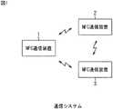
図1は、本発明を適用した通信システム(システムとは、複数の装置が論理的に結合したもの物をいい、各構成の装置が同一筐体中にあるか否かは問わない)の一実施の形態の構成例を示している。
【0020】
図1においては、通信システムは、3つのNFC通信装置1,2,3から構成されている。NFC通信装置1乃至3それぞれは、他のNFC通信装置との間で、単一の周波数の搬送波を使用した、電磁誘導による近接通信(NFC(Near Field Communication))を行うことができるようになっている。
【0021】
ここで、NFC通信装置1乃至3が使用する搬送波の周波数としては、例えば、ISM(Industrial Scientific Medical)バンドの13.56MHzなどを採用することができる。
【0022】
また、近接通信とは、通信する装置どうしの距離が、数10cm以内となって可能となる通信を意味し、通信する装置どうし(の筐体)が接触して行う通信も含まれる。
【0023】
なお、図1の通信システムは、NFC通信装置1乃至3のうちの1以上をリーダ/ライタとするとともに、他の1以上をICカードとするICカードシステムとして採用することができることは勿論、NFC通信装置1乃至3それぞれを、PDA(Personal Digital Assistant)、PC(Personal Computer)、携帯電話、腕時計、ペン等の通信システムとして採用することも可能である。即ち、NFC通信装置1乃至3は、近接通信を行う装置であり、ICカードシステムのICカードやリーダ/ライタなどに限定されるものではない。
【0024】
NFC通信装置1乃至3は、第1に、2つの通信モードによる通信が可能であることと、第2に、複数の伝送レートによるデータ伝送が可能であることとの2つの特徴を有している。
【0025】
2つの通信モードとしては、パッシブモードとアクティブモードとがある。いま、NFC通信装置1乃至3のうちの、例えば、NFC通信装置1と2の間の通信に注目すると、パッシブモードでは、上述した従来のICカードシステムと同様に、NFC通信装置1と2のうちの一方のNFC通信装置である、例えば、NFC通信装置1は、自身が発生する電磁波(に対応する搬送波)を変調することにより、他方のNFC通信装置であるNFC通信装置2にデータを送信し、NFC通信装置2は、NFC通信装置1が発生する電磁波(に対応する搬送波)を負荷変調することにより、NFC通信装置1にデータを送信する。
【0026】
一方、アクティブモードでは、NFC通信装置1と2のいずれも、自身が発生する電磁波(に対応する搬送波)を変調することにより、データを送信する。
【0027】
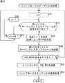
ここで、電磁誘導による近接通信を行う場合、最初に電磁波を出力して通信を開始し、いわば通信の主導権を握る装置を、イニシエータと呼ぶ。イニシエータは、通信相手にコマンドを送信し、その通信相手は、そのコマンドに対するレスポンスを返す形で、近接通信が行われるが、イニシエータからのコマンドに対するレスポンスを返す通信相手を、ターゲットと呼ぶ。
【0028】
例えば、いま、NFC通信装置1が電磁波の出力を開始して、NFC通信装置2との通信を開始したとすると、図2および図3に示すように、NFC通信装置1がイニシエータとなり、NFC通信装置2がターゲットとなる。
【0029】
そして、パッシブモードでは、図2に示すように、イニシエータであるNFC通信装置1が電磁波を出力し続け、NFC通信装置1は、自身が出力している電磁波を変調することにより、ターゲットであるNFC通信装置2に、データを送信するとともに、NFC通信装置2は、イニシエータであるNFC通信装置1が出力している電磁波を負荷変調することにより、NFC通信装置1に、データを送信する。
【0030】
一方、アクティブモードでは、図3に示すように、イニシエータであるNFC通信装置1は、自身がデータを送信する場合に、自身で電磁波の出力を開始し、その電磁波を変調することにより、ターゲットであるNFC通信装置2に、データを送信する。そして、NFC通信装置1は、データの送信終了後は、電磁波の出力を停止する。ターゲットであるNFC通信装置2も、自身がデータを送信する場合に、自身で電磁波の出力を開始し、その電磁波を変調することにより、イニシエータであるNFC通信装置1に、データを送信する。そして、NFC通信装置2は、データの送信終了後は、電磁波の出力を停止する。
【0031】
なお、NFC通信装置1乃至3が、複数の伝送レートによるデータ伝送が可能であるという第2の特徴点については、後述する。
【0032】
また、図1では、3つのNFC通信装置1乃至3によって、通信システムが構成されているが、通信システムを構成するNFC通信装置は、3つに限定されるものではなく、2または4以上であっても良い。さらに、通信システムは、NFC通信装置の他、例えば、従来のICカードシステムを構成するICカードやリーダ/ライタなどを含めて構成することも可能である。
【0033】
次に、図4は、図1のNFC通信装置1の構成例を示している。なお、図1の他のNFC通信装置2および3も、図4のNFC通信装置1と同様に構成されるため、その説明は、省略する。
【0034】
アンテナ11は、閉ループのコイルを構成しており、このコイルに流れる電流が変化することで、電磁波を出力する。また、アンテナ11としてのコイルを通る磁束が変化することで、アンテナ11に電流が流れる。
【0035】
受信部12は、アンテナ11に流れる電流を受信し、同調と検波を行い、復調部13に出力する。復調部13は、受信部12から供給される信号を復調し、デコード部14に供給する。デコード部14は、復調部13から供給される信号としての、例えばマンチェスタ符号などをデコードし、そのデコードの結果得られるデータを、データ処理部15に供給する。
【0036】
データ処理部15は、デコード部14から供給されるデータに基づき、例えば、トランスポート層などのプロトコルで行うべき処理、その他の所定の処理を行う。また、データ処理部15は、他の装置に送信すべきデータを、エンコード部16に供給する。さらに、データ処理部15は、乱数発生部24から供給される乱数を受信し、その乱数から、NFC通信装置自身を特定する情報としてのNFCID(NFC Identification)を生成する。データ処理部15は、他の装置から、後述するポーリングリクエストフレームによってNFCIDを要求された場合、乱数発生部24から供給される乱数から生成したNFCIDを、自身を特定するNFCIDとして、後述するポーリングレスポンスフレームに配置し、エンコード部16に供給する。
【0037】
エンコード部16は、データ処理部15から供給されるデータを、例えば、マンチェスタ符号などにエンコードし、選択部17に供給する。選択部17は、変調部19または負荷変調部20のうちのいずれか一方を選択し、その選択した方に、エンコード部16から供給される信号を出力する。
【0038】
ここで、選択部17は、制御部21の制御にしたがって、変調部19または負荷変調部20を選択する。制御部21は、通信モードがパッシブモードであり、NFC通信装置1がターゲットとなっている場合は、選択部17に負荷変調部20を選択させる。また、制御部21は、通信モードがアクティブモードである場合、または通信モードがパッシブモードであり、かつ、NFC通信装置1がイニシエータとなっている場合は、選択部17に変調部19を選択させる。従って、エンコード部16が出力する信号は、通信モードがパッシブモードであり、NFC通信装置1がターゲットとなっているケースでは、選択部17を介して、負荷変調部20に供給されるが、他のケースでは、選択部17を介して、変調部19に供給される。
【0039】
電磁波出力部18は、アンテナ11から、所定の単一の周波数の搬送波(の電磁波)を放射させるための電流を、アンテナ11に流す。変調部19は、電磁波出力部18がアンテナ11に流す電流としての搬送波を、選択部17から供給される信号にしたがって変調する。これにより、アンテナ11からは、データ処理部15がエンコード部16に出力したデータにしたがって搬送波を変調した電磁波が放射される。
【0040】
負荷変調部20は、外部からアンテナ11としてのコイルを見たときのインピーダンスを、選択部17から供給される信号にしたがって変化させ、これにより、負荷変調を行う。他の装置が搬送波としての電磁波を出力することにより、アンテナ11の周囲にRFフィールド(磁界)が形成されている場合、アンテナ11としてのコイルを見たときのインピーダンスが変化することにより、アンテナ11の周囲のRFフィールドも変化する。これにより、他の装置が出力している電磁波としての搬送波が、選択部17から供給される信号にしたがって変調され、データ処理部15がエンコード部16に出力したデータが、電磁波を出力している他の装置に送信される。
【0041】
ここで、変調部19および負荷変調部20における変調方式としては、例えば、振幅変調(ASK(Amplitude Shift Keying))を採用することができる。但し、変調部19および負荷変調部20における変調方式は、ASKに限定されるものではなく、PSK(Phase Shift Keying)やQAM(Quadrature Amplitude Modulation)その他を採用することが可能である。また、振幅の変調度についても8%から30%、50%、100%等数値に限定されることはなく、好適なものを選択すれば良い。
【0042】
制御部21は、NFC通信装置1を構成する各ブロックを制御する。電源部22は、NFC通信装置1を構成する各ブロックに、必要な電源を供給する。なお、図4では、制御部21がNFC通信装置1を構成する各ブロックを制御することを表す線の図示と、電源部22がNFC通信装置1を構成する各ブロックに電源を供給することを表す線の図示は、図が煩雑になるため、省略してある。
【0043】
検出部23は、受信部12と同様に、アンテナ11に流れる電流を受信し、その電流に基づいて、所定のレベル(磁束密度)以上の電磁波がアンテナ11で受信されているかどうかを検出する。
【0044】
乱数発生部24は、乱数を発生し、データ処理部15に供給する。
【0045】
ここで、上述の場合には、デコード部14およびエンコード部16において、前述のタイプCで採用されているマンチェスタ符号を処理するようにしたが、デコード部14およびエンコード部16では、マンチェスタ符号だけでなく、タイプAで採用されているモディファイドミラーや、タイプCで採用されているNRZなどの複数種類の符号の中から1つを選択して処理するようにすることが可能である。
【0046】
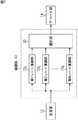
次に、図5は、図4の復調部13の構成例を示している。
【0047】
図5では、復調部13は、選択部31、2以上であるN個の復調部321乃至32N、および選択部33から構成されている。
【0048】
選択部31は、制御部21(図4)の制御にしたがい、N個の復調部321乃至32Nの中から、1つの復調部32n(n=1,2,・・・,N)を選択し、その選択した復調部32nに、受信部12が出力する信号を供給する。
【0049】
復調部32nは、第nの伝送レートで送信されてきた信号を復調し、選択部33に供給する。ここで、復調部32nと復調部32n'(n≠n’)は、異なる伝送レートで送信されてきた信号を復調する。従って、図5の復調部13は、第1乃至第NのN通りの伝送レートで送信されてくる信号を復調することができるようになっている。なお、N通りの伝送レートとしては、例えば、前述した106kbps,212kbps、さらには、より高速の424kbps,848kbpsなどを採用することができる。即ち、N通りの伝送レートには、例えば、既存のICカードシステムなどの近接通信において既に採用されている伝送レートと、それ以外の伝送レートとを含めることができる。
【0050】
選択部33は、制御部21の制御にしたがい、N個の復調部321乃至32Nの中から、1つの復調部32nを選択し、その復調部32nで得られた復調出力を、デコード部14に供給する。
【0051】
以上のように構成される復調部13では、制御部21(図4)は、例えば、選択部31に、N個の復調部321乃至32Nを順次選択させ、これにより、復調部321乃至32Nそれぞれに、受信部12から選択部31を介して供給される信号を復調させる。そして、制御部21は、例えば、受信部12から選択部31を介して供給される信号を正常に復調することができた復調部32nを認識し、その復調部32nの出力を選択するように、選択部33を制御する。選択部33は、制御部21の制御にしたがい、復調部32nを選択し、これにより、復調部32nで得られた正常な復調出力が、デコード部14に供給される。
【0052】
従って、復調部13では、N通りの伝送レートのうちの任意の伝送レートで伝送されてくる信号を復調することができる。
【0053】
なお、復調部321乃至32Nは、正常に復調を行うことができた場合のみ、復調出力を出力し、正常に復調を行うことができなかった場合には、何も出力しない(例えば、ハイインピーダンスとなる)ようにすることができる。この場合、選択部33は、復調部321乃至32Nの出力すべての論理和をとって、デコード部14に出力すれば良い。
【0054】
次に、図6は、図4の変調部19の構成例を示している。
【0055】
図6では、変調部19は、選択部41、2以上であるN個の変調部421乃至42N、および選択部43から構成されている。
【0056】
選択部41は、制御部21(図4)の制御にしたがい、N個の変調部421乃至42Nの中から、1つの変調部42n(n=1,2,・・・,N)を選択し、その選択した変調部42nに、選択部17(図4)が出力する信号を供給する。
【0057】
変調部42nは、第nの伝送レートでデータの送信が行われるように、選択部43を介して、アンテナ11に流れる電流としての搬送波を、選択部41から供給される信号にしたがって変調する。ここで、変調部42nと変調部42n'(n≠n’)は、搬送波を、異なる伝送レートで変調する。従って、図6の変調部19は、第1乃至第NのN通りの伝送レートでデータを送信することができるようになっている。なお、N通りの伝送レートとしては、例えば、図5の復調部13が復調することができるのと同一の伝送レートを採用することができる。
【0058】
選択部43は、制御部21の制御にしたがい、N個の変調部421乃至42Nの中から、選択部41が選択するのと同一の変調部42nを選択し、その変調部42nと、アンテナ11とを電気的に接続する。
【0059】
以上のように構成される変調部19では、制御部21(図4)は、例えば、選択部41に、N個の変調部421乃至42Nを順次選択させ、これにより、変調部421乃至42Nそれぞれに、選択部41から供給される信号にしたがい、選択部43を介して、アンテナ11に流れる電流としての搬送波を変調させる。
【0060】
従って、変調部19では、N通りの伝送レートのうちの任意の伝送レートでデータが送信されるように、搬送波を変調してデータを送信することができる。
【0061】
なお、図4の負荷変調部20は、例えば、図6の変調部19と同様に構成されるため、その説明は、省略する。
【0062】
以上から、NFC通信装置1乃至3では、搬送波を、N通りの伝送レートのうちのいずれかの伝送レートで送信されるデータの信号に変調するとともに、N通りの伝送レートのうちのいずれかの伝送レートで送信されてくるデータの信号を復調することができる。そして、N通りの伝送レートには、例えば、上述したように、既存のICカードシステム(FeliCa方式など)などの近接通信において既に採用されている伝送レートと、それ以外の伝送レートとを含めることができる。従って、NFC通信装置1乃至3によれば、それぞれの間では、そのN通りの伝送レートのいずれの伝送レートでも、データのやりとりを行うことができる。さらに、NFC通信装置1乃至3によれば、既存のICカードシステムを構成するICカードやリーダ/ライタとの間でも、そのICカードやリーダ/ライタが採用している伝送レートで、データのやりとりを行うことができる。
【0063】
そして、その結果、NFC通信装置1乃至3を、既存の近接通信が採用されているサービスに導入しても、ユーザが混乱等することはなく、従って、その導入を容易に行うことができる。さらに、将来登場することが予想される高速なデータレートによる近接通信が採用されるサービスにも、既存の近接通信との共存を図りながら、NFC通信装置1乃至3を、容易に導入することができる。
【0064】
また、NFC通信装置1乃至3では、従来の近接通信で採用されていたパッシブモードの他、自身が電磁波を出力することによってデータを送信するアクティブモードでのデータ伝送が可能であるため、リーダ/ライタ等の他の装置を介さなくても、データのやりとりを直接行うことができる。
【0065】
次に、図7は、図4の復調部13の他の構成例を示している。なお、図中、図5における場合と対応する部分については、同一の符号を付してあり、以下では、その説明は、適宜省略する。即ち、図7の復調部13は、選択部31が設けられていない他は、図5における場合と基本的に同様に構成されている。
【0066】
即ち、図7の実施の形態では、受信部12が出力する信号は、復調部321乃至32Nに、同時に供給され、復調部321乃至32Nでは、受信部12からの信号が同時に復調される。そして、制御部21は、例えば、受信部12からの信号を正常に復調することができた復調部32nを認識し、その復調部32nを出力するように、選択部33を制御する。選択部33は、制御部21の制御にしたがい、復調部32nを選択し、これにより、復調部32nで得られた正常な復調出力が、デコード部14に供給される。
【0067】
なお、図7の実施の形態では、復調部321乃至32Nに、常に、復調動作を行わせる必要がある。これに対して、図5の実施の形態では、復調部321乃至32Nのうちの、選択部31に選択されているものだけに復調動作を行わせ、他のものは動作を停止させておくことができる。従って、装置の消費電力を節約する観点からは、図7よりも、図5の構成の方が有利である。一方、正常な復調出力を早期に得る観点からは、図5よりも、図7の構成の方が有利である。
【0068】
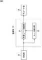
次に、図8は、図4の復調部13のさらに他の構成例を示している。
【0069】
図8では、復調部13は、可変レート復調部51とレート検出部52から構成されている。
【0070】
可変レート復調部51は、受信部12から供給される信号を、レート検出部52からの指示に応じた伝送レートの信号として復調し、その復調結果を、デコード部14に供給する。レート検出部52は、受信部12から供給される信号の伝送レートを検出し、その伝送レートの信号を復調するように、可変レート復調部51に指示する。
【0071】
以上のように構成される復調部51では、受信部12が出力する信号が、可変レート復調部51とレート検出部52に供給される。レート検出部52は、受信部12から供給される信号の伝送レートが、例えば、第1乃至第NのN通りの伝送レートのうちのいずれであるかを検出し、その伝送レートの信号を復調するように、可変レート復調部51に指示する。そして、可変レート復調部51は、受信部12から供給される信号を、レート検出部52からの指示に応じた伝送レートの信号として復調し、その復調結果を、デコード部14に供給する。
【0072】
次に、NFC通信装置1乃至3は、いずれも、最初に電磁波を出力して通信を開始するイニシエータになり得る。さらに、アクティブモードでは、NFC通信装置1乃至3は、イニシエータとなる場合でも、ターゲットとなる場合でも、自身で電磁波を出力する。
【0073】
従って、NFC通信装置1乃至3が近接している状態で、そのうちの2以上が同時に電磁波を出力した場合には、コリジョン(collision)が生じ、通信を行うことができなくなる。
【0074】
そこで、NFC通信装置1乃至3それぞれは、他の装置からの電磁波(によるRFフィールド)が存在するかどうかを検出し、存在しない場合にのみ、電磁波の出力を開始し、これにより、コリジョンを防止するようになっている。ここで、このように、他の装置からの電磁波が存在するかどうかを検出し、存在しない場合にのみ、電磁波の出力を開始する処理を、コリジョンを防止するという目的から、RFCA(RF Collision Avoidance)処理という。
【0075】
RFCA処理には、イニシエータとなろうとするNFC通信装置(図1では、NFC通信装置1乃至3のうちの1以上)が最初に行う初期RFCA処理と、アクティブモードでの通信中において、電磁波の出力を開始するNFC通信装置が、その開始をしようとするごとに行うレスポンスRFCA処理との2つがある。初期RFCA処理であっても、レスポンスRFCA処理であっても、電磁波の出力を開始する前に、他の装置による電磁波が存在するかどうかを検出し、存在しない場合にのみ、電磁波の出力を開始するという点は同一である。但し、初期RFCA処理とレスポンスRFCA処理とでは、他の装置による電磁波の存在が検出されなくなってから、電磁波の出力を開始しなければならないタイミングまでの時間等が異なる。
【0076】
そこで、まず図9を参照して、初期RFCA処理について説明する。
【0077】
図9は、初期RFCA処理によって出力が開始される電磁波を示している。なお、図9において(後述する図10も同様)、横軸は時間を表し、縦軸は、NFC通信装置が出力する電磁波のレベルを表す。
【0078】
イニシエータとなろうとするNFC通信装置は、常時、他の装置による電磁波の検出を行っており、他の装置による電磁波が、時間TIDT+n×TRFWだけ連続して検出されなかった場合、電磁波の出力を開始し、その出力から時間TIRFGだけ経過した後に、データ(コマンドを含む)の送信(Send Request)を開始する。
【0079】
ここで、時間TIDT+n×TRFWにおけるTIDTは、初期遅延時間と呼ばれ、搬送波の周波数をfcで表すこととすると、例えば、4096/fcより大の値が採用される。nは、例えば、0以上3以下の整数で、乱数を用いて生成される。TRFWは、RF待ち時間と呼ばれ、例えば、512/fcが採用される。時間TIRFGは、初期ガードタイムと呼ばれ、例えば、5msより大の値が採用される。
【0080】
なお、電磁波が検出されてはならない時間TIDT+n×TRFWに、乱数であるnを採用することにより、複数のNFC通信装置が同一のタイミングで、電磁波の出力を開始してしまう可能性の低減が図られている。
【0081】
NFC通信装置が、初期RFCA処理によって、電磁波の出力を開始した場合、そのNFC通信装置は、イニシエータとなるが、その際、通信モードとして、アクティブモードが設定されたときには、イニシエータとなったNFC通信装置は、自身のデータの送信を終了した後、電磁波の出力を停止する。一方、通信モードとして、パッシブモードが設定されたときには、イニシエータとなったNFC通信装置は、ターゲットとの通信が完全に完了するまで、初期RFCA処理によって開始した電磁波の出力を、そのまま続行する。
【0082】
次に、図10は、レスポンスRFCA処理によって出力が開始される電磁波を示している。
【0083】
アクティブモードにおいて電磁波を出力しようとするNFC通信装置は、他の装置による電磁波の検出を行い、他の装置による電磁波が、時間TADT+n×TRFWだけ連続して検出されなかった場合、電磁波の出力を開始し、その出力から時間TARFGだけ経過した後に、データの送信(Send Responsese)を開始する。
【0084】
ここで、時間TADT+n×TRFWにおけるnとTRFWは、図9の初期RFCA処理における場合と同一のものである。また、時間TADT+n×TRFWにおけるTADTは、アクティブディレイタイムと呼ばれ、例えば、768/fc以上2559/fc以下の値が採用される。時間TARFGは、アクティブガードタイムと呼ばれ、例えば、1024/fcより大の値が採用される。
【0085】
図9と図10から明らかなように、初期RFCA処理によって電磁波の出力を開始するには、少なくとも初期遅延時間TIDTの間、電磁波が存在してはならず、レスポンスRFCA処理によって電磁波の出力を開始するには、少なくともアクティブディレイタイムTADTの間、電磁波が存在してはならない。
【0086】
そして、初期遅延時間TIDTは、4096/fcより大の値であるのに対して、アクティブディレイタイムTADTは、768/fc以上2559/fc以下の値であることから、NFC通信装置がイニシエータになろうとする場合には、アクティブモードでの通信中において電磁波を出力しようとする場合よりも、電磁波が存在しない状態が長時間必要である。逆に言えば、NFC通信装置がアクティブモードでの通信中において電磁波を出力しようとする場合には、イニシエータになろうとする場合よりも、電磁波が存在しない状態になってから、それほど間をおかずに、電磁波を出力しなければならない。これは、次のような理由による。
【0087】
即ち、NFC通信装置どうしがアクティブモードで通信を行う場合、一方のNFC通信装置は、自身で電磁波を出力してデータを送信し、その後、電磁波の出力を停止する。そして、他方のNFC通信装置が電磁波の出力を開始し、データを送信する。従って、アクティブモードの通信では、いずれのNFC通信装置も、電磁波の出力を停止していることがある。このため、NFC通信装置がイニシエータになろうとする場合には、そのNFC通信装置の周囲でアクティブモードの通信が行われていないことを確認するために、イニシエータになろうとしているNFC通信装置の周囲で、他の装置が電磁波を出力していないことを、十分な時間確認する必要がある。
【0088】
これに対して、アクティブモードでは、上述したように、イニシエータが電磁波を出力することにより、ターゲットにデータを送信する。そして、ターゲットは、イニシエータが電磁波の出力を停止してから、電磁波の出力を開始することにより、イニシエータにデータを送信する。その後、イニシエータは、ターゲットが電磁波の出力を停止してから、電磁波の出力を開始することにより、イニシエータにデータを送信し、以下、同様にして、イニシエータとターゲットの間でデータがやりとりされる。
【0089】
従って、アクティブモードの通信を行っているイニシエータとターゲットの周囲に、イニシエータとなろうとするNFC通信装置が存在する場合に、アクティブモードの通信を行っているイニシエータとターゲットのうちの一方が電磁波の出力を停止してから、他方が電磁波の出力を開始するまでの時間が長いと、その間は電磁波が存在しないため、イニシエータとなろうとするNFC通信装置が、初期RFCA処理によって電磁波の出力を開始する。この場合、先に行われていたアクティブモードの通信が妨げられることになる。
【0090】
このため、アクティブモードの通信中に行われるレスポンスRFCA処理では、電磁波が存在しない状態になってから、それほど間をおかずに、電磁波を出力しなければならないようにしている。
【0091】
次に、イニシエータになろうとするNFC通信装置は、図9で説明したように、初期RFCA処理によって電磁波の出力を開始し、その後、データの送信を行う。イニシエータになろうとするNFC通信装置は、電磁波の出力を開始することで、イニシエータとなり、そのイニシエータに近接する位置に存在するNFC通信装置はターゲットとなるが、イニシエータが、ターゲットとデータのやりとりをするには、そのデータをやりとりするターゲットを特定しなければならない。このため、イニシエータは、初期RFCA処理によって電磁波の出力を開始した後に、そのイニシエータに近接する位置に存在する1以上のターゲットに対して、各ターゲットを特定する情報としてのNFCIDを要求する。そして、イニシエータに近接する位置に存在するターゲットは、イニシエータからの要求に応じて、自身を特定するNFCIDを、イニシエータに送信する。
【0092】
イニシエータは、以上のようにしてターゲットから送信されてくるNFCIDによってターゲットを特定し、その特定したターゲットとの間で、データのやりとりを行うが、イニシエータが、その周囲(近接する位置)に存在するターゲットを、そのNFCIDによって特定する処理は、SDD(Single Device Detection)処理と呼ばれる。
【0093】
ここで、SDD処理において、イニシエータは、ターゲットのNFCIDを要求するが、この要求は、イニシエータが、ポーリングリクエストフレームと呼ばれるフレームを送信することによって行われる。ターゲットは、ポーリングリクエストフレームを受信すると、例えば、自身のNFCIDを乱数によって決定し、そのNFCIDを配置したポーリングレスポンスフレームと呼ばれるフレームを送信する。イニシエータは、ターゲットから送信されてくるポーリングレスポンスフレームを受信することで、ターゲットのNFCIDを認識する。
【0094】
ところで、イニシエータが、その周囲のターゲットに対して、そのNFCIDを要求した場合、イニシエータの周囲に、複数のターゲットが存在するときには、その複数のターゲットの2以上から、同時に、NFCIDが送信されてくることがあり得る。この場合、その2以上のターゲットから送信されてくるNFCIDがコリジョンし、イニシエータは、そのコリジョンしたNFCIDを認識することができない。
【0095】
そこで、SDD処理は、NFCIDのコリジョンをなるべく避けるために、例えば、タイムスロットを用いた方法で行われる。
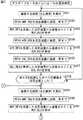
【0096】
即ち、図11は、タイムスロットを用いた方法により行われるSDD処理のシーケンスを示している。なお、図11では、イニシエータの周囲に、5つのターゲット#1,#2,#3,#4,#5が存在するものとしてある。
【0097】
SDD処理では、イニシエータがポーリングリクエストフレームを送信するが、その送信の完了後、所定の時間Tdだけおいて、所定の時間Tsの幅のタイムスロットが設けられる。なお、時間Tdは、例えば、512×64/fcとされ、タイムスロットの幅としての時間Tsは、例えば、256×64/fcとされる。また、タイムスロットは、例えば、時間的に最も先行するものから、0からのシーケンシャルな番号(整数)が付されることによって特定される。
【0098】
ここで、図11では、タイムスロット#0,#1,#2,#3の4つを示してあるが、タイムスロットは、例えば、16などの所定の数まで設けることが可能である。あるポーリングリクエストフレームに対して設けられるタイムスロットの数TSNは、イニシエータが指定し、ポーリングリクエストフレームに含められて、ターゲットに送信される。
【0099】
ターゲットは、イニシエータから送信されてくるポーリングリクエストフレームを受信し、そのポーリングリクエストフレームに配置されているタイムスロットの数TSNを認識する。さらに、ターゲットは、0以上TSN−1の範囲の整数Rを、乱数により生成し、その整数Rによって特定されるタイムスロット#Rのタイミングで、自身のNFCIDを配置したポーリングレスポンスフレームを送信する。
【0100】
以上のように、ターゲットは、ポーリングレスポンスフレームを送信するタイミングとしてのタイムスロットを、乱数により決定するので、複数のターゲットがポーリングレスポンスフレームを送信するタイミングがばらつくこととなり、これにより、複数のターゲットが送信するポーリングレスポンスフレームどうしのコリジョンを極力避けることができる。
【0101】
なお、ターゲットにおいて、ポーリングレスポンスフレームを送信するタイミングとしてのタイムスロットを、乱数により決定しても、複数のターゲットがポーリングレスポンスフレームを送信するタイムスロットが一致し、これにより、ポーリングレスポンスフレームのコリジョンが生じる場合がある。図11の実施の形態では、タイムスロット#0において、ターゲット#4のポーリングレスポンスフレームが、タイムスロット#1において、ターゲット#1と#3のポーリングレスポンスフレームが、タイムスロット#2において、ターゲット#5のポーリングレスポンスフレームが、タイムスロット#3において、ターゲット#2のポーリングレスポンスフレームが、それぞれ送信されており、ターゲット#1と#3のポーリングレスポンスフレームがコリジョンを生じている。
【0102】
この場合、イニシエータは、コリジョンを生じているターゲット#1と#3のポーリングレスポンスフレームを正常に受信することができない。そのため、イニシエータは、再度、ポーリングリクエストフレームを送信し、これにより、ターゲット#1と#3に対して、それぞれのNFCIDが配置されたポーリングレスポンスフレームの送信を要求する。以下、イニシエータにおいて、その周囲にあるターゲット#1乃至#5すべてのNFCIDを認識することができるまで、イニシエータによるポーリングリクエストフレームの送信と、ターゲットによるポーリングレスポンスフレームの送信とが繰り返し行われる。
【0103】
なお、イニシエータが、ポーリングリクエストフレームを再度送信した場合に、すべてのターゲット#1乃至#5が、ポーリングレスポンスフレームを返すこととすると、再び、ポーリングレスポンスフレームどうしがコリジョンを起こす可能性が大である。そこで、ターゲットにおいては、イニシエータからポーリングリクエストフレームを受信した後、それほど時間をおかずに、ポーリングリクエストフレームを再度受信した場合には、例えば、そのポーリングリクエストを無視するようにすることができる。但し、この場合、図11の実施の形態では、最初に送信されたポーリングリクエストフレームに対して、ポーリングレスポンスのコリジョンを生じているターゲット#1と#3については、イニシエータは、そのターゲット#1と#3のNFCIDを認識することができないので、ターゲット#1または#3との間でのデータのやりとりは、できないことになる。
【0104】
そこで、イニシエータが、ポーリングレスポンスフレームを正常に受信し、そのNFCIDを認識することができたターゲット#2,#4,#5については、後述するように、通信対象から一時的にはずし、これにより、ポーリングリクエストフレームに対する応答としてのポーリングレスポンスフレームを返さないようにすることができる。この場合、イニシエータが送信する再度のポーリングリクエストフレームに対して、ポーリングレスポンスフレームを返してくるのは、最初のポーリングリクエストフレームの送信によってNFCIDを認識することができなかったターゲット#1と#3だけとなる。従って、この場合、ポーリングレスポンスフレームどうしがコリジョンを起こす可能性を小さくしながら、ターゲット#1乃至#5すべてのNFCIDを認識することが可能となる。
【0105】
また、ここでは、ターゲットは、上述したように、ポーリングリクエストフレームを受信すると、自身のNFCIDを、乱数によって決定(生成)する。このため、異なるターゲットから、同一のNFCIDがポーリングレスポンスフレームに配置されて、イニシエータに送信されてくる場合があり得る。イニシエータが、異なるタイムスロットにおいて、同一のNFCIDが配置されたポーリングレスポンスフレームを受信した場合、イニシエータには、例えば、ポーリングレスポンスフレームどうしがコリジョンを起こした場合と同様に、ポーリングリクエストフレームを再度送信させることができる。
【0106】
なお、上述の場合には、イニシエータが、ポーリングリクエストフレームを送信した直後のタイミングを基準として、タイムスロットを設け、そのタイムスロットのタイミングで、ターゲットが、ポーリングレスポンスフレームを送信するようにしたが、イニシエータとターゲットとの間でのポーリングリクエストフレームとポーリングレスポンスフレームのやりとりは、タイムスロットを用いずに行うことが可能である。即ち、ターゲットは、ポーリングリクエストフレームを受信した場合に、任意のタイミングで、ポーリングレスポンスフレームを送信するようにすることができる。但し、この場合、タイムスロットを用いる場合に比較して、イニシエータが送信するポーリングリクエストフレームに対し、複数のターゲットが同時期にポーリングレスポンスフレームを送信するケースが増大することが予想される。そして、複数のターゲットが同時期にポーリングレスポンスフレームを送信した場合には、イニシエータは、コリジョンによりポーリングレスポンスフレームを正常受信することができないため、ポーリングリクエストフレームを再送信する必要がある。
【0107】
ここで、上述したように、NFC通信装置は、既存のICカードシステムを構成するICカードやリーダ/ライタとの間でも、そのICカードやリーダ/ライタが採用している伝送レートで、データのやりとりを行うことができる。いま、ターゲットが、例えば、既存のICカードシステムのICカードである場合、SDD処理は、例えば、次のようにして行われる。
【0108】
即ち、イニシエータは、初期RFCA処理により、電磁波の出力を開始し、ターゲットであるICカードは、その電磁波から電源を得て、処理を開始する。つまり、いまの場合、ターゲットは、既存のICカードシステムのICカードであるから、動作するための電源を、イニシエータが出力する電磁波から生成する。
【0109】
ターゲットは、電源を得て、動作可能な状態になってから、例えば、最長でも2秒以内に、ポーリングリクエストフレームを受信する準備を行い、イニシエータからポーリングリクエストフレームが送信されてくるのを待つ。
【0110】
一方、イニシエータは、ターゲットにおいてポーリングリクエストフレームを受信する準備が整ったかどうかに関係なく、ポーリングリクエストフレームを送信することができる。
【0111】
ターゲットは、イニシエータからのポーリングリクエストフレームを受信した場合、上述したように、所定のタイムスロットのタイミングで、ポーリングレスポンスフレームを、イニシエータに送信する。イニシエータは、ターゲットからのポーリングレスポンスフレームを正常受信することができた場合、上述したように、そのターゲットのNFCIDを認識する。一方、イニシエータは、ターゲットからのポーリングレスポンスフレームを正常受信することができなかった場合、ポーリングリクエストフレームを、再度送信することができる。
【0112】
なお、いまの場合、ターゲットは、既存のICカードシステムのICカードであるから、動作するための電源を、イニシエータが出力する電磁波から生成する。このため、イニシエータは、初期RFCA処理によって開始した電磁波の出力を、ターゲットとの通信が完全に終了するまで続行する。
【0113】
次に、NFC通信装置では、イニシエータがターゲットにコマンドを送信し、ターゲットが、イニシエータからのコマンドに対するレスポンスを送信する(返す)ことで、通信が行われる。
【0114】
そこで、図12は、イニシエータがターゲットに送信するコマンドと、ターゲットがイニシエータに送信するレスポンスとを示している。
【0115】
図12において、アンダーバー(_)の後にREQの文字が記述されているものは、コマンドを表し、アンダーバー(_)の後にRESの文字が記述されているものは、レスポンスを表す。図12の実施の形態では、コマンドとして、ATR_REQ,WUP_REQ,PSL_REQ,DEP_REQ,DSL_REQ,RLS_REQの6種類が用意されており、コマンドに対するレスポンスとしても、コマンドと同様に、ATR_RES,WUP_RES,PSL_RES,DEP_RES,DSL_RES,RLS_RESの6種類が用意されている。上述したように、イニシエータは、コマンド(リクエスト)をターゲットに送信し、ターゲットは、そのコマンドに対応するレスポンスをイニシエータに送信するので、コマンドは、イニシエータによって送信され、レスポンスは、ターゲットによって送信される。
【0116】
コマンドATR_REQは、イニシエータが、ターゲットに対して、自身の属性(仕様)を知らせるとともに、ターゲットの属性を要求するときに、ターゲットに送信される。ここで、イニシエータまたはターゲットの属性としては、そのイニシエータまたはターゲットが送受信することのできるデータの伝送レートなどがある。なお、コマンドATR_REQには、イニシエータの属性の他、そのイニシエータを特定するNFCIDなどが配置され、ターゲットは、コマンドATR_REQを受信することにより、イニシエータの属性とNFCIDを認識する。
【0117】
レスポンスATR_REQは、ターゲットが、コマンドATR_REQを受信した場合に、そのコマンドATR_REQに対する応答として、イニシエータに送信される。レスポンスATR_REQには、ターゲットの属性やNFCIDなどが配置される。
【0118】
なお、コマンドATR_REQやレスポンスATR_REQに配置される属性としての伝送レートの情報には、イニシエータやターゲットが送受信することのできるデータの伝送レートすべてを含めることができる。この場合、イニシエータとターゲットとの間で、コマンドATR_REQとレスポンスATR_REQのやりとりが1度行われるだけで、イニシエータは、ターゲットが送受信可能な伝送レートを認識することができ、ターゲットも、イニシエータが送受信可能な伝送レートを認識することができる。
【0119】
コマンドWUP_REQは、イニシエータが、通信するターゲットを選択するときに送信される。即ち、後述するコマンドDSL_REQを、イニシエータからターゲットに送信することにより、ターゲットを、ディセレクト(deselect)状態(イニシエータへのデータの送信(レスポンス)を禁止した状態)とすることができるが、コマンドWUP_REQは、そのディセレクト状態を解いて、ターゲットを、イニシエータへのデータの送信を可能にする状態とする場合に送信される。なお、コマンドWUP_REQには、ディセレクト状態を解くターゲットのNFCIDが配置され、コマンドWUP_REQを受信したターゲットのうち、そのコマンドWUP_REQに配置されているNFCIDによって特定されるターゲットが、ディセレクト状態を解く。
【0120】
レスポンスWUP_RESは、コマンドWUP_REQを受信したターゲットのうち、そのコマンドWUP_REQに配置されているNFCIDによって特定されるターゲットが、ディセレクト状態を解いた場合にコマンドWUP_REQに対する応答として送信される。
【0121】
コマンドPSL_REQは、イニシエータが、ターゲットとの通信に関する通信パラメータを変更するときに送信される。ここで、通信パラメータとしては、例えば、イニシエータとターゲットとの間でやりとりするデータの伝送レートなどがある。
【0122】
コマンドPSL_REQには、変更後の通信パラメータの値が配置され、イニシエータからターゲットに送信される。ターゲットは、コマンドPSL_REQを受信し、そこに配置されている通信パラメータの値にしたがって、通信パラメータを変更する。さらに、ターゲットは、コマンドPSL_REQに対するレスポンスPSL_RESを送信する。
【0123】
コマンドDEP_REQは、イニシエータが、データ(いわゆる実データ)の送受信(ターゲットとの間のデータ交換)を行うときに送信され、そこには、ターゲットに送信すべきデータが配置される。レスポンスDEP_RESは、ターゲットが、コマンドDEP_REQに対する応答として送信し、そこには、イニシエータに送信すべきデータが配置される。従って、コマンドDEP_REQによって、イニシエータからターゲットにデータが送信され、そのコマンドDEP_REQに対するレスポンスDEP_RESによって、ターゲットからイニシエータにデータが送信される。
【0124】
コマンドDSL_REQは、イニシエータが、ターゲットをディセレクト状態とするときに送信される。コマンドDSL_REQを受信したターゲットは、そのコマンドDSL_REQに対するレスポンスDSL_RESを送信してディセレクト状態となり、以後、コマンドWUP_REQ以外のコマンドには反応しなくなる(レスポンスを返さなくなる)。
【0125】
コマンドRLS_REQは、イニシエータが、ターゲットとの通信を完全に終了するときに送信される。コマンドRLS_REQを受信したターゲットは、そのコマンドRLS_REQに対するレスポンスRLS_RESを送信し、イニシエータとの通信を完全に終了する。
【0126】
ここで、コマンドDSL_REQとRLS_REQは、いずれも、ターゲットを、イニシエータとの通信の対象から解放する点で共通する。しかしながら、コマンドDSL_REQによって解放されたターゲットは、コマンドWUP_REQによって、再び、イニシエータと通信可能な状態となるが、コマンドRLS_REQによって解放されたターゲットは、イニシエータとの間で、上述したポーリングリクエストフレームとポーリングレスポンスフレームのやりとりが行われないと、イニシエータと通信可能な状態とならない。かかる点で、コマンドDSL_REQとRLS_REQは、異なる。
【0127】
なお、イニシエータは、あるターゲットにコマンドを送信する場合、例えば、ターゲットとの間でポーリングリクエストフレームとポーリングレスポンスフレームをやりとりすることにより認識した、そのターゲットのNFCIDを、コマンドに含めて送信する。一方、ターゲットは、コマンドを受信した場合、そのコマンドに含まれているNFCIDが、自身のNFCIDに一致するときに、そのコマンドに対するレスポンスをイニシエータに送信する。
【0128】
また、コマンドとレスポンスのやりとりは、例えば、トランスポート層で行うことができる。
【0129】
次に、図13のフローチャートを参照して、NFC通信装置の通信処理について説明する。
【0130】
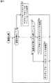
NFC通信装置は、通信を開始する場合、まず最初に、ステップS1において、他の装置による電磁波を検出したかどうかを判定する。
【0131】
ここで、NFC通信装置(図4)では、例えば、制御部21が、検出部23で検出される電磁波(NFC通信装置で用いられる電磁波と周波数帯域などが同様の電磁波)のレベルを監視しており、ステップS1では、そのレベルに基づき、他の装置による電磁波を検出したかどうかが判定される。
【0132】
ステップS1において、他の装置による電磁波が検出されなかったと判定された場合、ステップS2に進み、NFC通信装置は、その通信モードを、パッシブモードまたはアクティブモードに設定し、後述するパッシブモードのイニシエータの処理またはアクティブモードのイニシエータの処理を行う。そして、NFC通信装置は、その処理の終了後、ステップS1に戻り、以下、同様の処理を繰り返す。
【0133】
ここで、ステップS2においては、NFC通信装置の通信モードは、上述したように、パッシブモードまたはアクティブモードのうちのいずれに設定してもかまわない。但し、ターゲットが、既存のICカードシステムのICカードなどのパッシブモードのターゲットにしかなり得ない場合は、ステップS2では、NFC通信装置は、その通信モードを、パッシブモードに設定し、パッシブモードのイニシエータの処理を行う必要がある。
【0134】
一方、ステップS1において、他の装置による電磁波が検出されたと判定された場合、即ち、NFC通信装置の周辺で、他の装置による電磁波が検出された場合、ステップS3に進み、NFC通信装置は、ステップS1で検出された電磁波が検出され続けているかどうかを判定する。
【0135】
ステップS3において、電磁波が検出され続けていると判定された場合、ステップS4に進み、NFC通信装置は、その通信モードを、パッシブモードに設定し、後述するパッシブモードのターゲットの処理を行う。即ち、電磁波が検出され続けている場合というのは、例えば、NFC通信装置に近接する他の装置が、パッシブモードのイニシエータとなって、初期RFCA処理によって出力を開始した電磁波を出力し続けているケースであり、NFC通信装置は、パッシブモードのターゲットとなって処理を行う。そして、その処理の終了後は、ステップS1に戻り、以下、同様の処理が繰り返される。
【0136】
また、ステップS3において、電磁波が検出され続けていないと判定された場合、ステップS5に進み、NFC通信装置は、その通信モードを、アクティブモードに設定し、後述するアクティブモードのターゲットの処理を行う。即ち、電磁波が検出され続けていない場合というのは、例えば、NFC通信装置に近接する他の装置が、アクティブモードのイニシエータとなって、初期RFCA処理によって電磁波の出力を開始し、その後、その電磁波の出力を停止したケースであるから、NFC通信装置は、アクティブモードのターゲットとなって処理を行う。そして、その処理の終了後は、ステップS1に戻り、以下、同様の処理が繰り返される。
【0137】
次に、図14のフローチャートを参照して、NFC通信装置によるパッシブモードのイニシエータの処理について説明する。
【0138】
パッシブモードのイニシエータの処理では、まず最初に、ステップS11において、NFC通信装置は、電磁波の出力を開始する。なお、このパッシブモードのイニシエータの処理におけるステップS11は、上述の図13のステップS1において、電磁波が検出されなかった場合に行われる。即ち、NFC通信装置は、図13のステップS1において、電磁波が検出されなかった場合に、ステップS11において、電磁波の出力を開始する。従って、ステップS1およびS11の処理が、上述の初期RFCA処理に相当する。
【0139】
その後、ステップS12に進み、NFC通信装置は、伝送レートを表す変数nを、初期値としての、例えば、1にセットし、ステップS13に進む。ステップS13では、NFC通信装置は、第nの伝送レート(以下、適宜、第nレートともいう)で、ポーリングリクエストフレームを送信し、ステップS14に進む。ステップS14では、NFC通信装置は、他の装置から、第nレートで、ポーリングレスポンスフレームが送信されてきたかどうかを判定する。
【0140】
ステップS14において、他の装置から、ポーリングレスポンスフレームが送信されてきていないと判定された場合、即ち、例えば、NFC通信装置に近接する他の装置が、第nレートでの通信を行うことができず、第nレートで送信したポーリングリクエストフレームに対するポーリングレスポンスフレームが返ってこない場合、あるいは、周囲に他の装置が存在しない場合、ステップS15乃至S19をスキップして、ステップS20に進む。
【0141】
また、ステップS14において、他の装置から、第nレートで、ポーリングレスポンスフレームが送信されてきたと判定された場合、即ち、例えば、NFC通信装置に近接する他の装置が、第nレートでの通信を行うことができ、第nレートで送信したポーリングリクエストフレームに対するポーリングレスポンスフレームが返ってきた場合、ステップS15に進み、NFC通信装置は、他の装置からのポーリングレスポンスフレームを正常受信することができたかどうかを判定する。ステップS15において、他の装置からのポーリングレスポンスフレームを正常受信することができなかったと判定された場合、即ち、例えば、NFC通信装置の周囲に、複数の装置が存在し、その複数の装置からポーリングレスポンスフレームが、同一のタイムスロットで送信されてきたために、コリジョンが生じ、NFC通信装置が、ポーリングレスポンスフレームを正常受信することができなかった場合、ステップS16乃至S19をスキップして、ステップS20に進む。
【0142】
また、ステップS15において、他の装置からのポーリングレスポンスフレームを正常受信することができたと判定された場合、ステップS16に進み、NFC通信装置は、そのポーリングレスポンスフレームを返してきた他の装置をパッシブモードのターゲットとして、そのターゲットのNFCIDを、ポーリングレスポンスフレームに配置されているNFCIDによって認識し、そのNFCIDが、後述するステップS17で既に記憶したNFCIDと重複するかどうかを判定する。
【0143】
ステップS16において、他の装置からのポーリングレスポンスフレームに配置されたNFCIDが、既に記憶しているNFCIDと重複すると判定された場合、ステップS17乃至S19をスキップして、ステップS20に進む。
【0144】
また、ステップS16において、他の装置からのポーリングレスポンスフレームに配置されたNFCIDが、既に記憶しているNFCIDと重複しないと判定された場合、ステップS17に進み、NFC通信装置は、他の装置からのポーリングレスポンスフレームに配置されたNFCIDを、その、他の装置であるターゲットを特定するNFCIDとして記憶するとともに、そのターゲットが第nレートで通信可能であることを認識する。
【0145】
ここで、NFC通信装置は、ステップS17において、パッシブモードのターゲットのNFCIDと、そのターゲットが第nレートで通信可能であることを認識すると、そのターゲットとの間の伝送レートを、第nレートに(一時的に)決定し、そのターゲットとは、コマンドPSL_REQによって伝送レートが変更されない限り、第nレートで通信を行う。
【0146】
また、NFC通信装置が、ステップS17で記憶したターゲットのNFCIDは、例えば、そのターゲットとの通信が完全に終了したときに、NFC通信装置から消去される。
【0147】
その後、ステップS18に進み、NFC通信装置は、ステップS17で記憶したNFCIDのターゲット(パッシブモードのターゲット)に、コマンドDSL_REQを、第nレートで送信し、これにより、そのターゲットが、以後送信されるポーリングリクエストフレームに応答しないように、ディセレクト状態にして、ステップS19に進む。
【0148】
ステップS19では、NFC通信装置は、ステップS18で送信したコマンドDSL_REQに対して、そのコマンドDSL_REQによりディセレクト状態とされるターゲットが返してくるレスポンスDSL_RESを受信し、ステップS20に進む。
【0149】
ステップS20では、NFC通信装置は、ステップS13でポーリングリクエストフレームを、第nレートで送信してから、所定の時間が経過したかどうかを判定する。ここで、ステップS20における所定の時間は、0以上の時間とすることができる。
【0150】
ステップS20において、ステップS13でポーリングリクエストフレームを、第nレートで送信してから、まだ、所定の時間が経過していないと判定された場合、ステップS14に戻り、以下、ステップS14乃至S20の処理が繰り返される。
【0151】
ここで、ステップS14乃至S20の処理が繰り返されることにより、NFC通信装置は、図11で説明したように、異なるタイムスロットのタイミングで送信されてくるポーリングレスポンスフレームを受信することができる。
【0152】
一方、ステップS20において、ステップS13でポーリングリクエストフレームを、第nレートで送信してから、所定の時間が経過したと判定された場合、ステップS21に進み、NFC通信装置は、変数nが、その最大値であるNに等しいかどうかを判定する。ステップS21において、変数nが、最大値Nに等しくないと判定された場合、即ち、変数nが最大値N未満である場合、ステップS22に進み、NFC通信装置は、変数nを1だけインクリメントして、ステップS13に戻り、以下、ステップS13乃至S22の処理が繰り返される。
【0153】
ここで、ステップS13乃至S22の処理が繰り返されることにより、NFC通信装置は、N通りの伝送レートで、ポーリングリクエストフレームを送信するとともに、各伝送レートで返ってくるポーリングレスポンスフレームを受信する。
【0154】
一方、ステップS21において、変数nが、最大値Nに等しいと判定された場合、即ち、NFC通信装置が、N通りのN通りの伝送レートで、ポーリングリクエストフレームを送信するとともに、各伝送レートで返ってくるポーリングレスポンスフレームを受信した場合、ステップS23に進み、NFC通信装置は、ポーリングレスポンスフレームが複数の装置から同時に送信されてきたこと等に起因して、正常受信することができなかったポーリングレスポンスフレームがあったかどうかと、ステップS16で認識した他の装置のNFCIDの中に重複するものがあったかどうかを判定する。
【0155】
ステップS23において、正常受信することができなかったポーリングレスポンスフレームがあったと判定されるか、またはステップS16で認識した他の装置のNFCIDの中に重複するものがあったと判定された場合、ステップS12に戻り、以下、同様の処理が繰り返される。これにより、イニシエータが正常受信することができなかったポーリングレスポンスフレームを送信してきた装置や、重複するNFCIDを送信してきた装置などの一意の識別が可能な、いわば正常なNFCIDを取得することができなかった装置に対しては、ポーリングリクエストフレームが再送信される。
【0156】
一方、ステップS23において、正常受信することができなかったポーリングレスポンスフレームがないと判定され、かつステップS16で認識した他の装置のNFCIDの中に重複するものがないと判定された場合、ステップS24に進み、NFC通信装置は、パッシブモードのイニシエータとして、その通信処理(パッシブモードのイニシエータの通信処理)を行う。ここで、パッシブモードのイニシエータの通信処理については、後述する。
【0157】
そして、パッシブモードのイニシエータの通信処理が終了すると、NFC通信装置は、ステップS24からS25に進み、ステップS11で出力を開始した電磁波の出力を停止し、処理を終了する。
【0158】
次に、図15のフローチャートを参照して、NFC通信装置によるパッシブモードのターゲットの処理について説明する。
【0159】
パッシブモードのターゲットの処理では、まず最初に、ステップS31において、NFC通信装置は、伝送レートを表す変数nを、初期値としての、例えば、1にセットし、ステップS32に進む。ステップS32では、NFC通信装置は、パッシブモードのイニシエータとなっている他の装置から、第nレートで、ポーリングリクエストフレームが送信されてきたかどうかを判定する。
【0160】
ステップS32において、パッシブモードのイニシエータから、ポーリングリクエストフレームが送信されてきていないと判定された場合、即ち、例えば、NFC通信装置に近接する他の装置が、第nレートでの通信を行うことができず、第nレートでポーリングリクエストフレームを送信することができない場合、ステップS33に進み、NFC通信装置は、変数nが、その最大値であるNに等しいかどうかを判定する。ステップS33において、変数nが、最大値Nに等しくないと判定された場合、即ち、変数nが最大値N未満である場合、ステップS34に進み、NFC通信装置は、変数nを1だけインクリメントして、ステップS32に戻り、以下、ステップS32乃至S34の処理が繰り返される。
【0161】
また、ステップS33において、変数nが、最大値Nに等しいと判定された場合、ステップS31に戻り、以下、ステップS31乃至S34の処理が繰り返される。即ち、ここでは、パッシブモードのイニシエータから、N通りの伝送レートのうちのいずれかで送信されてくるポーリングリクエストフレームを受信することができるまで、ステップS31乃至S34の処理が繰り返される。
【0162】
そして、ステップS32において、パッシブモードのイニシエータから、ポーリングリクエストフレームが送信されてきたと判定された場合、即ち、NFC通信装置が、第nレートのポーリングリクエストフレームを正常受信した場合、ステップS35に進み、NFC通信装置は、イニシエータの間の伝送レートを第nレートに決定するとともに、乱数によって、自身のNFCIDを生成し、ステップS36に進む。ステップS36では、NFC通信装置は、自身のNFCIDを配置したポーリングレスポンスフレームを、第nレートで送信し、ステップS37に進む。
【0163】
ここで、NFC通信装置は、ステップS36でポーリングレスポンスフレームを、第nレートで送信した後は、パッシブモードのイニシエータからコマンドPSL_REQが送信されてくることによって伝送レートの変更が指示されない限り、第nレートで通信を行う。
【0164】
ステップS37では、NFC通信装置は、パッシブモードのイニシエータから、コマンドDSL_REQが送信されてきたかどうかを判定し、送信されてきていないと判定した場合、ステップS31に戻り、以下、同様の処理を繰り返す。
【0165】
即ち、パッシブモードにおいて、ターゲットが、イニシエータから送信されてきたポーリングリクエストフレームに対して、ポーリングレスポンスフレームを送信した場合には、イニシエータは、図14のステップS18で説明したように、基本的には、そのターゲットに、コマンドDSL_REQを送信する。イニシエータが、ターゲットに対して、いわば例外的にコマンドDSL_REQを送信しないのは、図14で説明したように、コリジョンによってポーリングレスポンスフレームを正常受信することができなかった場合か、またはポーリングレスポンスフレームを正常受信することができても、そのポーリングレスポンスフレームに配置されたNFCIDが、既にイニシエータが記憶しているターゲットのNFCIDと重複する場合である。即ち、イニシエータは、他のターゲットと識別することができるNFCID(正常なNFCID)を取得することができなかったターゲットに対しては、図14のステップS18において送信するコマンドDSL_REQを送信しない。
【0166】
従って、ステップS37において、コマンドDSL_REQが送信されてきていないと判定された場合は、イニシエータが、ターゲットであるNFC通信装置の正常なNFCIDを取得することができなかった場合である。このため、パッシブモードのターゲットとなっているNFC通信装置では、ステップS37からS31に戻り、上述した場合と同様の処理、即ち、イニシエータから再送信されてくるポーリングリクエストフレームを受信し、新たなNFCIDを乱数により再生成してポーリングレスポンスフレームに含めて再送信することが繰り返される。
【0167】
一方、ステップS37において、パッシブモードのイニシエータから、コマンドDSL_REQが送信されてきたと判定された場合、即ち、NFC通信装置がコマンドDSL_REQを受信した場合、ステップS38に進み、NFC通信装置は、コマンドDSL_REQに対するレスポンスDSL_REQを送信し、ディセレクト状態となって、ステップS39に進む。
【0168】
ステップS39では、NFC通信装置は、パッシブモードのターゲットとして、その通信処理(パッシブモードのターゲットの通信処理)を行い、そのパッシブモードのターゲットの通信処理が終了すると、処理を終了する。なお、パッシブモードのターゲットの通信処理については、後述する。
【0169】
次に、図16のフローチャートを参照して、NFC通信装置によるアクティブモードのイニシエータの処理について説明する。
【0170】
アクティブモードのイニシエータの処理では、ステップS51乃至S64において、図14のパッシブモードのイニシエータの処理のステップS11乃至S24における場合とそれぞれ同様の処理が行われる。但し、図14のパッシブモードのイニシエータの処理では、NFC通信装置は、その処理が終了するまで、電磁波を出力し続けるが、アクティブモードのイニシエータの処理では、NFC通信装置は、データを送信するときだけ、電磁波を出力する点が異なる。
【0171】
即ち、ステップS51において、NFC通信装置は、電磁波の出力を開始する。
なお、このアクティブモードのイニシエータの処理におけるステップS51は、上述の図13のステップS1において、電磁波が検出されなかった場合に行われる。即ち、NFC通信装置は、図13のステップS1において、電磁波が検出されなかった場合に、ステップS51において、電磁波の出力を開始する。従って、ステップS1およびS51の処理が、上述の初期RFCA処理に相当する。
【0172】
その後、ステップS52に進み、NFC通信装置は、伝送レートを表す変数nを、初期値としての、例えば、1にセットし、ステップS53に進む。ステップS53では、NFC通信装置は、第nレートで、ポーリングリクエストフレームを送信して、電磁波の出力を停止し(以下、適宜、RFオフ処理を行う、ともいう)、ステップS54に進む。
【0173】
ここで、ステップS53では、NFC通信装置は、ポーリングリクエストフレームを送信する前に、上述のアクティブRFCA処理によって電磁波の出力を開始する。但し、図16のアクティブモードのイニシエータの処理において、ステップS53の処理が最初に行われる場合は、図13のステップS1および図16のS51の処理に対応する初期RFCA処理によって、既に電磁波の出力が開始されているので、アクティブRFCA処理を行う必要はない。
【0174】
ステップS54では、NFC通信装置は、他の装置から、第nレートで、ポーリングレスポンスフレームが送信されてきたかどうかを判定する。
【0175】
ステップS54において、他の装置から、ポーリングレスポンスフレームが送信されてきていないと判定された場合、即ち、例えば、NFC通信装置に近接する他の装置が、第nレートでの通信を行うことができず、あるいは、NFC通信装置の近くに、他の装置が存在しないために、第nレートで送信したポーリングリクエストフレームに対するポーリングレスポンスフレームが返ってこない場合、ステップS55乃至S59をスキップして、ステップS60に進む。
【0176】
また、ステップS54において、他の装置から、第nレートで、ポーリングレスポンスフレームが送信されてきたと判定された場合、即ち、例えば、NFC通信装置に近接する他の装置が、第nレートでの通信を行うことができ、第nレートで送信したポーリングリクエストフレームに対するポーリングレスポンスフレームが返ってきた場合、ステップS55に進み、NFC通信装置は、他の装置からのポーリングレスポンスフレームを正常受信することができたかどうかを判定する。ステップS55において、他の装置からのポーリングレスポンスフレームを正常受信することができなかったと判定された場合、即ち、例えば、NFC通信装置の周囲に、複数の装置が存在し、その複数の装置からポーリングレスポンスフレームが、同一のタイムスロットで送信されてきたために、コリジョンが生じ、NFC通信装置が、ポーリングレスポンスフレームを正常受信することができなかった場合、ステップS56乃至S59をスキップして、ステップS60に進む。
【0177】
また、ステップS55において、他の装置からのポーリングレスポンスフレームを正常受信することができたと判定された場合、ステップS56に進み、NFC通信装置は、そのポーリングレスポンスフレームを返してきた他の装置をアクティブモードのターゲットとして、そのターゲットのNFCIDを、ポーリングレスポンスフレームに配置されているNFCIDによって認識し、そのNFCIDが、既に後述するステップS57で既に記憶したNFCIDと重複するかどうかを判定する。
【0178】
ステップS56において、他の装置からのポーリングレスポンスフレームに配置されたNFCIDが、既に記憶しているNFCIDと重複すると判定された場合、ステップS57乃至S59をスキップして、ステップS60に進む。
【0179】
また、ステップS56において、他の装置からのポーリングレスポンスフレームに配置されたNFCIDが、既に記憶しているNFCIDと重複しないと判定された場合、ステップS57に進み、NFC通信装置は、他の装置からのポーリングレスポンスフレームに配置されたNFCIDを、その、他の装置であるターゲットを特定するNFCIDとして記憶するとともに、そのターゲットが第nレートで通信可能であることを認識する。
【0180】
ここで、NFC通信装置は、ステップS57において、アクティブモードのターゲットのNFCIDと、そのターゲットが第nレートで通信可能であることを認識すると、そのターゲットとの間の伝送レートを、第nレートに決定し、そのターゲットとは、コマンドPSL_REQによって伝送レートが変更されない限り、第nレートで通信を行う。
【0181】
また、NFC通信装置が、ステップS57で記憶したターゲットのNFCIDは、例えば、そのターゲットとの通信が完全に終了したときに、NFC通信装置から消去される。
【0182】
その後、ステップS58に進み、NFC通信装置は、アクティブRFCA処理によって電磁波の出力を開始し、ステップS55で記憶したNFCIDのターゲット(アクティブモードのターゲット)に、コマンドDSL_REQを、第nレートで送信する。
これにより、そのターゲットは、以後送信されるポーリングリクエストフレーム等に応答しないディセレクト状態となる。その後、NFC通信装置は、RFオフ処理を行い、ステップS58からS59に進む。
【0183】
ステップS59では、NFC通信装置は、ステップS58で送信したコマンドDSL_REQに対して、そのコマンドDSL_REQによりディセレクト状態とされるターゲットが返してくるレスポンスDSL_RESを受信し、ステップS60に進む。
【0184】
ステップS60では、NFC通信装置は、ステップS53でポーリングリクエストフレームを、第nレートで送信してから、所定の時間が経過したかどうかを判定する。
【0185】
ステップS60において、ステップS53でポーリングリクエストフレームを、第nレートで送信してから、まだ、所定の時間が経過していないと判定された場合、ステップS54に戻り、以下、ステップS54乃至S60の処理が繰り返される。
【0186】
一方、ステップS60において、ステップS53でポーリングリクエストフレームを、第nレートで送信してから、所定の時間が経過したと判定された場合、ステップS61に進み、NFC通信装置は、変数nが、その最大値であるNに等しいかどうかを判定する。ステップS61において、変数nが、最大値Nに等しくないと判定された場合、即ち、変数nが最大値N未満である場合、ステップS62に進み、NFC通信装置は、変数nを1だけインクリメントして、ステップS53に戻り、以下、ステップS53乃至S62の処理が繰り返される。
【0187】
ここで、ステップS53乃至S62の処理が繰り返されることにより、NFC通信装置は、N通りの伝送レートで、ポーリングリクエストフレームを送信するとともに、各伝送レートで返ってくるポーリングレスポンスフレームを受信する。
【0188】
一方、ステップS61において、変数nが、最大値Nに等しいと判定された場合、即ち、NFC通信装置が、N通りのN通りの伝送レートで、ポーリングリクエストフレームを送信するとともに、各伝送レートで返ってくるポーリングレスポンスフレームを受信した場合、ステップS63に進み、NFC通信装置は、ポーリングレスポンスフレームが複数の装置から同時に送信されてきたこと等に起因して、正常受信することができなかったポーリングレスポンスフレームがあったかどうかと、ステップS56で認識した他の装置のNFCIDの中に重複するものがあったかどうかを判定する。
【0189】
ステップS63において、正常受信することができなかったポーリングレスポンスフレームがあったと判定されるか、またはステップS56で認識した他の装置のNFCIDの中に重複するものがあったと判定された場合、ステップS52に戻り、以下、同様の処理が繰り返される。これにより、イニシエータが正常受信することができなかったポーリングレスポンスフレームを送信してきた装置や、重複するNFCIDを送信してきた装置に対しては、ポーリングリクエストフレームが再送信される。
【0190】
一方、ステップS63において、正常受信することができなかったポーリングレスポンスフレームがないと判定され、かつステップS56で認識した他の装置のNFCIDの中に重複するものがないと判定された場合、ステップS64に進み、NFC通信装置は、アクティブモードのイニシエータとして、その通信処理(アクティブモードのイニシエータの通信処理)を行い、その後、処理を終了する。ここで、アクティブモードのイニシエータの通信処理については、後述する。
【0191】
次に、図17のフローチャートを参照して、NFC通信装置によるアクティブモードのターゲットの処理について説明する。
【0192】
アクティブモードのターゲットの処理では、ステップS71乃至S79において、図15のパッシブモードのターゲットの処理のステップS31乃至S39における場合とそれぞれ同様の処理が行われる。但し、図15のパッシブモードのターゲットの処理では、NFC通信装置は、パッシブモードのイニシエータが出力する電磁波を負荷変調することによってデータを送信するが、アクティブモードのターゲットの処理では、NFC通信装置は、自身で電磁波を出力してデータを送信する点が異なる。
【0193】
即ち、アクティブモードのターゲットの処理では、ステップS71乃至S75において、図15のステップS31乃至S35における場合とそれぞれ同一の処理が行われる。
【0194】
そして、ステップS75の処理後、ステップS76に進み、NFC通信装置は、アクティブRFCA処理によって電磁波の出力を開始し、自身のNFCIDを配置したポーリングレスポンスフレームを、第nレートで送信する。さらに、ステップS76では、NFC通信装置は、RFオフ処理を行い、ステップS77に進む。
【0195】
ここで、NFC通信装置は、ステップS76でポーリングレスポンスフレームを、第nレートで送信した後は、アクティブモードのイニシエータからコマンドPSL_REQが送信されてくることによって伝送レートの変更が指示されない限り、第nレートで通信を行う。
【0196】
ステップS77では、NFC通信装置は、アクティブモードのイニシエータから、コマンドDSL_REQが送信されてきたかどうかを判定し、送信されてきていないと判定した場合、ステップS71に戻り、以下、同様の処理を繰り返す。
【0197】
即ち、アクティブモードにおいて、ターゲットが、イニシエータから送信されてきたポーリングリクエストフレームに対して、ポーリングレスポンスフレームを送信した場合には、イニシエータは、図16のステップS58で説明したように、基本的には、そのターゲットに、コマンドDSL_REQを送信する。イニシエータが、ターゲットに対して、いわば例外的にコマンドDSL_REQを送信しないのは、図16で説明したように、コリジョンによってポーリングレスポンスフレームを正常受信することができなかった場合か、またはポーリングレスポンスフレームを正常受信することができても、そのポーリングレスポンスフレームに配置されたNFCIDが、既にイニシエータが記憶しているターゲットのNFCIDと重複する場合である。即ち、イニシエータは、他のターゲットと識別することができるNFCID(正常なNFCID)を取得することができなかったターゲットに対しては、図16のステップS58において送信するコマンドDSL_REQを送信しない。
【0198】
従って、ステップS77において、コマンドDSL_REQが送信されてきていないと判定された場合は、イニシエータが、ターゲットであるNFC通信装置の正常なNFCIDを取得することができなかった場合である。このため、アクティブモードのターゲットとなっているNFC通信装置では、ステップS77からS71に戻り、上述した場合と同様の処理、即ち、イニシエータから再送信されてくるポーリングリクエストフレームを受信し、新たなNFCIDを乱数により再生成してポーリングレスポンスフレームに含めて再送信することが繰り返される。
【0199】
一方、ステップS77において、パッシブモードのイニシエータから、コマンドDSL_REQが送信されてきたと判定された場合、即ち、NFC通信装置がコマンドDSL_REQを受信した場合、ステップS78に進み、NFC通信装置は、アクティブRFCA処理によって電磁波の出力を開始し、コマンドDSL_REQに対するレスポンスDSL_REQを送信する。さらに、ステップS78では、NFC通信装置は、RFオフ処理を行い、ディセレクト状態となって、ステップS79に進む。
【0200】
ステップS79では、NFC通信装置は、アクティブモードのターゲットとして、その通信処理(アクティブモードのターゲットの通信処理)を行い、そのアクティブモードのターゲットの通信処理が終了すると、処理を終了する。なお、アクティブモードのターゲットの通信処理については、後述する。
【0201】
次に、図18および図19のフローチャートを参照して、図14のステップS24におけるパッシブモードのイニシエータの通信処理について説明する。
【0202】
パッシブモードのイニシエータであるNFC通信装置は、ステップS91において、通信する装置(以下、適宜、注目装置という)を、図14のステップS15でNFCIDを記憶したターゲットの中から選択し、ステップS92に進む。ステップS92では、コマンドWUP_REQを、注目装置に送信し、これにより、図14のステップS19でコマンドDSL_REQを送信することによりディセレクト状態とした注目装置の、そのディセレクト状態を解除する(以下、適宜、ウエイクアップする、ともいう)。
【0203】
その後、NFC通信装置は、注目装置が、コマンドWUP_REQに対するレスポンスWUP_RESを送信してくるのを待って、ステップS92からS93に進み、そのレスポンスWUP_RESを受信して、ステップS94に進む。ステップS94では、NFC通信装置は、コマンドATR_REQを、注目装置に送信する。そして、NFC通信装置は、注目装置が、コマンドATR_REQに対するレスポンスATR_RESを送信してくるのを待って、ステップS94からS95に進み、そのレスポンスATR_RESを受信する。
【0204】
ここで、NFC通信装置および注目装置が、以上のようにして、属性が配置されるコマンドATR_REQとレスポンスATR_RESをやりとりすることで、NFC通信装置および注目装置は、互いに相手が通信可能な伝送レートなどを認識する。
【0205】
その後、ステップS95からS96に進み、NFC通信装置は、コマンドDSL_REQを、注目装置に送信し、注目装置を、ディセレクト状態にする。そして、NFC通信装置は、注目装置が、コマンドDSL_REQに対するレスポンスDSL_RESを送信してくるのを待って、ステップS96からS97に進み、そのレスポンスDSL_RESを受信して、ステップS98に進む。
【0206】
ステップS98では、NFC通信装置は、図14のステップS17でNFCIDを記憶したターゲットすべてを、ステップS91で注目装置として選択したかどうかを判定する。ステップS98において、NFC通信装置が、まだ、注目装置として選択していないターゲットがあると判定した場合、ステップS91に戻り、NFC通信装置は、まだ、注目装置として選択していないターゲットのうちの1つを新たに注目装置として選択し、以下、同様の処理を繰り返す。
【0207】
また、ステップS98において、NFC通信装置が、図14のステップS17でNFCIDを記憶したターゲットすべてを、ステップS91で注目装置として選択したと判定した場合、即ち、NFC通信装置が、NFCIDを記憶したターゲットすべてとの間で、コマンドATR_REQとレスポンスATR_RESをやりとりし、これにより、各ターゲットが通信可能な伝送レートなどを認識することができた場合、ステップS99に進み、NFC通信装置は、通信する装置(注目装置)を、ステップS94とS95でコマンドATR_REQとレスポンスATR_RESをやりとりしたターゲットの中から選択し、ステップS100に進む。
【0208】
ステップS100では、NFC通信装置は、コマンドWUP_REQを、注目装置に送信し、これにより、ステップS96でコマンドDSL_REQを送信することによってディセレクト状態とした注目装置をウエイクアップする。そして、NFC通信装置は、注目装置が、コマンドWUP_REQに対するレスポンスWUP_RESを送信してくるのを待って、ステップS100からS101に進み、そのレスポンスWUP_RESを受信して、図19のステップS111に進む。
【0209】
ステップS111では、NFC通信装置は、注目装置と通信を行う際の伝送レートなどの通信パラメータを変更するかどうかを判定する。
【0210】
ここで、NFC通信装置は、図18のステップS95でレスポンスATR_RESを、注目装置から受信しており、そのレスポンスATR_RESに配置された属性に基づき、注目装置が通信可能な伝送レート等の通信パラメータを認識している。NFC通信装置は、例えば、注目装置との間で、現在の伝送レートよりも高速の伝送レートで通信可能な場合、伝送レートをより高速な伝送レートに変更すべく、ステップS111において、通信パラメータを変更すると判定する。また、NFC通信装置は、例えば、注目装置との間で、現在の伝送レートよりも低速の伝送レートで通信可能であり、かつ、現在の通信環境がノイズレベルの高い環境である場合、伝送エラーを低下するために、伝送レートをより低速な伝送レートに変更すべく、ステップS111において、通信パラメータを変更すると判定する。なお、NFC通信装置と注目装置との間で、現在の伝送レートと異なる伝送レートで通信可能な場合であっても、現在の伝送レートのままで通信を続行することは可能である。
【0211】
ステップS111において、注目装置と通信を行う際の通信パラメータを変更しないと判定された場合、即ち、NFC通信装置と注目装置との間で、現在の伝送レートなどの現在の通信パラメータのままで、通信を続行する場合、ステップS112乃至S114をスキップして、ステップS115に進む。
【0212】
また、ステップS111において、注目装置と通信を行う際の通信パラメータを変更すると判定された場合、ステップS112に進み、NFC通信装置は、その変更後の通信パラメータの値を、コマンドPSL_REQに配置して、注目装置に送信する。そして、NFC通信装置は、注目装置が、コマンドPSL_REQに対するレスポンスPSL_RESを送信してくるのを待って、ステップS112からS113に進み、そのレスポンスPSL_RESを受信して、ステップS114に進む。
【0213】
ステップS114では、NFC通信装置は、注目装置との通信を行う際の伝送レートなどの通信パラメータを、ステップS112で送信したコマンドPSL_REQに配置した通信パラメータの値に変更する。NFC通信装置は、以後、注目装置との間で、再び、コマンドPSL_REQとレスポンスPSL_RESのやりとりをしない限り、ステップS114で変更された値の伝送レートなどの通信パラメータにしたがい、注目装置との通信を行う。
【0214】
なお、コマンドPSL_REQとレスポンスPSL_RESのやりとり(ネゴシエーション)によれば、伝送レート以外の、例えば、図4のエンコード部16(デコード部14)のエンコード方式や、変調部19および負荷変調部20(復調部13)の変調方式などの変更も行うことが可能である。
【0215】
その後、ステップS115に進み、NFC通信装置は、注目装置との間で送受信すべきデータがあるかどうかを判定し、ないと判定された場合、ステップS116およびS117をスキップして、ステップS118に進む。
【0216】
また、ステップS115において、注目装置との間で送受信すべきデータがあると判定された場合、ステップS116に進み、NFC通信装置は、コマンドDEP_REQを注目装置に送信する。ここで、ステップS116では、NFC通信装置は、注目装置に送信すべきデータがある場合には、そのデータを、コマンドDEP_REQに配置して送信する。
【0217】
そして、NFC通信装置は、注目装置が、コマンドDEP_REQに対するレスポンスDEP_RESを送信してくるのを待って、ステップS116からS117に進み、そのレスポンスDEP_RESを受信して、ステップS118に進む。
【0218】
以上のように、NFC通信装置と注目装置との間で、コマンドDEP_REQとレスポンスDEP_RESがやりとりされることにより、いわゆる実データの送受信が行われる。
【0219】
ステップS118では、NFC通信装置は、通信相手を変更するかどうかを判定する。ステップS118において、通信相手を変更しないと判定された場合、即ち、例えば、まだ、注目装置との間でやりとりするデータがある場合、ステップS111に戻り、以下、同様の処理が繰り返される。
【0220】
また、ステップS118において、通信相手を変更すると判定された場合、即ち、例えば、注目装置との間でやりとりするデータはないが、他の通信相手とやりとりするデータがある場合、ステップS119に進み、NFC通信装置は、コマンドDSL_REQまたはRLS_REQを注目装置に送信する。そして、NFC通信装置は、注目装置が、コマンドDSL_REQまたはRLS_REQに対するレスポンスDSL_RESまたはRLS_RESを送信してくるのを待って、ステップS119からS120に進み、そのレスポンスDSL_RESまたはRLS_RESを受信する。
【0221】
ここで、上述したように、NFC通信装置が、注目装置に対して、コマンドDSL_REQまたはRLS_REQを送信することにより、その注目装置としてのターゲットは、イニシエータとしてのNFC通信装置との通信の対象から解放される。但し、コマンドDSL_REQによって解放されたターゲットは、コマンドWUP_UPによって、再び、イニシエータと通信可能な状態となるが、コマンドRLS_REQによって解放されたターゲットは、イニシエータとの間で、上述したポーリングリクエストフレームとポーリングレスポンスフレームのやりとりが行われないと、イニシエータと通信可能な状態とならない。
【0222】
なお、あるターゲットが、イニシエータとの通信の対象から解放されるケースとしては、上述のように、イニシエータからターゲットに対して、コマンドDSL_REQまたはRLS_REQが送信される場合の他、例えば、イニシエータとターゲットとが離れすぎて、近接通信を行うことができなくなった場合がある。この場合は、コマンドRLS_REQによって解放されたターゲットと同様に、ターゲットとイニシエータとの間で、ポーリングリクエストフレームとポーリングレスポンスフレームのやりとりが行われないと、イニシエータと通信可能な状態とならない。
【0223】
ここで、以下、適宜、ターゲットとイニシエータとの間で、ポーリングリクエストフレームとポーリングレスポンスフレームのやりとりが行われないと、イニシエータと通信可能にならないターゲットの解放を、完全解放という。また、イニシエータからコマンドWUP_UPが送信されることによって、再び、イニシエータと通信可能となるターゲットの解放を、一時解放という。
【0224】
ステップS120の処理後は、ステップS121に進み、NFC通信装置は、図14のステップS17でNFCIDを記憶したターゲットすべてが完全解放されたかどうかを判定する。ステップS121において、NFCIDを記憶したターゲットすべてが、まだ完全解放されていないと判定された場合、図18のステップ99に戻り、NFC通信装置は、完全解放されていないターゲット、即ち、一時解放されているターゲットの中から、新たに注目装置を選択し、以下、同様の処理を繰り返す。
【0225】
また、ステップS121において、NFCIDを記憶したターゲットすべてが完全解放されたと判定された場合、処理を終了する。
【0226】
なお、図19のステップS116とS117において、コマンドDEP_REQとレスポンスDEP_RESがやりとりされることにより、ターゲットとイニシエータとの間で、データの送受信(データ交換)が行われるが、このコマンドDEL_REQとレスポンスDEP_RESのやりとりが、1つのトランザクションである。ステップS116とS117の処理後は、ステップS118,S111,S112,S113を介して、ステップS114に戻ることが可能であり、通信パラメータを変更することができる。従って、ターゲットとイニシエータとの間の通信に関する伝送レートなどの通信パラメータは、1つのトランザクションごとに変更することが可能である。
【0227】
また、ステップS112とS113において、イニシエータとターゲットの間で、コマンドPSL_REQとレスポンスPSL_RESをやりとりすることにより、ステップS114では、通信パラメータの1つであるイニシエータとターゲットの通信モードを変更することが可能である。従って、ターゲットとイニシエータの通信モードは、1つのトランザクションごとに変更することが可能である。なお、このことは、ターゲットとイニシエータの通信モードを、1つのトランザクションの間は、変更してはならないことを意味する。
【0228】
次に、図20のフローチャートを参照して、図15のステップS39におけるパッシブモードのターゲットの通信処理について説明する。
【0229】
パッシブモードのターゲットであるNFC通信装置は、図15のステップS37およびS38において、パッシブモードのイニシエータとの間で、コマンドDSL_REQとレスポンスDSL_RESのやりとりをしているので、ディセレクト状態となっている。
【0230】
そこで、ステップS131において、NFC通信装置は、イニシエータからコマンドWUP_REQが送信されてきたかどうかを判定し、送信されてきていないと判定した場合、ステップS131に戻り、ディセレクト状態のままとされる。
【0231】
また、ステップS131において、イニシエータからコマンドWUP_REQが送信されてきたと判定された場合、即ち、NFC通信装置がコマンドWUP_REQを受信した場合、ステップS131に進み、NFC通信装置は、コマンドWUP_REQに対するレスポンスWUP_RESを送信し、ウエイクアップして、ステップS133に進む。
【0232】
ステップS133では、NFC通信装置は、コマンドATR_REQが、イニシエータから送信されてきたかどうかを判定し、送信されてきていないと判定した場合、ステップS134をスキップして、ステップS135に進む。
【0233】
また、ステップS133において、イニシエータから、コマンドATR_REQが送信されてきたと判定された場合、即ち、NFC通信装置がコマンドATR_REQを受信した場合、ステップS135に進み、NFC通信装置は、コマンドATR_REQに対するレスポンスATR_RESを送信し、ステップS135に進む。
【0234】
ステップS135では、NFC通信装置は、コマンドDSL_REQが、イニシエータから送信されてきたかどうかを判定する。ステップS135において、イニシエータから、コマンドDSL_REQが送信されてきたと判定された場合、即ち、NFC通信装置がコマンドDSL_REQを受信した場合、ステップS136に進み、NFC通信装置は、コマンドDSL_REQに対するレスポンスDSL_RESを送信し、ステップS131に戻る。これにより、NFC通信装置は、ディセレクト状態となる。
【0235】
一方、ステップS135において、イニシエータから、コマンドDSL_REQが送信されてきていないと判定された場合、ステップS137に進み、NFC通信装置は、コマンドPSL_REQが、イニシエータから送信されてきたかどうかを判定し、送信されてきていないと判定した場合、ステップS138およびS139をスキップして、ステップS140に進む。
【0236】
また、ステップS137において、イニシエータから、コマンドPSL_REQが送信されてきたと判定された場合、即ち、NFC通信装置がコマンドPSL_REQを受信した場合、ステップS138に進み、NFC通信装置は、コマンドPSL_REQに対するレスポンスPSL_RESを送信し、ステップS139に進む。ステップS139では、NFC通信装置は、イニシエータからのコマンドPSL_REQにしたがい、その通信パラメータを変更し、ステップS140に進む。
【0237】
ステップS140では、NFC通信装置は、イニシエータから、コマンドDEP_REQが送信されてきたかどうかを判定し、送信されてきていないと判定した場合、ステップS141をスキップして、ステップS142に進む。
【0238】
また、ステップS140において、イニシエータから、コマンドDEP_REQが送信されてきたと判定された場合、即ち、NFC通信装置がコマンドDEP_REQを受信した場合、ステップS141に進み、NFC通信装置は、コマンドDEP_REQに対するレスポンスDEP_RESを送信し、ステップS142に進む。
【0239】
ステップS142では、NFC通信装置は、イニシエータから、コマンドRSL_REQが送信されてきたかどうかを判定し、送信されてきていないと判定した場合、ステップS133に戻り、以下、同様の処理が繰り返される。
【0240】
また、ステップS142において、イニシエータから、コマンドRSL_REQが送信されてきたと判定された場合、即ち、NFC通信装置がコマンドRSL_REQを受信した場合、ステップS143に進み、NFC通信装置は、コマンドRSL_REQに対するレスポンスRSL_RESを送信し、これにより、イニシエータとの通信を完全に終了して、処理を終了する。
【0241】
次に、図21および図22は、図16のステップS64におけるアクティブモードのイニシエータの通信処理の詳細を示すフローチャートである。
【0242】
なお、図18および図19で説明したパッシブモードのイニシエータの通信処理では、イニシエータが電磁波を出力し続けているが、図21および図22のアクティブモードのイニシエータの通信処理では、イニシエータが、コマンドを送信する前に、アクティブRFCA処理を行うことによって電磁波の出力を開始し、コマンドの送信の終了後に、その電磁波の出力を停止する処理(オフ処理)を行う。かかる点を除けば、図21のアクティブモードのイニシエータの通信処理では、ステップS151乃至S161と図22のステップS171乃至S181において、図18のステップステップS91乃至S101と図19のステップS111乃至S121における場合とそれぞれ同様の処理が行われるため、その説明は、省略する。
【0243】
次に、図23は、図17のステップS79におけるアクティブモードのターゲットの通信処理の詳細を示すフローチャートである。
【0244】
なお、図20で説明したパッシブモードのターゲットの通信処理では、ターゲットが、イニシエータが出力している電磁波を負荷変調することによってデータを送信するが、図23のアクティブモードのターゲットの通信処理では、ターゲットが、コマンドを送信する前に、アクティブRFCA処理を行うことによって電磁波の出力を開始し、コマンドの送信の終了後に、その電磁波の出力を停止する処理(オフ処理)を行う。かかる点を除けば、図23のアクティブモードのターゲットの通信処理では、ステップS191乃至S203において、図20のステップS131乃至S143における場合とそれぞれ同様の処理が行われるため、その説明は、省略する。
【0245】
以上のように、イニシエータにおいては、ターゲットを識別するNFCIDを要求するポーリングリクエストフレームが送信され、そのポーリングリクエストフレームに対する応答としてターゲットが送信してくるポーリングレスポンスフレームに配置されたNFCIDが取得される。そして、イニシエータにおいて、ターゲットのNFCIDを正常に取得することができなかった場合は、ポーリングリクエストフレームが再送信される。一方、ターゲットは、イニシエータからのポーリングレスポンスフレームを受信すると、自身のNFCIDを乱数により生成し、ポーリングレスポンスフレームに配置して、イニシエータに送信する。さらに、ターゲットは、イニシエータからポーリングリクエストフレームを再受信した場合、自身のNFCIDを乱数により再生成し、ポーリングレスポンスフレームに配置して、イニシエータに再送信する。
【0246】
従って、イニシエータの周囲に複数のターゲットが近接している場合に、イニシエータは、その複数のターゲットそれぞれについて、ユニークなNFCIDを取得し、そのNFCIDによって複数のターゲットそれぞれを確実に識別することができる。その結果、イニシエータが、あるNFCID宛に送信したコマンドに対して、複数のターゲットから、同時にレスポンスが送信されてくることを防止することができる。
【0247】
また、NFCIDを乱数により生成するようにしたので、固定のユニークな番号等をNFCIDとした場合に必要となる、そのNFCIDを記憶しておくためのEEPROMを装置に設ける必要がなく、装置を低コストで製造等することが可能となる。
【0248】
なお、本明細書において、NFC通信装置が行う処理を説明する処理ステップは、必ずしもフローチャートとして記載された順序に沿って時系列に処理する必要はなく、並列的あるいは個別に実行される処理(例えば、並列処理あるいはオブジェクトによる処理)も含むものである。
【0249】
また、本実施の形態では、イニシエータが、近接する位置にあるすべてのターゲットのNFCIDを取得した後、あるターゲットを注目装置として通信を行う場合に、注目装置だけをディセレクト状態からウエイクアップし、他のターゲットをディセレクト状態にしたままにしておくようにしたが、近接する位置にあるすべてのターゲットのNFCIDを取得した後は、そのすべてのターゲットをウエイクアップして通信を行うようにすることが可能である。この場合、イニシエータが送信するコマンドが、いずれのターゲットに対するものであるかは、そのコマンドに配置されるNFCIDによって認識される。即ち、イニシエータが送信したコマンドは、そのコマンドに配置されたNFCIDのターゲットが受信し、そのコマンドに対するレスポンスを、ターゲットに返すことになる。
【0250】
さらに、本実施の形態では、本発明を、複数の伝送レートでのデータの送受信が可能なNFC通信装置に適用した場合について説明したが、本発明は、その他、ある単一の伝送レートでのデータの送受信のみが可能な通信装置などにも適用可能である。さらに、本発明は、パッシブモードとアクティブモードのうちのいずれかのみによって通信を行う通信装置にも適用可能である。
【0251】
【発明の効果】
以上の如く、本発明によれば、2以上の通信相手から同時に応答が返ってくることを防止することができる。
【図面の簡単な説明】
【図1】本発明を適用した通信システムの一実施の形態の構成例を示す図である。
【図2】パッシブモードを説明する図である。
【図3】アクティブモードを説明する図である。
【図4】NFC通信装置1の構成例を示すブロック図である。
【図5】復調部13の構成例を示すブロック図である。
【図6】変調部19の構成例を示すブロック図である。
【図7】復調部13の他の構成例を示すブロック図である。
【図8】復調部13のさらに他の構成例を示すブロック図である。
【図9】初期RFCA処理を説明するタイミングチャートである。
【図10】アクティブRFCA処理を説明するタイミングチャートである。
【図11】SDD処理を説明する図である。
【図12】コマンドとレスポンスの一覧を示す図である。
【図13】NFC通信装置の処理を説明するフローチャートである。
【図14】パッシブモードのイニシエータの処理を示すフローチャートである。
【図15】パッシブモードのターゲットの処理を示すフローチャートである。
【図16】アクティブモードのイニシエータの処理を示すフローチャートである。
【図17】アクティブモードのターゲットの処理を示すフローチャートである。
【図18】パッシブモードのイニシエータの通信処理を示すフローチャートである。
【図19】パッシブモードのイニシエータの通信処理を示すフローチャートである。
【図20】パッシブモードのターゲットの通信処理を示すフローチャートである。
【図21】アクティブモードのイニシエータの通信処理を示すフローチャートである。
【図22】アクティブモードのイニシエータの通信処理を示すフローチャートである。
【図23】アクティブモードのターゲットの通信処理を示すフローチャートである。
【符号の説明】
1乃至3 NFC通信装置, 11 アンテナ, 12 受信部, 13 復調部, 14 デコード部, 15 データ処理部, 16 エンコード部, 17 選択部, 18 電磁波出力部, 19 変調部, 20 負荷変調部, 21 制御部, 22 電源部, 23 検出部, 24 乱数発生部, 31選択部, 321乃至32N 復調部, 33,41 選択部, 421乃至42N 変調部, 43 選択部, 51 可変レート復調部, 52 レート検出部[0001]
TECHNICAL FIELD OF THE INVENTION
The present invention relates to a communication device and a communication method, for example, in proximity communication or the like, capable of reliably identifying a plurality of communication partners and preventing simultaneous responses from two or more communication partners. And a communication method.
[0002]
[Prior art]
As a system for performing near field communication, for example, an IC (Integrated Curcuit) system is widely known. In an IC card system, a reader / writer generates an electromagnetic wave to form a so-called RF (Radio Frequency) field (magnetic field). When the IC card approaches the reader / writer, the IC card receives power supply by electromagnetic induction and performs data transmission with the reader / writer (for example, Patent Document 1).
[0003]
The specifications of currently implemented IC card systems include, for example, those called type A, type B, and type C.
[0004]
Type A is adopted as the Philips MIFARE method, in which data is transmitted from the reader / writer to the IC card by Miller encoding, and is transmitted from the IC card to the reader / writer. Is encoded by Manchester. In type A, 106 kbps (kilo bit per second) is adopted as a data transmission rate.
[0005]
In the type B, data is encoded by NRZ for data transmission from the reader / writer to the IC card, and data is encoded by NRZ-L for data transmission from the IC card to the reader / writer. In type B, 106 kbps is adopted as a data transmission rate.
[0006]
Type C is adopted as the FeliCa method of Sony Corporation, the present applicant, and data is encoded by Manchester for data transmission between the reader / writer and the IC card. In the type C, 212 kbps is adopted as a data transmission rate.
[0007]
[Problems to be solved by the invention]
By the way, in the IC card system, when a plurality of IC cards approach one reader / writer, the reader / writer identifies each of the plurality of IC cards, specifies a communication partner, and You need to communicate.
[0008]
As a method of identifying a plurality of IC cards, there is a method of assigning an ID as a unique identification number to the IC card, and reporting the ID from the IC card to a reader / writer.
[0009]
As described above, when a unique ID is assigned to an IC card, the ID does not overlap for any reason. However, in this case, a memory such as an EEPROM (Electrically Erasable Programmable Read Only Memory) for always storing the unique ID is required. Therefore, even when the IC card does not need the EEPROM, it is necessary to provide the EEPROM for storing the ID, and the manufacturing cost of the IC card increases.
[0010]
Therefore, there is a method of generating a random number in an IC card and temporarily using the random number as its own ID. According to this method, it is not necessary to store the ID at all times, so there is no need to provide an EEPROM for storing the ID.
[0011]
However, when a random number is used as an ID, the same random number may be used as an ID in a plurality of IC cards. In this case, when the reader / writer sends data to the ID, multiple IC cards respond at the same time, causing interference (collision), and the reader / writer normally obtains the response from the IC card. Can not do.
[0012]
The present invention has been made in view of such a situation, and it is possible to reliably identify each of a plurality of communication partners and prevent simultaneous responses from two or more communication partners. Is what you do.
[0013]
[Means for Solving the Problems]
The first communication device of the present invention transmits data requesting an ID (Identification) for identifying another device, acquires an ID transmitted by another device in response to the ID request, After obtaining the ID of the other device, data containing the ID of the other device is transmitted as data to the other device, and if the ID of the other device cannot be obtained normally, the data requesting the ID is re-read. It is characterized by transmitting.
[0014]
A first communication method of the present invention transmits data requesting an ID (Identification) for identifying another device, acquires an ID transmitted by another device in response to the ID request, After obtaining the ID of the other device, data containing the ID of the other device is transmitted as data to the other device, and if the ID of the other device cannot be obtained normally, the data requesting the ID is re-read. It is characterized by transmitting.
[0015]
When the second communication device of the present invention receives data requesting an ID (Identification) for identifying itself from another device, the second communication device generates and transmits its own ID by using a random number. When the data requesting the ID is received again, the own ID is regenerated by random number and retransmitted, and the data including the own ID among the data transmitted from other devices is used as data for itself. It is characterized by receiving.
[0016]
The second communication method of the present invention, when receiving data requesting an ID (Identification) for identifying itself from another device, generates and transmits its own ID by using a random number, When the data requesting the ID is received again, the own ID is regenerated by random number and retransmitted, and the data including the own ID among the data transmitted from other devices is used as data for itself. It is characterized by receiving.
[0017]
In the first communication device and the communication method of the present invention, data requesting an ID (Identification) for identifying another device is transmitted, and an ID transmitted by the other device in response to the ID request is acquired. You. After acquiring the ID of the other device, data including the ID of the other device is transmitted as data for the other device. On the other hand, if the ID of another device cannot be normally acquired, the data requesting the ID is retransmitted.
[0018]
In the second communication device and communication method of the present invention, when data requesting an ID (Identification) for identifying itself is received from another device, its own ID is generated by a random number and transmitted. Also, when data requesting an ID is re-received from another device, its own ID is re-generated with a random number and re-transmitted. Then, data including its own ID among the data transmitted from another device is received as data for itself.
[0019]
BEST MODE FOR CARRYING OUT THE INVENTION
FIG. 1 shows a communication system to which the present invention is applied (a system is a device in which a plurality of devices are logically combined, and it does not matter whether or not the devices of each configuration are in the same housing). 1 shows a configuration example of an embodiment.
[0020]
In FIG. 1, the communication system includes three
[0021]
Here, as the frequency of the carrier used by the
[0022]
Proximity communication means communication that can be performed when the distance between the communicating devices is within several tens of centimeters, and includes communication performed when (the housing of) the communicating devices contact each other.
[0023]
The communication system shown in FIG. 1 can be adopted as an IC card system in which one or more of the
[0024]
The
[0025]
The two communication modes include a passive mode and an active mode. Now, focusing on the communication between the
[0026]
On the other hand, in the active mode, each of the
[0027]
Here, when performing near field communication by electromagnetic induction, an apparatus that first outputs an electromagnetic wave and starts communication, so to speak, a device that takes the initiative of communication is called an initiator. The initiator transmits a command to a communication partner, and the communication partner performs near field communication in a form that returns a response to the command. A communication partner that returns a response to a command from the initiator is referred to as a target.
[0028]
For example, if the
[0029]
In the passive mode, as shown in FIG. 2, the
[0030]
On the other hand, in the active mode, as shown in FIG. 3, when the
[0031]
The second feature that the
[0032]
In FIG. 1, a communication system is configured by three
[0033]
Next, FIG. 4 shows a configuration example of the
[0034]
The
[0035]
The receiving
[0036]
The
[0037]
The
[0038]
Here, the
[0039]
The electromagnetic
[0040]
The
[0041]
Here, as a modulation method in the
[0042]
The
[0043]
The
[0044]
The
[0045]
Here, in the above case, the
[0046]
Next, FIG. 5 shows a configuration example of the
[0047]
In FIG. 5, the
[0048]
The
[0049]
Demodulation unit 32n Demodulates the signal transmitted at the n-th transmission rate and supplies the demodulated signal to the
[0050]
The
[0051]
In the
[0052]
Therefore, the
[0053]
The demodulation unit 321 To 32N Output demodulated output only when demodulation can be performed normally, and output nothing (for example, high impedance) when demodulation cannot be performed normally. Can be. In this case, the
[0054]
Next, FIG. 6 shows a configuration example of the
[0055]
In FIG. 6, the
[0056]
The
[0057]
Modulator 42n Modulates a carrier as a current flowing through the
[0058]
The
[0059]
In the
[0060]
Therefore, the
[0061]
Note that the
[0062]
As described above, in the
[0063]
As a result, even if the
[0064]
In addition, the
[0065]
Next, FIG. 7 shows another configuration example of the
[0066]
That is, in the embodiment of FIG. 7, the signal output from the receiving
[0067]
Note that, in the embodiment of FIG.1 To 32N Needs to always perform a demodulation operation. On the other hand, in the embodiment of FIG.1 To 32N Of these, only the one selected by the
[0068]
Next, FIG. 8 shows another configuration example of the
[0069]
In FIG. 8, the
[0070]
The variable
[0071]
In the
[0072]
Next, each of the
[0073]
Therefore, when two or more of the
[0074]
Therefore, each of the
[0075]
The RFCA process includes an initial RFCA process first performed by an NFC communication device (in FIG. 1, one or more of the
[0076]
Therefore, the initial RFCA process will be described first with reference to FIG.
[0077]
FIG. 9 shows an electromagnetic wave whose output is started by the initial RFCA process. In FIG. 9 (the same applies to FIG. 10 to be described later), the horizontal axis represents time, and the vertical axis represents the level of an electromagnetic wave output from the NFC communication device.
[0078]
An NFC communication device that is to become an initiator always detects electromagnetic waves by other devices, and the electromagnetic waves by other devices are transmitted for a time T.IDT + N × TRFW , The output of the electromagnetic wave is started and the time TIRFG After this, the transmission of data (including commands) (Send Request) is started.
[0079]
Here, time TIDT + N × TRFW T atIDT Is called the initial delay time, and the frequency of the carrier is fc For example, 4096 / fc Larger values are employed. n is, for example, an integer from 0 to 3 and is generated using a random number. TRFW Is called RF waiting time, for example, 512 / fc Is adopted. Time TIRFG Is called an initial guard time, and a value larger than 5 ms is adopted, for example.
[0080]
The time T during which no electromagnetic wave must be detectedIDT + N × TRFW By adopting a random number n, it is possible to reduce the possibility that a plurality of NFC communication apparatuses start outputting electromagnetic waves at the same timing.
[0081]
When the NFC communication device starts outputting an electromagnetic wave by the initial RFCA process, the NFC communication device becomes an initiator. At that time, when the active mode is set as the communication mode, the NFC communication device that becomes the initiator is used. After terminating the transmission of its own data, the device stops outputting the electromagnetic wave. On the other hand, when the passive mode is set as the communication mode, the NFC communication device serving as the initiator continues to output the electromagnetic wave started by the initial RFCA process until the communication with the target is completely completed.
[0082]
Next, FIG. 10 shows an electromagnetic wave whose output is started by the response RFCA process.
[0083]
An NFC communication device that attempts to output an electromagnetic wave in the active mode detects the electromagnetic wave by another device, and the electromagnetic wave from the other device is transmitted for a time T.ADT + N × TRFW , The output of the electromagnetic wave is started and the time TARFG After the elapse of the time, data transmission (Send Responsese) is started.
[0084]
Here, time TADT + N × TRFW N and T inRFW Are the same as those in the initial RFCA processing of FIG. Also, the time TADT + N × TRFW T atADT Is called an active delay time, for example, 768 / fc More than 2559 / fc The following values are adopted: Time TARFG Is called an active guard time, for example, 1024 / fc Larger values are employed.
[0085]
As is clear from FIGS. 9 and 10, in order to start outputting an electromagnetic wave by the initial RFCA process, at least the initial delay time TIDT During the period, the electromagnetic wave must not be present, and in order to start outputting the electromagnetic wave by the response RFCA process, at least the active delay time TADT During which no electromagnetic waves should be present.
[0086]
And the initial delay time TIDT Is 4096 / fc For a larger value, the active delay time TADT Is 768 / fc More than 2559 / fc Because of the following values, when the NFC communication device attempts to become the initiator, a state in which no electromagnetic wave is present is required for a longer time than when an electromagnetic wave is output during communication in the active mode. Conversely, when an NFC communication device attempts to output electromagnetic waves during communication in active mode, it does not have to wait as long after the electromagnetic waves have become nonexistent than when trying to become an initiator. , Must output electromagnetic waves. This is for the following reasons.
[0087]
That is, when the NFC communication devices communicate in the active mode, one of the NFC communication devices outputs an electromagnetic wave by itself to transmit data, and then stops outputting the electromagnetic wave. Then, the other NFC communication device starts outputting an electromagnetic wave and transmits data. Therefore, in the communication in the active mode, all the NFC communication apparatuses may stop outputting the electromagnetic wave. For this reason, when an NFC communication device attempts to become an initiator, the area around the NFC communication device that is about to become an initiator is checked in order to confirm that active mode communication is not being performed around that NFC communication device. Therefore, it is necessary to confirm for a sufficient time that other devices are not outputting electromagnetic waves.
[0088]
On the other hand, in the active mode, as described above, the initiator transmits data to the target by outputting an electromagnetic wave. Then, the target transmits data to the initiator by starting output of the electromagnetic wave after the initiator stops outputting the electromagnetic wave. Thereafter, the initiator transmits data to the initiator by starting output of the electromagnetic wave after the target stops outputting the electromagnetic wave, and thereafter, data is exchanged between the initiator and the target in the same manner.
[0089]
Therefore, if there is an NFC communication device that is to become the initiator around the initiator and the target that are performing the active mode communication, one of the initiator and the target that is performing the active mode communication outputs the electromagnetic wave. If the time until the other starts outputting the electromagnetic wave after stopping the communication is long, the electromagnetic wave does not exist during that time, so that the NFC communication device that intends to become the initiator starts outputting the electromagnetic wave by the initial RFCA process. In this case, the active mode communication that has been performed earlier is hindered.
[0090]
For this reason, in the response RFCA process performed during the communication in the active mode, the electromagnetic wave must be output without a long interval after the electromagnetic wave does not exist.
[0091]
Next, as described with reference to FIG. 9, the NFC communication device that intends to become an initiator starts outputting an electromagnetic wave by the initial RFCA process, and then transmits data. An NFC communication device that intends to become an initiator becomes an initiator by starting to output electromagnetic waves, and an NFC communication device located at a position close to the initiator becomes a target, but the initiator exchanges data with the target. Must identify the target with which that data is exchanged. For this reason, after starting the output of the electromagnetic wave by the initial RFCA process, the initiator requests NFCID as information for identifying each target from one or more targets existing at a position close to the initiator. Then, the target existing at a position close to the initiator transmits an NFCID specifying itself to the initiator in response to a request from the initiator.
[0092]
The initiator specifies the target by the NFCID transmitted from the target as described above, and exchanges data with the specified target. The initiator exists around (in the vicinity of) the target. The process of specifying a target by its NFCID is called an SDD (Single Device Detection) process.
[0093]
Here, in the SDD process, the initiator requests the NFCID of the target, and this request is made by the initiator transmitting a frame called a polling request frame. Upon receiving the polling request frame, the target determines, for example, its own NFCID by using a random number, and transmits a frame called a polling response frame in which the NFCID is arranged. The initiator recognizes the NFCID of the target by receiving the polling response frame transmitted from the target.
[0094]
By the way, when the initiator requests the NFCID for the surrounding targets, and when there are a plurality of targets around the initiator, the NFCID is transmitted simultaneously from two or more of the plurality of targets. It is possible. In this case, the NFCIDs transmitted from the two or more targets collide, and the initiator cannot recognize the collided NFCID.
[0095]
Therefore, the SDD process is performed by, for example, a method using a time slot in order to avoid NFCID collision as much as possible.
[0096]
That is, FIG. 11 shows a sequence of SDD processing performed by a method using time slots. In FIG. 11, it is assumed that five
[0097]
In the SDD process, the initiator transmits a polling request frame, and after completion of the transmission, a predetermined time Td Only for a predetermined time Ts Is provided. Note that time Td Is, for example, 512 × 64 / fc And the time T as the time slot widths Is, for example, 256 × 64 / fc It is said. In addition, the time slot is specified by, for example, assigning a sequential number (integer) from 0 from the temporally preceding one.
[0098]
Here, FIG. 11 shows four time slots # 0, # 1, # 2, and # 3, but it is possible to provide up to a predetermined number of time slots, such as 16, for example. The number TSN of time slots provided for a certain polling request frame is specified by the initiator, is included in the polling request frame, and is transmitted to the target.
[0099]
The target receives the polling request frame transmitted from the initiator, and recognizes the number TSN of the time slots arranged in the polling request frame. Furthermore, the target generates an integer R in the range of 0 or more and TSN-1 by a random number, and transmits a polling response frame in which its own NFCID is arranged at the timing of the time slot #R specified by the integer R.
[0100]
As described above, since the target determines the time slot as the timing for transmitting the polling response frame by using a random number, the timing for transmitting the polling response frame by a plurality of targets varies. Collisions between polling response frames to be transmitted can be minimized.
[0101]
In addition, even if the time slot as the timing for transmitting the polling response frame is determined by a random number in the target, the time slots for transmitting the polling response frame by a plurality of targets coincide with each other. May occur. In the embodiment of FIG. 11, in time slot # 0, the polling response frame of
[0102]
In this case, the initiator cannot normally receive the polling response frames of the
[0103]
If all the
[0104]
Therefore, the
[0105]
Further, here, as described above, upon receiving the polling request frame, the target determines (generates) its own NFCID by using a random number. Therefore, the same NFCID may be arranged in the polling response frame from different targets and transmitted to the initiator. When the initiator receives a polling response frame in which the same NFCID is arranged in different time slots, the initiator causes the initiator to transmit the polling request frame again, for example, as in the case where the polling response frames collide with each other. be able to.
[0106]
In the above case, the initiator sets a time slot based on the timing immediately after transmitting the polling request frame, and at the timing of the time slot, the target transmits the polling response frame. The exchange of the polling request frame and the polling response frame between the initiator and the target can be performed without using a time slot. That is, when receiving the polling request frame, the target can transmit the polling response frame at an arbitrary timing. However, in this case, it is expected that a plurality of targets transmit polling response frames at the same time in response to the polling request frame transmitted by the initiator, as compared with the case where a time slot is used. Then, when a plurality of targets transmit the polling response frame at the same time, the initiator cannot normally receive the polling response frame due to the collision, so it is necessary to retransmit the polling request frame.
[0107]
Here, as described above, the NFC communication device communicates with the IC card or reader / writer constituting the existing IC card system at the transmission rate employed by the IC card or reader / writer. Can interact. Now, when the target is, for example, an IC card of an existing IC card system, the SDD processing is performed as follows, for example.
[0108]
That is, the initiator starts outputting an electromagnetic wave by the initial RFCA process, and the target IC card obtains power from the electromagnetic wave and starts the process. That is, in this case, since the target is an IC card of an existing IC card system, a power supply for operating is generated from an electromagnetic wave output from the initiator.
[0109]
The target prepares to receive the polling request frame within, for example, at most 2 seconds after the power is obtained and becomes operable, and waits for the polling request frame to be transmitted from the initiator.
[0110]
On the other hand, the initiator can transmit a polling request frame regardless of whether the target is ready to receive the polling request frame.
[0111]
When receiving the polling request frame from the initiator, the target transmits the polling response frame to the initiator at a predetermined time slot timing as described above. When the initiator has successfully received the polling response frame from the target, the initiator recognizes the NFCID of the target as described above. On the other hand, when the initiator has not been able to normally receive the polling response frame from the target, it can retransmit the polling request frame.
[0112]
In this case, since the target is an IC card of an existing IC card system, a power supply for operating is generated from an electromagnetic wave output from the initiator. Therefore, the initiator continues to output the electromagnetic wave started by the initial RFCA process until the communication with the target is completely completed.
[0113]
Next, in the NFC communication device, communication is performed by the initiator transmitting a command to the target and the target transmitting (returning) a response to the command from the initiator.
[0114]
FIG. 12 shows a command transmitted from the initiator to the target and a response transmitted from the target to the initiator.
[0115]
In FIG. 12, the one in which REQ is described after the underbar (_) indicates a command, and the one in which RES is described after the underbar (_) indicates a response. In the embodiment of FIG. 12, six types of commands, ATR_REQ, WUP_REQ, PSL_REQ, DEP_REQ, DSL_REQ, and RLS_REQ, are prepared. Six types of DSL_RES and RLS_RES are prepared. As described above, the initiator transmits a command (request) to the target, and the target transmits a response corresponding to the command to the initiator. Therefore, the command is transmitted by the initiator, and the response is transmitted by the target. .
[0116]
The command ATR_REQ is transmitted to the target when the initiator notifies the target of its attributes (specifications) and requests the attributes of the target. Here, the attribute of the initiator or the target includes a transmission rate of data that the initiator or the target can transmit and receive. The command ATR_REQ includes, in addition to the attribute of the initiator, an NFCID or the like for specifying the initiator. The target recognizes the attribute of the initiator and the NFCID by receiving the command ATR_REQ.
[0117]
When the target receives the command ATR_REQ, the response ATR_REQ is transmitted to the initiator as a response to the command ATR_REQ. In the response ATR_REQ, a target attribute, NFCID, and the like are arranged.
[0118]
Note that the information on the transmission rate as an attribute arranged in the command ATR_REQ and the response ATR_REQ can include all transmission rates of data that can be transmitted and received by the initiator and the target. In this case, the command ATR_REQ and the response ATR_REQ are exchanged only once between the initiator and the target, and the initiator can recognize the transmission rate at which the target can transmit and receive, and the target can also transmit and receive the target. The transmission rate can be recognized.
[0119]
The command WUP_REQ is transmitted when the initiator selects a communication target. That is, by transmitting a command DSL_REQ, which will be described later, from the initiator to the target, the target can be set to a deselect state (a state in which transmission of data (response) to the initiator is prohibited). Is transmitted when the target is released from the deselect state and the target is set to a state where data transmission to the initiator is enabled. Note that the command NFCID of the target for releasing the deselect state is arranged in the command WUP_REQ, and among the targets receiving the command WUP_REQ, the target specified by the NFCID arranged in the command WUP_REQ cancels the deselect state.
[0120]
The response WUP_RES is transmitted as a response to the command WUP_REQ when the target specified by the NFCID placed in the command WUP_REQ out of the targets that have received the command WUP_REQ has released the deselect state.
[0121]
The command PSL_REQ is transmitted when the initiator changes communication parameters related to communication with the target. Here, the communication parameter includes, for example, a transmission rate of data exchanged between the initiator and the target.
[0122]
In the command PSL_REQ, the value of the communication parameter after the change is arranged, and transmitted from the initiator to the target. The target receives the command PSL_REQ, and changes the communication parameters according to the values of the communication parameters arranged therein. Further, the target transmits a response PSL_RES to the command PSL_REQ.
[0123]
The command DEP_REQ is transmitted when the initiator transmits / receives data (so-called actual data) (data exchange with the target), in which data to be transmitted to the target is arranged. The response DEP_RES is transmitted by the target as a response to the command DEP_REQ, in which data to be transmitted to the initiator is arranged. Therefore, the data is transmitted from the initiator to the target by the command DEP_REQ, and the data is transmitted from the target to the initiator by the response DEP_RES to the command DEP_REQ.
[0124]
Command DSL_REQ is transmitted when the initiator sets the target to the deselect state. The target that has received the command DSL_REQ transmits the response DSL_RES to the command DSL_REQ, enters the deselect state, and thereafter does not respond to commands other than the command WUP_REQ (response is not returned).
[0125]
The command RLS_REQ is transmitted when the initiator completes communication with the target. The target that has received the command RLS_REQ transmits a response RLS_RES to the command RLS_REQ, and completes the communication with the initiator.
[0126]
Here, the commands DSL_REQ and RLS_REQ are common in that the target is released from the target of communication with the initiator. However, the target released by the command DSL_REQ is again communicable with the initiator by the command WUP_REQ, but the target released by the command RLS_REQ is, with the initiator, the polling request frame and the polling response described above. If frames are not exchanged, it will not be possible to communicate with the initiator. In this respect, the commands DSL_REQ and RLS_REQ are different.
[0127]
In addition, when transmitting a command to a certain target, the initiator transmits, for example, the NFCID of the target recognized by exchanging a polling request frame and a polling response frame with the target, included in the command. On the other hand, when receiving the command, the target transmits a response to the command to the initiator when the NFCID included in the command matches its own NFCID.
[0128]
The exchange of commands and responses can be performed, for example, in the transport layer.
[0129]
Next, a communication process of the NFC communication device will be described with reference to a flowchart of FIG.
[0130]
When starting communication, the NFC communication device first determines in step S1 whether an electromagnetic wave from another device has been detected.
[0131]
Here, in the NFC communication device (FIG. 4), for example, the
[0132]
If it is determined in step S1 that no electromagnetic wave has been detected by another device, the process proceeds to step S2, where the NFC communication device sets the communication mode to the passive mode or the active mode, and sets the communication mode of the passive mode initiator described later. Performs processing or processing of the initiator in the active mode. Then, after the end of the process, the NFC communication apparatus returns to step S1, and thereafter repeats the same process.
[0133]
Here, in step S2, the communication mode of the NFC communication device may be set to either the passive mode or the active mode as described above. However, if the target can only be a passive mode target such as an IC card of an existing IC card system, in step S2, the NFC communication device sets the communication mode to the passive mode, and sets the initiator in the passive mode to the passive mode. Needs to be performed.
[0134]
On the other hand, when it is determined in step S1 that an electromagnetic wave by another device is detected, that is, when an electromagnetic wave by another device is detected around the NFC communication device, the process proceeds to step S3, and the NFC communication device It is determined whether or not the electromagnetic wave detected in step S1 is continuously detected.
[0135]
In step S3, when it is determined that the electromagnetic wave is continuously detected, the process proceeds to step S4, and the NFC communication device sets the communication mode to the passive mode, and performs the process of the passive mode target described later. That is, the case where the electromagnetic wave is continuously detected means that, for example, another device close to the NFC communication device has become an initiator in the passive mode and has continuously output the electromagnetic wave whose output has been started by the initial RFCA process. This is the case, and the NFC communication device performs processing with a target in the passive mode. Then, after the end of the process, the process returns to step S1, and thereafter, the same process is repeated.
[0136]
When it is determined in step S3 that the electromagnetic wave has not been continuously detected, the process proceeds to step S5, where the NFC communication device sets the communication mode to the active mode, and performs a process of an active mode target described later. . That is, the case where the electromagnetic wave is not continuously detected means that, for example, another device close to the NFC communication device becomes an initiator in the active mode, starts outputting the electromagnetic wave by the initial RFCA process, and thereafter, the electromagnetic wave is output. In this case, the NFC communication device performs processing with the target of the active mode. Then, after the end of the process, the process returns to step S1, and thereafter, the same process is repeated.
[0137]
Next, with reference to the flowchart of FIG. 14, the processing of the passive mode initiator by the NFC communication device will be described.
[0138]
In the process of the initiator in the passive mode, first, in step S11, the NFC communication device starts outputting an electromagnetic wave. Note that step S11 in the processing of the initiator in the passive mode is performed when no electromagnetic wave is detected in step S1 of FIG. 13 described above. That is, if no electromagnetic wave is detected in step S1 of FIG. 13, the NFC communication apparatus starts outputting the electromagnetic wave in step S11. Therefore, the processing of steps S1 and S11 corresponds to the above-mentioned initial RFCA processing.
[0139]
Thereafter, the process proceeds to step S12, where the NFC communication apparatus sets a variable n representing the transmission rate to, for example, 1 as an initial value, and proceeds to step S13. In step S13, the NFC communication device transmits a polling request frame at the n-th transmission rate (hereinafter, also appropriately referred to as the n-th rate), and proceeds to step S14. In step S14, the NFC communication device determines whether or not another device has transmitted a polling response frame at the n-th rate.
[0140]
If it is determined in step S14 that the polling response frame has not been transmitted from another device, that is, for example, another device close to the NFC communication device can perform communication at the n-th rate. If no polling response frame corresponding to the polling request frame transmitted at the n-th rate is returned, or if there is no other device in the vicinity, steps S15 to S19 are skipped and the process proceeds to step S20.
[0141]
Also, in step S14, when it is determined that the polling response frame has been transmitted from the other device at the n-th rate, that is, for example, another device close to the NFC communication device performs communication at the n-th rate. If the polling response frame corresponding to the polling request frame transmitted at the n-th rate is returned, the process proceeds to step S15, and the NFC communication device can normally receive the polling response frame from another device. Is determined. In step S15, when it is determined that the polling response frame from another device cannot be normally received, that is, for example, there are a plurality of devices around the NFC communication device, and polling from the plurality of devices is performed. If a collision occurs because the response frame is transmitted in the same time slot, and the NFC communication device cannot normally receive the polling response frame, skip steps S16 to S19 and proceed to step S20. move on.
[0142]
If it is determined in step S15 that a polling response frame from another device has been successfully received, the process proceeds to step S16, where the NFC communication device passively transmits the other device that has returned the polling response frame. As the mode target, the NFCID of the target is recognized by the NFCID arranged in the polling response frame, and it is determined whether or not the NFCID overlaps with the NFCID already stored in step S17 described later.
[0143]
If it is determined in step S16 that the NFCID arranged in the polling response frame from another device overlaps with the already stored NFCID, steps S17 to S19 are skipped, and the process proceeds to step S20.
[0144]
Also, in step S16, when it is determined that the NFCID arranged in the polling response frame from another device does not overlap with the NFCID already stored, the process proceeds to step S17, and the NFC communication device transmits The NFCID arranged in the polling response frame is stored as the NFCID specifying the target, which is another device, and it is recognized that the target can communicate at the n-th rate.
[0145]
Here, in step S17, the NFC communication device recognizes that the NFCID of the passive mode target and the target can communicate at the n-th rate, and sets the transmission rate between the target and the target to the n-th rate. Decide (temporarily), and communicate with the target at the n-th rate unless the transmission rate is changed by the command PSL_REQ.
[0146]
Further, the NFCID of the target stored by the NFC communication device in step S17 is deleted from the NFC communication device when the communication with the target is completely completed, for example.
[0147]
Thereafter, the process proceeds to step S18, where the NFC communication apparatus transmits the command DSL_REQ at the n-th rate to the NFCID target (passive mode target) stored in step S17, whereby the target is transmitted thereafter. The process goes to the deselect state so as not to respond to the polling request frame, and proceeds to step S19.
[0148]
In step S19, in response to the command DSL_REQ transmitted in step S18, the NFC communication apparatus receives a response DSL_RES returned by the target deselected by the command DSL_REQ, and proceeds to step S20.
[0149]
In step S20, the NFC communication device determines whether a predetermined time has elapsed after transmitting the polling request frame at the n-th rate in step S13. Here, the predetermined time in step S20 can be 0 or more.
[0150]
In step S20, if it is determined that the predetermined time has not yet elapsed since the polling request frame was transmitted at the n-th rate in step S13, the process returns to step S14, and the processing in steps S14 to S20 is performed. Is repeated.
[0151]
Here, by repeating the processing of steps S14 to S20, the NFC communication apparatus can receive the polling response frame transmitted at the timing of the different time slot as described with reference to FIG.
[0152]
On the other hand, in step S20, when it is determined that the predetermined time has elapsed since the polling request frame was transmitted at the n-th rate in step S13, the process proceeds to step S21, and the NFC communication device determines that the variable n It is determined whether it is equal to the maximum value N. If it is determined in step S21 that the variable n is not equal to the maximum value N, that is, if the variable n is smaller than the maximum value N, the process proceeds to step S22, and the NFC communication device increments the variable n by one. Then, the process returns to step S13, and thereafter, the processes of steps S13 to S22 are repeated.
[0153]
Here, by repeating the processing of steps S13 to S22, the NFC communication apparatus transmits the polling request frames at N transmission rates and receives the polling response frames returned at each transmission rate.
[0154]
On the other hand, when it is determined in step S21 that the variable n is equal to the maximum value N, that is, the NFC communication apparatus transmits the polling request frame at N transmission rates and N transmission rates, and at each transmission rate. When the returned polling response frame is received, the process proceeds to step S23, and the NFC communication device determines that the polling that could not be normally received due to the simultaneous transmission of the polling response frame from a plurality of devices. It is determined whether or not there is a response frame and whether or not there is a duplicate among the NFCIDs of the other devices recognized in step S16.
[0155]
If it is determined in step S23 that there was a polling response frame that could not be received normally, or if it was determined that there was a duplicate among the NFCIDs of the other devices recognized in step S16, step S12 And the same processing is repeated thereafter. As a result, a device that has transmitted a polling response frame that the initiator has not been able to normally receive or a device that has transmitted a duplicate NFCID can be uniquely identified, that is, a normal NFCID can be obtained. The polling request frame is retransmitted to the device that did not exist.
[0156]
On the other hand, if it is determined in step S23 that there is no polling response frame that could not be normally received, and if it is determined that there is no duplicate among the NFCIDs of the other devices recognized in step S16, the process proceeds to step S24. The NFC communication device performs the communication process (communication process of the passive mode initiator) as the passive mode initiator. Here, the communication process of the initiator in the passive mode will be described later.
[0157]
Then, when the communication process of the initiator in the passive mode ends, the NFC communication device proceeds from step S24 to S25, stops the output of the electromagnetic wave whose output has been started in step S11, and ends the process.
[0158]
Next, with reference to the flowchart of FIG. 15, the processing of the target in the passive mode by the NFC communication device will be described.
[0159]
In the processing of the target in the passive mode, first, in step S31, the NFC communication apparatus sets a variable n representing a transmission rate to, for example, 1 as an initial value, and proceeds to step S32. In step S32, the NFC communication device determines whether the polling request frame has been transmitted at the n-th rate from another device that is the initiator in the passive mode.
[0160]
In step S32, when it is determined that the polling request frame has not been transmitted from the passive mode initiator, that is, for example, another device close to the NFC communication device performs communication at the n-th rate. If the polling request frame cannot be transmitted at the n-th rate, the process proceeds to step S33, and the NFC communication apparatus determines whether the variable n is equal to the maximum value N. If it is determined in step S33 that the variable n is not equal to the maximum value N, that is, if the variable n is smaller than the maximum value N, the process proceeds to step S34, and the NFC communication device increments the variable n by 1. Then, the process returns to step S32, and thereafter, the processes of steps S32 to S34 are repeated.
[0161]
If it is determined in step S33 that the variable n is equal to the maximum value N, the process returns to step S31, and the processes in steps S31 to S34 are repeated. That is, here, the processes of steps S31 to S34 are repeated until a polling request frame transmitted at any one of the N transmission rates can be received from the initiator in the passive mode.
[0162]
If it is determined in step S32 that the polling request frame has been transmitted from the passive mode initiator, that is, if the NFC communication device has normally received the n-th rate polling request frame, the process proceeds to step S35. The NFC communication device determines the transmission rate between the initiators as the n-th rate, generates its own NFCID using a random number, and proceeds to step S36. In step S36, the NFC communication device transmits a polling response frame in which its own NFCID is arranged at the n-th rate, and proceeds to step S37.
[0163]
Here, after transmitting the polling response frame at the n-th rate in step S36, the NFC communication apparatus transmits the polling response frame at the n-th rate unless a command PSL_REQ is transmitted from the passive mode initiator to instruct the change of the transmission rate. Communicate at a rate.
[0164]
In step S37, the NFC communication device determines whether or not the command DSL_REQ has been transmitted from the initiator in the passive mode. If it is determined that the command DSL_REQ has not been transmitted, the process returns to step S31, and the same process is repeated.
[0165]
That is, in the passive mode, when the target transmits a polling response frame in response to the polling request frame transmitted from the initiator, the initiator basically transmits the polling response frame as described in step S18 of FIG. And sends the command DSL_REQ to the target. The initiator does not send the command DSL_REQ exceptionally to the target, as described in FIG. 14, when the polling response frame cannot be normally received due to the collision, or when the polling response frame is not transmitted. This is a case where the NFCID arranged in the polling response frame overlaps with the NFCID of the target already stored in the initiator even if the NFCID can be normally received. That is, the initiator does not transmit the command DSL_REQ to be transmitted in step S18 of FIG. 14 to a target for which an NFCID (normal NFCID) that can be identified from another target cannot be obtained.
[0166]
Therefore, when it is determined in step S37 that the command DSL_REQ has not been transmitted, it means that the initiator has not been able to acquire the normal NFCID of the target NFC communication device. For this reason, the NFC communication device that is the target of the passive mode returns from step S37 to S31, and performs the same processing as described above, that is, receives the polling request frame retransmitted from the initiator and generates a new NFCID. Is repeated by using a random number, included in the polling response frame, and retransmitted.
[0167]
On the other hand, if it is determined in step S37 that the command DSL_REQ has been transmitted from the initiator in the passive mode, that is, if the NFC communication device has received the command DSL_REQ, the process proceeds to step S38, and the NFC communication device responds to the command DSL_REQ. A response DSL_REQ is transmitted, the state is deselected, and the process proceeds to step S39.
[0168]
In step S39, the NFC communication device performs the communication process (communication process of the passive mode target) as a passive mode target, and ends the process when the passive mode target communication process ends. The communication process of the passive mode target will be described later.
[0169]
Next, with reference to the flowchart in FIG. 16, the processing of the initiator in the active mode by the NFC communication device will be described.
[0170]
In the processing of the initiator in the active mode, in steps S51 to S64, the same processing as the processing in the steps S11 to S24 of the processing in the passive mode initiator of FIG. 14 is performed. However, in the processing of the initiator in the passive mode in FIG. 14, the NFC communication apparatus continues to output the electromagnetic wave until the processing ends, but in the processing of the initiator in the active mode, the NFC communication apparatus transmits the electromagnetic wave. The only difference is that it outputs electromagnetic waves.
[0171]
That is, in step S51, the NFC communication device starts outputting an electromagnetic wave.
Note that step S51 in the processing of the initiator in the active mode is performed when no electromagnetic wave is detected in step S1 of FIG. 13 described above. That is, if no electromagnetic wave is detected in step S1 of FIG. 13, the NFC communication device starts outputting the electromagnetic wave in step S51. Therefore, the processing of steps S1 and S51 corresponds to the above-mentioned initial RFCA processing.
[0172]
Thereafter, the process proceeds to step S52, where the NFC communication device sets a variable n representing the transmission rate to, for example, 1 as an initial value, and proceeds to step S53. In step S53, the NFC communication device transmits a polling request frame at the n-th rate, stops outputting electromagnetic waves (hereinafter, also referred to as appropriately performing RF off processing), and proceeds to step S54.
[0173]
Here, in step S53, before transmitting the polling request frame, the NFC communication apparatus starts outputting an electromagnetic wave by the above-described active RFCA processing. However, when the processing of step S53 is performed first in the processing of the initiator in the active mode of FIG. 16, the output of the electromagnetic wave is already performed by the initial RFCA processing corresponding to the processing of step S1 of FIG. 13 and S51 of FIG. Since it has been started, there is no need to perform active RFCA processing.
[0174]
In step S54, the NFC communication device determines whether or not another device has transmitted a polling response frame at the n-th rate.
[0175]
In step S54, when it is determined that the polling response frame has not been transmitted from another device, that is, for example, another device close to the NFC communication device can perform communication at the n-th rate. If no polling response frame corresponding to the polling request frame transmitted at the n-th rate is returned because no other device exists near the NFC communication device, the process skips steps S55 to S59 and proceeds to step S60. Proceed to.
[0176]
Also, in step S54, when it is determined that the polling response frame has been transmitted from the other device at the n-th rate, that is, for example, another device close to the NFC communication device performs communication at the n-th rate. If the polling response frame corresponding to the polling request frame transmitted at the n-th rate is returned, the process proceeds to step S55, and the NFC communication device can normally receive the polling response frame from another device. Is determined. In step S55, when it is determined that the polling response frame from another device has not been normally received, that is, for example, there are a plurality of devices around the NFC communication device, and polling from the plurality of devices is performed. When the response frame is transmitted in the same time slot, a collision occurs and the NFC communication device cannot normally receive the polling response frame, skip steps S56 to S59 and proceed to step S60. move on.
[0177]
If it is determined in step S55 that a polling response frame from another device has been successfully received, the process proceeds to step S56, and the NFC communication device activates the other device that has returned the polling response frame. As the mode target, the NFCID of the target is recognized by the NFCID arranged in the polling response frame, and it is determined whether or not the NFCID overlaps with the NFCID already stored in step S57 described later.
[0178]
If it is determined in step S56 that the NFCID arranged in the polling response frame from another device overlaps with the NFCID already stored, the process skips steps S57 to S59 and proceeds to step S60.
[0179]
Also, in step S56, when it is determined that the NFCID arranged in the polling response frame from another device does not overlap with the already stored NFCID, the process proceeds to step S57, and the NFC communication device transmits The NFCID arranged in the polling response frame is stored as the NFCID specifying the target, which is another device, and it is recognized that the target can communicate at the n-th rate.
[0180]
Here, when the NFC communication apparatus recognizes in step S57 that the NFCID of the target in the active mode and the target can communicate at the n-th rate, the NFC communication apparatus changes the transmission rate between the target and the target to the n-th rate. Determined and communicates with the target at the n-th rate unless the transmission rate is changed by the command PSL_REQ.
[0181]
Further, the NFCID of the target stored by the NFC communication device in step S57 is deleted from the NFC communication device, for example, when the communication with the target is completely completed.
[0182]
Thereafter, the process proceeds to step S58, where the NFC communication apparatus starts outputting the electromagnetic wave by the active RFCA process, and transmits the command DSL_REQ at the n-th rate to the NFCID target (active mode target) stored in step S55.
As a result, the target enters a deselect state in which it does not respond to a polling request frame or the like transmitted thereafter. Thereafter, the NFC communication device performs an RF off process, and proceeds from step S58 to S59.
[0183]
In step S59, in response to the command DSL_REQ transmitted in step S58, the NFC communication device receives a response DSL_RES returned by the target deselected by the command DSL_REQ, and proceeds to step S60.
[0184]
In step S60, the NFC communication device determines whether a predetermined time has elapsed after transmitting the polling request frame at the n-th rate in step S53.
[0185]
In step S60, when it is determined that the predetermined time has not yet elapsed since the polling request frame was transmitted at the n-th rate in step S53, the process returns to step S54, and the processes in steps S54 to S60 are performed. Is repeated.
[0186]
On the other hand, in step S60, when it is determined that the predetermined time has elapsed since the polling request frame was transmitted at the n-th rate in step S53, the process proceeds to step S61, and the NFC communication apparatus sets the variable n to It is determined whether it is equal to the maximum value N. If it is determined in step S61 that the variable n is not equal to the maximum value N, that is, if the variable n is less than the maximum value N, the process proceeds to step S62, and the NFC communication device increments the variable n by one. Then, the process returns to step S53, and thereafter, the processes of steps S53 to S62 are repeated.
[0187]
Here, by repeating the processing of steps S53 to S62, the NFC communication apparatus transmits the polling request frames at N transmission rates and receives the polling response frames returned at each transmission rate.
[0188]
On the other hand, when it is determined in step S61 that the variable n is equal to the maximum value N, that is, the NFC communication apparatus transmits the polling request frame at N transmission rates and N transmission rates and at each transmission rate. When the returned polling response frame is received, the process proceeds to step S63, and the NFC communication device determines that the polling that could not be normally received due to the simultaneous transmission of the polling response frame from a plurality of devices. It is determined whether or not there is a response frame and whether or not there is a duplicate among the NFCIDs of the other devices recognized in step S56.
[0189]
If it is determined in step S63 that there was a polling response frame that could not be received normally, or if it was determined that there was a duplicate among the NFCIDs of the other devices recognized in step S56, step S52 And the same processing is repeated thereafter. As a result, a polling request frame is retransmitted to a device that has transmitted a polling response frame that the initiator has not been able to normally receive or a device that has transmitted an overlapping NFCID.
[0190]
On the other hand, if it is determined in step S63 that there is no polling response frame for which normal reception was not possible, and if it is determined that there is no duplicate NFCID in another device recognized in step S56, the process proceeds to step S64. The NFC communication device performs the communication process (communication process of the initiator in the active mode) as the initiator in the active mode, and thereafter ends the process. Here, the communication process of the initiator in the active mode will be described later.
[0191]
Next, the processing of the target in the active mode by the NFC communication device will be described with reference to the flowchart in FIG.
[0192]
In the processing of the target in the active mode, in steps S71 to S79, the same processing as the processing in the steps S31 to S39 of the processing of the passive mode target in FIG. 15 is performed. However, in the processing of the target in the passive mode in FIG. 15, the NFC communication device transmits data by load-modulating the electromagnetic wave output from the initiator in the passive mode. , In that it outputs electromagnetic waves and transmits data.
[0193]
That is, in the processing of the target in the active mode, in steps S71 to S75, the same processing as that in steps S31 to S35 of FIG. 15 is performed.
[0194]
Then, after the process of step S75, the process proceeds to step S76, where the NFC communication device starts outputting the electromagnetic wave by the active RFCA process, and transmits the polling response frame in which its own NFCID is arranged at the n-th rate. Further, in step S76, the NFC communication device performs an RF off process, and proceeds to step S77.
[0195]
Here, after transmitting the polling response frame at the n-th rate in step S76, the NFC communication apparatus transmits the polling response frame at the n-th rate unless a command PSL_REQ is transmitted from the initiator in the active mode to instruct the change of the transmission rate. Communicate at a rate.
[0196]
In step S77, the NFC communication device determines whether or not the command DSL_REQ has been transmitted from the initiator in the active mode. If it is determined that the command DSL_REQ has not been transmitted, the process returns to step S71, and the same process is repeated.
[0197]
That is, in the active mode, when the target transmits a polling response frame in response to the polling request frame transmitted from the initiator, the initiator basically operates as described in step S58 of FIG. And sends the command DSL_REQ to the target. The reason why the initiator does not transmit the command DSL_REQ to the target as an exception, as described with reference to FIG. 16, is when the polling response frame cannot be normally received due to the collision, or when the polling response frame is not transmitted. This is a case where the NFCID arranged in the polling response frame overlaps with the NFCID of the target already stored in the initiator even if the NFCID can be normally received. That is, the initiator does not transmit the command DSL_REQ to be transmitted in step S58 in FIG. 16 to the target for which the NFCID (normal NFCID) that can be identified from other targets cannot be obtained.
[0198]
Therefore, when it is determined in step S77 that the command DSL_REQ has not been transmitted, it means that the initiator has not been able to acquire the normal NFCID of the target NFC communication device. For this reason, the NFC communication device that is the target of the active mode returns from step S77 to S71, and performs the same processing as described above, that is, receives the polling request frame retransmitted from the initiator and adds a new NFCID. Is repeated by using a random number, included in the polling response frame, and retransmitted.
[0199]
On the other hand, if it is determined in step S77 that the command DSL_REQ has been transmitted from the initiator in the passive mode, that is, if the NFC communication device has received the command DSL_REQ, the process proceeds to step S78, and the NFC communication device performs the active RFCA processing. To start outputting electromagnetic waves, and transmit a response DSL_REQ to the command DSL_REQ. Further, in step S78, the NFC communication device performs an RF off process, enters a deselect state, and proceeds to step S79.
[0200]
In step S79, the NFC communication device performs the communication process (communication process of the target in the active mode) as the target of the active mode, and ends the process when the communication process of the target in the active mode ends. The communication process of the target in the active mode will be described later.
[0201]
Next, the communication processing of the initiator in the passive mode in step S24 of FIG. 14 will be described with reference to the flowcharts of FIGS.
[0202]
In step S91, the NFC communication device that is the initiator in the passive mode selects a device to be communicated (hereinafter, appropriately referred to as a device of interest) from the targets that have stored the NFCID in step S15 in FIG. 14, and proceeds to step S92. . In step S92, the command WUP_REQ is transmitted to the device of interest, thereby releasing the deselected state of the device of interest that has been deselected by transmitting the command DSL_REQ in step S19 of FIG. 14 (hereinafter, appropriately Wake up).
[0203]
Thereafter, the NFC communication device waits for the device of interest to transmit a response WUP_RES to the command WUP_REQ, proceeds from step S92 to S93, receives the response WUP_RES, and proceeds to step S94. In step S94, the NFC communication device transmits the command ATR_REQ to the device of interest. Then, the NFC communication apparatus waits for the attention apparatus to transmit a response ATR_RES to the command ATR_REQ, proceeds from step S94 to S95, and receives the response ATR_RES.
[0204]
Here, the NFC communication device and the device of interest exchange the command ATR_REQ and the response ATR_RES in which the attributes are arranged as described above, so that the NFC communication device and the device of interest can communicate with each other, such as a transmission rate at which the other party can communicate with each other. Recognize.
[0205]
Thereafter, the process proceeds from step S95 to S96, where the NFC communication device transmits the command DSL_REQ to the device of interest, and sets the device of interest to the deselect state. Then, the NFC communication device waits for the device of interest to transmit a response DSL_RES to the command DSL_REQ, proceeds from step S96 to S97, receives the response DSL_RES, and proceeds to step S98.
[0206]
In step S98, the NFC communication device determines whether or not all the targets storing the NFCID in step S17 in FIG. 14 have been selected as the devices of interest in step S91. In step S98, if the NFC communication device determines that there is a target that has not yet been selected as the device of interest, the process returns to step S91, and the NFC communication device returns one of the targets that has not yet been selected as the device of interest. One is newly selected as the device of interest, and the same processing is repeated thereafter.
[0207]
Further, in step S98, when the NFC communication apparatus determines that all the targets that have stored the NFCID in step S17 of FIG. 14 have been selected as the target apparatus in step S91, that is, the NFC communication apparatus determines that the target in which the NFCID is stored A command ATR_REQ and a response ATR_RES are exchanged with all the devices. When the target A can recognize a transmission rate or the like at which each target can communicate, the process proceeds to step S99, and the NFC communication device communicates with the communication device ( The target device is selected from the targets that exchanged the command ATR_REQ and the response ATR_RES in steps S94 and S95, and the process proceeds to step S100.
[0208]
In step S100, the NFC communication device transmits the command WUP_REQ to the device of interest, and thereby wakes up the device of interest in the deselected state by transmitting the command DSL_REQ in step S96. Then, the NFC communication apparatus waits for the attention apparatus to transmit a response WUP_RES to the command WUP_REQ, proceeds from step S100 to S101, receives the response WUP_RES, and proceeds to step S111 in FIG.
[0209]
In step S111, the NFC communication device determines whether to change a communication parameter such as a transmission rate when communicating with the device of interest.
[0210]
Here, the NFC communication device has received the response ATR_RES from the device of interest in step S95 of FIG. 18, and based on the attribute arranged in the response ATR_RES, sets the communication parameter such as the transmission rate at which the device of interest can communicate, such as a transmission rate. It has recognized. For example, when the NFC communication device can communicate with the device of interest at a transmission rate higher than the current transmission rate, the communication parameter is changed in step S111 to change the transmission rate to a higher transmission rate. Judge to change. Further, for example, the NFC communication device can communicate with the device of interest at a transmission rate lower than the current transmission rate, and if the current communication environment is an environment with a high noise level, a transmission error occurs. In order to reduce the transmission rate, it is determined in step S111 that the communication parameters are changed in order to change the transmission rate to a lower transmission rate. Note that, even if the NFC communication device and the device of interest can communicate at a transmission rate different from the current transmission rate, it is possible to continue communication at the current transmission rate.
[0211]
In step S111, when it is determined that the communication parameters for performing communication with the device of interest are not changed, that is, between the NFC communication device and the device of interest, the current communication parameters such as the current transmission rate remain unchanged. If the communication is to be continued, the process skips steps S112 to S114 and proceeds to step S115.
[0212]
Also, in step S111, when it is determined that the communication parameter for performing communication with the device of interest is changed, the process proceeds to step S112, and the NFC communication device places the value of the changed communication parameter in the command PSL_REQ. , To the device of interest. Then, the NFC communication apparatus waits for the attention apparatus to transmit a response PSL_RES to the command PSL_REQ, proceeds from step S112 to S113, receives the response PSL_RES, and proceeds to step S114.
[0213]
In step S114, the NFC communication device changes a communication parameter such as a transmission rate when performing communication with the device of interest to a value of the communication parameter arranged in the command PSL_REQ transmitted in step S112. The NFC communication device thereafter communicates with the device of interest according to the communication parameters such as the transmission rate of the value changed in step S114 unless the command PSL_REQ and the response PSL_RES are exchanged again with the device of interest. Do.
[0214]
According to the exchange (negotiation) of the command PSL_REQ and the response PSL_RES, for example, the encoding method of the encoding unit 16 (the decoding unit 14) shown in FIG. 4 and the
[0215]
Thereafter, the process proceeds to step S115, in which the NFC communication device determines whether there is data to be transmitted / received to / from the device of interest, and if not, skips steps S116 and S117 and proceeds to step S118. .
[0216]
If it is determined in step S115 that there is data to be transmitted / received to / from the device of interest, the process proceeds to step S116, and the NFC communication device transmits a command DEP_REQ to the device of interest. Here, in step S116, if there is data to be transmitted to the target device, the NFC communication device arranges the data in the command DEP_REQ and transmits the data.
[0219]
Then, the NFC communication device waits for the device of interest to transmit a response DEP_RES to the command DEP_REQ, proceeds from step S116 to S117, receives the response DEP_RES, and proceeds to step S118.
[0218]
As described above, the real data is transmitted and received by exchanging the command DEP_REQ and the response DEP_RES between the NFC communication device and the device of interest.
[0219]
In step S118, the NFC communication device determines whether to change the communication partner. In step S118, when it is determined that the communication partner is not changed, that is, for example, when there is still data to be exchanged with the device of interest, the process returns to step S111, and the same processing is repeated.
[0220]
If it is determined in step S118 that the communication partner is to be changed, that is, if there is no data to be exchanged with the device of interest but there is data to be exchanged with another communication partner, the process proceeds to step S119. The NFC communication device transmits the command DSL_REQ or RLS_REQ to the device of interest. Then, the NFC communication device waits for the device of interest to transmit a response DSL_RES or RLS_RES to the command DSL_REQ or RLS_REQ, and proceeds from step S119 to S120 to receive the response DSL_RES or RLS_RES.
[0221]
Here, as described above, the NFC communication device transmits the command DSL_REQ or RLS_REQ to the device of interest, thereby releasing the target as the device of interest from the target of communication with the NFC communication device as the initiator. Is done. However, the target released by the command DSL_REQ is again enabled to communicate with the initiator by the command WUP_UP, but the target released by the command RLS_REQ is the polling request frame and the polling response described above between the initiator and the initiator. If frames are not exchanged, it will not be possible to communicate with the initiator.
[0222]
In addition, as a case where a certain target is released from a target of communication with the initiator, as described above, in addition to a case where the command DSL_REQ or RLS_REQ is transmitted from the initiator to the target, for example, the initiator and the target May be too far apart to perform close proximity communication. In this case, similarly to the target released by the command RLS_REQ, unless the polling request frame and the polling response frame are exchanged between the target and the initiator, the target does not enter a state in which communication with the initiator is possible.
[0223]
Hereafter, release of a target that cannot communicate with the initiator unless a polling request frame and a polling response frame are exchanged between the target and the initiator is referred to as complete release. In addition, releasing a target that can communicate with the initiator again by transmitting the command WUP_UP from the initiator is referred to as temporary release.
[0224]
After the process in step S120, the process proceeds to step S121, and the NFC communication device determines whether all the targets storing the NFCID in step S17 in FIG. 14 have been completely released. If it is determined in step S121 that all the targets that have stored the NFCIDs have not been completely released, the process returns to step 99 in FIG. 18, and the NFC communication apparatus returns the targets that have not been completely released, that is, temporarily releases the targets. The target device is newly selected from the existing targets, and the same processing is repeated thereafter.
[0225]
If it is determined in step S121 that all targets storing the NFCID have been completely released, the process ends.
[0226]
In steps S116 and S117 in FIG. 19, the command DEP_REQ and the response DEP_RES are exchanged to perform data transmission / reception (data exchange) between the target and the initiator. An exchange is one transaction. After the processing of steps S116 and S117, it is possible to return to step S114 via steps S118, S111, S112, and S113, and to change the communication parameters. Therefore, communication parameters such as a transmission rate for communication between the target and the initiator can be changed for each transaction.
[0227]
Also, by exchanging the command PSL_REQ and the response PSL_RES between the initiator and the target in steps S112 and S113, it is possible to change the communication mode between the initiator and the target, which is one of the communication parameters, in step S114. is there. Therefore, the communication mode between the target and the initiator can be changed for each transaction. This means that the communication mode between the target and the initiator must not be changed during one transaction.
[0228]
Next, with reference to the flowchart of FIG. 20, the communication process of the target in the passive mode in step S39 of FIG. 15 will be described.
[0229]
The NFC communication device that is the target in the passive mode exchanges the command DSL_REQ and the response DSL_RES with the initiator in the passive mode in steps S37 and S38 in FIG. 15, and thus is in the deselected state.
[0230]
Therefore, in step S131, the NFC communication device determines whether or not the command WUP_REQ has been transmitted from the initiator. If it is determined that the command has not been transmitted, the process returns to step S131 and remains in the deselected state.
[0231]
If it is determined in step S131 that the command WUP_REQ has been transmitted from the initiator, that is, if the NFC communication device has received the command WUP_REQ, the process proceeds to step S131, and the NFC communication device transmits a response WUP_RES to the command WUP_REQ. Then, it wakes up and proceeds to step S133.
[0232]
In step S133, the NFC communication device determines whether or not the command ATR_REQ has been transmitted from the initiator. If it is determined that the command ATR_REQ has not been transmitted, the process skips step S134 and proceeds to step S135.
[0233]
Also, in step S133, when it is determined that the command ATR_REQ has been transmitted from the initiator, that is, when the NFC communication device receives the command ATR_REQ, the process proceeds to step S135, and the NFC communication device transmits a response ATR_RES to the command ATR_REQ. Then, the process proceeds to step S135.
[0234]
In step S135, the NFC communication device determines whether the command DSL_REQ has been transmitted from the initiator. In step S135, when it is determined that the command DSL_REQ has been transmitted from the initiator, that is, when the NFC communication device receives the command DSL_REQ, the process proceeds to step S136, and the NFC communication device transmits a response DSL_RES to the command DSL_REQ. Then, the process returns to step S131. As a result, the NFC communication device enters the deselect state.
[0235]
On the other hand, when it is determined in step S135 that the command DSL_REQ has not been transmitted from the initiator, the process proceeds to step S137, and the NFC communication apparatus determines whether the command PSL_REQ has been transmitted from the initiator, and transmits the command PSL_REQ. If it is determined that no request has been received, steps S138 and S139 are skipped, and the process proceeds to step S140.
[0236]
If it is determined in step S137 that the command PSL_REQ has been transmitted from the initiator, that is, if the NFC communication device receives the command PSL_REQ, the process proceeds to step S138, and the NFC communication device transmits a response PSL_RES to the command PSL_REQ. Then, the process proceeds to step S139. In step S139, the NFC communication device changes its communication parameters according to the command PSL_REQ from the initiator, and proceeds to step S140.
[0237]
In step S140, the NFC communication device determines whether or not the command DEP_REQ has been transmitted from the initiator. If it is determined that the command DEP_REQ has not been transmitted, the NFC communication device skips step S141 and proceeds to step S142.
[0238]
If it is determined in step S140 that the command DEP_REQ has been transmitted from the initiator, that is, if the NFC communication device has received the command DEP_REQ, the process proceeds to step S141, and the NFC communication device transmits a response DEP_RES to the command DEP_REQ. Then, the process proceeds to step S142.
[0239]
In step S142, the NFC communication device determines whether or not the command RSL_REQ has been transmitted from the initiator. If it is determined that the command RSL_REQ has not been transmitted, the process returns to step S133, and the same processing is repeated.
[0240]
If it is determined in step S142 that the command RSL_REQ has been transmitted from the initiator, that is, if the NFC communication device has received the command RSL_REQ, the process proceeds to step S143, and the NFC communication device transmits a response RSL_RES to the command RSL_REQ. Then, the communication with the initiator is completely terminated, and the process is terminated.
[0241]
Next, FIG. 21 and FIG. 22 are flowcharts showing the details of the communication processing of the initiator in the active mode in step S64 of FIG.
[0242]
In the communication processing of the initiator in the passive mode described with reference to FIGS. 18 and 19, the initiator continues to output the electromagnetic wave. However, in the communication processing of the initiator in the active mode in FIGS. 21 and 22, the initiator transmits a command. Before the transmission, the output of the electromagnetic wave is started by performing the active RFCA process, and after the transmission of the command is completed, the process of stopping the output of the electromagnetic wave (off process) is performed. Except for this point, in the communication processing of the initiator in the active mode in FIG. 21, the processing in steps S151 to S161 and steps S171 to S181 in FIG. 22 is performed, and the processing in steps S91 to S101 in FIG. Since the same processing is performed, the description thereof is omitted.
[0243]
Next, FIG. 23 is a flowchart showing details of the communication processing of the target in the active mode in step S79 in FIG.
[0244]
In the communication processing of the target in the passive mode described with reference to FIG. 20, the target transmits data by load-modulating the electromagnetic wave output from the initiator. In the communication processing of the target in the active mode in FIG. Before transmitting the command, the target starts the output of the electromagnetic wave by performing the active RFCA process, and performs the process of stopping the output of the electromagnetic wave (off process) after the transmission of the command is completed. Except for this point, in the communication processing of the target in the active mode in FIG. 23, the same processing as in steps S131 to S143 in FIG. 20 is performed in steps S191 to S203, and a description thereof will be omitted.
[0245]
As described above, the polling request frame requesting the NFCID for identifying the target is transmitted to the initiator, and the NFCID arranged in the polling response frame transmitted from the target is obtained as a response to the polling request frame. Then, when the initiator cannot normally acquire the NFCID of the target, the polling request frame is retransmitted. On the other hand, when receiving the polling response frame from the initiator, the target generates its own NFCID with a random number, arranges the NFCID in the polling response frame, and transmits the polling response frame to the initiator. Further, when the target receives the polling request frame again from the initiator, the target regenerates its own NFCID with a random number, arranges the NFCID in the polling response frame, and retransmits the polling request frame to the initiator.
[0246]
Therefore, when a plurality of targets are close to the initiator, the initiator can acquire a unique NFCID for each of the plurality of targets, and can reliably identify each of the plurality of targets based on the NFCID. As a result, it is possible to prevent a response from being transmitted from a plurality of targets simultaneously to a command transmitted to a certain NFCID by the initiator.
[0247]
In addition, since the NFCID is generated by random numbers, it is not necessary to provide an EEPROM for storing the NFCID, which is necessary when a fixed unique number or the like is used as the NFCID. It becomes possible to manufacture at a low cost.
[0248]
In the present specification, processing steps for explaining processing performed by an NFC communication apparatus do not necessarily need to be processed in chronological order in the order described as a flowchart, and processing performed in parallel or individually (for example, , Parallel processing or processing by an object).
[0249]
Further, in the present embodiment, after the initiator obtains the NFCIDs of all targets located in the vicinity of the target, when performing communication with a certain target as a target device, only the target device wakes up from the deselect state, Other targets are left deselected, but after obtaining the NFCIDs of all nearby targets, wake up all the targets and start communication. Is possible. In this case, to which target the command transmitted by the initiator is recognized is identified by the NFCID arranged in the command. That is, the command transmitted by the initiator is received by the NFCID target allocated to the command, and a response to the command is returned to the target.
[0250]
Furthermore, in the present embodiment, the case where the present invention is applied to an NFC communication device capable of transmitting and receiving data at a plurality of transmission rates has been described. The present invention is also applicable to a communication device that can only transmit and receive data. Further, the present invention is also applicable to a communication device that performs communication only in one of the passive mode and the active mode.
[0251]
【The invention's effect】
As described above, according to the present invention, it is possible to prevent a response from being returned from two or more communication partners at the same time.
[Brief description of the drawings]
FIG. 1 is a diagram illustrating a configuration example of an embodiment of a communication system to which the present invention has been applied.
FIG. 2 is a diagram illustrating a passive mode.
FIG. 3 is a diagram illustrating an active mode.
FIG. 4 is a block diagram illustrating a configuration example of an
FIG. 5 is a block diagram illustrating a configuration example of a
FIG. 6 is a block diagram illustrating a configuration example of a
FIG. 7 is a block diagram illustrating another configuration example of the
FIG. 8 is a block diagram showing still another configuration example of the
FIG. 9 is a timing chart illustrating an initial RFCA process.
FIG. 10 is a timing chart illustrating an active RFCA process.
FIG. 11 is a diagram illustrating SDD processing.
FIG. 12 is a diagram showing a list of commands and responses.
FIG. 13 is a flowchart illustrating a process of the NFC communication device.
FIG. 14 is a flowchart illustrating processing of an initiator in a passive mode.
FIG. 15 is a flowchart illustrating processing of a target in a passive mode.
FIG. 16 is a flowchart illustrating processing of an initiator in an active mode.
FIG. 17 is a flowchart showing processing of a target in the active mode.
FIG. 18 is a flowchart illustrating communication processing of an initiator in a passive mode.
FIG. 19 is a flowchart showing a communication process of an initiator in a passive mode.
FIG. 20 is a flowchart illustrating communication processing of a target in a passive mode.
FIG. 21 is a flowchart showing communication processing of an initiator in an active mode.
FIG. 22 is a flowchart illustrating a communication process of an initiator in an active mode.
FIG. 23 is a flowchart showing communication processing of a target in an active mode.
[Explanation of symbols]
1 to 3 NFC communication device, 11 antenna, 12 reception unit, 13 demodulation unit, 14 decoding unit, 15 data processing unit, 16 encoding unit, 17 selection unit, 18 electromagnetic wave output unit, 19 modulation unit, 20 load modulation unit, 21 Control section, 22 power supply section, 23 detection section, 24 random number generation section, 31 selection section, 321 To 32N Demodulation unit, 33, 41 selection unit, 421 To 42N Modulator, 43 selector, 51 variable rate demodulator, 52 rate detector
Claims (7)
Translated fromJapanese電磁波を発生することにより、RF(Radio Frequency)フィールドを形成する電磁波発生手段と、
電磁波を変調することにより、複数の伝送レートのうちのいずれかの伝送レートでデータを送信する変調手段と、
電磁波を復調することにより、複数の伝送レートのうちのいずれかの伝送レートで、他の装置から送信されてくるデータを取得する復調手段と
を備え、
前記他の装置を識別するID(Identification)を要求するデータを送信し、
前記IDの要求に応じて前記他の装置が送信してくる前記IDを取得し、
前記他の装置のIDの取得後は、前記他の装置に対するデータとして、前記他の装置のIDを含むデータを送信し、
前記他の装置のIDを正常に取得することができなかった場合、前記IDを要求するデータを再送信する
ことを特徴とする通信装置。In a communication device that transmits and receives data by electromagnetic waves,
Electromagnetic wave generating means for forming an RF (Radio Frequency) field by generating electromagnetic waves,
Modulating means for transmitting data at any one of a plurality of transmission rates by modulating an electromagnetic wave,
By demodulating the electromagnetic waves, at any one of a plurality of transmission rates, demodulation means for obtaining data transmitted from another device,
Transmit data requesting an ID (Identification) for identifying the other device,
Acquiring the ID transmitted by the other device in response to the request for the ID,
After acquiring the ID of the other device, as data for the other device, transmit data including the ID of the other device,
A communication device for retransmitting data requesting the ID when the ID of the other device cannot be normally acquired.
ことを特徴とする請求項1に記載の通信装置。When the IDs are transmitted simultaneously from a plurality of the other devices, or when IDs transmitted from the plurality of the other devices are duplicated, the data requesting the ID is retransmitted, The communication device according to claim 1, wherein
電磁波を発生することにより、RF(Radio Frequency)フィールドを形成する電磁波発生ステップと、
電磁波を変調することにより、複数の伝送レートのうちのいずれかの伝送レートでデータを送信する変調ステップと、
電磁波を復調することにより、複数の伝送レートのうちのいずれかの伝送レートで、他の装置から送信されてくるデータを取得する復調ステップと
を備え、
前記他の装置を識別するID(Identification)を要求するデータを送信し、
前記IDの要求に応じて前記他の装置が送信してくる前記IDを取得し、
前記他の装置のIDの取得後は、前記他の装置に対するデータとして、前記他の装置のIDを含むデータを送信し、
前記他の装置のIDを正常に取得することができなかった場合、前記IDを要求するデータを再送信する
ことを特徴とする通信方法。In a communication method of transmitting and receiving data by electromagnetic waves,
An electromagnetic wave generation step of forming an RF (Radio Frequency) field by generating an electromagnetic wave,
A modulation step of transmitting data at any one of a plurality of transmission rates by modulating the electromagnetic wave;
By demodulating the electromagnetic waves, at any one of a plurality of transmission rates, a demodulation step of obtaining data transmitted from another device,
Transmit data requesting an ID (Identification) for identifying the other device,
Acquiring the ID transmitted by the other device in response to the request for the ID,
After acquiring the ID of the other device, as data for the other device, transmit data including the ID of the other device,
A communication method characterized by retransmitting data requesting the ID when the ID of the other device cannot be normally acquired.
電磁波を変調することにより、複数の伝送レートのうちのいずれかの伝送レートでデータを送信する変調手段と、
電磁波を復調することにより、複数の伝送レートのうちのいずれかの伝送レートで、他の装置から送信されてくるデータを取得する復調手段と
を備え、
前記他の装置から、自身を識別するID(Identification)を要求するデータを受信した場合に、自身のIDを乱数により生成して送信し、
前記他の装置から、IDを要求するデータを再受信した場合に、自身のIDを乱数により再生成して再送信し、
前記他の装置から送信されてくるデータのうちの前記自身のIDを含むデータを、自身に対するデータとして受信する
ことを特徴とする通信装置。In a communication device that transmits and receives data by electromagnetic waves,
Modulating means for transmitting data at any one of a plurality of transmission rates by modulating an electromagnetic wave,
By demodulating the electromagnetic waves, at any one of a plurality of transmission rates, demodulation means for obtaining data transmitted from another device,
From the other device, when receiving data requesting an ID (Identification) that identifies itself, generates and transmits its own ID by using a random number,
From the other device, when re-receiving the data requesting the ID, re-generate its own ID with a random number and re-transmit,
A communication device, which receives data including its own ID among data transmitted from said another device as data for itself.
前記変調手段は、前記電磁波発生手段が出力する電磁波を変調することにより、データを送信する
ことを特徴とする請求項4に記載の通信装置。By further generating an electromagnetic wave, further comprising an electromagnetic wave generating means for forming an RF (Radio Frequency) field,
The communication device according to claim 4, wherein the modulating unit transmits data by modulating an electromagnetic wave output from the electromagnetic wave generating unit.
ことを特徴とする請求項4に記載の通信装置。The communication device according to claim 4, wherein the modulation unit transmits data by load-modulating an electromagnetic wave generated by the another device.
電磁波を変調することにより、複数の伝送レートのうちのいずれかの伝送レートでデータを送信する変調ステップと、
電磁波を復調することにより、複数の伝送レートのうちのいずれかの伝送レートで、他の装置から送信されてくるデータを取得する復調ステップと
を備え、
前記他の装置から、自身を識別するID(Identification)を要求するデータを受信した場合に、自身のIDを乱数により生成して送信し、
前記他の装置から、IDを要求するデータを再受信した場合に、自身のIDを乱数により再生成して再送信し、
前記他の装置から送信されてくるデータのうちの前記自身のIDを含むデータを、自身に対するデータとして受信する
ことを特徴とする通信方法。In a communication method of transmitting and receiving data by electromagnetic waves,
A modulation step of transmitting data at any one of a plurality of transmission rates by modulating the electromagnetic wave;
By demodulating the electromagnetic waves, at any one of a plurality of transmission rates, a demodulation step of obtaining data transmitted from another device,
From the other device, when receiving data requesting an ID (Identification) that identifies itself, generates and transmits its own ID by using a random number,
From the other device, when re-receiving the data requesting the ID, re-generate its own ID with a random number and re-transmit,
A communication method comprising: receiving data including the own ID among data transmitted from the other device as data for the own device.
Priority Applications (8)
| Application Number | Priority Date | Filing Date | Title |
|---|---|---|---|
| JP2002364746AJP4023308B2 (en) | 2002-12-17 | 2002-12-17 | Communication apparatus and communication method |
| US10/715,447US7209706B2 (en) | 2002-12-17 | 2003-11-19 | Communication apparatus and communication method |
| EP10006500AEP2226742B1 (en) | 2002-12-17 | 2003-12-03 | Communication apparatus and communication method for determining communication identifiers |
| ES03257604TES2346134T3 (en) | 2002-12-17 | 2003-12-03 | COMMUNICATION DEVICE AND COMMUNICATION METHOD TO DETERMINE COMMUNICATION IDENTIFIERS. |
| EP03257604AEP1431904B1 (en) | 2002-12-17 | 2003-12-03 | Communication apparatus and communication method for determining communication identifiers |
| DE60333621TDE60333621D1 (en) | 2002-12-17 | 2003-12-03 | Communication device and method for identifying communication identifiers |
| AT03257604TATE476714T1 (en) | 2002-12-17 | 2003-12-03 | COMMUNICATION DEVICE AND METHOD FOR DETERMINING COMMUNICATION IDENTIFIERS |
| AT10006500TATE545099T1 (en) | 2002-12-17 | 2003-12-03 | COMMUNICATION DEVICE AND METHOD FOR DETERMINING COMMUNICATION IDENTIFIERS |
Applications Claiming Priority (1)
| Application Number | Priority Date | Filing Date | Title |
|---|---|---|---|
| JP2002364746AJP4023308B2 (en) | 2002-12-17 | 2002-12-17 | Communication apparatus and communication method |
Related Child Applications (2)
| Application Number | Title | Priority Date | Filing Date |
|---|---|---|---|
| JP2005057381ADivisionJP3695464B2 (en) | 2005-03-02 | 2005-03-02 | Proximity communication method and communication apparatus |
| JP2007214086ADivisionJP4525715B2 (en) | 2007-08-20 | 2007-08-20 | COMMUNICATION DEVICE, COMMUNICATION METHOD, AND COMMUNICATION SYSTEM |
Publications (3)
| Publication Number | Publication Date |
|---|---|
| JP2004200840Atrue JP2004200840A (en) | 2004-07-15 |
| JP2004200840A5 JP2004200840A5 (en) | 2005-09-02 |
| JP4023308B2 JP4023308B2 (en) | 2007-12-19 |
Family
ID=32376232
Family Applications (1)
| Application Number | Title | Priority Date | Filing Date |
|---|---|---|---|
| JP2002364746AExpired - Fee RelatedJP4023308B2 (en) | 2002-12-17 | 2002-12-17 | Communication apparatus and communication method |
Country Status (6)
| Country | Link |
|---|---|
| US (1) | US7209706B2 (en) |
| EP (2) | EP1431904B1 (en) |
| JP (1) | JP4023308B2 (en) |
| AT (2) | ATE545099T1 (en) |
| DE (1) | DE60333621D1 (en) |
| ES (1) | ES2346134T3 (en) |
Cited By (22)
| Publication number | Priority date | Publication date | Assignee | Title |
|---|---|---|---|---|
| JP2006060363A (en)* | 2004-08-18 | 2006-03-02 | Renesas Technology Corp | Semiconductor integrated circuit and non-contact ic card |
| JP2006109435A (en)* | 2004-09-30 | 2006-04-20 | Microsoft Corp | Method for enumerating network node |
| JP2006172359A (en)* | 2004-12-20 | 2006-06-29 | Ricoh Co Ltd | Communication apparatus |
| JP2006186780A (en)* | 2004-12-28 | 2006-07-13 | Kokuyo Co Ltd | Authentication method, unit on authenticating side, and unit on authenticated side |
| US7209706B2 (en) | 2002-12-17 | 2007-04-24 | Sony Corporation | Communication apparatus and communication method |
| JP2010130311A (en)* | 2008-11-27 | 2010-06-10 | Sony Corp | Communication device, communication method, program and communication system |
| JP2010136423A (en)* | 2004-09-08 | 2010-06-17 | Nokia Corp | Near field communication multifunctional device and method of operating the same |
| JP2011193510A (en)* | 2011-05-06 | 2011-09-29 | Sony Corp | Communication apparatus, communication method, and program |
| US8068011B1 (en) | 2010-08-27 | 2011-11-29 | Q Street, LLC | System and method for interactive user-directed interfacing between handheld devices and RFID media |
| US8559875B2 (en) | 2006-01-30 | 2013-10-15 | Sony Corporation | Communication device, data processing device, near field communication device, and method and program for communication |
| JP2013214805A (en)* | 2012-03-30 | 2013-10-17 | Brother Ind Ltd | Communication device |
| JP2014032561A (en)* | 2012-08-03 | 2014-02-20 | Brother Ind Ltd | Communication device |
| JP2015512192A (en)* | 2012-02-02 | 2015-04-23 | クゥアルコム・インコーポレイテッドQualcomm Incorporated | Method and apparatus for improving identification of multiple NFC-A devices |
| JP2016181934A (en)* | 2016-06-23 | 2016-10-13 | ブラザー工業株式会社 | Communication device |
| US9485608B2 (en) | 2012-08-06 | 2016-11-01 | Brother Kogyo Kabushiki Kaisha | Communication device |
| US9588711B2 (en) | 2012-03-05 | 2017-03-07 | Canon Kabushiki Kaisha | Communication apparatus and control method thereof |
| US9609690B2 (en) | 2013-03-28 | 2017-03-28 | Brother Kogyo Kabushiki Kaisha | Communication device |
| US9661667B2 (en) | 2012-08-03 | 2017-05-23 | Brother Kogyo Kabushiki Kaisha | Communication device |
| US9696956B2 (en) | 2012-07-03 | 2017-07-04 | Brother Kogyo Kabushiki Kaisha | Communication device communicating target data with external device according to near field communication |
| US9781299B2 (en) | 2012-03-30 | 2017-10-03 | Brother Kogyo Kabushiki Kaisha | Function executing device with two types of wireless communication interfaces |
| US10142014B2 (en) | 2013-09-30 | 2018-11-27 | Brother Kogyo Kabushiki Kaisha | Multi-function device and terminal device |
| US10278045B2 (en) | 2014-05-30 | 2019-04-30 | Brother Kogyo Kabushiki Kaisha | Function execution device and communication terminal |
Families Citing this family (73)
| Publication number | Priority date | Publication date | Assignee | Title |
|---|---|---|---|---|
| JP3951298B2 (en) | 2002-12-17 | 2007-08-01 | ソニー株式会社 | Communication apparatus and communication method |
| MX2007001266A (en)* | 2004-08-04 | 2007-09-25 | Koninkl Philips Electronics Nv | Passenger transportation system and method for obtaining tickets in such a system. |
| WO2006018231A1 (en)* | 2004-08-16 | 2006-02-23 | Giesecke & Devrient Gmbh | Controlled wireless charging of an accumulator in a chipcard |
| JP4695413B2 (en)* | 2004-08-20 | 2011-06-08 | フェリカネットワークス株式会社 | Information providing system, information providing apparatus, and computer program |
| US7274284B2 (en)* | 2005-02-04 | 2007-09-25 | Atmel Corporation | Method for RF card detection in a contactless system |
| US8244179B2 (en) | 2005-05-12 | 2012-08-14 | Robin Dua | Wireless inter-device data processing configured through inter-device transmitted data |
| JP4613764B2 (en)* | 2005-09-12 | 2011-01-19 | ソニー株式会社 | COMMUNICATION SYSTEM, COMMUNICATION DEVICE, NOTIFICATION METHOD, RECORDING MEDIUM, AND PROGRAM |
| US8352323B2 (en)* | 2007-11-30 | 2013-01-08 | Blaze Mobile, Inc. | Conducting an online payment transaction using an NFC enabled mobile communication device |
| US7624417B2 (en) | 2006-01-27 | 2009-11-24 | Robin Dua | Method and system for accessing media content via the internet |
| US20070218837A1 (en)* | 2006-03-14 | 2007-09-20 | Sony Ericsson Mobile Communications Ab | Data communication in an electronic device |
| SE529849C2 (en)* | 2006-04-28 | 2007-12-11 | Sics Swedish Inst Of Comp Scie | Access control system and procedure for operating the system |
| US8655271B2 (en)* | 2006-05-10 | 2014-02-18 | Sony Corporation | System and method for storing near field communication tags in an electronic phonebook |
| JP4242398B2 (en)* | 2006-06-02 | 2009-03-25 | フェリカネットワークス株式会社 | Data communication system, information processing terminal, IC card, read / write device, and program |
| GB0616331D0 (en) | 2006-08-16 | 2006-09-27 | Innovision Res & Tech Plc | Near Field RF Communicators And Near Field Communications Enabled Devices |
| US8108684B2 (en)* | 2006-10-12 | 2012-01-31 | Honeywell International Inc. | Method and system for controlling a security system using near field communication |
| US7683851B2 (en)* | 2007-03-19 | 2010-03-23 | Broadcom Corporation | Method and system for using a single transformer for FM transmit and FM receive functions |
| US9727812B2 (en) | 2007-07-23 | 2017-08-08 | Avery Dennison Retail Information Services, Llc | RFID device wtih control logic, and method |
| JP5033532B2 (en)* | 2007-07-30 | 2012-09-26 | 京セラ株式会社 | Communication terminal |
| US8542834B1 (en) | 2007-08-09 | 2013-09-24 | Motion Computing, Inc. | System and method for securely pairing a wireless peripheral to a host |
| KR101495915B1 (en)* | 2007-10-03 | 2015-02-25 | 삼성전자주식회사 | Method and system for communication in near field communication network |
| US20090117846A1 (en)* | 2007-11-05 | 2009-05-07 | Apple Inc. | Media distribution kiosk with virtual connector for interfacing with a personal media device |
| US9324230B2 (en)* | 2008-12-04 | 2016-04-26 | Gentex Corporation | System and method for configuring a wireless control system of a vehicle using induction field communication |
| US9467850B2 (en)* | 2007-12-31 | 2016-10-11 | Intel Corporation | Handheld device association via shared vibration |
| US7502619B1 (en)* | 2008-01-22 | 2009-03-10 | Katz Daniel A | Location determination of low power wireless devices over a wide area |
| US8086190B2 (en)* | 2008-03-27 | 2011-12-27 | Broadcom Corporation | Method and system for reconfigurable devices for multi-frequency coexistence |
| JP4720899B2 (en)* | 2008-11-27 | 2011-07-13 | ソニー株式会社 | COMMUNICATION DEVICE, COMMUNICATION METHOD, PROGRAM, AND COMMUNICATION SYSTEM |
| JP5259541B2 (en)* | 2009-09-17 | 2013-08-07 | 株式会社東芝 | Portable electronic device, method for controlling portable electronic device, and IC card |
| JP5494242B2 (en)* | 2010-05-28 | 2014-05-14 | ソニー株式会社 | Information processing apparatus, information processing system, and program |
| JP5087666B2 (en)* | 2010-09-30 | 2012-12-05 | 株式会社東芝 | Information processing apparatus and communication control method |
| JP5633336B2 (en)* | 2010-11-29 | 2014-12-03 | ソニー株式会社 | COMMUNICATION DEVICE AND COMMUNICATION METHOD, COMMUNICATION CONTROL DEVICE, COMMUNICATION CONTROL METHOD, AND PROGRAM |
| JP5935235B2 (en)* | 2011-02-18 | 2016-06-15 | ソニー株式会社 | COMMUNICATION DEVICE, COMMUNICATION SYSTEM, AND COMMUNICATION METHOD |
| CN102655547A (en)* | 2011-03-01 | 2012-09-05 | 凹凸电子(武汉)有限公司 | Electronic device for data transmission, controller and control method thereof |
| EP2506448B1 (en)* | 2011-03-28 | 2021-08-04 | Sony Group Corporation | Method and module for switching operating mode, and terminal equipment |
| US8831512B2 (en)* | 2011-06-28 | 2014-09-09 | Broadcom Corporation | Negotiating communication parameters between near field communications (NFC) capable devices |
| US20130006872A1 (en)* | 2011-06-29 | 2013-01-03 | Chandoor Madhuri | Near-field communication based payment methods |
| DE102011052893B4 (en)* | 2011-08-22 | 2013-05-29 | Toni Werner Vomweg | Communication system with multiple handsets |
| US9071282B1 (en)* | 2012-02-02 | 2015-06-30 | Google Inc. | Variable read rates for short-range communication |
| US8565791B1 (en) | 2012-02-02 | 2013-10-22 | Google Inc. | Computing device interaction with visual media |
| US8504008B1 (en) | 2012-02-02 | 2013-08-06 | Google Inc. | Virtual control panels using short-range communication |
| US8515413B1 (en) | 2012-02-02 | 2013-08-20 | Google Inc. | Controlling a target device using short-range communication |
| US8638190B1 (en) | 2012-02-02 | 2014-01-28 | Google Inc. | Gesture detection using an array of short-range communication devices |
| US10255620B1 (en) | 2013-06-27 | 2019-04-09 | Groupon, Inc. | Fine print builder |
| US10192243B1 (en) | 2013-06-10 | 2019-01-29 | Groupon, Inc. | Method and apparatus for determining promotion pricing parameters |
| US10147130B2 (en) | 2012-09-27 | 2018-12-04 | Groupon, Inc. | Online ordering for in-shop service |
| US9996859B1 (en) | 2012-03-30 | 2018-06-12 | Groupon, Inc. | Method, apparatus, and computer readable medium for providing a self-service interface |
| US10664861B1 (en) | 2012-03-30 | 2020-05-26 | Groupon, Inc. | Generating promotion offers and providing analytics data |
| US10304093B2 (en) | 2013-01-24 | 2019-05-28 | Groupon, Inc. | Method, apparatus, and computer readable medium for providing a self-service interface |
| US10304091B1 (en) | 2012-04-30 | 2019-05-28 | Groupon, Inc. | Deal generation using point-of-sale systems and related methods |
| US10664876B1 (en) | 2013-06-20 | 2020-05-26 | Groupon, Inc. | Method and apparatus for promotion template generation |
| US11386461B2 (en) | 2012-04-30 | 2022-07-12 | Groupon, Inc. | Deal generation using point-of-sale systems and related methods |
| US9331744B2 (en)* | 2012-05-18 | 2016-05-03 | Qualcomm Incorporated | Methods and apparatus for improving collision resolution among multiple NFC-A devices |
| EP2701314B8 (en)* | 2012-08-23 | 2017-04-05 | OCT Circuit Technologies International Limited | Detection of load-modulated NFC signals |
| US9130603B2 (en) | 2012-09-18 | 2015-09-08 | Qualcomm Incorporated | Systems and methods for collision avoidance in near-field communications |
| US20140108247A1 (en) | 2012-10-17 | 2014-04-17 | Groupon, Inc. | Peer-To-Peer Payment Processing |
| US10235692B2 (en) | 2012-10-17 | 2019-03-19 | Groupon, Inc. | Consumer presence based deal offers |
| EP2722790B1 (en)* | 2012-10-18 | 2015-07-29 | ST-Ericsson SA | Coexistence of RF barcodes and other NFC devices |
| US20140229375A1 (en) | 2013-02-11 | 2014-08-14 | Groupon, Inc. | Consumer device payment token management |
| US9576286B1 (en) | 2013-03-11 | 2017-02-21 | Groupon, Inc. | Consumer device based point-of-sale |
| US9852409B2 (en) | 2013-03-11 | 2017-12-26 | Groupon, Inc. | Consumer device based point-of-sale |
| US10482511B1 (en) | 2013-03-12 | 2019-11-19 | Groupon, Inc. | Employee profile for customer assignment, analytics and payments |
| CN104065399B (en)* | 2013-03-20 | 2017-09-01 | 华为终端有限公司 | Method, device and system for negotiating working mode |
| EP2797024B1 (en)* | 2013-04-23 | 2018-03-28 | Bundesdruckerei GmbH | Mobile proximity coupling device |
| EP2797025B1 (en)* | 2013-04-23 | 2018-03-14 | Bundesdruckerei GmbH | Mobile proximity coupling device with display |
| US9408015B2 (en)* | 2013-05-06 | 2016-08-02 | Broadcom Corporation | Reducing receiver performance degradation due to frequency coexistence |
| US9928493B2 (en) | 2013-09-27 | 2018-03-27 | Groupon, Inc. | Systems and methods for providing consumer facing point-of-sale interfaces |
| CN104640056B (en)* | 2013-11-07 | 2021-08-17 | 中兴通讯股份有限公司 | Method and device for controlling node selection and resource distribution |
| US9531443B2 (en)* | 2014-03-29 | 2016-12-27 | Intel Corporation | Techniques for communication with tag devices |
| JP6336336B2 (en)* | 2014-06-13 | 2018-06-06 | キヤノン株式会社 | Communication device, control method, and program |
| US9912567B2 (en)* | 2015-09-23 | 2018-03-06 | Mediatek Inc. | Method of handling NFC device with non-fixed low power polling number and NFC device using the same |
| KR102440975B1 (en)* | 2016-01-21 | 2022-09-07 | 삼성전자주식회사 | Electronic device and method for short-range wireless communication in electronic device |
| KR102527794B1 (en) | 2016-02-04 | 2023-05-03 | 삼성전자주식회사 | Electronic device comprising coil |
| US11012118B2 (en)* | 2017-05-29 | 2021-05-18 | Stmicroelectronics (Rousset) Sas | Activation of an NFC device |
| US20190098434A1 (en)* | 2017-09-25 | 2019-03-28 | Kabushiki Kaisha Toshiba | Information processing apparatus, recording medium, and information exchange method |
Family Cites Families (33)
| Publication number | Priority date | Publication date | Assignee | Title |
|---|---|---|---|---|
| JP3143123B2 (en) | 1990-11-06 | 2001-03-07 | マイクロン・テクノロジー・インコーポレイテッド | Dual mode electronic identification system |
| JP2930257B2 (en) | 1991-04-22 | 1999-08-03 | 株式会社東芝 | Portable electronic devices |
| US5500650A (en)* | 1992-12-15 | 1996-03-19 | Micron Technology, Inc. | Data communication method using identification protocol |
| JPH07296125A (en) | 1994-04-28 | 1995-11-10 | Mitsubishi Denki Semiconductor Software Kk | Reader / writer and non-contact IC card system |
| US5602538A (en) | 1994-07-27 | 1997-02-11 | Texas Instruments Incorporated | Apparatus and method for identifying multiple transponders |
| US6097292A (en)* | 1997-04-01 | 2000-08-01 | Cubic Corporation | Contactless proximity automated data collection system and method |
| GB2319698B (en)* | 1996-11-21 | 2001-08-08 | Motorola Inc | Method for communicating with a plurality of contactless data carriers and contactless data carrier for use therein |
| DE69829819T2 (en)* | 1997-01-21 | 2006-05-11 | Koninklijke Philips Electronics N.V. | TRANSPONDER COMMUNICATIONS DEVICE |
| US6067291A (en) | 1997-09-23 | 2000-05-23 | Lucent Technologies Inc. | Wireless local area network with enhanced carrier sense provision |
| JPH11167610A (en) | 1997-12-03 | 1999-06-22 | Ntt Data Corp | Ic card system and its communication method |
| EP0923054B1 (en) | 1997-12-10 | 2003-06-04 | Delphi Automotive Systems Deutschland GmbH | Method and device for checking the usage right for access control devices |
| GB2333623B (en) | 1998-01-24 | 2000-04-26 | Plessey Telecomm | Transaction system |
| FR2774495B1 (en)* | 1998-02-04 | 2000-09-22 | Sgs Thomson Microelectronics | METHOD FOR IDENTIFYING ELECTRONIC CARDS PRESENT IN AN INVESTIGATION AREA |
| US6480143B1 (en) | 1998-11-09 | 2002-11-12 | Supersensor (Proprietary) Limited | Electronic identification system |
| JP2000172806A (en) | 1998-12-08 | 2000-06-23 | Hitachi Ltd | Non-contact IC card |
| JP4399065B2 (en) | 1999-10-28 | 2010-01-13 | 東京計器株式会社 | Data carrier multiple identification method and data communication system |
| JP2001126038A (en) | 1999-10-29 | 2001-05-11 | Toshiba Corp | How to set communication conditions between reader / writer and reader / writer |
| JP2001136100A (en)* | 1999-11-04 | 2001-05-18 | Matsushita Electronics Industry Corp | Information communication processing system |
| JP3441422B2 (en)* | 2000-05-31 | 2003-09-02 | 株式会社東芝 | Radio control terminal device and radio system |
| JP2001344582A (en) | 2000-06-01 | 2001-12-14 | Dainippon Printing Co Ltd | Portable information processing device |
| DE60110088T2 (en) | 2000-07-31 | 2006-03-02 | Koninklijke Philips Electronics N.V. | COMMUNICATION STATION AND DATA CARRIER WITH IMPROVED QUOTATION PROTOCOL |
| JP4686109B2 (en) | 2000-09-07 | 2011-05-18 | サヴィ テクノロジー,インコーポレイテッド | Method and apparatus for tracking devices using tags |
| JP3772711B2 (en) | 2000-10-27 | 2006-05-10 | 株式会社デンソー | Road-to-vehicle communication system, in-vehicle equipment, road equipment |
| US7253717B2 (en)* | 2000-11-29 | 2007-08-07 | Mobile Technics Llc | Method and system for communicating with and tracking RFID transponders |
| JP5105665B2 (en)* | 2001-03-13 | 2012-12-26 | キヤノン株式会社 | COMMUNICATION DEVICE, CONTROL METHOD, AND PROGRAM |
| JP2002353852A (en) | 2001-05-25 | 2002-12-06 | Sharp Corp | Wireless communication device and wireless communication system |
| JP3890958B2 (en) | 2001-11-15 | 2007-03-07 | ソニー株式会社 | Wireless communication apparatus and control method therefor, storage medium, and computer program |
| JP3767479B2 (en) | 2001-12-21 | 2006-04-19 | セイコーエプソン株式会社 | Wireless communication apparatus and wireless communication apparatus control program |
| JP4023308B2 (en) | 2002-12-17 | 2007-12-19 | ソニー株式会社 | Communication apparatus and communication method |
| JP2004215225A (en) | 2002-12-17 | 2004-07-29 | Sony Corp | Communication system, communication method, and data processing device |
| JP3695463B2 (en) | 2002-12-17 | 2005-09-14 | ソニー株式会社 | Proximity communication method |
| JP3695466B2 (en) | 2002-12-17 | 2005-09-14 | ソニー株式会社 | Proximity communication method and communication apparatus |
| JP3951298B2 (en) | 2002-12-17 | 2007-08-01 | ソニー株式会社 | Communication apparatus and communication method |
- 2002
- 2002-12-17JPJP2002364746Apatent/JP4023308B2/ennot_activeExpired - Fee Related
- 2003
- 2003-11-19USUS10/715,447patent/US7209706B2/ennot_activeExpired - Lifetime
- 2003-12-03EPEP03257604Apatent/EP1431904B1/ennot_activeExpired - Lifetime
- 2003-12-03EPEP10006500Apatent/EP2226742B1/ennot_activeExpired - Lifetime
- 2003-12-03ATAT10006500Tpatent/ATE545099T1/enactive
- 2003-12-03ATAT03257604Tpatent/ATE476714T1/ennot_activeIP Right Cessation
- 2003-12-03DEDE60333621Tpatent/DE60333621D1/ennot_activeExpired - Lifetime
- 2003-12-03ESES03257604Tpatent/ES2346134T3/ennot_activeExpired - Lifetime
Cited By (53)
| Publication number | Priority date | Publication date | Assignee | Title |
|---|---|---|---|---|
| US7209706B2 (en) | 2002-12-17 | 2007-04-24 | Sony Corporation | Communication apparatus and communication method |
| JP2006060363A (en)* | 2004-08-18 | 2006-03-02 | Renesas Technology Corp | Semiconductor integrated circuit and non-contact ic card |
| JP2012130051A (en)* | 2004-09-08 | 2012-07-05 | Nokia Corp | Multifunctional device capable of short-range communication, and method of operating the same |
| JP2010136423A (en)* | 2004-09-08 | 2010-06-17 | Nokia Corp | Near field communication multifunctional device and method of operating the same |
| US8564408B2 (en) | 2004-09-08 | 2013-10-22 | Nokia Corporation | Electronic Near Field Communication enabled multifunctional device and method of its operation |
| JP2006109435A (en)* | 2004-09-30 | 2006-04-20 | Microsoft Corp | Method for enumerating network node |
| JP2006172359A (en)* | 2004-12-20 | 2006-06-29 | Ricoh Co Ltd | Communication apparatus |
| JP2006186780A (en)* | 2004-12-28 | 2006-07-13 | Kokuyo Co Ltd | Authentication method, unit on authenticating side, and unit on authenticated side |
| US8559875B2 (en) | 2006-01-30 | 2013-10-15 | Sony Corporation | Communication device, data processing device, near field communication device, and method and program for communication |
| US9960817B2 (en) | 2008-11-27 | 2018-05-01 | Sony Corporation | Communication device, communication method, program and communication system |
| US8965278B2 (en) | 2008-11-27 | 2015-02-24 | Sony Corporation | Communication device, communication method, program and communication system |
| US9325387B2 (en) | 2008-11-27 | 2016-04-26 | Sony Corporation | Communication device, communication method, program and communication system |
| JP2010130311A (en)* | 2008-11-27 | 2010-06-10 | Sony Corp | Communication device, communication method, program and communication system |
| US8395486B2 (en) | 2010-08-27 | 2013-03-12 | Q Street, LLC | System and method for interactive user-directed interfacing between handheld devices and RFID media |
| US8068011B1 (en) | 2010-08-27 | 2011-11-29 | Q Street, LLC | System and method for interactive user-directed interfacing between handheld devices and RFID media |
| US9858455B2 (en) | 2010-08-27 | 2018-01-02 | Q Street, LLC | System and method for interactive user-directed interfacing between handheld devices and RFID media |
| JP2011193510A (en)* | 2011-05-06 | 2011-09-29 | Sony Corp | Communication apparatus, communication method, and program |
| JP2015512192A (en)* | 2012-02-02 | 2015-04-23 | クゥアルコム・インコーポレイテッドQualcomm Incorporated | Method and apparatus for improving identification of multiple NFC-A devices |
| US9588711B2 (en) | 2012-03-05 | 2017-03-07 | Canon Kabushiki Kaisha | Communication apparatus and control method thereof |
| US9781299B2 (en) | 2012-03-30 | 2017-10-03 | Brother Kogyo Kabushiki Kaisha | Function executing device with two types of wireless communication interfaces |
| JP2013214805A (en)* | 2012-03-30 | 2013-10-17 | Brother Ind Ltd | Communication device |
| US10831427B2 (en) | 2012-03-30 | 2020-11-10 | Brother Kogyo Kabushiki Kaisha | Function executing device with two types of wireless communication interfaces |
| US11381280B2 (en) | 2012-03-30 | 2022-07-05 | Brother Kogyo Kabushiki Kaisha | Communication device |
| US10333587B2 (en) | 2012-03-30 | 2019-06-25 | Brother Kogyo Kabushiki Kaisha | Communication device |
| US10282153B2 (en) | 2012-03-30 | 2019-05-07 | Brother Kogyo Kabushiki Kaisha | Function executing device with two types of wireless communication interfaces |
| US10879960B2 (en) | 2012-03-30 | 2020-12-29 | Brother Kogyo Kabushiki Kaisha | Communication device |
| US20170237472A1 (en) | 2012-03-30 | 2017-08-17 | Brother Kogyo Kabushiki Kaisha | Communication Device |
| US12050828B2 (en) | 2012-03-30 | 2024-07-30 | Brother Kogyo Kabushiki Kaisha | Function executing device with two types of wireless communication interfaces |
| US9787363B2 (en) | 2012-03-30 | 2017-10-10 | Brother Kogyo Kabushiki Kaisha | Communication device |
| US9858022B2 (en) | 2012-03-30 | 2018-01-02 | Brother Kogyo Kabushiki Kaisha | Function executing device with two types of wireless communication interfaces |
| US11435969B2 (en) | 2012-03-30 | 2022-09-06 | Brother Kogyo Kabushiki Kaisha | Function executing device with two types of wireless communication interfaces |
| US11733950B2 (en) | 2012-03-30 | 2023-08-22 | Brother Kogyo Kabushiki Kaisha | Function executing device with two types of wireless communication interfaces |
| US9696956B2 (en) | 2012-07-03 | 2017-07-04 | Brother Kogyo Kabushiki Kaisha | Communication device communicating target data with external device according to near field communication |
| US10108383B2 (en) | 2012-07-03 | 2018-10-23 | Brother Kogyo Kabushiki Kaisha | Communication device communicating target data with external device according to near field communication |
| US9887742B2 (en) | 2012-08-03 | 2018-02-06 | Brother Kogyo Kabushiki Kaisha | Communication device |
| JP2014032561A (en)* | 2012-08-03 | 2014-02-20 | Brother Ind Ltd | Communication device |
| US9698875B2 (en) | 2012-08-03 | 2017-07-04 | Brother Kogyo Kabushiki Kaisha | Communication device |
| US9661667B2 (en) | 2012-08-03 | 2017-05-23 | Brother Kogyo Kabushiki Kaisha | Communication device |
| US9596007B2 (en) | 2012-08-03 | 2017-03-14 | Brother Kogyo Kabushiki Kaisha | Communication device |
| US9866992B2 (en) | 2012-08-06 | 2018-01-09 | Brother Kogyo Kabushiki Kaisha | Communication device |
| US10389408B2 (en) | 2012-08-06 | 2019-08-20 | Brother Kogyo Kabushiki Kaisha | Communication device |
| US9485608B2 (en) | 2012-08-06 | 2016-11-01 | Brother Kogyo Kabushiki Kaisha | Communication device |
| US9609690B2 (en) | 2013-03-28 | 2017-03-28 | Brother Kogyo Kabushiki Kaisha | Communication device |
| US11012149B2 (en) | 2013-09-30 | 2021-05-18 | Brother Kogyo Kabushiki Kaisha | Communication device and terminal device |
| US10581516B2 (en) | 2013-09-30 | 2020-03-03 | Brother Kogyo Kabushiki Kaisha | Communication device and terminal device |
| US10142014B2 (en) | 2013-09-30 | 2018-11-27 | Brother Kogyo Kabushiki Kaisha | Multi-function device and terminal device |
| US11140535B2 (en) | 2014-05-30 | 2021-10-05 | Brother Kogyo Kabushiki Kaisha | Function execution device and communication terminal |
| US10542403B2 (en) | 2014-05-30 | 2020-01-21 | Brother Kogyo Kabushiki Kaisha | Function execution device and communication terminal |
| US10278045B2 (en) | 2014-05-30 | 2019-04-30 | Brother Kogyo Kabushiki Kaisha | Function execution device and communication terminal |
| US11641573B2 (en) | 2014-05-30 | 2023-05-02 | Brother Kogyo Kabushiki Kaisha | Function execution device and communication terminal |
| US11671813B2 (en) | 2014-05-30 | 2023-06-06 | Brother Kogyo Kabushiki Kaisha | Function execution device and communication terminal |
| US11956705B2 (en) | 2014-05-30 | 2024-04-09 | Brother Kogyo Kabushiki Kaisha | Function execution device and communication terminal |
| JP2016181934A (en)* | 2016-06-23 | 2016-10-13 | ブラザー工業株式会社 | Communication device |
Also Published As
| Publication number | Publication date |
|---|---|
| DE60333621D1 (en) | 2010-09-16 |
| US20040116074A1 (en) | 2004-06-17 |
| EP2226742B1 (en) | 2012-02-08 |
| EP1431904B1 (en) | 2010-08-04 |
| JP4023308B2 (en) | 2007-12-19 |
| ATE545099T1 (en) | 2012-02-15 |
| EP2226742A1 (en) | 2010-09-08 |
| ES2346134T3 (en) | 2010-10-11 |
| EP1431904A2 (en) | 2004-06-23 |
| EP1431904A3 (en) | 2004-08-25 |
| US7209706B2 (en) | 2007-04-24 |
| ATE476714T1 (en) | 2010-08-15 |
Similar Documents
| Publication | Publication Date | Title |
|---|---|---|
| JP4023308B2 (en) | Communication apparatus and communication method | |
| KR101014289B1 (en) | Communication systems and communication methods, and communication devices | |
| JP3951298B2 (en) | Communication apparatus and communication method | |
| JP4525715B2 (en) | COMMUNICATION DEVICE, COMMUNICATION METHOD, AND COMMUNICATION SYSTEM | |
| JP5105212B2 (en) | COMMUNICATION DEVICE, COMMUNICATION METHOD, AND PROGRAM | |
| JP4618494B2 (en) | Communication apparatus and communication method | |
| JP3695466B2 (en) | Proximity communication method and communication apparatus | |
| JP3695464B2 (en) | Proximity communication method and communication apparatus | |
| JP3695463B2 (en) | Proximity communication method | |
| HK1086118B (en) | Communication system, communication method, and data processing apparatus |
Legal Events
| Date | Code | Title | Description |
|---|---|---|---|
| A521 | Request for written amendment filed | Free format text:JAPANESE INTERMEDIATE CODE: A523 Effective date:20050302 | |
| A621 | Written request for application examination | Free format text:JAPANESE INTERMEDIATE CODE: A621 Effective date:20050302 | |
| A977 | Report on retrieval | Free format text:JAPANESE INTERMEDIATE CODE: A971007 Effective date:20061117 | |
| A131 | Notification of reasons for refusal | Free format text:JAPANESE INTERMEDIATE CODE: A131 Effective date:20061128 | |
| A521 | Request for written amendment filed | Free format text:JAPANESE INTERMEDIATE CODE: A523 Effective date:20070129 | |
| A02 | Decision of refusal | Free format text:JAPANESE INTERMEDIATE CODE: A02 Effective date:20070620 | |
| A521 | Request for written amendment filed | Free format text:JAPANESE INTERMEDIATE CODE: A523 Effective date:20070820 | |
| A911 | Transfer to examiner for re-examination before appeal (zenchi) | Free format text:JAPANESE INTERMEDIATE CODE: A911 Effective date:20070824 | |
| TRDD | Decision of grant or rejection written | ||
| A01 | Written decision to grant a patent or to grant a registration (utility model) | Free format text:JAPANESE INTERMEDIATE CODE: A01 Effective date:20070911 | |
| A61 | First payment of annual fees (during grant procedure) | Free format text:JAPANESE INTERMEDIATE CODE: A61 Effective date:20070924 | |
| R151 | Written notification of patent or utility model registration | Ref document number:4023308 Country of ref document:JP Free format text:JAPANESE INTERMEDIATE CODE: R151 | |
| FPAY | Renewal fee payment (event date is renewal date of database) | Free format text:PAYMENT UNTIL: 20101012 Year of fee payment:3 | |
| FPAY | Renewal fee payment (event date is renewal date of database) | Free format text:PAYMENT UNTIL: 20101012 Year of fee payment:3 | |
| FPAY | Renewal fee payment (event date is renewal date of database) | Free format text:PAYMENT UNTIL: 20111012 Year of fee payment:4 | |
| R250 | Receipt of annual fees | Free format text:JAPANESE INTERMEDIATE CODE: R250 | |
| FPAY | Renewal fee payment (event date is renewal date of database) | Free format text:PAYMENT UNTIL: 20111012 Year of fee payment:4 | |
| FPAY | Renewal fee payment (event date is renewal date of database) | Free format text:PAYMENT UNTIL: 20121012 Year of fee payment:5 | |
| R250 | Receipt of annual fees | Free format text:JAPANESE INTERMEDIATE CODE: R250 | |
| FPAY | Renewal fee payment (event date is renewal date of database) | Free format text:PAYMENT UNTIL: 20121012 Year of fee payment:5 | |
| FPAY | Renewal fee payment (event date is renewal date of database) | Free format text:PAYMENT UNTIL: 20131012 Year of fee payment:6 | |
| R250 | Receipt of annual fees | Free format text:JAPANESE INTERMEDIATE CODE: R250 | |
| R250 | Receipt of annual fees | Free format text:JAPANESE INTERMEDIATE CODE: R250 | |
| R250 | Receipt of annual fees | Free format text:JAPANESE INTERMEDIATE CODE: R250 | |
| R250 | Receipt of annual fees | Free format text:JAPANESE INTERMEDIATE CODE: R250 | |
| R250 | Receipt of annual fees | Free format text:JAPANESE INTERMEDIATE CODE: R250 | |
| R250 | Receipt of annual fees | Free format text:JAPANESE INTERMEDIATE CODE: R250 | |
| R250 | Receipt of annual fees | Free format text:JAPANESE INTERMEDIATE CODE: R250 | |
| R250 | Receipt of annual fees | Free format text:JAPANESE INTERMEDIATE CODE: R250 | |
| R250 | Receipt of annual fees | Free format text:JAPANESE INTERMEDIATE CODE: R250 | |
| LAPS | Cancellation because of no payment of annual fees |