JP2004199659A - Data processing system performance counters - Google Patents
Data processing system performance countersDownload PDFInfo
- Publication number
- JP2004199659A JP2004199659AJP2003380772AJP2003380772AJP2004199659AJP 2004199659 AJP2004199659 AJP 2004199659AJP 2003380772 AJP2003380772 AJP 2003380772AJP 2003380772 AJP2003380772 AJP 2003380772AJP 2004199659 AJP2004199659 AJP 2004199659A
- Authority
- JP
- Japan
- Prior art keywords
- performance
- work
- processor
- clock signal
- variable
- Prior art date
- Legal status (The legal status is an assumption and is not a legal conclusion. Google has not performed a legal analysis and makes no representation as to the accuracy of the status listed.)
- Pending
Links
Images


Classifications
- G—PHYSICS
- G06—COMPUTING OR CALCULATING; COUNTING
- G06F—ELECTRIC DIGITAL DATA PROCESSING
- G06F1/00—Details not covered by groups G06F3/00 - G06F13/00 and G06F21/00
- G06F1/26—Power supply means, e.g. regulation thereof
- G06F1/32—Means for saving power
- G06F1/3203—Power management, i.e. event-based initiation of a power-saving mode
- G06F1/3234—Power saving characterised by the action undertaken
- G06F1/324—Power saving characterised by the action undertaken by lowering clock frequency
- G—PHYSICS
- G06—COMPUTING OR CALCULATING; COUNTING
- G06F—ELECTRIC DIGITAL DATA PROCESSING
- G06F1/00—Details not covered by groups G06F3/00 - G06F13/00 and G06F21/00
- G06F1/26—Power supply means, e.g. regulation thereof
- G06F1/32—Means for saving power
- G06F1/3203—Power management, i.e. event-based initiation of a power-saving mode
- G06F1/3234—Power saving characterised by the action undertaken
- G06F1/3296—Power saving characterised by the action undertaken by lowering the supply or operating voltage
- Y—GENERAL TAGGING OF NEW TECHNOLOGICAL DEVELOPMENTS; GENERAL TAGGING OF CROSS-SECTIONAL TECHNOLOGIES SPANNING OVER SEVERAL SECTIONS OF THE IPC; TECHNICAL SUBJECTS COVERED BY FORMER USPC CROSS-REFERENCE ART COLLECTIONS [XRACs] AND DIGESTS
- Y02—TECHNOLOGIES OR APPLICATIONS FOR MITIGATION OR ADAPTATION AGAINST CLIMATE CHANGE
- Y02D—CLIMATE CHANGE MITIGATION TECHNOLOGIES IN INFORMATION AND COMMUNICATION TECHNOLOGIES [ICT], I.E. INFORMATION AND COMMUNICATION TECHNOLOGIES AIMING AT THE REDUCTION OF THEIR OWN ENERGY USE
- Y02D10/00—Energy efficient computing, e.g. low power processors, power management or thermal management
Landscapes
- Engineering & Computer Science (AREA)
- Theoretical Computer Science (AREA)
- Physics & Mathematics (AREA)
- General Engineering & Computer Science (AREA)
- General Physics & Mathematics (AREA)
- Debugging And Monitoring (AREA)
- Power Sources (AREA)
Abstract
Translated fromJapaneseDescription
Translated fromJapanese本発明はデータ処理システムに関するものである。更に特定すれば、本発明はデータ処理システムにおける性能カウンタに関するものである。 The present invention relates to a data processing system. More specifically, the present invention relates to a performance counter in a data processing system.
データ処理システムにおける性能レベルを監視および/または制御するためには、性能カウンタを有することが望ましい。プロセッサによって実行された処理サイクルの数を数える性能カウンタを提供することは知られている。そのような性能カウンタは、リアル・タイムに関する情報と直ちに一緒にはならない。何故ならカウント速度は、所望の処理量が所望の時間量内で行われたか否かを直ちに示すことなく選択された処理クロック速度と一緒に変動するからである。 To monitor and / or control performance levels in a data processing system, it is desirable to have a performance counter. It is known to provide a performance counter that counts the number of processing cycles performed by a processor. Such performance counters do not immediately merge with information about real time. This is because the counting speed varies with the selected processing clock speed without immediately indicating whether the desired throughput has occurred within the desired amount of time.
また、固定クロック周波数の制御の下でカウント値を着実に増分させることによって動作し、時間経過を追従するリアル・タイム・クロックを提供することも知られている。そのようなリアル・タイム・クロックは、当該時間に使用されるプロセッサの特定のクロック周波数に応じて所与の時間期間に実行された、又は実行されなかった処理サイクルの数を表示しない。 It is also known to provide a real time clock that operates by steadily incrementing the count under the control of a fixed clock frequency to track the passage of time. Such a real time clock does not indicate the number of processing cycles that have been performed or not performed in a given time period depending on the particular clock frequency of the processor used at that time.
異なった処理クロック信号を考慮することができる性能カウンタであって、異なる時間に選択することができ、しかもリアル・タイムに基づいた性能情報を提供する性能カウンタを提供することができるとしたらそれは望ましいことである。 It would be desirable to have a performance counter that could take into account different processing clock signals, and that could be selected at different times and still provide performance information based on real time. That is.
本発明のひとつの態様はデータ処理を行う装置であって、作業可変速度で作業処理を行うように動作可能な装置を提供し、その装置は、
作業増分値を累算された作業完了値に加算し、前述の装置が行った処理作業量を表示する作業完了値を累算するように動作可能な性能カウンタを備え、
前述の作業増分値は前述の可変作業速度を表すよう可変である。One aspect of the present invention is an apparatus for performing data processing, which provides an apparatus operable to perform work processing at a variable work speed, the apparatus comprising:
A performance counter operable to add the work increment value to the accumulated work completion value and accumulate a work completion value indicating the amount of processing work performed by the aforementioned device;
The aforementioned work increment value is variable to represent the aforementioned variable work speed.
本発明は、前回の作業増分値加算後に行った作業処理量を表す可変作業増分値を加算することによって作業完了値を着実に累算する性能カウンタを提供する。したがってシステムは、作業の増分値を変動させることによって、使用中のクロック・スピード、当該クロック・スピードにおけるメモリ性能等といったシステムの特定の状態に応じて単位時間に実行可能な異なる作業量を考慮することが可能である。更に、増分値を定期的に加算することによって性能測定および実行された処理作業測定のためのリアル・タイム基準を提供する。 The present invention provides a performance counter that steadily accumulates a work completion value by adding a variable work increment value representing the amount of work performed after the previous work increment value addition. Thus, by varying the increment of work, the system takes into account the different amount of work that can be performed per unit time depending on the particular state of the system, such as the clock speed in use, memory performance at that clock speed, etc. It is possible. In addition, the periodic addition of the increments provides a real time reference for performance measurement and measurement of the performed processing work.
本発明の実施形態は処理クロック周波数が変動可能なシステムにおいて動作し、かかるシステムでは増分値は処理クロック周波数に応じて(おそらくは、処理クロック周波数と増分値との間の非線形依存関係によって)変動する。 Embodiments of the present invention operate in a system where the processing clock frequency is variable, in which the increment varies with the processing clock frequency (probably due to the non-linear dependence between the processing clock frequency and the increment). .
好適実施形態は、性能カウンタが追従可能なそれぞれの性能レベルに各々が対応する複数の電圧レベルを供給するように動作する電源を提供する。 The preferred embodiment provides a power supply operable to provide a plurality of voltage levels each corresponding to a respective performance level that the performance counter can track.
更に詳細に記せば、好適実施形態では電圧レベルはプロセッサのクロック周波数を変更することができ、最大のプロセッサ・クロック周波数は次に、実行作業量(第1近似で計測された処理サイクル)が追従できるように使用予定の増分値を変更する。 More specifically, in the preferred embodiment, the voltage level can change the clock frequency of the processor, and the maximum processor clock frequency is then followed by the amount of work performed (the processing cycles measured to a first approximation). Change the increment that you plan to use to be able to.
増分値は、クロック信号セレクター、電圧セレクター等といったハードウエアによって制御することができ、更に/またはソフトウエアによってプログラム可能であるように制御することができる。こうした増分値制御は、ハードウエア調整機構を用いることによって増分値を調整し、現在の性能レベルを正確に反映させる低いオーバーヘッドの方法に対応し、且つまた要求された場合には、性能を向上させる高度なアルゴリズムによって増分値をソフトウエア制御することができるようにする。修正は読み込み−修正−書き込み形態で行い、他のプロセスで行われた調整が簡単に上書きできないようにすることができる。 The increment value can be controlled by hardware, such as a clock signal selector, a voltage selector, etc., and / or can be controlled to be programmable by software. Such incremental value control adjusts the incremental value by using a hardware adjustment mechanism, accommodates a low overhead method of accurately reflecting current performance levels, and also improves performance when required. The increment value can be software controlled by an advanced algorithm. Modifications can be made in a read-modify-write fashion, so that adjustments made in other processes cannot be easily overwritten.
増分値は、ソフトウエアおよびハードウエアの制御の下で書き込み可能なコンフィギュレーション・レジスタの形態で提供することができ、またはおそらくは同様にハードウエアおよび/またはソフトウエア制御下で書き込み可能な直接メモリ・マップ記憶位置の形態で提供することができる。 The increment value can be provided in the form of a configuration register that is writable under software and hardware control, or perhaps a direct memory memory that is also writable under hardware and / or software control. It can be provided in the form of a map storage location.
本発明の別の態様はデータを可変作業速度で処理する装置によって行われた処理作業を測定する方法を提供し、その方法は、
作業増分値を累積された実行作業値に性能カウンタで加算し、前述の装置によって行われた処理作用の量を表す実行作業値を累算するステップと、
前述の増分値を変更して前述の可変作業速度を表すステップと、
を含む。Another aspect of the present invention provides a method of measuring a processing operation performed by an apparatus that processes data at a variable operation speed, the method comprising:
Adding the work increment value to the accumulated execution work value with the performance counter and accumulating the execution work value representing the amount of processing action performed by the device;
Changing said increment to represent said variable work speed;
including.
本発明の上述のおよびその他の目的ならびに特徴は例示の実施形態の下記の詳細な説明から明らかとなろう。例示の実施形態の詳細な説明は添付の図面に関係付けて読むべきものとする。 The foregoing and other objects and features of the invention will be apparent from the following detailed description of illustrative embodiments. The detailed description of the exemplary embodiments should be read in connection with the accompanying drawings.
図1は、電力管理システムがデータ処理システムにおいて実現される状況を概略的に示す。データ処理システムは、システムコールモジュール112と、スケジューラ114と、および従来の電力マネージャ116とを含んだ標準的カーネル機能モジュールを有するカーネル100を備える。インテリジェント・エネルギー・マネージャ120はカーネルにおいて実現され、ポリシ・コーディネータ122、性能設定制御モジュール124、およびイベント追従モジュール126を備える。ユーザ・プロセス層130は、システムコールモジュール132、タスク管理モジュール134、およびアプリケーション特定データ136を備える。ユーザ・プロセス層130は、情報をアプリケーション監視モジュール140を介してカーネル100に供給する。 FIG. 1 schematically illustrates the situation where a power management system is implemented in a data processing system. The data processing system includes a
カーネル100は基本サービスをオペレーティング・システムの他の部分に提供する核である。カーネルは、ユーザ・コマンドと相互作用を行うオペレーティング・システムの最外部であるシェルと対比することができる。カーネルのコードは、メモリのような、そのホストシステム上の物理的リソースに対する完全なアクセス権を持って実行される。カーネルのサービスは、システムコールとして公知のプログラム・インターフェース集合を介してシステムのその他の部分によって又はアプリケーション・プログラムによって要求される。ユーザ・プロセス層およびカーネルはいずれもシステムコールモジュール112、132を有している。スケジューラ114は、どのプログラムが、どの順番でカーネルの処理時間を共有するかを判定する。カーネル内のスーパバイザ(図示せず)はスケジュールされた時間に各プロセスにプロセッサを使用させる。従来の電力マネージャ116は、プロセッサ利用レベルに応じて、節電スリープ・モードと標準の復帰モードとの間でプロセッサを切替えることによって供給電圧を管理する。 The
インテリジェント・エネルギー・マネージャ120は、プロセッサの性能ターゲットを推計および設定する役割を担う。インテリジェント・エネルギー・マネージャ120は、節電用スリープ・モードに頼るだけでなく、アプリケーション・ソフトウエアがプロセス(即ち、タスク)デッドラインに間に合わないことがないようにしながら、中央演算処理装置(CPU)の動作電圧およびプロセッサのクロック周波数を低下させる。CPUが最大能力で動作すると、処理タスクの多くはそのデッドラインの前に完了してしまい、その後プロセッサは次に予定されたタスクが開始されるまでアイドル状態になる。データを生成するタスクのタスク・デッドラインの1例は、生成されたデータが別のタスクによって求められる時点である。双方向タスクのデッドラインとは、ユーザの認識閾値(50−100ms)であろう。最大性能で動作し、その後にアイドリングすることは、タスクをよりゆっくりと完了させてデッドラインにより正確に合わせることに比してエネルギー効率は下がる。プロセッサ周波数を下げると、電圧が下がりエネルギー節減が図られる。相補型金属酸化膜半導体(CMOS)技術において実現されるプロセッサに対し、所与の作業負荷のために用いられるエネルギーは合わせた電圧に比例する。ポリシ・コーディネータは、異なる実行時状況にそれぞれ適切である複数の性能設定アルゴリズムを管理する。所与の条件に最も適切な性能設定アルゴリズムは実行時に選択する。性能設定制御モジュール124はそれぞれの性能設定アルゴリズムの結果を受け取り、これらの結果に優先順位を付けることによってターゲット・プロセッサの性能を繰り返し算定する。イベント追従モジュール126は、カーネル110、およびユーザ・プロセス層130の双方においてシステム・イベントを監視し、収集された情報を性能設定制御モジュール124およびポリシ・コーディネータ122に供給する。 The
ユーザ・プロセス層において、処理作業はシステムコールイベント132と、タスク切り替え、タスク作成、およびタスク終了イベントを含む処理タスク・イベント134と、アプリケーション特定データ136とを介して監視される。インテリジェント・エネルギー・マネージャ120は、カーネル・モジュール集合として実現され、そのフックを標準の機能モジュールの中に接続し、プロセッサの速度および電圧レベルを制御するように機能する。インテリジェント・エネルギー・マネージャ120を実現した方法によって、それをカーネル100内の他のモジュールからは相対的に独立したものとなる。これは、性能設定制御機構がホスト・オペレーティング・システムに侵入難くなるようにするという利点がある。また、カーネルにおける実現はユーザ・アプリケーション・プログラムを変更する必要がないということを意味している。したがって、インテリジェント・エネルギー・マネージャ120はシステムコールモジュール112、スケジューラ114、およびカーネルの従来の電力マネージャ116と共存するが、これらのサブ・システム内で一定のフックを必要とする場合もある。インテリジェント・エネルギー・マネージャ120を用い、実行中のタスク間の通信パターンを調べることによって、タスク・デッドライン、およびタスク分類(例えば、タスクが双方向アプリケーションに関連するか否か)をOSカーネルから引き出す。また、インテリジェント・エネルギー・マネージャ120は、各タスクがどのシステムコールにアクセスするかを、且つカーネルの通信構造間でデータが流れる状況を監視するように機能する。 At the user process layer, processing activities are monitored via
図2は、本技法による性能設定アルゴリズムの3つの階層レベルを概略的に示す。なお、所与のプロセッサでは周波数/電圧設定オプションは通常、連続せず離散的である。したがってターゲット・プロセッサの性能レベルは一組の一定の所定値から選択しなければならない。ターゲット・プロセッサの性能レベルを算定する既知の技法は、単一の性能設定アルゴリズムを用いるが、本技法は、各々が異なる実行時状況に適切な異なる特性を有する複数のアルゴリズムを利用する。所与の処理状況に最も適切なアルゴリズムを実行時に選択する。ポリシ・コーディネータ・モジュール122は、性能設定アルゴリズムを調整し、更に標準カーネル110内のフックと接続することによって共有機能性を多数の性能設定アルゴリズムに与える。多数の性能設定アルゴリズムの結果を照合し、分析してターゲット・プロセッサの性能レベルの全体の予測値を決定する。種々のアルゴリズムを1つの決定階層(または、アルゴリズム・スタック)にとりまとめる。この決定階層においては、(より主要な)階層の上段レベルのアルゴリズムによって出力された性能レベル・インジケータが(主要でない方の)階層下層のアルゴリズムによって出力された性能レベル・インジケータに優先する権利を有する。図2の実施形態の一例は3つの階層レベルを有する。階層の最上層には、双方向アプリケーション性能インジケータ210が、中層にはアプリケーション特定性能インジケータ220が、そして階層の最下層にはタスクベース(task−based)プロセッサ利用性能インジケータ230がある。 FIG. 2 schematically illustrates three hierarchical levels of a performance setting algorithm according to the present technique. Note that for a given processor, the frequency / voltage setting options are typically discrete rather than continuous. Therefore, the performance level of the target processor must be selected from a set of certain predetermined values. While known techniques for calculating the performance level of a target processor use a single performance setting algorithm, the present technique utilizes multiple algorithms, each having different characteristics that are appropriate for different runtime situations. The most appropriate algorithm for a given processing situation is selected at runtime. The
双方向アプリケーション性能インジケータ210の算定は、Flauntnerその他による「ダイナミック電圧スケーリング用自動性能設定」と題する2001年7月のモバイル・コンピューティングおよびネットワーキングに関する国際会議の紀要に記載されているものに基づいて行われている。双方向アプリケーション性能レベル予測アルゴリズムは、ユーザの経験に直接影響を与える実行期間を探索し、これらのエピソードが必要以上に遅延することなく確実に終了するようにすることによって良好な双方向性能を保証することをシークする。このアルゴリズムは比較的簡単な技法を用いて双方向エピソードを自動的に分離する。この技法は、GUIコントローラであるXサーバからの通信を監視し、その結果作動するタスクに実行を追従することに基づいている。 The calculation of the interactive
(通常は多数のタスクからなる)双方向エピソードの開始はユーザによって初期化され、マウスボタンまたはキーボード上のキーを押下するといったような、GUIイベントによって示される。このイベントの結果、GUIコントローラ(この場合は、Xサーバ)は、メッセージをイベント処理を担当するタスクに送信する。適切なシステムコール(読み取り、書き込み、および選択の種々のバージョン)を監視することによって、インテリジェント・エネルギー・マネージャ120は双方向エピソードの開始を自動的に検出することができる。エピソードが始まると、GUIコントローラおよびメッセージを受信したタスクの双方は双方向エピソード中として印が付けられる。双方向エピソードのタスクが無印のタスクと通信を行うと、まだ印が付けられていないタスクにも印が付けられる。このプロセスの間、インテリジェント・エネルギー・マネージャ120は、印が付けられたタスクの内どれだけのものがプリエンプトされているかを常に把握する。プリエンプトされたタスクの数がゼロとなったときこのエピソードは終了し、全てのタスクは終了となったことを表示する。 The start of an interactive episode (usually consisting of a number of tasks) is initiated by the user and indicated by a GUI event, such as pressing a mouse button or a key on a keyboard. As a result of this event, the GUI controller (in this case, the X server) sends a message to the task responsible for event processing. By monitoring the appropriate system calls (various versions of read, write, and select),
図3は双方向エピソードの間にプロセッサ性能レベルを設定する方策を示す。双方向エピソードの継続時間は、いくつかの大きさの順(10−4秒あたりから1秒あたりまで)に変動することは公知である。しかしながら、遷移−スタート待ち時間又は5ミリ秒の「スキップ閾値」は最も短い双方向エピソードを排除するため、要求された性能レベル遷移の数を削減する。ミリ秒以下の双方向エピソードは、通常の場合、キー押下をウインドウに反映させる、またはマウスをスクリーン全体にわたって移動させて小長方形を描き直した結果である。スキップ閾値を5ミリ秒に設定する。何故なら、これによって短いエピソードが最悪のケースに悪影響を与えることなく性能インジケータ予測から排除されるからである。FIG. 3 illustrates a strategy for setting the processor performance level during an interactive episode. It is known that the duration of an interactive episode varies in several magnitude orders (from around 10-4 seconds to around 1 second). However, a transition-start latency or “skip threshold” of 5 ms reduces the number of required performance level transitions to eliminate the shortest bi-directional episode. Sub-millisecond interactive episodes are usually the result of redrawing a small rectangle by reflecting a key press on the window or moving the mouse across the screen. Set the skip threshold to 5 ms. This is because this eliminates short episodes from the performance indicator prediction without adversely affecting the worst case.
双方向エピソードの継続時間がスキップ閾値を超える場合、関連する性能レベル値は全体の双方向性能レベル予測の中に包含される。次の双方向エピソードの性能係数は、過去の双方向エピソードの全てに対して算定された性能係数の指数的に減少する平均値加重によって得られる。本発明の技法によれば、双方向アプリケーション性能設定アルゴリズムは、システムにおける双方向エピソードに必要な性能レベル用に単一の全体的予測を用いていることを留意されたい。(これは上述の刊行物のなかで説明されている技法とは異なる。その技法によれば、どのタスクがエピソードを開始したかに応じて、タスク毎の性能レベル予測が用いられた。) If the duration of the interactive episode exceeds the skip threshold, the associated performance level value is included in the overall interactive performance level prediction. The performance factor for the next interactive episode is obtained by an exponentially decreasing average weighting of the performance factors calculated for all previous interactive episodes. Note that, according to the techniques of the present invention, the interactive application performance setting algorithm uses a single global prediction for the performance level required for interactive episodes in the system. (This differs from the technique described in the above-mentioned publications, in which per-task performance level prediction was used, depending on which task initiated the episode.)
誤った性能レベル予測の最悪の場合の影響がユーザの経験に及ぼすのを抑えるためには、双方向エピソードがいわゆる「パニック閾値」に到達しないうちは終了しない場合、階層の最上層の性能レベル予測を最大の性能レベルと指定する。これはトップ・レベルの予測であるので、システムによって強化される。違反した双方向エピソードの終了時、双方向アルゴリズムはそのエピソードの正しい性能設定は何であるべきだったのかを計算し、この補正した値が今後の予測に影響を与えるように、指数的に減少する平均値に組み入れられる。双方向エピソード中にパニック閾値に実際到達した場合、移動する平均値を再調整し、補正した性能レベルが指数的に減少する平均値の中に、より大きな加重値(k=3の代わりにk=1を用いる)と一緒に組み込まれるように更に最適化を行う。スキップ閾値より大きな全てのエピソードに対して性能予測を計算する。 To limit the worst-case effects of incorrect performance level predictions on the user experience, the performance level prediction at the top of the hierarchy must be completed if the bi-directional episode does not end before reaching the so-called “panic threshold”. Is the maximum performance level. Since this is a top level prediction, it is enhanced by the system. At the end of a violating interactive episode, the interactive algorithm calculates what the correct performance setting for that episode should have been and decreases exponentially so that this corrected value affects future predictions It is factored into the average. If the panic threshold is actually reached during a bi-directional episode, the moving average is readjusted and the corrected performance level is reduced to an exponentially decreasing average with a larger weight (k instead of k = 3). = 1). Compute performance predictions for all episodes greater than the skip threshold.
双方向エピソード「デッドライン」を用いて、識別された双方向エピソード毎の性能レベル・インジケータを得る。デッドラインは、そのときまでにタスクを完了して性能への悪影響を回避しなければならない最後の時である。双方向エピソードの性能レベル・インジケータは特定の双方向イベントに関連する人間の認識閾値に応じて算出される。例えば、毎秒20ないし30フレームの速度は、ユーザが一連の画像を連続ストリームとして認識するには充分の早さであり、その結果、認識閾値は双方向画像表示エピソードに対し50ミリ秒に設定可能であることは公知である。認識閾値の正確な値はユーザおよび遂行対象のタスクの種類によって左右されるが、階層の双方向アルゴリズムには50msの固定値が適切であることがわかった。認識閾値よりも短いエピソードの性能要求を算出するためには以下の数式が用いられる。
この式において、最大スピード同等の作業Workfseは、双方向エピソードの初めから測定する。An interactive episode "deadline" is used to obtain a performance level indicator for each identified interactive episode. A deadline is the last time by which time a task must be completed to avoid a negative impact on performance. The performance level indicator for an interactive episode is calculated according to a human perception threshold associated with a particular interactive event. For example, a speed of 20 to 30 frames per second is fast enough for the user to recognize a series of images as a continuous stream, so that the recognition threshold can be set to 50 ms for interactive image display episodes Is known. Although the exact value of the recognition threshold depends on the user and the type of task to be performed, a fixed value of 50 ms has been found to be appropriate for the hierarchical bidirectional algorithm. The following formula is used to calculate the performance requirement of an episode shorter than the recognition threshold.
In this equation, the work Workfse equivalent to the maximum speed is measured from the beginning of the interactive episode.
中階層レベルのアプリケーション特定性能インジケータ220を得るには性能レベル設定機能性を認識したアプリケーション・プログラムの範疇によって出力された情報を照合する。これらのアプリケーションは、特定性能要求に関する特定情報をインテリジェント・エネルギー・マネージャ120に(システムコールを介して)提示するよう構成されている。オペレーティング・システムおよびアプリケーション・プログラムに新たなAPI要素を備え、性能要求に関するこの通信を促進するようにすることができる。 To obtain an application
パースペクティブベース(perspective−based)の性能インジケータ230を得るには、新たな利用履歴に基づいてプロセッサの今後の利用を予測するパースペクティブベースのアルゴリズムを実現することである。このアルゴリズムは、個々のタスクごとの利用予測を導き、タスク基準によりタスクに関する利用履歴(即ち、利用履歴ウインドウ)が算出される時間期間の大きさを調整する。パースペクティブベースのアルゴリズムは、プロセッサによって実行されるタスクの全カテゴリを考慮するが、最上層の双方向アプリケーション・アルゴリズムは双方向タスクを考慮する。双方向アプリケーション・アルゴリズムは、高品質の双方向性能を保証することを目ざす性能インジケータを算出し、階層の最上層に位置するため、パースペクティブベースのアルゴリズムは短めの利用履歴ウインドウに制約される必要はない。より積極的な電力削減方策を適宜選択できるので、この最低層におけるより長い利用履歴ウインドウを使用する可能性があるために効率改善を見込む。利用履歴ウインドウが短すぎると、それが原因で性能レベル予測が2つの固定値間で急速に変動する恐れがある。(階層集合のアルゴリズムでなく)単一の統合アルゴリズムを用いて全ての実行時環境用の性能レベルを設定する場合、一般に、短い利用履歴を設定することが必要である。主にプロセッサで操作する双方向イベントに対応できるためには、かかる統合アルゴリズムは利用履歴ウインドウを短くしておくことが必要である。 Obtaining a perspective-based
3層スタックの性能設定アルゴリズムのそれぞれは、所与の時間間隔における処理作業完了の尺度を用いる。この実施形態では、使用される作業完了尺度は、その時間間隔において行われる(プロセッサの)最大速度同等の作業Workfseである。最大速度同等の作業予測は以下の式によって算出される。
この式において、iは所与の時間間隔の間に履行されるn個の異なるプロセッサ性能レベルの1つであり、t1は性能レベルiにおいて消費された数秒における非アイドル時間であり、piはプロセッサ性能レベルのピーク(最大速度)の小数部として表されたプロセッサ性能レベルiである。この式は、タイム・スタンプ・カウンタ(作業カウンタ)がリアル・タイムを測定するシステムにおいて有効である。作業完了は、現行のプロセッサ周波数によって計算速度が変動するサイクル・カウンタを用いる代替実施形態では別の仕方で算出される。更に、上記の式から作業負荷の実行時はプロセッサ周波数と逆比例するという暗黙の仮説が立つ。この仮説により作業完了の妥当な予測が得られる。しかしながら、主に性能調整中のバス・スピードのプロセッサ速度に対する比率は非直線性であるため、この仮説は必ずしも正確といえない。代替実施形態においては、作業完了算定は、そのような係数を考慮するように微調整することができる。In this equation, i is one of n different processor performance levels implemented during a given time interval, t1 is the non-idle time in seconds consumed at performance level i, pi Is the processor performance level i expressed as a fraction of the peak (maximum speed) of the processor performance level. This equation is valid in a system in which a time stamp counter (work counter) measures real time. Work completion is calculated differently in alternative embodiments using a cycle counter whose calculation speed varies with the current processor frequency. Further, from the above equation, there is an implicit hypothesis that the execution of the workload is inversely proportional to the processor frequency. This hypothesis provides a reasonable prediction of work completion. However, this assumption is not always accurate, mainly because the ratio of bus speed to processor speed during performance tuning is non-linear. In an alternative embodiment, the work completion estimate can be fine-tuned to account for such factors.
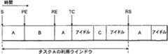
図4は、プロセッサ上での作業負荷の実行、およびタスクAの履歴ウインドウの予測を概略的に示す。図4の横軸は時間を示す。タスクAは、まず時間Sにおいて実行を開始し、その後多数のタスク毎のデータ構造が初期化設定される。次の4個の情報、即ち(i)作業カウンタの現状(ii)現在の(リアル)タイム(iii)アイドル・タイム・カウンタの現状、および(iv)タスクが実行を開始したことを示す論理レベル「1」に実行ビットを設定する、に対応するこれらデータ構造には4つある。作業カウンタ、リアル・タイム・カウンタ、およびアイドル・タイム・カウンタを用いてタスクAに関連するプロセッサ利用を予測し、引き続きAの性能要求を予測する。タイムPEでは、タスクAの実行は完了していないが、別タスクであるタスクBによってプリエンプトされている。プリエンプトが行われるのは、現在実行中のタスクよりも別のタスクの方が高い優先度を有するとタスクスケジューラ114が判定した時である。タスクAがプリエンプトされると、実行ビットは論理レベル「1」で維持され、タスクにはなお完了すべき作業があることを示す。タイムREにおいては、タスクAは実行を再開し、スケジュールを立て直され、タイムTCにおいて実行が完了するまで実行し続け、その後で自発的に処理タイムを放棄する。完了すると、タスクAはシステムコールを開始し、プロセッサを別のタスクに譲る。タイムTCにおいてタスクAが完了すると、実行ビットは論理レベル「0」にリセットされる。 FIG. 4 schematically illustrates execution of a workload on a processor and prediction of a history window for task A. The horizontal axis in FIG. 4 indicates time. The task A first starts executing at time S, and thereafter, a data structure for each of a number of tasks is initialized. The following four pieces of information: (i) the current state of the work counter, (ii) the current (real) time, (iii) the current state of the idle time counter, and (iv) a logical level indicating that the task has begun execution. There are four of these data structures corresponding to setting the execution bit to "1". The working counter, the real time counter, and the idle time counter are used to predict the processor utilization associated with task A, and then to predict A's performance requirements. In the time PE, the execution of the task A has not been completed, but has been preempted by another task B. Preemption occurs when the
タイムTCの後にはアイドル期間があり、つぎに別のタスクCの実行が続き、その後アイドル期間となる。タイムRSにおいて、タスクAは2度目の実行を開始する。タイムRSにおいてタスクAに関連するラン・ビットは「0」状態であることは、タスクAの性能要求を算出することを可能にする情報が存在するので、差し迫ったタスクAの再実行用にプロセッサのターゲット性能レベルを設定することができることを示している。所与のタスク用利用履歴ウインドウは所与のタスクの最初の実行の開始から所与のタスクのその後の実行の開始までの期間であると規定し、さらに関連ウインドウ内の所与のタスクの少なくとも1つのプリエンプト・イベント(この場合、AはREの時点においてタスクBによってプリエンプトされる)を含むものとする。したがって、このケースにおいては、タスクAの利用履歴ウインドウを、タイムSからタイムRSまでの期間と規定する。このウインドウにおけるタスクAのターゲット性能レベルは以下のように算出される。
WorkEstNew=(k×WorkEstOld+Workfse)/(k+1)
DeadlineNew=(k×DeadlineOld+(Workfse+Idle
))/(k+1)
この式において、kは荷重係数であり、アイドル(Idle)は図4におけるタイムSからタイムRSまでの時間間隔における秒単位のアイドル・タイムであり、タスクAのデッドラインは(Workfse+Idle)であると規定する。この特定の例においては、図4におけるタスクBのようなプリエンプト・タスクの検出を行うことはタスクごとの利用履歴ウインドウを判定する際にアルゴリズムを導く。タスクAの次のプリエンプトしないスケジューリングの前に実行されるタスク処理は、タスクAの実行と高度に対応付けられる場合が多い。タイム時点TCとRSとの間のアイドル・タイムは、「スラック(slack)」であって、これは性能レベルを下げてプロセッサ実行することによって回復させることが可能である。しかしながら、タスクCは性能レベル算出に含まれる。何故なら、それは利用可能なスラックを減少させるからである。After the time TC, there is an idle period, followed by the execution of another task C, and then the idle period. At time RS, task A starts executing for the second time. The fact that the run bit associated with task A in the time RS is in the “0” state indicates that there is information that allows the performance requirement of task A to be calculated. Indicates that the target performance level can be set. The usage history window for a given task defines the duration from the start of the first execution of the given task to the start of the subsequent execution of the given task, and at least one of the given tasks in the associated window. Assume one preemption event, where A is preempted by task B at the time of the RE. Therefore, in this case, the usage history window of task A is defined as a period from time S to time RS. The target performance level of task A in this window is calculated as follows.
WorkEstNew = (k × WorkEstOld + Workfse ) / (k + 1)
DeadlineNew = (k × DeadlineOld + (Workfse + Idle)
)) / (K + 1)
In this equation, k is a load coefficient, idle is the idle time in seconds in the time interval from time S to time RS in FIG. 4, and the deadline of task A is (Workfse + Idle). It is specified that there is. In this particular example, detecting a preempted task, such as task B in FIG. 4, guides the algorithm in determining the usage history window for each task. Task processing executed before the next non-preemptive scheduling of task A is often highly associated with execution of task A. The idle time between the time instants TC and RS is a "slack", which can be recovered by running the processor at a reduced performance level. However, task C is included in the performance level calculation. Because it reduces the available slack.
WorkEstNewおよびDeadlineNewの上記の式はそれぞれ指数的に減少する平均値を表す。そのように指数的に減少する平均値は、新しくない推定値に一層大きな影響を及ぼすより新しい推定値を考慮する。荷重係数kは指数的に減少する平均値に関連するパラメータである。k=3の値は効果的に作用したことが判明し、この小さな値はそれぞれの推定値は良好であることを示している。作業プレディクタおよびデッドライン・プレディクタの状況を別々に常に把握することによって、性能予測は利用履歴ウインドウの長さによって評価される。これによってより大きなウインドウサイズに関係付けられた性能推定値が性能予測において優位に立つものではないことが保証される。このアルゴリズムの性能レベル・インジケータPerfperspective−basedは2つの指数的に減少する平均値の比率、即ち、Perfperspective−based=WorkEstNew/DeadlineNewによって得られる。別々の性能レベル値をタスクごとに算定する。本技法の方策によれば、所与のタスクに対する作業推定値WorkEstは、50ミリ秒と150ミリ秒との間の作業負荷依存の時間間隔で算出し直す。しかしながら、WorkEstはタスクごとの基準で算出され、各実行されたタスクはそれぞれの適切なタスク主体のWorkEst値を活用するので、WorkEstは5乃至10ミリ秒毎に実際には調整される(タスク切替えイベントを反映する)。このアルゴリズムはインターバルベース(interval−based)のアルゴリズムとは異なり、利用推定値をタスク毎に別々に導き、また、利用履歴ウインドウの大きさをタスク毎の基準で調整する。公知の統一性能設定アルゴリズムは指数的に減少する平均値を用いるが、このアルゴリズムが算出するのは、タスクを主体とした利用履歴ウインドウにのタスクベースの平均値ではなく、固定利用履歴ウインドウ(10乃至50ミリ秒)用の全ての性能タスクにの全体的平均値である。The above equations for WorkEstNew and DeadlineNew each represent an exponentially decreasing average. Such exponentially decreasing averages take into account more recent estimates that have a greater effect on the less recent estimates. The weighting factor k is a parameter related to the exponentially decreasing average value. A value of k = 3 was found to work effectively, and this small value indicates that each estimate is good. By keeping track of the work predictor and deadline predictor status separately, performance predictions are evaluated by the length of the usage history window. This ensures that the performance estimate associated with the larger window size is not dominant in performance prediction. The performance level indicator Perfperspective-based of this algorithm is obtained by the ratio of two exponentially decreasing averages: Perfperspective-based = WorkEastNew / DeadlineNew. Separate performance level values are calculated for each task. In accordance with the techniques of the present technique, the work estimate WorkEst for a given task is recalculated at a workload dependent time interval between 50 and 150 ms. However, the WorkEst is calculated on a task-by-task basis, and since each executed task utilizes its appropriate task-based WorkEst value, the WorkEst is actually adjusted every 5 to 10 milliseconds (task switching). Events). This algorithm differs from an interval-based algorithm in that usage estimates are separately derived for each task, and the size of the usage history window is adjusted on a task-by-task basis. The known unified performance setting algorithm uses an average value that decreases exponentially. However, this algorithm calculates not a task-based average value in a task-based usage history window but a fixed usage history window (10乃至 50 ms) is the overall average for all performance tasks.
本技法のパースペクティブベースのアルゴリズムでは、新たな非双方向CPUに結びついたタスクがプリエンプトされずにプロセッサを長時間利用する状況が発生することを回避することが必要である。これにより、性能レベルがタスクに順応して大幅な待ち時間を招来する可能性がある。何故なら利用履歴ウインドウが規定されるのは、タスクが一旦少なくとも1度プリエンプトされたときだけであるからである。不要な性能順応待ち時間を回避するためには、上位の閾値を作業推定値が算出されない非プリエンプト時間期間用に設定する。特に、プリエンプトされることなくタスクが100ミリ秒続くと、その作業推定値はデフォルト値によって算出し直される。100ミリ秒という値を選択したのは、別々の双方向アプリケーション性能インジケータを生成する主要階層レベル210を介して、もっと厳しいアプリケーション履歴ウインドウが双方向アプリケーション用に確保されることを考慮したものである。更に考慮したことは、100ミリ秒ウインドウ閾値によって行われることが見込まれるユーザ・アプリケーションのクラスだけが、実行におそらく数秒または数分かかるコンパイルのような、コンピュータ的に負荷のかかるバッチ・ジョブであるということである。そのようなケースでは、追加の100ミリ秒(0.1秒)の実行時間は性能的には重大とは考えられない。 In the perspective-based algorithm of the present technique, it is necessary to avoid a situation where a task associated with a new non-bidirectional CPU is not preempted and uses the processor for a long time. This can lead to significant waiting times as the performance level adapts to the task. This is because the usage history window is defined only once the task has been preempted at least once. To avoid unnecessary performance adaptation wait times, a higher threshold is set for the non-preemption time period during which no work estimate is calculated. In particular, if a task lasts 100 ms without being preempted, its work estimate is recalculated with the default value. The choice of a value of 100 milliseconds takes into account that a more stringent application history window is reserved for interactive applications via the
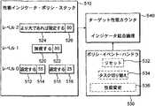
図5は、図2の3層階層の性能ポリシ・スタックの実現を概略的に示す。その実現は性能インジケータ・ポリシ・スタック510およびポリシ・イベント・ハンドラ(policy event handler)530を備え、これらの各々は情報をターゲット性能カルキュレータ(clculator)540に出力する。ターゲットの性能カルキュレータ540は4つの性能設定アルゴリズムからの結果を照合するように機能する。4つの性能設定アルゴリズムとは、最上層の双方向アルゴリズム、中層のアプリケーション主体のアルゴリズム、および2つの異なるより低層のアルゴリズムのことである。4つのアルゴリズムは同時に実行可能である。ターゲットの性能カルキュレータ540は、ポリシ・スタック510によって生成される多数(この場合は4つ)の性能インジケータから単一の全体目標性能レベルを導きだす。ポリシ・スタック510はポリシ・イベント・ハンドラ530、およびターゲット性能カルキュレータ540と一緒に多数の性能設定ポリシ用の適応性のあるフレーム作業を提供するため、スタックの各レベルのポリシ・アルゴリズムはユーザによって適宜置き換え又は交換される。したがって、性能ポリシ・スタックは、ユーザがカスタム化した性能設定ポリシを中に組み込むことが可能な実験用プラットフォームを提供する。 FIG. 5 schematically illustrates the implementation of the three-tier performance policy stack of FIG. The implementation includes a performance
多数の性能設定アルゴリズムのそれぞれを実行時イベント異なる特定カテゴリに対処するよう特化する。しかしながら、図5の実施形態の例では、4つの異なるアルゴリズムがあり、全てが異なる性能インジケータを出力するので、ソフトウエアは、全体の目標値設定に際し4つの性能インジケータのうちどちらを優先させるかに関して決定しなければならない。更に、各性能設定アルゴリズムは別個に実行することができ、かつ異なる時間に出力を生成することができると想定すると、全体的目標性能レベルが有効に算出される時間に関して決定を行わなければならない。また、多数の性能設定アルゴリズムがいずれも同一の処理イベントに基づいて決定を行う場合には、性能インジケータを結合する方法を考慮しなければならない。そうしないと、スプリアス(supurious)のターゲット更新が行われる場合がある。 Each of a number of performance setting algorithms is specialized to address different specific categories of runtime events. However, in the example of the embodiment of FIG. 5, since there are four different algorithms, all outputting different performance indicators, the software has a choice as to which of the four performance indicators to prioritize in setting the overall target value. You have to decide. Furthermore, assuming that each performance setting algorithm can be run separately and can produce output at different times, a decision must be made regarding the time at which the overall target performance level is effectively calculated. Also, when multiple performance setting algorithms make decisions based on the same processing event, a method of combining performance indicators must be considered. Otherwise, a spurious target update may occur.
これらの問題に対応するためは、ポリシ・スタック510アルゴリズムを例示のような3層の階層にまとめ、高い方の層にあるポリシが低い方(主要でない)の層から導かれた性能レベル要求より優先する権利を与える。したがって、レベル2のアルゴリズムはレベル1のアルゴリズムに優先し、次にレベル1のアルゴリズムはレベル0のアルゴリズムに優先することができる。各階層の層自体多数の代替性能設定アルゴリズムを含む場合があることを留意されたい。異なる性能設定アルゴリズムは階層内の自分の位置を認識しておらず、システム内のあらゆるイベントに基づいてその性能を決定することができる。所与のアルゴリズムが性能レベルを要求する際、そのアルゴリズムは、コマンドを所望の性能レベルと一緒にポリシ・スタック510に呈示する。ポリシ・スタックのアルゴリズム毎に、コマンド512、516、520、524および対応する性能レベル・インジケータ514、518、522および526からなるデータ構造が格納される。レベル1のアルゴリズムに該当するコマンドIGNORE520は、ターゲット性能カルキュレータ540に対し、全体の性能ターゲットを考慮して、関連の性能レベル・インジケータを無視すべきことを示す。レベル0のアルゴリズム双方のために指定されたコマンドSET512、516は、ターゲット性能カルキュレータ540が階層の低い方の層からのあらゆる性能レベル要求は考慮せずに対応する性能レベルを設定するようにする。しかしながら、SETコマンドは高い方の階層レベルからの性能レベルには優先することはできない。この実施形態においては、一方のレベル0のアルゴリズムは、性能を最高レベルの55%に設定するように要求したが、もう一方のレベル0のアルゴリズムは、性能を最高レベルの25%に設定するよう要求した。ターゲット性能カルキュレータは、オペレータを用いてこれら2つの優先度が同等の要求を結合する。この場合レベル0の性能インジケータとしては、55%値を選択することが好ましい。レベル2においては、コマンド「SET IF GREATER THANより大であれば設定」が、80%の性能インジケータと共に指定された。この「SET IF GREATER THAN」コマンドは、もし全体のターゲット性能レベルが低い方の階層レベルからの性能インジケータのどれよりも大きい場合には、ターゲット性能カルキュレータ540はこれを80%に設定すべしと定めている。この場合、全体のターゲットが実際に最高性能の80%に設定されるようにするために、レベル0の性能インジケータは55%とし、レベル1の性能インジケータは無視されるべきである。 To address these issues, the
アルゴリズム毎に極最近算出された性能レベル・インジケータはポリシ・スタック510によってメモリに格納されるので、それぞれの且つあらゆる性能設定アルゴリズムを呼び出す必要なしに、ターゲット性能クロック540は新たな全体のターゲット値をいつでも算出することができる。スタックのアルゴリズムの1つによって新たな性能レベル要求が算出されると、ターゲット性能カルキュレータはコマンド性能データ構造のコンテンツを低層から上に向かって評価し、更新された全体ターゲット性能レベルを計算する。したがって、図5の例において、レベル0では、全体予測を55%に設定し、レベル1では55%に留め、レベル2では全体予測を80%に変更する。性能設定アルゴリズムのそれぞれを(システム内の処理イベントによって)作動させ、性能設定アルゴリズムの全てが応答しそうな共通のイベント集合があるときにはいつでも新たな性能レベルを算出する。これらのイベントはポリシ・イベント・ハンドラ530によって監視され、且つ目印が付けられ、ポリシ・イベント情報をターゲット性能カルキュレータ540に提供する。この特別のイベント・カテゴリはリセット・イベント532、タスク・スイッチ・イベント534、および性能変更イベント536を備える。性能変更イベント536は各性能設定アルゴリズムにプロセッサの現在の性能レベルを知らせる通知であるが、それは通常はポリシ・スタック510の性能要求は変更しない。ポリシ・イベント532、534、536のこの特別のカテゴリに対し、アルゴリズムの1つが最新の性能・レベル・ インジケータを発行する毎に、全体ターゲット・レベルが計算し直されることはない。逆に、ターゲット性能レベルの算出は調整されるので、算出は全ての関連のある性能設定アルゴリズムのイベント・ハンドラが全て呼び出された後、イベント通知毎に一回だけ行われる。 Since the most recently calculated performance level indicators for each algorithm are stored in memory by the
デバイス・ドライバまたはデバイスのそれら自体にアプリケーション・プログラム・インターフェース(API)が備えることができる。これにより個々のデバイスはポリシ・スタック510および/またはポリシ・スタックの個々の性能設アルゴリズムに動作状況に重要な変化があればすべて知らせることができる。これにより性能設定アルゴリズムは、ターゲット性能レベルの算出し直しをトリガーすることができ、したがって動作条件の変化への素早い順応を促す。例えば、プロセッサ主体のCPUに結びついたタスクが開始すると、デバイスによって通知をポリシ・スタック510に送ることができる。かかる通知は任意であり、性能設定アルゴリズムは、これを受領した際に応答してもよいが、しなくともよい。 An application program interface (API) may be provided in the device driver or in the device itself. This allows individual devices to be aware of any significant changes in operating conditions in the
図6は本技法による作業追従カウンタ600を概略的に示す。作業追従カウンタ600は、ソフトウエア制御モジュール620およびハードウエア制御モジュール630を有する増分値レジスタ610、作業カウント値レジスタおよび時間カウント値レジスタからなるアキュムレータ640、時間ベースレジスタ646、リアル・タイム・クロック650、および制御レジスタ660を備える。この実施形態の例の作業追従カウンタは、公知のタイムスタンプ・カウンタおよびCPUサイクル・カウンタとは異なり、カウンタ増分値はプロセッサによって行われる実際の作業に比例するか、またはカウント値が増分される時間に近い。増分値レジスタ610は、カウンタ・サイクル毎にプロセッサによって行われた作業を推定する実行作業カルキュレータを備える。完了した作業の推定値はソフトウエア・モジュール620および/またはハードウエア制御モジュール630を介して得られる。ソフトウエア制御モジュール620は増分値を現在のプロセッサ速度と対応付ける簡単な作業完了算出を実施する。プロセッサが最高性能の70%で実行している場合、増分値は0.7となるが、プロセッサが最高性能の40%で実行している場合、増分値は0.4となる。カウンタ・サイクルの間プロセッサはアイドルであることをソフトウエア制御モジュール620が検出すると、増分値はゼロに設定される。作業追従カウンタの代替実施形態では、更に高度なソフトウエア・アルゴリズムを用いて改良された作業完了推定値を算出する。 FIG. 6 schematically illustrates a work tracking counter 600 according to the present technique. The
表1は、(このケースでは、より高い速度からより低い速度までの)2つの異なるプロセッサ速度の間の性能レベル変遷を考慮した時の、CPUに結びついたループおよびMPEGビデオ・作業負荷に対する予想した実行時間の継続時間と実際の実行時間との継続時間との間のパーセンテージによる差異を提供する測定データを一覧表示する。その結果は、3つの明瞭なプロセッサ性能レベル、即ち(表の一番左の縦列に明記した)300、400および500MHzにおける変遷後の実行に基づいている。表1の最上横列は、最初の性能レベルを列記し、そこから一番左の縦列における対応するプロセッサ速度へと変遷が行われる。CPUバウンドのループ上では、予測測定値と実際の測定値との差はノイズからは区別がつかない。しかるにMPEG作業負荷に関しては、プロセッサ周波数の100MHz段階毎に約6%乃至7%の誤りペナルティーがある。これらの作業負荷の最大誤差は20%未満(19.4%)であり、これは固定可能な性能レベルがほんの僅かしかないシステムにとっては容認可能と看做される。しかしながら、システムにおいて選択可能な、最小から最大プロセッサ性能レベルの利用可能な領域は増大し、各性能レベル段階の領域は減少するので、プロセッサ速度より正確な作業推定量が求められそうである。
代替実施形態の例の更に高度なアルゴリズムは、作業完了はプロセッサ速度と直接比例するとの仮説を立てるのではなく、(メモリ・アクセスのような重要なイベントを常に監視するカウンタを介して)命令プロファイルを監視することに係るより正確な作業完了推定技法、および作業負荷の予想減少率および実際の減少率を用いる。更に代替実施形態は、キャッシュのヒット率およびメモリ・システムの性能インジケータを用いて作業完了推定を改良する。なお別の実施形態の例は、ソフトウエアを用いて、バックグランドのオペレーティング・システム・タスクを実行するのに用いられた処理時間比率に対する(有用な作業完了に匹敵する)プログラミング・アプリケーションを実行するのに用いられる処理時間比率を監視する。 The more sophisticated algorithm of the alternative embodiment example does not hypothesize that work completion is directly proportional to processor speed, but rather the instruction profile (via a counter that constantly monitors important events such as memory accesses). And more accurate work completion estimation techniques for monitoring the work load, and expected and actual reductions in workload. Further, alternative embodiments improve work completion estimates using cache hit rates and memory system performance indicators. Yet another example embodiment uses software to execute a programming application (equivalent to useful work completion) to the processing time ratio used to perform background operating system tasks. Monitor the processing time ratio used for
ハードウエア制御モジュール630は、プロセッサが2つの固定性能レベル間で切り替え中であるときは、変遷時の期間であっても作業完了を推定することができる。プロセッサ性能変遷毎に、20マイクロセカンドくらいの停止があり、その間にはプロセッサいかなる命令も発しない。この休止は位相同期ループを新たなターゲット周波数と同期を取り直すために必要な時間のためである。更に、プロセッサ周波数が変化できないうちに、電圧を新たなターゲット周波数用の適切な値に安定化させなければならない。したがって、最高1ミリ秒までの変遷時間があり、その間にプロセッサは元のターゲット周波数で動作しているが、(電圧は新たなターゲット・レベルに設定されているので)エネルギーは新たなターゲット・レベルで消費されている。周波数は中間周波数段階を介していくつかの段階で増加してゆき性能レベルに影響を与える場合がある。そのような変遷期間中でプロセッサの周波数が動的に変化している時には、ハードウエア制御モジュール630はソフトウエアが認識している動的変化を考慮に入れて、増分値レジスタを更新するように動作可能である。この実施形態の例では、ハードウエアおよびソフトウエア制御モジュール620、630の双方を用いて行われた作業を算出するが、代替実施形態の例では、これら2つのモジュールの内の一方だけを用いて行われた作業を推定することができる。 When the processor is switching between two fixed performance levels, the
アキュムレータ・モジュール640は、増分値レジスタ610からの増分値を定期的に読み込み、この増分値を作業カウント値レジスタに格納された累算和に加算する。作業カウント値レジスタは、クロック・チック(clock−tick)毎に作業カウント値を増分する。クロック・チックはリアル・タイム・クロック650から導かれた時間信号である。所定の時間間隔の間に行われた作業を測定するには、アキュムレータ・モジュール640に格納された作業カウント値を2度、即ち1度は所定の時間間隔の初めに、もう1度はその終わりに読み込む。これら2値間の差異によって、所定の時間間隔の間に行われた完了作業が表示される。 The
また、リアル・タイム・クロック650は、レジスタ644に格納されたタイム・カウント値が増分される速度を制御する。このタイム・カウント値レジスタは作業カウント値と同じ時間ベースで機能するが、完了した作業よりむしろ経過した時間測定に用いられる。時間カウンタおよび作業完了カウンタの双方を有すると性能設定アルゴリズムは促進される。タイム・ベース・レジスタ646は、複数のプラットフォームへの互換性および秒への変換目的で備えられている。タイム・ベース・レジスタが2つのカウンタ642、644の時間ベース(周波数)を指定するように機能するため、時間は正確でムラがなく、即ち、タイム・カウント値レジスタに格納された累算値は経過時間をミリ秒単位で表示する。制御レジスタ・モジュール660は、各カウンタに1つずつの2つの制御レジスタからなる。カウンタは、適切な制御レジスタを介してイネーブル、ディスエーブルにする、またはリセットすることができる。
図7は、作業負荷特性に応じて多数の異なる固定性能レベルを提供することができる装置を概略的に示す。この装置は、CPU710、リアル・タイム・クロック720、電源制御モジュール730、および図6の作業追従カウンタの増分値レジスタ610を備える。電源制御モジュール730は、固定された性能レベルの内のどれをCPUは実行させるように現在設定されているかを判定し、リアル・タイム・クロック720用に適切なクロック周波数を選択する。電源制御モジュール730は現在のプロセッサ周波数に関する情報を増分値レジスタ610に入力する。したがって、増分値はプロセッサ周波数に比例し、次にプロセッサ周波数はプロセッサによる有用な作業完了の推定値を与える。 FIG. 7 schematically illustrates an apparatus that can provide a number of different fixed performance levels depending on workload characteristics. This device includes a
ポリシ・スタック510の性能設定アルゴリズムの多くは、所与の時間間隔(ウインドウ)の間にプロセッサの利用履歴を用いてプロセッサの適切な今後のターゲット速度を推定する。あらゆる性能設定ポリシの主たる目的は、プロセッサ周波数および電圧レベルを適切なターゲット性能レベルに下げることによって実行開始からタスク・デッドラインまでの期間におけるプロセッサの稼働時間を最大化することである。 Many of the performance setting algorithms of the
ターゲット性能レベルを実質的に予測可能とするため、インテリジェント・エネルギー・マネージャ120は所与の時間間隔の間にプロセッサが行った実際の作業を追従するための抽出を行う。この作業完了の抽出により、プラットフォーム間で異なる可能性のある特定のハードウエア・カウンタのいかんにかかわらず、性能変更およびアイドル・タイムは考慮することができる。本技法では、時間間隔の間の作業測定推定値を得るため、各性能設定アルゴリズムに「作業構造」データ構造を割り当てる。時間間隔の開始時には「作業開始機能」を、時間間隔の終わりには「作業停止機能」を呼びだすように各アルゴリズムを設定する。作業完了の測定中に、作業構造のコンテンツは自動的に更新され、プロセッサのそれぞれの性能レベルによって評価されたアイドル・タイムの比率および利用されたプロセッサ・タイムの比率を明記する。次に作業構造に格納された情報を用いて、最大速力に等しい作業値(Workfse)を計算し、後にこれを用いてターゲット性能レベルを予測する。ソフトウエアのインテリジェント・エネルギー・マネージャ120において実行されるこの作業完了の抽出機能性は、インテリジェント・エネルギー・マネージャ120に対し、使いやすいインターフェースと共に性能値予測アルゴリズム・デベロッパを提供する。また、作業完了の抽出は、本技法の性能設定システムの異なるハードウエア・アーキテクチャへのポーティングを簡略化する。To make the target performance level substantially predictable, the
代替ハードウエア・プラットフォーム間の大きな違いの1つはプラットフォーム上での時間の測定方法である。特に、あるアーキテクチャは、タイムスタンプ・カウンタを介して低いオーバーヘッドのサイクル・カウント方法を提供するが、別のアーキテクチャは、ユーザに外部からプログラム可能なタイマー割り込みを提供するだけである。しかしながら、タイムスタンプ・カウンタが提供されたとしても、それらは必ずしも同じものを測定するわけではない。例えば、ハードウエア・プラットフォームの第1のカテゴリは現行のインテルペンティアム(登録商標)およびARMプロセッサの双方を含む。これらのプロセッサでは、タイムスタンプ・カウンタは、CPUサイクルをカウントし、カウント速度はプロセッサの速度に応じて変動してプロセッサがスリープ・モードに入るとカウントを停止する。ハードウエア・プラットフォームの第2のカテゴリはクルーソー(Crusoe)プロセッサを含み、サイクルをプロセッサの最高速度で一貫してカウントし、プロセッサがスリープ・モードになっても最高速度でカウントを増分し続けるタイムスタンプ・カウンタを実現する。作業完了の抽出は、ハードウエア・プラットフォームのこれら2つの代替カテゴリの双方において本ターゲット性能設定技法が実現されるのを促進する。 One of the major differences between alternative hardware platforms is the way time is measured on the platform. In particular, some architectures provide a low overhead cycle counting method via a timestamp counter, while others only provide the user with an externally programmable timer interrupt. However, even if time stamp counters are provided, they do not necessarily measure the same. For example, the first category of hardware platforms includes both current Intel Pentium and ARM processors. In these processors, the timestamp counter counts CPU cycles, and the counting speed varies with the speed of the processor and stops counting when the processor enters sleep mode. The second category of hardware platforms includes the Crusoe processor, a timestamp that counts cycles consistently at the maximum processor speed and continues to increment counts at the maximum speed even when the processor goes to sleep mode. -Implement a counter. Extraction of work completion facilitates the implementation of this target performance setting technique in both of these two alternative categories of hardware platforms.
この実施形態において算出される作業推定Workfseは、最大性能の1/2で実行する所与の作業負荷は、実行、完了するまでに、プロセッサの最大速度で実行、完了した場合に比して必ずしも2倍かかるわけではないという事実を考慮しない。このカウンタの直感的な結果の1つの理由は、プロセッサのコアは減速するが、メモリ・システムは減速しないことである。その結果、コア対メモリ性能比率はメモリに有利に改善される。The work estimate Workfse calculated in this embodiment is such that a given workload running atの of the maximum performance is executed and completed at a maximum speed of the processor compared to when it is executed and completed. It does not take into account the fact that it does not always take twice. One reason for the intuitive result of this counter is that the processor core slows down, but the memory system does not. As a result, the core-to-memory performance ratio is advantageously improved for the memory.
シミュレーションを行って、公知の技法に対する本性能設定技法を評価した。特に、公知の技法は、トランスメタ・クルーソ(Transmeta Crusoe)・プロセッサに組み込まれた「ロングラン(LongRun)」電力マネージャである。トランスメタのクルーソ・プロセッサはプロセッサ・ファームウエアに組み込まれたロングラン電力マネージャを有する。ロングランは他の公知の電力管理技術とは異なり、電力管理を行うためにオペレーティング・システムを修正する必要性がない。ロングランはプロセッサの利用履歴を用いてクロック速度選択を導く。即ち、利用が多い場合にはプロセッサを加速し、利用が少ない場合には性能を下げる。更に従来型のプロセッサにおける場合と異なり、クルーソ・プロセッサでは電力管理ポリシは比較的容易に実現される。何故なら、動的バイナリ変換および最適化を行う隠れたソフトウエア層がプロセッサには既にあるからである。このシミュレーションは、ソフトウエア階層のそのように低い層において実現されるロングランのようなポリシが、いかに効果的に実行できるかを立証することを狙った。本技法は同一プロセッサ上でロングランと一緒に実行された。 Simulations were performed to evaluate this performance setting technique over known techniques. In particular, a known technique is the "LongRun" power manager built into the Transmeta Crusoe processor. Transmeta's cruso processor has a long-run power manager built into the processor firmware. Long run, unlike other known power management techniques, does not require modifying the operating system to perform power management. Long runs use the usage history of the processor to guide the clock speed selection. That is, the processor is accelerated when the usage is large, and the performance is reduced when the usage is small. Further, unlike in conventional processors, power management policies are relatively easy to implement in a Crusoe processor. This is because the processor already has a hidden software layer that performs dynamic binary conversion and optimization. This simulation aimed to prove how effectively long-run-like policies implemented at such a lower layer of the software hierarchy can be implemented. This technique was performed with long runs on the same processor.
シミュレーションは、100MHz性能レベル間隔で300MHzから600MHzまでの範囲の多数の固定性能レベルで稼働するトランスメタ・クルーソ5600プロセッサを用いたソニー・バイオ(Sony Vaio)PCG−CIVNノートブック・コンピュータ上で行った。シミュレーションは、リナックス(Linux)2.4.4−ac18カーネルの修正バージョンと共にマンドレーク(Mandrake)7.2オペレーティング・システムを用いた。比較評価において用いられた作業負荷には、PlaympegSDL MPEGプレーヤ・ライブラリ、PDFファイルを表示するアクロバット・リーダ(Acrobatt Reader)、テキスト編集用Emacs、ニュース閲覧用Netscape Mail and News 4.7、ウエブ・ブラウジング用Konqueror1.9.8、3次元ゲームとしてのXwelltris1.0.0がある。双方向シェル・コマンド(Interactive Shell Commands)用に用いられるベンチマークは約30分の間にユーザが行う種々雑多のシェル・オペレーションの記録であった。クルーソ・プロセッサの動的変換エンジンにより起こり得る変動性を回避するため、殆どのベンチマークは少なくとも2度実行して動的変換キャッシュをウオームアップし、最後の実行以外の全てからのデータは無視した。 Simulations were performed on a Sony Bio PCG-CIVN notebook computer using a TransMeta Cruso 5600 processor operating at multiple fixed performance levels ranging from 300 MHz to 600 MHz at 100 MHz performance level intervals. . The simulation used the Mandrake 7.2 operating system with a modified version of the Linux 2.4.4-ac18 kernel. Workloads used in the comparative evaluation include a Plaympeg SDL MPEG player library, an Acrobat reader for displaying PDF files, Emacs for text editing, Netscape Mail and News 4.7 for browsing news, and Web browsing for browsing. There is Konqueror 1.9.8, Xwelltris 1.0.0 as a three-dimensional game. The benchmark used for Interactive Shell Commands was a record of miscellaneous shell operations performed by the user in about 30 minutes. To avoid possible variability due to the Cruso processor's dynamic translation engine, most benchmarks ran at least twice to warm up the dynamic translation cache and ignored data from all but the last run.
本技法による性能設定アルゴリズムはそのプラットフォームに邪魔にならないようになされた。シミュレーションのために、本技法はリナックスが組み込まれた10ミリ秒のレゾリューション・タイマの作用方法を変更することなく、ミリ秒以下のレゾリューション・タイマを備えた。これは、(タイマ・イベントをチェックする)タイマー・ディスパッチ・ルーチンを、スケジューラおよびシステムコールのような度々実行されるカーネルの部分の上に重畳することによって達成される。 The performance setting algorithm according to the present technique was made out of the way of the platform. For simulation, the technique provided a sub-millisecond resolution timer without changing the way the 10-millisecond resolution timer incorporating Linux works. This is achieved by superimposing a timer dispatch routine (checking for timer events) over portions of the kernel that are executed frequently, such as schedulers and system calls.
本技法による性能設定アルゴリズムは、特定のシステムコールが双方向エピソードを探すのを遮断することを可能にするカーネルに対するフックを有し、あらゆるタスク・スイッチ上で呼び出されるようになされているので、少数の命令をこれらのフックに加算し、タイマ・ディスパッチを管理するのは直接的であった。タイムスタンプ・カウンタの読み込み、次のタイマ・エベントのタイム・スタンプに対する比較、および成功時にタイマー・ディスパッチ・ルーチンへの分岐を実行することによってあらゆるフックは増大した。この方策はミリ秒以下の精度のタイマには負けることは実際に判った。 The performance setting algorithm according to this technique has a hook to the kernel that allows certain system calls to be blocked from looking for interactive episodes, and is made to be invoked on every task switch, Adding these instructions to these hooks and managing timer dispatch was straightforward. Every hook was augmented by reading the timestamp counter, comparing the next timer event to the timestamp, and branching to the timer dispatch routine on success. It has been found that this strategy loses to sub-millisecond timers.
下記の表2は、シミュレーションに関するタイマー統計を詳述している。最悪の場合のタイマー・レゾリューションが、スケジューラの10ミリ秒(表2に一致しないように見える)のタイム・クオンタム(time quantum)によって結び付けられている。しかしながら、本技法による性能設定アルゴリズムでは、イベントは、タイマー・トリガーの近傍において通常行われる測定にかかわるので、達成されたレゾリューションは適切であると看做された。プロセッサがスリープ・モード状態のときは、システムのソフト・タイマーが時間刻みを停止させることは有用であることが判った。何故なら、このことは、タイマーを中断しても実行中のオペレーティング・システムおよびプログラム・アプリケーションのスリープ特性を変えることはないことを示しているからである。用いられたタイマーは高いレゾリューションを有していたが、オーバーヘッドは低かった。 Table 2 below details timer statistics for the simulation. The worst case timer resolution is tied to the scheduler's 10 millisecond (which does not seem to match Table 2) time quantum. However, in the performance-setting algorithm according to the present technique, the resolution achieved was deemed appropriate, since the event involved a measurement normally taken in the vicinity of the timer trigger. When the processor is in sleep mode, it has been found useful for the system's soft timer to stop the ticks. This is because interrupting the timer does not change the sleep characteristics of the running operating system and program applications. The timer used had a high resolution but low overhead.
タイマーのこれらの有用な特徴によって、能動モードおよび受動モードの双方を有するインプリメンテーションの展開が促進された。能動モードにおいては、本技法の性能設定アルゴリズムが制御を行った。受動モードにおいては、内蔵のロングラン電力マネージャは性能を管理するが、本技法のインテリジェント・エネルギー・マネージャは実行および性能変更のオブザーバとして作用した。
ロングランによって起こる性能変化を監視することはタイマー・ディスパッチ・ルーチンと同様に遂行された。本技法によるインテリジェント・エネルギー・マネージャ120は、機械特定レジスタを介してプロセッサの性能レベルを定期的に読み込み、この結果を以前の値と照合した。これら2つの値が異なった場合、その変異をバッファにログインした。本技法によるインテリジェント・エネルギー・マネージャは追従機構を含み、重要なイベントのログをカーネル・バッファに保持する。このログは異なるポリシからの性能レベル要求、タスク・プリエンプション、タスクID(識別子)、およびプロセッサの性能レベルを含む。シミュレーション実行の際、同じ実行ランの間にロングランを本技法の性能設定アルゴリズムと対照することは可能であった。ロングランは性能設定を制御し、一方、本技法のインテリジェント・エネルギー・マネージャ120は、もし自分が制御を行っていたら、同じ作業負荷上で行ったであろう決定を出力するように動作可能であった。シミュレーション方策を用いて、公知のロングラン技法と本技法との間の双方向ベンチマークの繰り返し不能のラン間の違いを客観的に評価した。These useful features of the timer have facilitated the deployment of implementations having both active and passive modes. In the active mode, the performance setting algorithm of the present technique controlled. In passive mode, the built-in long-run power manager manages performance, while the intelligent energy manager of the present technique acted as an observer of execution and performance changes.
Monitoring the performance changes caused by the long run was performed similarly to the timer dispatch routine. The
測定および性能設定技法を用いることのオーバーヘッドを評価するため、本技法による性能設定アルゴリズムにはマーカーを備え、実行時に性能設定アルゴリズム符号に消費される時間を記録した。ペンティアムII(登録商標)上での本技法の実行時間のオーバーヘッドは約0.1%ないし0.5%であることが判明したが、トランスメタ・クルーソ・プロセッサ上ではオーバーヘッドは1%と4%との間であった。「VMWare」および「ユーザ・モード・リナックス」(UML)のような仮想機械における測定によって、本技法による性能設定アルゴリズムのオーバーヘッドは、従来のプロセッサ・アーキテクチャ上よりも仮想機械上の方が大幅に高い可能性があることが確認された。しかしながら、このオーバーヘッドはアルゴリズムの最適化によって効果的に下げることができた。 To evaluate the overhead of using the measurement and performance setting techniques, the performance setting algorithm according to the present technique was provided with a marker to record the time spent in the performance setting algorithm code during execution. The execution time overhead of this technique on a Pentium II® was found to be about 0.1% to 0.5%, while the overhead on a trans-meta-cruso processor was 1% and 4%. Was between. Measurements in virtual machines such as "VMWare" and "User Mode Linux" (UML) show that the overhead of the performance setting algorithm according to this technique is significantly higher on virtual machines than on traditional processor architectures. The possibility was confirmed. However, this overhead could be effectively reduced by optimizing the algorithm.
MPEG(Motion Pictures Expert Group)ビデオ再生は、検査を行った性能設定アルゴリズムの全てに関し困難な問題を提起した。一般に性能設定アルゴリズムは、システムに定期的に負荷をかけるが、性能要求はMPEGフレームの種類に応じて変動する可能性がある。その結果、性能設定アルゴリズムが比較的長い過去の(大きく変わりやすい)MPEGフレーム復号イベントに対応するタイム・ウインドウを用いて今後の性能要求を予測する場合、(典型的ではない)コンピュータ集中度のより高いフレーム用の期限を施行し損なう恐れがある。他方において、アルゴリズムが短い間隔だけを考慮すると、アルゴリズムは単一性能値のみに集中し、多数の設定間では急速に変動する。性能レベルが変動すると、その度に遷移遅延を招くので、異なる性能レベル間で急激な変動は望ましくない。ロングランに対するシミュレーション結果によって、MPEGベンチマークのこの変動習性が確認される。 MPEG (Motion Pictures Expert Group) video playback has presented a difficult problem with all of the performance setting algorithms tested. Generally, performance setting algorithms periodically load the system, but performance requirements may vary depending on the type of MPEG frame. As a result, when the performance setting algorithm predicts future performance requirements using a time window corresponding to a relatively long (largely variable) past MPEG frame decoding event, the (untypical) computer intensive Failure to enforce deadlines for high frames. On the other hand, if the algorithm only considers short intervals, the algorithm concentrates on only a single performance value and varies rapidly between multiple settings. A sudden change between different performance levels is undesirable, as each change in performance level causes a transition delay. Simulation results for long runs confirm this variation behavior of the MPEG benchmark.
本技法は、階層の最上層にある双方向性能特定アルゴリズムに基づくことによってMPEG作業負荷が変動するというこの問題に対処し、最悪の場合の応答性を抑制する。したがって、階層の最下層にある更に旧来型の間隔主体のパースペクティブ・アルゴリズムは、性能レベル要求を更に長期にわたって考察することができる。 The present technique addresses this problem of fluctuating MPEG workload by being based on an interactive performance identification algorithm at the top of the hierarchy, and reduces worst-case responsiveness. Thus, a more traditional interval-based perspective algorithm at the bottom of the hierarchy can consider performance level requirements for longer.
図8は、種々のMPEGビデオを再生する「plaympeg」ビデオ・プレーヤ(http://www.lokigames.com/development/smpeg.php3)のシミュレーション測定結果を詳述した表である。ビデオ・プレーヤの内部変数の1部は露呈され、実行中にプロセッサ性能レベルを動的に変えた結果プレーヤが影響を受けた状況に関する情報を提供している。これらの数字は表のMPEG復号列に示されている。特に、「アヘッド(Ahead)」変数は、それぞれのフレーム復号がデッドラインに近づく状況を測定する。デッドラインへの接近は各ビデオ再生中の累積秒として表現されている。電力効率を最大化するには、アヘッド変数値をできるだけ0に近づけるが、プロセッサの最も緩慢な性能レベルは、アヘッド値をいかに多く下げられたとしても、低い方の制限を設ける。表の一番右側縦列の「定刻きっかり欄」には締め切りにきっちりと間に合ったフレームの総数が明記されている。定刻きっかりのフレームが増えるほど、性能設定アルゴリズムは論理的最適条件に近づく。図8の表の実行統計縦列のデータは、サブ・システムを監視するインテリジェント・エネルギー・マネージャ120によって収集された。ロングランに関する情報を収集するため、インテリジェント・エネルギー・マネージャ120を受動モードで用いて、プロセッサ性能レベルを制御することなく僅かの性能変化を収集した。アイドル欄には、(おそらくはハウスキーピングまたは単なるスピニング)カーネルのアイドル・ループにおいて消費された僅かの時間を明記し、一方スリープ欄には、プロセッサが低電力のスリープ・モードで実際に消費した僅かの時間が明記されている。図8の表から、これら性能測定値のそれぞれに関し、本技法の方がロングランよりも性能が優れていることがわかった。 FIG. 8 is a table detailing simulation measurement results of a “plaympeg” video player (http://www.lokigames.com/development/smpeg.php3) for playing various MPEG videos. Some of the video player's internal variables are exposed to provide information about situations in which the player has been affected as a result of dynamically changing processor performance levels during execution. These numbers are shown in the MPEG decoding column of the table. In particular, the "Ahead" variable measures the situation where each frame decoding approaches a deadline. Approach to the deadline is expressed as the accumulated seconds during each video playback. To maximize power efficiency, keep the ahead variable value as close to 0 as possible, but the slowest performance level of the processor places a lower limit, no matter how much the ahead value is reduced. In the rightmost column of the table, in the "timely exact column", the total number of frames exactly in time for the deadline is specified. The more frames on time, the closer the performance setting algorithm approaches the logical optimum. The data in the execution statistics column of the table of FIG. 8 was collected by the
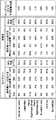
図9は、各作業負荷実行中に収集されたプロセッサ性能レベル統計を列記している。各性能レベルにおける僅かな時間が作業負荷の実行中の全ての非アイドル・タイムの割合として計算されている。表の「平均性能」レベル縦列には、各作業負荷実行中の(最大性能の平均としての)平均性能レベルが明記されている。全てのケースにおいて、本技法を用いた場合の各作業負荷の平均性能レベルは、ロングランよりも低いので、最後の縦列には、ロングランに関して達成された平均性能低減が明記されている。ロングラン・作業負荷と本技法の作業負荷双方の再生品質は同一であり、即ち、フレーム速度は同一で、フレーム落ちはなかった。 FIG. 9 lists processor performance level statistics collected during each workload execution. The fraction of time at each performance level is calculated as a percentage of all non-idle time during the execution of the workload. In the "Average Performance" level column of the table, the average performance level (as an average of the maximum performance) during execution of each workload is specified. In all cases, the average performance level for each workload using this technique is lower than the long run, so the last column specifies the average performance reduction achieved for the long run. The playback quality of both the long-run workload and the workload of the present technique was the same, ie, the frame rate was the same and there were no dropped frames.
その結果は、本技法の方が既知のロングラン技法よりも正確に必要な性能レベルを予測することができることを示している。精度を高めたことにより、ベンチマーク実行中のプロセッサの平均性能レベルを11%ないし35%低減させる結果となった。作業負荷実行間の作業量は同一でなければならないので、平均性能レベルの低下は、現技法のインテリジェント・エネルギー・マネージャがイネーブルにされると、アイドル・タイムおよびスリープ・タイムの削減が予想できることを意味していた。この予想はシミュレーション結果によって確認された。同様に、現技法のインテリジェント・エネルギー・マネージャがイネーブルにされると、締め切りにきっちりと間に合わせるフレームの数は増加し、復号がその締め切りに先立つ場合、時間の累積量は減少する。 The results show that this technique can predict the required performance level more accurately than known long-run techniques. The increased accuracy has resulted in a reduction in the average performance level of the processor during benchmark execution by 11% to 35%. Since the amount of work between workload runs must be the same, the reduction in average performance level can be expected to reduce idle and sleep times when the current technology's intelligent energy manager is enabled. Was meant. This expectation was confirmed by simulation results. Similarly, when the intelligent energy manager of the current technique is enabled, the number of frames that catch up to the deadline increases, and the cumulative amount of time decreases if decoding precedes the deadline.
また、(図9の表の各縦列において太字で強調された)中央の性能レベルも大幅な減少を示している。殆どのベンチマークに関して、本技法による性能設定アルゴリズムは、実行時間の最大分数(>88%)の最大未満の単一性能レベルに定着するが、ロングランは通常、最大速度で実行するようにプロセッサを設定する。全般的なルールの例外は、「Danse De Cable」作業負荷であり、ここでは本技法による性能設定アルゴリズムは最も低い2つの性能レベルに定着し、これら2つのレベル間で変動する。この変動の理由は、クルーソ・プロセッサ上の特有の性能レベルによるものである。本技法による性能設定アルゴリズムは300MHzよりほんの僅かに高い性能レベルを選択したので、性能レベル予想が300MHz値の上下に変動するとターゲット性能レベルは最も近い2つの性能レベルに量子化された。既知のロングラン技法と本技法との間の最も注目すべき性能の違いは、ロングランは、かなりの量のプロセッサの作用を検出した際、性能レベルを極めて素早く高めることには非常に慎重であるように見えることである。 Also, the performance level in the middle (highlighted in bold in each column of the table of FIG. 9) shows a significant decrease. For most benchmarks, the performance setting algorithm according to the present technique will settle to a single performance level below the maximum of the maximum fraction of execution time (> 88%), but long runs typically configure the processor to run at maximum speed. I do. The exception to the general rule is the "Dance De Cable" workload, where the performance setting algorithm according to the present technique is rooted in the two lowest performance levels and varies between these two levels. The reason for this variation is due to the inherent performance level on the Cruso processor. Since the performance setting algorithm according to the present technique selected a performance level only slightly higher than 300 MHz, the target performance level was quantized to the two closest performance levels when the performance level expected fluctuated above and below the 300 MHz value. The most notable performance difference between the known long-run technique and the present technique is that long-runs are very cautious about increasing the performance level very quickly when detecting a significant amount of processor activity. Is to look at.
作業負荷の全てにわたって、ロングランの平均プロセッサ性能レベルは80%以下になることはなかったのに対し、本技法によって設定された性能レベルは「Red’s Nightmare small」ベンチマークに対してはなんと52%にまでに下がっている。本技法によるアルゴリズムは、ロングランより積極的であるが、サービス品質が損なわれたように思われると、素早く対応する。ロングランは双方向性能に関してはなんらの情報も有していないので、より短い時間のフレーム上で控えめに作用せざるを得ず、これが非能率につながっていることをシミュレーション結果は示している。 Over the entire workload, the long-run average processor performance level did not fall below 80%, whereas the performance level set by this technique was a whopping 52% for the "Red's Nightmare small" benchmark. It has gone down to. Algorithms according to this technique are more aggressive than long runs, but respond quickly if the quality of service appears to be impaired. The simulation results show that LongRun has no information about the bidirectional performance, so it has to work sparingly on shorter time frames, which leads to inefficiencies.
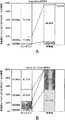
図10は、「Legendary(図10A)」と「Danse de Cable(図10B)」のタイトルの付いた2つの異なるMPEG映画の再生結果の2つのグラフからなる。各グラフは4つのプロセッサ性能レベル(300、400、500、および600MHz)のそれぞれにおいて、ロングランおよび本技法のために消費された僅かの時間を示している。各実行の再生品質は同一であるが、グラフからわかったことは、ロングラン技法が性能レベルを指定した際にプロセッサが最大性能未満において消費した時間よりも、本技法によるアルゴリズムを使用した場合にプロセッサが最大性能未満において消費した時間の方が大幅に長かったことである。図10Aに図示された「Legendary」映画の再生の結果は、本技法によるアルゴリズムは500MHzの性能レベルにおいて落ち着くことを示している。図10Bに示した「Danse de Cable」映画の結果は、本技法によるアルゴリズムを用いると、プロセッサは性能レベル、即ち、300MHzおよび400MHzの間で切替えたことを示している。これとは対照的に、これらの映画の双方に対し、ロングラン性能設定アルゴリズムは実行時間の大半の部分、600MHzの最高プロセッサ速度を選択した。 FIG. 10 consists of two graphs of the playback results of two different MPEG movies titled “Legendary (FIG. 10A)” and “Dance de Table (FIG. 10B)”. Each graph shows at each of the four processor performance levels (300, 400, 500, and 600 MHz) the long run and the fraction of time spent for the technique. Although the playback quality of each run is the same, the graph shows that the processor does not use the algorithm according to the long-run technique, rather than the amount of time the processor spends below the maximum performance when specifying the performance level. Is that the time spent below the maximum performance was significantly longer. The results of the playback of the “Legendary” movie illustrated in FIG. 10A show that the algorithm according to the present technique settles at a performance level of 500 MHz. The results of the “Dance de Cable” movie shown in FIG. 10B show that using the algorithm according to the present technique, the processor switched between performance levels, ie, 300 MHz and 400 MHz. In contrast, for both of these movies, the long-run performance setting algorithm chose the highest processor speed of 600 MHz for most of the run time.
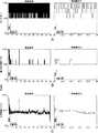
図11は、2つの異なる性能設定ポリシの特徴の質的洞察を提供する。ロングランは、性能レベルを素早く連続して上下に切り替え続けるが、システムのプロセッサ性能レベルは、本技法によって制御された場合、ターゲット性能レベルの近傍に留まる。図11A(横列最上部)は、ベンチマークがロングランと共にイネーブルにされた間のプロセッサの性能レベルを示す。図11Bおよび図11C(横列の中間部および最低部)は、ベンチマークは同じであるが、本技法のアルゴリズムはイネーブルにされた結果を示す。図11Bは、実行中の実際の性能レベルを示すが、11Cは、本技法による性能設定アルゴリズムが要求する性能レベルを(最大性能は同一と仮定して)任意の性能レベルで実行可能なプロセッサの上で反映している。場合によっては、本技法によるアルゴリズムによって算出された所望の性能レベルは、実際にはプロセッサ上で実現可能な最低性能レベル未満であることを留意されたい。 FIG. 11 provides qualitative insight into the characteristics of two different performance setting policies. Long runs continue to switch performance levels up and down quickly and continuously, but the processor performance level of the system remains near the target performance level when controlled by this technique. FIG. 11A (top row) shows the performance level of the processor while the benchmark was enabled with a long run. 11B and 11C (middle and bottom row) show the same benchmark, but with the algorithm of the present technique enabled. FIG. 11B shows the actual performance level during execution, while 11C shows the performance level required by the performance setting algorithm according to the present technique (assuming the same maximum performance). Reflected above. Note that in some cases, the desired performance level calculated by the algorithm according to the present technique is actually less than the lowest performance level achievable on the processor.
ここで双方向作業負荷上での2つの技法の比較のシミュレーション結果を検討する。双方向ベンチマークの実行を反復可能にすることは困難なため、双方向作業負荷の評価はマルチメディア・ベンチマークより相当難しい。この問題を回避するため、実測値を単純なシミュレーション技法と結合した。更に具体的に記せば、双方向ベンチマークは在来のロングラン電力マネージャの制御下で実行し、本技法によるインテリジェント・エネルギー・マネージャ120は受動モードで携わっただけなので、プロセッサの性能レベルを変更しようとしたのが実際には変更しなかったという性能設定決定を単に記録したに過ぎない。 Now consider the simulation results of the comparison of the two techniques on an interactive workload. Evaluating interactive workloads is much more difficult than multimedia benchmarks because it is difficult to make interactive benchmark executions repeatable. To avoid this problem, the measured values were combined with simple simulation techniques. More specifically, the bi-directional benchmark ran under the control of a conventional long-run power manager, and since the
図12は、双方の作業負荷の評価のためのシミュレーション・ランの間に収集された性能データを示す。図12Aは、ロングラン技法の(秒単位の)時間に対する百分比の性能レベルのグラフであり、このケースでは図示された結果は測定中のプロセッサの実際の性能レベルに対応する。図12Bは量子化性能レベルのプロットであり、図12Cは、現技法の性能設定アルゴリズムが、もしプロセッサを制御していたら設定したであろう時間関数としての生の性能レベルのプロットである。もしも本技法のアルゴリズムが実際に制御を行っていたら、その性能設定決定が実行時間に及ぼしたであろう影響はロングランによるものとは異なっていたであろうことを留意されたい。このため、グラフ12Bおよび12Cのグラフ上の時間軸は概算と看做すべきである。 FIG. 12 shows performance data collected during a simulation run for both workload evaluations. FIG. 12A is a graph of the performance level as a percentage of time (in seconds) for the long run technique, in which case the results shown correspond to the actual performance level of the processor being measured. FIG. 12B is a plot of the quantization performance level, and FIG. 12C is a plot of the raw performance level as a function of time that the performance setting algorithm of the current technique would have set if controlling the processor. Note that if the algorithm of the present technique were actually controlling, the effect that the performance setting decision would have had on the run time would have been different from that of a long run. For this reason, the time axes on the graphs 12B and 12C should be considered approximate.
統計におけるタイム・スキュー(time−skew)問題を回避するため、本技法によるシミュレーションの性能レベル・トレースを後処理し、ロングランではなく本技法を用いた結果による実行時間延長の影響を評価した。性能レベル・トレース全体を見るのでなく、双方向のエピソードだけに集中した。本技法の双方向性能設定アルゴリズムは、ユーザに直接影響を与える実行の継続時間を発見する機能性を備える。この技法はどのアルゴリズムが制御を行っているかに関係なく適正な測定値を示すので、この技法を用いてこの測定を集中させた。一旦双方向エピソードの実行領域が区切られると、エピソード中に行われた最高速度同等の作業はロングランおよび現技法用に算出された。測定中、ロングランはCPUの速度を制御し、現技法が制御を行う場合よりも高速で実行するので、現技法に対応した結果のエピソード継続時間は延長しなければならない。最初に、残りの作業を以下の式に従って現技法用に算出する。
WorkPresent technique Remaining=WorkLongRun−WorkPresent techniqueTo avoid the time-skew problem in the statistics, the performance level trace of the simulation according to the present technique was post-processed, and the effect of the execution time extension by the result using the present technique instead of the long run was evaluated. Instead of looking at the entire performance level trace, I focused solely on interactive episodes. The interactive performance setting algorithm of the present technique has the ability to find the duration of execution that directly affects the user. This technique was used to centralize this measurement, as it showed the correct measurement regardless of which algorithm was controlling it. Once the interactive region of an interactive episode was delimited, the top speed equivalent work performed during the episode was calculated for long runs and current techniques. During the measurement, the long run controls the speed of the CPU and runs faster than the current technique does, so the resulting episode duration corresponding to the current technique must be extended. First, the remaining work is calculated for the current technique according to the following equation:
WorkPresent technologyRemaining = WorkLongRun -WorkPresent technology
次に、本技法のアルゴリズムは、パニック閾値に到達した後に最大の速度で稼動する迄は、その予測速度で稼動し続けることを想定して、アルゴリズムがどの程度計算されたかに応じ、双方向エピソードの長さを引き伸ばすことが必要である。統計はそれに応じて調整した。この技法を用いた結果は、プロセッサを積極的に制御する本技法のアルゴリズムで走る(ベンチマークは同じであるが、双方向ロードは僅かに異なる)類似の作業負荷の上で観察したものに近いことがわかった。しかしながら、本技法によるアルゴリズムが実際に制御を行うと、性能設定決定の数は低減し、性能レベルの精度は高まった。 Next, the algorithm of the present technique depends on how much the algorithm has been calculated, assuming it will continue to run at its predicted speed until it runs at its maximum speed after reaching the panic threshold, depending on how interactive the episode is. It is necessary to lengthen the length of. Statistics have been adjusted accordingly. The results of using this technique are close to those observed on a similar workload running with the algorithm of this technique that actively controls the processor (same benchmark, but slightly different bidirectional loads). I understood. However, when the algorithm according to the present technique actually performed the control, the number of performance setting decisions was reduced and the accuracy of the performance level was increased.
図13は、上記のタイム・スキュー(time−skew)補正技法を用いて収集した統計を示す。図中の6個のグラフのそれぞれは2つの重なった列からなる。各グラフ上の左側の列はロングランに関係するが、右側の列は本技法に関係する。各列は、コンピュータにおいてサポートされた4つの性能レベルのそれぞれにおける双方向エピソードにおいて消費された時間の断片を表すように重ねられている。これらのレベルは、一番下からから上に、300MHzから600MHzまで100MHzずつ増分する。高いレベルからも明らかなように、本発明によるアルゴリズムは低い性能レベルにおいて、ロングランよりも時間を多く消費する。Emacsのような一部のベンチマークでは、速度を上げる必要な殆どなく、装置を可能な限り低い性能レベルに留まらせながらデッドラインに間に合わせている。広範な種類の内の大きいものには、アクロバット・リーダ・ベンチマークがあるが、これは2頂行動(bimodal behavior)を示す。即ち、プロセッサはその最大レベルで走るか、又はその最低レベルで走る。このベンチマーク上でも、双方向エピソードの多くはプロセッサの最低性能レベルにおいて時間どおりに終了することができる。しかし、ページを表すとなると、プロセッサの最大性能レベルでもユーザ認識閾値内でそのデッドラインを満たすには充分ではない。したがって、充分な長さの双方向エピソードに遭遇すると、本技法によるアルゴリズムは、プロセッサ性能レベルを最大限に切替える。これとは対照的に、Konquerorベンチマークの実行時には、本技法のアルゴリズムは、プロセッサの利用可能な4つの性能レベルを利用することができる。これは、殆どの時間にプロセッサを最大レベルで消費させるロングラン方策に匹敵する。 FIG. 13 shows statistics collected using the time-skew correction technique described above. Each of the six graphs in the figure consists of two overlapping columns. The left column on each graph pertains to long runs, while the right column pertains to the technique. Each column is overlaid to represent a fraction of the time spent in interactive episodes at each of the four performance levels supported on the computer. These levels increase from 300 MHz to 600 MHz in 100 MHz increments from bottom to top. As is evident from the higher levels, the algorithm according to the invention consumes more time at lower performance levels than long runs. Some benchmarks, such as Emacs, rarely need to be speeded up, keeping the device at the lowest possible performance level and meeting the deadline. The largest of the wide variety is the Acrobat Reader benchmark, which exhibits bimodal behavior. That is, the processor runs at its maximum level or at its lowest level. Even on this benchmark, many interactive episodes can finish on time at the lowest performance level of the processor. However, when it comes to representing pages, even the maximum performance level of the processor is not enough to meet that deadline within the user recognition threshold. Thus, upon encountering a bidirectional episode of sufficient length, the algorithm according to the present technique switches the processor performance level to the maximum. In contrast, when running the Konqueror benchmark, the algorithm of the present technique can take advantage of the four available performance levels of the processor. This is comparable to a long run strategy that consumes the processor at its maximum level most of the time.
全体的に、図8ないし図13を参照して上記に詳述したシミュレーション結果は、ソフトウエア階層の異なるレベルにおいて実現された2つの性能設定ポリシが種々のマルティメディアおよび双方向作業負荷において作用する状況を示した。プロセッサのファームウエアにおいて実現されるトランスメタのロングランは、オペレーティング・システムのカーネルにおいて実現される本技法によるアルゴリズムよりも控えめな選択を行うことが判明した。マルチメディア・ベンチマークでは、本技法によるアルゴリズムによって、11%乃至35%の平均性能レベル削減が達成された。これはロングラン技法を用いて達成されたものを上回る。 Overall, the simulation results detailed above with reference to FIGS. 8-13 show that the two performance setting policies implemented at different levels of the software hierarchy work in various multimedia and interactive workloads. showed that. It has been found that a long run of trans meta implemented in processor firmware makes a more conservative choice than an algorithm according to the present technique implemented in the operating system kernel. In multimedia benchmarks, an average performance level reduction of 11% to 35% was achieved with the algorithm according to the present technique. This exceeds that achieved using the long-run technique.
本技法による性能設定アルゴリズムはロングランよりもソフトウエア・スタックのより高いところで実現されるので、精度向上とも言い換えることができる、よりリッチな実行時間情報の組に基づいて決定を行うことが可能である。 Since the performance setting algorithm according to the present technique is realized at a higher position in the software stack than in the long run, it is possible to make a decision based on a richer set of execution time information, which can be referred to as improved accuracy. .
ロングランのファームウエア手法は、カーネルにおいて実現されるアルゴリズムよりも精度が落ちると説明されたが、その有用性は減ずるものではない。ロングランは寛容な(agnostic)オペレーティング・システムであるという極めて重要な利点を有する。高いレベルでの実現と低いレベルでの実現との間の間隙は、ファームウエアにおけるロングランのような基線性能設定アルゴリズムを提供し、インターフェースにオペレーティング・システムの作用を受けさせて(任意に)プロセッサ性能設定決定を改良することによって埋めることができることは認識されている。本技法による性能設定アルゴリズムの階層は、かかる設計をサポートする機構を提供する。スタックの一番下の性能設定ポリシはプロセッサのファームウエアにおいて実際に実行することができた。 Longrun's firmware approach has been described as less accurate than algorithms implemented in the kernel, but its usefulness is not diminished. Longrun has the crucial advantage of being an aggressive operating system. The gap between high-level and low-level implementations provides a baseline performance setting algorithm, such as a long run in firmware, that allows the interface to be affected by the operating system and (optionally) processor performance. It is recognized that refinement of the setting decision can be filled in. The hierarchy of performance setting algorithms in accordance with the present technique provides a mechanism to support such designs. The performance setting policy at the bottom of the stack could actually be implemented in processor firmware.
本明細書では、本発明の例示の実施形態を添付図面を参照しながら詳細に説明してきたが、本発明はそれらの厳密な実施形態に限定されるものではなく、添付の特許請求の範囲に規定した本発明の範囲および精神から逸脱することなく、当業者は種々の変形、修正を行うことができることは理解されよう。 Although exemplary embodiments of the present invention have been described herein in detail with reference to the accompanying drawings, the present invention is not limited to those exact embodiments, and is defined by the appended claims. It will be understood that those skilled in the art can make various changes and modifications without departing from the scope and spirit of the invention as defined.
600 作業追従カウンタ
610 増分値レジスタ
620 ソフトウェア制御モジュール
630 ハードウェア制御モジュール
640 アキュムレータ
650 リアル・タイム・クロック
660 制御レジスタ600 Work tracking counter 610
Claims (14)
Translated fromJapanese作業増分値を累算された作業完了値に加算し、前記装置が行った処理作業量を表示する作業完了値を累積するように動作可能である性能カウンタを備え、
前記作業増分値は前記可変作業速度を表すように可変である、
前記装置。An apparatus for processing data, the apparatus being operable to perform processing operations at a variable operation speed,
A performance counter operable to add the work increment value to the accumulated work completion value and accumulate a work completion value indicating the amount of processing work performed by the apparatus;
The work increment value is variable to represent the variable work speed;
The device.
性能カウンタで作業増分値を累算された作業完了値に加算し、前記装置によって行われた処理作業の量を表示する作業完了値を累積するステップと、
前記作業増分値を変更し、前記可変作業速度を表示するステップと、
を含む前記方法。A method of measuring a processing operation performed by an apparatus that processes data at a variable operation speed, the method comprising:
Adding the work increment value to the accumulated work completion value at the performance counter and accumulating a work completion value indicating an amount of processing work performed by the device;
Changing the work increment value and displaying the variable work speed;
The method comprising:
Applications Claiming Priority (3)
| Application Number | Priority Date | Filing Date | Title |
|---|---|---|---|
| GB0226395AGB0226395D0 (en) | 2002-11-12 | 2002-11-12 | Automatic performance setting |
| GB0228549AGB0228549D0 (en) | 2002-12-06 | 2002-12-06 | Data processing system performance counter |
| GB0305437AGB2395310A (en) | 2002-11-12 | 2003-03-10 | Data processing system performance counter |
Publications (1)
| Publication Number | Publication Date |
|---|---|
| JP2004199659Atrue JP2004199659A (en) | 2004-07-15 |
Family
ID=32776622
Family Applications (1)
| Application Number | Title | Priority Date | Filing Date |
|---|---|---|---|
| JP2003380772APendingJP2004199659A (en) | 2002-11-12 | 2003-11-11 | Data processing system performance counters |
Country Status (2)
| Country | Link |
|---|---|
| US (1) | US7321942B2 (en) |
| JP (1) | JP2004199659A (en) |
Cited By (2)
| Publication number | Priority date | Publication date | Assignee | Title |
|---|---|---|---|---|
| JP2008192124A (en)* | 2006-07-25 | 2008-08-21 | Univ Nagoya | Arithmetic processing unit |
| JP2011508328A (en)* | 2007-12-28 | 2011-03-10 | フリースケール セミコンダクター インコーポレイテッド | Data processor performance prediction |
Families Citing this family (32)
| Publication number | Priority date | Publication date | Assignee | Title |
|---|---|---|---|---|
| US7761874B2 (en)* | 2004-08-13 | 2010-07-20 | Intel Corporation | Managing processing system power and performance based on utilization trends |
| US7707556B1 (en)* | 2004-09-29 | 2010-04-27 | Oracle America, Inc. | Method and system to measure system performance |
| CN101371213B (en)* | 2005-12-06 | 2012-03-14 | Arm有限公司 | Energy management |
| TW200805047A (en)* | 2005-12-23 | 2008-01-16 | Koninkl Philips Electronics Nv | Performance analysis based system level power management |
| US7756911B2 (en)* | 2006-06-09 | 2010-07-13 | International Business Machines Corporation | Method and system for executing a task and medium storing a program therefor |
| US8127301B1 (en)* | 2007-02-16 | 2012-02-28 | Vmware, Inc. | Scheduling selected contexts in response to detecting skew between coscheduled contexts |
| US8171488B1 (en) | 2007-02-16 | 2012-05-01 | Vmware, Inc. | Alternating scheduling and descheduling of coscheduled contexts |
| US8176493B1 (en) | 2007-02-16 | 2012-05-08 | Vmware, Inc. | Detecting and responding to skew between coscheduled contexts |
| US8296767B1 (en) | 2007-02-16 | 2012-10-23 | Vmware, Inc. | Defining and measuring skew between coscheduled contexts |
| US8428142B2 (en) | 2007-03-05 | 2013-04-23 | Stmicroelectronics International N.V. | System and method for transcoding data from one video standard to another video standard |
| US20080319910A1 (en)* | 2007-06-21 | 2008-12-25 | Microsoft Corporation | Metered Pay-As-You-Go Computing Experience |
| US7913071B2 (en)* | 2007-07-31 | 2011-03-22 | Northwestern University | Systems and methods for process and user driven dynamic voltage and frequency scaling |
| US8201029B2 (en)* | 2008-01-31 | 2012-06-12 | International Business Machines Corporation | Method and apparatus for operating system event notification mechanism using file system interface |
| GB2476606B (en) | 2008-09-08 | 2012-08-08 | Virginia Tech Intell Prop | Systems, devices, and methods for managing energy usage |
| US8671413B2 (en)* | 2010-01-11 | 2014-03-11 | Qualcomm Incorporated | System and method of dynamic clock and voltage scaling for workload based power management of a wireless mobile device |
| US8463456B2 (en)* | 2010-03-18 | 2013-06-11 | International Business Machines Corporation | Minimizing aggregate cooling and leakage power |
| US8752058B1 (en) | 2010-05-11 | 2014-06-10 | Vmware, Inc. | Implicit co-scheduling of CPUs |
| US7917954B1 (en)* | 2010-09-28 | 2011-03-29 | Kaspersky Lab Zao | Systems and methods for policy-based program configuration |
| US8320898B2 (en)* | 2010-09-16 | 2012-11-27 | Qualcomm Incorporated | Systems and methods for optimizing the configuration of a set of performance scaling algorithms |
| US8635483B2 (en) | 2011-04-05 | 2014-01-21 | International Business Machines Corporation | Dynamically tune power proxy architectures |
| US8447007B2 (en)* | 2011-07-11 | 2013-05-21 | Qualcomm Incorporated | Multi-clock real-time counter |
| CN102915107B (en)* | 2011-08-04 | 2015-08-12 | 联芯科技有限公司 | The regulate and control method of power consumption of terminal and terminal |
| US9141159B2 (en) | 2011-11-03 | 2015-09-22 | International Business Machines Corporation | Minimizing aggregate cooling and leakage power with fast convergence |
| US9329670B2 (en) | 2012-06-05 | 2016-05-03 | International Business Machines Corporation | Predicting energy savings |
| US9285858B2 (en)* | 2013-01-29 | 2016-03-15 | Blackberry Limited | Methods for monitoring and adjusting performance of a mobile computing device |
| US10079743B2 (en)* | 2013-05-06 | 2018-09-18 | Empire Technology Development Llc | Computing device performance monitor |
| US9800276B2 (en)* | 2013-10-08 | 2017-10-24 | Cisco Technology, Inc. | Ingress cancellation tachometer |
| US9244747B2 (en) | 2014-03-13 | 2016-01-26 | Qualcomm Incorporated | System and method for providing dynamic clock and voltage scaling (DCVS) aware interprocessor communication |
| US10795684B2 (en)* | 2016-07-01 | 2020-10-06 | Intel Corporation | Method and logic for maintaining performance counters with dynamic frequencies |
| US10387234B2 (en)* | 2016-08-05 | 2019-08-20 | Arm Limited | Apparatus and method for controlling a power supply to processing circuitry to avoid a potential temporary insufficiency in supply of power |
| CN110609777B (en)* | 2018-06-15 | 2023-11-03 | 伊姆西Ip控股有限责任公司 | Method, apparatus and computer program product for managing logs |
| CN117616358A (en)* | 2022-02-10 | 2024-02-27 | 华为数字能源技术有限公司 | A timer circuit and method for providing adjustable frequency timing in a closed loop control circuit |
Family Cites Families (8)
| Publication number | Priority date | Publication date | Assignee | Title |
|---|---|---|---|---|
| US6158012A (en)* | 1989-10-30 | 2000-12-05 | Texas Instruments Incorporated | Real-time power conservation and thermal management for computers |
| US5218704A (en)* | 1989-10-30 | 1993-06-08 | Texas Instruments | Real-time power conservation for portable computers |
| JP3366475B2 (en) | 1994-04-12 | 2003-01-14 | 三菱電機株式会社 | How to evaluate data processing speed |
| US5446876A (en)* | 1994-04-15 | 1995-08-29 | International Business Machines Corporation | Hardware mechanism for instruction/data address tracing |
| US5734585A (en) | 1994-11-07 | 1998-03-31 | Norand Corporation | Method and apparatus for sequencing power delivery in mixed supply computer systems |
| US6460107B1 (en)* | 1999-04-29 | 2002-10-01 | Intel Corporation | Integrated real-time performance monitoring facility |
| US6829713B2 (en) | 2000-12-30 | 2004-12-07 | Intel Corporation | CPU power management based on utilization with lowest performance mode at the mid-utilization range |
| US6609083B2 (en)* | 2001-06-01 | 2003-08-19 | Hewlett-Packard Development Company, L.P. | Adaptive performance data measurement and collections |
- 2003
- 2003-10-20USUS10/687,924patent/US7321942B2/ennot_activeExpired - Lifetime
- 2003-11-11JPJP2003380772Apatent/JP2004199659A/enactivePending
Cited By (2)
| Publication number | Priority date | Publication date | Assignee | Title |
|---|---|---|---|---|
| JP2008192124A (en)* | 2006-07-25 | 2008-08-21 | Univ Nagoya | Arithmetic processing unit |
| JP2011508328A (en)* | 2007-12-28 | 2011-03-10 | フリースケール セミコンダクター インコーポレイテッド | Data processor performance prediction |
Also Published As
| Publication number | Publication date |
|---|---|
| US7321942B2 (en) | 2008-01-22 |
| US20050097228A1 (en) | 2005-05-05 |
Similar Documents
| Publication | Publication Date | Title |
|---|---|---|
| JP2004199659A (en) | Data processing system performance counters | |
| US7131015B2 (en) | Performance level selection in a data processing system using a plurality of performance request calculating algorithms | |
| US7194385B2 (en) | Performance level setting of a data processing system | |
| Flautner et al. | Vertigo: Automatic performance-setting for linux | |
| Benini et al. | Monitoring system activity for OS-directed dynamic power management | |
| US7954101B2 (en) | Skipping non-time-critical task according to control table when operating frequency falls | |
| US20080162965A1 (en) | Managing performance of a processor in a data processing image | |
| US8069444B2 (en) | Method and apparatus for achieving fair cache sharing on multi-threaded chip multiprocessors | |
| EP1363180A2 (en) | Method and apparatus for adaptive CPU power management | |
| US20050216719A1 (en) | Method and apparatus for adaptive CPU power management | |
| US20070266385A1 (en) | Performance level setting in a data processing system | |
| JP2011508328A (en) | Data processor performance prediction | |
| EP2307940A1 (en) | Adjustment of a processor frequency | |
| Sahin et al. | MAESTRO: Autonomous QoS management for mobile applications under thermal constraints | |
| US7260728B2 (en) | Windows-based power management method and related portable device | |
| AU2007261607B2 (en) | Resource-based scheduler | |
| US9632566B2 (en) | Dynamically controlling power based on work-loop performance | |
| GB2402504A (en) | Processor performance calculation | |
| GB2395309A (en) | Performance level selection in a data processing system | |
| GB2395310A (en) | Data processing system performance counter | |
| US20170269667A1 (en) | Electronic device and energy saving method | |
| Gurun et al. | Autodvs: an automatic, general-purpose, dynamic clock scheduling system for hand-held devices | |
| KR100838438B1 (en) | A recording medium storing a task management method, a task management device, a semiconductor integrated circuit, an electronic device, a task management system, and a program | |
| Ellis | Dynamic Voltage Scheduling (DVS) | |
| CN119440520B (en) | A method for developing view reuse components for local rendering on the guLiteOs platform |