JP2004187297A - Centralized control coordinator passing scheme using scheduling information parameter set for ieee802.11 wireless lan - Google Patents
Centralized control coordinator passing scheme using scheduling information parameter set for ieee802.11 wireless lanDownload PDFInfo
- Publication number
- JP2004187297A JP2004187297AJP2003403632AJP2003403632AJP2004187297AJP 2004187297 AJP2004187297 AJP 2004187297AJP 2003403632 AJP2003403632 AJP 2003403632AJP 2003403632 AJP2003403632 AJP 2003403632AJP 2004187297 AJP2004187297 AJP 2004187297A
- Authority
- JP
- Japan
- Prior art keywords
- data
- sips
- wireless lan
- transmission
- poll
- Prior art date
- Legal status (The legal status is an assumption and is not a legal conclusion. Google has not performed a legal analysis and makes no representation as to the accuracy of the status listed.)
- Granted
Links
Images


Classifications
- H—ELECTRICITY
- H04—ELECTRIC COMMUNICATION TECHNIQUE
- H04W—WIRELESS COMMUNICATION NETWORKS
- H04W72/00—Local resource management
- H04W72/20—Control channels or signalling for resource management
- H04W72/23—Control channels or signalling for resource management in the downlink direction of a wireless link, i.e. towards a terminal
- H—ELECTRICITY
- H04—ELECTRIC COMMUNICATION TECHNIQUE
- H04W—WIRELESS COMMUNICATION NETWORKS
- H04W84/00—Network topologies
- H04W84/02—Hierarchically pre-organised networks, e.g. paging networks, cellular networks, WLAN [Wireless Local Area Network] or WLL [Wireless Local Loop]
- H04W84/10—Small scale networks; Flat hierarchical networks
- H04W84/12—WLAN [Wireless Local Area Networks]
Landscapes
- Engineering & Computer Science (AREA)
- Computer Networks & Wireless Communication (AREA)
- Signal Processing (AREA)
- Mobile Radio Communication Systems (AREA)
- Small-Scale Networks (AREA)
- Communication Control (AREA)
Abstract
Description
Translated fromJapanese本発明は、IEEE802.11準拠の無線LAN等における通信プロトコルに関し、特に、送信スロットを予め定めることによって競合する送信間の衝突を回避する方法に関する。 The present invention relates to a communication protocol in a wireless LAN or the like based on IEEE 802.11, and more particularly, to a method for avoiding conflict between competing transmissions by defining a transmission slot in advance.
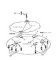
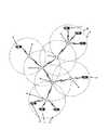
近年の無線ネットワークの発達により、米国電気電子技術者協会(IEEE)が策定した無線LAN(WLAN)規格の1つであるIEEE802.11に準拠した通信システムが普及している。専門家団体であるIEEEの標準化委員会が策定し発表してきた規格群は、システムを効果的かつ効率的に利用するために複数の主体間で手続きの策定を必要とする、通信、電力、コンピューティング、その他多くのシステムの商業効率を高めるものとして国際的に認知されている。ここでの規格とは、図1および2に示すシステムのような無線LANにおいて多様な製造業者による通信装置が相互に接続可能となる、全ての装置ベンダにとって確固としたプロトコルを提供するものである。またデータ規格はIEEE802.11に規定されている。 With the development of wireless networks in recent years, communication systems based on IEEE 802.11, which is one of wireless LAN (WLAN) standards formulated by the Institute of Electrical and Electronics Engineers (IEEE), have become widespread. A group of standards formulated and published by the IEEE Standardization Committee, an expert body, is a communication, power and computing system that requires the development of procedures among multiple entities in order to use systems effectively and efficiently. And many other systems are recognized internationally as enhancing the commercial efficiency of systems. The standard here provides a robust protocol for all device vendors that allows interconnecting communication devices from various manufacturers in a wireless LAN such as the systems shown in FIGS. . The data standard is defined in IEEE 802.11.
無線LANを利用したデータサービスは広範囲にわたるが、リアルタイムで双方向のマルチメディアサービスをサポートするために無線LANを商業的に利用することは稀である。これは主に、現在市場で入手可能なIEEE802.11対応カードの大半が、IEEE802.11に定義される競合型の(Contention-based)メディアアクセス制御(MAC)層の動作モード、すなわち分散制御機能(Distributed Coordination Function:DCF)のみを使用するためである。後述するように、DCFモードはリアルタイムのアプリケーションをサポートする為に使用することができない。IEEEはこの問題について認識していた為、IEEE802.11ではポーリング方式のMAC層の動作モード、すなわち集中制御機能(Point Coordination Function:PCF)も提供されている。 While data services using wireless LANs are widespread, commercial use of wireless LANs to support real-time, interactive multimedia services is rare. This is mainly due to the fact that most of the currently available IEEE 802.11 compliant cards have a contention-based media access control (MAC) layer operating mode defined by IEEE 802.11, ie, a distributed control function. (Distributed Coordination Function: DCF) only. As described below, the DCF mode cannot be used to support real-time applications. Since IEEE has been aware of this problem, IEEE 802.11 also provides an operation mode of a MAC layer of a polling method, that is, a centralized control function (Point Coordination Function: PCF).
IEEE802.11は、IEEE802.11作業部会によって規定された無線アクセス技術の標準規格である。このIEEE802.11は、インフラストラクチャモードとアドホックモードの2つの方式をサポートしている。図2に示すインフラストラクチャモードの場合、移動局(MT)のデータはアソシエーション(関係づけ)されている1つのアクセスポイント(AP)に送信され、受信したAPはこのパケットを適切な宛先に送信する。他方、アドホックモードではMTが互いに直接通信を行う。 IEEE 802.11 is a standard for wireless access technology defined by the IEEE 802.11 working group. This IEEE 802.11 supports two modes, an infrastructure mode and an ad hoc mode. In the case of the infrastructure mode shown in FIG. 2, the data of the mobile station (MT) is transmitted to one associated access point (AP), and the received AP transmits the packet to an appropriate destination. . On the other hand, in the ad hoc mode, MTs communicate directly with each other.
IEEE802.11は、3つの異なる物理層の方式もサポートしている。この3つの物理層とは、周波数ホッピング方式のスペクトラム拡散(Frequency Hopping Spread Spectrum:FHSS)、直接拡散方式のスペクトラム拡散(Direct Sequence Spread Spectrum:DSSS)および赤外線(IR)である。これら3つの物理層によれば、最大11Mbpsのデータ転送速度がサポートされる。さらにデータ転送速度を向上させるために後継規格としてIEEE802.11aが標準化され、このIEEE802.11aは、物理層の変調方式として直交波周波数分割多重(Orthogonal Frequency Divided Multiplexing:OFDM)を使用する。IEEE802.11は、物理層の方式の相違にかかわらずMAC層の規格が共通している為、この形式のメッセージフレームはIEEE802.11が規定する物理層の方式において標準規格となっている。IEEE802.11のMAC層では、DCFモードとPCFモードの2つの動作モードがサポートされている。 IEEE 802.11 also supports three different physical layer schemes. The three physical layers are a frequency hopping type spread spectrum (FHSS), a direct spread type spread spectrum (Direct Sequence Spread Spectrum: DSSS) and an infrared ray (IR). With these three physical layers, a data transfer rate of up to 11 Mbps is supported. In order to further improve the data transfer rate, IEEE 802.11a is standardized as a successor standard, and this IEEE 802.11a uses orthogonal frequency division multiplexing (OFDM) as a modulation method of a physical layer. Since IEEE 802.11 has a common MAC layer standard regardless of the difference in the physical layer system, this type of message frame is a standard in the physical layer system defined by IEEE 802.11. The IEEE 802.11 MAC layer supports two operation modes, a DCF mode and a PCF mode.
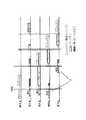
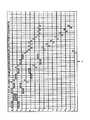
図3に示すように、DCFモードは競合型の動作モードであり、搬送波感知多重アクセス/衝突回避方式(Carrier Sense Multiple Access with Collision Avoidance:CSMA/CA)が用いられる。データを送信する際、MThは無線チャネルをモニターする。チャネルがアイドルである場合でも、直ちにデータを送信せずにDCF Interframe Space(DIFS)pと呼ばれる短い期間送信を遅らせる。DIFSpの間送信を遅らせるとMThは再びチャネルをモニターし、チャネルがアイドルであればパケットを送信する。チャネルがビジーである場合は、再び送信を試みる前にランダムな期間バックオフに入る。各MThが媒体を競合するため、DCFモードは競合型の動作モードと呼ばれる。図3が明示するように、DCFモードで動作するMThはランダムに送信を行っている。その結果、DCFモードで動作するMThには体系的なフレーム範囲が設定されない為、2つの連続するデータ間のジッタを予測することができない。このため、DCFモードは信頼性の高いマルチメディアサービスには本来的に不適当である。 As shown in FIG. 3, the DCF mode is a contention type operation mode, and a carrier sense multiple access with collision avoidance (CSMA / CA) is used. When transmitting data, MTh monitors the radio channel. Even if the channel is idle, it does not immediately transmit data but delays transmission for a short period called DCF Interframe Space (DIFS) p. If the transmission is delayed during DIFSp, MTh monitors the channel again and transmits the packet if the channel is idle. If the channel is busy, it enters backoff for a random period before trying to transmit again. The DCF mode is called a contention-type operation mode because each MTh competes for the medium. As clearly shown in FIG. 3, the MTh operating in the DCF mode transmits at random. As a result, since a systematic frame range is not set for the MTh operating in the DCF mode, the jitter between two consecutive data cannot be predicted. For this reason, DCF mode is inherently unsuitable for reliable multimedia services.
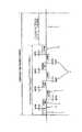
遅延による影響を受けやすい音声等のアプリケーションをサポートする為、IEEE802.11のMAC層には別の動作モードとしてPCFモードがある。図4は、ポーリング方式の動作モードであるPCFモードが用いられるContention-Free Period(CFP)を例示している。任意のAPはデータを送信する前に割り当てられたチャネルをモニターして他の送信が継続中かどうかを調べる。チャネルがアイドルである場合でも、DCFモードと同様に、図5に示すPCF Interframe Space(PIFS)qと呼ばれる短い期間送信を遅らせる。PIFSqの期間はDIFSpの期間よりも短いため、PCFモードで動作するAPは、DCFモードで動作する装置のDIFSpが経過する前に送信を行い、その結果として送信スロットを確保できる。CFPは、IEEEの規格に定義されているCF_Max_Durationパラメータを使用することで設定可能であり、各APは、Contention-Free Repetition Rate(CFRRate)と呼ばれる一定の割合でCFPを設定する。図4に示すように、APはあるCFPの終了から次のCFPの開始まではDCFモードで動作し、この期間をContention Period(CP)rと呼ぶ。そして図6に示すように、CFPとCPrの合計をContention Free Repetition Intervalまたはスーパーフレームと呼ぶ。 In order to support applications such as voice that is susceptible to delay, the MAC layer of IEEE 802.11 has a PCF mode as another operation mode. FIG. 4 illustrates a Contention-Free Period (CFP) in which a PCF mode, which is an operation mode of a polling method, is used. Before transmitting any data, any AP monitors the assigned channel to see if other transmissions are ongoing. Even when the channel is idle, transmission is delayed for a short period called PCF Interframe Space (PIFS) q shown in FIG. 5, as in the DCF mode. Since the period of PIFSq is shorter than the period of DIFSp, the AP operating in the PCF mode performs transmission before the elapse of DIFSp of the device operating in the DCF mode, and as a result, a transmission slot can be secured. The CFP can be set by using the CF_Max_Duration parameter defined in the IEEE standard, and each AP sets the CFP at a fixed rate called a Contention-Free Repetition Rate (CFRRate). As shown in FIG. 4, the AP operates in the DCF mode from the end of one CFP to the start of the next CFP, and this period is called a Contention Period (CP) r. Then, as shown in FIG. 6, the sum of CFP and CPr is called a Contention Free Repetition Interval or a superframe.
各APはポーリングリストを保持し、各CFPの間、CF-Poll+Data sのメッセージフレームを使用してポーリングリスト上の装置に対して少なくとも1回ポーリングを行う。CF-Poll+Data sメッセージを受信したMThは、Data+ACKtのメッセージフレームを使用して受信通知と応答データを送信する。各データフレーム間の期間はShort Interframe Space(SIFS)uと呼ばれ、図5に示すようにDIFSpやPIFSqの期間よりも短い。図4および6に示すように、各CFPの開始時にはビーコンvがTbと定義される間隔で送信される。 Each AP maintains a polling list and polls the devices on the polling list at least once during each CFP using a CF-Poll + Datas message frame. The MTh that has received the CF-Poll + Datas message transmits a reception notification and response data using a Data + ACKt message frame. The period between each data frame is called Short Interframe Space (SIFS) u, and is shorter than the period of DIFSp or PIFSq as shown in FIG. As shown in FIGS. 4 and 6, at the start of each CFP, a beacon v is transmitted at intervals defined as Tb.
CFPが終了する場合は2つある。1番目は、CF_Max_Duration時間が経過した場合である。2番目は、APが、ポーリングリスト上の全てのクライアントに対するポーリングを行った後にCF_END wメッセージを送信した場合である。PCFモードは上述したような遅延期間を使用してコネクション指向型のサービスを提供するため、マルチメディアサービスをサポートする。 There are two cases where the CFP ends. The first case is when the CF_Max_Duration time has elapsed. Second, the AP sends a CF_END w message after polling all clients on the polling list. The PCF mode supports a multimedia service in order to provide a connection-oriented service using the above-described delay period.
マルチホップネットワークは、ノードが、送信過程が開始する中心ノードの通信範囲外の他のノードへ情報パケットを中継することでネットワークのカバーエリアを拡張する無線ネットワークの一種である。IEEE802.11に準拠したマルチホップネットワークの利用には実社会上の利点がある。例えば、携帯電話は病院の医療機器の動作を妨害するため病院では使用が禁止されているが、IEEE802.11に準拠した装置であれば医療機器の動作を妨害することはない。従って、IEEE802.11準拠の無線LANを利用して音声サービスを提供することは有意義であり、マルチホップネットワークを利用することによりカバーエリアが拡張されることになる。しかしながら、IEEE802.11で標準化されているPCFモードを単純に使用した場合には、マルチホップネットワークを介した音声サービスがサポートされない。このトピックについてはIEEE802.11でより詳細に扱われている。従って、改良されたマルチホップサービスを可能にするように無線LANプロトコルを改良する必要がある。 A multi-hop network is a type of wireless network in which a node extends the network coverage area by relaying information packets to other nodes outside the communication range of a central node where the transmission process starts. The use of a multi-hop network based on IEEE 802.11 has real-world advantages. For example, mobile phones are prohibited from being used in hospitals because they interfere with the operation of medical equipment in hospitals. However, devices that comply with IEEE 802.11 do not interfere with the operation of medical equipment. Therefore, it is meaningful to provide a voice service using an IEEE802.11 compliant wireless LAN, and the coverage area is expanded by using a multi-hop network. However, simply using the PCF mode standardized by IEEE 802.11 does not support voice services via a multi-hop network. This topic is covered in more detail in IEEE 802.11. Therefore, there is a need to improve wireless LAN protocols to allow for improved multi-hop services.
従来技術の問題点を解決するために、本発明は、通信伝送フレームプロトコルとその方法を提供することを目的としている。これによれば、IEEE802.11に準拠したAPおよびMTや、図1および2に示すシステム上で動作するように設計されたAPおよびMT間の送信の衝突または干渉を回避することができる。上述したように、各APが範囲指定された期間に送信を行うのでなければ、特にマルチホップ無線LANではAPによる競合する送信間の干渉を回避することはできない。期間が適切に範囲指定されれば、APは、他のAPによる干渉を受けずにそのクライアントに対して集中制御者(Point Coordinator:PC)として機能する。また本発明は、802.11に主に準拠した(この規格に限定されるわけではない)、スケジュール情報や範囲情報を提供しマルチホップ型のリアルタイム通信を可能にする新しいメッセージフレームを提供する。このメッセージフレームには、APが自身のクライアントであるローカルアクセスポイント(LAP)やMTへ情報を送信する期間を定義するスケジューリング情報パラメータセット(Scheduling Information Parameter Set:SIPS)ddが含まれている。 In order to solve the problems of the prior art, an object of the present invention is to provide a communication transmission frame protocol and a method thereof. According to this, it is possible to avoid transmission collision or interference between the AP and MT compliant with IEEE802.11 and the AP and MT designed to operate on the systems shown in FIGS. As described above, interference between competing transmissions by APs cannot be avoided, especially in a multi-hop wireless LAN, unless each AP transmits during a period specified in a range. If the time period is appropriately specified, the AP functions as a point coordinator (PC) for the client without interference from other APs. In addition, the present invention provides a new message frame that mainly conforms to (but is not limited to) this standard, provides schedule information and range information, and enables multi-hop real-time communication. This message frame includes a scheduling information parameter set (SIPS) dd that defines a period during which the AP transmits information to a local access point (LAP) or MT, which is its own client.
SIPSddにはAPの送信時間を設定する3つの異なる値が含まれている。第1の値であるオフセット時間は、送信中のAP、すなわちPCと深度が同じAPが、クライアントであるLAPに対するポーリングを完了ための時間である。第2の値である遅延時間は、受信LAPがそのクライアントに対してPCとしての機能を開始するまでの時間である。第3の値であるインターバル時間は、受信LAPがPCとして機能する時間である。以上のパラメータが指定されることで、受信LAPはPCとして機能する時間範囲を判断する。 SIPSdd contains three different values that set the AP transmission time. The first value, the offset time, is the time for the transmitting AP, that is, the AP having the same depth as the PC, to complete the polling for the LAP serving as the client. The delay time, which is the second value, is the time until the receiving LAP starts functioning as a PC for the client. The interval time, which is the third value, is the time during which the receiving LAP functions as a PC. By specifying the above parameters, the receiving LAP determines a time range in which it functions as a PC.
全てのLAPがそれぞれに割り当てられた時間フレームを知っていれば、他のLAPとの送信の衝突や干渉は起こらないはずである。この通信プロトコルは、LAPが時間フレームを競合することなくデータを送信しクライアントにポーリングを行うためのスケジューリング情報を用いており、IEEE802.11が規定するCFPのポーリングを改良するものである。従って、この通信プロトコルは、マルチホップ型無線LANにおける双方向メディアや音声通信に容易に応用可能である。例えば、携帯電話通信ネットワークは、通信ケーブルや光ファイバの架線が経済的に見合わない山岳地帯や険しい地形等でマルチホップネットワークとして動作してもよい。本発明のその他の方法、システム、特徴および利点は、本明細書に添付の図面と発明を実施するための最良の形態の説明により当業者にとって明らかになるであろう。 If all LAPs know their assigned time frames, then transmission collisions and interference with other LAPs should not occur. This communication protocol uses scheduling information for the LAP to transmit data and poll clients without competing for time frames, and improves the CFP polling defined by IEEE 802.11. Therefore, this communication protocol can be easily applied to two-way media and voice communication in a multi-hop wireless LAN. For example, a cellular telephone communication network may operate as a multi-hop network in mountainous areas, on steep terrain, or the like where communication cables or optical fiber overhead lines are not economically justified. Other methods, systems, features and advantages of the invention will be or become apparent to one with skill in the art upon examination of the drawings and description of the best mode for carrying out the invention.
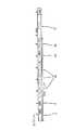
図1および2は、上述のIEEE802.11に準拠した通信データフレームを使用するシステムを示している。ゲートウェイアクセスポイント(GAP)aは、有線インターネットに直接接続する主要アクセスポイントである。LAPb、c、d、e、fおよびgは、有線インターネットに直接接続せずにGAPaを介して無線ネットワーク接続する。当該システムに含まれる各LAPやノードは、IEEE802.11に準拠して動作可能であり1つのチャネルを使用して送受信を行う。 1 and 2 show a system that uses the above-mentioned IEEE 802.11-compliant communication data frame. The gateway access point (GAP) a is a main access point that connects directly to the wired Internet. LAPs b, c, d, e, f, and g do not connect directly to the wired Internet, but connect to a wireless network via GAPa. Each LAP or node included in the system is operable according to IEEE 802.11, and performs transmission and reception using one channel.
図2において、GAPaは有線インターネットに直接接続するアクセスポイントである。図2に示す具体的な実施形態は、システムがツリー構造をとる無線マルチホップネットワークを形成する。当該ネットワークに代わるものとして、別の構成や変形例が考えられることは想定されており、これらは本発明の範囲に含まれる。本実施形態の配置では、いくつかのLAPがGAPaと直接通信可能な範囲外にある。LAPe、fおよびgはGAPaから離れたホップであり、所定の深度のLAPには深度番号が割り当てられる。この番号は、深度番号1であるGAPaを起点として割り当てられる。従って、GAPaのすぐ下流に隣接するLAPの深度番号は2となり、GAPaから2番目のLAPであるLAPb、cおよびdがこれに該当する。この実施形態では、深度番号が2である任意のLAPにとって最も隣接する上流のLAPはGAPaである。LAPbにとって最も隣接する下流のLAPはLAPeおよびfであり、LAPeおよびfには深度番号3が割り当てられる。尚、この実施形態では、LAPcにとって下流のLAPはLAPgのみであり、LAPdには下流のLAPが存在しない。従って、図2に示すようなツリー構造の場合、任意のLAPに対して上流のLAPは1つだけ存在し、下流のLAPについては複数存在する場合と存在しない場合とがある。 In FIG. 2, GAPa is an access point directly connected to the wired Internet. The specific embodiment shown in FIG. 2 forms a wireless multi-hop network in which the system takes a tree structure. It is envisioned that other configurations and modifications may be considered as alternatives to the network, and these are included in the scope of the present invention. In the arrangement of the present embodiment, some LAPs are outside the range that can directly communicate with GAPa. LAPe, f and g are hops away from GAPa, and a LAP having a predetermined depth is assigned a depth number. This number is assigned starting from GAPa which is depth number 1. Therefore, the depth number of the LAP immediately adjacent to GAPa is 2, and LAPb, c, and d, which are the second LAP from GAPa, correspond to this. In this embodiment, the upstream LAP closest to any LAP with a depth number of 2 is GAPa. The downstream LAPs closest to LAPb are LAPE and f, and LAPe and f are assigned depth number 3. In this embodiment, the only LAP downstream of LAPc is LAPg, and no downstream LAP exists in LAPd. Therefore, in the case of the tree structure as shown in FIG. 2, there is only one upstream LAP with respect to an arbitrary LAP, and there may be a case where a plurality of downstream LAPs exist and a case where there is no such LAP.
上述したように、1度に1つのAPのみが送信を行うのでなければ、2またはそれ以上の送信ユニット間で送信の衝突が起こる。これは、各ユニットが送信部と受信部を1つずつ有し、これら両方が単一のチャネルを使用するためである。無線干渉範囲内にある2つのユニットが同時に単一のチャネルでPCFを利用する場合、どちらかのPCFが終了するまで常に送信が衝突してしまう。従って、本実施形態では、双方向データの送信や音声通信の体系的な方法を提供するために、LAPb、c、d、e、fおよびgの役割がPCの役割とLAPの役割の間で周期的に変化する。将来の実施形態では、APが送信部や受信部を複数使用することによって、単一の周波数帯域やチャネルを使用して送信する必要がなくなるかもしれない。マルチチャネル送信が可能な送信部を想定した将来の実施形態も予想されているが、この実施形態でも本発明を利用することができる。従って、この通信プロトコルを実装して複数のチャネルで送信スロットを範囲指定することにより、マルチホップシステムの帯域幅を増やしてもよい。 As mentioned above, unless only one AP is transmitting at a time, a transmission collision occurs between two or more transmitting units. This is because each unit has one transmitter and one receiver, both of which use a single channel. If two units within the radio interference range simultaneously use the PCF on a single channel, the transmission will always collide until one of the PCFs ends. Therefore, in this embodiment, the roles of LAPb, c, d, e, f and g are switched between the role of PC and the role of LAP in order to provide a systematic method of two-way data transmission and voice communication. It changes periodically. In future embodiments, the use of multiple transmitters and receivers by the AP may eliminate the need to transmit using a single frequency band or channel. Although a future embodiment assuming a transmission unit capable of multi-channel transmission is expected, the present invention can also be used in this embodiment. Therefore, the bandwidth of a multi-hop system may be increased by implementing this communication protocol and specifying the transmission slots in a plurality of channels.
LAPは、競合する送信の干渉を回避するために所定の時間だけ送信を遅らせる。この遅延が適切に予定されると、通信フレーム内でPCとして機能する時間が各LAP毎に設定されることになる。このために、LAPb、c、d、e、fおよびgには、個々の送信時間を決定するための種々のパラメータ値が与えられる。その結果の一例として、図7に示すような任意の送信順序xがある。設計者の要求次第で他の送信順序も可能であるが、これらについても本発明において考慮されている。 LAP delays transmission by a predetermined amount of time to avoid interference with competing transmissions. If this delay is properly scheduled, the time to function as a PC in a communication frame will be set for each LAP. For this purpose, LAPb, c, d, e, f and g are given various parameter values for determining the individual transmission times. As an example of the result, there is an arbitrary transmission order x as shown in FIG. Other transmission orders are possible depending on the requirements of the designer, but these are also considered in the present invention.
IEEE802.11では、CF-Poll+Data sメッセージを使用して各クライアントに対するポーリングが行われ、このデータフレームは図8に示すように構成される。データフレームを構成するMACヘッダは、フレーム制御ブロックy、期間ブロックz、複数のメッセージ宛先ブロックaaおよびシーケンス制御ブロックbbからなる。そしてMACヘッダのすぐ後に続くのは、このヘッダに関連付けらた情報データccである。図4に示すように、クライアントであるLAPは、CF-Poll+Data sメッセージを受信すると受信通知と応答データを送信する。しかしながら、クライアントである各LAPの他の送信時間が予定されていない為、無線LANシステムで利用する送信時間に関する情報を含むように既存のCF-Poll+Data sメッセージフレームを変更する。新しいデータフレームは"CF-Poll+Data+SIPS"と呼ばれ、SIPSddを含んでいるという点で標準規格のCF-Poll+Data sメッセージと異なっている。CF-Poll+Data+SIPSのメッセージフレームは図9に示すように構成される。 In IEEE 802.11, polling for each client is performed using a CF-Poll + Datas message, and this data frame is configured as shown in FIG. The MAC header constituting the data frame includes a frame control block y, a period block z, a plurality of message destination blocks aa, and a sequence control block bb. Immediately following the MAC header is the information data cc associated with this header. As shown in FIG. 4, upon receiving the CF-Poll + Datas message, the LAP that is the client transmits a reception notification and response data. However, since the transmission time of each LAP as a client is not scheduled, the existing CF-Poll + Datas message frame is changed to include information on the transmission time used in the wireless LAN system. The new data frame is called "CF-Poll + Data + SIPS" and differs from the standard CF-Poll + Datas message in that it contains SIPSdd. The message frame of CF-Poll + Data + SIPS is configured as shown in FIG.
上述したメッセージフレームのSIPSdd部分が規定するLAPb、c、d、e、fおよびgそれぞれの時間範囲情報によって、各LAPは通信フレーム内においてPCとして機能を開始する時間とその期間を決定する。このため、図10に示すようにSIPSddには3つのフィールドがある。第1のフィールドであるオフセットeeフィールドは、上流のLAPが、同じ深度のクライアントLAPに残り全てのデータ送信するのに要する時間を指定する。第2のフィールドである遅延ffフィールドは、上流のLAPがPCとしての機能を完了後に受信LAPが送信を遅延する時間を指定する。これには、同じ深度のLAPのうち最初にPCとして機能するLAPが自身の全クライアントLAPと通信を行うために要する時間も含まれる。本実施形態では、最初にLAPbが送信を行い、次にLAPcが送信を行い、最後にLAPdが送信を行う。第3のフィールドであるインターバルggフィールドは、LAPがPCとして機能する期間を指定する。LAPはインターバルggフィールドに指定された時間と等しいCF_Max_Durationを設定し、その値はポーリングを行うクライアントLAPの数によって決まる。 Based on the time range information of each of the LAPs b, c, d, e, f, and g defined by the SIPSdd portion of the message frame described above, each LAP determines a time when the function starts as a PC in the communication frame and a period thereof. Therefore, as shown in FIG. 10, SIPSdd has three fields. The first field, the offset ee field, specifies the time required for the upstream LAP to transmit all remaining data to the same depth client LAP. The second field, the delay ff field, specifies how long the receiving LAP delays transmission after the upstream LAP has completed its function as a PC. This includes the time required for the first LAP of the same depth to function as a PC to communicate with all its client LAPs. In the present embodiment, LAPb performs transmission first, then LAPc performs transmission, and finally LAPd performs transmission. The third field, the interval gg field, specifies the period during which the LAP functions as a PC. The LAP sets CF_Max_Duration equal to the time specified in the interval gg field, and its value is determined by the number of client LAPs that perform polling.
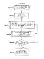
GAPaからクライアントLAPb、c、d、e、fおよびgへデータを中継するために、図7に示すような任意のスケジューリングプロトコルが用いられる。全てのクライアントLAPに対してポーリングが行われるのであれば、その順序は問わない。図2では、GAPaが最初にPCとして機能し、GAPaのクライアントである下流のLAPb、cおよびdとデータの送受信を行う。図11のフローチャートに示すように、GAPaは初めにビーコンvを送出して(ステップ100)PCとして機能することをLAPに知らせる。GAPaは、SIPSddの要素(オフセットee、遅延ffおよびインターバルgg)の値を0に初期化すると(ステップ102)、SIPSddの要素の値を最初の受信LAP(この例ではLAPb)用に設定し(ステップ104)、CF-Poll+Data+SIPSをLAPbに送信する(ステップ106)。LAPbから受信通知を受信すると、GAPaはポーリングを行うべきLAP(この例ではLAPcおよびd)がさらに2つ存在することを確認し(ステップ108)、残り全てのLAPに対してポーリングを行うまで同様の動作(ステップ104、106および108)を繰り返す。全てのクライアントLAPに対してポーリングを行うと、GAPaはCF_END wを送信してPCとしての役割を終了する(ステップ110)。 To relay data from GAPa to clients LAPb, c, d, e, f and g, any scheduling protocol as shown in FIG. 7 is used. As long as polling is performed for all the client LAPs, the order does not matter. In FIG. 2, GAPa first functions as a PC, and transmits and receives data to and from downstream LAPs b, c, and d that are clients of GAPa. As shown in the flowchart of FIG. 11, GAPa first transmits a beacon v (step 100) to inform the LAP that it will function as a PC. When GAPa initializes the values of the SIPSdd elements (offset ee, delay ff, and interval gg) to 0 (step 102), it sets the values of the SIPSdd elements for the first received LAP (LAPb in this example) ( Step 104), and sends CF-Poll + Data + SIPS to LAPb (Step 106). Upon receiving the reception notification from LAPb, GAPa confirms that there are two more LAPs to be polled (LAPc and d in this example) (step 108), and repeats until all the remaining LAPs are polled. (
GAPaがPCとして機能している間、各LAPb、c、d、e、fおよびgはPCであるGAPaからのメッセージをモニターする。ここで、図12のフローチャートを参照してLAPbの動作について説明する。各LAPはGAPaにポーリングされまでは何もせず、自身のアドレスに対応するCF-Poll+Data+SIPSを受信すると、しかるべきデータと受信通知をGAPaに対して返信する(ステップ200)。受信LAPのソフトウェアルーチンは、当該メッセージのSIPSddの情報を利用してタイムアウトを遅延ffとオフセットeeを合計した値に設定し、CF_Max_Durationをインターバルggの値に設定する(ステップ202)。CF_END wを受信していない場合(ステップ204)、LAPbはメッセージのモニターを継続して上記の動作を再び開始する(ステップ200)。CF_END wを受信した場合、タイマが、LAPbがPCとしての機能を開始する時期のカウントダウンを開始する(ステップ206)。このタイマはDCFモードの期間を決定する。 While GAPa is functioning as a PC, each LAPb, c, d, e, f and g monitors messages from the PC, GAPa. Here, the operation of LAPb will be described with reference to the flowchart of FIG. Each LAP does nothing when polled by GAPa, and upon receiving CF-Poll + Data + SIPS corresponding to its own address, returns appropriate data and a reception notification to GAPa (step 200). The software routine of the receiving LAP sets the timeout to a value obtained by adding the delay ff and the offset ee using the information of the SIPSdd of the message, and sets CF_Max_Duration to the value of the interval gg (step 202). If CF_END w has not been received (step 204), LAPb continues to monitor the message and starts the above operation again (step 200). If CF_END w is received, the timer starts counting down when LAPb starts functioning as a PC (step 206). This timer determines the duration of the DCF mode.
タイマの設定時間が経過すると、LAPbは自身がPCとして機能することを知らせるビーコンvを送信する(ステップ210)。LAPbは遅延ffとインターバルggの値を0に初期化し、これらの値を最初のクライアントLAP(この例ではLAPe)用に設定する(ステップ212)。LAPbはこのメッセージをLAPeに送信してLAPeから受信通知を受信する(ステップ214)。LAPbは他にポーリングを行うべきLAPが存在するかどうかを判断し(ステップ216)、残り全てのLAPに対してポーリングを行うまで同様の動作を繰り返す。この例では、LAPfが他にポーリングを行うべきLAPに該当する。LAPbは、LAPfにポーリングを行うと自身の送信期間が終了することを知らせるCF_END wメッセージを送信する(ステップ218)。送信期間についてはインターバル時間ggに予め設定されており、送信時間が終了するタイミングについても予め設定されているため、ポーリングは予定通りに終了する。LAPcは、LAPbがクライアントLAPとの通信を終了するのを待ってから図12のフローチャートに示す動作を開始し、LAPdはLAPbおよびcがクライアントLAPに対するポーリングを終了するのを待つ。 When the set time of the timer elapses, LAPb transmits a beacon v indicating that it functions as a PC (step 210). LAPb initializes the values of delay ff and interval gg to 0, and sets these values for the first client LAP (LAPe in this example) (step 212). LAPb transmits this message to LAPe and receives a reception notification from LAPe (step 214). LAPb determines whether there is another LAP to be polled (step 216), and repeats the same operation until polling all the remaining LAPs. In this example, LAPf corresponds to another LAP to be polled. When LAPb polls LAPf, it sends a CF_END w message notifying that its transmission period has ended (step 218). The transmission period is set in advance to the interval time gg, and the timing at which the transmission time ends is also set in advance, so that the polling ends as scheduled. LAPc starts the operation shown in the flowchart of FIG. 12 after waiting for LAPb to end communication with the client LAP, and LAPd waits for LAPb and c to finish polling the client LAP.
送信時間枠が適切に範囲指定されることで、AP間の送信の衝突や干渉が起こらないのである。本発明が提供するプロトコルでは、PCFを行うPCが常に1つだけ存在するようになっている。CF-Poll+Data+SIPSのデータフレームは、図8に示すIEEE802.11のPCFで使用されるデータフレームと類似している。しかしながら、本発明のシステムと従来技術との相違点により、CF-Poll+Data+SIPSを使用してポーリングされたクライアントLAPは、SIPSddのオフセットeeフィールド、遅延ffフィールド、インターバルggフィールドの各種の値によって決定される時間にPCとして下流のクライアントLAPに対する送信を行う。 By appropriately specifying the range of the transmission time frame, transmission collision and interference between APs do not occur. In the protocol provided by the present invention, there is always only one PC that performs PCF. The data frame of CF-Poll + Data + SIPS is similar to the data frame used in the IEEE 802.11 PCF shown in FIG. However, due to the difference between the system of the present invention and the prior art, the client LAP polled using CF-Poll + Data + SIPS has various values of the SIPSdd offset ee field, delay ff field, and interval gg field. Is transmitted to the downstream client LAP as a PC at the time determined by.
第2実施形態では、送信タイミングを設定する別の方法について説明する。例えば、GAPaがまずLAPbにポーリングを行い次にLAPcにポーリングを行う場合、LAPc用に設定される遅延ffは、LAPbが自身のクライアントLAP全てにポーリングできるように設定される。本実施形態について図13を参照して説明する。LAPb、c、d、e、fおよびgが行うモニターについては、図12に示すステップ200〜208と同様である。LAPb、c、d、e、fおよびgはPCとしての機能を開始すると、ビーコンvを送信し(ステップ310)、SIPSddフィールドの要素(オフセットee、遅延ffおよびインターバルgg)の値を初期化する(ステップ312)。この例においてLAPbが現在PCとして機能していると仮定すると、LAPbは遅延ffフィールドとインターバルggフィールドにしかるべき値を設定する。尚、オフセットeeフィールドの値は0に初期化されたままである。 In the second embodiment, another method for setting the transmission timing will be described. For example, if GAPa polls LAPb first and then LAPc, then the delay ff set for LAPc is set so that LAPb can poll all of its client LAPs. This embodiment will be described with reference to FIG. The monitoring performed by LAPs b, c, d, e, f, and g is the same as
この例においてLAPbによってポーリングされるクライアントがLAPeそしてfであるとさらに仮定すると、LAPf用に設定される遅延ffフィールドとインターバルggフィールドの値は、LAPeがそのクライアント全てにポーリングできるように設定される。LAPbは、遅延ffの値を0に設定したCF-Poll+Data+SIPSをLAPeに送信する。遅延ffの値が0に設定されている為、LAPeはCF_END wを受信すると遅滞なくPCとしての機能を開始する。LAPbはData+ACKtを受信すると(ステップ316)、他にポーリングを行うべきLAPが存在するかどうかを判断し(ステップ318)、ポーリングリスト上の全ての装置に対してポーリングを行う。この例では、LAPfが他にポーリングを行うべきLAPに該当する。LAPfは、遅延ffに設定された値に従い、LAPeがそのクライアント全てに対するポーリングを完了するまで送信を遅延させる。 Further assuming that the clients polled by LAPb in this example are LApe and f, the values of the delay ff and interval gg fields set for LAPf are set so that LAPe can poll all of its clients. . LAPb transmits CF-Poll + Data + SIPS with the value of delay ff set to 0 to LAPe. Since the value of the delay ff is set to 0, LAPe starts the function as a PC without delay when CF_END w is received. When LAPb receives Data + ACKt (step 316), it determines whether there is another LAP to be polled (step 318) and polls all devices on the polling list. In this example, LAPf corresponds to another LAP to be polled. LAPf delays transmission according to the value set for delay ff until LAPe completes polling all its clients.
本発明に係る方法はソフトウェアプログラムコードや、当該プログラムコードを記録したコンピュータ読み取り可能な記録媒体として実現されてもよい。また、本発明に係る方法は上記ソフトウェアプログラムコードをエンコードした電気信号として実現され、この電気信号は有線または無線通信網を介して送受信されてもよい。 The method according to the present invention may be implemented as a software program code or a computer-readable recording medium recording the program code. Further, the method according to the present invention may be implemented as an electric signal that encodes the software program code, and the electric signal may be transmitted and received via a wired or wireless communication network.
以上説明してきた実施形態は、既存のデータネットワークのみならず双方向メディアや音声通信システムにも応用可能である。例えば、病院内のネットワークは、本発明のシステムを利用することによって、静脈部や心臓部のパラメータを遠隔的に調節する医療機器と相互に情報をやり取りすることが可能になる。IEEE802.11では、FHSS、DSSSおよびIR等の物理層の方式の相違にかかわらずMAC層の規格が共通しているため、本明細書で説明したメッセージフレームのフォーマットはこれら全ての方式で利用することができる。以上、本発明の様々な実施形態について説明してきたが、本発明の範囲から逸脱することなくさらに別の実施形態や実施方法が可能であることは当業者にとって明白である。 The embodiments described above are applicable not only to existing data networks but also to interactive media and voice communication systems. For example, a hospital network can use the system of the present invention to interact with medical devices that remotely adjust venous and cardiac parameters. In IEEE 802.11, the standard of the MAC layer is common irrespective of the difference of the physical layer system such as FHSS, DSSS, and IR, so the message frame format described in this specification is used in all of these systems. be able to. While various embodiments of the present invention have been described above, it will be apparent to those skilled in the art that further embodiments and implementation methods are possible without departing from the scope of the present invention.
a…GAP、b、c、d、e、fおよびg…LAP、h、i、j、k、l、m、nおよびo…MT、p…DIFS、q…PIFS、r…CP、s…CF-Poll+Data、t…Data+ACK、u…SIFS、v…ビーコン、w…CF_END、x…任意の送信順序、y…フレーム制御ブロック、z…期間ブロック、aa…メッセージ宛先ブロック、bb…シーケンス制御ブロック、cc…情報データ、dd…SIPS、ee…オフセット、ff…遅延、gg…インターバルa ... GAP, b, c, d, e, f and g ... LAP, h, i, j, k, l, m, n and o ... MT, p ... DIFS, q ... PIFS, r ... CP, s ... CF-Poll + Data, t ... Data + ACK, u ... SIFS, v ... beacon, w ... CF_END, x ... arbitrary transmission order, y ... frame control block, z ... period block, aa ... message destination block, bb ... Sequence control block, cc: information data, dd: SIPS, ee: offset, ff: delay, gg: interval
Claims (2)
Translated fromJapanese通信制御情報を含むメディアアクセス制御ヘッダと、
前記メディアアクセス制御ヘッダに関連付けられた情報データを含むデータブロックセットと、
オフセットフィールド、遅延フィールドおよびインターバルフィールドを含み、前記メディアアクセス制御ヘッダと前記データブロックセットに関連付けられたスケジューリング情報パラメータセットと
を具備することを特徴とする無線LANプロトコル。Using a data frame format of CF-Poll + Data + SIPS, a wireless LAN protocol supporting information packet communication in a wireless LAN, wherein the CF-Poll + Data + SIPS data frame format is
A media access control header including communication control information;
A data block set including information data associated with the media access control header;
A wireless LAN protocol, comprising: an offset field, a delay field, and an interval field, comprising: the media access control header and a scheduling information parameter set associated with the data block set.
メディアアクセス制御ヘッダを使用して通信を制御するステップと、
前記メディアアクセス制御ヘッダに関連付けられたデータブロックセット内のデータ情報を通信するステップと、
オフセットフィールド、遅延フィールドおよびインターバルフィールドを含み、前記メディアアクセス制御ヘッダと前記データブロックセットに関連付けられたスケジューリング情報パラメータセットを使用して、前記ローカルアクセスポイントが集中制御者として機能する時間を予め定めるステップと
を具備することを特徴とする通信方法。In a wireless LAN that transmits information packets using the CF-Poll + Data + SIPS data frame format to a local access point, which is a client, while a gateway access point connected to a wired network functions as a centralized controller A communication method,
Controlling communication using a media access control header;
Communicating data information in a data block set associated with the media access control header;
Using the media access control header and a set of scheduling information parameters associated with the set of data blocks, including an offset field, a delay field and an interval field, to predetermine a time at which the local access point will function as a centralized controller A communication method, comprising:
Applications Claiming Priority (1)
| Application Number | Priority Date | Filing Date | Title |
|---|---|---|---|
| US10/307,701US7356010B2 (en) | 2002-12-02 | 2002-12-02 | Point coordinator control passing scheme using a scheduling information parameter set for an IEEE 802.11 wireless local area network |
Publications (3)
| Publication Number | Publication Date |
|---|---|
| JP2004187297Atrue JP2004187297A (en) | 2004-07-02 |
| JP2004187297A5 JP2004187297A5 (en) | 2007-01-18 |
| JP4266159B2 JP4266159B2 (en) | 2009-05-20 |
Family
ID=32392626
Family Applications (1)
| Application Number | Title | Priority Date | Filing Date |
|---|---|---|---|
| JP2003403632AExpired - Fee RelatedJP4266159B2 (en) | 2002-12-02 | 2003-12-02 | Method for transferring centralized controller using scheduling information parameter set for wireless LAN based on IEEE 802.11 |
Country Status (2)
| Country | Link |
|---|---|
| US (1) | US7356010B2 (en) |
| JP (1) | JP4266159B2 (en) |
Cited By (6)
| Publication number | Priority date | Publication date | Assignee | Title |
|---|---|---|---|---|
| JP2007251667A (en)* | 2006-03-16 | 2007-09-27 | Nec Corp | Radio communication system, radio base station, radio communication terminal, radio communication method, and program of radio communication system |
| US7653346B2 (en) | 2005-03-04 | 2010-01-26 | Sony Corporation | Communication terminal device, communication system, communication method, and program |
| US7869829B2 (en) | 2006-03-16 | 2011-01-11 | Nec Infrontia Corporation | Radio communication system, including a plurality of radio base stations, radio base station, radio communication method, and computer readable medium for radio communication system |
| JP4834098B2 (en)* | 2005-09-16 | 2011-12-07 | 株式会社エヌ・ティ・ティ・ドコモ | Method for improving capacity in multi-hop wireless mesh networks |
| JP2012070444A (en)* | 2004-08-12 | 2012-04-05 | Interdigital Technology Corp | Method and system for controlling access to wireless communication medium |
| US11991731B2 (en) | 2019-02-20 | 2024-05-21 | Mitsubishi Electric Corporation | Wireless station, data aggregation station, wireless system, transmission control method for wireless station, transmission control method for data aggregation, control circuit, and non-transitory storage medium |
Families Citing this family (38)
| Publication number | Priority date | Publication date | Assignee | Title |
|---|---|---|---|---|
| US7606208B2 (en)* | 2002-12-09 | 2009-10-20 | Avaya Inc. | Distributed architecture for deploying multiple wireless local-area networks |
| US7693085B2 (en)* | 2002-12-16 | 2010-04-06 | Avaya Inc. | Traffic specifications for polling requests of periodic sources |
| US7693117B2 (en)* | 2002-12-16 | 2010-04-06 | Avaya Inc. | Power-saving mechanism for periodic traffic streams in wireless local-area networks |
| US7613160B2 (en)* | 2002-12-24 | 2009-11-03 | Intel Corporation | Method and apparatus to establish communication with wireless communication networks |
| ATE383702T1 (en)* | 2003-01-10 | 2008-01-15 | Matsushita Electric Industrial Co Ltd | METHOD FOR SENDING A DATA STREAM OVER A WIRELESS MEDIUM OVER A WIRELESS NETWORK AND WIRELESS NETWORK |
| US7349378B2 (en)* | 2003-02-24 | 2008-03-25 | Toshiba America Research, Inc. | Local area network resource manager |
| US7336642B2 (en)* | 2003-08-07 | 2008-02-26 | Skypilot Networks, Inc. | Communication protocol for a wireless mesh architecture |
| KR100542348B1 (en)* | 2003-09-03 | 2006-01-10 | 삼성전자주식회사 | Method and apparatus for reducing power in wireless lan system |
| US8090857B2 (en) | 2003-11-24 | 2012-01-03 | Qualcomm Atheros, Inc. | Medium access control layer that encapsulates data from a plurality of received data units into a plurality of independently transmittable blocks |
| US7496081B2 (en)* | 2004-05-05 | 2009-02-24 | Nokia Corporation | Adaptive beacon period in a distributed network |
| US7890116B2 (en)* | 2004-05-05 | 2011-02-15 | Nokia Corporation | Adaptive beacon period in a distributed network |
| US20060133394A1 (en)* | 2004-12-21 | 2006-06-22 | Ware Christopher G | Methods of wireless backhaul in a multi-tier WLAN |
| US8934416B2 (en)* | 2005-03-09 | 2015-01-13 | Xirrus, Inc. | System for allocating channels in a multi-radio wireless LAN array |
| JP4579742B2 (en)* | 2005-03-30 | 2010-11-10 | キヤノン株式会社 | Wireless terminal device, wireless communication method, and computer program |
| US7508834B2 (en)* | 2005-06-21 | 2009-03-24 | Current Technologies, Llc | Wireless link for power line communications system |
| US7720471B2 (en)* | 2005-07-27 | 2010-05-18 | Sharp Laboratories Of America | Method for managing hidden stations in a centrally controlled network |
| US8175190B2 (en) | 2005-07-27 | 2012-05-08 | Qualcomm Atheros, Inc. | Managing spectra of modulated signals in a communication network |
| US8509442B2 (en)* | 2005-07-27 | 2013-08-13 | Sharp Laboratories Of America, Inc. | Association, authentication, and security in a network |
| US7848306B2 (en)* | 2005-07-27 | 2010-12-07 | Sharp Laboratories Of America, Inc. | Coexistence of access provider and in-home networks |
| US7856008B2 (en) | 2005-07-27 | 2010-12-21 | Sharp Laboratories Of America, Inc. | Synchronizing channel sharing with neighboring networks |
| US20070058659A1 (en)* | 2005-07-27 | 2007-03-15 | Ayyagari Deepak V | Method for providing requested quality of service |
| US8027345B2 (en)* | 2005-07-27 | 2011-09-27 | Sharp Laboratories Of America, Inc. | Method for automatically providing quality of service |
| US9088907B2 (en)* | 2007-06-18 | 2015-07-21 | Xirrus, Inc. | Node fault identification in wireless LAN access points |
| US8208392B2 (en)* | 2007-08-13 | 2012-06-26 | Samsung Electronics Co., Ltd. | System and method for peer-to-peer beam discovery and communication in infrastructure based wireless networks using directional antennas |
| US8917675B2 (en)* | 2007-08-20 | 2014-12-23 | Samsung Electronics Co., Ltd. | System and method for multiple contention access periods |
| US8817676B2 (en)* | 2008-11-03 | 2014-08-26 | Samsung Electronics Co., Ltd. | Method and system for station-to-station directional wireless communication |
| US8482478B2 (en)* | 2008-11-12 | 2013-07-09 | Xirrus, Inc. | MIMO antenna system |
| US8385362B2 (en)* | 2009-01-09 | 2013-02-26 | Samsung Electronics Co., Ltd. | Method and system for contention-based medium access schemes for directional wireless transmission with asymmetric antenna system (AAS) in wireless communication systems |
| KR20110068555A (en)* | 2009-12-16 | 2011-06-22 | 주식회사 씨엘엘씨디 | B―CDDA-based relay transmission system for wireless mobile internet communication |
| US8687546B2 (en) | 2009-12-28 | 2014-04-01 | Intel Corporation | Efficient uplink SDMA operation |
| US8830854B2 (en) | 2011-07-28 | 2014-09-09 | Xirrus, Inc. | System and method for managing parallel processing of network packets in a wireless access device |
| US8868002B2 (en) | 2011-08-31 | 2014-10-21 | Xirrus, Inc. | System and method for conducting wireless site surveys |
| US9055450B2 (en) | 2011-09-23 | 2015-06-09 | Xirrus, Inc. | System and method for determining the location of a station in a wireless environment |
| US9749974B2 (en)* | 2013-01-16 | 2017-08-29 | Intel IP Corporation | Methods and arrangements for frame transmissions |
| WO2015054859A1 (en) | 2013-10-17 | 2015-04-23 | 华为技术有限公司 | User data transmission method, device and network equipment |
| US20150124681A1 (en)* | 2013-11-01 | 2015-05-07 | Qualcomm Incorporated | Synchronized group messaging |
| US10827484B2 (en) | 2014-12-12 | 2020-11-03 | Qualcomm Incorporated | Traffic advertisement in neighbor aware network (NAN) data path |
| US10820314B2 (en) | 2014-12-12 | 2020-10-27 | Qualcomm Incorporated | Traffic advertisement in neighbor aware network (NAN) data path |
Family Cites Families (6)
| Publication number | Priority date | Publication date | Assignee | Title |
|---|---|---|---|---|
| US5815527A (en)* | 1996-04-23 | 1998-09-29 | At & T Corp | Method and apparatus for switching spread spectrum/code division multiple access modulated beams |
| US5995497A (en)* | 1996-04-23 | 1999-11-30 | At&T Corp. | Method and apparatus for switching code division multiple access modulated beams in a satellite |
| US5805579A (en)* | 1996-05-06 | 1998-09-08 | At&T Corp | Symbol switching of CDMA channels |
| US5878037A (en)* | 1996-12-18 | 1999-03-02 | Lucent Technologies Inc. | Code division switching scheme |
| US6850981B1 (en)* | 2000-07-14 | 2005-02-01 | At&T Corp. | System and method of frame scheduling for QoS-driven wireless local area network (WLAN) |
| US7633946B2 (en)* | 2002-10-17 | 2009-12-15 | Koninklijke Philips Electronics N.V. | Scheduler system and method thereof |
- 2002
- 2002-12-02USUS10/307,701patent/US7356010B2/ennot_activeExpired - Fee Related
- 2003
- 2003-12-02JPJP2003403632Apatent/JP4266159B2/ennot_activeExpired - Fee Related
Cited By (7)
| Publication number | Priority date | Publication date | Assignee | Title |
|---|---|---|---|---|
| JP2012070444A (en)* | 2004-08-12 | 2012-04-05 | Interdigital Technology Corp | Method and system for controlling access to wireless communication medium |
| US7653346B2 (en) | 2005-03-04 | 2010-01-26 | Sony Corporation | Communication terminal device, communication system, communication method, and program |
| JP4834098B2 (en)* | 2005-09-16 | 2011-12-07 | 株式会社エヌ・ティ・ティ・ドコモ | Method for improving capacity in multi-hop wireless mesh networks |
| US8339948B2 (en) | 2005-09-16 | 2012-12-25 | Ntt Docomo, Inc. | Method for improving capacity in multi-hop wireless mesh networks |
| JP2007251667A (en)* | 2006-03-16 | 2007-09-27 | Nec Corp | Radio communication system, radio base station, radio communication terminal, radio communication method, and program of radio communication system |
| US7869829B2 (en) | 2006-03-16 | 2011-01-11 | Nec Infrontia Corporation | Radio communication system, including a plurality of radio base stations, radio base station, radio communication method, and computer readable medium for radio communication system |
| US11991731B2 (en) | 2019-02-20 | 2024-05-21 | Mitsubishi Electric Corporation | Wireless station, data aggregation station, wireless system, transmission control method for wireless station, transmission control method for data aggregation, control circuit, and non-transitory storage medium |
Also Published As
| Publication number | Publication date |
|---|---|
| JP4266159B2 (en) | 2009-05-20 |
| US20040105412A1 (en) | 2004-06-03 |
| US7356010B2 (en) | 2008-04-08 |
Similar Documents
| Publication | Publication Date | Title |
|---|---|---|
| JP4266159B2 (en) | Method for transferring centralized controller using scheduling information parameter set for wireless LAN based on IEEE 802.11 | |
| JP4622503B2 (en) | Wireless communication system, wireless communication apparatus, wireless communication method, and computer program | |
| JP6031091B2 (en) | Method for establishing first and second broken associations | |
| JP6006343B2 (en) | Method and system for controlling access to a wireless communication medium | |
| JP4672674B2 (en) | Beacon protocol for ad hoc networks | |
| US20020093929A1 (en) | System and method for sharing bandwidth between co-located 802.11a/e and HIPERLAN/2 systems | |
| JP3530141B2 (en) | Wireless LAN system and wireless LAN system signal collision avoidance method | |
| TW202522965A (en) | Coordinated device-to-device communications | |
| US8248989B2 (en) | Wireless network system using cyclic frame | |
| US20120163349A1 (en) | Transmission method implemented by a node and corresponding reception method | |
| US7953055B2 (en) | Multi-channel MAC apparatus and method for WLAN devices with single radio interface | |
| JP2010093489A (en) | Wireless communication device and wireless communication method | |
| JP2006033827A (en) | Method for synchronizing transmission through common channel in wireless communication network equipped with instrument and a plurality of coordinators within transmission range of the instrument | |
| JP2005519529A (en) | Coexistence of stations capable of different modulation mechanisms in wireless local area networks | |
| US20050025131A1 (en) | Medium access control in wireless local area network | |
| JP2006246465A (en) | Wireless station and communication method | |
| US20220400503A1 (en) | Communication of asynchronous ultra-low latency transmissions within a synchronized transmission opportunity (s-txop) | |
| JP2008515317A (en) | Wireless network interconnection using master / slave nodes | |
| CN101401334A (en) | Symmetric transmit opportunity(txop) truncation | |
| KR100959123B1 (en) | Wireless network communication method | |
| JP2005236819A (en) | Wireless communication system, device, and method, and computer program | |
| EP2098015B1 (en) | Wireless non-cellular network | |
| JP4333346B2 (en) | Wireless communication system, wireless communication apparatus, wireless communication method, and computer program | |
| KR101152932B1 (en) | Wireless channel coexistence system using active channel reservation in wlan and wpan and method thereof | |
| JP2006041627A (en) | Wireless communication system, wireless communication apparatus, and wireless communication method, and computer program |
Legal Events
| Date | Code | Title | Description |
|---|---|---|---|
| A711 | Notification of change in applicant | Free format text:JAPANESE INTERMEDIATE CODE: A711 Effective date:20051130 | |
| A521 | Request for written amendment filed | Free format text:JAPANESE INTERMEDIATE CODE: A523 Effective date:20061128 | |
| A621 | Written request for application examination | Free format text:JAPANESE INTERMEDIATE CODE: A621 Effective date:20061128 | |
| A977 | Report on retrieval | Free format text:JAPANESE INTERMEDIATE CODE: A971007 Effective date:20090203 | |
| TRDD | Decision of grant or rejection written | ||
| A01 | Written decision to grant a patent or to grant a registration (utility model) | Free format text:JAPANESE INTERMEDIATE CODE: A01 Effective date:20090210 | |
| A01 | Written decision to grant a patent or to grant a registration (utility model) | Free format text:JAPANESE INTERMEDIATE CODE: A01 | |
| A61 | First payment of annual fees (during grant procedure) | Free format text:JAPANESE INTERMEDIATE CODE: A61 Effective date:20090213 | |
| R150 | Certificate of patent or registration of utility model | Free format text:JAPANESE INTERMEDIATE CODE: R150 | |
| FPAY | Renewal fee payment (event date is renewal date of database) | Free format text:PAYMENT UNTIL: 20120227 Year of fee payment:3 | |
| FPAY | Renewal fee payment (event date is renewal date of database) | Free format text:PAYMENT UNTIL: 20120227 Year of fee payment:3 | |
| FPAY | Renewal fee payment (event date is renewal date of database) | Free format text:PAYMENT UNTIL: 20130227 Year of fee payment:4 | |
| FPAY | Renewal fee payment (event date is renewal date of database) | Free format text:PAYMENT UNTIL: 20140227 Year of fee payment:5 | |
| R250 | Receipt of annual fees | Free format text:JAPANESE INTERMEDIATE CODE: R250 | |
| LAPS | Cancellation because of no payment of annual fees |