JP2004185997A - Compact self-ballasted fluorescent lamp - Google Patents
Compact self-ballasted fluorescent lampDownload PDFInfo
- Publication number
- JP2004185997A JP2004185997AJP2002351925AJP2002351925AJP2004185997AJP 2004185997 AJP2004185997 AJP 2004185997AJP 2002351925 AJP2002351925 AJP 2002351925AJP 2002351925 AJP2002351925 AJP 2002351925AJP 2004185997 AJP2004185997 AJP 2004185997A
- Authority
- JP
- Japan
- Prior art keywords
- diffusion film
- glass
- fluorescent lamp
- globe
- glove
- Prior art date
- Legal status (The legal status is an assumption and is not a legal conclusion. Google has not performed a legal analysis and makes no representation as to the accuracy of the status listed.)
- Pending
Links
- 239000011521glassSubstances0.000claimsabstractdescription40
- 238000009792diffusion processMethods0.000claimsabstractdescription39
- 230000004907fluxEffects0.000abstractdescription14
- 239000011248coating agentSubstances0.000abstractdescription4
- 238000000576coating methodMethods0.000abstractdescription4
- 230000003247decreasing effectEffects0.000abstract1
- 230000002093peripheral effectEffects0.000abstract1
- 230000007423decreaseEffects0.000description3
- 238000002834transmittanceMethods0.000description3
- 230000004313glareEffects0.000description2
- 239000000463materialSubstances0.000description1
- 229920005989resinPolymers0.000description1
- 239000011347resinSubstances0.000description1
- 229920003002synthetic resinPolymers0.000description1
- 239000000057synthetic resinSubstances0.000description1
Images
Landscapes
- Securing Globes, Refractors, Reflectors Or The Like (AREA)
- Non-Portable Lighting Devices Or Systems Thereof (AREA)
Abstract
Description
Translated fromJapanese【0001】
【発明の属する技術分野】
本発明は、電球形蛍光ランプに関する。
【0002】
【従来の技術】
蛍光ランプは一般の白熱電球に比べて光効率に優れ、長寿命であることはよく知られている。そこで蛍光ランプに白熱電球に汎用されているE26口金を取り付けるとともに安定器などの点灯回路部品などを組み込んで、既存の白熱電球用ソケットにそのまま装着して点灯できる白熱電球と互換性のある、電球形蛍光ランプが製品化されている。
【0003】
なお、直接目に入る光のまぶしさを緩和させるため、従来技術では拡散膜を有したグローブガラスを発光管に被せることで、前記のまぶしさに対する問題に対処していた。
【0004】
【発明が解決しようとする課題】
従来技術における拡散膜を塗布したグローブガラスを発光管に被せる電球形蛍光ランプは、元来の発光管の全光束に対して、グローブガラスに塗布した拡散膜の光透過率が影響して全光束の低下が伴う。
【0005】
本発明の目的は、電球形蛍光ランプを器具に装着した際に、グローブガラスの拡散膜に関して従来品と同等の外観を維持しながら、かつ拡散膜を塗布したグローブガラスによる全光束の低下率を軽減させることにある。
【0006】
【課題を解決するための手段】
本発明においては、電球形蛍光ランプの発光管を覆うグローブガラスについて、拡散膜の塗布領域と無塗布領域を設ける。すなわち、グローブガラスの頂上部からグローブガラスが形成する最大外径の周辺までは拡散膜を塗布し塗布領域とし、前記グローブガラスの最大外径周辺部から、グローブガラスの開口部までは拡散膜の無塗布領域として、拡散膜の塗布を行わない構成とすることで上記課題を解決する。
【0007】
通常において電球形蛍光ランプを照明器具に装着したとき、例えばペンダント形の照明器具においてはランプ側面が照明器具のシェードに隠れるため、電球形蛍光ランプを視認できる範囲は、グローブガラスの頂上部から最大外径付近までとなる。本発明においては、前記グローブガラスの最大外径周辺までに拡散膜を設けるため、前記の照明器具に本発明の電球形蛍光ランプを装着した場合、従来の拡散膜付きグローブガラスを有した電球形蛍光ランプと、同等の外観を維持することができる。
【0008】
さらに、本発明の電球形蛍光ランプにおいては、グローブガラスに拡散膜の無塗布領域があるため、前記無塗布領域を通過する光はグローブガラスに塗布した拡散膜による光束低下を起こすことがない。したがって、全面に拡散膜を塗布した従来の技術に比べ、本発明の蛍光ランプでは拡散膜付きグローブガラスによって生じる全光束の低下を、拡散膜の無塗布領域を設けることにより、軽減することが可能となる。
【0009】
【発明の実施の形態】
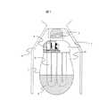
図1は本発明の電球形蛍光ランプの一実施例である。図において1はカバー部であり、このカバー部1はPBT樹脂などの電気絶縁性の耐熱性合成樹脂材料で形成され、その一端には口金2が取り付けられている。カバー部1の内部には発光管3を点灯させることを目的とした点灯回路を実装した配線基板4が収容されているとともに、この配線基板4には発光管3の外部リード線が電気的に接続されており、上記配線基板4の出力が蛍光ランプ3に印加されて、発光管3を点灯させる構成となっている。
【0010】
発光管3を覆うグローブガラス5は、グローブガラスの拡散膜塗布領域6と拡散膜を持たない無塗布領域7によって構成されている。なお、図1は照明器具への装着状態を表しており、8は照明器具のシェードを表す。口金2に商用電源を接続すると前記点灯回路を実装した配線基板4に電力が供給され配線基板4の出力が発光管3に印加され、発光管3が点灯する。
【0011】
発光管3の点灯に伴い、発光管3から発せられる光は、グローブガラス5を介して外部へ達する。ここで発光管3から発せられた光は全方向に向かって発散されるが、グローブガラスの拡散膜塗布領域6を通過した光は、拡散膜の透過率によって光束が若干低下する。一方、グローブガラス5の拡散膜無塗布領域7を通過した光は、拡散膜による光束低下の影響をほとんど受けることがない。
【0012】
一般的にグローブガラスの光透過率は90%程度であるため、従来技術の全面に拡散膜を塗布したグローブガラスをもつ電球形蛍光ランプでは、発光管自体が発する光の10%分がグローブガラスによって低下を生じる。
【0013】
これに対して、本発明の電球形蛍光ランプの場合、グローブガラス2の拡散膜塗布領域6の部分を通過する光は前記と同様に10%の光束低下を生じるが、拡散膜無塗布領域7を通過した光は拡散膜による光束低下の影響をほとんど受けない。したがって、拡散膜塗布領域6と拡散膜無塗布領域7の面積が同じと仮定した場合、両領域を通過した光の平均値が全光束となるため、発光管3自体が発する全光束の95%を透過することができるため、従来技術の全面に拡散膜を塗布したグローブガラスをもつ電球形蛍光ランプよりも5%程度の光束向上を得ることが可能となる。
【0014】
図1に示すような器具に本発明である電球形蛍光ランプを装着した場合、使用者が器具の開口部よりランプを見たときに、照明器具のシェード8により、電球形蛍光ランプは覆われるために、拡散膜の無塗布領域7を視認する事はできない。このため、全面に拡散膜を塗布したグローブガラスをもつ電球形蛍光ランプと同様の外観を得ることが可能となる。
【0015】
【発明の効果】
以上に述べたように、本発明によれば電球形蛍光ランプを器具に装着した際に、グローブガラスの拡散膜に関して、従来品と同等の外観を維持しながら、かつ拡散膜を塗布したグローブガラスによる全光束の低下率を軽減させることが可能である。
【図面の簡単な説明】
【図1】本発明の一実施例を示す電球型蛍光ランプの断面図。
【符号の説明】
1…カバー部、2…口金、3…発光管、4…配線基板、5…グローブガラス、6…拡散膜塗布領域、7…拡散膜無塗布領域、8…照明器具のシェード。[0001]
TECHNICAL FIELD OF THE INVENTION
The present invention relates to a compact fluorescent lamp.
[0002]
[Prior art]
It is well known that fluorescent lamps have higher light efficiency and a longer life than ordinary incandescent lamps. A light bulb compatible with an incandescent light bulb that can be mounted on an existing incandescent light bulb socket by attaching an E26 base commonly used for incandescent light bulbs and lighting circuit parts such as a ballast to the fluorescent lamp and mounting it as it is in an existing incandescent light bulb socket Shape fluorescent lamps have been commercialized.
[0003]
In the prior art, in order to reduce the glare of light directly entering the eyes, the above-described problem with the glare was dealt with by covering the arc tube with globe glass having a diffusion film.
[0004]
[Problems to be solved by the invention]
The bulb-type fluorescent lamp in which the globe glass coated with the diffusion film is coated on the arc tube according to the prior art has a total luminous flux due to the influence of the light transmittance of the diffusion film applied on the globe glass on the total luminous flux of the original arc tube. Is accompanied by a decrease.
[0005]
An object of the present invention is to reduce the rate of reduction of the total luminous flux due to a glove glass coated with a diffusion film while maintaining the same appearance as a conventional product with respect to the diffusion film of the globe glass when the bulb-type fluorescent lamp is mounted on the appliance. To reduce it.
[0006]
[Means for Solving the Problems]
In the present invention, the glove glass covering the light emitting tube of the bulb-type fluorescent lamp is provided with a diffusion film application region and a non-application region. That is, a diffusion film is applied from the top of the globe glass to the periphery of the maximum outer diameter formed by the globe glass to form a coating area, and from the periphery of the maximum outer diameter of the globe glass to the opening of the glove glass, the diffusion film is formed. The above problem is solved by adopting a configuration in which the diffusion film is not applied as the non-application region.
[0007]
Normally, when a bulb-type fluorescent lamp is mounted on a lighting fixture, for example, in a pendant-type lighting fixture, the lamp side is hidden by the shade of the lighting fixture, so the range in which the bulb-shaped fluorescent lamp can be viewed is the maximum from the top of the globe glass. Up to near the outer diameter. In the present invention, in order to provide a diffusion film up to around the maximum outer diameter of the globe glass, when the light bulb-shaped fluorescent lamp of the present invention is mounted on the lighting fixture, a bulb shape having a conventional globe glass with a diffusion film. The same appearance as a fluorescent lamp can be maintained.
[0008]
Furthermore, in the bulb-type fluorescent lamp of the present invention, since the glove glass has the non-coating area of the diffusion film, the light passing through the non-coating area does not cause a decrease in the luminous flux due to the diffusion film applied to the glove glass. Therefore, in comparison with the conventional technology in which the diffusion film is coated on the entire surface, the fluorescent lamp of the present invention can reduce the reduction of the total luminous flux caused by the glove glass with the diffusion film by providing the uncoated region of the diffusion film. It becomes.
[0009]
BEST MODE FOR CARRYING OUT THE INVENTION
FIG. 1 shows an embodiment of a compact fluorescent lamp according to the present invention. In FIG. 1, reference numeral 1 denotes a cover. The cover 1 is formed of an electrically insulating heat-resistant synthetic resin material such as PBT resin, and a
[0010]
The
[0011]
The light emitted from the arc tube 3 with the lighting of the arc tube 3 reaches the outside via the
[0012]
Generally, the light transmittance of globe glass is about 90%. Therefore, in the conventional bulb-type fluorescent lamp having the glove glass coated with a diffusion film on the entire surface, 10% of the light emitted from the arc tube itself is glove glass. Causes a drop.
[0013]
On the other hand, in the case of the bulb-type fluorescent lamp of the present invention, the light passing through the diffusion film coated region 6 of the
[0014]
When the bulb-type fluorescent lamp of the present invention is mounted on the apparatus as shown in FIG. 1, when the user looks at the lamp from the opening of the apparatus, the bulb-type fluorescent lamp is covered by the shade 8 of the lighting apparatus. Therefore, the non-coated
[0015]
【The invention's effect】
As described above, according to the present invention, when the bulb-type fluorescent lamp is mounted on an appliance, the glove glass with the diffusion film coated thereon while maintaining the same appearance as the conventional product with respect to the diffusion film of the glove glass. It is possible to reduce the reduction rate of the total luminous flux due to the above.
[Brief description of the drawings]
FIG. 1 is a sectional view of a bulb-type fluorescent lamp showing one embodiment of the present invention.
[Explanation of symbols]
DESCRIPTION OF SYMBOLS 1 ... Cover part, 2 ... Base, 3 ... Arc tube, 4 ... Wiring board, 5 ... Globe glass, 6 ... Diffusion film application area, 7 ... Diffusion film non-application area, 8 ... Shade of lighting equipment.
Claims (1)
Translated fromJapanesePriority Applications (1)
| Application Number | Priority Date | Filing Date | Title |
|---|---|---|---|
| JP2002351925AJP2004185997A (en) | 2002-12-04 | 2002-12-04 | Compact self-ballasted fluorescent lamp |
Applications Claiming Priority (1)
| Application Number | Priority Date | Filing Date | Title |
|---|---|---|---|
| JP2002351925AJP2004185997A (en) | 2002-12-04 | 2002-12-04 | Compact self-ballasted fluorescent lamp |
Publications (1)
| Publication Number | Publication Date |
|---|---|
| JP2004185997Atrue JP2004185997A (en) | 2004-07-02 |
Family
ID=32753679
Family Applications (1)
| Application Number | Title | Priority Date | Filing Date |
|---|---|---|---|
| JP2002351925APendingJP2004185997A (en) | 2002-12-04 | 2002-12-04 | Compact self-ballasted fluorescent lamp |
Country Status (1)
| Country | Link |
|---|---|
| JP (1) | JP2004185997A (en) |
Cited By (7)
| Publication number | Priority date | Publication date | Assignee | Title |
|---|---|---|---|---|
| WO2012001927A1 (en)* | 2010-06-28 | 2012-01-05 | 株式会社 東芝 | Led bulb |
| JP2012064367A (en)* | 2010-09-15 | 2012-03-29 | Mitsubishi Electric Corp | Light source device and self ballasted lighting system |
| JP2014241295A (en)* | 2014-08-28 | 2014-12-25 | 三菱電機株式会社 | Light source device and lighting device |
| JP2016076495A (en)* | 2010-01-12 | 2016-05-12 | ジーイー ライティング ソリューションズ エルエルシー | Transparent thermally conductive polymer composites for light source thermal management |
| US9841175B2 (en) | 2012-05-04 | 2017-12-12 | GE Lighting Solutions, LLC | Optics system for solid state lighting apparatus |
| US9951938B2 (en) | 2009-10-02 | 2018-04-24 | GE Lighting Solutions, LLC | LED lamp |
| US10340424B2 (en) | 2002-08-30 | 2019-07-02 | GE Lighting Solutions, LLC | Light emitting diode component |
- 2002
- 2002-12-04JPJP2002351925Apatent/JP2004185997A/enactivePending
Cited By (9)
| Publication number | Priority date | Publication date | Assignee | Title |
|---|---|---|---|---|
| US10340424B2 (en) | 2002-08-30 | 2019-07-02 | GE Lighting Solutions, LLC | Light emitting diode component |
| US9951938B2 (en) | 2009-10-02 | 2018-04-24 | GE Lighting Solutions, LLC | LED lamp |
| JP2016076495A (en)* | 2010-01-12 | 2016-05-12 | ジーイー ライティング ソリューションズ エルエルシー | Transparent thermally conductive polymer composites for light source thermal management |
| WO2012001927A1 (en)* | 2010-06-28 | 2012-01-05 | 株式会社 東芝 | Led bulb |
| US8955996B2 (en) | 2010-06-28 | 2015-02-17 | Kabushiki Kaisha Toshiba | LED light bulb |
| JP2012064367A (en)* | 2010-09-15 | 2012-03-29 | Mitsubishi Electric Corp | Light source device and self ballasted lighting system |
| US9841175B2 (en) | 2012-05-04 | 2017-12-12 | GE Lighting Solutions, LLC | Optics system for solid state lighting apparatus |
| US10139095B2 (en) | 2012-05-04 | 2018-11-27 | GE Lighting Solutions, LLC | Reflector and lamp comprised thereof |
| JP2014241295A (en)* | 2014-08-28 | 2014-12-25 | 三菱電機株式会社 | Light source device and lighting device |
Similar Documents
| Publication | Publication Date | Title |
|---|---|---|
| JP5406347B2 (en) | lamp | |
| JP3139714U (en) | LED lamp | |
| WO2013024557A1 (en) | Led lamp and lighting device | |
| JP5549926B2 (en) | Lamp with lamp and lighting equipment | |
| JP2010055993A (en) | Lighting system and luminaire | |
| JP5328466B2 (en) | Light bulb type lighting device | |
| WO2004016983A1 (en) | Led reflector | |
| JP2011054340A (en) | Lighting device | |
| JP2004185997A (en) | Compact self-ballasted fluorescent lamp | |
| JP2022531630A (en) | Lighting device based on solid-state lighting technology | |
| JP6603228B2 (en) | LED bulb | |
| CN204164866U (en) | Light source cell and ligthing paraphernalia | |
| JP2010153101A (en) | Bulb type lamp | |
| JP2015008149A (en) | Lamp with lamp and lighting equipment | |
| WO2012137964A1 (en) | Led illuminating lamp, and led illuminating device and led illuminating system which comprise same | |
| JP2013045544A (en) | Light-emitting device and led module | |
| JP2012129064A (en) | Lighting fixture | |
| JP2000285712A (en) | Compact fluorescent lamps and lighting equipment | |
| CN220355294U (en) | A downlight | |
| JP5066304B1 (en) | lamp | |
| JP5824680B2 (en) | Lamp and lighting device | |
| JPH10134614A (en) | Fluorescent lamp device and lighting equipment | |
| JP2013093281A (en) | Lamp with base, and lighting fixture | |
| JP5637417B2 (en) | Lamp with lamp and lighting equipment | |
| JP2010182487A (en) | Compact self-ballasted fluorescent lamp, and luminaire |
Legal Events
| Date | Code | Title | Description |
|---|---|---|---|
| RD07 | Notification of extinguishment of power of attorney | Free format text:JAPANESE INTERMEDIATE CODE: A7427 Effective date:20050721 | |
| A621 | Written request for application examination | Free format text:JAPANESE INTERMEDIATE CODE: A621 Effective date:20050921 | |
| A977 | Report on retrieval | Free format text:JAPANESE INTERMEDIATE CODE: A971007 Effective date:20080402 | |
| A131 | Notification of reasons for refusal | Free format text:JAPANESE INTERMEDIATE CODE: A131 Effective date:20080610 | |
| A02 | Decision of refusal | Free format text:JAPANESE INTERMEDIATE CODE: A02 Effective date:20081014 |