JP2004174265A - Method and apparatus for achieving correct limb alignment in unicondylar knee arthroplasty - Google Patents
Method and apparatus for achieving correct limb alignment in unicondylar knee arthroplastyDownload PDFInfo
- Publication number
- JP2004174265A JP2004174265AJP2003397459AJP2003397459AJP2004174265AJP 2004174265 AJP2004174265 AJP 2004174265AJP 2003397459 AJP2003397459 AJP 2003397459AJP 2003397459 AJP2003397459 AJP 2003397459AJP 2004174265 AJP2004174265 AJP 2004174265A
- Authority
- JP
- Japan
- Prior art keywords
- femoral
- tibial
- alignment
- alignment rod
- spacer
- Prior art date
- Legal status (The legal status is an assumption and is not a legal conclusion. Google has not performed a legal analysis and makes no representation as to the accuracy of the status listed.)
- Granted
Links
- 210000003127kneeAnatomy0.000titleclaimsabstractdescription77
- 238000000034methodMethods0.000titleclaimsabstractdescription33
- 210000003414extremityAnatomy0.000titleclaimsabstractdescription22
- 238000011882arthroplastyMethods0.000titleabstractdescription21
- 210000002303tibiaAnatomy0.000claimsabstractdescription60
- 125000006850spacer groupChemical group0.000claimsdescription62
- 210000000689upper legAnatomy0.000claimsdescription62
- 210000000629knee jointAnatomy0.000claimsdescription27
- 210000000988bone and boneAnatomy0.000claimsdescription19
- 238000003780insertionMethods0.000claimsdescription4
- 230000037431insertionEffects0.000claimsdescription4
- 210000003423ankleAnatomy0.000description30
- 238000002271resectionMethods0.000description23
- 210000003128headAnatomy0.000description14
- 210000002414legAnatomy0.000description11
- 230000015572biosynthetic processEffects0.000description9
- 239000007943implantSubstances0.000description8
- 241000469816VarusSpecies0.000description7
- 230000014759maintenance of locationEffects0.000description6
- 210000004417patellaAnatomy0.000description6
- 210000004872soft tissueAnatomy0.000description5
- 210000000845cartilageAnatomy0.000description4
- 210000004439collateral ligamentAnatomy0.000description4
- 238000001356surgical procedureMethods0.000description4
- 241001227561ValgusSpecies0.000description3
- 238000002679ablationMethods0.000description3
- 210000000544articulatio talocruralisAnatomy0.000description3
- 238000010420art techniqueMethods0.000description2
- 210000000281joint capsuleAnatomy0.000description2
- 210000003041ligamentAnatomy0.000description2
- 210000003205muscleAnatomy0.000description2
- 238000007493shaping processMethods0.000description2
- 210000001519tissueAnatomy0.000description2
- 208000008558OsteophyteDiseases0.000description1
- 230000002159abnormal effectEffects0.000description1
- 230000006978adaptationEffects0.000description1
- 210000000577adipose tissueAnatomy0.000description1
- 238000002266amputationMethods0.000description1
- 239000002775capsuleSubstances0.000description1
- 239000011248coating agentSubstances0.000description1
- 238000000576coating methodMethods0.000description1
- 230000003247decreasing effectEffects0.000description1
- 238000010586diagramMethods0.000description1
- 201000010099diseaseDiseases0.000description1
- 208000037265diseases, disorders, signs and symptomsDiseases0.000description1
- 238000005553drillingMethods0.000description1
- 230000000694effectsEffects0.000description1
- 230000003628erosive effectEffects0.000description1
- 201000010934exostosisDiseases0.000description1
- 210000000744eyelidAnatomy0.000description1
- 239000012634fragmentSubstances0.000description1
- 230000002439hemostatic effectEffects0.000description1
- 210000003141lower extremityAnatomy0.000description1
- 239000003550markerSubstances0.000description1
- 238000002324minimally invasive surgeryMethods0.000description1
- 230000007935neutral effectEffects0.000description1
- 230000000399orthopedic effectEffects0.000description1
- 201000008482osteoarthritisDiseases0.000description1
- 230000002093peripheral effectEffects0.000description1
- 230000001737promoting effectEffects0.000description1
- 238000011084recoveryMethods0.000description1
- 210000001203second metatarsal boneAnatomy0.000description1
- 230000036558skin tensionEffects0.000description1
- 210000003699striated muscleAnatomy0.000description1
- 230000002792vascularEffects0.000description1
- 238000012800visualizationMethods0.000description1
Images


Classifications
- A—HUMAN NECESSITIES
- A61—MEDICAL OR VETERINARY SCIENCE; HYGIENE
- A61B—DIAGNOSIS; SURGERY; IDENTIFICATION
- A61B17/00—Surgical instruments, devices or methods
- A61B17/14—Surgical saws
- A61B17/15—Guides therefor
- A61B17/154—Guides therefor for preparing bone for knee prosthesis
- A—HUMAN NECESSITIES
- A61—MEDICAL OR VETERINARY SCIENCE; HYGIENE
- A61B—DIAGNOSIS; SURGERY; IDENTIFICATION
- A61B17/00—Surgical instruments, devices or methods
- A61B17/14—Surgical saws
- A61B17/15—Guides therefor
- A61B17/154—Guides therefor for preparing bone for knee prosthesis
- A61B17/155—Cutting femur
- A—HUMAN NECESSITIES
- A61—MEDICAL OR VETERINARY SCIENCE; HYGIENE
- A61B—DIAGNOSIS; SURGERY; IDENTIFICATION
- A61B17/00—Surgical instruments, devices or methods
- A61B17/14—Surgical saws
- A61B17/15—Guides therefor
- A61B17/154—Guides therefor for preparing bone for knee prosthesis
- A61B17/157—Cutting tibia
Landscapes
- Health & Medical Sciences (AREA)
- Surgery (AREA)
- Life Sciences & Earth Sciences (AREA)
- Biomedical Technology (AREA)
- Medical Informatics (AREA)
- Oral & Maxillofacial Surgery (AREA)
- Nuclear Medicine, Radiotherapy & Molecular Imaging (AREA)
- Transplantation (AREA)
- Physical Education & Sports Medicine (AREA)
- Engineering & Computer Science (AREA)
- Orthopedic Medicine & Surgery (AREA)
- Heart & Thoracic Surgery (AREA)
- Dentistry (AREA)
- Molecular Biology (AREA)
- Animal Behavior & Ethology (AREA)
- General Health & Medical Sciences (AREA)
- Public Health (AREA)
- Veterinary Medicine (AREA)
- Surgical Instruments (AREA)
- Prostheses (AREA)
Abstract
Description
Translated fromJapanese本発明は、単関節丘膝関節形成、より詳しくは、最低限に侵襲的な単関節丘膝関節形成を含む、正しい肢アライメントを達成して、単関節丘膝関節形成中に遠位大腿骨切断部を近位脛骨切断部に連結するための方法及び装置に関する。 The present invention achieves correct limb alignment, including monoarticular knee arthroplasty, and more particularly minimally invasive monoarticular knee arthroplasty, so that the distal femur during monoarticular knee arthroplasty is achieved. The present invention relates to a method and apparatus for connecting a cut to a proximal tibial cut.
患者の関節のすべて又は一部分を置き換えるための整形外科処置が、過去30年にわたって開発されてきた。現在、骨を調製して移植体を設置するために使用される処置は、一般に開口処置と呼ばれる。この説明のために、「開口処置」という用語は、処置を指す。この場合、切り口は、特定の関節表面の大部分を完全に露出するために皮膚と下層の組織とを通して形成される。全体及び単関節丘膝関節形成の両方において、開口処置のための典型的な切り口の長さは約20cm(約8インチ)〜約25cm(約10インチ)である。皮膚内の初期切開の後、用意すべき領域を完全に露出するために、内部の傷口が拡大されることがある。この方法は、骨表面の優れた観察を外科医に提供するが、筋肉を含む軟質組織に対する下層の損傷は、外科手術後に患者のリハビリテーション時間を長くする可能性がある。移植体は外科手術時に固定し得るが、外科手術中に傷ついた組織が完全に治るまで、数週又はおそらくは数カ月かかるかもしれない。 Orthopedic procedures to replace all or part of a patient's joint have been developed over the past 30 years. Currently, the procedure used to prepare bone and place the implant is commonly referred to as an open procedure. For the purposes of this description, the term “opening procedure” refers to a procedure. In this case, an incision is made through the skin and underlying tissue to fully expose most of the particular articular surface. A typical incision length for an open procedure is about 20 cm (about 8 inches) to about 25 cm (about 10 inches), both for total and single joint knee arthroplasty. After an initial incision in the skin, the internal wound may be enlarged to fully expose the area to be prepared. Although this method provides the surgeon with an excellent view of the bone surface, underlying damage to soft tissue, including muscles, can increase patient rehabilitation time after surgery. The implant can be fixed at the time of surgery, but it may take weeks or perhaps months to fully heal the damaged tissue during the surgery.
単一区画膝関節形成は、典型的に、例えば、膝の内側(内反変形)又は横方向(外反変形)区画に影響を及ぼす変形性関節症によって引き起こされる内反又は外反変形を矯正するために利用される。伝統的に、単関節丘膝関節形成は開口処置であり、外科医が、膝を露出した後に膝の適切な区画から、遠位大腿骨及び近位脛骨の部分を含む疾患のある骨さもなければ望ましくない骨を切除する開口処置である。冒された区画の遠位大腿骨及び近位脛骨はまた、単関節丘膝補てつ装具を受容ように賦形される。 Single compartment knee arthroplasty typically corrects varus or valgus deformity caused by osteoarthritis affecting, for example, the medial (varus deformity) or lateral (valgus deformity) compartment of the knee To be used. Traditionally, monoclinic knee arthroplasty is an open procedure, in which the surgeon removes the diseased bone, including the distal femur and proximal tibia parts, from the appropriate section of the knee after exposing the knee. Opening procedure to remove unwanted bone. The distal femur and proximal tibia of the affected section are also shaped to receive a monoarticular knee prosthesis.
従来の単関節丘膝関節形成では、脚アライメントには、試行錯誤の技術が必要であり、この場合、外科医は、限定された数の厚さで脛骨補てつ装具が利用可能であるという経験と知識に基づき、遠位大腿骨切断部及び近位脛骨切断部の一方を作り、その後に遠位大腿骨切断部及び近位脛骨切断部の他方の位置を選択する。典型的に、近位脛骨切断部は、疾患のある骨さもなければ望ましくない骨の十分な除去を保証しつつ、近位脛骨の最少の量を除去するように作られる。残りの大腿骨切断部は、大腿補てつ装具を受容するように大腿骨の賦形を完成するために作られる。大腿骨及び脛骨切断部が完成した後、大腿骨補てつ装具及び脛骨補てつ装具、あるいはそれらの暫定的なバージョがンが一時的に移植され、脚アライメントは外科医によって再検討される。脛骨補てつ装具が一体の軸受構成要素を含まない場合、別個の軸受構成要素も移植される。脚アライメントを調整するために、外科医は、脛骨補てつ装具、又は軸受構成要素を、厚さを増した又は減らした代わりの脛骨補てつ装具、又は軸受構成要素で置き換えることができる。外科医はまた、適切な脚アライメントを達成するために、大腿骨を再切断し及び/又は異なる大腿骨移植体を使用することが可能である。外科医はまた、より多くの脛骨ストックを除去し、再び、以前に使用した脛骨補てつ装具を使用するか、あるいは以前に使用した脛骨補てつ装具を、異なる厚さの脛骨補てつ装具で置き換えることができる。適切な脚アライメント及び軟質組織の緊張が達成されたと、外科医が信じるまで、試行錯誤の上記の処置が行われる。 In traditional single-knee knee arthroplasty, leg alignment requires trial and error techniques, in which the surgeon has the experience that a limited number of thicknesses are available for a tibial prosthesis. Based on the knowledge, one of the distal femur cutting portion and the proximal tibial cutting portion is made, and then the other position of the distal femoral cutting portion and the proximal tibial cutting portion is selected. Typically, the proximal tibial amputation is made to remove a minimal amount of the proximal tibia while ensuring sufficient removal of diseased or otherwise undesired bone. The remaining femoral cutting is made to complete the femoral shaping to receive the femoral prosthesis. After the femur and tibia cuts are completed, the femoral prosthesis and / or tibial prosthesis, or a temporary version thereof, is temporarily implanted and the leg alignment is reviewed by the surgeon. If the tibial prosthesis does not include an integral bearing component, a separate bearing component is also implanted. To adjust the leg alignment, the surgeon can replace the tibial prosthetic device or bearing component with an alternative tibial prosthetic device or bearing component of increased or decreased thickness. The surgeon can also recut the femur and / or use a different femoral implant to achieve proper leg alignment. The surgeon can also remove more tibial stock and again use the previously used tibial prosthesis, or replace the previously used tibial prosthesis with a different thickness tibial prosthesis. Can be replaced. The above trial and error procedure is performed until the surgeon believes that proper leg alignment and soft tissue tension has been achieved.
単一区画の膝関節形成を実行する際に利用される従来の試行錯誤の技術は、退屈であり、時間を浪費し、脛骨及び/又は大腿骨の過度の除去をもたらす可能性がある。1つの代わりの従来技術の技術は、単関節丘膝補てつ装具を受容する膝の区画内の間隔にわたって延在する離間機構を利用する。この従来技術の技術では、外科医が肢アライメントに満足するまで、区画離間が延長される。膝区画を延長するために使用される装置は、切断ブロック用の基準として使用され、このブロックを通して、膝を完全に伸展して遠位大腿骨及び近位脛骨が切断される。この技術は不都合であるが、その理由は、多くの外科医は、膝が完全に伸展しているときに骨に近い膝の背後の膝窩構造を損傷することを恐れるため、膝が完全に伸展しているときに脛骨を切断することを望まないからである。膝が屈曲されるとき、膝窩構造は骨から引き離され、膝窩構造を損傷することなく近位脛骨を切断する際に追加の誤りの余地をもたらす。 Traditional trial and error techniques utilized in performing single-compartment knee arthroplasty can be tedious, time consuming, and result in excessive removal of the tibia and / or femur. One alternative prior art technique utilizes a spacing mechanism that extends over a distance in the knee compartment that receives the monoclinic knee prosthesis. In this prior art technique, compartment spacing is extended until the surgeon is satisfied with limb alignment. The device used to extend the knee compartment is used as a reference for the cutting block, through which the knee is fully extended and the distal femur and proximal tibia are cut. This technique is inconvenient because many surgeons fear that they will damage the popliteal structure behind the knee near the bone when the knee is fully extended, so the knee is fully extended This is because it is not desired to cut the tibia when it is in progress. When the knee is flexed, the popliteal structure is pulled away from the bone, providing additional error in cutting the proximal tibia without damaging the popliteal structure.
関連技術において、単関節丘膝関節形成に正しい肢アライメントを行うための最低限に侵襲的な方法及び装置が必要とされている。 There is a need in the related art for a minimally invasive method and apparatus for correct limb alignment for single joint knee arthroplasty.
関連技術において、所定の間隔を有する遠位大腿骨切断部及び近位脛骨切断部を作ることができ、屈曲部の近位脛骨の切除を可能にする切断ガイド装置がさらに必要とされている。 There is a further need in the related art for a cutting guide device that can make distal femur and proximal tibial cuts with a predetermined spacing and allows for resection of the proximal tibia of the bend.
本発明は、単関節丘膝関節形成中に正しい肢アライメントを行うために最低限に侵襲的な処置を提供する。膝のどの区画が補てつ装具を受容しているかに応じて、膝関節を露出するために中間又は横方向の切り口が作られる。本発明の方法で使用される切り口は、従来の開口処置の切り口よりも小さい。傷口を展開した後、膝の関連する区画の前方脛骨ボスが切除され、また本発明による調整可能なアライメントブロックが膝の関連する区画内に挿入される。 The present invention provides a minimally invasive procedure for correct limb alignment during monoarticular knee arthroplasty. Depending on which section of the knee is receiving the prosthetic brace, an intermediate or lateral cut is made to expose the knee joint. The incision used in the method of the present invention is smaller than the incision of the conventional opening procedure. After deploying the wound, the anterior tibial boss of the relevant section of the knee is excised and an adjustable alignment block according to the present invention is inserted into the relevant section of the knee.
本発明の調整可能なアライメントブロックは、大腿骨に接触するための大腿骨パドルと、脛骨に接触するための脛骨パドルを含む。使用時、大腿骨及び脛骨パドルは、前方脛骨ボスを除去した後に膝の関連する区画内に挿入される。本発明の装置は、調整可能なアライメントブロックに取付け可能であると共に端部を収容するアライメントロッドを有するアライメントタワーを含み、アライメントタワーは、膝の区画内に挿入された調整可能なアライメントブロックに取り付けられるとき、膝の関節丘の間に配置される。位置決めタワーの端部を収容する位置決めロッドは、1対の穴、一方は大腿骨アライメントロッドを受容するための穴、他方は脛骨アライメントロッドを受容するための穴を含む。端部を受容するアライメントロッドの適切な穴に挿入された場合、大腿骨及び脛骨アライメントロッドは、膝の関節丘の間に配置された端部を有し、2本のロッドは平行である。膝をアライメントするために、大腿骨アライメントロッドは大腿骨の機械軸とアライメントされ、下肢は、脛骨アライメントロッドが脛骨機械軸とアライメントするまで移動される。関節アライメントの矯正により、調整可能なアライメントブロックの脛骨パドルは、大腿骨パドルが大腿骨に接触するまで大腿骨パドルから移動され、同時に脛骨パドルは脛骨に接触して、適切なアライメントに膝を維持し、すなわち、肢アライメントの適切なバランス及び軟質組織のバランスを維持する。調整可能なアライメントブロックは脛骨と大腿骨とに固定され、次に、アライメントタワー及びアライメントロッドが取り除かれる。 The adjustable alignment block of the present invention includes a femoral paddle for contacting the femur and a tibial paddle for contacting the tibia. In use, the femur and tibial paddle are inserted into the relevant compartment of the knee after removing the anterior tibial boss. The apparatus of the present invention includes an alignment tower that is attachable to an adjustable alignment block and has an alignment rod that houses an end, the alignment tower being attached to an adjustable alignment block inserted into a knee compartment. When placed, it is placed between the knee condyles. The positioning rod that houses the end of the positioning tower includes a pair of holes, one for receiving the femoral alignment rod and the other for receiving the tibial alignment rod. When inserted into the appropriate hole in the alignment rod that receives the ends, the femur and tibial alignment rods have ends positioned between the knee condyles and the two rods are parallel. To align the knee, the femoral alignment rod is aligned with the femoral mechanical axis and the lower limb is moved until the tibial alignment rod aligns with the tibial mechanical axis. With joint alignment correction, the adjustable alignment block tibial paddle is moved away from the femoral paddle until the femoral paddle contacts the femur, while the tibial paddle contacts the tibia and maintains the knee in proper alignment That is, maintaining an appropriate balance of limb alignment and soft tissue balance. The adjustable alignment block is secured to the tibia and femur, and then the alignment tower and alignment rod are removed.
本発明の調整可能なアライメントブロックは、遠位大腿骨切断部が作られる大腿骨切断スロットを含む。大腿骨切断スロットは、大腿骨パドルから所定の距離だけ離間され、適切な量の大腿骨ストックの除去を可能にする。膝を屈曲し、また大腿骨切断ブロックを脛骨と大腿骨とに固定し、振動鋸又は他の適切な道具を利用して、遠位大腿骨を切除する。遠位大腿骨を切除した後、調整可能なアライメントブロックが取り除かれ、調整可能なアライメントブロックを脛骨に固定するために使用された1対の頭なし固定装置を残す。頭なし固定装置は大腿骨切断スロットから所定の距離だけ離間され、遠位大腿骨切断部を近位脛骨切断部に連結するための基準として使用される。 The adjustable alignment block of the present invention includes a femoral cutting slot in which a distal femoral cutting is made. The femoral cutting slot is spaced a predetermined distance from the femoral paddle to allow removal of an appropriate amount of femoral stock. The knee is bent and the femoral cutting block is secured to the tibia and femur and the distal femur is resected using a vibrating saw or other suitable tool. After excising the distal femur, the adjustable alignment block is removed, leaving a pair of headless fixation devices used to secure the adjustable alignment block to the tibia. The headless fixation device is spaced a predetermined distance from the femoral cutting slot and is used as a reference for connecting the distal femoral cut to the proximal tibial cut.
今や、近位脛骨を切除するために、本発明の脛骨切断ブロックが使用される。本発明の脛骨切断ブロックは、ブロック内の頭なし固定装置の挿入を受け入れるように寸法決めかつ離間されたいくつかの孔対を含む。脛骨切断ブロックの孔対の各々は、異なる移植体の厚さに対応する。脛骨切断ブロックはまた、近位脛骨切断部を作ることができる脛骨切断スロットを含む。脛骨切断部は、所望の移植体用の適切な孔対内に頭なし固定装置を配置することによって脛骨に取り付けられ、近位脛骨内でサジタル切断部を作った後、水平な脛骨切断部が脛骨切断スロットを通して作られる。 Now, the tibial cutting block of the present invention is used to resect the proximal tibia. The tibial cutting block of the present invention includes a number of hole pairs dimensioned and spaced to accept insertion of a headless fixation device within the block. Each hole pair of the tibial cutting block corresponds to a different implant thickness. The tibial cutting block also includes a tibial cutting slot that can create a proximal tibial cut. The tibial cut is attached to the tibia by placing a headless fixation device in the appropriate hole pair for the desired implant, and after making a sagittal cut in the proximal tibia, the horizontal tibial cut is Made through a cutting slot.
本発明の利点は、本明細書に開示した技術の最低限に侵襲的な性質の故に患者の回復を促進しつつ、単関節丘膝関節形成を実行する能力である。 An advantage of the present invention is the ability to perform monoarticular knee arthroplasty while facilitating patient recovery because of the minimally invasive nature of the techniques disclosed herein.
本発明の別の技術的な利点は、所定のアライメントと軟質組織とのバランスの確立であり、遠位大腿骨及び近位脛骨の上に連結された並列の骨切断部による正確な部品位置決めを保証する。 Another technical advantage of the present invention is the establishment of a balance between predetermined alignment and soft tissue, and accurate part positioning by parallel bone cuts connected on the distal femur and proximal tibia. Guarantee.
本発明の他の利点は、屈曲部の近位脛骨の切除を可能にしつつ、遠位大腿骨及び近位脛骨の上の骨切断部を連結する能力である。 Another advantage of the present invention is the ability to connect a bone cut on the distal femur and the proximal tibia while allowing resection of the proximal tibia of the bend.
添付図に関連して行われる本発明の実施態様の次の説明を参照して、本発明の前述及び他の特徴と利点、及びそれらを達成する方法がより明白になり、また本発明それ自体がより良く理解されるであろう。 The foregoing and other features and advantages of the invention and the manner in which they are accomplished will become more apparent and the invention itself will become apparent upon reference to the following description of embodiments of the invention taken in conjunction with the accompanying drawings. Will be better understood.
複数の図面全体にわたって、対応する参照番号は対応する部分を示す。本明細書に説明する実施例は、1つの形態の本発明の好ましい一実施態様を示し、またこのような実施例は本発明の範囲を限定すると解釈すべきではない。 Corresponding reference characters indicate corresponding parts throughout the several views. The examples described herein illustrate one preferred form of the invention in one form and such examples should not be construed as limiting the scope of the invention.
以下の説明は、中間区画の単関節丘膝関節形成に関する。中間区画の単関節丘膝関節形成に関して記述し、本発明の原理は横方向の区画に適用することができるが、膝の横方向の区画を置き換える場合、僅かに長い切り口が必要となることがある。 The following description relates to the formation of a single-joint condylar knee joint in the middle section. Described with respect to the single-compartment knee joint formation in the middle section, the principles of the present invention can be applied to the lateral section, but a slightly longer cut may be required when replacing the lateral section of the knee. is there.
手術前の計画
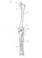
本発明による単関節丘膝関節形成を実行する前に、冒された膝の重さを支える前方/後方及び横方向のX線写真を取らなければならない。さらに、好ましくは足関節を含む大腿骨頭部、膝、また可能な限り脛骨の中心を示す仰臥位の前方/後方のX線写真を取らなければならない。この最後のX線では、外科医は、膝の大腿骨頭部の中心から遠位大腿骨の中心に線を引き、また脛骨骨幹の中心の下方に第2の線を引くことができる。これらの2つの線によって形成された角度は、図2に示したように変形∀の角度を示す。Pre-surgical planning Before performing a single-joint knee joint formation according to the present invention, anterior / posterior and lateral radiographs that support the weight of the affected knee must be taken. In addition, anterior / posterior radiographs of the supine position, preferably showing the center of the femoral head, knee, and tibia as much as possible, should be taken. With this last X-ray, the surgeon can draw a line from the center of the femoral head of the knee to the center of the distal femur and a second line below the center of the tibial shaft. The angle formed by these two lines indicates the angle of the deformed eyelid as shown in FIG.
図2は、内反変形を有する膝関節24を概略的に示している。図2に示したように、膝24の大腿骨頭部16の中心から遠位大腿骨18の中心に引かれた線20’は、脛骨12’の骨幹の中心の下方に引かれた線22’と角度∀を形成する。この角度∀は膝関節24の内反変形の角度を示している。図1は健康な膝関節14を示している。図1に示したように、膝14の大腿骨頭部16の中心から遠位大腿骨20の中心に引かれた線20は、脛骨12の骨幹の中心の下方に引かれた線22と同一直線上にあり、変形なしの膝関節を示している。変形∀の角度が15度以上ならば、患者は、単一区画の膝関節形成の候補ではないであろう。 FIG. 2 schematically shows a knee joint 24 having a varus deformity. As shown in FIG. 2, a
仰臥位の患者では、足関節領域は弾性包装体で巻き付けられ、近位大腿骨のアクセス可能性が点検される。近位大腿骨は、図2に示しまた上述したように、変形∀の角度を決定するために使用される大腿骨頭部位置の決定を可能にするためにアクセス可能でなければならない。この時点において、大腿骨頭部の位置を識別するために解剖学的なランドマークを利用することが可能である。1つの模範的な実施態様では、EKG電極のようなマーカを大腿骨頭部の中心の上方に配置して、基準点として利用し得る。1つの模範的な実施態様では、大腿骨頭部の位置は前方/後方のX線写真により確認される。 In a supine patient, the ankle region is wrapped with an elastic wrap to check the accessibility of the proximal femur. The proximal femur must be accessible to allow determination of the position of the femoral head used to determine the angle of the deformity heel as shown in FIG. 2 and described above. At this point, anatomical landmarks can be used to identify the location of the femoral head. In one exemplary embodiment, a marker such as an EKG electrode can be placed above the center of the femoral head and used as a reference point. In one exemplary embodiment, the position of the femoral head is confirmed by an anterior / posterior radiograph.
外科的処置
図3を参照すると、膝関節を露出するために患者脚部26内に切り口28が作られる。外科医の選択に応じて、屈曲部又は伸展部に切り口28を作ることができる。切り口28は、開示した模範的な実施態様では、図3に示したように、膝蓋の上極から6〜10cm、関節線の約2cm下に脛骨結節に隣接して延在する中間副膝蓋の切り口である。横方向区画の単関節丘膝関節形成が実行されている場合、切り口は、膝蓋の上極から関節線の約2cm下に脛骨結節に隣接して延在する横方向の異常膝蓋切り口である。図3と図4は右の膝を示し、他方、本文献の残りの図面は左の膝を示している。本発明の処置は、当然、左右両方の膝に適用できる。Surgical Procedure Referring to FIG. 3, a
切り口28を作った後、傷口は関節包を露出するために展開される。図4を参照すると、被膜切り口30は、図4に示したような大腿骨関節丘の前方縁を露出する点に、切り口28と一致して広筋斜紋筋の遠位の関節包内に作られる。膝関節の視覚化を促進するために、脂肪パッドを摘出することが可能である。今や、軟質組織は、脛骨から関節線に沿って側副靱帯に向かって、骨膜下に反転されるが、側副靱帯内には反転されない。露出した膝区画内で、前方関節間軟骨の部分が除去される。1つの模範的な実施態様では、前方関節間軟骨の約3分の1が除去される。関節間軟骨の残部は、遠位大腿骨及び近位脛骨の切除後に除去される。 After making the
次に、関節は創面切除され、また脛骨棘状突起又は十字形靭帯との作用を避けるために、関節丘間オステオファイトが除去される。さらに、側副靱帯及び被膜に干渉する周縁オステオファイトが除去される。例えば、中間区画疾患では、オステオファイトは脛骨隆起の横方向の面に確認される。 The joint is then debated and the interlobe osteophyte is removed to avoid effects with the tibial spinous process or cruciate ligament. In addition, peripheral osteophite that interferes with the collateral ligament and the coating is removed. For example, in mid-compartment disease, osteofite is identified on the lateral surface of the tibial protuberance.
図5を参照すると、膝を屈曲して、振動鋸32が露出した膝区画内に挿入されかつ脛骨12’に適用され、振動鋸ブレード36は前方脛骨ボス34を切除するように作動する。次に、膝が完全に伸展され、タオルを足関節の下に配置して膝を完全に伸展維持するのを補助する。この位置において、脚アライメントは受動的に矯正され、すなわち視覚的に正しいように見られるまで矯正される。 Referring to FIG. 5, with the knee flexed, the oscillating saw 32 is inserted into the exposed knee section and applied to the
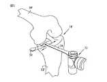
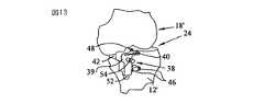
図13を参照すると、次に、調整可能なアライメントブロック38(さらに図6〜図12に図示)が、中間大腿骨関節丘と、前方脛骨ボス34が取り除かれる脛骨の部分との間に配置された大腿骨パドル42(図7)と共に配置される。調整可能なアライメントブロック38を挿入する前に、脛骨パドル44は、図7と図9に示したように閉位置に配置される。 Referring to FIG. 13, an adjustable alignment block 38 (further illustrated in FIGS. 6-12) is then placed between the intermediate femoral condyle and the portion of the tibia where the
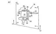
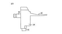
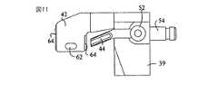
図8〜図12を参照すると、調整可能なアライメントブロック38は、そこから延在する大腿骨パドル42を有する本体39を含む。図11に示したように、大腿骨パドル42は、反対側のスペーサ斜面64とスペーサスロット62とを含む。スペーサ斜面64とスペーサスロット62は、以下にさらに記述するように、マイナス2mmの大腿骨スペーサ56に関連して利用される。大腿骨パドル42の反対側に、アライメントタワーボス54が、調整可能なアライメントブロック38の本体39から延在する。本体39は、以下にさらに記述するように、調整可能なアライメントブロック38を大腿骨と脛骨とに貼り付けるために本体内に形成された穴46、48を含む。調整可能なアライメントブロック38の本体39は、以下にさらに記述するように、遠位大腿骨切断部が作られる大腿骨切断スロット40をさらに含む。 With reference to FIGS. 8-12, the
調整可能なアライメントブロック38は、脛骨パドル44が配置される脛骨パドル溝50をさらに含む。脛骨パドル溝50は、図7と図9に示した調整可能なアライメントブロック38の閉位置の間の脛骨パドル44の運動を、図6と図10に示したアライメントブロックの開位置に案内する。図8に示したように、ねじ付きシャフト60は、調整可能なアライメントブロック38の本体39の細長い穴に回転可能に配置される。脛骨パドル作動ノブ52がねじ付きシャフト60に固定され、また調整可能なアライメントブロック38の本体39から延在して、ねじ付きシャフト60の作動を可能にする。脛骨パドル44は、ねじ付きシャフト60の回転を引き起こす脛骨パドル作動ノブ52の回転が開位置と閉位置との間の脛骨パドル44を作動するようにねじ付きシャフト60の隣接するねじ山の間に配置された端部を含む。 The
本図に示した調整可能なアライメントブロック38は、左中間/右横方向の調整可能なアライメントブロックである。右中間の単関節丘膝関節形成及び左横方向の単関節丘膝関節形成のために、代わりのアライメントブロックを利用することができる。このような代わりのアライメントブロックは、本図に示したアライメントブロック38の鏡像である。図12を参照すると、鏡像のアライメントブロックは、脛骨パドル作動ノブ52の左に配置された脛骨固着穴46を含むであろう。さらに、代わりの実施態様の調整可能なアライメントブロックでは、大腿骨切断スロット40は、図12の図面から脛骨パドル作動ノブ52の左にさらに延在する。 The
関節が余りにもきつく、調整可能なアライメントブロック38の大腿骨パドル42を、上述のような膝24内に挿入できない場合、図5を参照して記述したように、アライメントブロック38を挿入するために、追加の前方脛骨ボスを取り除いてより大きなスペースを形成しなければならない。露出改良のため、膝蓋オステオファイトを取り除くことができる。有利に、本発明の技術は膝蓋の移動を必要としない。関節を適切にアライメントして保持するために、調整可能なアライメントブロック38が使用され、さらに以下に詳細に記述するように、遠位大腿骨切断部を作るときに切除ガイドとして使用される。 If the
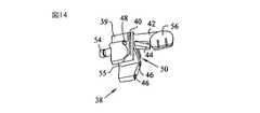
大腿骨関節丘の相当の腐食がある場合、2mm小さい骨を遠位大腿骨関節丘から切除することが可能である。このような場合、図14に示したような調整可能なアライメントブロック38の大腿骨パドル42の頂部に、マイナス2mmの遠位大腿骨スペーサ56(図28〜図31)が配置される。調整可能なアライメントブロック38の大腿骨パドル42にマイナス2mm遠位大腿骨スペーサ56を取り付けて、図13に示した位置から、すなわち、調整可能なアライメントブロック38の大腿骨パドル42にマイナス2mmの遠位大腿骨スペーサ56が固定されない位置から、大腿骨切断スロット40が遠位大腿骨18’に対して遠位に2mm移動される。したがって、マイナス2mmの遠位大腿骨スペーサを利用するときに大腿骨切断スロット40を通して振動鋸を配置するとき、2mm小さい大腿骨が切除される。 If there is considerable erosion of the femoral condyle, a 2 mm smaller bone can be excised from the distal femoral condyle. In such a case, a minus 2 mm distal femoral spacer 56 (FIGS. 28-31) is placed on top of the
マイナス2mmの大腿骨スペーサ56が図28〜図31に詳細に示されている。図28に示したように、マイナス2mmの大腿骨スペーサ56は、2mmの高さHを有する。これを念頭において、図14に示したような大腿骨パドル42の頂部にマイナス2mm大腿骨スペーサ56を配置して、切断スロット40は、調整可能なアライメントブロック38がマイナス2mmの大腿骨スペーサ56なしに膝関節24に配置されるとき、大腿骨18’に沿って大腿骨の位置に対して遠位に2mm移動される。 A minus 2 mm
遠位大腿骨切除の深さを調整するために、高さが変わる大腿骨スペーサを本発明に従って利用し得る。マイナス2mmの大腿骨スペーサ56は、図28〜図31に詳細に示されている。図31に示したように、大腿骨スペーサ56は、調整可能なアライメントブロック38の大腿骨パドル42に対し遠位大腿骨スペーサ56の確保を行うために、大腿骨スペーサの下面から延在するあり継ぎ84を含む。図11に示したように、調整可能なアライメントブロック38の大腿骨パドル42は反対側のスペーサ斜面64を含み、この斜面は、マイナス2mmの大腿骨スペーサ56のあり継ぎ84の拡張を促進して、大腿骨パドル42の頂部のマイナス2mmの大腿骨スペーサ56の位置決めを可能にする。さらに、図29と図30を参照すると、マイナス2mmの大腿骨スペーサ56は、マイナス2mmの大腿骨スペーサ56を、調整可能なアライメントブロック38の大腿骨パドル42に固定するときにあり継ぎ84の外側方向の拡張を促進する1対の拡張スロット58を含む。マイナス2mmの大腿骨スペーサ56が大腿骨パドル42に固定されるとき、その調整可能なアライメントブロック突出部66は、大腿骨パドル42に対するマイナス2mmの大腿骨スペーサ56の摺動を防止するために、大腿骨パドル42のスペーサスロット62内に嵌合する。マイナス2mmの大腿骨スペーサ56を大腿骨パドル42から取り外すために、プライバーがそれらの間に挿入され、調整可能なアライメントブロック突出部66を大腿骨パドル42のスペーサスロット62から付勢する。次に、マイナス2mmの大腿骨スペーサ56を摺動して、大腿骨パドル42との係合を解除することができる。 To adjust the depth of the distal femoral resection, a femoral spacer with varying height may be utilized in accordance with the present invention. The minus 2 mm
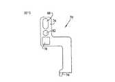
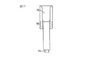
大腿骨パドル42と位置決めされた調整可能なアライメントブロック38を、図13に示したような冒された区画内に形成された空間に配置して(アライメントブロックに固定されるマイナス2mmの遠位大腿骨スペーサ56付き又はそれなしに)、図15〜図18に詳細に示したアライメントタワー70は、図19に示したように、調整可能なアライメントブロック38に固定される。図18を参照すると、アライメントタワー70は、調整可能なアライメントブロック38にアライメントタワー70が固定されるときにアライメントタワーボス54を当該穴内に配置するように寸法決めされたボス穴72を含む。アライメントタワー70は、調整可能なアライメントブロック38にアライメントタワー70が固定されるときに、調整可能なアライメントブロック38の基部55に当接するアライメント突出部74をさらに含む。アライメント突出部74は、図15と図18に示したように賦形されるウェッジである。調整可能なアライメントブロック38のアライメントタワーボス54がアライメントタワー70のボス穴72を横断するにつれ、アライメント突出部74は調整可能なアライメントブロック38の基部55に接触し、そのウェッジ形状のため、アライメントタワー70を調整可能なアライメントブロック38にロックする。アライメントタワーボス54がボス穴72内に配置され、またアライメント突出部74が基部55に当接して、アライメントタワー70は調整可能なアライメントブロック38に固定され、当該ブロックに対して回転しない。調整可能なアライメントブロック38を図13と図19に示したように配置して、またアライメントタワー70を図19に示したようにブロック38に固定して、アライメントタワー70の端部を受容するアライメントロッド76が遠位大腿骨18’の関節丘の間に配置される。 An
今や、図20に示したようにアライメント装置が完全に組み立てられる。図19に示したように調整可能なアライメントブロック38とアライメントタワー70とを配置して、正方形のアライメントロッド80の第1の端部128は、図19と図20に示したようにアライメントタワー70の正方形のアライメントロッド穴78(図15)内に挿入される。その後、正方形のアライメントロッド80の反対側端部は、図20に示したように遠位テレスコープロッド90(図14〜図21)の細長い正方形のアライメントロッド穴92(図24)内に挿入される。 Now, the alignment apparatus is completely assembled as shown in FIG. With the
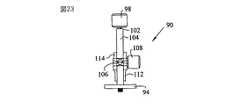
正方形のアライメントロッド80を遠位テレスコープロッド90の細長い正方形のアライメントロッド穴92(図24)内に挿入する前に、足関節120(図25〜図27)が遠位テレスコープロッド90に接続される。図27を参照すると、足関節クランプ120は、遠位テレスコープロッド90のあり継ぎ94(図22)を受け入れるように寸法決めされたあり継ぎチャネル122を含む。図22に示したように、遠位テレスコープロッド90は、足関節クランプ120を遠位テレスコープロッド90に一時的に固定するために足関節クランプ保持ノブ98を含む。図22〜図24に示したように、足関節クランプ保持ノブ98は足関節クランプ保持ロッド102に固定され、このロッドは、足関節クランプ保持シリンダにねじ式に係合され、あり継ぎ94を通して延在する。あり継ぎ94をあり継ぎチャネル122内に配置して、足関節クランプ保持ノブ98が回転され、あり継ぎ94の底面から延在して、あり継ぎ94とあり継ぎチャネル122との間に締りばめを形成するように、足関節クランプ保持ロッド102の端部を強制する。足関節クランプ120は、模範的な一実施態様では、あり継ぎ94の下に延在する足関節クランプ保持ロッド102の端部を受け入れるためのチャネルを含むことが可能である。 Before inserting the
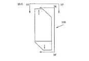
足関節クランプ120を一時的に遠位テレスコープロッド90に固定して、スプリングアーム124は、正方形のアライメントロッド80が遠位テレスコープロッド90の細長い正方形のアライメントロッド穴92内に挿入されるとき、スプリング126のバイアス力に対抗して開口され、また足関節の近位の足関節の周りに配置される。足関節クランプ120は、有利に、本発明の離間装置の冠状回転を妨げる。図19と図20に示したように、次に、丸いアライメントロッド100が、アライメントタワー70の丸いアライメントロッド穴82(図15と図18)内に挿入され、丸いアライメントロッド100の残部は図20に示したように近位に延在する。代替的実施態様では、丸いアライメントロッド100は代わりの丸いアライメントロッド穴88内に挿入される。図15と図18に示したように、代わりの丸いアライメントロッド穴88は楕円である。大きな又は太い大腿部を有する患者に本発明のアライメント装置を使用する場合に、代わりの丸いアライメントロッド穴88が利用される。次に、ターゲットガイド110が丸いアライメントロッド100の近位端に摺動され、図20に示したようなアライメント装置の組立体を完成する。アライメント装置を組み立てまた図20に示したように接続して、正方形のアライメントロッド80の第1の端部128及び丸いアライメントロッド100の第1の端部130が遠位大腿骨18’の関節丘の間に配置される。ターゲットガイド110は、より詳細に図35〜図37に示されている。図36と図37に示したように、ターゲットガイド110は丸いアライメントロッド穴132を含み、アライメント装置が図20に示したように完全に組み立てられたとき、丸いアライメントロッド100が前記ロッド穴内に配置される。図35に示したように、ターゲットガイド110は、その適切な位置決めを示す前方マーキングを含む。図35に示したように、ターゲットガイド110は、左中間/右横方向を示すマーキングを含み、これらのマーキングは、ターゲットガイドの表面を前方に配向して、左中間の単関節丘膝関節形成又は右横方向の単関節丘膝関節形成を実行する場合にターゲットガイド110が有用であることを示している。ターゲットガイド110の反対側は、右中間/左横方向を示すマーキングを含み、これらのマーキングは、反対側のマークされた表面を前方に配向して、右中間の単関節丘膝関節形成又は左横方向の単関節丘膝関節形成を実行する場合にターゲットガイド110が有用であることを示している。ターゲットガイド110の反対側に、大腿骨頭部ターゲット領域が中心の右に配置される。 With the
代わりに、調整可能なアライメントブロック38をジョイントに挿入する前に、アライメント組立体を組み立てることができる。この実施態様では、足関節クランプ120のスプリングアーム124は、スプリング126のバイアス力に対抗して、患者の足関節の周りの配置を受け入れる開位置に移動され、また調整可能なアライメントブロック38の大腿骨パドル42が、単関節丘膝関節形成を受ける膝の区画内に挿入されるときに、患者の足関節の周りに配置される。特に、アライメントタワー70は、調整可能なアライメントブロック38のアライメントタワーボス54がアライメントタワー70のボス穴72に挿入されて、またアライメント突出部74が調整可能なアライメントブロック38の基部55に当接して、調整可能なアライメントブロック38の頂部に配置することができる。アライメントタワー70を調整可能なアライメントブロック38に固定して、足関節クランプ120は遠位テレスコープロッド90のあり継ぎ94内に摺動され、足関節クランプ保持ノブ98は、足関節クランプ120を遠位テレスコープロッド90に一時的に保持するために締め付けられる。次に、正方形のアライメントロッド80の端部は遠位テレスコープロッド90に挿入され、また正方形のアライメントロッド80の第1の端部128は、アライメントタワー70の正方形のアライメントロッド穴78(図15)を通して配置される。脚アライメントを受動的に矯正して、関節は開口保持され、また調整可能なアライメントブロック38の大腿骨パドル42は冒された膝の区画内に形成された空間に挿入され、足関節クランプは足関節の上方に配置される。この時点で、スプリングアーム124は、スプリング126のバイアス力に対抗して開位置に移動されて、踝の近位の足関節の周りに配置され、アライメント装置の患者への固定を完成する。代わりに、上述のように、調整可能なアライメントブロック38の大腿骨パドル42を冒された膝の区画内に導入するのと同時に、足関節クランプを足関節の周りに固定してもよい。 Alternatively, the alignment assembly can be assembled prior to inserting the
関節アライメント
図20に示したようにアライメント装置を配置して、遠位テレスコープロッド90の中間横方向の調整を可能にするために、足関節クランプ保持ノブ98が緩められる。足関節クランプ120に対する遠位テレスコープロッド90の相対運動を可能にするために、足関節クランプ保持ノブ90を緩めて、触知可能な中間踝と横方向踝との間の中点に対し約5〜10mm中間に遠位テレスコープロッド90の遠位先端部106が位置決めされるまで、遠位先端部が移動される。本明細書に開示した中間区画関節形成では、近位先端部106は第2の中足骨を指すはずである。遠位テレスコープロッド90の近位先端部106が上述のように適切に配置されたとき、この中間横方向の位置に遠位テレスコープロッドを固定するために、足関節クランプ保持ノブ98が締め付けられる。近位に、正方形のアライメントロッドの長手方向軸線80(したがって、近位テレスコープロッド90)が、脛骨結節の中点のちょうど中間に位置し、また関節丘間の隆起の上方でセンタリングされなければならない。高さ調整ノブ108を緩め、また前方脛骨稜に対し平行になるまで正方形のアライメントロッドチューブ112、したがって、正方形のアライメントロッド80の高さを調整し、その後に高さ調整ノブ108を締め付けて近位アライメント装置を適切な位置に保持することによって、遠位テレスコープロッド90及び正方形のアライメントロッド80は、前方脛骨稜に対し平行に配置される。Joint Alignment As shown in FIG. 20, the ankle
今や、ターゲットガイド110が大腿骨頭部の中心を指すまで脚部を移動することによって、脚部は所望のアライメントに配置される。矯正しすぎは避けるべきである。中間区画の関節形成では肢を僅かに内反にアライメントし、あるいは横方向区画の関節形成では肢を僅かに外反にアライメントすることが好ましい。このことを念頭におき、ターゲットガイド110の上にマークされた大腿骨頭部のターゲット領域は、図35に示したように、丸いアライメントロッド穴132の長手方向軸線の左にオフセットされる。このオフセットは、肢アライメントにおける所望の僅かな不十分な矯正を可能にする。肢を適切にアライメントして、作動ノブ52は、図9と図7に示した閉位置から開位置(例えば、図6と図10に示した位置)に調整可能なアライメントブロック38を作動するために回転され、脛骨パドル44が近位脛骨に係合して、関節空間が充填されるときに開口は停止する。調整可能なアライメントブロック38は、関節をアライメント保持するために利用される。 Now, the leg is placed in the desired alignment by moving the leg until the
関節を適切にアライメント保持して、頭なしねじ160(例えば、図39参照)は、調整可能なアライメントブロック38の脛骨固着穴46を通して挿入されかつ脛骨12内に押し込まれ、調整可能なアライメントブロック38のねじを残す。好ましいならば、頭なしねじの代わりに頭なし保持ピンを使用することができるが、本実施態様では、ピン固定を弱める可能性があるので、挿入されるピン全長まで穿孔することなくピンを受容するために、孔を予め穿孔しなければならない。次に、頭付きねじは、調整可能なアライメントブロック38の大腿骨固着穴48を通して挿入され、遠位大腿骨18内に押し込まれる。頭付きねじは、過剰なトルク付与及びその結果として生じる骨ストックの剥ぎ取りを避けるために、大腿骨10’内に手で締め付けることが可能である。この時点において、アライメントが確認され、また変更なければ、アライメントタワー70、丸いアライメントロッド100、正方形のアライメントロッド80、遠位テレスコープロッド90、及び足関節クランプ120が取り除かれる。 With the joint properly aligned, a headless screw 160 (see, eg, FIG. 39) is inserted through the
調整可能なアライメントブロック38を大腿骨10’と脛骨12’とに固定して(例えば、図20参照)、振動又は往復運動ブレードが調整可能なアライメントブロック38の大腿骨切断スロット40を通して挿入され、近位大腿骨関節丘を切除するために利用される。模範的な一実施態様では、遠位大腿骨切断は、脛骨及び大腿骨の両方に固定された調整可能なアライメントブロック38から開始し、また大腿骨固着穴48を通して配置された頭付きねじを取り除き、膝を屈曲することによって完了される。遠位大腿骨切断が大腿骨10’と脛骨12’とに固定された調整可能なアライメントブロック38で仕上げられる場合、遠位大腿骨切除が完了した後、頭付き大腿骨ねじが大腿骨固着穴48から取り除かれる。 With
大腿骨ねじを取り除いた後、作動ノブ52を反時計回り方向に回転することによって、図7と図9に示した閉位置に向かって調整可能なアライメントブロック38が作動される。次に、調整可能なアライメントブロック38は、例えばピンプライヤで取り外され、頭なしねじ160を脛骨12’に残す。頭なしねじは、遠位大腿骨切断部と脛骨プラト切断部との間にリンクを提供する。 After removing the femoral screw, the
次に、図32〜図34に示した脛骨切断ブロック140が脛骨切除を案内するために利用される。図32に示したように、脛骨切断ブロック140は、孔対142/142’、144/144’、146/146’、及び148/148’を含む。各孔対は、調整可能なアライメントブロック38の脛骨固着穴46を通して配置された頭なしねじ160の挿入を受け入れるように離間され、上述のように脛骨12’内に残される。このようにして、孔対142/142’、144/144’、146/146’、及び148/148’は、脛骨切断部を遠位大腿骨切断部に連結するために切除スロット150に関連して使用される。図34に示したように、孔142と146の長手方向軸線は切除スロット150と3度の角度を形成し、3度の脛骨傾斜を可能にする。本発明による脛骨切断ブロックは、9度、7度、5度、又はゼロ度の脛骨傾斜を含む様々な脛骨傾斜を提供できることが考えられる。 Next, the
図32に示したように、孔対142/142’には、脛骨切断ブロック140に8のマークが付けられている。同様に、残りの孔対にはマーク10、12、及び14が付けられている。これらの孔対の番号は、脛骨補てつ移植体、すなわち脛骨部材及び軸受面のサイズに対応する。模範的な実施態様は、8、10、12、及び14とマークされた孔対を含むが、本発明による脛骨切断ブロックは、代わりの厚さの脛骨補てつ装具に対応する追加の切断深さを含み得ることが考えられる。最初に、脛骨12’から突出する頭なしねじは、8mmの脛骨関節表面、すなわち、8mmの脛骨関節表面に必要な最少の脛骨切除に対応する孔対142/142’を通して挿入される。脛骨切断ブロックの孔対を通して頭なし脛骨ねじを位置決めすることによって、膝の機械軸に対し略垂直に、また遠位大腿骨切断部に対し略平行に切除スロット150がアライメントされる。もし脛骨/頚骨傾斜を設けている脛骨切断ブロックが利用されるなら、サイズ番号は、脛骨切除の中央を参照し中央は前方から後方に、すなわちサジタル平面に含まれる線に沿って測定される。 As shown in FIG. 32, the
脛骨切断ブロック140を頭なし脛骨ねじの上方に配置した後、膝が屈曲される。皮膚の張りが脛骨切断ブロック140のアライメントに影響するならば、切り口は長くなることがある。模範的な一実施態様では、選択した脛骨切除が妥当であることを確かめるのを補助するために、切除スロット150を通して切除ガイドを挿入することができる。不十分な量の骨が切除されることを切除ガイドが示すならば、あるいはより厚い関節表面が望まれるならば、脛骨切断ブロック140を頭なし脛骨ねじとの係合から取り外し、次の孔対、すなわち孔対144/144’を用いて置き換えることができる。不十分な量の骨が切除されることを切除ガイドが示すならば、あるいはより厚い関節表面が望まれるならば、脛骨切断ブロック140を頭なし脛骨ねじとの係合から取り外し、次の孔対、すなわち孔対144/144’を用いて置き換えることができる。脛骨切除が妥当であることを確かめるのを補助するために、切除ガイドを再び利用することができ、また必要に応じて、脛骨切断ブロック140を次の孔対に再配置することができる。 After placing the
脛骨切断ブロック140が適切に配置されると、頭なし脛骨ねじ160はその孔対を通して延在し、脛骨は脛骨移植体を受容するように切除される。大腿骨を切除するとき、開創器を中間に挿入して中間側副靱帯を保護することができる。図38に示したように、脛骨12’のサジタル切断部をフリーハンドで作ることができる。膝を屈曲して、往復運動鋸154のブレード152は、冒された区画内の脛骨隆起156に隣接して配置される。図38に示したように、往復運動鋸154のブレード152は前方/後方面の脛骨隆起に対し略平行に配置される。図38に示したような位置のブレード152により、ブレード152が脛骨切断ブロック140の近位表面158と接触するまで、脛骨隆起の中間縁部に沿った脛骨内で切断が行われる。近位表面158は、サジタル切断部の前方/後方傾斜を決定するためのガイドとして利用される。脛骨切断ブロック140の近位表面158の切断により、サジタル切断部の切除されない約3〜4mmの骨が残される。脛骨切除中に、骨に対して脛骨切断ブロック140を手動で位置保持できるか、代わりに、1つ又は1対の血管鉗子を、脛骨切断ブロック140に当接する位置の頭なし脛骨ねじ160に挟持して、脛骨切断ブロック140を脛骨12’に対して面一に保持することができる。 When the
選択的に、脛骨切断ブロック140は、頭なし脛骨ねじ160の上で、サジタル切断部を作るときに水平切断のために使用される孔対の上方4mmにある孔対に再配置することが可能である。例えば、8mmの切断に対応する孔対、すなわち、孔対142/142’が適切な切除レベルであると決定されるならば、12mmの切除に対応する孔対146/146’を通して位置決めされた頭なし脛骨ねじ160で、脛骨切断ブロック140を再配置することができる。水平切断に望ましい孔の4mm上方の1対の孔に切断ブロックを再配置することにより、所望の近位切除レベルさえも得ながら、脛骨切断ブロック140の近位表面158が配置され、またサジタル切断部のための機械的ストップが提供される。開示した模範的な実施態様では、この選択は、8mm又は10mmの移植体切断深さが所望の水平切除レベルである場合にのみ利用可能であることを指摘する。 Optionally, the
図39は、脛骨切断ブロック140を脛骨12’に対して面一に固定するために、横方向の脛骨頭なしピン160に挟持された止血鉗子162を示している。図39に示したように、近位脛骨切断部を作るために振動鋸32が利用される。図39に示したように、振動鋸ブレード36は、近位脛骨切断部を作るために脛骨切断ブロック140の切除スロット150を通して挿入される。この方法で近位脛骨切断部を作る場合、脛骨隆起156の切り落としを防止するように注意を払うべきである。水平な近位脛骨切除が完了した後、脛骨切断ブロック140及び頭なし脛骨ねじ160が取り除かれる。そして、サジタル切断部が未完成である場合、この切断は完了され、切除された脛骨破片が除去される。 FIG. 39 shows
今や、残りの関節間軟骨を取り除くことができ、また調整可能なアライメントボックス38の大腿骨切断スロット40を通して作られた遠位大腿骨切断部を参照する大腿骨切断ガイドを利用して、大腿骨10’の賦形を完成することができる。今や、暫定的な大腿骨及び脛骨移植体を用いて試験的な整復が実行され、次に、最終の移植体が設置される。 The remaining inter-articular cartilage can now be removed and the femoral cutting guide referenced to the distal femoral cutting made through the
本発明の代替的実施態様では、関節と上述のアライメント装置とをアライメントし、また調整可能なアライメントブロック38の脛骨固着穴46を通して頭なし脛骨ねじ160を位置決めすることによって、しかし、調整可能なアライメントブロック38を大腿骨10’に固定するために、頭付きねじを利用せずに、脛骨切断部を最初に作ることができる。頭なし脛骨ねじ160を脛骨12’に固定して、調整可能なアライメントブロック38を含むアライメント装置が取り外され、また脛骨切断ブロック140を利用して、上述のように脛骨を切除する。脛骨切除が完成すると、調整可能なアライメントブロック38は、頭なし脛骨ねじ60(図38と図39)の上方に再配置され、肢アライメントを促進するために、アライメント装置が図20に示したように再び組み立てられる。適切な肢アライメントが達成された後、上述のように調整可能なアライメントブロック38の大腿骨固着穴48を通して、頭付きの大腿骨ねじが配置され、また上述のように大腿骨切断スロット40を通して遠位大腿骨が切除される。 In an alternative embodiment of the present invention, the alignment is performed by aligning the joint with the alignment device described above and positioning the
模範的な構造を有するものとして本発明について記述してきたが、本開示の精神及び範囲内で本発明をさらに修正することが可能である。したがって、本出願は、任意の変形、用途、あるいは本発明の一般的な原理を利用する本発明の適応を網羅することが意図される。さらに、本出願は、関連技術において公知又は慣習的な本発明が関係する実用に含まれるような本発明の開示からの逸脱を網羅することが意図される。 While this invention has been described as having an exemplary structure, the present invention can be further modified within the spirit and scope of this disclosure. This application is therefore intended to cover any variations, uses, or adaptations of the invention using the general principles of the invention. Furthermore, this application is intended to cover any departures from the disclosure of the invention as included in the practice to which the invention pertains, known or customary in the relevant arts.
39…本体
40…大腿骨切断スロット
46…脛骨固定穴
48…大腿骨固定穴
140…脛骨切断ブロック39 ...
Claims (28)
Translated fromJapaneseスペーサを前記膝関節内に挿入するステップと、
第1の端部と第2の端部と長手方向軸線とを有する大腿骨アライメントロッドを前記スペーサに接続するステップであって、前記大腿骨アライメントロッドの第1の端部が前記大腿骨の遠位端に配置された1対の関節丘の間に配置され、かつ前記大腿骨アライメントロッドの第2の端部が前記大腿骨の大腿骨頭部に向かって近位に延在する、ステップと、
第1の端部と第2の端部とを有する脛骨アライメントロッドを前記スペーサに接続するステップであって、前記脛骨アライメントロッドの第1の端部が前記1対の関節丘の間に配置され、前記脛骨アライメントロッドの第2の端部が遠位に延在し、前記脛骨アライメントロッドが、前記大腿骨アライメントロッドに対し略平行かつ同一直線上にある、ステップと、
ターゲットガイドを前記大腿骨アライメントロッドの前記第2の端部に接続するステップであって、前記ターゲットガイドが、前記大腿骨アライメントロッドの前記長手方向軸線から基準オフセットを有するステップと、
前記ターゲットガイドの前記基準を大腿骨頭部とアライメントするステップと、
前記脛骨アライメントロッドと脛骨機械軸とをアライメントするステップと、
前記ターゲットガイドの前記基準が前記大腿骨頭部とアライメントされたままであり、かつ前記脛骨アライメントロッドが前記脛骨機械軸とアライメントされたままである位置に、膝を維持するようにスペーサを調整するステップとを含む方法。A method of performing a desired alignment between a tibia and a femur forming a knee joint having an alignment deformation comprising:
Inserting a spacer into the knee joint;
Connecting a femoral alignment rod having a first end, a second end, and a longitudinal axis to the spacer, wherein the first end of the femoral alignment rod is distal to the femur; Disposed between a pair of condyles disposed at the distal ends and a second end of the femoral alignment rod extending proximally toward the femoral head of the femur;
Connecting a tibial alignment rod having a first end and a second end to the spacer, wherein the first end of the tibial alignment rod is disposed between the pair of condyles. A second end of the tibial alignment rod extends distally and the tibial alignment rod is substantially parallel and collinear with the femoral alignment rod;
Connecting a target guide to the second end of the femoral alignment rod, the target guide having a reference offset from the longitudinal axis of the femoral alignment rod;
Aligning the reference of the target guide with a femoral head;
Aligning the tibial alignment rod with the tibial mechanical axis;
Adjusting a spacer to maintain the knee in a position where the reference of the target guide remains aligned with the femoral head and the tibial alignment rod remains aligned with the tibial mechanical axis; Including methods.
本体と、前記本体に接続された大腿骨パドルと、前記本体に接続された脛骨パドルであって、前記大腿骨パドル及び前記脛骨パドルの一方が前記本体に可動に接続される脛骨パドルとを備える調整可能なアライメントブロックを具備し、
スペーサを前記膝関節内に挿入する前記ステップが、前記調整可能なアライメントブロックの大腿骨パドル及び脛骨パドルを前記膝関節の区画内に挿入するステップを含む請求項1に記載の方法。The spacer is
A main body, a femoral paddle connected to the main body, and a tibial paddle connected to the main body, wherein one of the femoral paddle and the tibial paddle is movably connected to the main body An adjustable alignment block;
The method of claim 1, wherein the step of inserting a spacer into the knee joint includes inserting a femoral paddle and a tibial paddle of the adjustable alignment block into the knee joint compartment.
前記大腿骨パドルが前記大腿骨の遠位端に接触し、かつ前記脛骨パドルが前記脛骨の近位端と接触するまで、前記大腿骨パドル及び前記脛骨パドルの一方を移動するステップを含む請求項2に記載の方法。Adjusting the spacer to maintain the knee in a position where the femoral alignment rod remains aligned with the femoral mechanical axis and the tibial alignment rod remains aligned with the tibial mechanical axis; But,
Moving the one of the femoral paddle and the tibial paddle until the femoral paddle contacts the distal end of the femur and the tibial paddle contacts the proximal end of the tibia. 2. The method according to 2.
アライメントタワーを前記調整可能なアライメントブロックに接続するステップであって、前記アライメントタワーの端部を収容するアライメントロッドが、大腿骨の遠位端に配置された前記1対の関節丘の間に配置される、ステップと、
前記大腿骨アライメントロッドを、前記アライメントタワーの端部を収容する前記アライメントロッドに接続するステップとを含む請求項2に記載の方法。Connecting the femoral alignment rod to the spacer comprises the steps of:
Connecting an alignment tower to the adjustable alignment block, wherein an alignment rod that houses the end of the alignment tower is disposed between the pair of condyles disposed at the distal end of the femur Step,
Connecting the femoral alignment rod to the alignment rod that houses the end of the alignment tower.
アライメントタワーを前記調整可能なアライメントブロックに接続するステップであって、前記アライメントタワーの端部を収容するアライメントロッドが、大腿骨の遠位端に配置された前記1対の関節丘の間に配置される、ステップと、
前記脛骨アライメントロッドを、前記アライメントタワーの端部を収容する前記アライメントロッドに接続するステップとを含む請求項2に記載の方法。Connecting the tibial alignment rod to the adjustable alignment block comprises:
Connecting an alignment tower to the adjustable alignment block, wherein an alignment rod that houses the end of the alignment tower is disposed between the pair of condyles disposed at the distal end of the femur Step,
Connecting the tibial alignment rod to the alignment rod that houses the end of the alignment tower.
スペーサを前記膝関節内に挿入するステップと、
第1の端部と第2の端部と長手方向軸線とを有する大腿骨アライメントロッドを前記スペーサに接続するステップであって、前記大腿骨アライメントロッドの第1の端部が前記大腿骨の遠位端に配置された1対の関節丘の間に配置され、かつ前記大腿骨アライメントロッドの第2の端部が前記大腿骨の大腿骨頭部に向かって近位に延在する、ステップと、
第1の端部と第2の端部とを有する脛骨アライメントロッドを前記スペーサに接続するステップであって、前記脛骨アライメントロッドの第1の端部が前記1対の関節丘の間にアライメントされ、前記脛骨アライメントロッドの第2の端部が遠位に延在し、前記脛骨アライメントロッドが、前記大腿骨アライメントロッドに対し略平行かつ同一直線上にある、ステップと、
前記脛骨アライメントロッドと脛骨機械軸とをアライメントするステップと、
前記大腿骨アライメントロッドと大腿骨機械軸とを実質的にアライメントするステップと、
前記脛骨アライメントロッドが前記脛骨機械軸とアライメントされたままであり、かつ前記大腿骨アライメントロッドが前記大腿骨機械軸と実質的にアライメントされたままである位置に、膝を維持するように前記スペーサを調整する前記ステップとを含む方法。A method of performing a desired alignment between a tibia and a femur forming a knee joint having an alignment deformation comprising:
Inserting a spacer into the knee joint;
Connecting a femoral alignment rod having a first end, a second end, and a longitudinal axis to the spacer, wherein the first end of the femoral alignment rod is distal to the femur; Disposed between a pair of condyles disposed at the distal ends and a second end of the femoral alignment rod extending proximally toward the femoral head of the femur;
Connecting a tibial alignment rod having a first end and a second end to the spacer, wherein the first end of the tibial alignment rod is aligned between the pair of condyles. A second end of the tibial alignment rod extends distally and the tibial alignment rod is substantially parallel and collinear with the femoral alignment rod;
Aligning the tibial alignment rod with the tibial mechanical axis;
Substantially aligning the femoral alignment rod and the femoral mechanical axis;
Adjust the spacer to maintain the knee in a position where the tibial alignment rod remains aligned with the tibial mechanical axis and the femoral alignment rod remains substantially aligned with the femoral mechanical axis Comprising the steps of:
ターゲットガイドを前記大腿骨アライメントロッドの前記第2の端部に接続するステップであって、前記ターゲットガイドが、前記大腿骨アライメントロッドの前記長手方向軸線から基準オフセットを有するステップと、
前記ターゲットガイドの前記基準を大腿骨頭部とアライメントするステップとを含む請求項7に記載の方法。Substantially aligning the femoral alignment rod with a femoral mechanical axis,
Connecting a target guide to the second end of the femoral alignment rod, the target guide having a reference offset from the longitudinal axis of the femoral alignment rod;
8. The method of claim 7, comprising aligning the reference of the target guide with a femoral head.
大腿骨と脛骨とをアライメントするステップと、
前記遠位大腿骨切断部を作ることができる大腿骨切断スロットを含む前記大腿骨切断ガイドを、大腿骨に固定するステップと、
所望のアライメントを行うステップであって、前記大腿骨切断スロットに連結された基準を脛骨に固定するステップと、
前記大腿骨切断ガイドを取り除くステップと、
前記近位脛骨切断部を作ることができる脛骨切断スロットを含む前記脛骨切断ガイドを、前記基準に接続するステップであって、前記基準が前記近位脛骨切断部を遠位大腿骨切断部に連結するステップとを含む方法。A method of connecting a proximal tibial cut made with a tibial cutting guide and a distal femoral cut made with a femoral cutting guide, comprising:
Aligning the femur and tibia;
Securing the femoral cutting guide including a femoral cutting slot capable of creating the distal femoral cutting to the femur;
Performing a desired alignment comprising: fixing a reference coupled to the femoral cutting slot to the tibia;
Removing the femoral cutting guide;
Connecting the tibial cutting guide including a tibial cutting slot capable of creating the proximal tibial cut to the reference, the reference connecting the proximal tibial cut to a distal femoral cut Comprising the steps of:
大腿骨切断スロットと大腿骨固定穴と該穴内に形成された脛骨固定穴とを有する本体を備える大腿骨切断ブロックと、
前記大腿骨切断ブロックを脛骨に固定するための頭なし固定手段であって、前記大腿骨切断ブロック内の前記脛骨固定穴を横断して、前記大腿骨切断ブロックを前記脛骨に固定する頭なし固定手段と、
脛骨切断スロットと、該スロット内に形成された脛骨固定穴とを有する本体であって、前記脛骨固定穴が、それを通して前記頭なし固定手段の通路を受け入れるように寸法決めされ、前記大腿骨切断ブロックの前記脛骨固定穴が前記大腿骨切断スロットから所定の距離だけ離間され、前記顴骨切断ブロックの前記脛骨固定穴が前記脛骨切断スロットから所定の距離だけ離間され、また前記大腿骨切断スロットが前記頭なし固定手段によって前記脛骨切断スロット脛骨切断ブロックに連結される、本体を備える脛骨切断ブロックとを具備する装置。An apparatus for connecting a distal femur cut and a proximal tibial cut comprising:
A femoral cutting block comprising a body having a femoral cutting slot, a femoral fixation hole, and a tibial fixation hole formed in the hole;
A headless fixing means for fixing the femoral cutting block to the tibia, wherein the headless fixing fixes the femoral cutting block to the tibia across the tibial fixation hole in the femoral cutting block. Means,
A body having a tibial cutting slot and a tibial fixation hole formed in the slot, wherein the tibial fixation hole is dimensioned to receive a passage of the headless fixation means therethrough, the femoral cutting The tibial fixation hole of the block is spaced a predetermined distance from the femoral cutting slot, the tibial fixation hole of the rib cutting block is spaced a predetermined distance from the tibial cutting slot, and the femoral cutting slot is A tibial cutting block comprising a body coupled to the tibial cutting slot tibial cutting block by the headless fixation means.
前記大腿骨切断ブロックの前記本体から延在する大腿骨パドルと、
前記大腿骨切断ブロックの前記本体に可動に接続される脛骨パドルであって、近位の脛骨に当接するように移動され、前記膝が肢アライメントを矯正するように位置決めされるときに遠位大腿骨に当接する脛骨パドルとを備える請求項17に記載の装置。The spacing means comprises:
A femoral paddle extending from the body of the femoral cutting block;
A tibial paddle movably connected to the body of the femoral cutting block, moved to abut the proximal tibia and the distal femur when the knee is positioned to correct limb alignment 18. The apparatus of claim 17, comprising a tibial paddle that abuts against the bone.
大腿骨切断スロットを有する大腿骨切断ブロックと、
脛骨切断スロットを有する脛骨切断ブロックと、
前記大腿骨切断スロットと前記脛骨切断スロットとを連結して、膝を屈曲して前記脛骨切断スロットを通した近位脛骨切断部の作製を可能にするための手段とを具備する装置。A device for preparing a knee to receive a knee prosthesis,
A femoral cutting block having a femoral cutting slot;
A tibial cutting block having a tibial cutting slot;
Means for connecting the femoral cutting slot and the tibial cutting slot to bend a knee to allow creation of a proximal tibial cut through the tibial cutting slot.
前記大腿骨切断ブロック内に形成された脛骨固定穴と、
前記大腿骨切断ブロックを脛骨に固定するための頭なし固定手段であって、前記大腿骨切断ブロック内の前記脛骨固定穴を横断して、前記大腿骨切断ブロックを前記脛骨に固定する頭なし固定手段と、
前記脛骨切断ブロック内に形成された脛骨固定穴とを具備する請求項20に記載の装置。Means for connecting the femoral cutting slot and the tibial cutting slot;
A tibial fixation hole formed in the femoral cutting block;
A headless fixing means for fixing the femoral cutting block to the tibia, wherein the headless fixing fixes the femoral cutting block to the tibia across the tibial fixation hole in the femoral cutting block. Means,
21. The apparatus of claim 20, comprising a tibial fixation hole formed in the tibial cutting block.
本体と、
前記本体から延在する大腿骨パドルと、
前記本体に可動に接続される脛骨パドルであって、該脛骨パドルが近位の脛骨に当接するように移動され、前記膝が肢アライメントを矯正するように位置決めされるときに前記大腿骨パドルが遠位大腿骨に当接する、脛骨パドルと、
前記大腿骨パドルに着脱自在に固定される大腿骨スペーサであって、該大腿骨スペーサが前記大腿骨パドルに固定され、また膝区画内の間隔を維持して肢アライメントを矯正するように前記装置が操作自在に位置決めされるとき、前記大腿骨スペーサが前記遠位大腿骨に向かって延在する厚さを有する大腿骨スペーサとを具備する装置。A device that corrects limb alignment by maintaining spacing within the knee compartment,
The body,
A femoral paddle extending from the body;
A tibial paddle movably connected to the body, wherein the femoral paddle is moved when the tibial paddle is moved against the proximal tibia and the knee is positioned to correct limb alignment; A tibial paddle that abuts the distal femur;
A femoral spacer removably secured to the femoral paddle, wherein the femoral spacer is secured to the femoral paddle and maintains limb spacing to correct limb alignment. And a femoral spacer having a thickness that extends toward the distal femur when the femoral spacer is operably positioned.
膝の区画内に挿入するためのスペーサと、
前記スペーサに接続された、長手方向軸線を有する脛骨アライメントロッドと、
前記脛骨アライメントロッドに着脱自在に接続される踝クランプと、
前記スペーサに接続された大腿骨アライメントロッドであって、該大腿骨アライメントロッドが長手方向軸線を有し、前記脛骨アライメントロッドの前記長手方向軸線及び大腿骨アライメントロッドの前記長手方向軸線が同一直線上にありかつ平行であるアライメントロッドとを具備するアライメント装置。An alignment device for correcting limb alignment,
A spacer for insertion into the knee compartment;
A tibial alignment rod having a longitudinal axis connected to the spacer;
A heel clamp detachably connected to the tibial alignment rod;
A femoral alignment rod connected to the spacer, the femoral alignment rod having a longitudinal axis, and the longitudinal axis of the tibial alignment rod and the longitudinal axis of the femoral alignment rod are collinear An alignment device comprising an alignment rod that is in parallel with the alignment rod.
膝の区画内に挿入するためのスペーサと、
前記スペーサに接続された、長手方向軸線を有する脛骨アライメントロッドと、
前記スペーサに接続された大腿骨アライメントロッドであって、前記大腿骨アライメントロッドが長手方向軸線を有し、前記脛骨アライメントロッドの前記長手方向軸線及び大腿骨アライメントロッドの前記長手方向軸線が同一直線上にありかつ平行である、大腿骨アライメントロッドと、
前記大腿骨アライメントロッドに着脱自在に固定されるターゲットガイドであって、前記大腿骨アライメントロッドの前記長手方向軸線から基準オフセットを有するターゲットガイドとを具備するアライメント装置。
An alignment device for correcting limb alignment,
A spacer for insertion into the knee compartment;
A tibial alignment rod having a longitudinal axis connected to the spacer;
A femoral alignment rod connected to the spacer, wherein the femoral alignment rod has a longitudinal axis, and the longitudinal axis of the tibial alignment rod and the longitudinal axis of the femoral alignment rod are collinear A femoral alignment rod that is
An alignment apparatus comprising: a target guide detachably fixed to the femoral alignment rod, the target guide having a reference offset from the longitudinal axis of the femoral alignment rod.
Applications Claiming Priority (1)
| Application Number | Priority Date | Filing Date | Title |
|---|---|---|---|
| US10/305,697US7094241B2 (en) | 2002-11-27 | 2002-11-27 | Method and apparatus for achieving correct limb alignment in unicondylar knee arthroplasty |
Publications (3)
| Publication Number | Publication Date |
|---|---|
| JP2004174265Atrue JP2004174265A (en) | 2004-06-24 |
| JP2004174265A5 JP2004174265A5 (en) | 2006-11-16 |
| JP4414209B2 JP4414209B2 (en) | 2010-02-10 |
Family
ID=32298062
Family Applications (1)
| Application Number | Title | Priority Date | Filing Date |
|---|---|---|---|
| JP2003397459AExpired - Fee RelatedJP4414209B2 (en) | 2002-11-27 | 2003-11-27 | Method and apparatus for achieving correct limb alignment during monoarticular knee arthroplasty |
Country Status (7)
| Country | Link |
|---|---|
| US (3) | US7094241B2 (en) |
| EP (1) | EP1424042B1 (en) |
| JP (1) | JP4414209B2 (en) |
| AU (2) | AU2003264612B2 (en) |
| CA (1) | CA2449336A1 (en) |
| DE (1) | DE60312628T2 (en) |
| ES (1) | ES2281607T3 (en) |
Cited By (30)
| Publication number | Priority date | Publication date | Assignee | Title |
|---|---|---|---|---|
| JP2008545457A (en)* | 2005-05-17 | 2008-12-18 | バイオメット ユーケイ リミテッド | Stylus assembly |
| JP2018528008A (en)* | 2015-09-18 | 2018-09-27 | トリース メディカル コンセプツ,インコーポレイティド | Joint spacer system and method |
| US11147590B2 (en) | 2014-07-15 | 2021-10-19 | Treace Medical Concepts, Inc. | Bone positioning and cutting system and method |
| US11213333B2 (en) | 2015-08-14 | 2022-01-04 | Treace Medical Concepts, Inc. | Bone positioning and preparing guide systems and methods |
| US11583323B2 (en) | 2018-07-12 | 2023-02-21 | Treace Medical Concepts, Inc. | Multi-diameter bone pin for installing and aligning bone fixation plate while minimizing bone damage |
| US11596443B2 (en) | 2018-07-11 | 2023-03-07 | Treace Medical Concepts, Inc. | Compressor-distractor for angularly realigning bone portions |
| US11602386B2 (en) | 2015-07-14 | 2023-03-14 | Treace Medical Concepts, Inc. | Bone positioning guide |
| US11607250B2 (en) | 2019-02-13 | 2023-03-21 | Treace Medical Concepts, Inc. | Tarsal-metatarsal joint procedure utilizing compressor-distractor and instrument providing sliding surface |
| JP2023514605A (en)* | 2020-02-19 | 2023-04-06 | クロスローズ エクストリミティ システムズ リミテッド ライアビリティ カンパニー | Systems and methods for rapidus bunion repair |
| US11622797B2 (en) | 2020-01-31 | 2023-04-11 | Treace Medical Concepts, Inc. | Metatarsophalangeal joint preparation and metatarsal realignment for fusion |
| US11627954B2 (en) | 2019-08-07 | 2023-04-18 | Treace Medical Concepts, Inc. | Bi-planar instrument for bone cutting and joint realignment procedure |
| US11690659B2 (en) | 2015-08-14 | 2023-07-04 | Treace Medical Concepts, Inc. | Tarsal-metatarsal joint procedure utilizing fulcrum |
| US11786257B2 (en) | 2015-01-07 | 2023-10-17 | Treace Medical Concepts, Inc. | Bone cutting guide systems and methods |
| US11844533B2 (en) | 2015-02-18 | 2023-12-19 | Treace Medical Concepts, Inc. | Pivotable bone cutting guide useful for bone realignment and compression techniques |
| USD1011524S1 (en) | 2022-02-23 | 2024-01-16 | Treace Medical Concepts, Inc. | Compressor-distractor for the foot |
| US11889998B1 (en) | 2019-09-12 | 2024-02-06 | Treace Medical Concepts, Inc. | Surgical pin positioning lock |
| US11890039B1 (en) | 2019-09-13 | 2024-02-06 | Treace Medical Concepts, Inc. | Multi-diameter K-wire for orthopedic applications |
| US11963703B2 (en) | 2015-07-14 | 2024-04-23 | Treace Medical Concepts, Inc. | Bone cutting guide systems and methods |
| US11986251B2 (en) | 2019-09-13 | 2024-05-21 | Treace Medical Concepts, Inc. | Patient-specific osteotomy instrumentation |
| US12004789B2 (en) | 2020-05-19 | 2024-06-11 | Treace Medical Concepts, Inc. | Devices and techniques for treating metatarsus adductus |
| USD1051382S1 (en) | 2022-02-23 | 2024-11-12 | Treace Medical Concepts, Inc. | Lesser metatarsal cut guide |
| US12161371B2 (en) | 2021-01-18 | 2024-12-10 | Treace Medical Concepts, Inc. | Contoured bone plate with locking screw for bone compression, particularly across a tarsometatarsal joint |
| USD1057155S1 (en) | 2022-02-23 | 2025-01-07 | Treace Medical Concepts, Inc. | Lesser metatarsal cut guide with parallel cut faces |
| US12193683B2 (en) | 2021-05-20 | 2025-01-14 | Treace Medical Concepts, Inc. | Cut guide with integrated joint realignment features |
| USD1068077S1 (en) | 2023-02-08 | 2025-03-25 | Treace Medical Concepts, Inc. | Orthopedic rasp for preparing an intercuneiform joint |
| USD1068078S1 (en) | 2023-02-08 | 2025-03-25 | Treace Medical Concepts, Inc. | Handle for an orthopedic instrument |
| USD1075012S1 (en) | 2022-02-23 | 2025-05-13 | Treace Medical Concepts, Inc. | Metatarsal lateral release instrument |
| US12310603B2 (en) | 2021-02-18 | 2025-05-27 | Treace Medical Concepts, Inc. | System and technique for metatarsal realignment with reduced incision length |
| USD1079011S1 (en) | 2022-02-23 | 2025-06-10 | Treace Medical Concepts, Inc. | Metatarsal cut guide with parallel cut faces |
| US12440250B2 (en) | 2024-02-05 | 2025-10-14 | Treace Medical Concepts, Inc. | Multi-diameter K-wire for orthopedic applications |
Families Citing this family (114)
| Publication number | Priority date | Publication date | Assignee | Title |
|---|---|---|---|---|
| US6702821B2 (en) | 2000-01-14 | 2004-03-09 | The Bonutti 2003 Trust A | Instrumentation for minimally invasive joint replacement and methods for using same |
| US7635390B1 (en) | 2000-01-14 | 2009-12-22 | Marctec, Llc | Joint replacement component having a modular articulating surface |
| US7708741B1 (en) | 2001-08-28 | 2010-05-04 | Marctec, Llc | Method of preparing bones for knee replacement surgery |
| US8801720B2 (en) | 2002-05-15 | 2014-08-12 | Otismed Corporation | Total joint arthroplasty system |
| US7094241B2 (en) | 2002-11-27 | 2006-08-22 | Zimmer Technology, Inc. | Method and apparatus for achieving correct limb alignment in unicondylar knee arthroplasty |
| US7887542B2 (en) | 2003-01-15 | 2011-02-15 | Biomet Manufacturing Corp. | Method and apparatus for less invasive knee resection |
| US8551100B2 (en) | 2003-01-15 | 2013-10-08 | Biomet Manufacturing, Llc | Instrumentation for knee resection |
| US7789885B2 (en) | 2003-01-15 | 2010-09-07 | Biomet Manufacturing Corp. | Instrumentation for knee resection |
| US7837690B2 (en) | 2003-01-15 | 2010-11-23 | Biomet Manufacturing Corp. | Method and apparatus for less invasive knee resection |
| US20040153066A1 (en) | 2003-02-03 | 2004-08-05 | Coon Thomas M. | Apparatus for knee surgery and method of use |
| FR2852223B1 (en)* | 2003-03-11 | 2005-06-10 | Perception Raisonnement Action En Medecine | INSTRUMENT FOR TRACKING THE POSITION OF A CUTTING PLAN |
| DE50303568D1 (en)* | 2003-04-25 | 2006-07-06 | Zimmer Gmbh | Device for preparing a femoral condyle |
| JP4231813B2 (en)* | 2003-05-06 | 2009-03-04 | ツィマー ゲーエムベーハー | Traction equipment |
| WO2004112610A2 (en) | 2003-06-09 | 2004-12-29 | Vitruvian Orthopaedics, Llc | Surgical orientation device and method |
| US7559931B2 (en)* | 2003-06-09 | 2009-07-14 | OrthAlign, Inc. | Surgical orientation system and method |
| US7481814B1 (en) | 2003-07-28 | 2009-01-27 | Biomet Manufacturing Corporation | Method and apparatus for use of a mill or reamer |
| ATE289787T1 (en) | 2003-09-15 | 2005-03-15 | Zimmer Gmbh | ADJUSTMENT DEVICE |
| US20090062806A1 (en)* | 2003-11-06 | 2009-03-05 | Scott James W | Tibial preparation apparatus and method |
| US7488324B1 (en) | 2003-12-08 | 2009-02-10 | Biomet Manufacturing Corporation | Femoral guide for implanting a femoral knee prosthesis |
| US7335206B2 (en)* | 2003-12-26 | 2008-02-26 | Zimmer Technology, Inc. | Adjustable resection guide |
| US7641661B2 (en)* | 2003-12-26 | 2010-01-05 | Zimmer Technology, Inc. | Adjustable resection guide |
| US20050192588A1 (en)* | 2004-02-27 | 2005-09-01 | Garcia Daniel X. | Instrumentation and method for prosthetic knee |
| US7608079B1 (en) | 2004-03-05 | 2009-10-27 | Biomet Manufacturing Corp. | Unicondylar knee apparatus and system |
| US7993341B2 (en) | 2004-03-08 | 2011-08-09 | Zimmer Technology, Inc. | Navigated orthopaedic guide and method |
| US8114086B2 (en) | 2004-03-08 | 2012-02-14 | Zimmer Technology, Inc. | Navigated cut guide locator |
| US8167888B2 (en) | 2004-08-06 | 2012-05-01 | Zimmer Technology, Inc. | Tibial spacer blocks and femoral cutting guide |
| US7695479B1 (en) | 2005-04-12 | 2010-04-13 | Biomet Manufacturing Corp. | Femoral sizer |
| US8002777B2 (en)* | 2005-06-09 | 2011-08-23 | Biomet Manufacturing Corp. | Instrumentation and method for implanting a curved stem tibial tray |
| US7520880B2 (en) | 2006-01-09 | 2009-04-21 | Zimmer Technology, Inc. | Adjustable surgical support base with integral hinge |
| US7744600B2 (en) | 2006-01-10 | 2010-06-29 | Zimmer Technology, Inc. | Bone resection guide and method |
| US7780671B2 (en)* | 2006-01-23 | 2010-08-24 | Zimmer Technology, Inc. | Bone resection apparatus and method for knee surgery |
| US20070233138A1 (en)* | 2006-01-27 | 2007-10-04 | Zimmer Technology, Inc. | Apparatuses and methods for arthroplastic surgery |
| CA2642615A1 (en) | 2006-02-15 | 2007-08-30 | Otismed Corp | Arthroplasty jigs and related methods |
| US9808262B2 (en) | 2006-02-15 | 2017-11-07 | Howmedica Osteonics Corporation | Arthroplasty devices and related methods |
| US9173661B2 (en) | 2006-02-27 | 2015-11-03 | Biomet Manufacturing, Llc | Patient specific alignment guide with cutting surface and laser indicator |
| US9345548B2 (en) | 2006-02-27 | 2016-05-24 | Biomet Manufacturing, Llc | Patient-specific pre-operative planning |
| US10278711B2 (en) | 2006-02-27 | 2019-05-07 | Biomet Manufacturing, Llc | Patient-specific femoral guide |
| US8070752B2 (en) | 2006-02-27 | 2011-12-06 | Biomet Manufacturing Corp. | Patient specific alignment guide and inter-operative adjustment |
| US7780672B2 (en) | 2006-02-27 | 2010-08-24 | Biomet Manufacturing Corp. | Femoral adjustment device and associated method |
| US9113971B2 (en) | 2006-02-27 | 2015-08-25 | Biomet Manufacturing, Llc | Femoral acetabular impingement guide |
| US9907659B2 (en) | 2007-04-17 | 2018-03-06 | Biomet Manufacturing, Llc | Method and apparatus for manufacturing an implant |
| US8591516B2 (en) | 2006-02-27 | 2013-11-26 | Biomet Manufacturing, Llc | Patient-specific orthopedic instruments |
| US9289253B2 (en) | 2006-02-27 | 2016-03-22 | Biomet Manufacturing, Llc | Patient-specific shoulder guide |
| US8603180B2 (en) | 2006-02-27 | 2013-12-10 | Biomet Manufacturing, Llc | Patient-specific acetabular alignment guides |
| US9339278B2 (en) | 2006-02-27 | 2016-05-17 | Biomet Manufacturing, Llc | Patient-specific acetabular guides and associated instruments |
| US20150335438A1 (en) | 2006-02-27 | 2015-11-26 | Biomet Manufacturing, Llc. | Patient-specific augments |
| US8407067B2 (en) | 2007-04-17 | 2013-03-26 | Biomet Manufacturing Corp. | Method and apparatus for manufacturing an implant |
| US9918740B2 (en) | 2006-02-27 | 2018-03-20 | Biomet Manufacturing, Llc | Backup surgical instrument system and method |
| US8323290B2 (en)* | 2006-03-03 | 2012-12-04 | Biomet Manufacturing Corp. | Tensor for use in surgical navigation |
| US7695520B2 (en) | 2006-05-31 | 2010-04-13 | Biomet Manufacturing Corp. | Prosthesis and implementation system |
| US9795399B2 (en) | 2006-06-09 | 2017-10-24 | Biomet Manufacturing, Llc | Patient-specific knee alignment guide and associated method |
| US8460302B2 (en) | 2006-12-18 | 2013-06-11 | Otismed Corporation | Arthroplasty devices and related methods |
| US20080172054A1 (en)* | 2007-01-16 | 2008-07-17 | Zimmer Technology, Inc. | Orthopedic device for securing to tissue |
| US8814874B2 (en)* | 2007-02-13 | 2014-08-26 | Medtronic Navigation, Inc. | Navigated cut guide for total knee reconstruction |
| US7959637B2 (en) | 2007-03-13 | 2011-06-14 | Biomet Manufacturing Corp. | Distal femoral cutting guide |
| US20080255573A1 (en)* | 2007-04-10 | 2008-10-16 | Zimmer, Inc. | Surgical laser trajectory instrument |
| US20090018544A1 (en)* | 2007-07-13 | 2009-01-15 | Zimmer, Inc. | Method and apparatus for soft tissue balancing |
| US8265949B2 (en) | 2007-09-27 | 2012-09-11 | Depuy Products, Inc. | Customized patient surgical plan |
| US8357111B2 (en) | 2007-09-30 | 2013-01-22 | Depuy Products, Inc. | Method and system for designing patient-specific orthopaedic surgical instruments |
| EP2194889B1 (en) | 2007-09-30 | 2015-09-23 | DePuy Products, Inc. | Customized patient-specific orthopaedic surgical instrumentation |
| US8460303B2 (en) | 2007-10-25 | 2013-06-11 | Otismed Corporation | Arthroplasty systems and devices, and related methods |
| USD642263S1 (en) | 2007-10-25 | 2011-07-26 | Otismed Corporation | Arthroplasty jig blank |
| US10582934B2 (en) | 2007-11-27 | 2020-03-10 | Howmedica Osteonics Corporation | Generating MRI images usable for the creation of 3D bone models employed to make customized arthroplasty jigs |
| US8777875B2 (en) | 2008-07-23 | 2014-07-15 | Otismed Corporation | System and method for manufacturing arthroplasty jigs having improved mating accuracy |
| US8480679B2 (en) | 2008-04-29 | 2013-07-09 | Otismed Corporation | Generation of a computerized bone model representative of a pre-degenerated state and useable in the design and manufacture of arthroplasty devices |
| US8715291B2 (en) | 2007-12-18 | 2014-05-06 | Otismed Corporation | Arthroplasty system and related methods |
| US8311306B2 (en) | 2008-04-30 | 2012-11-13 | Otismed Corporation | System and method for image segmentation in generating computer models of a joint to undergo arthroplasty |
| US8545509B2 (en) | 2007-12-18 | 2013-10-01 | Otismed Corporation | Arthroplasty system and related methods |
| US8221430B2 (en) | 2007-12-18 | 2012-07-17 | Otismed Corporation | System and method for manufacturing arthroplasty jigs |
| US8737700B2 (en) | 2007-12-18 | 2014-05-27 | Otismed Corporation | Preoperatively planning an arthroplasty procedure and generating a corresponding patient specific arthroplasty resection guide |
| US8160345B2 (en) | 2008-04-30 | 2012-04-17 | Otismed Corporation | System and method for image segmentation in generating computer models of a joint to undergo arthroplasty |
| US8617171B2 (en) | 2007-12-18 | 2013-12-31 | Otismed Corporation | Preoperatively planning an arthroplasty procedure and generating a corresponding patient specific arthroplasty resection guide |
| US8734455B2 (en) | 2008-02-29 | 2014-05-27 | Otismed Corporation | Hip resurfacing surgical guide tool |
| US20090299375A1 (en)* | 2008-06-03 | 2009-12-03 | Zimmer, Inc. | Catheter nail targeting guide |
| EP2337510B1 (en)* | 2008-06-25 | 2018-10-31 | Stryker European Holdings I, LLC | Surgical instrumentation for implanting a prothesis |
| US8617175B2 (en) | 2008-12-16 | 2013-12-31 | Otismed Corporation | Unicompartmental customized arthroplasty cutting jigs and methods of making the same |
| AU2009273863B2 (en) | 2008-07-24 | 2014-12-18 | OrthAlign, Inc. | Systems and methods for joint replacement |
| AU2009291743B2 (en) | 2008-09-10 | 2015-02-05 | Orthalign, Inc | Hip surgery systems and methods |
| US10869771B2 (en) | 2009-07-24 | 2020-12-22 | OrthAlign, Inc. | Systems and methods for joint replacement |
| US8118815B2 (en) | 2009-07-24 | 2012-02-21 | OrthAlign, Inc. | Systems and methods for joint replacement |
| US8876830B2 (en)* | 2009-08-13 | 2014-11-04 | Zimmer, Inc. | Virtual implant placement in the OR |
| AU2011341678B2 (en) | 2010-01-21 | 2014-12-11 | OrthAlign, Inc. | Systems and methods for joint replacement |
| US20110276051A1 (en)* | 2010-03-09 | 2011-11-10 | Vot, Llc | Tether and apparatus for performing a bone resection and method of use |
| USD651315S1 (en)* | 2010-05-28 | 2011-12-27 | Zimmer, Inc. | Femoral provisional prosthesis with cut guide |
| USD651313S1 (en)* | 2010-05-28 | 2011-12-27 | Zimmer, Inc. | Extramedullary telescoping tube |
| US8551108B2 (en)* | 2010-08-31 | 2013-10-08 | Orthosoft Inc. | Tool and method for digital acquisition of a tibial mechanical axis |
| US9968376B2 (en) | 2010-11-29 | 2018-05-15 | Biomet Manufacturing, Llc | Patient-specific orthopedic instruments |
| US9241745B2 (en) | 2011-03-07 | 2016-01-26 | Biomet Manufacturing, Llc | Patient-specific femoral version guide |
| CH704354B1 (en) | 2011-05-17 | 2012-07-13 | Medacta Int Sa | Equipment to align and balance the ligaments of the knee. |
| US8979847B2 (en) | 2011-06-06 | 2015-03-17 | Biomet Manufacturing, Llc | Method and apparatus for implanting a knee prosthesis |
| USD660961S1 (en)* | 2011-06-14 | 2012-05-29 | Zimmer, Inc. | Varus/valgus resection guide set |
| US8663234B2 (en) | 2011-08-01 | 2014-03-04 | Zimmer, Inc. | Combination ligament tensioner and alignment device |
| USD694884S1 (en)* | 2012-02-06 | 2013-12-03 | Zimmer, Inc. | Cut guide |
| US9549742B2 (en) | 2012-05-18 | 2017-01-24 | OrthAlign, Inc. | Devices and methods for knee arthroplasty |
| US9649160B2 (en) | 2012-08-14 | 2017-05-16 | OrthAlign, Inc. | Hip replacement navigation system and method |
| US9402637B2 (en) | 2012-10-11 | 2016-08-02 | Howmedica Osteonics Corporation | Customized arthroplasty cutting guides and surgical methods using the same |
| CN105392450B (en) | 2013-03-15 | 2017-09-29 | 马科外科公司 | Tibial knee list condyle implant |
| EP2967671B1 (en) | 2013-03-15 | 2021-11-17 | Biomet C.V. | Polyaxial pivot housing for external fixation system |
| US9408557B2 (en)* | 2013-03-18 | 2016-08-09 | Orthosensor Inc. | System and method to change a contact point of the muscular-skeletal system |
| US10363149B2 (en) | 2015-02-20 | 2019-07-30 | OrthAlign, Inc. | Hip replacement navigation system and method |
| US10751189B2 (en)* | 2016-10-12 | 2020-08-25 | Corentec Co., Ltd | Resection guide, trial knee joint implant, and surgical instrument for knee arthroplasty |
| GB2558543A (en) | 2016-12-05 | 2018-07-18 | James Hamilton Murray Brown | Apparatus for alignment of knee arthroplasty tibial cutting block |
| CN106725744B (en)* | 2017-01-24 | 2023-11-10 | 丽水市人民医院 | Infrapatellar fat pad resection device and method of use thereof |
| US10722310B2 (en) | 2017-03-13 | 2020-07-28 | Zimmer Biomet CMF and Thoracic, LLC | Virtual surgery planning system and method |
| EP3595554A4 (en) | 2017-03-14 | 2021-01-06 | OrthAlign, Inc. | Hip replacement navigation systems and methods |
| CA3056495A1 (en) | 2017-03-14 | 2018-09-20 | OrthAlign, Inc. | Soft tissue measurement & balancing systems and methods |
| US11013607B2 (en) | 2017-09-22 | 2021-05-25 | Encore Medical, L.P. | Talar ankle implant |
| US10987171B2 (en)* | 2017-11-10 | 2021-04-27 | Smith & Nephew, Inc. | Orthopedic systems, components, and methods |
| US10159494B1 (en) | 2017-12-18 | 2018-12-25 | Alexander Sah | Knee surgery guide and method |
| EP3501432A1 (en) | 2017-12-20 | 2019-06-26 | Stryker European Holdings I, LLC | Joint instrumentation |
| US11051829B2 (en) | 2018-06-26 | 2021-07-06 | DePuy Synthes Products, Inc. | Customized patient-specific orthopaedic surgical instrument |
| US12245819B2 (en) | 2018-09-19 | 2025-03-11 | Mako Surgical Corp. | Method of surgery |
| US11701130B2 (en) | 2021-06-11 | 2023-07-18 | Optimotion Implants LLC | Arthroplasty balance and gap gauge and cutting guidance |
| US11751884B2 (en) | 2021-06-11 | 2023-09-12 | Optimotion Implants LLC | Arthroplasty balance and gap gauge and cutting guidance |
Family Cites Families (149)
| Publication number | Priority date | Publication date | Assignee | Title |
|---|---|---|---|---|
| US2697433A (en) | 1951-12-04 | 1954-12-21 | Max A Zehnder | Device for accurately positioning and guiding guide wires used in the nailing of thefemoral neck |
| US3532088A (en) | 1966-02-23 | 1970-10-06 | Bio Analytical Labor Inc | Speculum instrument |
| US4349018A (en) | 1980-12-29 | 1982-09-14 | Chambers Gary R | Osteotomy apparatus |
| US4567885A (en)* | 1981-11-03 | 1986-02-04 | Androphy Gary W | Triplanar knee resection system |
| US4738253A (en)* | 1981-12-31 | 1988-04-19 | Biomedical Engineering Trust | Guides for inclined surgical cuts or resections |
| US4524766A (en) | 1982-01-07 | 1985-06-25 | Petersen Thomas D | Surgical knee alignment method and system |
| US4646729A (en)* | 1982-02-18 | 1987-03-03 | Howmedica, Inc. | Prosthetic knee implantation |
| US4825857A (en) | 1982-02-18 | 1989-05-02 | Howmedica, Inc. | Prosthetic knee implantation |
| US4457307A (en)* | 1982-08-20 | 1984-07-03 | Stillwell William T | Bone cutting device for total knee replacement |
| NZ205096A (en) | 1982-09-10 | 1986-03-14 | Univ Kingston | Mounting apparatus for bone cutting device |
| US4567886A (en) | 1983-01-06 | 1986-02-04 | Petersen Thomas D | Flexion spacer guide for fitting a knee prosthesis |
| US4566448A (en) | 1983-03-07 | 1986-01-28 | Rohr Jr William L | Ligament tensor and distal femoral resector guide |
| US4574794A (en)* | 1984-06-01 | 1986-03-11 | Queen's University At Kingston | Orthopaedic bone cutting jig and alignment device |
| US4787383A (en) | 1985-12-19 | 1988-11-29 | Howmedica, Inc. | Prosthetic knee implantation |
| US4759350A (en)* | 1986-10-17 | 1988-07-26 | Dunn Harold K | Instruments for shaping distal femoral and proximal tibial surfaces |
| US5250050A (en)* | 1987-02-07 | 1993-10-05 | Pfizer Hospital Products Group, Inc. | Apparatus for knee prosthesis |
| US5116338A (en) | 1988-02-03 | 1992-05-26 | Pfizer Hospital Products Group, Inc. | Apparatus for knee prosthesis |
| US5002547A (en) | 1987-02-07 | 1991-03-26 | Pfizer Hospital Products Group, Inc. | Apparatus for knee prosthesis |
| US4841975A (en) | 1987-04-15 | 1989-06-27 | Cemax, Inc. | Preoperative planning of bone cuts and joint replacement using radiant energy scan imaging |
| US4938762A (en) | 1987-12-16 | 1990-07-03 | Protek Ag | Reference system for implantation of condylar total knee prostheses |
| EP0326768A3 (en) | 1988-02-01 | 1991-01-23 | Faro Medical Technologies Inc. | Computer-aided surgery apparatus |
| US5251127A (en) | 1988-02-01 | 1993-10-05 | Faro Medical Technologies Inc. | Computer-aided surgery apparatus |
| US5007936A (en) | 1988-02-18 | 1991-04-16 | Cemax, Inc. | Surgical method for hip joint replacement |
| US4952213A (en) | 1989-02-03 | 1990-08-28 | Boehringer Mannheim Corporation | Tibial cutting guide |
| FR2648699B1 (en) | 1989-06-26 | 1993-06-18 | Matco | VERSATILE VIEWFINDER FOR TOTAL SLIDING KNEE PROSTHESIS |
| US5122144A (en) | 1989-09-26 | 1992-06-16 | Kirschner Medical Corporation | Method and instrumentation for unicompartmental total knee arthroplasty |
| US5234433A (en) | 1989-09-26 | 1993-08-10 | Kirschner Medical Corporation | Method and instrumentation for unicompartmental total knee arthroplasty |
| DE69026196T2 (en) | 1989-11-08 | 1996-09-05 | George S Allen | Mechanical arm for an interactive, image-controlled, surgical system |
| US5007912A (en)* | 1990-05-30 | 1991-04-16 | Albrektsson Bjoern | Arrangement for fixing a knee-joint in defined positions and for positional control of instruments for replacing the knee-joint with a prosthesis |
| FR2679766B1 (en) | 1991-07-30 | 1998-08-28 | Sophia Med | DEVICE FOR LAYING A KNEE PROSTHESIS. |
| US5514143A (en) | 1991-11-27 | 1996-05-07 | Apogee Medical Products, Inc. | Apparatus and method for use during surgery |
| EP0551572B1 (en) | 1991-12-10 | 1998-12-30 | Bristol-Myers Squibb Company | Tibial resector guide |
| US5681320A (en) | 1991-12-13 | 1997-10-28 | Mcguire; David A. | Bone-cutting guide |
| US5213112A (en) | 1992-01-29 | 1993-05-25 | Pfizer Hospital Products Group, Inc. | Tension meter for orthopedic surgery |
| US5344423A (en) | 1992-02-06 | 1994-09-06 | Zimmer, Inc. | Apparatus and method for milling bone |
| US5275603A (en) | 1992-02-20 | 1994-01-04 | Wright Medical Technology, Inc. | Rotationally and angularly adjustable tibial cutting guide and method of use |
| US5258032A (en) | 1992-04-03 | 1993-11-02 | Bertin Kim C | Knee prosthesis provisional apparatus and resection guide and method of use in knee replacement surgery |
| US5342368A (en) | 1992-07-08 | 1994-08-30 | Petersen Thomas D | Intramedullary universal proximal tibial resector guide |
| US5364401A (en) | 1992-10-08 | 1994-11-15 | Wright Medical Technology, Inc. | External alignment system for preparing a femur for an implant |
| US5551429A (en) | 1993-02-12 | 1996-09-03 | Fitzpatrick; J. Michael | Method for relating the data of an image space to physical space |
| US5474559A (en) | 1993-07-06 | 1995-12-12 | Zimmer, Inc. | Femoral milling instrumentation for use in total knee arthroplasty with optional cutting guide attachment |
| CA2126627C (en) | 1993-07-06 | 2005-01-25 | Kim C. Bertin | Femoral milling instrumentation for use in total knee arthroplasty with optional cutting guide attachment |
| US5368552A (en) | 1993-07-13 | 1994-11-29 | Rocky Mountain Prosthetics Orthotics | Orthotic hip brace |
| US5364402A (en) | 1993-07-29 | 1994-11-15 | Intermedics Orthopedics, Inc. | Tibial spacer saw guide |
| US5451228A (en) | 1993-09-14 | 1995-09-19 | Zimmer, Inc. | Tibial resector guide |
| US5601566A (en)* | 1994-02-22 | 1997-02-11 | Osteonics Corp. | Method and apparatus for the alignment of a femoral knee prosthesis |
| US5527316A (en) | 1994-02-23 | 1996-06-18 | Stone; Kevin T. | Surgical reamer |
| US5484446A (en) | 1994-06-27 | 1996-01-16 | Zimmer, Inc. | Alignment guide for use in orthopaedic surgery |
| DE4423717C1 (en) | 1994-07-08 | 1996-01-04 | Eska Medical Gmbh & Co | Device for determining resection surfaces on the femur and on the tibia for preparing an implantation of a total knee joint endoprosthesis |
| US5597379A (en) | 1994-09-02 | 1997-01-28 | Hudson Surgical Design, Inc. | Method and apparatus for femoral resection alignment |
| US5643272A (en) | 1994-09-02 | 1997-07-01 | Hudson Surgical Design, Inc. | Method and apparatus for tibial resection |
| US6695848B2 (en)* | 1994-09-02 | 2004-02-24 | Hudson Surgical Design, Inc. | Methods for femoral and tibial resection |
| US5755803A (en) | 1994-09-02 | 1998-05-26 | Hudson Surgical Design | Prosthetic implant |
| US5810827A (en) | 1994-09-02 | 1998-09-22 | Hudson Surgical Design, Inc. | Method and apparatus for bony material removal |
| US5514139A (en) | 1994-09-02 | 1996-05-07 | Hudson Surgical Design, Inc. | Method and apparatus for femoral resection |
| ATE228338T1 (en) | 1994-10-07 | 2002-12-15 | Univ St Louis | SURGICAL NAVIGATION ARRANGEMENT INCLUDING REFERENCE AND LOCATION SYSTEMS |
| FR2726178B1 (en) | 1994-10-27 | 1997-03-28 | Impact | FEMALE ANCILLARY INSTRUMENTATION FOR THE IMPLANTATION OF A UNICOMPARTMENTAL KNEE PROSTHESIS |
| US5540696A (en)* | 1995-01-06 | 1996-07-30 | Zimmer, Inc. | Instrumentation for use in orthopaedic surgery |
| US5611802A (en) | 1995-02-14 | 1997-03-18 | Samuelson; Kent M. | Method and apparatus for resecting bone |
| US5683397A (en) | 1995-02-15 | 1997-11-04 | Smith & Nephew, Inc. | Distal femoral cutting guide apparatus for use in knee joint replacement surgery |
| US5562674A (en) | 1995-02-27 | 1996-10-08 | Zimmer, Inc. | Intramedullary rod with guide member locator |
| US5593411A (en) | 1995-03-13 | 1997-01-14 | Zimmer, Inc. | Orthopaedic milling guide for milling intersecting planes |
| US6077270A (en) | 1995-05-31 | 2000-06-20 | Katz; Lawrence | Method and apparatus for locating bone cuts at the distal condylar femur region to receive a femoral prothesis and to coordinate tibial and patellar resection and replacement with femoral resection and replacement |
| US5628750A (en) | 1995-06-30 | 1997-05-13 | U.S. Medical Products, Inc. | Tibial resection guide alignment apparatus and method |
| US5735904A (en) | 1995-07-05 | 1998-04-07 | Pappas; Michael J. | Spacer for establishng prosthetic gap and ligamentous tension |
| US5601563A (en)* | 1995-08-25 | 1997-02-11 | Zimmer, Inc. | Orthopaedic milling template with attachable cutting guide |
| US5825857A (en)* | 1995-09-13 | 1998-10-20 | Mci Communications Corporation | Method and system for calling card validation hubbing |
| US5776201A (en) | 1995-10-02 | 1998-07-07 | Johnson & Johnson Professional, Inc. | Modular femoral trial system |
| GB2306653B (en) | 1995-10-23 | 1999-12-15 | Finsbury | Surgical tool |
| US5716361A (en) | 1995-11-02 | 1998-02-10 | Masini; Michael A. | Bone cutting guides for use in the implantation of prosthetic joint components |
| US5704941A (en) | 1995-11-03 | 1998-01-06 | Osteonics Corp. | Tibial preparation apparatus and method |
| US5682886A (en) | 1995-12-26 | 1997-11-04 | Musculographics Inc | Computer-assisted surgical system |
| US5669914A (en) | 1996-02-16 | 1997-09-23 | Board Of Regents Of The University Of Colorado | Rotation alignment instrument |
| US6167145A (en) | 1996-03-29 | 2000-12-26 | Surgical Navigation Technologies, Inc. | Bone navigation system |
| GB9611074D0 (en) | 1996-05-28 | 1996-07-31 | Howmedica | Surgical apparatus |
| US5681316A (en) | 1996-08-22 | 1997-10-28 | Johnson & Johnson Professional, Inc. | Tibial resection guide |
| US5980535A (en) | 1996-09-30 | 1999-11-09 | Picker International, Inc. | Apparatus for anatomical tracking |
| US5824085A (en) | 1996-09-30 | 1998-10-20 | Integrated Surgical Systems, Inc. | System and method for cavity generation for surgical planning and initial placement of a bone prosthesis |
| US5788700A (en)* | 1996-10-30 | 1998-08-04 | Osteonics Corp. | Apparatus and method for the alignment of a total knee prosthesis |
| AU737097B2 (en)* | 1997-01-28 | 2001-08-09 | New York Society For The Relief Of The Ruptured And Crippled, Maintaining The Hospital For Special Surgery | Method and apparatus for femoral resection |
| US6090114A (en)* | 1997-02-10 | 2000-07-18 | Stryker Howmedica Osteonics Corp. | Tibial plateau resection guide |
| US5810824A (en)* | 1997-02-13 | 1998-09-22 | Chan; Kwan-Ho | Surgical fastener assembly and method for bone fracture fixation |
| US5880976A (en) | 1997-02-21 | 1999-03-09 | Carnegie Mellon University | Apparatus and method for facilitating the implantation of artificial components in joints |
| US5921992A (en) | 1997-04-11 | 1999-07-13 | Radionics, Inc. | Method and system for frameless tool calibration |
| US5860980A (en) | 1997-09-15 | 1999-01-19 | Axelson, Jr.; Stuart L. | Surgical apparatus for use in total knee arthroplasty and surgical methods for using said apparatus |
| FR2776176B1 (en) | 1998-03-20 | 2000-08-18 | Aesculap Sa | SYSTEM FOR POSITIONING A BONE CUTTING GUIDE FOR THE PREPARATION FOR LAYING A KNEE PROSTHESIS |
| US6396939B1 (en) | 1998-05-28 | 2002-05-28 | Orthosoft Inc. | Method and system for segmentation of medical images |
| ATE272365T1 (en) | 1998-05-28 | 2004-08-15 | Orthosoft Inc | INTERACTIVE AND COMPUTER-ASSISTED SURGICAL SYSTEM |
| AU755664B2 (en) | 1998-06-29 | 2002-12-19 | Plus Endoprothetik Ag | Device and method for inserting a prosthetic knee |
| US6477400B1 (en) | 1998-08-20 | 2002-11-05 | Sofamor Danek Holdings, Inc. | Fluoroscopic image guided orthopaedic surgery system with intraoperative registration |
| US6033415A (en) | 1998-09-14 | 2000-03-07 | Integrated Surgical Systems | System and method for performing image directed robotic orthopaedic procedures without a fiducial reference system |
| US6430434B1 (en) | 1998-12-14 | 2002-08-06 | Integrated Surgical Systems, Inc. | Method for determining the location and orientation of a bone for computer-assisted orthopedic procedures using intraoperatively attached markers |
| US6285902B1 (en) | 1999-02-10 | 2001-09-04 | Surgical Insights, Inc. | Computer assisted targeting device for use in orthopaedic surgery |
| US6051016A (en) | 1999-03-29 | 2000-04-18 | Instrumed, Inc. | System and method of controlling pressure in a surgical tourniquet |
| US6059831A (en)* | 1999-03-31 | 2000-05-09 | Biomet, Inc. | Method of implanting a uni-condylar knee prosthesis |
| FR2791549B1 (en) | 1999-04-01 | 2001-05-25 | Aesculap Sa | DEVICE FOR POSITIONING A PROXIMAL END OF A TIBIA RELATIVE TO A CUTTING GUIDE, INCLUDING AN ADJUSTMENT HANDLE |
| US6235038B1 (en) | 1999-10-28 | 2001-05-22 | Medtronic Surgical Navigation Technologies | System for translation of electromagnetic and optical localization systems |
| ES2553715T3 (en) | 2000-03-10 | 2015-12-11 | Smith & Nephew, Inc. | Apparatus for use in arthroplasty in a knee joint |
| AU2001250538A1 (en) | 2000-04-27 | 2001-11-20 | Finsbury (Development) Limited | Surgical tool |
| US6478799B1 (en) | 2000-06-29 | 2002-11-12 | Richard V. Williamson | Instruments and methods for use in performing knee surgery |
| US6296646B1 (en) | 2000-06-29 | 2001-10-02 | Richard V. Williamson | Instruments and methods for use in performing knee surgery |
| EP1190676B1 (en) | 2000-09-26 | 2003-08-13 | BrainLAB AG | Device for determining the position of a cutting guide |
| US6613052B1 (en)* | 2000-12-21 | 2003-09-02 | J. Gregory Kinnett | Multi-functional orthopedic surgical instrument and method of using same |
| NL1017064C2 (en) | 2001-01-09 | 2002-07-16 | Fedan N B N V | Device for the implantation of knee prostheses with increased alignment accuracy between tibia and thigh. |
| GB0101990D0 (en) | 2001-01-25 | 2001-03-14 | Finsbury Dev Ltd | Surgical system |
| US6514259B2 (en)* | 2001-02-02 | 2003-02-04 | Carnegie Mellon University | Probe and associated system and method for facilitating planar osteotomy during arthoplasty |
| US7547307B2 (en) | 2001-02-27 | 2009-06-16 | Smith & Nephew, Inc. | Computer assisted knee arthroplasty instrumentation, systems, and processes |
| US7909831B2 (en) | 2001-02-28 | 2011-03-22 | Howmedica Osteonics Corp. | Systems used in performing femoral and tibial resection in knee surgery |
| US6595997B2 (en) | 2001-02-28 | 2003-07-22 | Howmedica Osteonics Corp. | Methods used in performing femoral and tibial resection in knee surgery |
| US6685711B2 (en) | 2001-02-28 | 2004-02-03 | Howmedica Osteonics Corp. | Apparatus used in performing femoral and tibial resection in knee surgery |
| US20020133162A1 (en) | 2001-03-17 | 2002-09-19 | Axelson Stuart L. | Tools used in performing femoral and tibial resection in knee surgery |
| US6770077B2 (en) | 2001-05-21 | 2004-08-03 | Nemco Medical, Ltd. | Femoral knee saw guide and method |
| US6632225B2 (en) | 2001-06-20 | 2003-10-14 | Zimmer, Inc. | Method and apparatus for resecting a distal femur and a proximal tibia in preparation for implanting a partial knee prosthesis |
| FR2826254B1 (en) | 2001-06-25 | 2004-06-18 | Aesculap Sa | DEVICE FOR POSITIONING A CUTTING PLAN OF A BONE CUTTING GUIDE |
| GB0119540D0 (en) | 2001-08-10 | 2001-10-03 | Depuy Int Ltd | Tibial resection guide |
| US7618421B2 (en) | 2001-10-10 | 2009-11-17 | Howmedica Osteonics Corp. | Tools for femoral resection in knee surgery |
| US7141053B2 (en) | 2001-11-28 | 2006-11-28 | Wright Medical Technology, Inc. | Methods of minimally invasive unicompartmental knee replacement |
| DE20202615U1 (en) | 2002-02-20 | 2002-06-06 | Aesculap AG & Co. KG, 78532 Tuttlingen | Template for guiding a surgical processing tool |
| US6758850B2 (en)* | 2002-03-29 | 2004-07-06 | Depuy Orthopaedics, Inc. | Instruments and methods for flexion gap adjustment |
| US6962593B2 (en) | 2002-06-04 | 2005-11-08 | Zimmer Technology, Inc. | Two-piece cut block for minimally invasive surgical procedure |
| US6797006B2 (en) | 2002-06-18 | 2004-09-28 | Zimmer Technology, Inc. | Porous unicondylar knee |
| US7329260B2 (en)* | 2002-06-28 | 2008-02-12 | Depuy Products, Inc. | Kit, guide and method for locating distal femoral resection plane |
| AU2003258434B8 (en) | 2002-08-23 | 2009-03-05 | Orthosoft Ulc | Total knee replacement surgery system |
| US20040039396A1 (en) | 2002-08-23 | 2004-02-26 | Orthosoft Inc. | Universal positioning block |
| US7736368B2 (en) | 2002-08-23 | 2010-06-15 | Orthosoft Inc. | Surgical universal positioning block and tool guide |
| US7094241B2 (en) | 2002-11-27 | 2006-08-22 | Zimmer Technology, Inc. | Method and apparatus for achieving correct limb alignment in unicondylar knee arthroplasty |
| US20040122305A1 (en) | 2002-12-20 | 2004-06-24 | Grimm James E. | Surgical instrument and method of positioning same |
| US7029477B2 (en) | 2002-12-20 | 2006-04-18 | Zimmer Technology, Inc. | Surgical instrument and positioning method |
| US7789885B2 (en)* | 2003-01-15 | 2010-09-07 | Biomet Manufacturing Corp. | Instrumentation for knee resection |
| US7458977B2 (en) | 2003-02-04 | 2008-12-02 | Zimmer Technology, Inc. | Surgical navigation instrument useful in marking anatomical structures |
| US20040152955A1 (en) | 2003-02-04 | 2004-08-05 | Mcginley Shawn E. | Guidance system for rotary surgical instrument |
| US7235080B2 (en) | 2003-02-20 | 2007-06-26 | Zimmer Technology, Inc. | Femoral reference tibial cut guide |
| DE20303498U1 (en) | 2003-02-26 | 2003-07-03 | Aesculap AG & Co. KG, 78532 Tuttlingen | Surgical adjusting and holding device for tool guiding arrangement, in particular for performance of operation at femur or tibia |
| DE50303568D1 (en) | 2003-04-25 | 2006-07-06 | Zimmer Gmbh | Device for preparing a femoral condyle |
| EP1470786B1 (en) | 2003-04-25 | 2005-10-05 | Zimmer GmbH | Device for preparation of a femoral condyle |
| US6932823B2 (en) | 2003-06-24 | 2005-08-23 | Zimmer Technology, Inc. | Detachable support arm for surgical navigation system reference array |
| ATE495706T1 (en)* | 2003-11-14 | 2011-02-15 | Smith & Nephew Inc | ADJUSTABLE SURGICAL CUTTING SYSTEMS |
| US7335206B2 (en) | 2003-12-26 | 2008-02-26 | Zimmer Technology, Inc. | Adjustable resection guide |
| US7282054B2 (en)* | 2003-12-26 | 2007-10-16 | Zimmer Technology, Inc. | Adjustable cut block |
| US7641661B2 (en) | 2003-12-26 | 2010-01-05 | Zimmer Technology, Inc. | Adjustable resection guide |
| US9814539B2 (en) | 2004-01-14 | 2017-11-14 | Puget Bioventures Llc | Methods and apparatus for conformable prosthetic implants |
| US7172599B2 (en) | 2004-03-03 | 2007-02-06 | Zimmer Technology, Inc. | Tibial sizer |
| EP1579812B1 (en) | 2004-03-24 | 2008-07-09 | Zimmer GmbH | Device for positioning a cutting guide for tibial resection |
| US8167888B2 (en) | 2004-08-06 | 2012-05-01 | Zimmer Technology, Inc. | Tibial spacer blocks and femoral cutting guide |
| US20060155293A1 (en) | 2005-01-07 | 2006-07-13 | Zimmer Technology | External rotation cut guide |
| US20060195111A1 (en) | 2005-01-25 | 2006-08-31 | Orthosoft Inc. | Universal positioning block assembly |
| US7927336B2 (en) | 2005-02-08 | 2011-04-19 | Rasmussen G Lynn | Guide assembly for guiding cuts to a femur and tibia during a knee arthroplasty |
| US20060217734A1 (en) | 2005-03-09 | 2006-09-28 | Zimmer Technology, Inc. | Femoral resection guide apparatus and method |
| US7780671B2 (en) | 2006-01-23 | 2010-08-24 | Zimmer Technology, Inc. | Bone resection apparatus and method for knee surgery |
- 2002
- 2002-11-27USUS10/305,697patent/US7094241B2/ennot_activeExpired - Lifetime
- 2003
- 2003-11-13CACA002449336Apatent/CA2449336A1/ennot_activeAbandoned
- 2003-11-27ESES03257497Tpatent/ES2281607T3/ennot_activeExpired - Lifetime
- 2003-11-27AUAU2003264612Apatent/AU2003264612B2/ennot_activeCeased
- 2003-11-27EPEP03257497Apatent/EP1424042B1/ennot_activeExpired - Lifetime
- 2003-11-27DEDE60312628Tpatent/DE60312628T2/ennot_activeExpired - Lifetime
- 2003-11-27JPJP2003397459Apatent/JP4414209B2/ennot_activeExpired - Fee Related
- 2006
- 2006-07-10USUS11/456,303patent/US7842039B2/ennot_activeExpired - Fee Related
- 2006-07-10USUS11/456,310patent/US8454616B2/ennot_activeExpired - Fee Related
- 2009
- 2009-02-10AUAU2009200501Apatent/AU2009200501B2/ennot_activeCeased
Cited By (52)
| Publication number | Priority date | Publication date | Assignee | Title |
|---|---|---|---|---|
| JP2008545457A (en)* | 2005-05-17 | 2008-12-18 | バイオメット ユーケイ リミテッド | Stylus assembly |
| US11147590B2 (en) | 2014-07-15 | 2021-10-19 | Treace Medical Concepts, Inc. | Bone positioning and cutting system and method |
| US12349941B2 (en) | 2014-07-15 | 2025-07-08 | Treace Medical Concepts, Inc. | Bone positioning and cutting system and method |
| US11771467B2 (en) | 2014-07-15 | 2023-10-03 | Treace Medical Concepts, Inc. | Bone positioning and cutting system and method |
| US11497528B2 (en) | 2014-07-15 | 2022-11-15 | Treace Medical Concepts, Inc. | Bone positioning and cutting system and method |
| US11523845B2 (en) | 2014-07-15 | 2022-12-13 | Treace Medical Concepts, Inc. | Bone positioning and cutting system and method |
| US11937849B2 (en) | 2014-07-15 | 2024-03-26 | Treace Medical Concepts, Inc. | Bone positioning and cutting system and method |
| US11786257B2 (en) | 2015-01-07 | 2023-10-17 | Treace Medical Concepts, Inc. | Bone cutting guide systems and methods |
| US12268397B2 (en) | 2015-01-07 | 2025-04-08 | Treace Medical Concepts, Inc. | Bone cutting guide systems and methods |
| US11844533B2 (en) | 2015-02-18 | 2023-12-19 | Treace Medical Concepts, Inc. | Pivotable bone cutting guide useful for bone realignment and compression techniques |
| US11602386B2 (en) | 2015-07-14 | 2023-03-14 | Treace Medical Concepts, Inc. | Bone positioning guide |
| US12102368B2 (en) | 2015-07-14 | 2024-10-01 | Treace Medical Concepts, Inc. | Bone positioning guide |
| US11963703B2 (en) | 2015-07-14 | 2024-04-23 | Treace Medical Concepts, Inc. | Bone cutting guide systems and methods |
| US11950819B2 (en) | 2015-07-14 | 2024-04-09 | Treace Medical Concepts, Inc. | Bone positioning guide |
| US12274481B2 (en) | 2015-08-14 | 2025-04-15 | Treace Medical Concepts, Inc. | Bone positioning and preparing guide systems and methods |
| US11602387B2 (en) | 2015-08-14 | 2023-03-14 | Treace Medical Concepts, Inc. | Bone positioning and preparing guide systems and methods |
| US12268428B2 (en) | 2015-08-14 | 2025-04-08 | Treace Medical Concepts, Inc. | Tarsal-metatarsal joint procedure utilizing fulcrum |
| US11690659B2 (en) | 2015-08-14 | 2023-07-04 | Treace Medical Concepts, Inc. | Tarsal-metatarsal joint procedure utilizing fulcrum |
| US11213333B2 (en) | 2015-08-14 | 2022-01-04 | Treace Medical Concepts, Inc. | Bone positioning and preparing guide systems and methods |
| US11911085B2 (en) | 2015-08-14 | 2024-02-27 | Treace Medical Concepts, Inc. | Bone positioning and preparing guide systems and methods |
| US12349927B2 (en) | 2015-09-18 | 2025-07-08 | Treace Medical Concepts, Inc. | Joint spacer systems and methods |
| JP7356479B2 (en) | 2015-09-18 | 2023-10-04 | トリース メディカル コンセプツ,インコーポレイティド | Joint spacer system and method |
| US11771443B2 (en) | 2015-09-18 | 2023-10-03 | Treace Medical Concepts, Inc. | Joint spacer systems and methods |
| US11648019B2 (en) | 2015-09-18 | 2023-05-16 | Treace Medical Concepts, Inc. | Joint spacer systems and methods |
| JP2021183268A (en)* | 2015-09-18 | 2021-12-02 | トリース メディカル コンセプツ,インコーポレイティド | Fitting spacer system and method |
| JP2018528008A (en)* | 2015-09-18 | 2018-09-27 | トリース メディカル コンセプツ,インコーポレイティド | Joint spacer system and method |
| US11596443B2 (en) | 2018-07-11 | 2023-03-07 | Treace Medical Concepts, Inc. | Compressor-distractor for angularly realigning bone portions |
| US11583323B2 (en) | 2018-07-12 | 2023-02-21 | Treace Medical Concepts, Inc. | Multi-diameter bone pin for installing and aligning bone fixation plate while minimizing bone damage |
| US12279794B2 (en) | 2019-02-13 | 2025-04-22 | Treace Medical Concepts, Inc. | Tarsal-metatarsal joint procedure utilizing compressor-distractor and instrument providing sliding surface |
| US11607250B2 (en) | 2019-02-13 | 2023-03-21 | Treace Medical Concepts, Inc. | Tarsal-metatarsal joint procedure utilizing compressor-distractor and instrument providing sliding surface |
| US11627954B2 (en) | 2019-08-07 | 2023-04-18 | Treace Medical Concepts, Inc. | Bi-planar instrument for bone cutting and joint realignment procedure |
| US12251091B2 (en) | 2019-08-07 | 2025-03-18 | Treace Medical Concepts, Inc. | Bi-planar instrument for bone cutting and joint realignment procedure |
| US11889998B1 (en) | 2019-09-12 | 2024-02-06 | Treace Medical Concepts, Inc. | Surgical pin positioning lock |
| US11890039B1 (en) | 2019-09-13 | 2024-02-06 | Treace Medical Concepts, Inc. | Multi-diameter K-wire for orthopedic applications |
| US11986251B2 (en) | 2019-09-13 | 2024-05-21 | Treace Medical Concepts, Inc. | Patient-specific osteotomy instrumentation |
| US11622797B2 (en) | 2020-01-31 | 2023-04-11 | Treace Medical Concepts, Inc. | Metatarsophalangeal joint preparation and metatarsal realignment for fusion |
| US12364522B2 (en) | 2020-01-31 | 2025-07-22 | Treace Medical Concepts, Inc. | Metatarsophalangeal joint preparation and metatarsal realignment for fusion |
| JP7639014B2 (en) | 2020-02-19 | 2025-03-04 | クロスローズ エクストリミティ システムズ リミテッド ライアビリティ カンパニー | Systems and methods for lapidus bunion repair |
| JP2023514605A (en)* | 2020-02-19 | 2023-04-06 | クロスローズ エクストリミティ システムズ リミテッド ライアビリティ カンパニー | Systems and methods for rapidus bunion repair |
| US12396770B2 (en) | 2020-05-19 | 2025-08-26 | Treace Medical Concepts, Inc. | Devices and techniques for treating metatarsus adductus |
| US12004789B2 (en) | 2020-05-19 | 2024-06-11 | Treace Medical Concepts, Inc. | Devices and techniques for treating metatarsus adductus |
| US12161371B2 (en) | 2021-01-18 | 2024-12-10 | Treace Medical Concepts, Inc. | Contoured bone plate with locking screw for bone compression, particularly across a tarsometatarsal joint |
| US12310603B2 (en) | 2021-02-18 | 2025-05-27 | Treace Medical Concepts, Inc. | System and technique for metatarsal realignment with reduced incision length |
| US12193683B2 (en) | 2021-05-20 | 2025-01-14 | Treace Medical Concepts, Inc. | Cut guide with integrated joint realignment features |
| USD1057155S1 (en) | 2022-02-23 | 2025-01-07 | Treace Medical Concepts, Inc. | Lesser metatarsal cut guide with parallel cut faces |
| USD1075012S1 (en) | 2022-02-23 | 2025-05-13 | Treace Medical Concepts, Inc. | Metatarsal lateral release instrument |
| USD1079011S1 (en) | 2022-02-23 | 2025-06-10 | Treace Medical Concepts, Inc. | Metatarsal cut guide with parallel cut faces |
| USD1011524S1 (en) | 2022-02-23 | 2024-01-16 | Treace Medical Concepts, Inc. | Compressor-distractor for the foot |
| USD1051382S1 (en) | 2022-02-23 | 2024-11-12 | Treace Medical Concepts, Inc. | Lesser metatarsal cut guide |
| USD1068078S1 (en) | 2023-02-08 | 2025-03-25 | Treace Medical Concepts, Inc. | Handle for an orthopedic instrument |
| USD1068077S1 (en) | 2023-02-08 | 2025-03-25 | Treace Medical Concepts, Inc. | Orthopedic rasp for preparing an intercuneiform joint |
| US12440250B2 (en) | 2024-02-05 | 2025-10-14 | Treace Medical Concepts, Inc. | Multi-diameter K-wire for orthopedic applications |
Also Published As
| Publication number | Publication date |
|---|---|
| EP1424042A2 (en) | 2004-06-02 |
| AU2009200501A1 (en) | 2009-02-26 |
| US7094241B2 (en) | 2006-08-22 |
| AU2009200501B2 (en) | 2011-04-14 |
| CA2449336A1 (en) | 2004-05-27 |
| US20060241637A1 (en) | 2006-10-26 |
| EP1424042A3 (en) | 2004-08-25 |
| DE60312628T2 (en) | 2007-12-06 |
| US20040102785A1 (en) | 2004-05-27 |
| JP4414209B2 (en) | 2010-02-10 |
| DE60312628D1 (en) | 2007-05-03 |
| ES2281607T3 (en) | 2007-10-01 |
| EP1424042B1 (en) | 2007-03-21 |
| US7842039B2 (en) | 2010-11-30 |
| AU2003264612B2 (en) | 2008-11-13 |
| US8454616B2 (en) | 2013-06-04 |
| US20060247647A1 (en) | 2006-11-02 |
| AU2003264612A1 (en) | 2004-06-17 |
Similar Documents
| Publication | Publication Date | Title |
|---|---|---|
| JP4414209B2 (en) | Method and apparatus for achieving correct limb alignment during monoarticular knee arthroplasty | |
| US12274452B2 (en) | Surgical kit for tibial resection and replacement | |
| US10709457B2 (en) | High tibial osteotomy guide | |
| US6632225B2 (en) | Method and apparatus for resecting a distal femur and a proximal tibia in preparation for implanting a partial knee prosthesis | |
| US9993254B2 (en) | Surgical instrumentation and methods of use for implanting a prosthesis | |
| US20240164793A1 (en) | Implants, devices, systems, kits and methods of implanting | |
| US9237952B2 (en) | Total knee arthroplasty system and method | |
| KR102140052B1 (en) | Osteotomy device with an in-vitro alignment component | |
| US7935120B2 (en) | Posterior femur rough cut guide for minimally invasive knee arthroplasty |
Legal Events
| Date | Code | Title | Description |
|---|---|---|---|
| A521 | Request for written amendment filed | Free format text:JAPANESE INTERMEDIATE CODE: A523 Effective date:20060928 | |
| A621 | Written request for application examination | Free format text:JAPANESE INTERMEDIATE CODE: A621 Effective date:20060928 | |
| A131 | Notification of reasons for refusal | Free format text:JAPANESE INTERMEDIATE CODE: A131 Effective date:20090623 | |
| A521 | Request for written amendment filed | Free format text:JAPANESE INTERMEDIATE CODE: A523 Effective date:20090918 | |
| TRDD | Decision of grant or rejection written | ||
| A01 | Written decision to grant a patent or to grant a registration (utility model) | Free format text:JAPANESE INTERMEDIATE CODE: A01 Effective date:20091020 | |
| A01 | Written decision to grant a patent or to grant a registration (utility model) | Free format text:JAPANESE INTERMEDIATE CODE: A01 | |
| A61 | First payment of annual fees (during grant procedure) | Free format text:JAPANESE INTERMEDIATE CODE: A61 Effective date:20091119 | |
| FPAY | Renewal fee payment (event date is renewal date of database) | Free format text:PAYMENT UNTIL: 20121127 Year of fee payment:3 | |
| R150 | Certificate of patent or registration of utility model | Ref document number:4414209 Country of ref document:JP Free format text:JAPANESE INTERMEDIATE CODE: R150 Free format text:JAPANESE INTERMEDIATE CODE: R150 | |
| FPAY | Renewal fee payment (event date is renewal date of database) | Free format text:PAYMENT UNTIL: 20121127 Year of fee payment:3 | |
| FPAY | Renewal fee payment (event date is renewal date of database) | Free format text:PAYMENT UNTIL: 20131127 Year of fee payment:4 | |
| R250 | Receipt of annual fees | Free format text:JAPANESE INTERMEDIATE CODE: R250 | |
| R250 | Receipt of annual fees | Free format text:JAPANESE INTERMEDIATE CODE: R250 | |
| R250 | Receipt of annual fees | Free format text:JAPANESE INTERMEDIATE CODE: R250 | |
| R250 | Receipt of annual fees | Free format text:JAPANESE INTERMEDIATE CODE: R250 | |
| R250 | Receipt of annual fees | Free format text:JAPANESE INTERMEDIATE CODE: R250 | |
| R250 | Receipt of annual fees | Free format text:JAPANESE INTERMEDIATE CODE: R250 | |
| R250 | Receipt of annual fees | Free format text:JAPANESE INTERMEDIATE CODE: R250 | |
| R250 | Receipt of annual fees | Free format text:JAPANESE INTERMEDIATE CODE: R250 | |
| R250 | Receipt of annual fees | Free format text:JAPANESE INTERMEDIATE CODE: R250 | |
| LAPS | Cancellation because of no payment of annual fees |