JP2004174008A - Endoscope information system, endoscope and program - Google Patents
Endoscope information system, endoscope and programDownload PDFInfo
- Publication number
- JP2004174008A JP2004174008AJP2002344900AJP2002344900AJP2004174008AJP 2004174008 AJP2004174008 AJP 2004174008AJP 2002344900 AJP2002344900 AJP 2002344900AJP 2002344900 AJP2002344900 AJP 2002344900AJP 2004174008 AJP2004174008 AJP 2004174008A
- Authority
- JP
- Japan
- Prior art keywords
- endoscope
- scope
- information
- history
- estimation
- Prior art date
- Legal status (The legal status is an assumption and is not a legal conclusion. Google has not performed a legal analysis and makes no representation as to the accuracy of the status listed.)
- Pending
Links
Images


Classifications
- A—HUMAN NECESSITIES
- A61—MEDICAL OR VETERINARY SCIENCE; HYGIENE
- A61B—DIAGNOSIS; SURGERY; IDENTIFICATION
- A61B1/00—Instruments for performing medical examinations of the interior of cavities or tubes of the body by visual or photographical inspection, e.g. endoscopes; Illuminating arrangements therefor
- A61B1/00002—Operational features of endoscopes
- A61B1/00059—Operational features of endoscopes provided with identification means for the endoscope
- A—HUMAN NECESSITIES
- A61—MEDICAL OR VETERINARY SCIENCE; HYGIENE
- A61B—DIAGNOSIS; SURGERY; IDENTIFICATION
- A61B1/00—Instruments for performing medical examinations of the interior of cavities or tubes of the body by visual or photographical inspection, e.g. endoscopes; Illuminating arrangements therefor
- A61B1/00002—Operational features of endoscopes
- A61B1/00004—Operational features of endoscopes characterised by electronic signal processing
- A61B1/00006—Operational features of endoscopes characterised by electronic signal processing of control signals
- G—PHYSICS
- G06—COMPUTING OR CALCULATING; COUNTING
- G06Q—INFORMATION AND COMMUNICATION TECHNOLOGY [ICT] SPECIALLY ADAPTED FOR ADMINISTRATIVE, COMMERCIAL, FINANCIAL, MANAGERIAL OR SUPERVISORY PURPOSES; SYSTEMS OR METHODS SPECIALLY ADAPTED FOR ADMINISTRATIVE, COMMERCIAL, FINANCIAL, MANAGERIAL OR SUPERVISORY PURPOSES, NOT OTHERWISE PROVIDED FOR
- G06Q30/00—Commerce
- G06Q30/01—Customer relationship services
- G06Q30/015—Providing customer assistance, e.g. assisting a customer within a business location or via helpdesk
- G06Q30/016—After-sales
- G—PHYSICS
- G16—INFORMATION AND COMMUNICATION TECHNOLOGY [ICT] SPECIALLY ADAPTED FOR SPECIFIC APPLICATION FIELDS
- G16H—HEALTHCARE INFORMATICS, i.e. INFORMATION AND COMMUNICATION TECHNOLOGY [ICT] SPECIALLY ADAPTED FOR THE HANDLING OR PROCESSING OF MEDICAL OR HEALTHCARE DATA
- G16H40/00—ICT specially adapted for the management or administration of healthcare resources or facilities; ICT specially adapted for the management or operation of medical equipment or devices
- G16H40/40—ICT specially adapted for the management or administration of healthcare resources or facilities; ICT specially adapted for the management or operation of medical equipment or devices for the management of medical equipment or devices, e.g. scheduling maintenance or upgrades
- G—PHYSICS
- G16—INFORMATION AND COMMUNICATION TECHNOLOGY [ICT] SPECIALLY ADAPTED FOR SPECIFIC APPLICATION FIELDS
- G16Z—INFORMATION AND COMMUNICATION TECHNOLOGY [ICT] SPECIALLY ADAPTED FOR SPECIFIC APPLICATION FIELDS, NOT OTHERWISE PROVIDED FOR
- G16Z99/00—Subject matter not provided for in other main groups of this subclass
- A—HUMAN NECESSITIES
- A61—MEDICAL OR VETERINARY SCIENCE; HYGIENE
- A61B—DIAGNOSIS; SURGERY; IDENTIFICATION
- A61B1/00—Instruments for performing medical examinations of the interior of cavities or tubes of the body by visual or photographical inspection, e.g. endoscopes; Illuminating arrangements therefor
- A61B1/00002—Operational features of endoscopes
- A61B1/00057—Operational features of endoscopes provided with means for testing or calibration
- A—HUMAN NECESSITIES
- A61—MEDICAL OR VETERINARY SCIENCE; HYGIENE
- A61B—DIAGNOSIS; SURGERY; IDENTIFICATION
- A61B1/00—Instruments for performing medical examinations of the interior of cavities or tubes of the body by visual or photographical inspection, e.g. endoscopes; Illuminating arrangements therefor
- A61B1/04—Instruments for performing medical examinations of the interior of cavities or tubes of the body by visual or photographical inspection, e.g. endoscopes; Illuminating arrangements therefor combined with photographic or television appliances
- A—HUMAN NECESSITIES
- A61—MEDICAL OR VETERINARY SCIENCE; HYGIENE
- A61B—DIAGNOSIS; SURGERY; IDENTIFICATION
- A61B2560/00—Constructional details of operational features of apparatus; Accessories for medical measuring apparatus
- A61B2560/02—Operational features
- A61B2560/0266—Operational features for monitoring or limiting apparatus function
- A61B2560/0271—Operational features for monitoring or limiting apparatus function using a remote monitoring unit
- A—HUMAN NECESSITIES
- A61—MEDICAL OR VETERINARY SCIENCE; HYGIENE
- A61B—DIAGNOSIS; SURGERY; IDENTIFICATION
- A61B2560/00—Constructional details of operational features of apparatus; Accessories for medical measuring apparatus
- A61B2560/02—Operational features
- A61B2560/0266—Operational features for monitoring or limiting apparatus function
- A61B2560/0276—Determining malfunction
Landscapes
- Health & Medical Sciences (AREA)
- Engineering & Computer Science (AREA)
- Life Sciences & Earth Sciences (AREA)
- Surgery (AREA)
- Business, Economics & Management (AREA)
- Biomedical Technology (AREA)
- Public Health (AREA)
- Medical Informatics (AREA)
- General Business, Economics & Management (AREA)
- Physics & Mathematics (AREA)
- General Health & Medical Sciences (AREA)
- Biophysics (AREA)
- Heart & Thoracic Surgery (AREA)
- Molecular Biology (AREA)
- Animal Behavior & Ethology (AREA)
- Nuclear Medicine, Radiotherapy & Molecular Imaging (AREA)
- Optics & Photonics (AREA)
- Veterinary Medicine (AREA)
- Pathology (AREA)
- Radiology & Medical Imaging (AREA)
- Economics (AREA)
- General Physics & Mathematics (AREA)
- Accounting & Taxation (AREA)
- Finance (AREA)
- Marketing (AREA)
- Strategic Management (AREA)
- Signal Processing (AREA)
- Development Economics (AREA)
- Theoretical Computer Science (AREA)
- Epidemiology (AREA)
- Primary Health Care (AREA)
- Endoscopes (AREA)
- Instruments For Viewing The Inside Of Hollow Bodies (AREA)
- Medical Treatment And Welfare Office Work (AREA)
Abstract
Description
Translated fromJapanese【0001】
【発明の属する技術分野】
本発明は、医療機関等で行われている内視鏡検査の業務支援を行う技術に関し、特に、内視鏡スコープの使用管理を行う技術に関する。
【0002】
【従来の技術】
内視鏡検査の業務支援を行う技術として、特許文献1や特許文献2に開示されている技術が知られている。このうち、特許文献1には、内視鏡システムにおける内視鏡部分の利用状況や洗浄状態などを管理するシステムが開示されている。このシステムでは、内視鏡の推奨メンテナンス時期を内視鏡毎に年月で表示する機能を有している。この推奨メンテナンス時期の年月は、当該内視鏡を使用して実施された検査回数、当該内視鏡を内視鏡システムに対して抜き差しした回数、当該内視鏡を使用して行われた内視鏡画像の記録回数(レリーズ数)、及び当該内視鏡の累積使用時間に基づいて決定されている。
【0003】
【特許文献1】
特開2001−46326号公報
【特許文献2】
特開2002−73615号公報
【0004】
【発明が解決しようとする課題】
特許文献1に開示されている内視鏡の推奨メンテナンス時期の年月の表示では、当該内視鏡の使用頻度が顕著に変化するとその年月の表示が刻々と変化してしまう。この年月の表示は前の時期へにも後の時期へにも変化し得るものであるから、特に、この年月の表示が早い時期へと急激に変化してしまうと、メンテナンスの時期を逸してしまうことが考えられる。そのため、検査の実施中に故障が発生して内視鏡の交換を余儀なくされ、その結果検査の実施時間が長引いてしまうようなこともあり得る。
【0005】
以上の問題を鑑み、内視鏡の経年変化が所定の程度となるまでに残されている余裕を内視鏡のユーザに適切に提供することが本発明が解決しようとする課題である。
【0006】
【課題を解決するための手段】
まず図1について説明する。同図は本発明に係る内視鏡情報システムの原理構成図である。
履歴情報取得手段1は、内視鏡の使用履歴に関する情報を取得する。
【0007】
推測手段2は、この情報に基づいて、その内視鏡についての使用開始から現在までの経年変化の推測を行う。
表示手段3は、その内視鏡について予め設定されている経年変化の程度に対する推測手段2による推測の結果の割合を表示する。
【0008】
ここで、内視鏡について予め設定されている経年変化の程度は、該内視鏡に対してメンテナンスの実施が推奨される程度とすることができる。
上記の構成によれば、単調に変化していく内視鏡についての使用開始から現在までの経年変化の推測の結果を、その内視鏡についての経年変化の程度に対する割合によって提示するので、内視鏡の経年変化が所定の程度となるまでに残されている余裕を内視鏡のユーザに適切に提供することができる。
【0009】
なお、上述した本発明に係る内視鏡情報システムにおいて、履歴情報取得手段1によって取得される使用履歴に関する情報は、内視鏡の使用時間及び使用回数のうちのいずれか若しくは両方を少なくとも示しているようにすることができる。
【0010】
この構成によれば、推測手段2が、内視鏡の使用時間及び使用回数のうちのいずれか若しくは両方に基づいて、その内視鏡についての使用開始から現在までの経年変化の推測を行なうことができる。
また、前述した本発明に係る内視鏡情報システムにおいて、履歴情報取得手段1によって取得される使用履歴に関する情報は、前記内視鏡に備えられているスコープ記憶手段に記憶されているものでよい。
【0011】
この構成によれば、内視鏡とその内視鏡についての使用履歴に関する情報との対応関係の管理が容易となる。
なお、ここで、スコープ記憶手段には、前記内視鏡を識別するスコープ識別情報が更に記憶されており、内視鏡情報システムが、複数の内視鏡の各々についての使用履歴に関する情報がスコープ識別情報に関連付けられて記憶される使用履歴記憶手段を更に有するように構成することもできる。
【0012】
この構成によれば、内視鏡が内視鏡情報システムから取り外されている状態であっても、その内視鏡の経年変化が所定の程度となるまでに残されている余裕を内視鏡のユーザに提供することができる。
また、前述した本発明に係る内視鏡情報システムにおいて、表示手段3は、推測手段2によって推測された結果についての前述した割合を描画によって表示するように構成することができる。
【0013】
この構成によれば、その内視鏡の経年変化が所定の程度となるまでに残されている余裕が描画によってアナログ的に提示されるので、その余裕がどの程度残されているかを素早く把握することができる。
また、前述した本発明に係る内視鏡情報システムにおいて、表示手段3は、複数の内視鏡についての前述した推測の結果の割合を該内視鏡毎に個別に表示する構成とすることができる。
【0014】
この構成によれば、内視鏡のユーザが特定の内視鏡についての前述した推測の結果の割合を素早く認識することができる。
また、前述した本発明に係る内視鏡情報システムにおいて、表示手段3は、複数の内視鏡の各々についての前述した推測の結果の割合を一覧表示する構成とすることができる。
【0015】
この構成によれば、内視鏡のユーザが複数の内視鏡についての前述した推測の結果の割合を纏めて認識することができる。
また、内視鏡の使用履歴に関する情報を記憶する記憶手段を自ら備え、該記憶手段に記憶されている情報を取得する内視鏡情報システムによって、該内視鏡についての使用開始から現在までの経年変化の推測が該情報に基づいて行なわれ、該内視鏡について予め設定されている経年変化の程度に対する該推測の結果の割合が表示される内視鏡、すなわち前述した本発明に係る内視鏡情報システムによって、予め設定されている経年変化の程度に対する前述した推測の結果の割合の表示を行う対象である内視鏡も、本発明に係るものである。
【0016】
なお、前述した本発明に係る内視鏡情報システムの各構成により行なわれる機能に相当する処理をコンピュータに行なわせるプログラムであっても、そのプログラムをコンピュータに読み込ませて実行させることにより、この内視鏡情報システムと同様の作用効果を奏するので、前述した課題が解決される。
【0017】
【発明の実施の形態】
以下、本発明の実施の形態を図面に基づいて説明する。
図2は本発明を実施するシステムの構成を示している。なお、このシステムは病院内に設置されるものとする。
【0018】
スコープ10は内視鏡であり、後述するスコープ情報を記憶するためのEEPROM(Electrically Erasable and Programmable Read Only Memory :電気的消去可能なプログラマブルROM)11が備えられている。
内視鏡システム20は、スコープ10を制御して画像の取得・表示・出力の制御を行うシステムであり、特に、スコープ10に備えられているEEPROM11に記憶されているデータの書き込み及び読み出しを行う。
【0019】
PC30は内視鏡システム20とは直接に、またDBサーバ40とは病院内に設置されている院内LAN(Local Area Network)50を経由して、それぞれ接続されているパーソナルコンピュータであり、内視鏡システム20がEEPROM11から読み出したデータに基づいたDBサーバ40へのデータ操作の指示、EEPROM11に記憶されているデータの更新の指示、スコープ10についての後述するスコープライフ情報の表示などを行う
DB(データベース)サーバ40は後述するスコープ情報41や履歴情報42などのデータを蓄積すると共に、PC30から送られてくる指示に基づいたデータ操作をその蓄積されているデータに対して行う。
【0020】
次に図3について説明する。同図は、図2に示したPC30及びDBサーバ40の構成を示している。
図3に示す装置はCPU61、ROM62、RAM63、記憶部64、入力部65、表示部66、出力部67、LANインタフェース68、及び内視鏡システムインタフェース69がバス70を介して相互に接続されて構成されており、CPU61による管理の下で相互にデータ授受を行うことができる。
【0021】
CPU(Central Processing Unit )61はこの図3の装置全体の動作制御を司る中央処理装置である。
ROM(Read Only Memory)62は、CPU61によって実行される基本制御プログラムが予め格納されているメモリであり、この装置の起動時にCPU61がこの基本制御プログラムを実行することによってこの装置全体の動作の基本的な制御がCPU61によって行なわれる。
【0022】
RAM(Random Access Memory)63は、各種制御プログラムをCPU61が実行するときにワークメモリとして使用され、また各種のデータの一時的な格納領域として必要に応じて用いられるメインメモリとしても機能するメモリである。
【0023】
記憶部64は例えばHDD(Hard Disk Drive )を備えて構成される。図3の装置がPC30として使用されるときには、後述するスコープ情報取得・更新処理及びスコープライフ表示処理をCPU61に行わせるための制御プログラムが記憶部64には予め格納されている。また、図3の装置がDBサーバ40として使用されるときには、記憶部64は後述するスコープ情報41や履歴情報42などの各種のデータが格納されるデータ格納装置として機能すると共に、PC30から送られてくる各種のデータ操作の指示に応じてこのデータベースに対するデータ操作処理をCPU61に行わせるための制御プログラムを予め格納している。
【0024】
入力部65は外部からの入力を受け取ってその入力の内容をCPU61に渡すものであり、例えばキーボードやマウスなどといったこの装置を操作する操作者からの指示を受け取る入力装置を備えている。また、入力部65は、FD(Flexible Disk)、CD−ROM(Compact Disc−ROM)、DVD−ROM(Digital Versatile Disc−ROM)、MO(Magneto−Optics)ディスクなどといった可搬型の記録媒体の読出装置を必要に応じて備えて構成される。
【0025】
表示部66はCPU61からの指示に応じた各種の情報の表示を行うものであり、例えばCRT(Cathode Ray Tube)やLCD(Liquid Crystal Display)を備えて構成される。
出力部67はCPU61からの指示に応じた各種の情報の出力を行うものであり、例えば表示部66での表示内容をそのまま用紙に印刷するためのプリンタ装置などである。
【0026】
LANインタフェース68は、この装置を院内LAN50に接続してPC30とDBサーバ40との間でのデータ授受を行う際の通信管理を行う。
内視鏡システムインタフェース69は、PC30であるこの図3の装置と内視鏡システム20と接続してデータ授受を行う際の通信管理を行う。なお、この図3の装置がDBサーバ40として使用されるときにはこの内視鏡システムインタフェース69は不要である。
【0027】
なお、図3に示した装置は標準的なハードウェア構成を有するコンピュータシステムであれば通常有しているものであり、このようなコンピュータシステムを流用してPC30やDBサーバ40を構成することができる。
次に図4について説明する。同図は、図2に示すシステムで扱われている各種データのデータ構造を示しており、(a)はスコープ情報のデータ構造を、また(b)は履歴情報のデータ構造を、それぞれ示している。
【0028】
図4(a)のスコープ情報41はスコープ10に関する情報であり、スコープ10の機種を特定する「スコープ機種名」、スコープ10を他のものと識別するために付与される識別子である「スコープID」、スコープ10の「使用開始日」、使用開始以降のスコープ10の「使用回数」、及び使用開始以降のスコープ10の「使用時間」などの各種のデータを含んでいる。
【0029】
このスコープ情報41は、元々はスコープ10に備えられているEEPROM11に格納される情報であるが、このスコープ10が内視鏡システム20に接続されるとこのスコープ情報41が内視鏡システム20によって読み出されてPC30へと送られ、スコープ情報41を取得したPC30がデータ操作の指示をDBサーバ40に与えて蓄積されているスコープ情報41の更新を行わせる。このとき、未蓄積である新規のスコープ10についてのデータ操作の指示がPC30からなされたときには、DBサーバ40はこのスコープ情報41を格納すると共に、この新規のスコープ10についての履歴情報42の格納ファイルを作成して格納する。
【0030】
図4(b)の履歴情報42はスコープ10の使用履歴を示す情報である。履歴情報42はスコープ10の識別のために付与されているスコープID毎に別個のデータファイルが作成され、スコープ10が使用される度に1レコードずつ追加される。このレコードの各フィールドには、スコープ10が使用された年月日を示す「使用日」、スコープ10の使用が開始された時刻を示す「使用開始時刻」、スコープ10を使用した内視鏡検査実施者の氏名が示される「使用者」、患者の識別の為に付与されている識別子であって内視鏡検査の対象者を示す「患者ID」、その患者の氏名を示す「患者名」、実施された内視鏡検査における検査項目名を示す「検査項目」、及びその使用後にスコープ10の洗浄を済ませたか否かを示す「洗浄有無」の各種データが格納される。
【0031】
なお、このスコープ情報41及び履歴情報42は、上述したもの以外のデータを有していてもよい。
次に図5について説明する。同図は、スコープ情報取得・更新処理の処理内容を示すフローチャートである。この処理は、スコープ10が使用されたときにスコープ10のEEPROM11に格納されているスコープ情報41を更新すると共に、DBサーバ40に格納されているスコープ10についてのスコープ情報41をEEPROM11に格納されているものに一致させる処理である。
【0032】
なお、この図5に示されている処理は、PC30のCPU61によって行われる処理であり、このCPU61は、PC30の記憶部64に格納されている制御プログラムを実行することによってこの処理を実現する。また、この処理は、スコープ10が内視鏡システム20に装着されたことを示す通知が内視鏡システム20からPC30へと送られ、この通知の受信をPC30のCPU61が検出することによって開始される。
【0033】
まず、S101では、内視鏡システム20へ指示を与えてスコープ10のEEPROM11に格納されているスコープ情報41を読み出させ、このスコープ情報41を内視鏡システム20から取得する処理が行われる。
S102では、DBサーバ40へ指示を与えてこのスコープ10についてのスコープ情報41の検索を行わせる処理が行われる。DBサーバ40ではこの指示に応じた検索がDBサーバ40の記憶部64を対象として行われ、指示されたスコープ情報41が存在したか否かを示す情報を検索結果としてPC30へ返す。
【0034】
S103では、DBサーバ40からの返答の内容が調べられ、指示したスコープ情報41が見つかったか否かが判定される。この結果、指示したスコープ情報41が見つからなかった(S103の判定処理の結果がNo)ときには、S104においてDBサーバ40に指示を与え、このスコープ10についての情報ファイル、すなわち、スコープ10についてのスコープ情報41及び履歴情報42を格納するためのデータファイルをDBサーバ40の記憶部64に新規に作成させる処理が行われる。
【0035】
S105では、前述したS101の処理によって取得されたスコープ情報41をDBサーバ40へ送付し、DBサーバ40の記憶部64に格納されているスコープ10についてのスコープ情報41を送付したデータに一致させるデータ更新の処理が行われる。
【0036】
S106では、CPU62での制御プログラムの実行によって構築される、時間の経過を計時するタイマをリセットして起動させる処理が行われ、スコープ10の今回の使用時間の計時が開始される。
その後、S107において、スコープ10の使用を終了した旨の通知を内視鏡システム20から受け取ったことがPC30において検出されるまで、このS107の判定処理が繰り返される。
【0037】
S108では、前述したS106の処理によって起動させたタイマの計時動作を停止させる処理が行われる。
S109では、前ステップの処理によって停止させたタイマの計時時間、すなわちプローブ10の今回の使用時間を、前述したS101の処理によって取得されたスコープ情報41における「使用時間」のデータで示されている値に加算してこのデータを更新する処理が行われる。
【0038】
S110では、前述したS101の処理によって取得されたスコープ情報41における「使用回数」のデータで示されている値をインクリメント(1だけ加算)してこのデータを更新する処理が行われる。
S111では、前述したS109及びS110の処理によって更新された「使用時間」及び「使用回数」のデータを内視鏡システム20に送付してスコープ10のEEPROM11に格納されているスコープ情報41におけるこれらの「使用時間」及び「使用回数」のデータを更新させる処理が行われる。内視鏡システム20ではEEPROM11のスコープ情報41を更新後、スコープ10の内視鏡システム20からの取り外しを許可する。
【0039】
S112では、前述したS109及びS110の処理によって更新された「使用時間」及び「使用回数」のデータをDBサーバ40に送付してDBサーバ40の記憶部64に格納されているこのスコープ10についてのスコープ情報41におけるこれらの「使用時間」及び「使用回数」のデータを更新させる処理が行われる。その後はこのスコープ情報取得・更新処理が終了する。
【0040】
以上までの処理がスコープ情報取得・更新処理である。
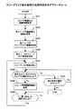
次に図6について説明する。図6はスコープライフ表示処理の処理内容を示すフローチャートである。この処理は、DBサーバ40にスコープ情報41が格納されているスコープ10の各々についてのスコープライフを求め、PC30の表示部66にスコープライフの表示を行う処理である。
【0041】
ここでスコープライフについて説明する。スコープ10のスコープライフとは、スコープ10に対しメンテナンスの実施が推奨される経年変化量に対するスコープ10の使用開始(若しくは直近のメンテナンス後)から現在までの経年変化量の割合を示すものである。本実施形態においては、使用時間や使用回数といったスコープ10の使用履歴に関する情報に基づいてスコープ10についての使用開始から現在までの経年変化量の推測を行ない、スコープ10について予め設定されている経年変化の程度、すなわちスコープ10に対しメンテナンスの実施が推奨される経年変化量に対するこの推測結果の割合をPC30の表示部66で描画により視覚的に表示するようにしてスコープライフをユーザに提示する。
【0042】
図6に示されている処理は、PC30のCPU61によって行われる処理であり、このCPU61は、PC30の記憶部64に格納されている制御プログラムを実行することによってこの処理を実現する。また、この処理は、スコープ履歴の表示をPC30の表示部66に行わせる指示を示す入力がPC30の入力部65に対して行われたことをPC30のCPU61が検出することによって開始される。
【0043】
まず、S201では、DBサーバ40へ指示を与えてDBサーバ40の記憶部64に格納されている全てのスコープ情報41及び対応する履歴情報42をPC30へ送付させる処理が行われる。DBサーバ40ではこの指示に応じ、記憶部64から読み出したスコープ情報41及び履歴情報42をPC30へ送付する。
【0044】
S202では、PC30の記憶部64に予め格納されている各スコープの経年変化係数のうち、前ステップの処理によって取得したスコープ情報41に対応するスコープ10と同一機種についてのものを全て読み出す処理が行われる。
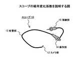
ここで、スコープについての使用開始から現在までの経年変化の推測の手法、及びスコープの経年変化係数について説明する。本実施形態では、図7に示すスコープ10の経年変化量Nを下記の式により算出する。
【0045】
N=P1(α+β+γ+Δ)+P2(ε+ζ+η+θ)+C
上式において、P1は使用開始から現在までの総使用時間、P2は使用開始から現在までの総使用回数であり、これらはプローブ10についてのプローブ情報41に示されている。また、α、β、γ、及びΔは単位使用回数当たりの故障の発生数を示す経年変化係数、ε、ζ、η、及びθは単位使用回数当たりの故障の発生数を示す経年変化係数であり、α及びεはカメラ部12についてのもの、β及びζは蛇管部13についてのもの、γ及びηは操作部14についてのもの、そしてΔ及びθは接続部15についてのものである。また、Cは定数である経年変化係数である。なお、これらの経年変化係数は例えば同一機種のプローブについての故障の故障の発生数により統計的に算出する。
【0046】
なお、スコープ10の経年変化量の算出は上述したもの以外の手法を採用してもよい。
図6の説明へ戻る。S203では、各スコープについてのスコープライフ閾値を取得する処理が行なわれ、続くS204では各スコープのスコープライフ表示を決定する処理が行われ、S205においてスコープリスト画面をPC30の表示部66に表示させる処理が行われる。
【0047】
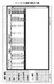
ここで図8について説明する。同図はスコープリスト画面の一例を示している。このスコープリスト画面は、DBサーバ40の記憶部64に格納されている全てのスコープ情報41及び履歴情報42の一部と各スコープについてのスコープライフ表示とを一覧表示するものである。
【0048】
図8を参照すると、DBサーバ40の記憶部64には8つのスコープについてのスコープ情報41が格納されていることが分かり、各スコープについて、スコープ情報41である「スコープ名」(すなわち「スコープ機種名」)、「スコープID」、「使用開始日」、「使用回数」、及び「使用時間」の各データの内容と、履歴情報42である「洗浄有無」のデータの内容とが表示されていることが分かる。なお、このスコープリスト画面において、「スコープNo」は各スコープについての情報をスコープリスト画面に表示する際に便宜上降順に付した番号である。また、「分類」はスコープの種類の分類を示しており、この情報は、例えばDBサーバ40の記憶部64に格納されているスコープの機種名とスコープの種類の分類との対応を示す不図示のテーブルを参照することによって取得する。
【0049】
この図8に示したスコープリスト画面における各行の右端には、その行で示されているスコープについてのスコープライフの表示がなされている。本実施形態においては、スコープライフは横一行に並べられた4つの丸印で示される。
この丸印は、スコープが未使用であるときにはその4つ全てが白丸で表示される。その後、そのスコープの経年変化量の値が大きくなるにつれて、まず、その左端の丸印のみが白丸→網掛け丸→黒丸の順に変化し、左端の丸印が黒丸となった次にはその黒丸の表示を維持しつつその左端から二番目の丸印が白丸→網掛け丸→黒丸の順に変化する。その後、スコープの経年変化量の値の増加に応じてその左端から三番目及び四番目の丸印についても同様に変化し、メンテナンスの実施が推奨される経年変化量に達したときには4つの丸印全てが黒丸となる。つまり、このスコープライフの表示では、[白、白、白、白]の表示から[黒、黒、黒、黒]の表示まで、全部で9段階の表示が行われる。
【0050】
S203の処理によって取得されるスコープライフ閾値とは、前記した式によって算出されたスコープの経年変化量の値に対応するスコープライフの表示を決定するための閾値である。本実施形態においては9段階のスコープライフ表示を行うので、スコープライフ閾値はスコープの機種毎に8つの数値が予め用意されており、例えばPC30の記憶部64に予め格納されている。S204のスコープライフ表示の決定処理では、スコープの経年変化量の値が各スコープライフ閾値と大小比較され、その比較結果に基づいて9段階のスコープライフ表示のうちのいずれの表示を行うかが決定される。本実施形態ではこの決定に基づいたスコープライフの表示をスコープリスト画面において行う。
【0051】
図6のフローチャートの説明へ戻る。S206では、前述したS205の処理よってPC30の表示部66に表示されているスコープリスト画面から、特定のスコープの選択を確定する指示がPC30の入力部65に対してなされたか否かが判定され、この判定結果がYesならばS208に処理が進む。一方、この判定結果がNoならばS207において、スコープの選択を除いた他の指示が入力部65に対してなされたか否かが判定され、この判定結果がYesならばこのスコープライフ表示処理を終了し、その指示に応じて行われる他の処理の実行を開始する。一方、S207の判定処理の結果がNoならばS206へ処理が戻って上述した処理が繰り返される。
【0052】
S208では、スコープ使用履歴画面をPC30の表示部66に表示させる処理が行われる。
ここで図9について説明する。同図はスコープ使用履歴画面の一例を示している。このスコープ使用履歴画面は、S206の処理において検出された指示に係るスコープについてのスコープ情報41とスコープライフ表示とを画面の左端に示すと共に、このスコープのについての履歴情報42、すなわち、「使用日」、「使用開始時刻」、「使用者」、「患者ID」、「患者名」、「検査項目」、及び「洗浄有無」の各種データを示すものである。
【0053】
S209では、図9のスコープ使用履歴画面の左下端に設けられている「一覧に戻る」の表示を選択する指示がPC30の入力部65に対してなされたか否かが判定され、この判定結果がYesならばS205へ処理が戻って上述した処理が繰り返される。一方、この判定結果がNoならば、判定結果がYesとなるまでこのS209の処理が繰り返される。
【0054】
以上までの処理がスコープライフ表示処理である。
このように、PC30のCPU61によって上述したスコープ情報取得・更新処理及びスコープライフ表示処理が行われることにより、使用履歴に関する情報に基づいたスコープについての使用開始から現在までの経年変化の推測、及びそのスコープについて予め設定されているメンテナンスの実施が推奨される経年変化の程度に対するこの推測の結果の割合の表示が実現される。
【0055】
なお、上述した実施形態におけるスコープライフ表示は、丸印を白丸→網掛け丸→黒丸の順に変化させるようにしていたが、その代わりに丸印の色彩を変化させる、あるいはスコープライフ表示として用いる図形の面積や形状を変化させる、等の表示手法を採用することもできる。また、描画によるアナログ的な表示を行う代わりに、メンテナンスの実施が推奨される経年変化の程度に対するこの推測の結果の割合を例えば%表示で数値表示を行うといったデジタル的な表示を行うようにしてもよい。
【0056】
ところで、以上までに説明したスコープ情報取得・更新処理やスコープライフ表示処理をコンピュータに行なわせるプログラムを作成してコンピュータで読み取り可能な記録媒体に記録させておき、そのプログラムを記録媒体からコンピュータに読み込ませてCPUで実行させるようにしても本発明は実施できる。
【0057】
記録させた制御プログラムをコンピュータで読み取ることの可能な記録媒体の例を図10に示す。このような記録媒体としては、例えば、コンピュータ81に内蔵若しくは外付けの付属装置として備えられるROMやハードディスク装置などの記憶装置82、FD(フレキシブル・ディスク)、MO(光磁気ディスク)、CD−ROM、DVD−ROMなどといった携帯可能記録媒体83等が利用できる。
【0058】
また、記録媒体としては、コンピュータ81と通信ネットワーク84を介して接続されているプログラムサーバ85に内蔵若しくは外付けされる記憶装置86であってもよく、このような場合には、プログラムサーバ85側の記憶装置86に記録されている制御プログラムで搬送信号を変調して得られる伝送信号をプログラムサーバ85側から送信させ、コンピュータ81側では通信ネットワーク84を介して受信されるこの伝送信号から制御プログラムを復調してCPUに実行させればよい。
【0059】
その他、本発明は、上述した実施形態に限定されることなく、種々の改良・変更が可能である。
例えば、本実施形態においては、スコープ履歴の表示をPC30の表示部66に行わせる指示を示す入力がPC30の入力部65に対して行われたときにPC30のCPU61がスコープライフ表示処理を行うようにしていたが、その代わりに、スコープ10が内視鏡システム20に装着されたこと若しくはスコープ10が内視鏡システム20から取り外されたことがPC30のCPU61によって検出されたときにスコープライフ表示処理を行うようにしてもよく、こうすることにより、装着/取り外しが行われたスコープ10についてのスコープライフ表示を直ちにその使用者に提示することができるので有益である。また、このときには、図8に示したスコープリスト画面の表示を行う前に、そのスコープ10についての図9に示したスコープ使用履歴画面を直ちに表示するようにすると、スコープ情報41とスコープライフ表示と共にそのスコープ10についての履歴情報42の詳細をその使用者に提示することができ、便利である。
【0060】
【発明の効果】
以上詳細に説明したように、本発明は、内視鏡の使用履歴に関する情報を取得し、該情報に基づいて該内視鏡についての使用開始から現在までの経年変化の推測を行ない、該内視鏡について予め設定されている経年変化の程度に対する該推測の結果の割合を表示する。
【0061】
こうすることにより、単調に変化していく内視鏡についての使用開始から現在までの経年変化の推測の結果が、その内視鏡についての経年変化の程度に対する割合によって提示されるので、内視鏡の経年変化が所定の程度となるまでに残されている余裕を内視鏡のユーザに適切に提供することができるという効果を奏する。
【図面の簡単な説明】
【図1】本発明の原理構成を示す図である。
【図2】本発明を実施するシステムの構成を示す図である。
【図3】図2のPC及びDBサーバの構成を示す図である。
【図4】各種データのデータ構造を示す図である。
【図5】スコープ情報取得・更新処理の処理内容を示すフローチャートである。
【図6】スコープライフ表示処理の処理内容を示すフローチャートである。
【図7】スコープの経年変化を説明する図である。
【図8】スコープリスト画面の例を示す図である。
【図9】スコープ使用履歴画面の例を示す図である。
【図10】記録させた制御プログラムをコンピュータで読み取ることの可能な記録媒体の例を示す図である。
【符号の説明】
1 履歴情報表示手段
2 推測手段
3 表示手段
10 スコープ
11 EEPROM
12 カメラ部
13 蛇管部
14 操作部
15 接続部
20 内視鏡システム
30 PC
40 DBサーバ
41 スコープ情報
42 履歴情報
50 院内LAN
61 CPU
62 ROM
63 RAM
64 記憶部
65 入力部
66 表示部
67 出力部
68 LANインタフェース
69 内視鏡システムインタフェース
70 バス
81 コンピュータ
82、86 記憶装置
83 携帯可能記録媒体
84 通信ネットワーク
85 プログラムサーバ[0001]
TECHNICAL FIELD OF THE INVENTION
The present invention relates to a technique for supporting business operations of an endoscope inspection performed in a medical institution or the like, and particularly to a technique for managing use of an endoscope scope.
[0002]
[Prior art]
2. Description of the Related Art As a technique for performing business support of an endoscope inspection, techniques disclosed in Patent Literature 1 and
[0003]
[Patent Document 1]
JP 2001-46326 A
[Patent Document 2]
JP-A-2002-73615
[0004]
[Problems to be solved by the invention]
In the display of the date and time of the recommended maintenance time of the endoscope disclosed in Patent Literature 1, when the usage frequency of the endoscope changes significantly, the display of the date and time changes every moment. Since the display of this date can change both before and after, especially if the display of this date suddenly changes to an earlier time, the maintenance It is possible to miss. Therefore, a failure may occur during the execution of the inspection, and the endoscope may need to be replaced. As a result, the time required for the inspection may be prolonged.
[0005]
In view of the above problems, it is an object of the present invention to appropriately provide a user of an endoscope with a margin left before the aging of the endoscope becomes a predetermined degree.
[0006]
[Means for Solving the Problems]
First, FIG. 1 will be described. FIG. 1 is a principle configuration diagram of an endoscope information system according to the present invention.
The history information obtaining means 1 obtains information on the usage history of the endoscope.
[0007]
The estimating means 2 estimates the secular change from the start of use of the endoscope to the present based on this information.
The
[0008]
Here, the degree of aging set in advance for the endoscope may be set to an extent that maintenance is recommended for the endoscope.
According to the above configuration, the result of estimating the secular change from the start of use for the endoscope that changes monotonically to the present is presented by the ratio to the degree of secular change for the endoscope. It is possible to appropriately provide the user of the endoscope with a margin left before the aging of the endoscope becomes a predetermined degree.
[0009]
In the endoscope information system according to the present invention described above, the information on the use history acquired by the history information acquisition unit 1 indicates at least one or both of the use time and the number of times of use of the endoscope. Can be.
[0010]
According to this configuration, the estimating means 2 estimates the secular change from the start of use of the endoscope to the present based on one or both of the use time and the number of times of use of the endoscope. Can be.
In the endoscope information system according to the present invention described above, the information on the usage history acquired by the history information acquiring means 1 may be stored in the scope storage means provided in the endoscope. .
[0011]
According to this configuration, it is easy to manage the correspondence between the endoscope and the information on the usage history of the endoscope.
Here, the scope storage unit further stores scope identification information for identifying the endoscope, and the endoscope information system stores information on the usage history of each of the plurality of endoscopes in the scope. It may be configured to further include a use history storage unit that is stored in association with the identification information.
[0012]
According to this configuration, even if the endoscope is detached from the endoscope information system, the endoscope has a margin left before the aging of the endoscope becomes a predetermined degree. Of users.
Further, in the endoscope information system according to the present invention described above, the
[0013]
According to this configuration, the margin left until the aging of the endoscope becomes a predetermined degree is presented in an analog manner by drawing, so that it is possible to quickly grasp how much the margin is left. be able to.
Further, in the endoscope information system according to the present invention described above, the display means 3 may be configured to individually display the ratios of the results of the above estimations for a plurality of endoscopes for each endoscope. it can.
[0014]
According to this configuration, the user of the endoscope can quickly recognize the ratio of the result of the above-described estimation with respect to the specific endoscope.
Further, in the endoscope information system according to the present invention described above, the display means 3 may be configured to display a list of the ratio of the result of the estimation described above for each of the plurality of endoscopes.
[0015]
According to this configuration, the user of the endoscope can collectively recognize the ratio of the result of the above-mentioned estimation for a plurality of endoscopes.
In addition, a storage means for storing information relating to the use history of the endoscope is provided. The estimation of the aging is performed based on the information, and the ratio of the result of the estimation to the degree of the aging set in advance for the endoscope is displayed, that is, the endoscope according to the present invention described above. An endoscope to which the endoscope information system displays a ratio of a result of the above estimation to a preset degree of aging is also related to the present invention.
[0016]
Note that even a program that causes a computer to execute processing corresponding to the functions performed by the components of the endoscope information system according to the present invention described above, the program is read and executed by the computer. Since the same operation and effects as those of the endoscope information system are achieved, the above-described problem is solved.
[0017]
BEST MODE FOR CARRYING OUT THE INVENTION
Hereinafter, embodiments of the present invention will be described with reference to the drawings.
FIG. 2 shows the configuration of a system for implementing the present invention. This system is assumed to be installed in a hospital.
[0018]
The
The
[0019]
The
A DB (database)
[0020]
Next, FIG. 3 will be described. This figure shows the configuration of the
3 includes a
[0021]
A CPU (Central Processing Unit) 61 is a central processing unit that controls the operation of the entire apparatus shown in FIG.
A ROM (Read Only Memory) 62 is a memory in which a basic control program to be executed by the
[0022]
A RAM (Random Access Memory) 63 is a memory that is used as a work memory when the
[0023]
The
[0024]
The
[0025]
The
The
[0026]
The
The
[0027]
It should be noted that the apparatus shown in FIG. 3 is normally provided as long as it is a computer system having a standard hardware configuration, and it is possible to configure the
Next, FIG. 4 will be described. 2 shows the data structures of various data handled in the system shown in FIG. 2, wherein (a) shows the data structure of the scope information, and (b) shows the data structure of the history information. I have.
[0028]
The
[0029]
The
[0030]
The
[0031]
Note that the
Next, FIG. 5 will be described. FIG. 11 is a flowchart showing the contents of the scope information acquisition / update processing. In this process, when the
[0032]
The process shown in FIG. 5 is a process performed by the
[0033]
First, in S101, a process of giving an instruction to the
In S102, a process of giving an instruction to the
[0034]
In S103, the contents of the response from the
[0035]
In S105, the
[0036]
In S106, a process of resetting and starting a timer for measuring the passage of time, which is established by the execution of the control program by the
Thereafter, in S107, the determination process of S107 is repeated until the
[0037]
In S108, a process of stopping the timing operation of the timer started by the process of S106 described above is performed.
In S109, the time measured by the timer stopped in the process of the previous step, that is, the current use time of the
[0038]
In S110, a process of incrementing (adding 1 to) the value indicated by the data of the "number of uses" in the
In S111, the data of the “use time” and the “use count” updated by the processing of S109 and S110 described above are sent to the
[0039]
In S112, the data of the “use time” and the “use count” updated by the processing of S109 and S110 described above are sent to the
[0040]
The above processing is the scope information acquisition / update processing.
Next, FIG. 6 will be described. FIG. 6 is a flowchart showing the processing contents of the scope life display processing. This process is a process of obtaining a scope life for each of the
[0041]
Here, the scope life will be described. The scope life of the
[0042]
The process illustrated in FIG. 6 is a process performed by the
[0043]
First, in S201, a process of giving an instruction to the
[0044]
In S202, the process of reading out all the aging coefficients of each scope stored in advance in the
Here, a method of estimating the aging of the scope from the start of use to the present and the aging coefficient of the scope will be described. In the present embodiment, the aging amount N of the
[0045]
N = P1 (α + β + γ + Δ) + P2 (ε + ζ + η + θ) + C
In the above equation, P1 is the total use time from the start of use to the present, P2 is the total number of uses from the start of use to the present, and these are shown in the
[0046]
In addition, the calculation of the aging amount of the
Returning to the description of FIG. In S203, a process of acquiring a scope life threshold value for each scope is performed. In subsequent S204, a process of determining a scope life display of each scope is performed, and in S205, a scope list screen is displayed on the
[0047]
FIG. 8 will now be described. This figure shows an example of the scope list screen. The scope list screen displays a list of all the
[0048]
Referring to FIG. 8, it can be seen that the
[0049]
At the right end of each line in the scope list screen shown in FIG. 8, the scope life of the scope shown in the line is displayed. In the present embodiment, the scope life is indicated by four circles arranged in one horizontal line.
When the scope is unused, all four circles are displayed as white circles. After that, as the value of the aging amount of the scope increases, first, only the leftmost circle changes in the order of white circle → shaded circle → black circle, the leftmost circle becomes a black circle, and then the black circle , The second circle from the left end changes in the order of white circle → shaded circle → black circle. Thereafter, the third and fourth circles from the left end also change in accordance with the increase in the aging value of the scope, and when the aging amount at which maintenance is recommended is reached, four circles are displayed. All become black circles. That is, in the display of the scope life, a total of nine levels of display are performed from the display of [white, white, white, white] to the display of [black, black, black, black].
[0050]
The scope life threshold value acquired by the process of S203 is a threshold value for determining display of the scope life corresponding to the value of the aging amount of the scope calculated by the above-described formula. In the present embodiment, nine stages of scope life display are performed, so that eight values of scope life threshold are prepared in advance for each scope model, and are stored in the
[0051]
Returning to the description of the flowchart of FIG. In S206, it is determined whether or not an instruction to determine the selection of a specific scope has been given to the
[0052]
In S208, a process of displaying the scope use history screen on the
Here, FIG. 9 will be described. This figure shows an example of the scope use history screen. This scope use history screen shows, at the left end of the screen, the
[0053]
In S209, it is determined whether or not an instruction to select the display of “return to list” provided at the lower left end of the scope use history screen of FIG. 9 has been made to the
[0054]
The above processing is the scope life display processing.
As described above, the scope information obtaining / updating process and the scope life displaying process are performed by the
[0055]
In the scope life display in the above-described embodiment, the circles are changed in the order of white circles → shaded circles → black circles. Instead, the colors of the circles are changed or graphics used as the scope life display are changed. A display method such as changing the area or shape of the image may be adopted. In addition, instead of performing analog display by drawing, digital display such as numerical display of the ratio of the result of this estimation to the degree of aging that is recommended to perform maintenance, for example, in% display is performed. Is also good.
[0056]
By the way, a program for causing a computer to perform the scope information acquisition / update processing and the scope life display processing described above is created and recorded on a computer-readable recording medium, and the program is read from the recording medium to the computer. The present invention can also be implemented by causing the CPU to execute the program.
[0057]
FIG. 10 shows an example of a recording medium in which the recorded control program can be read by a computer. As such a recording medium, for example, a
[0058]
Further, the recording medium may be a
[0059]
In addition, the present invention is not limited to the embodiments described above, and various modifications and changes are possible.
For example, in the present embodiment, the
[0060]
【The invention's effect】
As described in detail above, the present invention obtains information on the use history of the endoscope, estimates the secular change from the start of use of the endoscope to the present based on the information, The ratio of the result of the estimation to the degree of aging set in advance for the endoscope is displayed.
[0061]
By doing so, the result of estimating the secular change from the start of use of the endoscope which is monotonically changing to the present is presented by the ratio to the degree of secular change of the endoscope. The effect of being able to appropriately provide the user of the endoscope with a margin left until the aging of the mirror becomes a predetermined degree is obtained.
[Brief description of the drawings]
FIG. 1 is a diagram showing the principle configuration of the present invention.
FIG. 2 is a diagram illustrating a configuration of a system that implements the present invention.
FIG. 3 is a diagram illustrating a configuration of a PC and a DB server in FIG. 2;
FIG. 4 is a diagram showing a data structure of various data.
FIG. 5 is a flowchart showing processing contents of scope information acquisition / update processing.
FIG. 6 is a flowchart showing processing contents of scope life display processing.
FIG. 7 is a diagram illustrating a secular change of a scope.
FIG. 8 is a diagram showing an example of a scope list screen.
FIG. 9 is a diagram illustrating an example of a scope use history screen.
FIG. 10 is a diagram illustrating an example of a recording medium on which a recorded control program can be read by a computer.
[Explanation of symbols]
1 History information display means
2 Guessing means
3 Display means
10 Scope
11 EEPROM
12 Camera section
13 Serpentine tube
14 Operation unit
15 Connection
20 Endoscope system
30 PC
40 DB server
41 Scope information
42 History information
50 Hospital LAN
61 CPU
62 ROM
63 RAM
64 storage unit
65 Input section
66 Display
67 Output section
68 LAN interface
69 Endoscope system interface
70 bus
81 Computer
82, 86 storage device
83 Portable recording media
84 Communication Network
85 Program Server
Claims (10)
Translated fromJapanese前記情報に基づいて前記内視鏡についての使用開始から現在までの経年変化の推測を行う推測手段と、
前記内視鏡について予め設定されている経年変化の程度に対する前記推測の結果の割合を表示する表示手段と、
を有することを特徴とする内視鏡情報システム。History information acquisition means for acquiring information on the use history of the endoscope,
Estimating means for estimating the secular change from the start of use of the endoscope to the present based on the information,
Display means for displaying the ratio of the result of the estimation to the degree of aging set in advance for the endoscope,
An endoscope information system comprising:
前記内視鏡情報システムは、複数の内視鏡の各々についての使用履歴に関する情報がスコープ識別情報に関連付けられて記憶される使用履歴記憶手段を更に有する、
ことを特徴とする請求項4に記載の内視鏡情報システム。In the scope storage means, scope identification information for identifying the endoscope is further stored,
The endoscope information system further includes a usage history storage unit in which information regarding a usage history for each of the plurality of endoscopes is stored in association with the scope identification information.
The endoscope information system according to claim 4, wherein:
前記記憶手段に記憶されている情報を取得する内視鏡情報システムによって、前記内視鏡についての使用開始から現在までの経年変化の推測が該情報に基づいて行なわれ、該内視鏡について予め設定されている経年変化の程度に対する該推測の結果の割合が表示される、
ことを特徴とする内視鏡。Own storage means for storing information on the use history of the endoscope,
The endoscope information system for acquiring the information stored in the storage means estimates the secular change from the start of use of the endoscope to the present based on the information. The ratio of the result of the estimation to the set degree of aging is displayed.
An endoscope characterized in that:
前記情報に基づいて前記内視鏡についての使用開始から現在までの経年変化の推測を行う推測処理と、
前記内視鏡について予め設定されている経年変化の程度に対する前記推測の結果の割合を表示する表示処理と、
をコンピュータに行わせるためのプログラム。History information acquisition processing for acquiring information on the use history of the endoscope;
An estimation process for estimating the secular change from the start of use of the endoscope to the present based on the information,
A display process of displaying a ratio of the result of the estimation to the degree of aging set in advance for the endoscope,
To make a computer do the work.
Priority Applications (5)
| Application Number | Priority Date | Filing Date | Title |
|---|---|---|---|
| JP2002344900AJP2004174008A (en) | 2002-11-28 | 2002-11-28 | Endoscope information system, endoscope and program |
| US10/693,432US7670283B2 (en) | 2002-11-28 | 2003-10-24 | Endoscope information system |
| EP03024598AEP1424036B1 (en) | 2002-11-28 | 2003-10-28 | System and method for managing information for an endoscope |
| DE60306309TDE60306309T2 (en) | 2002-11-28 | 2003-10-28 | System and method for managing information of an endoscope |
| AT03024598TATE330533T1 (en) | 2002-11-28 | 2003-10-28 | SYSTEM AND METHOD FOR MANAGING INFORMATION OF AN ENDOSCOPE |
Applications Claiming Priority (1)
| Application Number | Priority Date | Filing Date | Title |
|---|---|---|---|
| JP2002344900AJP2004174008A (en) | 2002-11-28 | 2002-11-28 | Endoscope information system, endoscope and program |
Publications (1)
| Publication Number | Publication Date |
|---|---|
| JP2004174008Atrue JP2004174008A (en) | 2004-06-24 |
Family
ID=32290462
Family Applications (1)
| Application Number | Title | Priority Date | Filing Date |
|---|---|---|---|
| JP2002344900APendingJP2004174008A (en) | 2002-11-28 | 2002-11-28 | Endoscope information system, endoscope and program |
Country Status (5)
| Country | Link |
|---|---|
| US (1) | US7670283B2 (en) |
| EP (1) | EP1424036B1 (en) |
| JP (1) | JP2004174008A (en) |
| AT (1) | ATE330533T1 (en) |
| DE (1) | DE60306309T2 (en) |
Cited By (25)
| Publication number | Priority date | Publication date | Assignee | Title |
|---|---|---|---|---|
| JP2006141671A (en)* | 2004-11-19 | 2006-06-08 | Pentax Corp | Electronic endoscope and endoscope apparatus |
| JP2006230491A (en)* | 2005-02-22 | 2006-09-07 | Olympus Medical Systems Corp | Endoscope cleaning and disinfection device |
| JP2008086777A (en)* | 2006-10-03 | 2008-04-17 | Karl Storz Imaging Inc | Universal scope reader |
| JP2013009908A (en)* | 2011-06-30 | 2013-01-17 | Hoya Corp | Endoscope apparatus |
| US8599250B2 (en) | 2002-03-12 | 2013-12-03 | Karl Storz Imaging, Inc. | Wireless camera coupling |
| JP2014004156A (en)* | 2012-06-25 | 2014-01-16 | Hoya Corp | External module for endoscope, and endoscope system |
| US8723936B2 (en) | 2002-03-12 | 2014-05-13 | Karl Storz Imaging, Inc. | Wireless camera coupling with rotatable coupling |
| US9238099B2 (en) | 2004-11-24 | 2016-01-19 | Bayer Healthcare Llc | System and apparatus for modeling pressures generated during an injection procedure |
| CN105263388A (en)* | 2014-03-11 | 2016-01-20 | 奥林巴斯株式会社 | Endoscopic Leak Inspection Device |
| US9510740B2 (en) | 2002-03-12 | 2016-12-06 | Karl Storz Endovision, Inc. | Auto recognition of a shaver blade for medical use |
| JPWO2016017493A1 (en)* | 2014-07-28 | 2017-04-27 | オリンパス株式会社 | Endoscope system and image processing apparatus |
| US9949704B2 (en) | 2012-05-14 | 2018-04-24 | Bayer Healthcare Llc | Systems and methods for determination of pharmaceutical fluid injection protocols based on x-ray tube voltage |
| US9959389B2 (en) | 2010-06-24 | 2018-05-01 | Bayer Healthcare Llc | Modeling of pharmaceutical propagation and parameter generation for injection protocols |
| US10463782B2 (en) | 2006-12-29 | 2019-11-05 | Bayer Healthcare Llc | Patient-based parameter generation systems for medical injection procedures |
| US10898638B2 (en) | 2016-03-03 | 2021-01-26 | Bayer Healthcare Llc | System and method for improved fluid delivery in multi-fluid injector systems |
| US11141535B2 (en) | 2017-08-31 | 2021-10-12 | Bayer Healthcare Llc | Fluid path impedance assessment for improving fluid delivery performance |
| US11278853B2 (en) | 2013-03-13 | 2022-03-22 | Bayer Healthcare Llc | Method for controlling fluid accuracy and backflow compensation |
| US11478581B2 (en) | 2017-08-31 | 2022-10-25 | Bayer Healthcare Llc | Fluid injector system volume compensation system and method |
| US11598664B2 (en) | 2017-08-31 | 2023-03-07 | Bayer Healthcare Llc | Injector pressure calibration system and method |
| US11779702B2 (en) | 2017-08-31 | 2023-10-10 | Bayer Healthcare Llc | Method for dynamic pressure control in a fluid injector system |
| US11786652B2 (en) | 2017-08-31 | 2023-10-17 | Bayer Healthcare Llc | System and method for drive member position and fluid injector system mechanical calibration |
| US12208239B2 (en) | 2018-08-28 | 2025-01-28 | Bayer Healthcare Llc | Fluid injector system, method of preventing fluid backflow, and computer program product |
| US12251544B2 (en) | 2018-04-19 | 2025-03-18 | Bayer Healthcare Llc | System and method for air detection in fluid injector |
| US12263326B2 (en) | 2016-11-14 | 2025-04-01 | Bayer Healthcare Llc | Methods and systems for verifying the contents of a syringe used for medical fluid delivery |
| US12427249B2 (en) | 2018-08-28 | 2025-09-30 | Bayer Healthcare Llc | Fluid injector system with improved ratio performance |
Families Citing this family (17)
| Publication number | Priority date | Publication date | Assignee | Title |
|---|---|---|---|---|
| US6515273B2 (en)* | 1999-08-26 | 2003-02-04 | Masimo Corporation | System for indicating the expiration of the useful operating life of a pulse oximetry sensor |
| JP2006218233A (en)* | 2005-02-14 | 2006-08-24 | Olympus Corp | Endoscope apparatus |
| US10188348B2 (en) | 2006-06-05 | 2019-01-29 | Masimo Corporation | Parameter upgrade system |
| US20080016120A1 (en)* | 2006-06-29 | 2008-01-17 | Yosi Markovich | System and method for case management |
| US7880626B2 (en)* | 2006-10-12 | 2011-02-01 | Masimo Corporation | System and method for monitoring the life of a physiological sensor |
| EP2116171A4 (en)* | 2007-02-26 | 2013-04-03 | Olympus Medical Systems Corp | Capsule endoscope system |
| JP5026886B2 (en)* | 2007-08-10 | 2012-09-19 | オリンパスメディカルシステムズ株式会社 | Medical device and medical system provided with the medical device |
| JP5100303B2 (en)* | 2007-10-17 | 2012-12-19 | 富士フイルム株式会社 | Endoscope information management system, cleaning information management system, and cleaning information management device |
| US8571619B2 (en) | 2009-05-20 | 2013-10-29 | Masimo Corporation | Hemoglobin display and patient treatment |
| DE102014109888B4 (en) | 2014-07-15 | 2022-12-01 | Karl Storz Se & Co. Kg | Method and device for testing the light and/or image transmission properties of an endoscopic or exoscopic system |
| US10440246B2 (en)* | 2014-11-19 | 2019-10-08 | Kiran K. Bhat | System for enabling remote annotation of media data captured using endoscopic instruments and the creation of targeted digital advertising in a documentation environment using diagnosis and procedure code entries |
| EP3252702A4 (en)* | 2015-01-28 | 2018-10-24 | Olympus Corporation | Examination work support system |
| WO2017094363A1 (en)* | 2015-11-30 | 2017-06-08 | オリンパス株式会社 | Centralized control apparatus |
| DE102017128744A1 (en) | 2017-12-04 | 2019-06-06 | Karl Storz Se & Co. Kg | endoscope |
| DE102019120281A1 (en)* | 2019-07-26 | 2021-01-28 | Olympus Winter & Ibe Gmbh | Medical system and method for determining a maintenance requirement of a light guide component of the medical system |
| DE102021126617A1 (en)* | 2021-10-13 | 2023-04-13 | Olympus Winter & Ibe Gmbh | Delivery system for endoscopes |
| DE102022103586A1 (en)* | 2022-02-15 | 2023-08-17 | Olympus Winter & Ibe Gmbh | Procedure for handling medical device status information, and system |
Citations (5)
| Publication number | Priority date | Publication date | Assignee | Title |
|---|---|---|---|---|
| JPH07171089A (en)* | 1993-10-27 | 1995-07-11 | Asahi Optical Co Ltd | Endoscope device |
| JPH07171090A (en)* | 1993-11-05 | 1995-07-11 | Asahi Optical Co Ltd | Endoscope device |
| JP2000126124A (en)* | 1998-10-23 | 2000-05-09 | Olympus Optical Co Ltd | Life meter |
| JP2001046326A (en)* | 1999-05-31 | 2001-02-20 | Olympus Optical Co Ltd | Data filing system for endoscope |
| JP2002183547A (en)* | 2000-12-11 | 2002-06-28 | Hitachi Ltd | How to trade reused parts |
Family Cites Families (11)
| Publication number | Priority date | Publication date | Assignee | Title |
|---|---|---|---|---|
| US4539632A (en)* | 1982-09-28 | 1985-09-03 | Borg-Warner Corporation | Programmable maintenance timer system |
| US4876632A (en)* | 1988-02-10 | 1989-10-24 | Tekna, Inc. | Flashlight with battery life indicator module |
| JPH034831A (en)* | 1989-06-01 | 1991-01-10 | Toshiba Corp | endoscope equipment |
| US5830121A (en)* | 1993-10-27 | 1998-11-03 | Asahi Kogaku Kogyo Kabushiki Kaisha | Endoscopic apparatus having an endoscope and a peripheral device wherein total usage of the endoscope is quantified and recorded |
| AU697140B3 (en) | 1998-06-18 | 1998-09-24 | Peter Osborne | Surgical instrument management system |
| US6322496B1 (en)* | 1998-11-06 | 2001-11-27 | Asahi Kogaku Kogyo Kabushiki Kaisha | Electronic endoscope system |
| JP3556508B2 (en)* | 1999-03-15 | 2004-08-18 | オリンパス株式会社 | Lamp life meter and endoscope light source device |
| JP3791894B2 (en) | 2000-05-12 | 2006-06-28 | オリンパス株式会社 | Endoscopic image filing system |
| JP3864035B2 (en) | 2000-05-19 | 2006-12-27 | オリンパス株式会社 | Endoscope system |
| JP3742549B2 (en) | 2000-08-29 | 2006-02-08 | オリンパス株式会社 | Medical image filing system |
| JP2003068478A (en)* | 2001-08-23 | 2003-03-07 | Olympus Optical Co Ltd | Light source device |
- 2002
- 2002-11-28JPJP2002344900Apatent/JP2004174008A/enactivePending
- 2003
- 2003-10-24USUS10/693,432patent/US7670283B2/enactiveActive
- 2003-10-28ATAT03024598Tpatent/ATE330533T1/ennot_activeIP Right Cessation
- 2003-10-28DEDE60306309Tpatent/DE60306309T2/ennot_activeExpired - Lifetime
- 2003-10-28EPEP03024598Apatent/EP1424036B1/ennot_activeExpired - Lifetime
Patent Citations (5)
| Publication number | Priority date | Publication date | Assignee | Title |
|---|---|---|---|---|
| JPH07171089A (en)* | 1993-10-27 | 1995-07-11 | Asahi Optical Co Ltd | Endoscope device |
| JPH07171090A (en)* | 1993-11-05 | 1995-07-11 | Asahi Optical Co Ltd | Endoscope device |
| JP2000126124A (en)* | 1998-10-23 | 2000-05-09 | Olympus Optical Co Ltd | Life meter |
| JP2001046326A (en)* | 1999-05-31 | 2001-02-20 | Olympus Optical Co Ltd | Data filing system for endoscope |
| JP2002183547A (en)* | 2000-12-11 | 2002-06-28 | Hitachi Ltd | How to trade reused parts |
Cited By (35)
| Publication number | Priority date | Publication date | Assignee | Title |
|---|---|---|---|---|
| US8194122B2 (en) | 2002-03-12 | 2012-06-05 | Karl Storz Imaging, Inc. | Universal scope reader |
| US8599250B2 (en) | 2002-03-12 | 2013-12-03 | Karl Storz Imaging, Inc. | Wireless camera coupling |
| US8723936B2 (en) | 2002-03-12 | 2014-05-13 | Karl Storz Imaging, Inc. | Wireless camera coupling with rotatable coupling |
| US9271630B2 (en) | 2002-03-12 | 2016-03-01 | Karl Storz Imaging, Inc. | Wireless camera coupling with rotatable coupling |
| US9510740B2 (en) | 2002-03-12 | 2016-12-06 | Karl Storz Endovision, Inc. | Auto recognition of a shaver blade for medical use |
| JP2006141671A (en)* | 2004-11-19 | 2006-06-08 | Pentax Corp | Electronic endoscope and endoscope apparatus |
| US9950107B2 (en) | 2004-11-24 | 2018-04-24 | Bayer Healthcare Llc | Systems and methods for managing workflow for injection procedures |
| US10166326B2 (en) | 2004-11-24 | 2019-01-01 | Bayer Healthcare Llc | Devices, systems and methods for determining parameters of one or more phases of an injection procedure |
| US9238099B2 (en) | 2004-11-24 | 2016-01-19 | Bayer Healthcare Llc | System and apparatus for modeling pressures generated during an injection procedure |
| JP2006230491A (en)* | 2005-02-22 | 2006-09-07 | Olympus Medical Systems Corp | Endoscope cleaning and disinfection device |
| JP2008086777A (en)* | 2006-10-03 | 2008-04-17 | Karl Storz Imaging Inc | Universal scope reader |
| US10463782B2 (en) | 2006-12-29 | 2019-11-05 | Bayer Healthcare Llc | Patient-based parameter generation systems for medical injection procedures |
| US9959389B2 (en) | 2010-06-24 | 2018-05-01 | Bayer Healthcare Llc | Modeling of pharmaceutical propagation and parameter generation for injection protocols |
| JP2013009908A (en)* | 2011-06-30 | 2013-01-17 | Hoya Corp | Endoscope apparatus |
| US11191501B2 (en) | 2012-05-14 | 2021-12-07 | Bayer Healthcare Llc | Systems and methods for determination of pharmaceutical fluid injection protocols based on x-ray tube voltage |
| US9949704B2 (en) | 2012-05-14 | 2018-04-24 | Bayer Healthcare Llc | Systems and methods for determination of pharmaceutical fluid injection protocols based on x-ray tube voltage |
| JP2014004156A (en)* | 2012-06-25 | 2014-01-16 | Hoya Corp | External module for endoscope, and endoscope system |
| US11278853B2 (en) | 2013-03-13 | 2022-03-22 | Bayer Healthcare Llc | Method for controlling fluid accuracy and backflow compensation |
| CN105263388A (en)* | 2014-03-11 | 2016-01-20 | 奥林巴斯株式会社 | Endoscopic Leak Inspection Device |
| CN105263388B (en)* | 2014-03-11 | 2017-12-05 | 奥林巴斯株式会社 | Endoscope leak inspection device |
| JPWO2016017493A1 (en)* | 2014-07-28 | 2017-04-27 | オリンパス株式会社 | Endoscope system and image processing apparatus |
| US10506916B2 (en) | 2014-07-28 | 2019-12-17 | Olympus Corporation | Endoscopic system and image processing device |
| US11672902B2 (en) | 2016-03-03 | 2023-06-13 | Bayer Healthcare Llc | System and method for improved fluid delivery in multi-fluid injector systems |
| US10898638B2 (en) | 2016-03-03 | 2021-01-26 | Bayer Healthcare Llc | System and method for improved fluid delivery in multi-fluid injector systems |
| US12263326B2 (en) | 2016-11-14 | 2025-04-01 | Bayer Healthcare Llc | Methods and systems for verifying the contents of a syringe used for medical fluid delivery |
| US11141535B2 (en) | 2017-08-31 | 2021-10-12 | Bayer Healthcare Llc | Fluid path impedance assessment for improving fluid delivery performance |
| US11478581B2 (en) | 2017-08-31 | 2022-10-25 | Bayer Healthcare Llc | Fluid injector system volume compensation system and method |
| US11598664B2 (en) | 2017-08-31 | 2023-03-07 | Bayer Healthcare Llc | Injector pressure calibration system and method |
| US11779702B2 (en) | 2017-08-31 | 2023-10-10 | Bayer Healthcare Llc | Method for dynamic pressure control in a fluid injector system |
| US11786652B2 (en) | 2017-08-31 | 2023-10-17 | Bayer Healthcare Llc | System and method for drive member position and fluid injector system mechanical calibration |
| US11826553B2 (en) | 2017-08-31 | 2023-11-28 | Bayer Healthcare Llc | Fluid path impedance assessment for improving fluid delivery performance |
| US12214155B2 (en) | 2017-08-31 | 2025-02-04 | Bayer Healthcare Llc | Fluid injector system volume compensation system and method |
| US12251544B2 (en) | 2018-04-19 | 2025-03-18 | Bayer Healthcare Llc | System and method for air detection in fluid injector |
| US12208239B2 (en) | 2018-08-28 | 2025-01-28 | Bayer Healthcare Llc | Fluid injector system, method of preventing fluid backflow, and computer program product |
| US12427249B2 (en) | 2018-08-28 | 2025-09-30 | Bayer Healthcare Llc | Fluid injector system with improved ratio performance |
Also Published As
| Publication number | Publication date |
|---|---|
| DE60306309D1 (en) | 2006-08-03 |
| US7670283B2 (en) | 2010-03-02 |
| EP1424036B1 (en) | 2006-06-21 |
| DE60306309T2 (en) | 2006-11-16 |
| EP1424036A1 (en) | 2004-06-02 |
| US20040107113A1 (en) | 2004-06-03 |
| ATE330533T1 (en) | 2006-07-15 |
Similar Documents
| Publication | Publication Date | Title |
|---|---|---|
| JP2004174008A (en) | Endoscope information system, endoscope and program | |
| JP4599308B2 (en) | Endoscope cleaning management system | |
| JP7361505B2 (en) | Medical information processing device and medical information processing method | |
| JP2015195867A (en) | Endoscope scope cleaning management system, endoscope scope cleaning management method, and program | |
| JP6603145B2 (en) | Endoscope cleaning management system | |
| JP6043033B2 (en) | Endoscopy operation support system | |
| RU2556515C2 (en) | Method of providing data remoteness visualisation | |
| CN103654822B (en) | The thermal capacity indication method of bulb, device and X-ray imaging device | |
| JP2009022671A (en) | Biological information processing apparatus and biological information processing method | |
| WO2020070818A1 (en) | Endoscope device and observation time measurement method | |
| JP2015216970A (en) | Blood pressure related information display and program | |
| JP6669483B2 (en) | Endoscopy inspection support system | |
| US20230317266A1 (en) | Medical service support device, medical service support method, and program | |
| US20230309788A1 (en) | Medical service support device, medical service support method, and program | |
| US20230317267A1 (en) | Medical service support device, medical service support method, and program | |
| US20230112497A1 (en) | Provisioning system for endoscopes | |
| JP2018073297A (en) | Endoscope inspection operation support system | |
| US20230115087A1 (en) | Provisioning system for endoscopes | |
| JP2017191433A (en) | Endoscope examination work support system | |
| JP6637307B2 (en) | Endoscopy inspection support system | |
| JP2019092994A (en) | Endoscope management apparatus | |
| JP2006051073A (en) | Endoscopic system, information processing device, endoscopic apparatus, endoscope washing device and program | |
| US20230317263A1 (en) | Medical service support device, medical service support method, and program | |
| JP6893154B2 (en) | Endoscopy support system | |
| JP2020151456A (en) | Information processing system, control method therefor and program |
Legal Events
| Date | Code | Title | Description |
|---|---|---|---|
| A621 | Written request for application examination | Free format text:JAPANESE INTERMEDIATE CODE: A621 Effective date:20050913 | |
| A621 | Written request for application examination | Free format text:JAPANESE INTERMEDIATE CODE: A621 Effective date:20051128 | |
| A977 | Report on retrieval | Free format text:JAPANESE INTERMEDIATE CODE: A971007 Effective date:20080122 | |
| A131 | Notification of reasons for refusal | Free format text:JAPANESE INTERMEDIATE CODE: A131 Effective date:20080205 | |
| A521 | Request for written amendment filed | Free format text:JAPANESE INTERMEDIATE CODE: A523 Effective date:20080401 | |
| A131 | Notification of reasons for refusal | Free format text:JAPANESE INTERMEDIATE CODE: A131 Effective date:20080812 | |
| A521 | Request for written amendment filed | Free format text:JAPANESE INTERMEDIATE CODE: A523 Effective date:20080926 | |
| A02 | Decision of refusal | Free format text:JAPANESE INTERMEDIATE CODE: A02 Effective date:20081216 |