JP2004170707A - Imaging lens device and digital camera equipped with imaging lens device - Google Patents
Imaging lens device and digital camera equipped with imaging lens deviceDownload PDFInfo
- Publication number
- JP2004170707A JP2004170707AJP2002336879AJP2002336879AJP2004170707AJP 2004170707 AJP2004170707 AJP 2004170707AJP 2002336879 AJP2002336879 AJP 2002336879AJP 2002336879 AJP2002336879 AJP 2002336879AJP 2004170707 AJP2004170707 AJP 2004170707A
- Authority
- JP
- Japan
- Prior art keywords
- lens
- reflecting surface
- optical axis
- group
- imaging lens
- Prior art date
- Legal status (The legal status is an assumption and is not a legal conclusion. Google has not performed a legal analysis and makes no representation as to the accuracy of the status listed.)
- Pending
Links
- 238000003384imaging methodMethods0.000titleclaimsabstractdescription57
- 230000003287optical effectEffects0.000claimsabstractdescription112
- 230000014509gene expressionEffects0.000claimsdescription16
- 238000010586diagramMethods0.000description25
- 230000004075alterationEffects0.000description23
- 230000005499meniscusEffects0.000description20
- 230000000875corresponding effectEffects0.000description11
- 238000005452bendingMethods0.000description7
- 201000009310astigmatismDiseases0.000description4
- 238000010276constructionMethods0.000description3
- 239000004973liquid crystal related substanceSubstances0.000description3
- 230000000694effectsEffects0.000description2
- 230000006870functionEffects0.000description2
- 239000004065semiconductorSubstances0.000description2
- 239000008186active pharmaceutical agentSubstances0.000description1
- 230000015556catabolic processEffects0.000description1
- 238000006243chemical reactionMethods0.000description1
- 230000000295complement effectEffects0.000description1
- 230000006835compressionEffects0.000description1
- 238000007906compressionMethods0.000description1
- 239000006059cover glassSubstances0.000description1
- 239000013078crystalSubstances0.000description1
- 238000006731degradation reactionMethods0.000description1
- 238000006073displacement reactionMethods0.000description1
- 239000011521glassSubstances0.000description1
- 238000004519manufacturing processMethods0.000description1
- 229910044991metal oxideInorganic materials0.000description1
- 150000004706metal oxidesChemical class0.000description1
- 238000000034methodMethods0.000description1
- 230000035945sensitivityEffects0.000description1
- 229910052709silverInorganic materials0.000description1
- 239000004332silverSubstances0.000description1
- -1silver halideChemical class0.000description1
Images


Classifications
- G—PHYSICS
- G02—OPTICS
- G02B—OPTICAL ELEMENTS, SYSTEMS OR APPARATUS
- G02B13/00—Optical objectives specially designed for the purposes specified below
- G02B13/001—Miniaturised objectives for electronic devices, e.g. portable telephones, webcams, PDAs, small digital cameras
- G02B13/0015—Miniaturised objectives for electronic devices, e.g. portable telephones, webcams, PDAs, small digital cameras characterised by the lens design
- G02B13/002—Miniaturised objectives for electronic devices, e.g. portable telephones, webcams, PDAs, small digital cameras characterised by the lens design having at least one aspherical surface
- G02B13/0045—Miniaturised objectives for electronic devices, e.g. portable telephones, webcams, PDAs, small digital cameras characterised by the lens design having at least one aspherical surface having five or more lenses
- G—PHYSICS
- G02—OPTICS
- G02B—OPTICAL ELEMENTS, SYSTEMS OR APPARATUS
- G02B13/00—Optical objectives specially designed for the purposes specified below
- G02B13/001—Miniaturised objectives for electronic devices, e.g. portable telephones, webcams, PDAs, small digital cameras
- G02B13/0015—Miniaturised objectives for electronic devices, e.g. portable telephones, webcams, PDAs, small digital cameras characterised by the lens design
- G02B13/002—Miniaturised objectives for electronic devices, e.g. portable telephones, webcams, PDAs, small digital cameras characterised by the lens design having at least one aspherical surface
- G02B13/004—Miniaturised objectives for electronic devices, e.g. portable telephones, webcams, PDAs, small digital cameras characterised by the lens design having at least one aspherical surface having four lenses
- G—PHYSICS
- G02—OPTICS
- G02B—OPTICAL ELEMENTS, SYSTEMS OR APPARATUS
- G02B13/00—Optical objectives specially designed for the purposes specified below
- G02B13/001—Miniaturised objectives for electronic devices, e.g. portable telephones, webcams, PDAs, small digital cameras
- G02B13/0055—Miniaturised objectives for electronic devices, e.g. portable telephones, webcams, PDAs, small digital cameras employing a special optical element
- G02B13/006—Miniaturised objectives for electronic devices, e.g. portable telephones, webcams, PDAs, small digital cameras employing a special optical element at least one element being a compound optical element, e.g. cemented elements
- G—PHYSICS
- G02—OPTICS
- G02B—OPTICAL ELEMENTS, SYSTEMS OR APPARATUS
- G02B13/00—Optical objectives specially designed for the purposes specified below
- G02B13/001—Miniaturised objectives for electronic devices, e.g. portable telephones, webcams, PDAs, small digital cameras
- G02B13/0055—Miniaturised objectives for electronic devices, e.g. portable telephones, webcams, PDAs, small digital cameras employing a special optical element
- G02B13/0065—Miniaturised objectives for electronic devices, e.g. portable telephones, webcams, PDAs, small digital cameras employing a special optical element having a beam-folding prism or mirror
- G—PHYSICS
- G02—OPTICS
- G02B—OPTICAL ELEMENTS, SYSTEMS OR APPARATUS
- G02B13/00—Optical objectives specially designed for the purposes specified below
- G02B13/001—Miniaturised objectives for electronic devices, e.g. portable telephones, webcams, PDAs, small digital cameras
- G02B13/009—Miniaturised objectives for electronic devices, e.g. portable telephones, webcams, PDAs, small digital cameras having zoom function
- G—PHYSICS
- G02—OPTICS
- G02B—OPTICAL ELEMENTS, SYSTEMS OR APPARATUS
- G02B15/00—Optical objectives with means for varying the magnification
- G02B15/14—Optical objectives with means for varying the magnification by axial movement of one or more lenses or groups of lenses relative to the image plane for continuously varying the equivalent focal length of the objective
- G02B15/142—Optical objectives with means for varying the magnification by axial movement of one or more lenses or groups of lenses relative to the image plane for continuously varying the equivalent focal length of the objective having two groups only
Landscapes
- Physics & Mathematics (AREA)
- General Physics & Mathematics (AREA)
- Optics & Photonics (AREA)
- Lenses (AREA)
- Structure And Mechanism Of Cameras (AREA)
- Studio Devices (AREA)
Abstract
Description
Translated fromJapanese【0001】
【発明の属する技術分野】
本発明は、撮像レンズ装置に関するものであり、さらに詳しくは、デジタルカメラやデジタルビデオカメラ等のデジタル入出力機器に好適なコンパクトで高変倍率を有するズームレンズ系を備えた撮像レンズ装置に関する。また、そのような撮像レンズ装置を備えたデジタルカメラに関する。
【0002】
【従来の技術】
近年、パーソナルコンピュータ等の普及に伴い、手軽に画像情報をデジタル機器に取り込むことができるデジタルスチルカメラやデジタルビデオカメラ等(以下デジタルカメラと呼称する)が個人ユーザレベルで普及しつつある。このようなデジタルカメラは、今後も画像情報の入力機器として益々普及することが予想される。
【0003】
ところでデジタルカメラの画質は、一般にCCD(Charge Coupled Device)等の固体撮像素子の画素数で決定される。現在、一般向けのデジタルカメラは100万画素を超える高画素化がなされており、画質の面で銀塩カメラに近づこうとしている。これらの一般向けデジタルカメラにおいても画像の変倍、特に画像劣化が少ない光学変倍を行うことも望まれるため、近年では、小型で高変倍率かつ高画質を満足するデジタルカメラ用ズームレンズが要求されるようになってきている。
【0004】
小型化に関しては、レンズ間にプリズムあるいは反射ミラーを挿入することで光学系を折り曲げ、光軸方向の小型化を更に推し進めている。特許文献1には、光軸を1回折り曲げた単焦点レンズが記載されている。また、特許文献2には、光軸を2回折り曲げた単焦点レンズが記載されている。
【0005】
【特許文献1】特開平6−107070号公報
【特許文献2】欧州特許第0906587B1号明細書
【発明が解決しようとする課題】
しかしながら、特許文献1および特許文献2に記載されている光学系は、光路を折り曲げることにより小型化を図っているが、単焦点レンズであり、高変倍率で高画質を満足するズームレンズではない。5倍程度の高変倍率のズームレンズにおいては、レンズ枚数も多く、また、可動群の移動量も大きいために全長が大きくなってしまい、カメラ本体が大型化してしまうことが避けられない。また、無理に光学系の全長を小さくしようとすると、誤差感度の増大を招き、製造誤差が光学性能に大きく影響してしまう。また、ズーム中の可動群を多くして、光学全長を小型化した場合、鏡胴構成が複雑になってしまい、カメラ本体が大型化してしまう。さらに、高画質で高変倍率なズームレンズを小型化するために光路を折り曲げるには、移動群の配置や鏡胴構成を考慮する必要がある。
【0006】
以上の問題に鑑み、本発明は、小型で高変倍率かつ高画質を満足する全く新規な、ズームレンズ系を備えた撮像レンズ装置を提供することを目的とする。また、そのような撮像レンズ装置を備えたデジタルカメラを提供する。
【0007】
【課題を解決するための手段】
上記目的を達成するため、第1の発明の撮像レンズ装置は、複数の群からなり群間隔を変えることにより変倍を行うズームレンズ系と、ズームレンズ系により形成された光学像を電気信号に変換する撮像素子と、を備えた撮像レンズ装置であって、ズームレンズ系は、物体側から順に第1の反射面と、第1の移動レンズ群と、第2の反射面と、第2の移動レンズ群とを含み、入射光軸は、第1の反射面によって略90°折り曲げられ、さらに第2の反射面によって光軸が折り曲げられ、ズーミングにおいて、第1の反射面と第2の反射面は位置固定で、第1の移動レンズ群と、第2の移動レンズ群とが光軸上を移動する。
【0008】
第2の発明の撮像レンズ装置は、上記第1の発明の構成において、前記第1の移動群は負の光学的パワーを有し、前記第2の移動群は正の光学的パワーを有する。
【0009】
第3の発明の撮像レンズ装置は、複数の群からなり群間隔を変えることにより変倍を行うズームレンズ系と、ズームレンズ系により形成された光学像を電気信号に変換する撮像素子と、を備えた撮像レンズ装置であって、ズームレンズ系は、物体側から順に、第1の反射面と、絞りと、第2の反射面とを含み、入射光軸は、第1の反射面によって略90°折り曲げられ、さらに第2の反射面によって光軸が折り曲げられ、ズーミングにおいて、第1の反射面と、絞りと、第2の反射面とは位置固定で、絞りと第2の反射面との距離をD2、広角端でのズームレンズ系の焦点距離をfwとする時、
0.3< D2 / fw <3
を満足する。
【0010】
第4の発明の撮像レンズ装置は、上記第3の発明の構成において、前記第1の反射面と前記第2の反射面との間に配置された負の光学的パワーを有する第1の移動レンズ群と、前記第2の反射面より像側に配置された正の光学的パワーを有する第2の移動レンズ群とを有し、前記第1の反射面は正の光学的パワーを有する群に含まれる。
【0011】
第5の発明の撮像レンズ装置は、上記第1または第3の発明の構成において、以下の条件式を満足することを特徴とする撮像レンズ装置である。
2<|fa1 / fw|<8
ただし、
fa1:第1反射面より物体側の群の焦点距離、
fw:広角端でのズームレンズ系の焦点距離、
である。
【0012】
第6の発明の撮像レンズ装置は、上記第1または第4の発明の構成において、前記第2の移動群の移動によりフォーカシングが行われる。
【0013】
また、第7の発明は、上記第1乃至第6のいずれかの発明の構成を有する撮像レンズ装置を備えたデジタルカメラである。
【0014】
【発明の実施の形態】
以下、本発明を実施した撮像レンズ装置を、図面を参照しつつ説明する。被写体の映像を光学的に取り込んで電気的な信号として出力する撮像レンズ装置は、被写体の静止画撮影や動画撮影に用いられるカメラ{例えば、デジタルカメラ;ビデオカメラ;デジタルビデオユニット、パーソナルコンピュータ、モバイルコンピュータ、携帯電話、情報携帯端末(PDA)等に内蔵又は外付けされるカメラ}の主たる構成要素である。
【0015】
図14は、本発明に係るデジタルカメラの概略外観図であり、図14(a)は、デジタルカメラの正面図、図14(b)は、デジタルカメラの背面図である。デジタルカメラ1は、前面に撮像レンズ装置6が、上面にレリーズボタン3が、背面には、液晶モニター(LCD)4および操作ボタン5が配置されている。
【0016】
図1は、デジタルカメラの内部構成の概略を示す図であり、図1(a)はデジタルカメラの正面図、図1(b)は撮像レンズ装置の側面図に対応する。被写体は図1(a)においては紙面手前側、図1(b)においては紙面左側に位置する。図1において、二点鎖線で示される線は、撮像レンズ装置6を有するデジタルカメラの筐体2を表している。その撮像レンズ装置6は、物体(被写体)側から順に、物体の光学像を形成する撮影レンズ系(TL)と、光学的ローパスフィルタ等に相当する平行平面板(LPF)と、撮影レンズ系(TL)により形成された光学像を電気的な信号に変換する撮像素子(SR)と、で構成される。
【0017】
撮像素子(SR)としては、例えば複数の画素から成るCCDやCMOS(Complementary Metal Oxide Semiconductor)センサー等の固体撮像素子が用いられ、撮像レンズ系(TL)により形成された光学像が電気的な信号に変換される。また撮像レンズ系(TL)で形成されるべき光学像は、撮像素子(SR)の画素ピッチにより決定される所定の遮断周波数特性を有する光学的ローパスフィルタ(LPF)を通過することにより、電気的な信号に変換される際に発生するいわゆる折り返しノイズが最小化されるように、空間周波数特性が調整される。
【0018】
撮像素子(SR)で生成された信号は、信号処理部7によって所定のアナログ画像処理、デジタル画像処理や画像圧縮処理等が施されてデジタル映像信号としてメモリ8(半導体メモリ,光ディスク等)に記録されたり、場合によってはケーブルを介したり赤外線信号に変換されたりして他の機器に伝送される。コントローラ10は、マイクロコンピュータからなり、撮影機能、画像再生機能あるいはズーミングおよびフォーカシングのためのレンズ移動機構等を集中的に制御するものである。液晶モニター4は、撮像素子(SR)によって変換された画像信号を画像として表示する、あるいはメモリー8に記録された画像信号を画像として表示するものである。操作部9は、レリーズボタン3、操作ボタン5等の各種ダイヤル、ボタンを包括するものであり、ユーザーによって操作入力される情報は操作部9を介して、コントローラ10に伝達される。
【0019】
次に撮像レンズ系(TL)について図1を使用して説明する。撮像レンズ系(TL)はズームレンズ系である。入射光軸である第1の光軸(AX1)は第1の反射部材(REF1)によって90°折り曲げられる。第1の反射部材(REF1)によって折れ曲がった第2の光軸(AX2)上には、第1の移動レンズ群(MVL1)と絞り(SP)が配置されている。第2の光軸(AX2)は第2の反射部材(REF2)によってさらに第1の光軸と垂直な方向に90°折り曲げられる。第2の反射部材(REF2)によって折れ曲がった第3の光軸(AX3)上には第2の移動レンズ群(MVL2)が配置されている。第1の光軸(AX1)、第2の光軸(AX2)および第3の光軸(AX3)は互いに垂直である。撮像レンズ系(TL)のズーミングにおいて、第1の反射部材(REF1)と絞り(SP)と第2の反射部材(REF2)とは位置固定で、第2の光軸上を第1の移動レンズ群(MVL1)が、第3の光軸上を第2の移動レンズ群(MVL2)が移動する。これらの移動レンズ群の移動は、コントローラ10によって制御される。
【0020】
デジタルカメラ1は、上記説明の撮像レンズ装置6によって、薄型化とコンパクト化が可能となる。第1の光軸(AX1)が90°折り曲げられ、第2の光軸が第1の光軸に対し垂直な方向に折り曲げられることにより入射光軸方向に薄型化できる。また、第2の光軸(AX2)が折り曲げられることにより、全長の長い高倍率ズームレンズであってもコンパクト化が可能となる。なお、撮像レンズ系(TL)における、第3の光軸(AX3)は第2の光軸(AX2)と垂直でなくともよいが、第2、第3の光軸が第1の光軸と垂直な平面内にあることが望ましい。そのように構成することで、入射光軸方向に薄型化できる。また、第1の光軸(AX1)と第3の光軸(AX3)が平行であり、第1および第3の光軸と第2の光軸が垂直であってもよい。この場合には、デジタルカメラの横幅を小さく薄くできる。
【0021】
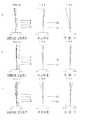
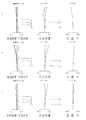
図2〜図5は、上記撮像レンズ装置の、第1〜第4の実施の形態を構成するズームレンズ系にそれぞれ対応するレンズ構成図であり、広角端(W)でのレンズ配置を光学断面で示している。各レンズ構成図中の矢印mj(j=1,2,...)は、広角端(W)から望遠端(T)へのズーミングにおける第j群(Grj)等の移動をそれぞれ模式的に示しており、矢印mFは無限遠から近接へのフォーカシングにおけるフォーカス群の移動方向を示している。また、各レンズ構成図中、ri(i=1,2,3,...)が付された面は物体側から数えてi番目の面であり、riに*印が付された面は非球面である。di(i=1,2,3,...)が付された軸上面間隔は、物体側から数えてi番目の軸上面間隔のうち、ズーミングにおいて変化する可変間隔である。なお、図2〜図5のそれぞれのレンズ構成図は、便宜上、光軸が折り曲げられておらず、一直線上にレンズが配置されている。したがって、折り曲げのための直角プリズムREF1の形状および反射ミラーREF2は図示されていない。
【0022】
各実施形態のズームレンズ系はいずれも、物体側から順に、正のパワーを有する第1レンズ群(Gr1)と、負のパワーを有する第2レンズ群と(Gr2)、正のパワーを有する第3レンズ群(Gr3)と、正のパワーを有する第4レンズ群(Gr4)と、を有する。広角端[W]から望遠端[T]への変倍時に、第2レンズ群(Gr2)は広角端[W]での位置よりも常に像面側に位置するように移動し(バリエータ)、第4レンズ群は第2レンズ群の移動に伴う像点移動を補正するように移動し(コンペンセータ)、各レンズ群の間隔を変えることにより変倍を行う構成となっている。
【0023】
そして、固体撮像素子(例えばCCD)を備えたカメラ(例えばデジタルスチルカメラ)に用いられるズームレンズ系として、その像面側には光学的ローパスフィルタ等に相当するガラス製の平行平面板(LPF)が配置されている。いずれの実施の形態においても、第1レンズ群(Gr1)は、物体側から順に少なくとも1枚の負レンズと光軸を折り曲げるための直角プリズム(REF1)と、2枚の正レンズとを含むレンズで構成されている。また、第2レンズ群(Gr2)と第3レンズ群(Gr3)には接合レンズが用いられている。各実施の形態のレンズ構成をさらに詳しく以下に説明する。なお、図2〜図5の最も像面側に配置されている平行平面板は撮像素子(SR)のカバーガラスである。
【0024】
《第1の実施の形態(図2、正負正正負)》第1の実施の形態のズームレンズ系は正・負・正・正・負の5群ズームレンズであり、各レンズ群は物体側から順に以下のように構成されている。第1レンズ群(Gr1)は、像面側に凹の負メニスカスレンズと、光軸を90°折り曲げるための第1の反射部材である直角プリズムREF1(図2では平行平板で表示)と、両凸の正レンズと、物体側に凸の正メニスカスレンズ(略平凸レンズ)と、で構成されている。第2レンズ群(Gr2)は、両面非球面を有する負レンズと物体側に両凹の負レンズ及び両凸の正レンズから成る接合レンズと、で構成されており、第2の光軸(AX2)上に配置される。第3レンズ群(Gr3)は、絞り(SP)と、両凸の正レンズと、両凸の正レンズ及び物体側に凹の負メニスカスレンズから成る接合レンズと、で構成されている。両凸の正レンズと接合レンズとの間(d16)に反射ミラーREF2(図示しない)が配置される。第4レンズ群(Gr4)は、物体側に非球面を有し物体側に凸の負メニスカスレンズと、両凸の正レンズと、で構成されており、第3の光軸(AX3)上に配置される。第5レンズ群(Gr5)は、両面非球面を有し物体側に凹の負メニスカスレンズで構成されている。
【0025】
《第2の実施の形態(図3、正負正正正)》第2の実施の形態のズームレンズ系は正・負・正・正・正の5群ズームレンズであり、各レンズ群は物体側から順に以下のように構成されている。第1レンズ群(Gr1)は、像面側に凹の負メニスカスレンズと、光軸を90°折り曲げるための第1の反射部材である直角プリズムREF1(図3では平行平板で表示)と、両凸の正レンズと、物体側に凸の正メニスカスレンズと、で構成されている。第2レンズ群(Gr2)は、両面非球面を有する負レンズと両凹の負レンズ及び両凸の正レンズから成る接合レンズと、で構成されており、第2の光軸(AX2)上に配置される。第3レンズ群(Gr3)は、絞り(SP)と、両凸の正レンズと、両凸の正レンズ及び物体側に凹の負メニスカスレンズから成る接合レンズと、で構成されている。両凸の正レンズと接合レンズとの間(d16)に反射ミラーREF2(図示しない)が配置される。第4レンズ群(Gr4)は、物体側に非球面を有し物体側に凸の負メニスカスレンズと、物体側に凸の正メニスカスレンズと、で構成されており、第3の光軸(AX3)上に配置される。第5レンズ群(Gr5)は、両面非球面を有し物体側に凹の正メニスカスレンズで構成されている。
【0026】
《第3の実施の形態(図4、正負正正)》第3の実施の形態のズームレンズ系は正・負・正・正の4群ズームレンズであり、各レンズ群は物体側から順に以下のように構成されている。第1レンズ群(Gr1)は、像面側に凹の負メニスカスレンズと、光軸を90°折り曲げるための第1の反射部材である直角プリズムREF1(図4では平行平板で表示)と、両凸の正レンズと、物体側に凸の正メニスカスレンズと、で構成されている。第2レンズ群(Gr2)は、両面非球面を有する負レンズと物体側に凹の負メニスカスレンズ及び像面側に凸の正メニスカスレンズから成る接合レンズと、で構成されており、第2の光軸(AX2)上に配置される。第3レンズ群(Gr3)は、絞り(SP)と、物体側に凸面をもつ正のメニスカスレンズ(略平凸レンズ)と、両凸の正レンズ及び物体側に両凹の負レンズから成る接合レンズと、で構成されている。正レンズと接合レンズとの間(d16)に反射ミラーREF2(図示しない)が配置される。第4レンズ群(Gr4)は、物体側に非球面を有し物体側に凸の負メニスカスレンズと、両凸の正レンズと、で構成されており、第3の光軸(AX3)上に配置される。
【0027】
《第4の実施の形態(図5、正負正正正)》第4の実施の形態のズームレンズ系は正・負・正・正・正の5群ズームレンズであり、各レンズ群は物体側から順に以下のように構成されている。第1レンズ群(Gr1)は、像面側に凹の負メニスカスレンズと、光軸を90°折り曲げるための第1の反射部材である直角プリズムREF1(図5では平行平板で表示)と、両凸の正レンズと、両凸の正レンズと、で構成されている。第2レンズ群(Gr2)は、両面非球面を有する負レンズと両凹の負レンズ及び両凸の正レンズから成る接合レンズと、で構成されており、第2の光軸(AX2)上に配置される。第3レンズ群(Gr3)は、絞り(SP)と、両凸の正レンズと、両凸の正レンズ及び両凹の負レンズから成る接合レンズと、で構成されている。接合レンズの像側(d19)に反射ミラーREF2(図示しない)が配置される。第4レンズ群(Gr4)は、物体側に非球面を有し物体側に凸の負メニスカスレンズと、両凸の正レンズと、で構成されており、第3の光軸(AX3)上に配置される。第5レンズ群(Gr5)は、両面非球面を有し物体側に凸の正メニスカスレンズで構成されている。
【0028】
上記第1、第2および第4の実施の形態では、広角端[W]から望遠端[T]への変倍時に、第1レンズ群(Gr1)、第3レンズ群(Gr3)および第5レンズ群(Gr5)の位置は固定で、第2レンズ群(Gr2)が広角端[W]での位置よりも常に像面側に位置するように第2の光軸上を移動し、第4のレンズ群(Gr4)は、第3の光軸上を物体側に移動した後、像面側にUターンする。
【0029】
上記第3の実施の形態では、広角端[W]から望遠端[T]への変倍時に、第1レンズ群(Gr1)および第3レンズ群(Gr3)の位置は固定で、第2レンズ群(Gr2)が広角端[W]での位置よりも常に像面側に位置するように第2の光軸上を移動し、第4のレンズ群(Gr4)は、第3の光軸上を物体側に移動した後、像面側にUターンする。
【0030】
上記の説明のように、いずれの実施の形態においても、第2の光軸(AX2)上を第2レンズ群(Gr2)が移動し、第3の光軸(AX3)上を第4レンズ群(Gr4)が移動することで、変倍が行われる。各移動群が異なる光軸上に配置されており、各移動機構が独立して構成できるため、簡略で小型な鏡胴構成が可能となる。
【0031】
また、第1の反射部材を含み物体光が入射する第1レンズ群(Gr1)は位置固定で、第2レンズ群が(Gr2)が第2の光軸上を移動し、第4レンズ群(Gr4)が第3の光軸上を移動するインナーズーム方式のため、ズーミングにおいてレンズの飛び出しがなく、いつもカメラがフラットな状態で撮影ができる。
【0032】
ズームレンズ系は以下に示す条件式を満たすことが望ましい。これにより、コンパクト性に優れた高倍率のズームレンズ系を実現することができる。なお、以下に説明する個々の条件をそれぞれ単独に満たせば、それに対応する作用効果を達成することは可能であるが、複数の条件を満たす方が、光学性能,小型化等の観点からより望ましいことはいうまでもない。
【0033】
以下の条件式(1)を満足することが望ましい。
0.3< D2 / fw <3 (1)
ただし、
D2:絞りと第2反射部材の反射面との距離、
fw:広角端でのズームレンズ系の焦点距離、
である。
条件式(1)は、絞りと第2反射面との距離を規定する条件である。条件式(1)の上限値を超えると絞りと第2反射面との距離が大きくなりすぎるため、反射部材が大きくなり、小型化という面で好ましくない。条件式(1)の下限値を下回ると絞りと第2反射面との距離が近づきすぎるため折り返しが困難になる。
【0034】
条件式(1)は、さらに
0.8< D2 / fw <2.5 (1)´
であることがより好ましい。条件式(1)´により、第2の反射部材をより小型化できるとともに、絞りと第2反射面との干渉条件が緩和され、より自由なレンズ構成が可能となり収差補正が容易になる。
【0035】
また、以下の、条件式(2)を満足することが望ましい。
2<|fa1 / fw|<8 (2)
ただし、
fa1:第1反射面より物体側の群の焦点距離、
fw:広角端での焦点距離、
である。
条件式(2)は第1反射面より物体側の群の焦点距離を規定する条件である。条件式(2)の下限値を下回ると第1反射面より物体側の群の焦点距離(絶対値)が小さくなり過ぎるため、歪曲収差特に広角側での負の歪曲収差が著しくなり、良好な光学性能を確保することが困難になる。逆に条件式(2)の上限を超えると、第1反射面より物体側の群の焦点距離(絶対値)が大きくなりすぎる。その結果、第1群のレンズ系および反射部材の大型化を招き、コンパクト化という点では好ましくない。
【0036】
条件式(2)は、さらに、
4<|fa1/fw|<6.5 (2)´
であることがより好ましく、そうすることで、より良好な光学性能とコンパクト化の両立が可能となる。
【0037】
また、レンズ重量のできるだけ小さい群でフォーカシングを行うことが望ましいので、フォーカス群としてはレンズ枚数が少なくレンズ径の小さい第4レンズ群(Gr4)が好ましい。
【0038】
また、各実施の形態のように、第2レンズ群(Gr2)中に非球面を配置することが望ましく、第2レンズ群中(Gr2)に非球面を配置することによって、像面湾曲収差を良好に補正することができる。また、各実施の形態のように、第4レンズ群(Gr4)中に非球面を配置することが望ましく、第4レンズ群中(Gr4)に非球面を配置することによって、像面湾曲収差や球面収差等さまざまな収差を良好に補正することができる。さらに、第5レンズ群(Gr5)中に非球面を配置することが望ましく、第5レンズ群中(Gr5)に非球面を配置することによって、さらに、像面湾曲収差を良好に補正することができる。
【0039】
なお、第1〜第4の実施の形態を構成している各レンズ群は、入射光線を屈折により偏向させる屈折型レンズ(つまり、異なる屈折率を有する媒質同士の界面で偏向が行われるタイプのレンズ)のみで構成されているが、これに限らない。例えば、回折により入射光線を偏向させる回折型レンズ、回折作用と屈折作用との組み合わせで入射光線を偏向させる屈折・回折ハイブリッド型レンズ、入射光線を媒質内の屈折率分布により偏向させる屈折率分布型レンズ等で、各レンズ群を構成してもよい。
【0040】
さらに、各実施の形態ではズームレンズ系の最終面と撮像素子との間に配置される平行平面板形状の光学的ローパスフィルタの構成例を示したが、このローパスフィルタとしては、所定の結晶軸方向が調整された水晶等を材料とする複屈折型ローパスフィルタや、必要とされる光学的な遮断周波数の特性を回折効果により達成する位相型ローパスフィルタ等が適用可能である。
【0041】
【実施例】
以下、本発明を実施した撮像レンズ装置に用いられるズームレンズ系の構成等を、コンストラクションデータ等を挙げて、更に具体的に説明する。なお、以下に挙げる実施例1〜4は、前述した第1〜第4の実施の形態にそれぞれ対応しており、第1〜第4の実施の形態を表すレンズ構成図(図2〜図5)は、対応する実施例1〜4のレンズ構成をそれぞれ示している。
【0042】
各実施例のコンストラクションデータにおいて、ri(i=1,2,3,...)は物体側から数えてi番目の面の曲率半径、di(i=1,2,3,...)は物体側から数えてi番目の軸上面間隔を示しており、Ni(i=1,2,3,...),vi(i=1,2,3,...)は物体側から数えてi番目の光学要素のd線に対する屈折率(Nd),アッベ数(vd)をそれぞれ示している。また、コンストラクションデータ中、ズーミングにおいて変化する軸上面間隔は、広角端(短焦点距離端)[W]〜ミドル(中間焦点距離状態)[M]〜望遠端(長焦点距離端)[T]での可変空気間隔である。各焦点距離状態[W],[M],[T]に対応する全系の焦点距離(f)及びFナンバー(FNO)を併せて示し、また、条件式対応値を表1に示す。また、近接撮影時のフォーカシングにおける第4レンズ群(Gr4)の移動量(フォーカスデータ)を表2に示す。実施例1〜3においては近接撮影状態の撮影距離(物点〜像点)D=0.37mであり、実施例4は近接撮影状態の撮影距離(物点〜像点)D=0.67mである。
【0043】
曲率半径riに*印が付された面は、非球面で構成された面であることを示し、非球面の面形状を表わす以下の式(AS)で定義されるものとする。各非球面の非球面データを他のデータと併せて示す。
X(H)=(C・H2)/{1+√(1−ε・C2・H2)}+(A4・H4+A6・H6+A8・H8+A10・H10) (AS)
ただし、式(AS)中、
X(H) :高さHの位置での光軸方向の変位量(面頂点基準)、
H :光軸に対して垂直な方向の高さ、
C :近軸曲率、
ε :2次曲面パラメータ、
Ai :i次の非球面係数、
である。
【0044】
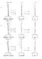
図6〜図13は実施例1〜実施例4にそれぞれ対応する収差図であり、図6〜図9は実施例1〜実施例4にそれぞれ対応する無限遠撮影状態での収差図、図10〜図13は実施例1〜実施例4にそれぞれ対応する近接撮影状態での収差図である。実施例1〜3においては近接撮影状態の撮影距離(物点〜像点)D=0.37mであり、実施例4は近接撮影状態の撮影距離(物点〜像点)D=0.67mである。図6〜図13中、[W]は広角端,[M]はミドル,[T]は望遠端における諸収差(左から順に、球面収差等,非点収差,歪曲収差である。Y’:最大像高)を示している。球面収差図において、実線(d)はd線に対する球面収差、一点鎖線(g)はg線に対する球面収差、二点鎖線(c)はc線に対する球面収差、破線(SC)は正弦条件を表している。非点収差図において、破線(DM)はメリディオナル面でのd線に対する非点収差を表しており、実線(DS)はサジタル面でのd線に対する非点収差を表わしている。また、歪曲収差図において実線はd線に対する歪曲%を表している。
【0045】
【表1】
【表2】
なお、第1〜第4の実施の形態では、第1の反射部材に直角プリズムを、第2の反射部材に反射ミラーを使用しているが、反射部材はこれに限らない。例えば、第1の反射部材に反射ミラーを、第2の反射部材にプリズムを用いてもよく、反射ミラーは表面鏡でも裏面鏡でもよい。また反射部材は反射面に光学的パワーを持ってもよく、また反射型回折素子であってもよい。
【0052】
また、第1〜第4の実施の形態の撮像レンズ装置に対応する各デジタルカメラ1の構成は、図1で示した構成と同様であり、撮像レンズ装置以外に差異はない。
【0053】
【発明の効果】
以上説明したように、本発明によれば、高画質を満足しつつ、ズームレンズ系の小型化、高変倍化を達成した撮像レンズ装置を実現することが出来る。特に、本発明の撮像レンズ装置は、入射光軸を第1の反射面により光軸を略90°折り曲げ、さらに第2の反射面により光軸を折り曲げているため、非常にコンパクトな撮像レンズ装置が実現できる。
【0054】
また、本発明の撮像レンズ装置は、ズーミングにおいて、第1の反射面と絞りと第2の反射面とは位置固定で、第1の反射面と第2の反射面との間に配置された第1の移動レンズ群と、第2の反射面の像側に配置された第2の移動レンズ群とを移動させるため、鏡胴構成が簡略化でき、コンパクト化と低コスト化が可能となる。また、インナーズーム方式のため、撮影中にレンズが飛び出すことはない。
【0055】
さらに、上記撮像レンズ装置をデジタルカメラ、ビデオカメラ、その他電子機器(例えば、パーソナルコンピュータ、モバイルコンピュータ、携帯電話、情報携帯端末等)に内蔵または外付けされるカメラに適用し、これらの機器のコンパクト化(薄型化)、高変倍率化および高画質化を図ることができる。
【図面の簡単な説明】
【図1】デジタルカメラの内部構成の概略を示す図である。
【図2】第1の実施の形態(実施例1)のレンズ構成図である。
【図3】第2の実施の形態(実施例2)のレンズ構成図である。
【図4】第3の実施の形態(実施例3)のレンズ構成図である。
【図5】第4の実施の形態(実施例4)のレンズ構成図である。
【図6】実施例1の無限遠撮影状態での収差図である。
【図7】実施例2の無限遠撮影状態での収差図である。
【図8】実施例3の無限遠撮影状態での収差図である。
【図9】実施例4の無限遠撮影状態での収差図である。
【図10】実施例1の近接撮影状態(D=0.37m)での収差図である。
【図11】実施例2の近接撮影状態(D=0.37m)での収差図である。
【図12】実施例3の近接撮影状態(D=0.37m)での収差図である。
【図13】実施例4の近接撮影状態(D=0.67m)での収差図である。
【図14】本発明に係るデジタルカメラの概略外観図である。
【符号の説明】
TL 撮像レンズ系(ズームレンズ系)
SR 撮像素子
LPF ローパスフィルタ(平行平面板)
AX1 第1の光軸(入射光軸)
AX2 第2の光軸
AX3 第3の光軸
REF1 第1の反射部材(直角プリズム)
REF2 第2の反射部材(反射ミラー)
MVL1 第1の可動レンズ
MVL2 第2の可動レンズ
CVR カメラの筐体
Gr1 第1レンズ群
Gr2 第2レンズ群
SP 絞り
Gr3 第3レンズ群
Gr4 第4レンズ群
Gr5 第5レンズ群
1 デジタルカメラ
2 筐体
3 レリーズボタン
4 液晶モニター(LCD)
5 操作ボタン
6 撮像レンズ装置
7 信号処理部
8 メモリ
9 操作部
10 コントローラ[0001]
TECHNICAL FIELD OF THE INVENTION
The present invention relates to an imaging lens device, and more particularly, to an imaging lens device having a compact and high-magnification zoom lens system suitable for digital input / output devices such as digital cameras and digital video cameras. Further, the present invention relates to a digital camera provided with such an imaging lens device.
[0002]
[Prior art]
2. Description of the Related Art In recent years, with the spread of personal computers and the like, digital still cameras, digital video cameras, and the like (hereinafter, referred to as digital cameras) that can easily capture image information into digital devices have become widespread at the individual user level. Such digital cameras are expected to be increasingly used as image information input devices in the future.
[0003]
Incidentally, the image quality of a digital camera is generally determined by the number of pixels of a solid-state imaging device such as a CCD (Charge Coupled Device). At present, digital cameras for general use have a high pixel count exceeding one million pixels, and are approaching silver halide cameras in terms of image quality. In these general digital cameras, it is also desired to perform zooming of images, particularly optical zooming with little image degradation, and in recent years, there has been a demand for zoom lenses for digital cameras that are small, have high zooming ratios, and satisfy high image quality. It is becoming.
[0004]
With regard to miniaturization, the optical system is bent by inserting a prism or a reflection mirror between the lenses, thereby further miniaturizing in the optical axis direction.
[0005]
[Patent Document 1] JP-A-6-107070
[Patent Document 2] European Patent No. 0906587B1
[Problems to be solved by the invention]
However, the optical systems described in
[0006]
In view of the above problems, an object of the present invention is to provide a completely new imaging lens device having a zoom lens system that satisfies a high zoom ratio and high image quality. Also, a digital camera provided with such an imaging lens device is provided.
[0007]
[Means for Solving the Problems]
In order to achieve the above object, an imaging lens device according to a first aspect of the present invention includes a zoom lens system that includes a plurality of groups and performs zooming by changing a group interval, and converts an optical image formed by the zoom lens system into an electric signal. An imaging lens device comprising: an imaging element that performs conversion; the zoom lens system includes, in order from the object side, a first reflecting surface, a first moving lens group, a second reflecting surface, and a second reflecting surface. A moving lens group, the incident optical axis is bent by approximately 90 ° by the first reflecting surface, and further the optical axis is bent by the second reflecting surface. In zooming, the first reflecting surface and the second reflecting surface are bent. The surface is fixed in position, and the first movable lens group and the second movable lens group move on the optical axis.
[0008]
In the imaging lens device according to a second aspect of the present invention, in the configuration of the first aspect, the first moving unit has a negative optical power, and the second moving unit has a positive optical power.
[0009]
An imaging lens device according to a third aspect of the present invention includes a zoom lens system that includes a plurality of groups and performs zooming by changing a group interval, and an imaging device that converts an optical image formed by the zoom lens system into an electric signal. The zoom lens system includes, in order from the object side, a first reflecting surface, a stop, and a second reflecting surface, and an incident optical axis is substantially defined by the first reflecting surface. The optical axis is bent by 90 ° and further bent by the second reflecting surface. During zooming, the first reflecting surface, the stop, and the second reflecting surface are fixed in position, and the stop and the second reflecting surface are Is D2, and the focal length of the zoom lens system at the wide-angle end is fw,
0.3 <D2 / fw <3
To be satisfied.
[0010]
The imaging lens device according to a fourth aspect of the present invention is the image pickup lens device according to the third aspect, wherein the first movement having a negative optical power is disposed between the first reflection surface and the second reflection surface. A lens group having a second moving lens group having a positive optical power and located closer to the image side than the second reflecting surface, wherein the first reflecting surface has a positive optical power include.
[0011]
An imaging lens device according to a fifth aspect is the imaging lens device according to the first or third aspect, wherein the following conditional expression is satisfied.
2 <| fa1 / fw | <8
However,
fa1: focal length of the group closer to the object side than the first reflecting surface,
fw: focal length of the zoom lens system at the wide-angle end,
It is.
[0012]
According to a sixth aspect of the present invention, in the imaging lens device according to the first or fourth aspect, focusing is performed by movement of the second moving group.
[0013]
According to a seventh aspect of the invention, there is provided a digital camera including the imaging lens device having the configuration according to any one of the first to sixth aspects.
[0014]
BEST MODE FOR CARRYING OUT THE INVENTION
Hereinafter, an imaging lens device embodying the present invention will be described with reference to the drawings. 2. Description of the Related Art An imaging lens device that optically captures an image of a subject and outputs the signal as an electrical signal is a camera used for capturing a still image or a moving image of a subject. For example, a digital camera; a video camera; a digital video unit; a personal computer; It is a main component of the camera} built in or external to a computer, a mobile phone, a personal digital assistant (PDA) or the like.
[0015]
FIG. 14 is a schematic external view of a digital camera according to the present invention. FIG. 14A is a front view of the digital camera, and FIG. 14B is a rear view of the digital camera. The
[0016]
FIG. 1 is a diagram schematically showing the internal configuration of a digital camera. FIG. 1A corresponds to a front view of the digital camera, and FIG. 1B corresponds to a side view of an imaging lens device. The subject is located on the near side of the drawing in FIG. 1A, and on the left side of the drawing in FIG. 1B. In FIG. 1, a line indicated by a two-dot chain line represents the
[0017]
As the image pickup device (SR), for example, a solid-state image pickup device such as a CCD composed of a plurality of pixels or a CMOS (Complementary Metal Oxide Semiconductor) sensor is used, and an optical image formed by an image pickup lens system (TL) is used as an electric signal. Is converted to An optical image to be formed by the imaging lens system (TL) passes through an optical low-pass filter (LPF) having a predetermined cut-off frequency characteristic determined by the pixel pitch of the imaging device (SR), thereby electrically connecting the optical image. The spatial frequency characteristic is adjusted so that the so-called aliasing noise generated when the signal is converted into a natural signal is minimized.
[0018]
The signal generated by the image sensor (SR) is subjected to predetermined analog image processing, digital image processing, image compression processing, and the like by the
[0019]
Next, the imaging lens system (TL) will be described with reference to FIG. The imaging lens system (TL) is a zoom lens system. The first optical axis (AX1), which is the incident optical axis, is bent by 90 ° by the first reflecting member (REF1). On the second optical axis (AX2) bent by the first reflecting member (REF1), a first moving lens group (MVL1) and a stop (SP) are arranged. The second optical axis (AX2) is further bent by 90 ° in a direction perpendicular to the first optical axis by the second reflecting member (REF2). A second moving lens group (MVL2) is arranged on the third optical axis (AX3) bent by the second reflecting member (REF2). The first optical axis (AX1), the second optical axis (AX2), and the third optical axis (AX3) are perpendicular to each other. In zooming of the imaging lens system (TL), the first reflecting member (REF1), the stop (SP), and the second reflecting member (REF2) are fixed in position, and the first moving lens is moved on the second optical axis. The group (MVL1) moves along the third optical axis with the second moving lens group (MVL2). The movement of these moving lens groups is controlled by the
[0020]
The
[0021]
FIGS. 2 to 5 are lens configuration diagrams respectively corresponding to the zoom lens systems constituting the first to fourth embodiments of the imaging lens device, and show the lens arrangement at the wide-angle end (W) in an optical cross section. Indicated by. Arrows mj (j = 1, 2,...) In each lens configuration diagram schematically show movement of the j-th group (Grj) and the like during zooming from the wide-angle end (W) to the telephoto end (T). The arrow mF indicates the moving direction of the focus group in focusing from infinity to proximity. In each lens configuration diagram, the surface marked with ri (i = 1, 2, 3,...) Is the i-th surface counted from the object side, and the surface marked with * for ri is It is an aspheric surface. The axial top surface interval to which di (i = 1, 2, 3,...) is a variable interval that changes during zooming, of the i-th axial top surface interval counted from the object side. In each of the lens configuration diagrams of FIGS. 2 to 5, the optical axis is not bent for convenience, and the lenses are arranged in a straight line. Therefore, the shape of the right-angle prism REF1 for bending and the reflection mirror REF2 are not shown.
[0022]
In each of the zoom lens systems according to the embodiments, in order from the object side, a first lens group (Gr1) having a positive power, a second lens group (Gr2) having a negative power, and a second lens group (Gr2) having a positive power. It has a third lens group (Gr3) and a fourth lens group (Gr4) having positive power. At the time of zooming from the wide-angle end [W] to the telephoto end [T], the second lens unit (Gr2) moves (variator) so that it is always positioned closer to the image plane than at the wide-angle end [W]. The fourth lens group is configured to move (compensator) so as to correct the image point movement accompanying the movement of the second lens group, and to perform zooming by changing the interval between the lens groups.
[0023]
As a zoom lens system used for a camera (for example, a digital still camera) provided with a solid-state imaging device (for example, a CCD), a glass parallel plane plate (LPF) corresponding to an optical low-pass filter or the like is provided on the image plane side. Is arranged. In any of the embodiments, the first lens group (Gr1) includes, in order from the object side, at least one negative lens, a right-angle prism (REF1) for bending the optical axis, and two positive lenses. It is composed of A cemented lens is used for the second lens group (Gr2) and the third lens group (Gr3). The lens configuration of each embodiment will be described in more detail below. Note that the parallel plane plate disposed closest to the image plane in FIGS. 2 to 5 is a cover glass of the image sensor (SR).
[0024]
<< First Embodiment (FIG. 2, positive / negative / positive / positive / negative) >> The zoom lens system according to the first embodiment is a five-unit positive / negative / positive / positive / negative zoom lens. It is configured as follows in order from. The first lens group (Gr1) includes a negative meniscus lens concave on the image plane side and a right-angle prism REF1 (shown as a parallel plate in FIG. 2) as a first reflecting member for bending the optical axis by 90 °. It comprises a convex positive lens and a positive meniscus lens (substantially plano-convex lens) convex on the object side. The second lens group (Gr2) is composed of a negative lens having an aspheric surface on both sides, and a cemented lens composed of a negative lens that is biconcave and a positive lens that is biconvex on the object side, and has a second optical axis (AX2). ). The third lens group (Gr3) includes a stop (SP), a biconvex positive lens, and a cemented lens including a biconvex positive lens and a negative meniscus lens concave on the object side. A reflection mirror REF2 (not shown) is arranged between the biconvex positive lens and the cemented lens (d16). The fourth lens group (Gr4) includes a negative meniscus lens having an aspheric surface on the object side and convex on the object side, and a biconvex positive lens, and is disposed on the third optical axis (AX3). Be placed. The fifth lens group (Gr5) includes a negative meniscus lens having an aspheric surface on both sides and concave on the object side.
[0025]
<< Second Embodiment (FIG. 3, positive / negative / positive / positive / positive) >> The zoom lens system according to the second embodiment is a five-unit zoom lens of positive, negative, positive, positive and positive. It is configured as follows in order from the side. The first lens group (Gr1) includes a negative meniscus lens concave on the image plane side and a right-angle prism REF1 (shown as a parallel plate in FIG. 3) as a first reflecting member for bending the optical axis by 90 °. It is composed of a convex positive lens and a positive meniscus lens convex on the object side. The second lens group (Gr2) is composed of a negative lens having an aspheric surface on both sides, and a cemented lens composed of a biconcave negative lens and a biconvex positive lens, and is disposed on the second optical axis (AX2). Be placed. The third lens group (Gr3) includes a stop (SP), a biconvex positive lens, and a cemented lens including a biconvex positive lens and a negative meniscus lens concave on the object side. A reflection mirror REF2 (not shown) is arranged between the biconvex positive lens and the cemented lens (d16). The fourth lens group (Gr4) includes a negative meniscus lens having an aspheric surface on the object side and convex on the object side, and a positive meniscus lens convex on the object side, and has a third optical axis (AX3). ). The fifth lens group (Gr5) is configured by a positive meniscus lens having an aspheric surface on both sides and concave on the object side.
[0026]
<< Third Embodiment (FIG. 4, Positive, Negative, Positive and Positive) >> The zoom lens system according to the third embodiment is a four-unit positive, negative, positive and positive zoom lens, and each lens unit is arranged in order from the object side. It is configured as follows. The first lens group (Gr1) includes a negative meniscus lens concave on the image plane side and a right-angle prism REF1 (represented by a parallel plate in FIG. 4) as a first reflecting member for bending the optical axis by 90 °. It is composed of a convex positive lens and a positive meniscus lens convex on the object side. The second lens group (Gr2) includes a negative lens having an aspheric surface on both surfaces, a cemented lens including a negative meniscus lens concave on the object side, and a positive meniscus lens convex on the image plane side. It is arranged on the optical axis (AX2). The third lens group (Gr3) includes a stop (SP), a positive meniscus lens having a convex surface on the object side (substantially plano-convex lens), a cemented lens including a biconvex positive lens and a biconcave negative lens on the object side. And is composed of A reflection mirror REF2 (not shown) is arranged between the positive lens and the cemented lens (d16). The fourth lens group (Gr4) includes a negative meniscus lens having an aspheric surface on the object side and convex on the object side, and a biconvex positive lens, and is disposed on the third optical axis (AX3). Be placed.
[0027]
<< Fourth Embodiment (FIG. 5, Positive, Negative, Positive, Positive, Positive) >> The zoom lens system according to the fourth embodiment is a positive, negative, positive, positive, positive and positive five-unit zoom lens, and each lens unit is an object. It is configured as follows in order from the side. The first lens group (Gr1) includes a negative meniscus lens concave on the image plane side and a right-angle prism REF1 (shown as a parallel plate in FIG. 5) as a first reflecting member for bending the optical axis by 90 °. It is composed of a convex positive lens and a biconvex positive lens. The second lens group (Gr2) is composed of a negative lens having an aspheric surface on both sides, and a cemented lens composed of a biconcave negative lens and a biconvex positive lens, and is disposed on the second optical axis (AX2). Be placed. The third lens group (Gr3) includes a stop (SP), a biconvex positive lens, and a cemented lens including a biconvex positive lens and a biconcave negative lens. A reflection mirror REF2 (not shown) is arranged on the image side (d19) of the cemented lens. The fourth lens group (Gr4) includes a negative meniscus lens having an aspheric surface on the object side and convex on the object side, and a biconvex positive lens, and is disposed on the third optical axis (AX3). Be placed. The fifth lens group (Gr5) is composed of a positive meniscus lens having an aspheric surface on both sides and convex on the object side.
[0028]
In the first, second, and fourth embodiments, at the time of zooming from the wide-angle end [W] to the telephoto end [T], the first lens unit (Gr1), the third lens unit (Gr3), and the fifth lens unit (Gr3). The position of the lens group (Gr5) is fixed, and the second lens group (Gr2) is moved on the second optical axis so that it is always positioned closer to the image plane than at the wide-angle end [W]. The lens unit (Gr4) makes a U-turn to the image plane side after moving on the third optical axis to the object side.
[0029]
In the third embodiment, at the time of zooming from the wide-angle end [W] to the telephoto end [T], the positions of the first lens unit (Gr1) and the third lens unit (Gr3) are fixed and the second lens unit (Gr3) is fixed. The fourth lens group (Gr4) moves on the third optical axis so that the group (Gr2) is always positioned closer to the image plane than the position at the wide-angle end [W]. Is moved to the object side, and then a U-turn is made to the image plane side.
[0030]
As described above, in any of the embodiments, the second lens group (Gr2) moves on the second optical axis (AX2), and the fourth lens group moves on the third optical axis (AX3). The magnification is changed by moving (Gr4). Since each moving group is arranged on a different optical axis, and each moving mechanism can be configured independently, a simple and small lens barrel configuration can be realized.
[0031]
The first lens group (Gr1) including the first reflection member and on which object light is incident is fixed in position, the second lens group (Gr2) moves on the second optical axis, and the fourth lens group (Gr1) moves. Since Gr4) moves on the third optical axis, the lens does not pop out during zooming, so that the camera can always shoot in a flat state.
[0032]
It is desirable that the zoom lens system satisfies the following conditional expressions. As a result, a high-power zoom lens system having excellent compactness can be realized. It is possible to achieve the corresponding effects if the individual conditions described below are satisfied individually, but it is more preferable to satisfy a plurality of conditions from the viewpoint of optical performance, miniaturization, and the like. Needless to say.
[0033]
It is desirable to satisfy the following conditional expressions (1).
0.3 <D2 / fw <3 (1)
However,
D2: distance between the stop and the reflecting surface of the second reflecting member,
fw: focal length of the zoom lens system at the wide-angle end,
It is.
Conditional expression (1) is a condition for defining the distance between the stop and the second reflecting surface. If the value exceeds the upper limit of conditional expression (1), the distance between the stop and the second reflecting surface becomes too large, and the size of the reflecting member increases, which is not preferable in terms of miniaturization. When the value goes below the lower limit of conditional expression (1), the distance between the stop and the second reflecting surface becomes too short, so that it becomes difficult to turn back.
[0034]
Conditional expression (1) further defines
0.8 <D2 / fw <2.5 (1) '
Is more preferable. By the conditional expression (1) ′, the size of the second reflecting member can be further reduced, and the interference condition between the stop and the second reflecting surface is relaxed, so that a more flexible lens configuration can be achieved, and aberration correction can be facilitated.
[0035]
It is desirable that the following conditional expression (2) is satisfied.
2 <| fa1 / fw | <8 (2)
However,
fa1: focal length of the group closer to the object side than the first reflecting surface,
fw: focal length at the wide-angle end,
It is.
Conditional expression (2) is a condition for defining the focal length of the group on the object side of the first reflecting surface. When the value goes below the lower limit of conditional expression (2), the focal length (absolute value) of the group on the object side from the first reflecting surface becomes too small, so that distortion, particularly negative distortion on the wide-angle side, becomes remarkable, and good It becomes difficult to ensure optical performance. Conversely, when the value exceeds the upper limit of the conditional expression (2), the focal length (absolute value) of the group on the object side of the first reflecting surface becomes too large. As a result, the first lens unit and the reflecting member are enlarged, which is not preferable in terms of compactness.
[0036]
Conditional expression (2) further satisfies
4 <| fa1 / fw | <6.5 (2) ′
Is more preferable, so that both good optical performance and compactness can be achieved.
[0037]
Since it is desirable to perform focusing with a lens group having the smallest possible lens weight, the fourth lens group (Gr4) having a small number of lenses and a small lens diameter is preferable as the focus group.
[0038]
Also, as in each embodiment, it is desirable to dispose an aspheric surface in the second lens group (Gr2), and by disposing an aspheric surface in the second lens group (Gr2), it is possible to reduce field curvature aberration. Correction can be made well. Further, as in each embodiment, it is desirable to arrange an aspherical surface in the fourth lens group (Gr4), and by arranging an aspherical surface in the fourth lens group (Gr4), it is possible to reduce the field curvature aberration and the like. Various aberrations such as spherical aberration can be satisfactorily corrected. Further, it is desirable to arrange an aspherical surface in the fifth lens group (Gr5), and by arranging an aspherical surface in the fifth lens group (Gr5), it is possible to further satisfactorily correct field curvature aberration. it can.
[0039]
Each of the lens groups constituting the first to fourth embodiments is a refraction type lens that deflects an incident light ray by refraction (that is, a type in which deflection is performed at an interface between media having different refractive indexes). Lens), but is not limited to this. For example, a diffractive lens that deflects incident light by diffraction, a hybrid refraction / diffraction lens that deflects incident light by a combination of diffraction and refraction, and a refractive index distribution type that deflects incident light by a refractive index distribution in a medium. Each lens group may be constituted by a lens or the like.
[0040]
Further, in each of the embodiments, the configuration example of the optical flat low pass filter having the shape of a plane parallel plate disposed between the final surface of the zoom lens system and the image pickup device has been described. A birefringent low-pass filter made of crystal or the like whose direction is adjusted, a phase-type low-pass filter that achieves required optical cutoff frequency characteristics by a diffraction effect, and the like can be applied.
[0041]
【Example】
Hereinafter, the configuration and the like of the zoom lens system used in the imaging lens device embodying the present invention will be described more specifically with reference to construction data and the like. Examples 1 to 4 described below correspond to the first to fourth embodiments, respectively, and are lens configuration diagrams (FIGS. 2 to 5) showing the first to fourth embodiments. ) Shows the corresponding lens configurations of Examples 1 to 4, respectively.
[0042]
In the construction data of each embodiment, ri (i = 1, 2, 3,...) Is the radius of curvature of the i-th surface counted from the object side, and di (i = 1, 2, 3,...) Represents the i-th axial upper surface distance counted from the object side, and Ni (i = 1, 2, 3,...) And vi (i = 1, 2, 3,. The refractive index (Nd) and Abbe number (vd) of the i-th optical element counted with respect to the d-line are shown. In the construction data, the distance between the upper surfaces of the axes that changes during zooming is from the wide-angle end (short focal length end) [W] to the middle (intermediate focal length state) [M] to the telephoto end (long focal length end) [T]. Is the variable air spacing. The focal length (f) and F-number (FNO) of the entire system corresponding to each focal length state [W], [M], [T] are shown together, and values corresponding to conditional expressions are shown in Table 1. Table 2 shows the amount of movement (focus data) of the fourth lens group (Gr4) in focusing during close-up shooting. In the first to third embodiments, the shooting distance (object point to image point) D = 0.37 m in the close-up shooting state, and in the fourth embodiment, the shooting distance (object point to image point) D = 0.67 m in the close-up shooting state. It is.
[0043]
A surface with a * mark on the radius of curvature ri indicates a surface constituted by an aspheric surface, and is defined by the following equation (AS) representing the surface shape of the aspheric surface. The aspherical surface data of each aspherical surface is shown together with other data.
X (H) = (CH2 ) / {1 +} (1-ε · C2 ・ H2 )} + (A4 ・ H4 + A6 · H6 + A8 · H8 + A10 · H10 ) (AS)
However, in the expression (AS),
X (H): displacement amount in the optical axis direction at the position of height H (based on surface vertex),
H: height in the direction perpendicular to the optical axis,
C: paraxial curvature,
ε: quadratic surface parameter,
Ai: i-th order aspherical coefficient,
It is.
[0044]
6 to 13 are aberration diagrams respectively corresponding to the first to fourth embodiments, and FIGS. 6 to 9 are aberration diagrams in an infinity shooting state corresponding to the first to fourth embodiments, respectively. FIG. 13 to FIG. 13 are aberration diagrams in a close-up shooting state corresponding to Examples 1 to 4, respectively. In the first to third embodiments, the shooting distance (object point to image point) D = 0.37 m in the close-up shooting state, and in the fourth embodiment, the shooting distance (object point to image point) D = 0.67 m in the close-up shooting state. It is. 6 to 13, [W] is the wide-angle end, [M] is the middle, [T] is various aberrations at the telephoto end (in order from the left, spherical aberration, astigmatism, and distortion. Y ′: (Maximum image height). In the spherical aberration diagram, the solid line (d) represents the spherical aberration with respect to the d line, the one-dot chain line (g) represents the spherical aberration with respect to the g line, the two-dot chain line (c) represents the spherical aberration with respect to the c line, and the dashed line (SC) represents the sine condition. ing. In the astigmatism diagram, a broken line (DM) indicates astigmatism with respect to the d-line on the meridional surface, and a solid line (DS) indicates astigmatism with respect to the d-line on the sagittal surface. In the distortion diagram, the solid line represents the distortion% with respect to the d-line.
[0045]
[Table 1]
[Table 2]
In the first to fourth embodiments, the right angle prism is used for the first reflecting member and the reflecting mirror is used for the second reflecting member, but the reflecting member is not limited to this. For example, a reflection mirror may be used for the first reflection member, and a prism may be used for the second reflection member. The reflection mirror may be a front surface mirror or a back surface mirror. The reflecting member may have an optical power on the reflecting surface, or may be a reflective diffractive element.
[0052]
The configuration of each
[0053]
【The invention's effect】
As described above, according to the embodiments of the present invention, it is possible to realize an imaging lens device that achieves high zoom quality while achieving high image quality while achieving a small size and high zoom ratio. In particular, the imaging lens device of the present invention has an extremely compact imaging lens device because the incident optical axis is bent by approximately 90 ° by the first reflecting surface and the optical axis is bent by the second reflecting surface. Can be realized.
[0054]
Further, in the imaging lens device of the present invention, in zooming, the first reflecting surface, the stop, and the second reflecting surface are fixed in position, and are disposed between the first reflecting surface and the second reflecting surface. Since the first movable lens group and the second movable lens group arranged on the image side of the second reflecting surface are moved, the lens barrel configuration can be simplified, and compactness and cost reduction can be achieved. . Also, because of the inner zoom method, the lens does not pop out during shooting.
[0055]
Further, the imaging lens device is applied to a camera built in or external to a digital camera, a video camera, and other electronic devices (for example, a personal computer, a mobile computer, a mobile phone, a personal digital assistant, and the like). (Thinning), high magnification, and high image quality can be achieved.
[Brief description of the drawings]
FIG. 1 is a diagram schematically illustrating an internal configuration of a digital camera.
FIG. 2 is a lens configuration diagram of a first embodiment (Example 1).
FIG. 3 is a lens configuration diagram of a second embodiment (Example 2).
FIG. 4 is a lens configuration diagram of a third embodiment (Example 3).
FIG. 5 is a lens configuration diagram of a fourth embodiment (Example 4).
FIG. 6 is an aberration diagram of the first embodiment in an infinity shooting state.
FIG. 7 is an aberration diagram for Example 2 in an infinity shooting state.
FIG. 8 is an aberration diagram for Example 3 in an infinity shooting state.
FIG. 9 is an aberration diagram for Example 4 in an infinity shooting state.
FIG. 10 is an aberration diagram in a close-up shooting state (D = 0.37 m) according to the first embodiment.
FIG. 11 is an aberration diagram in a close-up shooting state (D = 0.37 m) in the second embodiment.
FIG. 12 is an aberration diagram in a close-up shooting state (D = 0.37 m) in Example 3;
FIG. 13 is an aberration diagram for Example 4 in a close-up shooting state (D = 0.67 m).
FIG. 14 is a schematic external view of a digital camera according to the present invention.
[Explanation of symbols]
TL imaging lens system (zoom lens system)
SR image sensor
LPF low-pass filter (parallel plane plate)
AX1 First optical axis (incident optical axis)
AX2 Second optical axis
AX3 Third optical axis
REF1 First reflection member (right angle prism)
REF2 Second reflection member (reflection mirror)
MVL1 First movable lens
MVL2 Second movable lens
CVR camera housing
Gr1 first lens group
Gr2 second lens group
SP aperture
Gr3 third lens group
Gr4 fourth lens group
Gr5 5th lens group
1 Digital camera
2 Case
3 Release button
4 Liquid crystal monitor (LCD)
5 Operation buttons
6. Imaging lens device
7 Signal processing unit
8 memory
9 Operation section
10 Controller
Claims (7)
Translated fromJapaneseズームレンズ系により形成された光学像を電気信号に変換する撮像素子と、
を備えた撮像レンズ装置であって、
ズームレンズ系は、物体側から順に
第1の反射面と、第1の移動レンズ群と、第2の反射面と、第2の移動レンズ群とを含み、
入射光軸は、第1の反射面によって略90°折り曲げられ、さらに第2の反射面によって光軸が折り曲げられ、
ズーミングにおいて、
第1の反射面と第2の反射面は位置固定で、第1の移動レンズ群と、第2の移動レンズ群とが光軸上を移動することを特徴とする撮像レンズ装置。A zoom lens system consisting of a plurality of groups and performing zooming by changing the group interval,
An image sensor that converts an optical image formed by the zoom lens system into an electric signal;
An imaging lens device comprising:
The zoom lens system includes, in order from the object side, a first reflecting surface, a first moving lens group, a second reflecting surface, and a second moving lens group,
The incident optical axis is bent by approximately 90 ° by the first reflecting surface, and further bent by the second reflecting surface.
In zooming,
An imaging lens device, wherein a first reflecting surface and a second reflecting surface are fixed in position, and a first moving lens group and a second moving lens group move on an optical axis.
ズームレンズ系により形成された光学像を電気信号に変換する撮像素子と、
を備えた撮像レンズ装置であって、
ズームレンズ系は、物体側から順に、
第1の反射面と、絞りと、第2の反射面とを含み、
入射光軸は、第1の反射面によって略90°折り曲げられ、さらに第2の反射面によって光軸が折り曲げられ、
ズーミングにおいて、第1の反射面と、絞りと、第2の反射面とは位置固定で、絞りと第2の反射面との距離をD2、広角端でのズームレンズ系の焦点距離をfwとする時、
0.3< D2 / fw <3
を満足することを特徴とする撮像レンズ装置。A zoom lens system consisting of a plurality of groups and performing zooming by changing the group interval,
An image sensor that converts an optical image formed by the zoom lens system into an electric signal;
An imaging lens device comprising:
The zoom lens system, in order from the object side,
A first reflecting surface, a stop, and a second reflecting surface;
The incident optical axis is bent by approximately 90 ° by the first reflecting surface, and further bent by the second reflecting surface.
In zooming, the first reflecting surface, the diaphragm, and the second reflecting surface are fixed in position, the distance between the diaphragm and the second reflecting surface is D2, and the focal length of the zoom lens system at the wide-angle end is fw. when doing,
0.3 <D2 / fw <3
An imaging lens device characterized by satisfying the following.
前記第1の反射面は正の光学的パワーを有する群に含まれることを特徴とする請求項3に記載の撮像レンズ装置。A first moving lens group having negative optical power disposed between the first reflection surface and the second reflection surface; and a positive moving lens group disposed on the image side of the second reflection surface. A second moving lens group having optical power;
The imaging lens device according to claim 3, wherein the first reflection surface is included in a group having a positive optical power.
以下の条件式を満足することを特徴とする撮像レンズ装置。
2< |fa1 / fw| <8
ただし、
fa1:第1反射面より物体側の群の焦点距離、
fw:広角端でのズームレンズ系の焦点距離、
である。The imaging lens device according to claim 1 or 3,
An imaging lens device satisfying the following conditional expressions.
2 <| fa1 / fw | <8
However,
fa1: focal length of the group closer to the object side than the first reflecting surface,
fw: focal length of the zoom lens system at the wide-angle end,
It is.
Priority Applications (2)
| Application Number | Priority Date | Filing Date | Title |
|---|---|---|---|
| JP2002336879AJP2004170707A (en) | 2002-11-20 | 2002-11-20 | Imaging lens device and digital camera equipped with imaging lens device |
| US10/391,359US7180542B2 (en) | 2002-11-20 | 2003-03-18 | Imaging lens device and digital camera having the imaging lens device |
Applications Claiming Priority (1)
| Application Number | Priority Date | Filing Date | Title |
|---|---|---|---|
| JP2002336879AJP2004170707A (en) | 2002-11-20 | 2002-11-20 | Imaging lens device and digital camera equipped with imaging lens device |
Publications (1)
| Publication Number | Publication Date |
|---|---|
| JP2004170707Atrue JP2004170707A (en) | 2004-06-17 |
Family
ID=32290373
Family Applications (1)
| Application Number | Title | Priority Date | Filing Date |
|---|---|---|---|
| JP2002336879APendingJP2004170707A (en) | 2002-11-20 | 2002-11-20 | Imaging lens device and digital camera equipped with imaging lens device |
Country Status (2)
| Country | Link |
|---|---|
| US (1) | US7180542B2 (en) |
| JP (1) | JP2004170707A (en) |
Cited By (44)
| Publication number | Priority date | Publication date | Assignee | Title |
|---|---|---|---|---|
| WO2004107010A1 (en)* | 2003-05-30 | 2004-12-09 | Sony Corporation | Zoom lens and imaging device |
| WO2005026809A1 (en)* | 2003-09-08 | 2005-03-24 | Sony Corporation | Zoom lens and imaging device |
| JP2005321452A (en)* | 2004-05-06 | 2005-11-17 | Sony Corp | Zoom lens and image pickup apparatus |
| JP2006031002A (en)* | 2004-07-13 | 2006-02-02 | Samsung Electronics Co Ltd | Zoom lens optical system |
| JP2006098686A (en)* | 2004-09-29 | 2006-04-13 | Olympus Corp | Zoom lens and electronic imaging apparatus using the same |
| JP2006098685A (en)* | 2004-09-29 | 2006-04-13 | Olympus Corp | Zoom lens and electronic imaging apparatus using the same |
| JP2006113565A (en)* | 2004-09-16 | 2006-04-27 | Konica Minolta Opto Inc | Zoom lens and imaging apparatus |
| US7068440B1 (en) | 2005-01-12 | 2006-06-27 | Konica Minolta Photo Imaging, Inc. | Variable magnification optical system |
| JP2006171449A (en)* | 2004-12-16 | 2006-06-29 | Casio Comput Co Ltd | Imaging apparatus and electronic camera |
| JP2006323051A (en)* | 2005-05-18 | 2006-11-30 | Konica Minolta Photo Imaging Inc | Variable power optical system |
| JP2006350051A (en)* | 2005-06-17 | 2006-12-28 | Konica Minolta Photo Imaging Inc | Variable power optical system and imaging apparatus equipped therewith |
| JP2006350049A (en)* | 2005-06-17 | 2006-12-28 | Konica Minolta Photo Imaging Inc | Lens unit and imaging apparatus equipped therewith |
| JP2007033879A (en)* | 2005-07-27 | 2007-02-08 | Sony Corp | Imaging lens device and imaging apparatus |
| JP2007094135A (en)* | 2005-09-29 | 2007-04-12 | Konica Minolta Opto Inc | Zoom lens |
| JP2007094136A (en)* | 2005-09-29 | 2007-04-12 | Konica Minolta Opto Inc | Zoom lens and image pickup device |
| JP2007127703A (en)* | 2005-11-01 | 2007-05-24 | Olympus Corp | Optical system |
| JP2007148056A (en)* | 2005-11-29 | 2007-06-14 | Canon Inc | Zoom optical system |
| JP2007248952A (en)* | 2006-03-17 | 2007-09-27 | Olympus Imaging Corp | Bending variable power optical system |
| JP2007256564A (en)* | 2006-03-23 | 2007-10-04 | Fujinon Corp | Zoom lens |
| JP2008032924A (en)* | 2006-07-27 | 2008-02-14 | Nikon Corp | Zoom lens, imaging device, zoom lens zooming method, zoom lens anti-vibration method |
| JP2008102398A (en)* | 2006-10-20 | 2008-05-01 | Olympus Imaging Corp | Variable power optical system and imaging apparatus using the same |
| JP2008102399A (en)* | 2006-10-20 | 2008-05-01 | Olympus Imaging Corp | Bending variable power optical system and imaging apparatus using the same |
| US7382546B2 (en) | 2004-10-29 | 2008-06-03 | Konica Minolta Opto, Inc. | Zoom optical system, imaging lens device, and digital apparatus |
| JP2008224909A (en)* | 2007-03-09 | 2008-09-25 | Nikon Corp | Zoom lens, optical apparatus, and imaging method |
| US7446947B2 (en) | 2005-08-02 | 2008-11-04 | Konica Minolta Photo Imaging, Inc. | Variable magnification optical system and image taking apparatus provided therewith |
| JPWO2006115061A1 (en)* | 2005-04-21 | 2008-12-18 | 松下電器産業株式会社 | Imaging device and driving method of imaging optical system thereof |
| US7499224B2 (en) | 2006-03-17 | 2009-03-03 | Olympus Imaging Corp. | Bent type zoom optical system, and imager, information processor and electronic camera apparatus incorporating the same |
| JP2009048181A (en)* | 2007-07-25 | 2009-03-05 | Fujifilm Corp | Stereo imaging device |
| JP2009103852A (en)* | 2007-10-23 | 2009-05-14 | Nikon Corp | Zoom lens and optical apparatus equipped with the same |
| US7646418B2 (en) | 2005-11-16 | 2010-01-12 | Sony Corporation | Image capture apparatus and zoom lens |
| JP2010091835A (en)* | 2008-10-09 | 2010-04-22 | Nikon Corp | Zoom lens and optical equipment mounted with the same, and manufacturing method |
| JP2010091836A (en)* | 2008-10-09 | 2010-04-22 | Nikon Corp | Zoom lens and optical equipment mounted with the same, and manufacturing method |
| JP2010097127A (en)* | 2008-10-20 | 2010-04-30 | Nikon Corp | Zoom lens, optical equipment incorporating mounted with the same, and method of manufacturing the same |
| JP2010175902A (en)* | 2009-01-30 | 2010-08-12 | Nikon Corp | Variable power optical system, optical equipment having the variable power optical system, and method for manufacturing variable power optical system |
| JP2011017772A (en)* | 2009-07-07 | 2011-01-27 | Nikon Corp | Zoom lens, optical apparatus with the same mounted thereon and method for manufacturing the same |
| JP2011017773A (en)* | 2009-07-07 | 2011-01-27 | Nikon Corp | Zoom lens, optical apparatus with the same mounted thereon and method for manufacturing the same |
| JP2011070222A (en)* | 2010-12-20 | 2011-04-07 | Fujifilm Corp | Variable magnification optical system with vibration-proof function and imaging device incorporating the variable magnification optical system |
| JP2011237832A (en)* | 2011-08-25 | 2011-11-24 | Nikon Corp | Zoom lens and imaging device |
| KR101177134B1 (en)* | 2004-12-28 | 2012-08-24 | 코니카 미놀타 어드밴스드 레이어즈 인코포레이티드 | Zoom lens and image pickup device |
| KR101194471B1 (en) | 2004-09-16 | 2012-10-24 | 코니카 미놀타 어드밴스드 레이어즈 인코포레이티드 | Zoom lens and image pickup apparatus |
| US8411361B2 (en) | 2007-08-13 | 2013-04-02 | Nikon Corporation | Zoom lens, and optical apparatus and method for forming an image of an object using the zoom lens |
| US8437088B2 (en) | 2007-03-09 | 2013-05-07 | Nikon Corporation | Zoom lens, optical apparatus, and method for forming an image of an object |
| CN113237634A (en)* | 2021-04-19 | 2021-08-10 | 中国科学院西安光学精密机械研究所 | Zoom lens automatic image surface butt joint and optical axis run-out detection system and method |
| JP2023544219A (en)* | 2021-09-23 | 2023-10-20 | コアフォトニクス リミテッド | Large diameter continuous zoom bending telecamera |
Families Citing this family (38)
| Publication number | Priority date | Publication date | Assignee | Title |
|---|---|---|---|---|
| US7391460B2 (en)* | 2001-11-13 | 2008-06-24 | Olympus Corporation | Arrangement of bending optical systems in a picture taking lens unit and an optical finder unit of a camera |
| JP4088517B2 (en)* | 2002-12-10 | 2008-05-21 | コニカミノルタオプト株式会社 | Digital camera |
| US7567284B2 (en)* | 2003-06-17 | 2009-07-28 | Olympus Corporation | Encoder, lens-implement and digital camera |
| JP2005321545A (en)* | 2004-05-07 | 2005-11-17 | Sony Corp | Imaging apparatus |
| US20060017834A1 (en)* | 2004-07-23 | 2006-01-26 | Konica Minolta Opto, Inc. | Imaging optical system and imaging lens device |
| JP2006064839A (en)* | 2004-08-25 | 2006-03-09 | Konica Minolta Opto Inc | Zoom lens and imaging apparatus |
| JP4717480B2 (en)* | 2005-03-25 | 2011-07-06 | 富士フイルム株式会社 | Zoom lens |
| JP4963187B2 (en)* | 2006-04-05 | 2012-06-27 | 富士フイルム株式会社 | Imaging lens and imaging apparatus |
| DE102006045565B3 (en)* | 2006-08-04 | 2008-06-26 | Leica Camera Ag | Wide-angle viewfinder on rangefinder cameras for photographing with different focal lengths |
| JP2009086175A (en)* | 2007-09-28 | 2009-04-23 | Fujifilm Corp | LENS DEVICE AND IMAGING DEVICE |
| JP2012013769A (en)* | 2010-06-29 | 2012-01-19 | Canon Inc | Imaging apparatus |
| CN102692804B (en)* | 2011-03-21 | 2015-06-03 | 联想(北京)有限公司 | Display screen and terminal device |
| US9857568B2 (en) | 2013-07-04 | 2018-01-02 | Corephotonics Ltd. | Miniature telephoto lens assembly |
| JP2016523389A (en) | 2013-07-04 | 2016-08-08 | コアフォトニクス リミテッド | Compact telephoto lens assembly |
| US9995910B1 (en) | 2014-03-16 | 2018-06-12 | Navitar Industries, Llc | Optical assembly for a compact wide field of view digital camera with high MTF |
| US10386604B1 (en) | 2014-03-16 | 2019-08-20 | Navitar Industries, Llc | Compact wide field of view digital camera with stray light impact suppression |
| US10545314B1 (en) | 2014-03-16 | 2020-01-28 | Navitar Industries, Llc | Optical assembly for a compact wide field of view digital camera with low lateral chromatic aberration |
| US9316808B1 (en) | 2014-03-16 | 2016-04-19 | Hyperion Development, LLC | Optical assembly for a wide field of view point action camera with a low sag aspheric lens element |
| US10139595B1 (en) | 2014-03-16 | 2018-11-27 | Navitar Industries, Llc | Optical assembly for a compact wide field of view digital camera with low first lens diameter to image diagonal ratio |
| US9316820B1 (en) | 2014-03-16 | 2016-04-19 | Hyperion Development, LLC | Optical assembly for a wide field of view point action camera with low astigmatism |
| US9726859B1 (en)* | 2014-03-16 | 2017-08-08 | Navitar Industries, Llc | Optical assembly for a wide field of view camera with low TV distortion |
| US9494772B1 (en) | 2014-03-16 | 2016-11-15 | Hyperion Development, LLC | Optical assembly for a wide field of view point action camera with low field curvature |
| CN112433331B (en) | 2015-01-03 | 2022-07-08 | 核心光电有限公司 | Miniature telephoto lens module and camera using the same |
| KR101740815B1 (en) | 2015-10-14 | 2017-05-26 | 삼성전기주식회사 | Optical Imaging System |
| KR102375095B1 (en)* | 2015-11-09 | 2022-03-16 | 삼성전자주식회사 | Deflecting imaging apparatus and Mobile device having the same |
| DE102017113274A1 (en)* | 2017-06-16 | 2018-12-20 | avateramedical GmBH | Camera lens for an endoscope and endoscope |
| US11336830B2 (en) | 2019-01-03 | 2022-05-17 | Corephotonics Ltd. | Multi-aperture cameras with at least one two state zoom camera |
| US12072609B2 (en) | 2019-09-24 | 2024-08-27 | Corephotonics Ltd. | Slim pop-out cameras and lenses for such cameras |
| US11770609B2 (en) | 2020-05-30 | 2023-09-26 | Corephotonics Ltd. | Systems and methods for obtaining a super macro image |
| CN213987008U (en)* | 2020-08-31 | 2021-08-17 | 深圳市光鉴科技有限公司 | Periscopic telecentric lens |
| CN114384675A (en)* | 2020-10-20 | 2022-04-22 | 深圳市光鉴科技有限公司 | Internal reflection light projector |
| KR20250008791A (en) | 2020-12-01 | 2025-01-15 | 코어포토닉스 리미티드 | Folded camera with continuously adaptive zoom factor |
| CN117425062A (en) | 2021-01-25 | 2024-01-19 | 核心光电有限公司 | Lens system for compact digital camera |
| TWI783815B (en)* | 2021-01-29 | 2022-11-11 | 大陸商廣州立景創新科技有限公司 | Image sensing apparatus |
| WO2022200965A1 (en) | 2021-03-22 | 2022-09-29 | Corephotonics Ltd. | Folded cameras with continuously adaptive zoom factor |
| KR20240012438A (en) | 2021-06-23 | 2024-01-29 | 코어포토닉스 리미티드 | Compact folded tele camera |
| CN120315167A (en) | 2021-12-14 | 2025-07-15 | 核心光电有限公司 | Large aperture compact scan telephoto camera |
| EP4489418A4 (en)* | 2022-05-27 | 2025-06-18 | Samsung Electronics Co., Ltd | CAMERA MODULE COMPRISING A REFRACTIVE ELEMENT AND ELECTRONIC DEVICE COMPRISING A REFRACTIVE ELEMENT |
Family Cites Families (28)
| Publication number | Priority date | Publication date | Assignee | Title |
|---|---|---|---|---|
| JPS5438589B2 (en) | 1973-08-22 | 1979-11-21 | ||
| US4114171A (en)* | 1976-04-06 | 1978-09-12 | Vivitar Corporation | Reflex camera with internal zoom lens |
| US4249798A (en)* | 1978-09-11 | 1981-02-10 | Vivitar Corporation | Miniature camera with zoom lens |
| JPH0258038A (en) | 1988-08-24 | 1990-02-27 | Canon Inc | Optical system with optical path bending means |
| MY106892A (en)* | 1989-11-08 | 1995-08-30 | Canon Kk | Compact varifocal lens. |
| US5448319A (en) | 1992-09-22 | 1995-09-05 | Olympus Optical Co., Ltd. | Optical system for monitor cameras to be mounted on vehicles |
| JP3093513B2 (en)* | 1993-04-26 | 2000-10-03 | キヤノン株式会社 | Rear focus zoom lens |
| JPH07336578A (en)* | 1994-06-08 | 1995-12-22 | Asahi Optical Co Ltd | Electronic camera |
| JPH07333505A (en) | 1994-06-10 | 1995-12-22 | Canon Inc | Imaging device |
| JP3668261B2 (en) | 1994-07-19 | 2005-07-06 | オリンパス株式会社 | Short camera |
| US6498624B1 (en)* | 1995-02-28 | 2002-12-24 | Canon Kabushiki Kaisha | Optical apparatus and image sensing apparatus mounted on the same surface of a board |
| JPH08248318A (en) | 1995-03-08 | 1996-09-27 | Sony Corp | Zoom lens |
| US6104432A (en)* | 1995-11-10 | 2000-08-15 | Sony Corporation | Compact image pickup lens system for a video camera |
| DE69715198T3 (en) | 1996-06-18 | 2009-07-09 | Corp. Sony | OPTICAL IMAGE RECORDING SYSTEM AND RELATED DEVELOPMENT DEVICE |
| US6850279B1 (en)* | 1996-06-18 | 2005-02-01 | Sony Corporation | Optical image recording system, and associated processing system |
| JP3686178B2 (en)* | 1996-08-23 | 2005-08-24 | オリンパス株式会社 | Zoom lens |
| JP3645702B2 (en) | 1997-12-25 | 2005-05-11 | オリンパス株式会社 | Electronic camera |
| JP3709066B2 (en)* | 1998-01-07 | 2005-10-19 | ペンタックス株式会社 | Real image finder |
| JP3929153B2 (en)* | 1998-01-07 | 2007-06-13 | オリンパス株式会社 | Imaging optics |
| JPH11258678A (en) | 1998-03-11 | 1999-09-24 | Olympus Optical Co Ltd | Lens barrel |
| JP3570253B2 (en) | 1998-10-28 | 2004-09-29 | ソニー株式会社 | Zoom lens |
| US6829011B1 (en)* | 1999-09-02 | 2004-12-07 | Olympus Optical Co., Ltd. | Electronic imaging device |
| JP4245780B2 (en)* | 2000-06-12 | 2009-04-02 | オリンパス株式会社 | Zoom imaging optical system |
| US6970201B1 (en)* | 2000-09-15 | 2005-11-29 | Panavision, Inc. | Method and lens system for modifying the modulation transfer function of light for a camera |
| JP4624535B2 (en)* | 2000-09-28 | 2011-02-02 | 富士フイルム株式会社 | Wide angle projection lens and projection image display apparatus using the same |
| US7038858B2 (en)* | 2000-11-20 | 2006-05-02 | Ricoh Company, Ltd. | Downsize, high performance, and wide range magnification zoom lens and camera apparatus |
| JP2002169088A (en) | 2000-12-05 | 2002-06-14 | Matsushita Electric Ind Co Ltd | Zoom lens |
| JP4234957B2 (en)* | 2001-10-30 | 2009-03-04 | 株式会社リコー | Zoom lens, imaging device, and portable information terminal system |
- 2002
- 2002-11-20JPJP2002336879Apatent/JP2004170707A/enactivePending
- 2003
- 2003-03-18USUS10/391,359patent/US7180542B2/ennot_activeExpired - Fee Related
Cited By (52)
| Publication number | Priority date | Publication date | Assignee | Title |
|---|---|---|---|---|
| WO2004107010A1 (en)* | 2003-05-30 | 2004-12-09 | Sony Corporation | Zoom lens and imaging device |
| US7295380B2 (en) | 2003-05-30 | 2007-11-13 | Sony Corporation | Zoom lens and imaging device |
| US7327953B2 (en) | 2003-09-08 | 2008-02-05 | Sony Corporation | Zoom lens and imaging device |
| WO2005026809A1 (en)* | 2003-09-08 | 2005-03-24 | Sony Corporation | Zoom lens and imaging device |
| JP2005084283A (en)* | 2003-09-08 | 2005-03-31 | Sony Corp | Zoom lens and imaging apparatus |
| JP2005321452A (en)* | 2004-05-06 | 2005-11-17 | Sony Corp | Zoom lens and image pickup apparatus |
| JP2006031002A (en)* | 2004-07-13 | 2006-02-02 | Samsung Electronics Co Ltd | Zoom lens optical system |
| KR101042640B1 (en) | 2004-07-13 | 2011-06-20 | 삼성전자주식회사 | Zoom lens optical system |
| KR101194471B1 (en) | 2004-09-16 | 2012-10-24 | 코니카 미놀타 어드밴스드 레이어즈 인코포레이티드 | Zoom lens and image pickup apparatus |
| JP2006113565A (en)* | 2004-09-16 | 2006-04-27 | Konica Minolta Opto Inc | Zoom lens and imaging apparatus |
| JP2006098685A (en)* | 2004-09-29 | 2006-04-13 | Olympus Corp | Zoom lens and electronic imaging apparatus using the same |
| JP2006098686A (en)* | 2004-09-29 | 2006-04-13 | Olympus Corp | Zoom lens and electronic imaging apparatus using the same |
| US7382546B2 (en) | 2004-10-29 | 2008-06-03 | Konica Minolta Opto, Inc. | Zoom optical system, imaging lens device, and digital apparatus |
| JP2006171449A (en)* | 2004-12-16 | 2006-06-29 | Casio Comput Co Ltd | Imaging apparatus and electronic camera |
| KR101177134B1 (en)* | 2004-12-28 | 2012-08-24 | 코니카 미놀타 어드밴스드 레이어즈 인코포레이티드 | Zoom lens and image pickup device |
| US7068440B1 (en) | 2005-01-12 | 2006-06-27 | Konica Minolta Photo Imaging, Inc. | Variable magnification optical system |
| JPWO2006115061A1 (en)* | 2005-04-21 | 2008-12-18 | 松下電器産業株式会社 | Imaging device and driving method of imaging optical system thereof |
| JP2006323051A (en)* | 2005-05-18 | 2006-11-30 | Konica Minolta Photo Imaging Inc | Variable power optical system |
| JP2006350049A (en)* | 2005-06-17 | 2006-12-28 | Konica Minolta Photo Imaging Inc | Lens unit and imaging apparatus equipped therewith |
| JP2006350051A (en)* | 2005-06-17 | 2006-12-28 | Konica Minolta Photo Imaging Inc | Variable power optical system and imaging apparatus equipped therewith |
| JP2007033879A (en)* | 2005-07-27 | 2007-02-08 | Sony Corp | Imaging lens device and imaging apparatus |
| US8009972B2 (en) | 2005-07-27 | 2011-08-30 | Sony Corporation | Imaging lens device and imaging apparatus |
| US7809256B2 (en) | 2005-07-27 | 2010-10-05 | Sony Corporation | Imaging lens device and imaging apparatus |
| US7446947B2 (en) | 2005-08-02 | 2008-11-04 | Konica Minolta Photo Imaging, Inc. | Variable magnification optical system and image taking apparatus provided therewith |
| JP2007094135A (en)* | 2005-09-29 | 2007-04-12 | Konica Minolta Opto Inc | Zoom lens |
| JP2007094136A (en)* | 2005-09-29 | 2007-04-12 | Konica Minolta Opto Inc | Zoom lens and image pickup device |
| JP2007127703A (en)* | 2005-11-01 | 2007-05-24 | Olympus Corp | Optical system |
| US7646418B2 (en) | 2005-11-16 | 2010-01-12 | Sony Corporation | Image capture apparatus and zoom lens |
| JP2007148056A (en)* | 2005-11-29 | 2007-06-14 | Canon Inc | Zoom optical system |
| US7499224B2 (en) | 2006-03-17 | 2009-03-03 | Olympus Imaging Corp. | Bent type zoom optical system, and imager, information processor and electronic camera apparatus incorporating the same |
| JP2007248952A (en)* | 2006-03-17 | 2007-09-27 | Olympus Imaging Corp | Bending variable power optical system |
| JP2007256564A (en)* | 2006-03-23 | 2007-10-04 | Fujinon Corp | Zoom lens |
| JP2008032924A (en)* | 2006-07-27 | 2008-02-14 | Nikon Corp | Zoom lens, imaging device, zoom lens zooming method, zoom lens anti-vibration method |
| JP2008102398A (en)* | 2006-10-20 | 2008-05-01 | Olympus Imaging Corp | Variable power optical system and imaging apparatus using the same |
| JP2008102399A (en)* | 2006-10-20 | 2008-05-01 | Olympus Imaging Corp | Bending variable power optical system and imaging apparatus using the same |
| US8437088B2 (en) | 2007-03-09 | 2013-05-07 | Nikon Corporation | Zoom lens, optical apparatus, and method for forming an image of an object |
| JP2008224909A (en)* | 2007-03-09 | 2008-09-25 | Nikon Corp | Zoom lens, optical apparatus, and imaging method |
| JP2009048181A (en)* | 2007-07-25 | 2009-03-05 | Fujifilm Corp | Stereo imaging device |
| US8411361B2 (en) | 2007-08-13 | 2013-04-02 | Nikon Corporation | Zoom lens, and optical apparatus and method for forming an image of an object using the zoom lens |
| JP2009103852A (en)* | 2007-10-23 | 2009-05-14 | Nikon Corp | Zoom lens and optical apparatus equipped with the same |
| JP2010091836A (en)* | 2008-10-09 | 2010-04-22 | Nikon Corp | Zoom lens and optical equipment mounted with the same, and manufacturing method |
| JP2010091835A (en)* | 2008-10-09 | 2010-04-22 | Nikon Corp | Zoom lens and optical equipment mounted with the same, and manufacturing method |
| JP2010097127A (en)* | 2008-10-20 | 2010-04-30 | Nikon Corp | Zoom lens, optical equipment incorporating mounted with the same, and method of manufacturing the same |
| JP2010175902A (en)* | 2009-01-30 | 2010-08-12 | Nikon Corp | Variable power optical system, optical equipment having the variable power optical system, and method for manufacturing variable power optical system |
| JP2011017773A (en)* | 2009-07-07 | 2011-01-27 | Nikon Corp | Zoom lens, optical apparatus with the same mounted thereon and method for manufacturing the same |
| JP2011017772A (en)* | 2009-07-07 | 2011-01-27 | Nikon Corp | Zoom lens, optical apparatus with the same mounted thereon and method for manufacturing the same |
| JP2011070222A (en)* | 2010-12-20 | 2011-04-07 | Fujifilm Corp | Variable magnification optical system with vibration-proof function and imaging device incorporating the variable magnification optical system |
| JP2011237832A (en)* | 2011-08-25 | 2011-11-24 | Nikon Corp | Zoom lens and imaging device |
| CN113237634A (en)* | 2021-04-19 | 2021-08-10 | 中国科学院西安光学精密机械研究所 | Zoom lens automatic image surface butt joint and optical axis run-out detection system and method |
| CN113237634B (en)* | 2021-04-19 | 2022-05-20 | 中国科学院西安光学精密机械研究所 | Zoom lens automatic image surface butt joint and optical axis run-out detection system and method |
| JP2023544219A (en)* | 2021-09-23 | 2023-10-20 | コアフォトニクス リミテッド | Large diameter continuous zoom bending telecamera |
| JP7749668B2 (en) | 2021-09-23 | 2025-10-06 | コアフォトニクス リミテッド | Large aperture continuous zoom curved telephoto camera |
Also Published As
| Publication number | Publication date |
|---|---|
| US7180542B2 (en) | 2007-02-20 |
| US20040095503A1 (en) | 2004-05-20 |
Similar Documents
| Publication | Publication Date | Title |
|---|---|---|
| JP2004170707A (en) | Imaging lens device and digital camera equipped with imaging lens device | |
| JP4055599B2 (en) | Imaging lens device and electronic apparatus equipped with the same | |
| JP3656089B2 (en) | Imaging lens device | |
| JP4867383B2 (en) | Variable magnification optical system | |
| JP3598971B2 (en) | Imaging lens device | |
| JP3391342B2 (en) | Imaging lens device | |
| JP4211761B2 (en) | Shooting lens unit | |
| JP5023820B2 (en) | Zoom lens and image pickup apparatus having anti-vibration function | |
| JP4103475B2 (en) | Imaging lens device | |
| JP3433733B2 (en) | Imaging lens device | |
| JP5045266B2 (en) | Zoom lens and imaging device | |
| JP3864897B2 (en) | Imaging lens device | |
| JP2002055278A (en) | Image pickup lens device | |
| WO2012077338A1 (en) | Zoom lens and imaging device | |
| JP2009217167A (en) | Zoom optical system and imaging apparatus | |
| JP4281307B2 (en) | Zoom lens system and imaging lens device | |
| JP3821087B2 (en) | Imaging lens device | |
| JP2004037967A (en) | Image pickup lens device | |
| JP2003287681A (en) | Image pickup lens device | |
| JP2007025123A (en) | Variable power optical system | |
| JP2006317478A (en) | Variable magnification optical system | |
| WO2006033280A1 (en) | Zoom lens system, imaging device, and camera | |
| US7433584B2 (en) | Variable-magnification optical system and image-taking apparatus therewith | |
| US20050014218A1 (en) | Zoom lens system and imaging device having the same | |
| JP2006195071A (en) | Variable power optical system |
Legal Events
| Date | Code | Title | Description |
|---|---|---|---|
| A977 | Report on retrieval | Free format text:JAPANESE INTERMEDIATE CODE: A971007 Effective date:20050318 | |
| A711 | Notification of change in applicant | Free format text:JAPANESE INTERMEDIATE CODE: A712 Effective date:20050615 | |
| A131 | Notification of reasons for refusal | Free format text:JAPANESE INTERMEDIATE CODE: A131 Effective date:20060314 | |
| A521 | Request for written amendment filed | Free format text:JAPANESE INTERMEDIATE CODE: A523 Effective date:20060512 | |
| A131 | Notification of reasons for refusal | Free format text:JAPANESE INTERMEDIATE CODE: A131 Effective date:20060620 | |
| A02 | Decision of refusal | Free format text:JAPANESE INTERMEDIATE CODE: A02 Effective date:20061121 |