JP2004167110A - Body surface electrocardiograph - Google Patents
Body surface electrocardiographDownload PDFInfo
- Publication number
- JP2004167110A JP2004167110AJP2002338639AJP2002338639AJP2004167110AJP 2004167110 AJP2004167110 AJP 2004167110AJP 2002338639 AJP2002338639 AJP 2002338639AJP 2002338639 AJP2002338639 AJP 2002338639AJP 2004167110 AJP2004167110 AJP 2004167110A
- Authority
- JP
- Japan
- Prior art keywords
- electrode
- body surface
- local
- contact
- elastic pressing
- Prior art date
- Legal status (The legal status is an assumption and is not a legal conclusion. Google has not performed a legal analysis and makes no representation as to the accuracy of the status listed.)
- Granted
Links
- 238000003825pressingMethods0.000claimsabstractdescription91
- 230000000747cardiac effectEffects0.000claimsabstractdescription71
- 239000002344surface layerSubstances0.000claimsabstractdescription32
- 238000009826distributionMethods0.000claimsabstractdescription26
- 239000011810insulating materialSubstances0.000claimsabstractdescription4
- 229910052751metalInorganic materials0.000claimsdescription50
- 239000002184metalSubstances0.000claimsdescription50
- 238000007747platingMethods0.000claimsdescription41
- WABPQHHGFIMREM-UHFFFAOYSA-Nlead(0)Chemical compound[Pb]WABPQHHGFIMREM-UHFFFAOYSA-N0.000claimsdescription29
- 239000010410layerSubstances0.000claimsdescription23
- PXHVJJICTQNCMI-UHFFFAOYSA-NNickelChemical compound[Ni]PXHVJJICTQNCMI-UHFFFAOYSA-N0.000claimsdescription12
- BASFCYQUMIYNBI-UHFFFAOYSA-NplatinumChemical compound[Pt]BASFCYQUMIYNBI-UHFFFAOYSA-N0.000claimsdescription12
- 239000002984plastic foamSubstances0.000claimsdescription11
- 229910052709silverInorganic materials0.000claimsdescription11
- 239000004332silverSubstances0.000claimsdescription11
- BQCADISMDOOEFD-UHFFFAOYSA-NSilverChemical compound[Ag]BQCADISMDOOEFD-UHFFFAOYSA-N0.000claimsdescription10
- 229910021607Silver chlorideInorganic materials0.000claimsdescription10
- HKZLPVFGJNLROG-UHFFFAOYSA-Msilver monochlorideChemical compound[Cl-].[Ag+]HKZLPVFGJNLROG-UHFFFAOYSA-M0.000claimsdescription10
- 239000000853adhesiveSubstances0.000claimsdescription8
- 230000001070adhesive effectEffects0.000claimsdescription8
- 229910001220stainless steelInorganic materials0.000claimsdescription7
- VYZAMTAEIAYCRO-UHFFFAOYSA-NChromiumChemical compound[Cr]VYZAMTAEIAYCRO-UHFFFAOYSA-N0.000claimsdescription6
- -1ShinchuSubstances0.000claimsdescription6
- 239000011248coating agentSubstances0.000claimsdescription6
- PCHJSUWPFVWCPO-UHFFFAOYSA-NgoldChemical compound[Au]PCHJSUWPFVWCPO-UHFFFAOYSA-N0.000claimsdescription6
- 229910052737goldInorganic materials0.000claimsdescription6
- 239000010931goldSubstances0.000claimsdescription6
- 229910052759nickelInorganic materials0.000claimsdescription6
- 239000003973paintSubstances0.000claimsdescription6
- 229910052697platinumInorganic materials0.000claimsdescription6
- 239000010935stainless steelSubstances0.000claimsdescription6
- 239000002649leather substituteSubstances0.000claimsdescription5
- 239000011133leadSubstances0.000claimsdescription4
- 239000000463materialSubstances0.000abstractdescription18
- 210000000038chestAnatomy0.000description18
- 238000005259measurementMethods0.000description17
- 230000002093peripheral effectEffects0.000description12
- 230000005489elastic deformationEffects0.000description8
- 238000001125extrusionMethods0.000description8
- 238000010586diagramMethods0.000description7
- 238000003780insertionMethods0.000description7
- 230000037431insertionEffects0.000description7
- 238000003860storageMethods0.000description7
- 210000004243sweatAnatomy0.000description6
- 239000004033plasticSubstances0.000description5
- 229920003023plasticPolymers0.000description5
- RYGMFSIKBFXOCR-UHFFFAOYSA-NCopperChemical compound[Cu]RYGMFSIKBFXOCR-UHFFFAOYSA-N0.000description4
- 229910052802copperInorganic materials0.000description4
- 239000010949copperSubstances0.000description4
- 230000003028elevating effectEffects0.000description4
- 239000006260foamSubstances0.000description4
- 238000005476solderingMethods0.000description4
- 239000000725suspensionSubstances0.000description4
- 238000005452bendingMethods0.000description3
- 230000000694effectsEffects0.000description3
- 239000004744fabricSubstances0.000description3
- 238000000034methodMethods0.000description3
- 239000004745nonwoven fabricSubstances0.000description3
- XEEYBQQBJWHFJM-UHFFFAOYSA-NIronChemical compound[Fe]XEEYBQQBJWHFJM-UHFFFAOYSA-N0.000description2
- 230000002411adverseEffects0.000description2
- 238000001816coolingMethods0.000description2
- 238000005520cutting processMethods0.000description2
- 230000007423decreaseEffects0.000description2
- 238000001514detection methodMethods0.000description2
- JEIPFZHSYJVQDO-UHFFFAOYSA-Niron(III) oxideInorganic materialsO=[Fe]O[Fe]=OJEIPFZHSYJVQDO-UHFFFAOYSA-N0.000description2
- 238000010030laminatingMethods0.000description2
- 238000004519manufacturing processMethods0.000description2
- 238000000465mouldingMethods0.000description2
- 210000002445nippleAnatomy0.000description2
- 239000002985plastic filmSubstances0.000description2
- 238000003466weldingMethods0.000description2
- 229910001369BrassInorganic materials0.000description1
- 229910000906BronzeInorganic materials0.000description1
- 229920000049Carbon (fiber)Polymers0.000description1
- JOYRKODLDBILNP-UHFFFAOYSA-NEthyl urethaneChemical compoundCCOC(N)=OJOYRKODLDBILNP-UHFFFAOYSA-N0.000description1
- OAICVXFJPJFONN-UHFFFAOYSA-NPhosphorusChemical compound[P]OAICVXFJPJFONN-UHFFFAOYSA-N0.000description1
- 239000004698PolyethyleneSubstances0.000description1
- 229910000639Spring steelInorganic materials0.000description1
- 239000004809TeflonSubstances0.000description1
- 229920006362Teflon®Polymers0.000description1
- 229920006311Urethane elastomerPolymers0.000description1
- DMFGNRRURHSENX-UHFFFAOYSA-Nberyllium copperChemical compound[Be].[Cu]DMFGNRRURHSENX-UHFFFAOYSA-N0.000description1
- 239000010951brassSubstances0.000description1
- 239000010974bronzeSubstances0.000description1
- DQXBYHZEEUGOBF-UHFFFAOYSA-Nbut-3-enoic acid;etheneChemical compoundC=C.OC(=O)CC=CDQXBYHZEEUGOBF-UHFFFAOYSA-N0.000description1
- 239000004917carbon fiberSubstances0.000description1
- 238000005266castingMethods0.000description1
- KUNSUQLRTQLHQQ-UHFFFAOYSA-Ncopper tinChemical compound[Cu].[Sn]KUNSUQLRTQLHQQ-UHFFFAOYSA-N0.000description1
- 238000001035dryingMethods0.000description1
- 229920001971elastomerPolymers0.000description1
- 239000005038ethylene vinyl acetateSubstances0.000description1
- 230000006870functionEffects0.000description1
- 230000005484gravityEffects0.000description1
- 238000010438heat treatmentMethods0.000description1
- 229910052742ironInorganic materials0.000description1
- 239000007788liquidSubstances0.000description1
- VNWKTOKETHGBQD-UHFFFAOYSA-NmethaneChemical compoundCVNWKTOKETHGBQD-UHFFFAOYSA-N0.000description1
- MOFOBJHOKRNACT-UHFFFAOYSA-Nnickel silverChemical compound[Ni].[Ag]MOFOBJHOKRNACT-UHFFFAOYSA-N0.000description1
- 239000010956nickel silverSubstances0.000description1
- 244000052769pathogenSpecies0.000description1
- 230000000149penetrating effectEffects0.000description1
- 239000012466permeateSubstances0.000description1
- 229920001200poly(ethylene-vinyl acetate)Polymers0.000description1
- 229920000573polyethylenePolymers0.000description1
- 229920001296polysiloxanePolymers0.000description1
- 239000004800polyvinyl chlorideSubstances0.000description1
- 229920000915polyvinyl chloridePolymers0.000description1
- 229920005989resinPolymers0.000description1
- 239000011347resinSubstances0.000description1
- 239000005060rubberSubstances0.000description1
- 238000005070samplingMethods0.000description1
- 239000002356single layerSubstances0.000description1
- 229920003002synthetic resinPolymers0.000description1
- 239000000057synthetic resinSubstances0.000description1
Images


Landscapes
- Measurement And Recording Of Electrical Phenomena And Electrical Characteristics Of The Living Body (AREA)
Abstract
Description
Translated fromJapanese【0001】
【発明の属する技術分野】
本発明は、心臓電気現象を明確に捉えるため、心臓に近い体表面の多くの点から心電位を測定し、測定した心電位を演算してある時間の体表面電位図を表示する体表面心電計に関する。
【0002】
【従来の技術】
体表面心電計は、心臓に近い体表面の100〜500点に複数の電極を配設し、すべての電極から同時に心電位を採取し、採取した複数点の心電位から総合的に心臓の電気現象を判断する体表面電位分布図を作成する。
【0003】
体表面心電計は、例えば図1に示すように、ある時間における心臓付近の体表面に現れる電位分布図である体表面電位分布図を作成する。電位分布図は、心臓電気現象の体表面における電位の分布図である。電位分布図は、すべての電極からの測定信号を基にして、コンピュータで演算して求められる。すなわち、ある時間における各電極の測定電位を、コンピュータのメモリに記憶させ、各電極の測定電位に基づいて、等電位線を計算し、等電位線を、例えば、数十マイクロボルトピッチ毎にモニタテレビやプリンター等に表示するものである。
【0004】
この構造の体表面心電計は、従来の心電計に比較して精密に心臓の電気現象を検査できる。しかしながら、この体表面心電計は、多数の電極から心電位を検出するので、全ての電極から正確に安定して心電位を検出するのが極めて難しい。それは、全ての電極を体表面に電気的に低抵抗な状態で接触させることが難しいからである。電極と体表面との接触抵抗が大きくなると、大きい接触抵抗が電極に検出される心電位を低下させる原因となる。さらに、電極を体表面に接触させると、体表面と電極との間に局部電池が発生し、この局部電池の電圧が、数百mVと心電位に比較して極めて大きいことも正確な心電位の検出を難しくする。局部電池は直流電圧を発生するので、変化しない限りは変化する心電位と区別できる。しかしながら、局部電池の電圧は、心電位に比較して数十倍から百倍と極めて大きいので、わずかな電圧の変化が、心電位の正確な検出を難しくする。局部電池の電圧の変化と心電位の変化とを識別できないからである。
【0005】
このような弊害を避けるために、従来の体表面心電計は、導電ペーストを介して体表面に接着する使い捨て電極が使用される。この電極は、導電ペーストを介して体表面に接着するので、正常に接着できるかぎり低抵抗な状態で体表面に接触できる。しかしながら、100個以上からなる全ての電極を剥離しないように体表面に接着することは現実には相当に難しく、いずれかの電極が体表面から剥離すると正確に心電位を検出できなくなる欠点がある。また、100個以上もの全ての電極を使い捨てにするので、一人の患者の心電測定のランニングコストが極めて高くなる欠点もある。
【0006】
このような欠点を解消することを目的として、多数の金属ロッドを独立して体表面に押圧する電極が開発されている(特許文献1参照)。この電極は、各々の金属ロッドを体表面に独立して押圧するので、体表面に誘導される心電位を正確に検出できる。とくに、導電ペーストを使用しないで心電位を検出することができる。それは、金属ロッドが体表面に連続して押圧されると、金属ロッドと体表面との間に汗のような導電性の液体が介在するようになって、体表面と金属ロッドとの接触抵抗が小さくなるからである。
【0007】
【特許文献1】
特公平2−9811号公報
【0008】
【発明が解決しようとする課題】
この構造の電極は、体表面の多数の部位から心電位を検出するのに適しているが、構造が複雑で製造コストが高くなる欠点がある。また、電極間隔が正確になるように、患者の体表面に装着するのが難しい欠点もある。それは、各々の電極を独立して体表面に押圧させるために、複数のケースに金属ロッドを出入りできるように装着しているからである。隣接するケースは紐で連結されるが、ケースの傾斜角が異なると、隣のケースに装着している電極との間隔が変化して、電極間隔を正確に特定しながら患者の体表面に装着するのが難しくなる欠点がある。
【0009】
さらに、金属ロッドを体表面に押圧して心電位を検出する電極は、測定するときの温度と湿度が測定に影響を与える。困ったことに、患者に快適な環境は、必ずしも多数の電極から正確に心電位を検出するのに快適な環境とはならない。金属ロッドで正確に心電位を検出できる環境は、温度と湿度が高い環境である。それは、この環境において、患者の体表面が汗で湿潤な状態となり金属ロッドと体表面との電気的な接触抵抗が小さくなって安定するからである。この環境は夏期に冷房しない状態で実現できるが、現実にはこのような環境で心電位を検出することはほとんどない。夏期に冷房し、あるいは冬期に暖房すると、室内の湿度が低下する。湿度が低くなると皮膚は乾燥された状態となり、金属ロッドと体表面との接触抵抗が大きくなって、正確に心電位を検出するのが難しくなる。
【0010】
本発明は、このように欠点を解決することを目的に開発されたものである。本発明の重要な目的は、体表面の多数の部位から正確に安定して心電位を検出できると共に、極めて簡単な構造で安価に多量生産できる体表面心電計を提供することにある。
また、本発明の他の大切な目的は、快適な室内環境においても、正確に心電位を検出して、高精度な体表面電位分布図を作成できる体表面心電計を提供することにある。
【0011】
【課題を解決するための手段】
本発明の体表面心電計は、患者の体表面の複数ヶ所に誘導される心電位を検出する電極1と、電極1に誘導される心電圧を演算して体表面に誘導される体表面電位分布図を表示する演算表示部2とを備える。電極1は、少なくとも表面を絶縁材とすると共に、可撓性を有する表面層21と、この表面層21に所定の間隔で配置されると共に表面に導電性を有する複数の局部電極22と、表面層21の裏面に配設されて、各々の局部電極22を弾性的に体表面に押圧する弾性押圧材23とを備えるクッション電極20を備える。この体表面心電計は、クッション電極20が患者に押圧されると、弾性押圧材23が各々の局部電極22を体表面に弾性的に押圧して、局部電極22でもって体表面に誘導される心電位を検出する。
【0012】
本発明の体表面心電計は、クッション電極20をベッド3の上に配設することができる。この体表面心電計は、クッション電極20の上に患者が載ると、弾性押圧材23が各々の局部電極22を体表面に弾性的に押圧する。
【0013】
局部電極22は、金属製とすることができる。局部電極22は、ステンレス、シンチュウ、鉛、銀、塩化銀のいずれかとすることができる。さらに、局部電極22は、表面に金属メッキ層を設けている金属製とすることができる。金属メッキ層は、金、白金、銀、塩化銀、ニッケル、クローム、シンチュウ、鉛のいずれかとすることができる。
【0014】
クッション電極20は、表面層21を可撓性シート21Aとして、この可撓性シート21Aに複数の局部電極22を所定の間隔で固定することができる。この局部電極22は、金属板をプレス加工して体表面との接触面24を中央凸に湾曲させてなる接触電極22Aと、可撓性シート21Aの裏面に配設されてなる固定部22Bとで構成することができる。この局部電極22は、接触電極22Aと固定部22Bで可撓性シート21Aを挟着するように連結して、可撓性シート21Aに固定することができる。可撓性シート21Aは、合成皮革とすることができる。
【0015】
弾性押圧材23は、弾性変形するプラスチック発泡体とすることができる。プラスチック発泡体である弾性押圧材23は、表面に非発泡層を設けて表面層21とすることができる。さらに、弾性押圧材23は、プラスチック発泡体の表面に、コーティング剤、塗料、接着剤のいずれかを塗布して表面層21を設けることもできる。さらに、弾性押圧材23は、弾性係数の異なる複数の弾性変形プレート23Aを積層したものとすることができる。さらにまた、弾性押圧材23は、内部に空気を充填している気密に閉塞された空気クッションとすることができる。各々の局部電極22に接続しているリード線27は、弾性押圧材23の内部に配線することができる。
【0016】
【発明の実施の形態】
以下、本発明の実施例を図面に基づいて説明する。ただし、以下に示す実施例は、本発明の技術思想を具体化するための体表面心電計を例示するものであって、本発明は体表面心電計を下記のものに特定しない。
【0017】
さらに、この明細書は、特許請求の範囲を理解し易いように、実施例に示される部材に対応する番号を、「特許請求の範囲の欄」、および「課題を解決するための手段の欄」に示される部材に付記している。ただ、特許請求の範囲に示される部材を、実施例の部材に特定するものでは決してない。
【0018】
本発明の一実施の形態である体表面心電計を図2ないし図4に示す。これらの図に示す体表面心電計は、患者の体表面の複数ヶ所に誘導される心電位を検出する電極1と、電極1に誘導される心電圧を演算して体表面に誘導される体表面電位分布図を表示する演算表示部2とを備える。
【0019】
電極1は、図3と図4に示すように、ベッド3の上面に配設されて患者の体表面の下面に接触する下側電極1Bと、患者の体側に接触する体側電極1Cと、患者の上面に接触する上側電極1Aとを備える。下側電極1Bは、患者の体表面の下面の60%以上からほぼ全体に対向する領域に配設される。上側電極1Aも体表面の上面の60%以上からほぼ全体に対向する領域に配設される。体側電極1Cは、脇下の体側に対向して配設される。患者がべッド3に上向きに仰臥して体表面の心電位を検出するとき、下側電極1Bは患者の背中に接触し、体側電極1Cは体側に接触し、上側電極1Aは患者の胸に接触して体表面に誘導される心電位を検出する。患者が上下反転して下向きにベッド3に寝ると、下側電極1Bは患者の胸に接触し、上側電極1Aは患者の背中に接触する。
【0020】
図3の体表面心電計は、下側電極1Bと体側電極1Cとを以下の独特の構造のクッション電極20として、上側電極1Aを金属ロッドを体表面に押圧するロッド電極10としている。クッション電極は、下側電極のみとすることも、体側電極のみとすることもできる。また、上側電極のみをクッション電極とすることも、さらには、下側電極と上側電極と体側電極の全てをクッション電極とすることもできる。さらにまた、体表面心電計は、必ずしも電極を下側電極と体側電極と上側電極とに分離することなく、全体をひとつのクッション電極とすることもできる。このクッション電極は、背中と体側に接触するもの、胸と体側に接触するもの、胸と背中に接触するもの、さらに胸と体側と背中に接触するものとすることができる。
【0021】
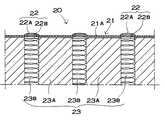
クッション電極20を、図5ないし図7に示す。図5は下側電極1Bの斜視図を、図6は下側電極1Bの拡大断面図を、図7は体側電極1Cの断面図をそれぞれ示している。クッション電極20は、これらの図に示すように、表面または全体を絶縁材とすと共に、可撓性を有する表面層21と、この表面層21に所定の間隔で配置している複数の局部電極22と、表面層21の裏面に配設されて、各々の局部電極22を弾性的に体表面に押圧する弾性押圧材23とを備える。
【0022】
図5に示す下側電極1Bは、6列に8個ずつ、全体で48個の局部電極22を配置している。これらの局部電極22は、等しい中心間隔(d)で配置されている。局部電極22の中心間隔(d)は、測定する領域の面積と、局部電極22の数、すなわち測定するポイント数によって決定される。図の下側電極1Bは、たとえば、中心間隔(d)を35mmとして、約500cm2の領域の心電位を測定できる。ただ、下側電極は、局部電極の数、すなわち測定ポイント数を20〜500とし、測定領域を150〜900cm2とし、中心間隔(d)を10〜60mmとすることができる。たとえば、下側電極は、局部電極の数を11×15の165個とし、局部電極の中心間隔を20mmとして、約600cm2の領域の心電位を測定できる。
【0023】
さらに、図3と図7に示す体側電極1Cは、2列に6個ずつ、全体で12個の局部電極22を配置している。これらの局部電極22も、等しい中心間隔(d)で配置されている。この体側電極1Cは、たとえば、中心間隔(d)を35mmとして、約80cm2の領域の心電位を測定できる。ただ、体側電極は、局部電極の数、すなわち測定ポイント数を4〜40とし、測定領域を3〜150cm2とし、中心間隔(d)を10〜60mmとすることができる。たとえば、体側電極は、局部電極の数を3×11の33個とし、局部電極の中心間隔を20mmとして、約100cm2の領域の心電位を測定できる。
【0024】
さらに、クッション電極は、配置される複数の局部電極の中心間隔(d)を、必ずしも全て等しくする必要はない。クッション電極は、局部電極の中心間隔を、患者の上下方向と左右方向とで変更することができ、あるいは、部分的に変更することもできる
【0025】
図5ないし図7に示すクッション電極20は、表面層21を可撓性シート21Aとしており、この可撓性シート21Aに複数の局部電極22を固定している。可撓性シート21Aは、自由に変形できる合成皮革である。合成皮革は、表面をプラスチック層でコーティングしているので汗が染み込まず、また表面に付着した汗等の汚れを簡単に払拭できる特長がある。ただ、可撓性シート21Aには、合成皮革でないプラスチックシートも使用できる。また、布地や不織布も使用できる。布地や不織布である可撓性シート21Aは、表面にコーティング剤や塗料を塗布して、汗等が染み込むのを防止すると共に、表面に付着した汗等の汚れを払拭することもできる。さらにまた、可撓性シート21Aは、プラスチックシート、布地、不織布等を積層したシートとすることができる。可撓性シート21Aには、患者の体表面の凹凸に沿って変形できる可撓性のある全てのシートが使用できる。さらに、可撓性シート21Aは、好ましくは伸縮性のあるシートを使用する。伸縮性のあるシートは、凹凸のある体表面に沿って変形できる特長がある。ただ、可撓性シート21Aは、多少の遊びがある状態で弾性押圧材23の表面に配設して、体表面の凹凸に沿って変形できる。可撓性シート21Aは、弾性押圧材23の表面とその周囲を被覆している。さらに、可撓性シート21Aは弾性押圧材23の裏面も被覆して、裏面で連結することができる。
【0026】
ただ、クッション電極は、必ずしも表面層を可撓性シートとする必要はない。表面層は、図示しないが、弾性押圧材であるプラスチック発泡体の表面に、コーティング剤や塗料や接着剤を塗布して設けることもできる。表面層を形成するコーティング剤、塗料、接着剤には、硬化した状態で可撓性を有するものを使用する。これらのコーティング剤、塗料、接着剤として、シリコン系、ウレタンゴム系のものが使用できる。さらに、クッション電極は、弾性押圧材であるプラスチック発泡体の表面に非発泡層を設けて、表面層とすることもできる。これらの表面層も、内部に汗等が染み込むのを防止して、表面に付着した汗等の汚れを簡単に払拭できる特長がある。
【0027】
局部電極22は金属製で、体表面に弾性的に押圧されて、体表面に誘導される心電位を検出する。局部電極22は、金属板をプレス加工して製作される。この局部電極22は、金属板の表面に金属メッキ層を設けている。金属メッキ層は、金メッキ、白金メッキ、銀メッキ、塩化銀メッキ、ニッケルメッキ、クロームメッキ、シンチュウメッキ、鉛メッキ等が使用できる。金メッキと白金メッキは、安定して体表面に電気的に接触できる特長がある。銀メッキと塩化銀メッキは、体表面に低抵抗な状態で安定して電気的に接触できる。ニッケルメッキとクロームメッキも安定して体表面に接触できる。シンチュウメッキと鉛メッキは表面が錆びるのを有効に防止できる。ただ、局部電極22は、ステンレス、シンチュウ、鉛、銀、塩化銀等の金属板で成形して表面に金属メッキ層を設けない構造とすることもできる。とくに、ステンレス、シンチュウ、鉛等の金属で成形される局部電極22は、錆びにくくできる特長がある。
【0028】
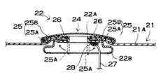
図8の拡大断面図に示す局部電極22は、金属板をプレス加工して体表面との接触面24を中央凸に湾曲させてなる接触電極22Aと、可撓性シート21Aの裏面に配設されてなる固定部22Bとからなる。接触電極22Aと固定部22Bは、可撓性シート21Aを挟着するように連結されて、局部電極22を可撓性シート21Aに固定している。
【0029】
接触電極22Aは、体表面に接触する接触面24を円形としている。接触面24の外径は、心電位を安定して検出するために大切である。小さ過ぎると体表面との接触面積が小さくなるので、安定して心電位を検出できなくなる。反対に大きすぎると、体表面の局部に誘導される心電位を正確に検出できなくなる。それは、大きな面積の電極が、体表面に誘導される心電位を短絡して同一電位にするからである。以上のことから、接触電極22Aの外径は、4〜20mm、好ましくは7〜15mm、さらに好ましくは8〜13mmとする。円形の接触電極22Aは、その中心を測定ポイントに位置させて、測定ポイント及びその周辺の心電位を安定して検出できる。ただ、接触電極は、必ずしも円形とする必要はなく、楕円形、長円形、多角形とすることもできる。多角形状である接触電極は、コーナー部分の角をとって湾曲させることにより、体表面に接触したときの感触をやわらげることができる。
【0030】
さらに、接触電極22Aは、図8に示すように、好ましくは接触面24を中央凸に湾曲させる。このように、接触面24が中央凸に湾曲している接触電極22Aは、体表面に対する角度が変わっても、体表面に常に広い面積で接触できる特長がある。ただ、接触面24は、曲率半径が小さ過ぎても、体表面に接触する面積は小さくなる。図の接触電極22Aは、接触面24の中央部で曲率半径を大きくして、周縁部分になるにしたがって曲率半径を小さくしている。接触電極22Aは、接触面24の中央部分の曲率半径を、10〜100mm、好ましくは12〜50mmとし、周縁部分の曲率半径を1〜20mmとしている。
【0031】
さらに、接触電極は、図示しないが、体表面に対して垂直ないしほぼ垂直に押圧できるならば、接触面を平面とすることもできる。この接触電極は、たとえば、接触面の面積を15〜300mm2、好ましくは30〜100mm2して、凹凸のある体表面に常に広い面積で接触させることができる。接触面が平面である接触電極も、好ましくは、周縁部分を1〜20mmの曲率半径で湾曲させて、体に接触させたときの感触をやわらげることができる。
【0032】
接触電極22Aは、可撓性シート21Aを貫通する連結凸部25を有する。この連結凸部25は、可撓性シート21Aを貫通して、可撓性シート21Aの内面で固定部22Bに連結される。図8の接触電極22Aは、連結凸部25を別の金属板で製作している。この連結凸部25は、筒部25Aの一端に鍔25Bを設けた形状である。接触電極22Aは、周縁部分を内側にかしめる状態で鍔25Bの周縁部分を挟着している。連結凸部25は、接触電極22Aのかしめられた周縁部分に鍔25Bの周縁部分が挟着されて、接触電極22Aに固定されている。
【0033】
固定部22Bは、連結凸部25を貫通する貫通孔26を中心に設けている。貫通孔26に挿通された連結凸部25は、図8の矢印で示すように筒部25Aの下端を拡開するように変形して、固定部22Bに抜けないように連結される。図8の固定部22Bは、接触電極22Aの外形にほぼ等しい外形としている。この固定部22Bは、局部電極22を可撓性シート21Aに抜けないように固定できる。この形状の固定部22Bは、金属板をプレス成形して製作され、あるいはプラスチックを成形して製作される。
【0034】
局部電極22にはリード線27が接続される。リード線27は、半田付けして、あるいはスポット溶接して局部電極22に接続される。リード線27は、接触電極22Aと固定部22Bのいずれかに接続される。各々の局部電極22に接続しているリード線27は、図6と図7に示すように、弾性押圧材23の内部に配線される。弾性押圧材23の内部に配線されるリード線27は、弾性押圧材23が変形しても無理な力が作用して断線することがないように、好ましくは、多少は弛む状態で配線する。このように、弾性押圧材23の内部にリード線27を配線するクッション電極20は、表面をすっきりとした外観にできると共に、測定時にリード線27が邪魔になることなく安定して測定できる特長がある。さらに、局部電極22とリード線27の接続部分は、図8に示すように、接着剤28に埋設している。この構造は、リード線27の接続部分の断線を有効に防止できる。局部電極22は、弾性押圧材23が変形する毎に変位する。このときリード線27の接続部分が変形すると断線しやすくなる。図8に示すように、接続部を接着剤28に埋設する構造は、局部電極22が移動しても接続部は変形せず、この部分の断線を有効に防止できる。
【0035】
弾性押圧材23は、弾性変形するプラスチック発泡体である。プラスチック発泡体は、連続気泡を有するように発泡成形された軟質のウレタンフォームが適している。ただ、プラスチック発泡体には、軟質ポリ塩化ビニル発泡体、ポリエチレン発泡体、エチレン酢酸ビニル発泡体等が使用できる。弾性押圧材23は、図6と図7に示すように、弾性係数の異なる複数の弾性変形プレート23Aを積層する構造とすることもできる。この弾性押圧材23は、局部電極22を固定する電極側には柔軟な弾性変形プレート23Aを積層して、局部電極22から離れた反対側には電極側の弾性変形プレート23Aよりも変形し難い弾性変形プレート23Aを積層する。この構造は、電極側の柔軟な弾性変形プレート23Aで局部電極22を体表面に押圧しながら、変形し難い弾性変形プレート23Aでしっかりと押圧できる。さらに、弾性押圧材は、図示しないが、内部に空気を充填している気密に閉塞された空気クッションとすることができる。空気クッションである弾性押圧材は、患者の体表面に沿って変形できる構造として、患者の荷重を均一に分散して押圧でき、全ての局部電極を理想的に体表面に押圧できる。
【0036】
弾性押圧材23は、厚さを110〜130mmとする板状である。ただ、弾性押圧材23は、その厚さを30〜200mm、好ましくは80〜150mmとすることができる。また、弾性押圧材23は、全体を均一な厚さとすることなく、上面を患者の体表面に沿って湾曲する形状とすることもできる。たとえば、人間の背中は、背骨に沿って多少は湾曲している。したがって、下側電極に配設される弾性押圧材は、背中に沿う形状に上面を湾曲させて、全ての局部電極を理想的に体表面に押圧できる。さらに、図示しないが、クッション電極を複数の領域に分割し、各領域に配設される弾性押圧材の厚さや形状を変更して、患者の体表面に沿わせることもできる。たとえば、下側電極を肩側と腰側の2つの領域に2分割し、肩側に配設される弾性押圧材を薄くして、腰側に配設される弾性押圧材を厚くすることもできる。
【0037】
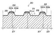
さらに、図9の弾性押圧材23は、局部電極22と対向する部分に突出部29を設けている。この弾性押圧材23は、突出部29で局部電極22を体表面に押圧する。このため、局部電極22が体表面にしっかりと押圧されて、安定して体表面の心電位を検出できる。
【0038】
さらに、図10の弾性押圧材23は、局部電極22に対向する押圧部分23aを、他の中間部分23bよりも変形し難くしている。言いかえると局部電極22に対向しない中間部分23bを局部電極22と対向する押圧部分23aよりも柔軟な弾性押圧材として変形しやすくしている。この弾性押圧材23は、押圧部分23aがしっかりと局部電極22を体表面に押圧するので、安定して心電位を検出できる。
【0039】
さらにまた、図11の弾性押圧材23は、弾性変形プレート23Aと押しスプリング23Bで構成している。弾性変形プレート23Aは、局部電極22と対向する部分に貫通孔や凹部を設けて、ここに押しスプリング23Bを配設している。押しスプリング23Bは、弾性変形する金属線をコイル状に巻いたコイルスプリングである。押しスプリング23Bは、その先端に局部電極22を接続してリード線に併用している。弾性変形プレート23Aは、押しスプリング23Bよりも柔軟に変形する。この弾性押圧材23は、押しスプリング23Bでもって局部電極22を体表面にしっかりと押圧できるので、局部電極22で心電位を安定して検出できる。また、押しスプリング23Bをリード線に併用するので、リード線の配線を簡単にできる。
【0040】
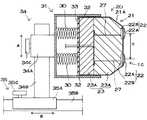
図7に示すクッション電極20の体側電極1Cは、押出スプリング30を介して固定ケース31に連結している。固定ケース31の周壁32と体側電極1Cとの間には数mmの隙間を設けて、体側電極1Cが固定ケース31からスムーズに出入りできるようにしている。体側電極1Cは、押出スプリング30で押圧される面に支持プレート33を固定している。この支持プレート33は、金属製あるいは硬質のプラスチック製の板材で、押出スプリング30で押圧されて体側電極1Cを体表面に向かって押し出す。この構造は、押出スプリング30で押し出される支持プレート33で体側電極1Cをしっかりと押圧しながら、弾性押圧材23で局部電極22を体表面に押圧できる。この図に示すクッション電極20は、弾性係数の異なる複数の弾性変形プレート23Aを積層した弾性押圧材23としている。ただ、クッション電極は、支持プレートと単層の弾性変形プレートで構成することもできる。このクッション電極は、たとえば、金属製あるいはプラスチック製の支持プレートの表面に柔軟な弾性変形プレートを積層して固定し、この弾性変形プレートで局部電極を体表面に押圧する。
【0041】
さらに、図示しないが、クッション電極を固定ケースに連結する押出スプリングには、好ましくは、スプリングの軸方向に向かってコイル径が変化しているタイプのコイルスプリングを使用する。このコイルスプリングとして、たとえば、円錐形、つづみ形、たる形のものが使用できる。これらの形状のコイルスプリングは、スプリングのストロークを確保できるので、クッション電極を固定ケースに沿ってスムーズに出入りできる特長がある。とくに、これらのコイルスプリングは、体側電極であるクッション電極を固定ケースに連結する押出スプリングに最適である。それは、押出スプリングで水平方向に押圧されるクッション電極が下方に垂れるのを有効に防止しながらストロークできるからである。
【0042】
固定ケース31は、昇降機構34に連結されており、上下位置を変更できるように配置されている。昇降機構34は、固定ケース31の底面に固定されて体側電極1Cの背面側に突出する支持アーム34Aと、垂直の姿勢で配設されて支持アーム34Aを貫通しているガイドロッド34Bと、支持アーム34Aにねじ込まれて、支持アーム34Aをガイドロッド34Bに固定する固定ネジ34Cとを備える。この昇降機構34は、固定ネジ34Cを緩めた状態で、図の矢印Aで示す支持アーム34Aの上下位置を調整し、固定ネジ34Cをねじ込んで支持アーム34Aを固定して体側電極1Cを最適な高さに固定する。
【0043】
さらに、昇降機構34は、図の矢印Bで示す左右方向の位置を調整できるように、スライド機構35に連結している。このスライド機構35は、ガイドロッド34Bの下端が固定されたスライド台35Aと、このスライド台35Aを矢印Bで示す方向にスライドさせるガイドレール35Bと、スライド台35Aにねじ込まれて、スライド台35Aをガイドレール35Bに固定する固定ネジ35Cとを備える。このスライド機構35は、固定ネジ35Cを緩めた状態でスライド台35Aを矢印Bで示す方向にスライドさせて体側電極1Cと患者の体側との距離を調整し、固定ネジ35Cをねじ込んでスライド台35Aを固定して体側電極1Cの左右位置を固定する。したがって、体側電極1Cは、昇降機構34で上下位置が、スライド機構35で左右位置が調整されて、患者の体側の最適な位置に配置される。
【0044】
さらに、図3と図7に示す体側電極1Cは、局部電極22を配置してなる体表面に対向する面の周縁部である4辺をカットして面取りしている。この構造の体側電極1Cは、局部電極22を体表面側に突出させる状態に配置できるので、局部電極22を確実に体表面に接触できる特長がある。ただ、体側電極も、図9に示す下側電極と同様に、局部電極と対向する部分に突出部を設けて、この突出部で局部電極を体表面に押圧することもできる。さらに、体側電極は、図10と図11に示す構造で局部電極に対向する押圧部分を、他の部分よりも変形し難くして、この押圧部分で局部電極をしっかりと体表面に押圧することもできる。
【0045】
さらに、下側電極1Bも図12に示すように、押出スプリング30を介して固定ケース31に装着することができる。この下側電極1Bも、固定ケース31の周壁32との間に隙間を設けて、スムーズに出入りできるようにしている。この押出スプリング30にも、スプリングの軸方向に向かってコイル径が変化している円錐形、つづみ形、たる形のコイルスプリングが使用できる。ただ、クッション電極は、押出スプリングを介することなく、直接に固定することもできる。
【0046】
さらに、図5に示す下側電極1Bは、クッション電極20の正確な位置に患者を寝かせることができるように、位置決ライン36を表示している。図に示すクッション電極20は、左右対称の位置にそれぞれ4本の位置決ライン36を互いに平行に表示している。これらの位置決ライン36は、患者が正しい測定位置についたときの肩や乳首や肋骨等の位置を表示しており、この位置決ライン36を基準にして患者を正確な位置に寝かせることができるようにしている。図に示す下側電極1Bは、たとえば、中央の2本の位置決ライン36の間に患者の乳首が位置するように患者の上下位置を決めて、下側電極1Bを所定の位置に配設できるようにしている。このように、位置決ライン36を備えるクッション電極20は、常に患者を正確な位置に寝かせることができる。さらに、図示しないが、下側電極は、左右の位置を特定する位置決ラインを表示することもできる。さらに、クッション電極は、位置決ラインに代わって、患者の上下や左右の位置を特定できる点やマークを表示することもできる。
【0047】
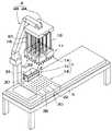
ロッド電極10である上側電極1Aは、図3、図4、図13及び図14に示すように、複数の電極ユニット11で構成している。これらの図に示すロッド電極10は、8個の電極ユニット11を備える。8個の電極ユニット11は、2列に4個ずつ配置している。各々の電極ユニット11は、図13の正面図と図14の底面図に示すように、紐状のゴム状弾性体である可動性部材15でもって連結されている。このように、複数の電極ユニット11で構成されるロッド電極10は、各電極ユニット11の姿勢を個々に変化できる構造として、理想的に複数の導電ロッド12を患者の胸に接触できる。それは、各電極ユニット11の下面を患者の胸面に沿う姿勢で配置できるからである。
【0048】
さらに、図13と図14に示すロッド電極10は、各列の電極ユニット11の下面に弾性変形プレート16を固定して、この弾性変形プレート16で4個の電極ユニット11を連結している。弾性変形プレート16は、曲げ方向に弾性を有する板材やシート材、たとえばゴム板や合成樹脂プレート等である。この弾性変形プレート16は、互いに隣接する電極ユニット11の間隔を所定の間隔に保持しながら各電極ユニット11の姿勢を患者の胸面に沿う状態に配置できる特長がある。さらに、この弾性変形プレート16は、左右の両側に位置する電極ユニット11を、図13の矢印で示す方向に傾斜させた状態において、両側の電極ユニット11が転倒するのを防止するはたらきもある。
【0049】
それぞれの電極ユニット11は、図15と図16に示すように、患者の体表面の複数ヶ所に押圧される複数本の導電ロッド12と、これらの導電ロッド12を出入りできるように装着している電極本体13と、この電極本体13から導電ロッド12を弾性的に押し出す弾性押出材14とを備える。
【0050】
図に示す電極ユニット11は、8本の導電ロッド12を備える。8本の導電ロッド12は、底面の形状を長方形とする電極ユニット11に、2列に4個ずつ配置している。これらの導電ロッド12は、等しい中心間隔(d)で配置されている。導電ロッド12の中心間隔(d)は、下側電極1Bや体側電極1Cの局部電極22の中心間隔(d)と等しくすることができる。ただ、上側電極1Aの導電ロッド12の中心間隔(d)は、種々に変更することもできる。導電ロッド12の中心間隔(d)は、測定する領域の面積と、導電ロッド12の本数、すなわち測定するポイント数によって決定される。図に示すロッド電極10は、8個の電極ユニット11に各8本の導電ロッド12を配設しているので、全体では64本の導電ロッド12を備えている。
【0051】
複数本の導電ロッド12は、電極本体13から体表面に向かって弾性的に突出しており、患者の体表面を独立して押圧する。これらの導電ロッド12は、電極本体13に出入りできるように連結しているロッド部12Bと、このロッド部12Bの先端部に連結されて体表面に接触して体表面に誘導される心電位を検出する接触電極12Aとを備える。図の導電ロッド12は、ロッド部12Bを金属ロッドとしている。ロッド部12Bは、直径を1.5〜6mm、好ましくは3〜4mmとする金属線である。ロッド部12Bは、細すぎると曲がりやすく、太すぎると摺動抵抗が大きくなってスムーズに出入りさせるのが難しくなる。ロッド部12Bは、SUS304等のステンレス線、表面をメッキしているピアノ線等の曲がり難い金属線が適している。さらに、ロッド部は、円筒状として軽くすることもできる。ただし、ロッド部は、必ずしも金属製のロッドとする必要はなく、たとえば、硬質プラスチックロッドの表面や内面に導電膜をコーティングしたもの、あるいは導電性のあるカーボン繊維をロッド状に成形したものも使用できる。ロッド部12Bは、軸方向に移動できるように電極本体13に装着されて、弾性押出材14で体表面に向かって押圧される。
【0052】
接触電極12Aは金属製で、体表面に弾性的に押圧されて、体表面に誘導される心電位を検出する。接触電極12Aは、金属を切削加工し、あるいは鋳造し、あるいはまたプレス加工して製作される。金属製の接触電極12Aは、たとえば、ステンレス、シンチュウ、鉛、銀、塩化銀等の金属で成形することができる。とくに、ステンレス、シンチュウ、鉛等の金属で成形される接触電極12Aは、錆びにくくできる特長がある。さらに、金属製の接触電極12Aは、安定して心電位を検出するために、接触面12aの表面、あるいは全面に金属メッキ層を設けることができる。金属メッキ層は、金メッキ、白金メッキ、銀メッキ、塩化銀メッキ、ニッケルメッキ、クロームメッキ、シンチュウメッキ、鉛メッキ等が使用できる。金メッキと白金メッキは、安定して体表面に電気的に接触できる特長がある。銀メッキと塩化銀メッキは、体表面に低抵抗な状態で安定して電気的に接触できる。ニッケルメッキとクロームメッキも安定して体表面に接触できる。シンチュウメッキと鉛メッキは表面が錆びるのを有効に防止できる。
【0053】
接触電極12Aの接触面12aの大きさと形状は、心電位を安定して検出するために大切である。接触電極12Aは、体表面に接触する接触面12aを、ロッド部12Bの横断面よりも大きい外形の円形としている。接触面12aの外径は、小さ過ぎると体表面との接触面積が小さくなるので、安定して心電位を検出できなくなる。反対に大きすぎると、体表面の局部に誘導される心電位を正確に検出できなくなる。それは、大きな面積の電極が、体表面に誘導される心電位を短絡して同一電位にするからである。以上のことから、接触電極12Aの外径は、5〜20mm、好ましくは7〜15mm、さらに好ましくは8〜13mmとし、ロッド部12Bの直径の2〜15倍、好ましくは、3〜8倍とする。円形の接触電極12Aは、その中心を測定ポイントに位置させて、測定ポイント及びその周辺の心電位を安定して検出できる。ただ、接触電極は、必ずしも円形とする必要はなく、楕円形、長円形、多角形とすることもできる。多角形状である接触電極は、コーナー部分の角をとって湾曲させることにより、体表面に接触したときの感触をやわらげることができる。
【0054】
さらに、接触電極12Aは、体表面との接触面12aを中央凸に湾曲する湾曲面としている。このように、接触面12aが中央凸に湾曲している接触電極12Aは、体表面に対する角度が変わっても、体表面に常に広い面積で接触できる特長がある。ただ、接触面12aは、曲率半径が小さ過ぎても、体表面に接触する面積は小さくなる。図の接触電極12Aは、接触面12aの中央部で曲率半径を大きくして、周縁部分になるにしたがって曲率半径を小さくしている。接触電極12Aは、接触面12aの中央部分の曲率半径を、10〜100mm、好ましくは12〜50mmとし、周縁部分の曲率半径を1〜20mmとしている。
【0055】
さらに、接触電極12Aの接触面12aの曲率半径は、体表面に押圧される部位によって変更することができる。たとえば、接触面の曲率半径を大きくすると、体表面との接触面積が大きくなって安定して心電位を検出できるが、この形状は体表面に押圧されて滑りやすくなる。上側電極は、患者の体側に近い部分に押圧される電極が滑りやすくなる傾向がある。体側が垂直に近い面となるからである。この弊害を避けるために、たとえば、体側に近い電極に装着する接触電極は、患者の胸の中央部分に接触する接触電極よりも、接触面の曲率半径を小さくして滑り難くすることができる。胸の中央部分の接触電極は、接触面の曲率半径を大きくして、安定して心電位を検出できるようにする。とくに、心電位は胸の中央部分で高い電圧となるので、この部分の電圧を正確に検出することが大切である。したがって、胸の中央部分に押圧される接触電極は、接触面の中央部分の曲率半径を大きくし、体側に近い部分に押圧される接触電極は中央部分の曲率半径を小さくして、滑り難くすることができる。
【0056】
接触電極12Aは、脱着できるようにロッド部12Bに連結することができる。図16の接触電極12Aは、簡単に脱着できるように、ロッド部12Bを挿入する連結孔12bを設けており、この連結孔12bにロッド部12Bの先端部を入れて脱着できるように連結している。図16の接触電極12Aは、止ネジ17を介してロッド部12Bに脱着できるように連結している。この接触電極12Aは止ネジ17をねじ込む雌ネジ孔12cを半径方向に設けている。この接触電極12Aは、止ネジ17を緩めてロッド部12Bから取り外し、止ネジ17を締めてロッド部12Bに固定される。このように、脱着できる接触電極12Aは、表面が汚れ、あるいは接触面12aの金属が酸化して変質し、あるいは表面に病原菌等が付着して不衛生になると、接触電極12Aを新しいものに交換できる特長がある。ただ、接触電極12Aは、必ずしも脱着できるようにロッド部12Bに連結する必要はなく、半田付けや溶着等によって外れないように固定することもできる。
【0057】
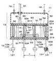
電極本体13は、図16において、下方を開口している箱形のケース50と、2枚の絶縁性の板材51とを備えている。2枚の板材51には、これを貫通して導電ロッド12のロッド部12Bを出入自在に挿通している。2枚の板材51は、互いに平行に配設されており、対向する位置に挿通孔51Aを開口して、これらの挿通孔51Aに導電ロッド12のロッド部12Bを挿通している。2枚の板材51は、間に配設された複数本の支柱52に固定されて所定の間隔に保持されている。ロッド部12Bは、その中間部分であって、2枚の板材51の間に位置して固定リング55を固定している。固定リング55は、挿通孔51Aよりも大きな外形を有し、挿通孔51Aの周縁部に当接して、導電ロッド12が電極本体13から抜けるのを阻止すると同時に、導電ロッド12の突出量を特定している。
【0058】
さらに、2枚の板材51には、電極本体13に出入りするロッド部12Bの摺動抵抗を小さくするために、ガイドプレート53を配設している。図16に示す電極本体13は、下方に位置する板材51の下面と、上方に位置する板材51の上面とにガイドプレート53を積層して固定している。ガイドプレート53は、導電ロッド12を貫通させるためのガイド孔53Aを開口しており、このガイド孔53Aに導電ロッド12を挿入している。ガイドプレート53のガイド孔53Aは、板材51に開口した挿通孔51Aに対向する位置に開口している。ガイド孔53Aは、挿通孔51Aの中央に位置して、挿通孔51Aよりも小さく開口しており、ロッド部12Bが挿通孔51Aの内面に接触することなく往復運動できるようにしている。ガイドプレート53には、ガイド孔53Aを摺動するロッド部12Bの摺動抵抗を小さくする材質のもの、たとえば、テフロン(登録商標)樹脂が使用できる。このように、摺動抵抗の小さなガイドプレート53のガイド孔53Aに沿って導電ロッド12を摺動させる構造は、電極本体13に出入りする導電ロッド12の摺動抵抗を小さくでき、導電ロッドを滑らかに往復運動できる。
【0059】
さらに、図16の電極本体13は、電極ユニット11を安定して胸面に配置するために、下方の板材51に重り56を固定している。この重り56は金属プレートで、鉛板や鉄板等が使用できる。金属プレートである重り56は、積層枚数を変更して重さを簡単に調整できる。このように、電極本体13の下部に重り56を固定する構造は、電極本体13の重心の位置を低くできるので、電極ユニット11を胸面に載置する状態で、電極ユニット11の姿勢を安定して保持できる特長がある。さらに、重り56を備える電極本体13は、導電ロッド12を安定して体表面に押圧できる特長もある。
【0060】
弾性押圧材14は、ロッド部12Bに挿通しているコイルスプリングで、2枚の板材51の間に配設している。このコイルスプリングは押バネで、下端を導電ロッド12の中間に、上端を上方の板材51にプリント印刷された銅膜等の導電層54に接続している。このコイルスプリングは、導電ロッド12を電極本体13から弾性的に押し出して、接触電極12Aを体表面に押圧する。ただ、コイルスプリングである弾性押圧材は、引張バネとすることもできる。引張バネである弾性押圧材は、図示しないが、上側の板材の上方で導電ロッドに挿通して、導電ロッドの上端に連結することもできる。この弾性押圧材は、上端を板材の上面から突出する導電ロッドの先端に、下端を板材にプリント印刷された銅膜等の導電層に接続する。
【0061】
コイルスプリングである弾性押圧材14は、導電ロッド12を導電層54に電気接続するリード線に併用している。コイルスプリングである弾性押圧材14は、バネ鋼鋼材、ピアノ線、ステンレス線、黄銅線、洋白線、りん青銅線、ベリリウム銅線等で製作される。とくに、銅を多く含有する線材で製造されたコイルスプリングは、導電性に優れているので、リード線に併用するコイルスプリングに適している。さらに、図に示す導電ロッド12は、コイルスプリングに加えて、リード線57によっても板材51の導電層54に接続している。ただ、導電ロッドは、コイルスプリングとリード線のどちらか一方を介して導電層に接続することもできる。
【0062】
図16に示す導電ロッド12は、コイルスプリングである弾性押圧材14の下端とリード線57の下端を、ロッド部12Bの中間に固定された固定リング55に半田付けして接続している。ただ、コイルスプリングとリード線57の下端は、図17に示すように、連結筒58を介して導電ロッド12に連結することもできる。この連結筒58は、中心に導電ロッド12を挿通できる貫通孔58Aを開口しており、上面にコイルスプリングとリード線57の下端を半田付け等によって固定している。この連結筒58は、貫通孔58Aにロッド部12Bを挿入する状態で、止ネジ59がねじ込まれて導電ロッド12に連結される。このように、連結筒58を介して弾性押圧材14であるコイルスプリングやリード線57を導電ロッド12に連結する構造は、導電ロッド12を脱着自在に連結して、導電ロッド12を交換できる特長がある。
【0063】
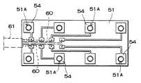
図18は、上方の板材51の底面図を示す。この図に示す板材51は、銅膜等の導電層54をプリント印刷している。この導電層54は、引出線60を接続している。導電ロッド12に接続された引出線60は、図8に示すように1本のリード線61に集合されて、リード線61でもって演算回路2に接続される。
【0064】
複数の電極ユニット11で構成される上側電極1Aは、図3と図4に示すように、吊下機構4で吊り下げられて、患者の胸の所定の位置に配置される。これらの図に示す吊下機構4は、複数の電極ユニット11を水平の姿勢で吊り下げる上下台4Aと、この上下台4Aを水平の姿勢で上下、左右に移動させる支持台4Bとを備える。複数の電極ユニット11は、吊り紐18を介して上下台4Aから吊り下げられている。この上側電極1Aは、この上下台4Aを水平の姿勢で移動させて、複数の電極ユニット11からなるロッド電極10を所定の位置に配置する。患者の胸面に配置された上側電極1Aは、その自重により所定の位置に保持される。
【0065】
さらに、上側電極1Aは、図4と図13の鎖線で示すように、装着バンド40を介して複数の電極ユニット11からなるロッド電極10を患者にしっかりと装着することもできる。図13に示すロッド電極10は、各列の最も外側に位置する電極ユニット11に、伸縮性の装着バンド40を連結している。装着バンド40は、先端に連結具41を設けており、この連結具41を介して先端部をベッド3あるいは体側電極1Bの固定ケース31に連結できるようにしている。連結具41には、たとえば、フック等の引掛具が使用できる。この上側電極1Aは、図の鎖線で示すように、装着バンド40の先端の連結具41をベッド3の側縁あるいは体側電極1Bの固定ケース31に連結して患者に装着される。図13に示す装着バンド40は、図において左右の先端に連結具41としてフックを設けている。ただ、装着バンドは、端部を筒状に連結してこの筒部に連結ロッドを挿入し、この連結ロッドをベッド等に設けたフック等の引掛部に引っかけて連結することもできる。さらに、連結具には、必ずしもフックやロッドを使用することなく、面ファスナーやホック等も使用できる。この装着バンドは、一端をベッドや体側電極の固定ケースに固定した第1装着バンドと、上側電極の各列の最も外側に位置する電極ユニットに連結された第2装着バンドで構成し、各々の装着バンドを面ファスナーやホック等で連結する構造とすることもできる。この装着バンドは、互いの連結位置を変更して長さを調整できるので、上側電極を最適な押圧力で装着できる特長がある。さらに、フック等の連結具で装着される装着バンドも、中間で分割してこの分割部分を面ファスナーやホック等の連結部材で連結する構造として、長さを調整することができる。
【0066】
以上のロッド電極10は、複数の電極ユニット11で構成しているが、ロッド電極は、単一の電極本体から複数本の導電ロッドを突出させる構造とすることもできる。このロッド電極は、電極本体の下面を患者の胸面に沿う形状とすることができる。さらに、左右の両側部に配設される導電ロッドを、水平面に対して多少傾斜する姿勢で配置することもできる。
【0067】
図4に、電極1を患者に装着した状態を示す。この電極1は、下側電極1Bの上に患者が載り、体側電極1Cを患者の脇下の体側に押圧し、上側電極1Aを患者の上面の心臓に近い体表面に載置して、患者の背中と体側と胸とに配置される。クッション電極20である下側電極1Bは、この上に患者が載ると、弾性押圧材23が各々の局部電極22を体表面に弾性的に押圧して、局部電極22でもって心電位を検出して、検出した心電位を演算回路に出力する。クッション電極20である体側電極1Cも、弾性押圧材23が各々の局部電極22を体表面に弾性的に押圧する。ロッド電極10である上側電極1Aは、弾性押出材14が導電ロッド12を弾性的に押し出して接触電極12Aを体表面に押圧し、接触電極12Aでもって心電位を検出して、検出した心電位を演算回路に出力する。
【0068】
本発明の体表面心電計は、図2に示すように、演算表示部2が電極1に誘導される心電圧を演算して体表面に誘導される体表面電位分布図を表示する。演算表示部2は、電極1に誘導される心電位から体表面に誘導される体表面電位分布図を演算する演算回路2Aと、この演算回路2Aで演算された体表面電位分布図を表示する外部出力装置2Bと、演算回路2Aに接続している操作スイッチ2Cとを備える。図において、外部出力装置2Bには、モニタテレビ2aとプリンター2bを使用している。
【0069】
演算回路2Aは、電極1から送られてくる電気信号を決められた方式に従って演算処理する。電極1は、体表面の複数ヶ所に誘導される心電位を検出し、検出した信号を演算回路2Aに送る。電位の測定は、所定の時間毎に行われ、測定する時間間隔は使用者が操作スイッチ2Cから演算回路2Aに入力する。したがって、演算回路2Aからの指令に基づき、電極1は各点の電位を測定し、電圧値をデータとして演算回路2Aに出力する。演算回路2Aは、一定時間おきに各電極1の測定電位から等電位点を演算し、これから等電位線の位置を算出する。得られた出力信号は外部出力装置2Bに送られ、外部出力装置2Bで等電位線を描き体表面の電位分布図を作成する。
【0070】
演算回路2Aは、入力された電位信号を演算し、等電位点を算出して等電位線を決定できるすべての装置が使用できる。演算回路2Aには、これらの処理を可能にするようカスタマイズされたICや電算機の他、汎用的なMPUやCPUを使用したコンピュータ、いわゆるマイクロコンピュータやパーソナル・コンピュータ、ワークステーション等が使用できる。
【0071】
さらに演算回路2Aは、電極1から送られてきた心電位の値を各時間毎に保持、記憶する記憶媒体を有する(図示せず)。記憶媒体には、ランダム・アクセス・メモリ(RAM)、レジスタ等の記憶素子や、ハードディスク等の固定記憶装置、光磁気ディスク、CD−R、DVD、フレキシブルディスク等の記憶媒体が使用できる。ただ、処理速度の向上を図るためには、アクセス速度の速いメモリ素子を使用することが好ましい。記憶媒体に記憶されたデータ、若しくは電極1から送られてきた電圧値に基づき、演算回路2Aは等電位点を算出し、等電位線を描くための線データを演算する。演算されたデータは外部出力装置2Bに送られる。
【0072】
外部出力装置2Bは、与えられた等電位線のデータに基づき、体表面電位分布図を表示する。外部出力装置2Bには、モニタテレビやプリンター、プロッタ等が複数使用できる。図において、外部出力装置2Bには、モニタテレビ2aとプリンター2bを使用している。使用者は、モニタテレビ2aを使用して体表面電位分布図を随時観測でき、一方でプリンター2bで所定の時間おきに電位分布図を印刷したり、あるいは所望の時間での電位分布図を印刷することができる。
【0073】
記憶媒体に保持されるデータは、体表面の各電位である必要はない。任意の時間における体表面電位分布図を記憶することもできる。例えば、演算回路2Aで演算された等電位線のデータを保持して、このデータを呼び出すことで各時間毎の体表面電位分布図を切り替えて表示することもできる。特に、演算前のデータでなく、演算後のデータを記憶しておくことは、演算に要する時間を省略できるので、外部出力装置に表示されるまでに要する時間を短縮し、より高速に体表面電位分布図を表示することができる。ただ、各点の電位値と等電位線の両方のデータを記憶することも、また演算回路2Aで演算途中のデータを保持しておくこともできるのはいうまでもない。
【0074】
体表面電位分布図の表示は、心電位をサンプリングする間隔や各時点での電位分布の表示を切り替える時間等を調整することによって精度を向上できる。より高速かつ詳細に表示するには、処理能力の高い高速なコンピュータや、画面表示用のチップ、RAM等を備えるいわゆるグラフィックアクセラレータ等を使用した描画が高速なコンピュータ等を、演算回路2Aに使用することで改善できる。
【0075】
【発明の効果】
本発明の体表面心電計は、体表面の多数の部位から正確に安定して心電位を検出できることに加えて、電極を極めて簡単な構造として安価に多量生産できる特長がある。それは、本発明の体表面心電計の電極が、表面層に所定の間隔で複数の局部電極を配置し、この表面層の裏面に弾性押圧材を配設する簡単な構造とするからである。この電極は、各々の局部電極を弾性押圧材でもって弾性的に体表面に押圧して心電位を検出する。したがって、この電極で患者の体表面を押圧すると、弾性押圧材が押し潰され、押し潰された弾性押圧材が各々の局部電極を体表面に押圧する。
【0076】
さらに、本発明の体表面心電計は、快適な環境で正確に心電位を検出できる特長もある。それは、表面層に複数の局部電極を設け、表面層の裏面に設けている弾性押圧材で体表面に押圧するからである。この構造の電極は、体表面を表面層で被覆する状態で心電位を検出するので、表面層が体表面の乾燥を防止する。このため、表面層に配置している局部電極は、低い接触抵抗で体表面に接触して、正確に心電位を検出する。したがって、極めて高い精度で体表面電位分布図を作成することができる。
【図面の簡単な説明】
【図1】心臓付近の体表面の電位分布図
【図2】本発明の一実施例にかかる体表面心電計のブロック線図
【図3】本発明の一実施例にかかる体表面心電計の概略斜視図
【図4】図3に示す体表面心電計の使用状態を示す概略横断面図
【図5】図3に示す体表面心電計の下側電極であるクッション電極の斜視図
【図6】図5に示す下側電極の拡大断面図
【図7】図3に示す体表面心電計の体側電極であるクッション電極の垂直断面図
【図8】局部電極の拡大断面図
【図9】クッション電極の他の一例を示す拡大断面図
【図10】クッション電極の他の一例を示す拡大断面図
【図11】クッション電極の他の一例を示す拡大断面図
【図12】下側電極の他の一例を示す断面図
【図13】図3に示す体表面心電計の上側電極であるロッド電極の正面図
【図14】図13に示すロッド電極の底面図
【図15】ロッド電極の電極ユニットの斜視図
【図16】図15に示す電極ユニットの断面図
【図17】導電ロッドをコイルスプリング及びリード線に接続する一例を示す拡大断面図
【図18】図16に示す電極ユニットの上方の板材の底面図
【符号の説明】
1…電極 1A…上側電極 1B…下側電極
1C…体側電極
2…演算表示部 2A…演算回路 2B…外部出力装置
2C…操作スイッチ
2a…モニタテレビ 2b…プリンター
3…ベッド
4…吊下機構 4A…上下台 4B…支持台
10…ロッド電極
11…電極ユニット
12…導電ロッド 12A…接触電極 12B…ロッド部
12a…接触面 12b…連結孔
12c…雌ネジ孔
13…電極本体
14…弾性押出材
15…可動性部材
16…弾性変形プレート
17…止ネジ
18…吊り紐
20…クッション電極
21…表面層 21A…可撓性シート
22…局部電極 22A…接触電極 22B…固定部
23…弾性押圧材 23A…弾性変形プレート
23B…押しスプリング
23a…押圧部分 23b…中間部分
24…接触面
25…連結凸部 25A…筒部 25B…鍔
26…貫通孔
27…リード線
28…接着剤
29…突出部
30…押出スプリング
31…固定ケース
32…周壁
33…支持プレート
34…昇降機構 34A…支持アーム 34B…ガイドロッド
34C…固定ネジ
35…スライド機構 35A…スライド台 35B…ガイドレール
35C…固定ネジ
36…位置決ライン
40…装着バンド
41…連結具
50…ケース
51…板材 51A…挿通孔
52…支柱
53…ガイドプレート 53A…ガイド孔
54…導電層
55…固定リング
56…重り
57…リード線
58…連結筒 58A…貫通孔
59…止ネジ
60…引出線
61…リード線[0001]
TECHNICAL FIELD OF THE INVENTION
The present invention measures the cardiac potential from many points on the body surface close to the heart in order to clearly understand the cardiac electrical phenomenon, and calculates the measured cardiac potential to display a body surface potential diagram at a certain time. Related to electric meter.
[0002]
[Prior art]
The body surface electrocardiograph is provided with a plurality of electrodes at 100 to 500 points on the body surface close to the heart, and simultaneously collects cardiac potentials from all the electrodes. A body surface potential distribution map for determining an electric phenomenon is created.
[0003]
The body surface electrocardiograph creates a body surface potential distribution diagram which is a potential distribution diagram appearing on the body surface near the heart at a certain time, for example, as shown in FIG. The potential distribution diagram is a distribution diagram of the potential on the body surface in the cardiac electrical phenomenon. The potential distribution map is calculated by a computer based on measurement signals from all the electrodes. That is, the measured potential of each electrode at a certain time is stored in the memory of the computer, the equipotential lines are calculated based on the measured potential of each electrode, and the equipotential lines are monitored, for example, every tens of microvolt pitch. It is displayed on a television or a printer.
[0004]
The body surface electrocardiograph having this structure can inspect the electrical phenomena of the heart more precisely than a conventional electrocardiograph. However, since the body surface electrocardiograph detects the cardiac potential from a large number of electrodes, it is extremely difficult to accurately and stably detect the cardiac potential from all the electrodes. This is because it is difficult to bring all the electrodes into contact with the body surface in an electrically low-resistance state. When the contact resistance between the electrode and the body surface increases, the large contact resistance causes a decrease in the cardiac potential detected by the electrode. Furthermore, when the electrode is brought into contact with the body surface, a local battery is generated between the body surface and the electrode, and the voltage of this local battery is several hundred mV, which is extremely large compared to the cardiac potential. Makes detection difficult. Since the local battery generates a DC voltage, it can be distinguished from a changing cardiac potential unless it changes. However, since the voltage of the local battery is extremely large, several tens to hundred times as large as the cardiac potential, a slight change in the voltage makes accurate detection of the cardiac potential difficult. This is because a change in the voltage of the local battery and a change in the cardiac potential cannot be distinguished.
[0005]
In order to avoid such adverse effects, a conventional body surface electrocardiograph uses disposable electrodes that adhere to the body surface via a conductive paste. Since this electrode is adhered to the body surface via the conductive paste, the electrode can be brought into contact with the body surface in a state of low resistance as long as it can be properly adhered. However, it is actually quite difficult to adhere all the electrodes consisting of 100 or more to the body surface so as not to peel off, and there is a disadvantage that if any electrode is peeled off from the body surface, the cardiac potential cannot be detected accurately. . Further, since all the electrodes of 100 or more are disposable, there is a disadvantage that the running cost of the electrocardiographic measurement of one patient becomes extremely high.
[0006]
For the purpose of solving such a drawback, an electrode for independently pressing a large number of metal rods against the body surface has been developed (see Patent Document 1). This electrode presses each metal rod independently against the body surface, so that the cardiac potential induced on the body surface can be accurately detected. In particular, a cardiac potential can be detected without using a conductive paste. When the metal rod is continuously pressed against the body surface, a conductive liquid such as sweat is interposed between the metal rod and the body surface, and the contact resistance between the body surface and the metal rod is increased. Is smaller.
[0007]
[Patent Document 1]
Japanese Patent Publication No. 2-9811
[0008]
[Problems to be solved by the invention]
Electrodes having this structure are suitable for detecting cardiac potentials from a large number of sites on the body surface, but have the disadvantage that the structure is complicated and the manufacturing cost is high. Another drawback is that it is difficult to attach the electrode to the patient's body so that the electrode spacing is accurate. This is because the metal rods are mounted so as to be able to enter and exit a plurality of cases in order to press each electrode independently against the body surface. Adjacent cases are connected by a string, but if the inclination angle of the case is different, the distance between the electrodes attached to the adjacent case changes, and it is attached to the patient's body surface while accurately specifying the electrode interval There are drawbacks that make it difficult to do.
[0009]
Further, in an electrode for detecting a cardiac potential by pressing a metal rod against a body surface, temperature and humidity at the time of measurement affect the measurement. Unfortunately, a comfortable environment for the patient is not always a comfortable environment for accurately detecting cardiac potential from multiple electrodes. The environment where the cardiac potential can be accurately detected by the metal rod is an environment with high temperature and high humidity. This is because, in this environment, the body surface of the patient is moistened with sweat, and the electrical contact resistance between the metal rod and the body surface is reduced and stabilized. This environment can be realized in the summer without cooling, but in reality such an environment rarely detects a cardiac potential. Cooling in summer or heating in winter reduces indoor humidity. When the humidity decreases, the skin becomes dry, the contact resistance between the metal rod and the body surface increases, and it becomes difficult to accurately detect the cardiac potential.
[0010]
The present invention has been developed for the purpose of solving such a drawback. An important object of the present invention is to provide a body surface electrocardiograph capable of accurately and stably detecting cardiac potential from a large number of sites on the body surface, and having a very simple structure and capable of mass production at low cost.
Another important object of the present invention is to provide a body surface electrocardiograph capable of accurately detecting a cardiac potential and creating a highly accurate body surface potential distribution map even in a comfortable indoor environment. .
[0011]
[Means for Solving the Problems]
The body surface electrocardiograph according to the present invention includes an
[0012]
In the body surface electrocardiograph of the present invention, the
[0013]
The
[0014]
In the
[0015]
The elastic pressing
[0016]
BEST MODE FOR CARRYING OUT THE INVENTION
Hereinafter, embodiments of the present invention will be described with reference to the drawings. However, the embodiments described below exemplify a body surface electrocardiograph for embodying the technical idea of the present invention, and the present invention does not specify the body surface electrocardiograph as follows.
[0017]
Further, in this specification, in order to make it easy to understand the claims, the numbers corresponding to the members shown in the embodiments are referred to as "claims" and "means for solving the problem". Are added to the members indicated by "." However, the members described in the claims are not limited to the members of the embodiments.
[0018]
2 to 4 show a body surface electrocardiograph according to an embodiment of the present invention. The body surface electrocardiograph shown in these figures is provided with an
[0019]
As shown in FIGS. 3 and 4, the
[0020]
In the body surface electrocardiograph of FIG. 3, the
[0021]
The
[0022]
As for the
[0023]
Further, the body-
[0024]
Furthermore, in the cushion electrode, it is not always necessary to make all the center intervals (d) of the plurality of local electrodes arranged equal. The cushion electrode can change the center interval between the local electrodes in the vertical direction and the horizontal direction of the patient, or can be partially changed.
[0025]
In the
[0026]
However, the surface layer of the cushion electrode does not necessarily need to be a flexible sheet. Although not shown, the surface layer may be provided by applying a coating agent, a paint, or an adhesive to the surface of a plastic foam as an elastic pressing material. As the coating agent, paint, and adhesive for forming the surface layer, those having flexibility in a cured state are used. As these coating agents, paints and adhesives, silicone-based and urethane rubber-based ones can be used. Further, the cushion electrode may be provided as a surface layer by providing a non-foamed layer on the surface of a plastic foam which is an elastic pressing material. These surface layers also have the feature that they prevent permeation of perspiration and the like into the inside, and can easily wipe off dirt such as perspiration attached to the surface.
[0027]
The
[0028]
The
[0029]
The
[0030]
Furthermore, as shown in FIG. 8, the
[0031]
Further, although not shown, the contact surface may be a flat surface if it can be pressed perpendicularly or almost perpendicularly to the body surface. This contact electrode has, for example, a contact surface area of 15 to 300 mm.2 , Preferably 30-100 mm2 As a result, it is possible to always bring a large area into contact with the uneven body surface. The contact electrode having a flat contact surface also preferably has a peripheral portion that is curved with a radius of curvature of 1 to 20 mm, so that the feel when contacting the body can be softened.
[0032]
The
[0033]
The fixing
[0034]
A
[0035]
The elastic pressing
[0036]
The elastic pressing
[0037]
Further, the elastic pressing
[0038]
Further, the elastic pressing
[0039]
Further, the elastic pressing
[0040]
The body-
[0041]
Further, although not shown, a coil spring of a type in which the coil diameter changes in the axial direction of the spring is preferably used as the extrusion spring for connecting the cushion electrode to the fixed case. As the coil spring, for example, a conical, conical, or barrel-shaped coil spring can be used. The coil springs having these shapes have a feature that the stroke of the spring can be secured, so that the cushion electrode can smoothly enter and exit along the fixed case. In particular, these coil springs are most suitable for an extrusion spring that connects a cushion electrode, which is a body-side electrode, to a fixed case. This is because the stroke can be performed while effectively preventing the cushion electrode pressed in the horizontal direction by the extrusion spring from drooping downward.
[0042]
The fixed
[0043]
Further, the elevating
[0044]
Further, the body-
[0045]
Further, as shown in FIG. 12, the
[0046]
Further, the
[0047]
The
[0048]
Further, in the
[0049]
As shown in FIGS. 15 and 16, each of the
[0050]
The illustrated
[0051]
The plurality of
[0052]
The
[0053]
The size and shape of the
[0054]
Furthermore, the
[0055]
Further, the radius of curvature of the
[0056]
The
[0057]
In FIG. 16, the
[0058]
Further, a
[0059]
Further, in the
[0060]
The elastic pressing
[0061]
The elastic pressing
[0062]
In the
[0063]
FIG. 18 shows a bottom view of the
[0064]
The
[0065]
Further, as shown by the chain line in FIGS. 4 and 13, the
[0066]
The above-described
[0067]
FIG. 4 shows a state in which the
[0068]
In the body surface electrocardiograph of the present invention, as shown in FIG. 2, the
[0069]
The
[0070]
The
[0071]
Further, the
[0072]
The external output device 2B displays a body surface potential distribution map based on the data of the given equipotential lines. A plurality of monitor televisions, printers, plotters, and the like can be used for the external output device 2B. In the figure, a
[0073]
The data held in the storage medium need not be at each potential on the body surface. A body surface potential distribution map at an arbitrary time can also be stored. For example, it is also possible to hold the data of the equipotential lines calculated by the
[0074]
The accuracy of the display of the body surface potential distribution map can be improved by adjusting the sampling interval of the cardiac potential, the time for switching the display of the potential distribution at each time, and the like. For faster and more detailed display, a high-speed computer with high processing capability, a computer with high-speed drawing using a so-called graphic accelerator having a screen display chip, a RAM, or the like is used for the
[0075]
【The invention's effect】
The body surface electrocardiograph of the present invention has a feature that in addition to being able to accurately and stably detect the cardiac potential from a large number of sites on the body surface, the electrodes can be mass-produced at a low cost with an extremely simple structure. This is because the electrodes of the body surface electrocardiograph of the present invention have a simple structure in which a plurality of local electrodes are arranged at predetermined intervals on the surface layer and an elastic pressing material is arranged on the back surface of the surface layer. . This electrode detects each cardiac potential by elastically pressing each local electrode against the body surface with an elastic pressing material. Therefore, when the body surface of the patient is pressed by the electrode, the elastic pressing member is crushed, and the crushed elastic pressing member presses each local electrode against the body surface.
[0076]
Further, the body surface electrocardiograph according to the present invention has a feature that a cardiac potential can be accurately detected in a comfortable environment. This is because a plurality of local electrodes are provided on the surface layer and pressed against the body surface by the elastic pressing material provided on the back surface of the surface layer. Since the electrode having this structure detects the cardiac potential in a state where the body surface is covered with the surface layer, the surface layer prevents the body surface from drying. For this reason, the local electrode arranged on the surface layer comes into contact with the body surface with a low contact resistance, and accurately detects the cardiac potential. Therefore, a body surface potential distribution map can be created with extremely high accuracy.
[Brief description of the drawings]
FIG. 1 is a potential distribution diagram of a body surface near a heart.
FIG. 2 is a block diagram of a body surface electrocardiograph according to one embodiment of the present invention.
FIG. 3 is a schematic perspective view of a body surface electrocardiograph according to one embodiment of the present invention.
FIG. 4 is a schematic cross-sectional view showing a use state of the body surface electrocardiograph shown in FIG. 3;
FIG. 5 is a perspective view of a cushion electrode which is a lower electrode of the body surface electrocardiograph shown in FIG. 3;
FIG. 6 is an enlarged sectional view of the lower electrode shown in FIG. 5;
7 is a vertical sectional view of a cushion electrode which is a body-side electrode of the body surface electrocardiograph shown in FIG.
FIG. 8 is an enlarged sectional view of a local electrode.
FIG. 9 is an enlarged sectional view showing another example of the cushion electrode.
FIG. 10 is an enlarged sectional view showing another example of the cushion electrode.
FIG. 11 is an enlarged sectional view showing another example of the cushion electrode.
FIG. 12 is a sectional view showing another example of the lower electrode.
FIG. 13 is a front view of a rod electrode that is an upper electrode of the body surface electrocardiograph shown in FIG. 3;
FIG. 14 is a bottom view of the rod electrode shown in FIG.
FIG. 15 is a perspective view of an electrode unit of a rod electrode.
16 is a sectional view of the electrode unit shown in FIG.
FIG. 17 is an enlarged sectional view showing an example of connecting a conductive rod to a coil spring and a lead wire.
18 is a bottom view of the plate above the electrode unit shown in FIG. 16;
[Explanation of symbols]
1 ...
1C ... body side electrode
2.
2C… Operation switch
2a: Monitor TV 2b: Printer
3 ... bed
4:
10. Rod electrode
11 ... Electrode unit
12:
12a:
12c ... female screw hole
13 ... Electrode body
14. Elastic extruded material
15: movable member
16 ... Elastic deformation plate
17… Set screw
18 ... hanging string
20 ... Cushion electrode
21:
22
23:
23B: Push spring
23a: pressed
24 ... Contact surface
25 ... connecting
26 ... Through-hole
27 Lead wire
28 ... Adhesive
29 ... Projection
30 ... Extrusion spring
31… Fixed case
32 ... peripheral wall
33 ... Support plate
34 ... elevating
34C ... fixing screw
35:
35C: fixing screw
36 ... Positioning line
40 ... wearing band
41 ... Connector
50… Case
51:
52 ... Prop
53:
54: conductive layer
55… Fixing ring
56 ... weight
57… Lead wire
58: Connecting
59 ... Set screw
60 ... Leader
61 Lead wire
Claims (15)
Translated fromJapanese電極(1)が、少なくとも表面を絶縁材とすると共に、可撓性を有する表面層(21)と、この表面層(21)に所定の間隔で配置されると共に表面に導電性を有する複数の局部電極(22)と、表面層(21)の裏面に配設されて、各々の局部電極(22)を弾性的に体表面に押圧する弾性押圧材(23)とを備えるクッション電極(20)を備え、
クッション電極(20)が患者に押圧されると、弾性押圧材(23)が各々の局部電極(22)を体表面に弾性的に押圧して、局部電極(22)でもって体表面に誘導される心電位を検出するようにしてなる体表面心電計。An electrode (1) for detecting cardiac potentials induced at a plurality of locations on the body surface of a patient, and a cardiac potential induced on the electrode (1) is calculated to display a body surface potential distribution map induced on the body surface. A body surface electrocardiograph comprising a calculation display unit,
The electrode (1) has a surface layer (21) having at least a surface made of an insulating material and having flexibility, and a plurality of electrodes having a surface provided with conductivity and arranged on the surface layer (21) at predetermined intervals. Cushion electrode (20) comprising a local electrode (22) and an elastic pressing member (23) disposed on the back surface of the surface layer (21) and elastically pressing each local electrode (22) against the body surface. With
When the cushion electrode (20) is pressed against the patient, the elastic pressing member (23) elastically presses each local electrode (22) against the body surface, and is guided to the body surface by the local electrode (22). Body surface electrocardiograph that detects a cardiac potential.
Priority Applications (1)
| Application Number | Priority Date | Filing Date | Title |
|---|---|---|---|
| JP2002338639AJP4272703B2 (en) | 2002-11-21 | 2002-11-21 | Body surface electrocardiograph |
Applications Claiming Priority (1)
| Application Number | Priority Date | Filing Date | Title |
|---|---|---|---|
| JP2002338639AJP4272703B2 (en) | 2002-11-21 | 2002-11-21 | Body surface electrocardiograph |
Publications (2)
| Publication Number | Publication Date |
|---|---|
| JP2004167110Atrue JP2004167110A (en) | 2004-06-17 |
| JP4272703B2 JP4272703B2 (en) | 2009-06-03 |
Family
ID=32701794
Family Applications (1)
| Application Number | Title | Priority Date | Filing Date |
|---|---|---|---|
| JP2002338639AExpired - Fee RelatedJP4272703B2 (en) | 2002-11-21 | 2002-11-21 | Body surface electrocardiograph |
Country Status (1)
| Country | Link |
|---|---|
| JP (1) | JP4272703B2 (en) |
Cited By (8)
| Publication number | Priority date | Publication date | Assignee | Title |
|---|---|---|---|---|
| JP2007159722A (en)* | 2005-12-12 | 2007-06-28 | Ishikawajima Harima Heavy Ind Co Ltd | Electromyography device for myoelectric potential measurement |
| JP2008298478A (en)* | 2007-05-29 | 2008-12-11 | Hitachi Ltd | Eddy current testing probe |
| JP2010246769A (en)* | 2009-04-16 | 2010-11-04 | Univ Of Tokyo | Medical electrode device |
| EP2783628A1 (en)* | 2013-03-27 | 2014-10-01 | Tanita Corporation | Biopotential measurement device |
| JP2015107170A (en)* | 2013-12-03 | 2015-06-11 | 株式会社東芝 | Biological sensor |
| CN108852342A (en)* | 2018-07-23 | 2018-11-23 | 南京七岩电子科技有限公司 | A kind of electrocardiogram equipment charging structure of installation easy to carry |
| KR102208561B1 (en)* | 2020-11-06 | 2021-01-28 | 주식회사 에이티센스 | Wearable device structure preventing measurement error caused by impedance |
| CN118948235A (en)* | 2024-08-07 | 2024-11-15 | 中国人民解放军总医院第二医学中心 | A vital sign monitoring method for cardiology patients |
Citations (12)
| Publication number | Priority date | Publication date | Assignee | Title |
|---|---|---|---|---|
| JPS59131330A (en)* | 1983-09-14 | 1984-07-28 | 武者 利光 | Display apparatus of body surface potential |
| JPH029811B2 (en)* | 1987-12-30 | 1990-03-05 | Norio Akamatsu | |
| JPH04338452A (en)* | 1991-05-15 | 1992-11-25 | Megumi Hashimoto | Wearing device for electrocardiogram measurement |
| JPH06181893A (en)* | 1992-12-18 | 1994-07-05 | Shizuo Miyazawa | Electrocardiogram inspecting device |
| JPH0686703U (en)* | 1993-05-31 | 1994-12-20 | 日本光電工業株式会社 | Biomedical electrode |
| JPH0759744A (en)* | 1993-08-30 | 1995-03-07 | Omron Corp | Health management policy adviser |
| JPH07284481A (en)* | 1994-04-19 | 1995-10-31 | Nagashima Ika Kikai Kk | Bioelectric signal extraction electrode assembly, electrode holder, bioelectric signal extraction device, electrode assembly cleaning device, and electrode assembly cleaning method |
| JPH09271466A (en)* | 1996-04-05 | 1997-10-21 | Nippon Syst House Kk | Physical information gathering device and physical information processing system |
| JP2001061799A (en)* | 1999-08-25 | 2001-03-13 | Nabco Ltd | Electrode for living body |
| WO2002071940A1 (en)* | 2001-03-13 | 2002-09-19 | Cnsystems Medizintechnik Gmbh | Medical strip electrode |
| JP2002315656A (en)* | 2001-04-24 | 2002-10-29 | Molten Corp | Mattress member |
| JP2002320535A (en)* | 2001-04-27 | 2002-11-05 | Molten Corp | Bedding cover |
- 2002
- 2002-11-21JPJP2002338639Apatent/JP4272703B2/ennot_activeExpired - Fee Related
Patent Citations (12)
| Publication number | Priority date | Publication date | Assignee | Title |
|---|---|---|---|---|
| JPS59131330A (en)* | 1983-09-14 | 1984-07-28 | 武者 利光 | Display apparatus of body surface potential |
| JPH029811B2 (en)* | 1987-12-30 | 1990-03-05 | Norio Akamatsu | |
| JPH04338452A (en)* | 1991-05-15 | 1992-11-25 | Megumi Hashimoto | Wearing device for electrocardiogram measurement |
| JPH06181893A (en)* | 1992-12-18 | 1994-07-05 | Shizuo Miyazawa | Electrocardiogram inspecting device |
| JPH0686703U (en)* | 1993-05-31 | 1994-12-20 | 日本光電工業株式会社 | Biomedical electrode |
| JPH0759744A (en)* | 1993-08-30 | 1995-03-07 | Omron Corp | Health management policy adviser |
| JPH07284481A (en)* | 1994-04-19 | 1995-10-31 | Nagashima Ika Kikai Kk | Bioelectric signal extraction electrode assembly, electrode holder, bioelectric signal extraction device, electrode assembly cleaning device, and electrode assembly cleaning method |
| JPH09271466A (en)* | 1996-04-05 | 1997-10-21 | Nippon Syst House Kk | Physical information gathering device and physical information processing system |
| JP2001061799A (en)* | 1999-08-25 | 2001-03-13 | Nabco Ltd | Electrode for living body |
| WO2002071940A1 (en)* | 2001-03-13 | 2002-09-19 | Cnsystems Medizintechnik Gmbh | Medical strip electrode |
| JP2002315656A (en)* | 2001-04-24 | 2002-10-29 | Molten Corp | Mattress member |
| JP2002320535A (en)* | 2001-04-27 | 2002-11-05 | Molten Corp | Bedding cover |
Cited By (9)
| Publication number | Priority date | Publication date | Assignee | Title |
|---|---|---|---|---|
| JP2007159722A (en)* | 2005-12-12 | 2007-06-28 | Ishikawajima Harima Heavy Ind Co Ltd | Electromyography device for myoelectric potential measurement |
| JP2008298478A (en)* | 2007-05-29 | 2008-12-11 | Hitachi Ltd | Eddy current testing probe |
| JP2010246769A (en)* | 2009-04-16 | 2010-11-04 | Univ Of Tokyo | Medical electrode device |
| EP2783628A1 (en)* | 2013-03-27 | 2014-10-01 | Tanita Corporation | Biopotential measurement device |
| JP2015107170A (en)* | 2013-12-03 | 2015-06-11 | 株式会社東芝 | Biological sensor |
| CN108852342A (en)* | 2018-07-23 | 2018-11-23 | 南京七岩电子科技有限公司 | A kind of electrocardiogram equipment charging structure of installation easy to carry |
| KR102208561B1 (en)* | 2020-11-06 | 2021-01-28 | 주식회사 에이티센스 | Wearable device structure preventing measurement error caused by impedance |
| US12201430B2 (en) | 2020-11-06 | 2025-01-21 | Atsens Co., Ltd. | Wearable device having structure preventing measurement error caused by impedance |
| CN118948235A (en)* | 2024-08-07 | 2024-11-15 | 中国人民解放军总医院第二医学中心 | A vital sign monitoring method for cardiology patients |
Also Published As
| Publication number | Publication date |
|---|---|
| JP4272703B2 (en) | 2009-06-03 |
Similar Documents
| Publication | Publication Date | Title |
|---|---|---|
| US11950912B1 (en) | Dry physiological recording device and method of manufacturing | |
| KR101538426B1 (en) | Electrode patch for measuring electrical signal from body and physiological signal measurement apparatus using it | |
| US8577440B2 (en) | Method and system for positioning a sensor | |
| JP7515837B2 (en) | Biometric data measuring device | |
| TW201917548A (en) | Sensing device, sensing method and gesture detection pad | |
| JP4683423B2 (en) | Body surface electrocardiograph | |
| JP2008256470A (en) | Pressure distribution sensor system | |
| CN108514405B (en) | Body temperature paster and body temperature detecting system | |
| JP4272703B2 (en) | Body surface electrocardiograph | |
| JP7573215B2 (en) | Earphone, information processing device, and information processing method | |
| JP7598172B2 (en) | Biosignal measurement patch device and method of using same | |
| WO2012066912A1 (en) | Electrode pad | |
| JP6855045B2 (en) | Electrodes for measuring brain activity, head-mounted devices and brain activity measuring systems using the electrodes | |
| TWI639516B (en) | Electrical connection structure | |
| CN204410796U (en) | Physiological parameter acquisition device and monitoring system | |
| WO2024156173A1 (en) | Electrode strip for electrical impedance tomography, and electrode assembly | |
| JP2646387B2 (en) | Distributed tactile sensor for curved surfaces | |
| JP2004187736A (en) | Body surface electrocardiograph | |
| TW201240645A (en) | Wearing structure for measuring physiological signal | |
| JP2004166934A (en) | Body surface electrocardiograph | |
| JP4630397B2 (en) | Body surface electrocardiograph | |
| EP4360718A1 (en) | Pressure-sensitive exercise mat | |
| WO2020135017A1 (en) | Physiological sensing apparatus, physiological sensing method, and physiological information service system | |
| CN219516269U (en) | Electrode belt and electrode assembly for electrical impedance imaging | |
| TWI770559B (en) | Expandable electrode set, method of measuring signals from a subject, and sensor set system |
Legal Events
| Date | Code | Title | Description |
|---|---|---|---|
| A621 | Written request for application examination | Free format text:JAPANESE INTERMEDIATE CODE: A621 Effective date:20051118 | |
| A977 | Report on retrieval | Free format text:JAPANESE INTERMEDIATE CODE: A971007 Effective date:20071012 | |
| A131 | Notification of reasons for refusal | Free format text:JAPANESE INTERMEDIATE CODE: A131 Effective date:20071030 | |
| A521 | Request for written amendment filed | Free format text:JAPANESE INTERMEDIATE CODE: A523 Effective date:20080104 | |
| A131 | Notification of reasons for refusal | Free format text:JAPANESE INTERMEDIATE CODE: A131 Effective date:20080304 | |
| A521 | Request for written amendment filed | Free format text:JAPANESE INTERMEDIATE CODE: A523 Effective date:20080507 | |
| A02 | Decision of refusal | Free format text:JAPANESE INTERMEDIATE CODE: A02 Effective date:20080729 | |
| A521 | Request for written amendment filed | Free format text:JAPANESE INTERMEDIATE CODE: A523 Effective date:20080929 | |
| A911 | Transfer to examiner for re-examination before appeal (zenchi) | Free format text:JAPANESE INTERMEDIATE CODE: A911 Effective date:20081003 | |
| A131 | Notification of reasons for refusal | Free format text:JAPANESE INTERMEDIATE CODE: A131 Effective date:20081202 | |
| A521 | Request for written amendment filed | Free format text:JAPANESE INTERMEDIATE CODE: A523 Effective date:20090202 | |
| TRDD | Decision of grant or rejection written | ||
| A01 | Written decision to grant a patent or to grant a registration (utility model) | Free format text:JAPANESE INTERMEDIATE CODE: A01 Effective date:20090224 | |
| A01 | Written decision to grant a patent or to grant a registration (utility model) | Free format text:JAPANESE INTERMEDIATE CODE: A01 | |
| A61 | First payment of annual fees (during grant procedure) | Free format text:JAPANESE INTERMEDIATE CODE: A61 Effective date:20090228 | |
| FPAY | Renewal fee payment (event date is renewal date of database) | Free format text:PAYMENT UNTIL: 20120306 Year of fee payment:3 | |
| R150 | Certificate of patent or registration of utility model | Free format text:JAPANESE INTERMEDIATE CODE: R150 | |
| FPAY | Renewal fee payment (event date is renewal date of database) | Free format text:PAYMENT UNTIL: 20120306 Year of fee payment:3 | |
| FPAY | Renewal fee payment (event date is renewal date of database) | Free format text:PAYMENT UNTIL: 20130306 Year of fee payment:4 | |
| S533 | Written request for registration of change of name | Free format text:JAPANESE INTERMEDIATE CODE: R313533 | |
| R350 | Written notification of registration of transfer | Free format text:JAPANESE INTERMEDIATE CODE: R350 | |
| FPAY | Renewal fee payment (event date is renewal date of database) | Free format text:PAYMENT UNTIL: 20130306 Year of fee payment:4 | |
| FPAY | Renewal fee payment (event date is renewal date of database) | Free format text:PAYMENT UNTIL: 20160306 Year of fee payment:7 | |
| LAPS | Cancellation because of no payment of annual fees |