JP2004167069A - Outsole structure of football shoes - Google Patents
Outsole structure of football shoesDownload PDFInfo
- Publication number
- JP2004167069A JP2004167069AJP2002338049AJP2002338049AJP2004167069AJP 2004167069 AJP2004167069 AJP 2004167069AJP 2002338049 AJP2002338049 AJP 2002338049AJP 2002338049 AJP2002338049 AJP 2002338049AJP 2004167069 AJP2004167069 AJP 2004167069A
- Authority
- JP
- Japan
- Prior art keywords
- outsole
- stud
- football
- football shoe
- outsole structure
- Prior art date
- Legal status (The legal status is an assumption and is not a legal conclusion. Google has not performed a legal analysis and makes no representation as to the accuracy of the status listed.)
- Granted
Links
Images


Landscapes
- Footwear And Its Accessory, Manufacturing Method And Apparatuses (AREA)
Abstract
Translated fromJapaneseDescription
Translated fromJapanese【0001】
【発明の属する技術分野】
本発明は、フットボールシューズのアウトソール構造に関し、とくに、ラグビーシューズやサッカーシューズに好適のアウトソール構造の改良に関する。
【0002】
【従来の技術およびその課題】
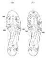
従来のスタッド着脱式のラグビーシューズとしては、図11(a)に示すように、前足部に4本のスタッド100が配置され、踵部に2本のスタッド101が配置された6本構造のもの(特開平7−313202号公報参照)や、同図(b)に示すように、前足部に6本のスタッド100が配置され、踵部に2本のスタッド101が配置された8本構造のものが主流であった。なお、同図中の一点鎖線は、着用者の足の骨格構造を示している。
【0003】
【特許文献1】
特開平7−313202号公報(図2)
【0004】
本願発明に係る発明者は、とくにラグビーシューズのアウトソール構造、その中でもスタッド配置やソール剛性について見直しを図るべく、実際の競技中においてステップ時やスクラムを組んだ際にプレーヤーの足裏に作用する力についてバイオメカニクスの観点から分析を行った。
【0005】
その結果、これまで慣用的に行われてきたスタッド配置をさらに改良する余地のあることが判明した。さらに、このようなスタッド配置に加え、スクラム時やステップ時のグリップ力をさらに向上させ、出足の一歩をさらにリードできるようにしたいとする要請もあった。
【0006】
本発明は、このような従来の実情に鑑みてなされたもので、競技時に要求される競技者の動きに応じてグリップ力を確実に接地面に伝達できるアウトソール構造を提供することを目的とする。
【0007】
【課題を解決するための手段】
そこで、本願発明に係る発明者は、競技中にラグビープレーヤーの足に実際に作用する足圧の分布状態を測定した。この測定結果を図2および図3に示す。図2はスクラム時の足圧分布図であり、図3はステップ時の足圧分布図である。各図とも左足の足裏側から見た足圧分布を示しており、図中、Mは内甲側を、Lは外甲側をそれぞれ示しており、また、内側の等圧線ほど圧力が高いことを示している。
【0008】
これらの図から、スクラム時には、第1足指の末節骨から中足骨骨頭にかけての領域、ならびに第2足指の中足趾節関節およびその周囲を含む領域において、足圧が相対的に高くなっている。また、ステップ時には、第1足指の末節骨から基節骨骨頭にかけての領域、第1足指から第3足指の各中足趾節関節およびその周囲を含む領域、ならびに踵部の領域において、足圧が相対的に高くなっている。
【0009】
本発明は、このように、実際の足圧分布の測定結果を考察することによりなされたものであって、請求項1の発明に係るフットボールシューズのアウトソール構造は、アウトソールの底面において、着用者の足指の第2趾中足趾節関節および第3趾中足趾節関節の中間位置付近に対応する位置に第1のスタッドを配置したことを特徴としている。
【0010】
図2および図3の足圧分布図から、スクラム時およびステップ時のいずれの場合においても、足裏の踏付部の略中央部分の足圧が高くなっていることが分かる。第1のスタッドは、この踏付部の略中央部分の足圧が高い位置に対応して配置されている。すなわち、図4および図5のアウトソール底面図に示すように、第1のスタッド11は、足指の第2趾中足趾節関節MJ2および第3趾中足趾節関節MJ3の中間位置付近(つまり中間位置およびその近傍を含む領域)に対応する位置に配置されている。
【0011】
この場合には、スクラム時およびステップ時に最も大きな力が作用する部位にスタッドが配置されるので、足裏からの力をロスなく接地面に伝えることができ、競技時に要求される競技者の動きに応じてグリップ力を確実に接地面に伝達できるようになり、これにより、出足の一歩をリードできるようになる。
【0012】
また、最も大きな足圧が作用するアウトソール部位が第1のスタッドにより下方から支持されるので、足の踏付部の下方への落ち込みを防止できる。このような横アーチの落ち込み等の防止によって足の障害を防止できるとともに、アウトソールひいてはシューズの変形を防止して耐久性を向上できる。
【0013】
なお、第1のスタッドの位置について、第2趾中足趾節関節MJ2および第3趾中足趾節関節MJ3の中間位置の近傍まで含めたのは、着用者の足には、足指の長短などの個体差があることを考慮したためである。
【0014】
請求項2の発明においては、第1のスタッドに加えて、足指の第1趾末節骨に相当する位置に第2のスタッドが、第1趾中足骨の骨頭付近に対応する位置に第3のスタッドがそれぞれ配置されている。
【0015】
図4および図5に示すように、第2のスタッド12および第3のスタッド13は、スクラム時およびステップ時に足圧が上昇する部位に対応して配置されている。これにより、競技者の動きに応じてグリップ力をより確実に接地面に伝達できるようになる。
【0016】
請求項3の発明においては、第1ないし第3のスタッドに加えて、足指の第3趾末節骨に対応する位置に第4のスタッドが、第4趾中足趾節関節および第5趾中足趾節関節の中間位置付近に対応する位置に第5のスタッドがそれぞれ配置されている。
【0017】
この場合には、アウトソールの前足部のスタッドが、それぞれ最適位置に配置された最少本数の5本のスタッドから構成されるので、足の外側への倒れ込みを防止しつつ、シューズのフラットな接地を実現できる。
【0018】
請求項4の発明においては、第1のスタッドの長さを第3および第5のスタッドの長さよりも短くすることにより、第1のスタッドの最突出端の位置が第3および第5のスタッドの最突出端の位置に対して、略同一の平面上に配置されており、または若干上方の位置に配置されている。
【0019】
アウトソールの底面が下方に突出する緩やかな湾曲形状を有している場合、第1のスタッドの長さを第3および第5のスタッドの長さと同じにすると、中央側の第1のスタッドの方が側縁部側の第3および第5のスタッドよりも下方に突出することになって、接地時の局部的な突き上げ感が増加し、足の障害が発生するおそれがある。
【0020】
しかしながら、請求項4の発明では、第1のスタッドの長さを第3および第5のスタッドの長さよりも短くして、第1のスタッドの最突出端の位置を第3および第5のスタッドの最突出端の位置に対して、略面一の位置または若干上方の位置に配置したので、シューズのフラット設置が可能になるとともに、接地時の局部的な突き上げ感を緩和でき、足の障害を防止できる。
【0021】
請求項5の発明においては、各足指の中足趾節関節付近の位置から基節骨骨頭付近の位置にかけてのアウトソール領域が他のアウトソール領域よりも高剛性にされている。
【0022】
この場合には、スクラム時やステップ時において足圧が高くなるスタッド間のアウトソール領域の落ち込みが防止されると同時に、当該アウトソール領域の反発性を向上でき、これにより、出足の一歩をリードできるようになり、次の動作にスムーズに移行できるようになる。
【0023】
また、一部のアウトソール領域を高剛性にすることで、他の大部分のアウトソール領域を薄肉にして低剛性にすることができ、これにより、アウトソール全体を軽量化できる。
【0024】
請求項6の発明においては、足指の第1趾中足趾節関節および第2趾中足趾節関節付近の位置から第1趾基節骨および第2趾基節骨の各骨頭付近の位置にかけてのアウトソール領域が他のアウトソール領域よりも高剛性にされている。また、請求項8の発明では、高剛性の領域が第1ないし第3の各スタッドの配設位置を含んでいる。
【0025】
これらの場合には、スクラム時やステップ時において足圧が最も高くなる第1ないし第3のスタッドに囲まれたアウトソール領域の剛性が高く設定されることになるので、当該アウトソール領域のたわみや落ち込みを防止して反発性を向上でき、これにより、スクラム時に力強いスクラムを組めるようになるとともに、ステップ時に足を踏み込んだ際に次の動作によりスムーズに移行できるようになって鋭いステップを踏めるようになる。
【0026】
請求項7の発明では、高剛性の領域の少なくとも一部が他の領域よりも厚肉に形成されている。
【0027】
請求項9の発明では、高剛性の領域の硬度が他の領域の硬度よりも高くなっている。また、請求項10の発明では、高剛性の領域が、たとえばカーボンファイバー等の補強部材を有している。これらの場合には、高剛性の領域の重量を増加させることなく、剛性のアップが可能であり、これにより、他のアウトソール領域の軽量化と相俟って、アウトソール全体をさらに軽量化できる。
【0028】
請求項11または13の発明においては、アウトソールの底面において、着用者の第1趾ないし第5趾の少なくとも一つに対応して前後方向に延びるリブが配設されている。また、請求項12または14の発明においては、アウトソールの底面において、着用者の第1趾ないし第4趾にそれぞれ対応して前後方向に延びる4本のリブが配設されている。
【0029】
これらの場合には、各リブ間のアウトソール部分の左右への屈曲性が向上し、これにより、ステップ時のグリップ力を向上できるとともに、ステップ時にスムーズな体重移動が可能になる。また、一部の足指を含む前後方向部分をリブによって補強することにより、他の部分を薄肉にすることができ、これにより、アウトソール全体の軽量化が可能である。
【0030】
請求項15または16の発明のおいては、アウトソールの底面において、前後方向に延びるリブがアウトソールの土踏まず部に配設されている。この場合には、土踏まず部つまりアーチ部の剛性を向上させることにより、縦アーチの落ち込みを防止でき、これにより、グリップ力が要求されるアウトソール領域のみによる接地状態を維持してグリップ力を確実に接地面に伝達できるとともに、プロネーション(回内)を防止して足の障害を回避できる。また、土踏まず部にリブを設けることで他の部分を薄肉にして低剛性にすることができ、これにより、アウトソール全体の軽量化に寄与できる。
【0031】
請求項17または18の発明においては、アウトソールの土踏まず部のリブには、幅方向の溝が形成されている。
【0032】
請求項19の発明においては、アウトソールの踵部、中足部または前足部に緩衝構造体が設けられているので、アウトソールの踵部、中足部または前足部の安定性を損なわずにクッション性を向上でき、着用者の足の踵部、中足部または前足部に障害が発生するのを防止できる。
【0033】
請求項20の発明においては、緩衝構造体が、それぞれシューズ前後方向に帯状に延びかつそれぞれ波板状に形成された複数の波形プレートを互いに並設して連結することにより構成されている。
【0034】
この場合には、競技時において着地の際にシューズの踵部または前足部に衝撃荷重が作用したとき、各波形プレートの波形状の山の部分が下方に沈み込むように変形するとともに、波形状の谷の部分が上方に持ち上がるように変形することにより、衝撃荷重を吸収できる。また、この場合には、隣り合う各波形プレートの連結部分が各波形状部分の変形を抑制するので、各波形状部分の変形と相俟って衝撃荷重をより効果的に吸収できる。
【0035】
請求項21の発明においては、各波形プレートの波形状の位相が、隣り合う波形プレートの波形状の位相に対して1/2波長だけずれている。
【0036】
請求項22の発明では、フットボールシューズがラグビーシューズである。
【0037】
請求項23の発明では、少なくとも第1のスタッドが着脱式のスタッドである。
【0038】
【発明の実施の形態】
以下、本発明の実施態様を添付図面に基づいて説明する。
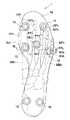
図1ないし図10は、本発明の一実施態様によるラグビーシューズのアウトソール構造を説明するための図であって、図1は本発明によるスタッド配列を有するアウトソールの底面図を足の骨格構造とともに示す図、図2はラグビー競技においてスクラムの際に足裏に実際に作用する足圧の分布図、図3はラグビー競技においてステップ時に足裏に実際に作用する足圧の分布図、図4はアウトソール(図1)を足圧部分図(図2)とともに示す図、図5はアウトソール(図1)を足圧部分図(図3)とともに示す図、図6は図1のVI−VI 線断面図、図7は本発明の好ましい実施態様によるアウトソールの底面図を足の骨格構造とともに示す図、図8は図7のVIII−VIII 線断面図、図9は図7のIX矢視図、図10は図7のアウトソールの踵部に設けられる緩衝構造体の斜視部分図である。なお、ここでは、左足用のアウトソールを例にとっている。また、各図中、足の骨格構造が一点鎖線で示されており、各図中、DP,MP,PP,MB,MJはそれぞれ足の末節骨、中節骨、基節骨、中足骨、中足趾節関節を示しており、添字の1〜5はそれぞれ足の第1趾ないし第5趾を表している。
【0039】
図1に示すように、アウトソール1の底面1aには、第1ないし第5のスタッド11〜15が設けられている。第1のスタッド11は、着用者の足指の第2趾中足趾節関節MJ2および第3趾中足趾節関節MJ3の中間位置付近(つまり中間位置およびその近傍を含む領域(以下同様))に対応する位置に配置されている。
【0040】
第2のスタッド12は、足指の第1趾末節骨DP1に対応する位置に配置されており、第3のスタッド13は、第1趾中足骨MB1の骨頭付近に対応する位置に配置されている。第4のスタッド14は、足指の第3趾末節骨DP3に対応する位置に配置されており、第5のスタッド15は、第4趾中足趾節関節MJ4および第5趾中足趾節関節MJ5の中間位置付近に対応する位置に配置されている。さらに、踵部には、スタッド18,19が設けられている。
【0041】
次に、競技中にラグビープレーヤーの足に実際に作用する足圧の分布状態を測定した測定結果を図2および図3に示す。図2はスクラム時の足圧分布図であり、図3はステップ時の足圧分布図である。各図とも左足の足裏側から見た足圧分布を示しており、図中、Mは内甲側を、Lは外甲側をそれぞれ示している。また、内側の等圧線ほど圧力が高いことを示している。
【0042】
これらの図から、スクラム時には、第1足指の末節骨DP1から中足骨MB1骨頭付近にかけての領域、ならびに第2足指の中足趾節関節MJ2およびその周囲を含む領域において、足圧が相対的に高くなっていることが分かる。また、ステップ時には、第1足指の末節骨DP1から基節骨PP1骨頭付近にかけての領域、第1足指から第3足指の各中足趾節関節MJ1,MJ2,MJ3およびその周囲を含む領域、ならびに踵部の領域において、足圧が相対的に高くなっていることが分かる。
【0043】
次に、図2および図3の足圧分布図を図1のアウトソールに重ね合わせたものをそれぞれ図4および図5に示す。これらの図から明らかなように、第1ないし第3のスタッド11〜13は、図2および図3の足圧分布に非常によく一致した位置に配置されていることが分かる。
【0044】
第1ないし第3のスタッド11〜13のうち、第1のスタッド11が、本実施態様によるアウトソール構造においてとくに重要なものであって、図2および図3の足圧分布図から分かるように、スクラム時およびステップ時のいずれの場合においても、足裏の踏付部の略中央部分の足圧が高くなっている。第1のスタッド11は、この踏付部の略中央部分の足圧が高い位置に対応して配置されている。同様に、第2および第3のスタッド12,13についても、図2および図3の足圧分布図において足圧が高い位置に対応して配置されている。
【0045】
この場合には、スクラム時およびステップ時に最も大きな力が作用する部位に第1ないし第3のスタッド11〜13が配置されるので、足裏からの力をロスなく接地面に伝えることができ、競技時に要求される競技者の動きに応じてグリップ力を確実に接地面に伝達できるようになり、これにより、出足の一歩をリードできるようになる。
【0046】
また、最も大きな足圧が作用するアウトソール部位が第1のスタッド11により下方から支持されるので、足の踏付部の下方への落ち込みを防止できる。このような横アーチの落ち込み等の防止によって足の障害を防止できるとともに、アウトソールひいてはシューズの変形を防止して耐久性を向上できる。
【0047】
アウトソール1の底面1aには、第1ないし第3のスタッド11〜13に加えて、足指の第3趾末節骨DP3に対応する位置に第4のスタッド14が、第4趾中足趾節関節MJ4および第5趾中足趾節関節MJ5の中間位置付近に対応する位置に第5のスタッド15がそれぞれ配置されている。
【0048】
この場合には、アウトソールの前足部のスタッドが、それぞれ最適位置に配置された最少本数の5本のスタッド11〜15から構成されるので、アウトソール全体の重量の増加を抑制しつつ、足の外側への倒れ込みを防止でき、シューズのフラットな接地を実現できる。なお、各スタッド11〜15は、固定式または着脱式(取替式)のいずれであってもよい。とくに第1のスタッド11は、接地頻度が高く比較的摩耗も速いため、取替式の方が好ましい。
【0049】
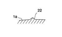
図6に示すように、第1のスタッド11の長さは、第3および第5のスタッド13,15の長さよりも短くなっており、同図中の一点鎖線Hに示すように、第1のスタッド11の最突出端の位置は、第3および第5のスタッド13,15の最突出端の位置と略同一の平面H上に配置されている。あるいは、第1のスタッド11の最突出端の位置は、第3および第5のスタッド13,15の最突出端の位置よりも若干上方に配置されていてもよい。これらの場合には、シューズのフラット設置が可能になるとともに、接地時の局部的な突き上げ感を緩和でき、その結果、足の障害を防止できる。
【0050】
なお、アウトソール1の底面1aは、下方に突出する緩やかな湾曲形状を有しているため(図6参照)、仮に第1、第3および第5のスタッド11,13,15の長さを同じにすると、中央側の第1のスタッド11の方が側縁部側の第3および第5のスタッド13,15よりも下方に突出することになって、接地時の局部的な突き上げ感が増加することになるが、本実施態様によるアウトソールでは、このような不具合の発生を防止できる。
【0051】
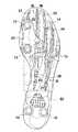
次に、図7に示す本発明の好ましい実施態様においては、第1ないし第3の各スタッド11〜13を連結する略三角形状の領域に厚肉部20が形成されている。すなわち、厚肉部20は、第1趾中足趾節関節MJ1および第2趾中足趾節関節MJ2付近の位置から第1趾末節骨DP1付近の位置にかけてのアウトソール領域を覆っている。
【0052】
この場合には、スクラム時やステップ時において足圧が最も高くなるアウトソール領域の剛性が高く設定されることになるので、スクラム時やステップ時に当該アウトソール領域の落ち込みが防止されると同時に、当該アウトソール領域の反発性を向上でき、これにより、スクラム時に力強いスクラムを組めるようになるとともに、ステップ時に足を踏み込んだ際に次の動作によりスムーズに移行できるようになって鋭いステップを踏めるようになる。また、このように一部のアウトソール領域を高剛性にすることで、他の大部分のアウトソール領域を薄肉にして低剛性にすることができ、これにより、アウトソール全体を軽量化できる。
【0053】
なお、高剛性のアウトソール領域として、厚肉部20を形成するかわりに、当該アウトソール領域を他のアウトソール領域よりも高硬度の素材から形成するようにしてもよく、あるいは、当該アウトソール領域にたとえばカーボンファイバー等の補強部材を設けるようにしてもよい。これらの場合には、高剛性の領域の重量を増加させることなく、剛性のアップが可能であり、これにより、他のアウトソール領域の軽量化と相俟って、アウトソール全体をさらに軽量化できる。
【0054】
また、高剛性にするアウトソール領域としては、各足指の中足趾節関節MJ付近の位置から基節骨PP骨頭付近の位置にかけての踏付部全体に配置するようにしてもよい。
【0055】
図7に示すように、アウトソール1の底面1aにおいて、着用者の第1趾ないし第4趾に対応して前後方向に延びる4本のリブ21〜24が配設されており、各リブ21〜24はつま先部から中足部にかけて配設されている。リブ21,22は中足部のリブ25に連結されており、リブ23,24は同様に中足部のリブ26に連結されている。また、各リブ21〜26は、図8に示すように、底面1aから突出する山形形状を有している。
【0056】
この場合には、各足指を含む前後方向部分がリブによって補強されることにより、他のアウトソール領域を薄肉にすることができる。これにより、アウトソール全体の軽量化が可能である。また、この場合には、各リブ間のアウトソール部分の左右への屈曲性が向上し、これにより、ステップ時に各リブ間のアウトソール部分の屈曲変形が容易になって、グリップ力を向上できるとともに、ステップ時にスムーズな体重移動が可能になる。
【0057】
なお、図7では、第1趾ないし第4趾のすべての足指に対応して4本のリブ21〜24を設けた例を示したが、これらの4本のうちの少なくとも1本のリブ、たとえば第1趾および第2趾に対応した2本のリブ21,22を設けるようにしてもよい。また、第5趾に対応した前後方向のリブをさらに設けるようにしてもよい。
【0058】
アウトソール1の底面1aにおいて、土踏まず部(中足部)に前後方向のリブ25,26が配設されていることにより、土踏まず部つまりアーチ部の剛性を向上させることができ、これにより、縦アーチの落ち込みを防止できる。その結果、グリップ力が要求されるアウトソール領域のみによる接地状態を維持してグリップ力を確実に接地面に伝達できるとともに、プロネーション(回内)を防止して足の障害を回避できる。また、土踏まず部にリブを設けることで他の部分を薄肉にして低剛性にすることができ、これにより、アウトソール全体の軽量化に寄与できる。
【0059】
また、リブ25,26には、図9に示すように、幅方向に延びる複数の溝27が形成されている。この場合には、これらの溝27にシューズの靴紐を通して緊締することにより、より強固な緊締が可能になってフィット性を向上でき、接地面に対してロスなく確実にグリップ力を伝達できるようになる。
【0060】
さらに、アウトソール1の踵部には、緩衝構造体50が設けられている。緩衝構造体50は、斜視部分図である図10に示すように、それぞれシューズ前後方向に帯状に延びかつそれぞれ波板状に形成された複数の波形プレート51,52を互いに並設することにより構成されており、各波形プレート51,52の波形状の位相は、隣り合う波形プレート52,51の波形状の位相に対して1/2波長だけずれている。また、各波形プレート51,52は、連結部53により互いに連結されている。
【0061】
この場合には、競技時において着地の際にシューズの踵部に衝撃荷重が作用したとき、各波形プレート51,52の波形状の山の部分が下方に沈み込むように変形するとともに、波形状の谷の部分が上方に持ち上がるように変形することによって、踵部に作用する衝撃荷重を吸収できる。また、隣り合う各波形プレート51,52の連結部分53が各波形状部分の変形を抑制することにより、各波形状部分の変形と相俟って衝撃荷重をより効果的に吸収できる。これにより、踵部のクッション性を向上でき、着用者の足の踵部に障害が発生するのを防止できる。なお、緩衝構造体50は、アウトソール1の中足部または前足部に設けるようにしてもよい。
【0062】
〔他の適用例〕
前記実施態様および各変形例では、ラグビーシューズを例にとって説明してきたが、本発明は、ラグビーシューズ以外のサッカー、アメリカンフットボールなどの他のフットボール用シューズにも適用可能である。
【0063】
【発明の効果】
以上のように、本発明によれば、競技時に要求される競技者の動きに応じてグリップ力を確実に接地面に伝達できる効果がある。
【図面の簡単な説明】
【図1】本発明の一実施態様によるスタッド配列を有するアウトソールの底面図を足の骨格構造とともに示す図である。
【図2】ラグビー競技においてスクラムの際に足裏に実際に作用する足圧の分布図である。
【図3】ラグビー競技においてステップ時に足裏に実際に作用する足圧の分布図である。
【図4】図1のアウトソールを図2の足圧部分図とともに示す図である。
【図5】図1のアウトソールを図3の足圧部分図とともに示す図である。
【図6】図1のVI−VI 線断面図である。
【図7】本発明の好ましい実施態様によるアウトソールの底面図を足の骨格構造とともに示す図である。
【図8】図7のVIII−VIII 線断面図である。
【図9】図7のIX矢視図である。
【図10】図7のアウトソールの踵部に設けられる緩衝構造体の斜視部分図である。
【図11】従来のスタッド着脱式(取替式)のラグビーシューズの底面図であって、(a)はスタッドが6本配列のものを、(b)はスタッドが8本配列のものをそれぞれ示している。
【符号の説明】
1: アウトソール
1a: 底面
11: 第1のスタッド
12: 第2のスタッド
13: 第3のスタッド
14: 第4のスタッド
15: 第5のスタッド
DP: 末節骨
MP: 中節骨
PP: 基節骨
MB: 中足骨
MJ: 中足趾節関節[0001]
TECHNICAL FIELD OF THE INVENTION
The present invention relates to an outsole structure for a football shoe, and more particularly to an improvement in an outsole structure suitable for rugby shoes and soccer shoes.
[0002]
[Prior art and its problems]
As a conventional stud detachable rugby shoe, as shown in FIG. 11A, six studs in which four
[0003]
[Patent Document 1]
JP-A-7-313202 (FIG. 2)
[0004]
In order to review the outsole structure of rugby shoes, especially stud arrangement and sole rigidity, the inventor according to the present invention acts on the sole of the player when stepping or scramming during an actual competition. The force was analyzed from the viewpoint of biomechanics.
[0005]
As a result, it has been found that there is room for further improvement of the stud arrangement conventionally used conventionally. Further, in addition to such stud arrangement, there has been a demand that the grip force at the time of scram or step be further improved so that one step of starting can be further led.
[0006]
The present invention has been made in view of such conventional circumstances, and has as its object to provide an outsole structure that can reliably transmit a grip force to a ground contact surface in accordance with a player's movement required during a competition. I do.
[0007]
[Means for Solving the Problems]
Then, the inventor according to the present invention measured the distribution of foot pressure actually acting on the feet of the rugby player during the competition. The measurement results are shown in FIG. 2 and FIG. FIG. 2 is a foot pressure distribution diagram at the time of the scrum, and FIG. 3 is a foot pressure distribution diagram at the time of the step. Each figure shows the foot pressure distribution as viewed from the sole side of the left foot. In the figures, M indicates the inner back side, L indicates the outer back side, and the inner isobar shows the higher pressure. Is shown.
[0008]
From these figures, it can be seen from the figures that the foot pressure is relatively high in the region from the distal phalanx of the first toe to the metatarsal head and in the region including the metatarsophalangeal joint of the second toe and its surroundings during the scrum. Has become. In addition, at the time of the step, in the region from the distal phalanx to the proximal phalanx of the first toe, the region including the metatarsophalangeal joints of the first to third toes and their surroundings, and the region of the heel , The foot pressure is relatively high.
[0009]
Thus, the present invention has been made by considering the measurement results of actual foot pressure distribution, and the outsole structure of the football shoe according to the first aspect of the present invention is worn on the bottom surface of the outsole. The first stud is arranged at a position corresponding to a position near an intermediate position between the second and third metatarsophalangeal joints of the toe of the person.
[0010]
From the foot pressure distribution diagrams of FIGS. 2 and 3, it can be seen that the foot pressure at the substantially central portion of the tread portion on the sole is high in both the scrum and step modes. The first stud is arranged corresponding to a position where the foot pressure is high at a substantially central portion of the tread portion. That is, as shown in the outsole bottom view of FIG. 4 and FIG. 5, the
[0011]
In this case, the stud is placed at the position where the greatest force acts during scrum and step, so that the force from the sole can be transmitted to the ground without loss, and the movement of the competitor required during the competition As a result, the grip force can be reliably transmitted to the ground contact surface, so that one step of starting can be led.
[0012]
Further, since the outsole portion on which the greatest foot pressure acts is supported from below by the first stud, it is possible to prevent the stepping portion of the foot from falling downward. The prevention of such a fall of the lateral arch can prevent the obstacle of the foot, and the deformation of the outsole and thus the shoe can be prevented to improve the durability.
[0013]
Note that the position of the first stud, was included to the vicinity of an intermediate position of the second趾中metatarsophalangeal joints MJ2 and third趾中metatarsophalangeal joints MJ3 is the wearer's foot, foot This is because there is an individual difference such as the length of the finger.
[0014]
In the invention of claim 2, in addition to the first stud, the second stud is located at a position corresponding to the first distal phalanx of the toe, and the second stud is located at a position corresponding to the vicinity of the head of the first metatarsal. Three studs are respectively arranged.
[0015]
As shown in FIGS. 4 and 5, the
[0016]
In the invention of claim 3, in addition to the first to third studs, a fourth stud is provided at a position corresponding to the third phalange of the third toe of the toe, the fourth toe metatarsophalangeal joint and the fifth toe. Fifth studs are respectively arranged at positions corresponding to the middle positions of the metatarsophalangeal joints.
[0017]
In this case, the studs of the forefoot portion of the outsole are each composed of the minimum number of five studs arranged at the optimum positions, so that the shoes can be prevented from falling down to the outside and the flat ground of the shoes can be prevented. Can be realized.
[0018]
In the invention according to claim 4, the length of the first stud is made shorter than the length of the third and fifth studs, so that the position of the most protruding end of the first stud is changed to the third and fifth studs. Are located on substantially the same plane with respect to the position of the most protruding end, or are located slightly above.
[0019]
When the bottom surface of the outsole has a gentle curved shape protruding downward, if the length of the first stud is the same as the length of the third and fifth studs, the first stud on the center side is The lower side protrudes lower than the third and fifth studs on the side edge side, so that the feeling of local thrust-up at the time of touching the ground increases, and there is a possibility that a foot failure may occur.
[0020]
However, in the invention of claim 4, the length of the first stud is made shorter than the length of the third and fifth studs, and the position of the most protruding end of the first stud is set to the third and fifth studs. It is located almost flush or slightly above the position of the most protruding end of the shoe, so that the shoes can be installed flat and the feeling of local push-up at the time of touchdown can be alleviated, resulting in foot obstacles. Can be prevented.
[0021]
In the invention of claim 5, the outsole region from the position near the metatarsophalangeal joint of each toe to the position near the proximal phalanx head is made more rigid than the other outsole regions.
[0022]
In this case, it is possible to prevent the outsole area from falling between the studs where the foot pressure becomes high during a scrum or a step, and at the same time, it is possible to improve the resilience of the outsole area. It is possible to smoothly move to the next operation.
[0023]
In addition, by making some of the outsole regions highly rigid, it is possible to make most of the other outsole regions thin and low in rigidity, thereby reducing the weight of the entire outsole.
[0024]
In the invention of claim 6, the positions of the first and second metatarsophalangeal joints of the toes from the vicinity of the first and second metatarsophalangeal joints to the vicinity of the respective heads of the first toe proximal phalanx and the second toe proximal phalange The outsole region over the position is made more rigid than the other outsole regions. In the invention according to claim 8, the high-rigidity region includes the arrangement positions of the first to third studs.
[0025]
In these cases, the rigidity of the outsole region surrounded by the first to third studs at which the foot pressure is highest during scram or step is set to be high, so that the deflection of the outsole region This helps to improve the resilience by preventing falling and falling, so that a strong scrum can be assembled at the time of the scrum, and when stepping on the step, the next movement can make a smooth transition and the sharp step can be taken Become like
[0026]
In the invention of claim 7, at least a part of the high-rigidity region is formed thicker than other regions.
[0027]
According to the ninth aspect, the hardness of the high-rigidity area is higher than the hardness of the other areas. According to the tenth aspect, the high-rigidity region has a reinforcing member such as carbon fiber. In these cases, the rigidity can be increased without increasing the weight of the high rigidity area, which, together with the weight reduction of other outsole areas, further reduces the overall weight of the outsole. it can.
[0028]
According to the eleventh or thirteenth aspect, a rib extending in the front-rear direction corresponding to at least one of the first to fifth toes of the wearer is provided on the bottom surface of the outsole. In the twelfth or fourteenth aspect of the present invention, four ribs extending in the front-rear direction are provided on the bottom surface of the outsole, corresponding to the first to fourth toes of the wearer, respectively.
[0029]
In these cases, the flexibility of the outsole portion between the ribs to the left and right is improved, whereby the grip force at the time of stepping can be improved and the weight can be smoothly moved at the time of stepping. In addition, by reinforcing the fore-and-aft portion including a part of the toe with the rib, the other portion can be made thinner, whereby the weight of the entire outsole can be reduced.
[0030]
In the invention according to claim 15 or 16, on the bottom surface of the outsole, a rib extending in the front-rear direction is provided on an arch portion of the outsole. In this case, it is possible to prevent the vertical arch from dropping by improving the rigidity of the arch portion, that is, the arch portion, thereby maintaining the ground contact state only in the outsole area where the grip force is required and ensuring the grip force. In addition to being able to transmit to the ground contact surface, pronation (pronation) can be prevented and foot injury can be avoided. In addition, by providing a rib on the arch portion, the other portion can be made thinner to have low rigidity, thereby contributing to weight reduction of the entire outsole.
[0031]
In the invention according to claim 17 or 18, a groove in the width direction is formed in the rib of the arch portion of the outsole.
[0032]
In the invention of
[0033]
According to the twentieth aspect, the buffer structure is configured by connecting a plurality of corrugated plates, each of which extends in a belt shape in the front-rear direction of the shoe and is formed in a corrugated shape, in parallel with each other.
[0034]
In this case, when an impact load is applied to the heel or forefoot of the shoe during landing at the time of the competition, the corrugated peaks of each corrugated plate are deformed so as to sink down, and the corrugated The impact load can be absorbed by deforming the valley portion so as to lift upward. Further, in this case, since the connecting portions of the adjacent corrugated plates suppress the deformation of each corrugated portion, the impact load can be more effectively absorbed together with the deformation of each corrugated portion.
[0035]
According to the twenty-first aspect, the phase of the wave shape of each waveform plate is shifted by 波長 wavelength from the phase of the waveform of an adjacent waveform plate.
[0036]
According to the invention of
[0037]
In the invention of
[0038]
BEST MODE FOR CARRYING OUT THE INVENTION
Hereinafter, embodiments of the present invention will be described with reference to the accompanying drawings.
1 to 10 are views for explaining an outsole structure of a rugby shoe according to an embodiment of the present invention, and FIG. 1 is a bottom view of an outsole having a stud arrangement according to the present invention. FIG. 2 is a distribution diagram of foot pressure actually acting on the sole during a scrum in a rugby game, FIG. 3 is a distribution diagram of foot pressure actually acting on the sole during a step in a rugby game, and FIG. FIG. 5 shows the outsole (FIG. 1) together with the foot pressure partial view (FIG. 2), FIG. 5 shows the outsole (FIG. 1) together with the foot pressure partial view (FIG. 3), and FIG. 6 shows VI- in FIG. FIG. 7 is a sectional view taken along the line VI, FIG. 7 is a view showing a bottom view of the outsole according to the preferred embodiment of the present invention together with the skeletal structure of the foot, FIG. 8 is a sectional view taken along the line VIII-VIII of FIG. FIG. 10 is a perspective view of FIG. It is a perspective partial view of a cushioning structure provided in the heel portion of the sole. Here, the outsole for the left foot is taken as an example. In each figure, the skeletal structure of the foot is indicated by a dashed line, and in each figure, DP, MP, PP, MB, and MJ are the distal phalanx, the middle phalanx, the basal phalanx, and the metatarsal bone, respectively. And the metatarsophalangeal joints, and the
[0039]
As shown in FIG. 1, first to
[0040]
The
[0041]
Next, FIG. 2 and FIG. 3 show measurement results obtained by measuring the distribution of foot pressure actually acting on the feet of the rugby player during the game. FIG. 2 is a foot pressure distribution diagram at the time of the scrum, and FIG. 3 is a foot pressure distribution diagram at the time of the step. Each figure shows the distribution of foot pressure as viewed from the sole side of the left foot. In the figures, M indicates the instep side, and L indicates the outer side. In addition, the pressure is higher as the inner isobar is higher.
[0042]
From these figures, in the region at the time of scram, including metatarsophalangeal joints MJ2 and around the region of the over the near metatarsus MB1 condyle from the distal phalanx DP1 of the first toe and the second toe, It can be seen that the foot pressure is relatively high. Also, during step, a region from the distal phalanx DP1 toward the vicinity of the proximal phalanx PP1 condyles of the first toe, each leg of the third toe of the first toe metatarsophalangeal jointsMJ1, MJ 2, MJ3 It can be seen that the foot pressure is relatively high in the region including and around the region, and in the region of the heel.
[0043]
Next, FIGS. 4 and 5 show the foot pressure distribution diagrams of FIGS. 2 and 3 superimposed on the outsole of FIG. 1, respectively. As is clear from these figures, it can be seen that the first to
[0044]
Of the first to
[0045]
In this case, since the first to
[0046]
In addition, since the outsole portion where the greatest foot pressure acts is supported from below by the
[0047]
The
[0048]
In this case, the studs of the forefoot part of the outsole are each composed of the minimum number of five
[0049]
As shown in FIG. 6, the length of the
[0050]
Since the
[0051]
Next, in a preferred embodiment of the present invention shown in FIG. 7, a
[0052]
In this case, the rigidity of the outsole region where the foot pressure is highest at the time of scram or step is set to be high, so that the outsole region is prevented from dropping at the time of scram or step, The resilience of the outsole area can be improved, so that a powerful scrum can be assembled at the time of scram, and when stepping on a step, the next operation can smoothly transition to enable a sharp step to be taken become. In addition, by making some of the outsole regions high in rigidity in this way, it is possible to make most of the other outsole regions thin and low in rigidity, thereby making it possible to reduce the weight of the entire outsole.
[0053]
Note that, instead of forming the
[0054]
In addition, the outsole region for increasing the rigidity may be arranged on the entire step portion from the position near the metatarsophalangeal joint MJ of each toe to the position near the head of the proximal phalanx PP.
[0055]
As shown in FIG. 7, on the
[0056]
In this case, the other outsole region can be made thin by reinforcing the front-back portion including each toe with the rib. Thereby, the weight of the entire outsole can be reduced. Further, in this case, the outsole portion between the ribs is more flexibly to the left and right, whereby the outsole portion between the ribs can be easily bent and deformed at the time of stepping, and the grip force can be improved. At the same time, a smooth weight shift at the time of the step becomes possible.
[0057]
Although FIG. 7 shows an example in which four
[0058]
On the
[0059]
As shown in FIG. 9, a plurality of
[0060]
Further, a
[0061]
In this case, when an impact load is applied to the heel portion of the shoe at the time of landing during a game, the corrugated mountain portions of the
[0062]
[Other application examples ]
Although the above-described embodiment and each modified example have been described by taking rugby shoes as an example, the present invention is also applicable to other football shoes such as soccer and American football other than rugby shoes.
[0063]
【The invention's effect】
As described above, according to the present invention, there is an effect that the grip force can be reliably transmitted to the ground contact surface in accordance with the movement of the competitor required during the competition.
[Brief description of the drawings]
FIG. 1 is a diagram showing a bottom view of an outsole having a stud arrangement according to an embodiment of the present invention, together with a foot skeletal structure.
FIG. 2 is a distribution diagram of foot pressure actually acting on a sole during a scrum in a rugby game.
FIG. 3 is a distribution diagram of foot pressure actually acting on the sole during stepping in a rugby game.
FIG. 4 is a view showing the outsole of FIG. 1 together with a foot pressure partial view of FIG. 2;
5 is a view showing the outsole of FIG. 1 together with a foot pressure partial view of FIG. 3;
FIG. 6 is a sectional view taken along line VI-VI of FIG. 1;
FIG. 7 shows a bottom view of an outsole according to a preferred embodiment of the present invention, together with a foot skeletal structure.
FIG. 8 is a sectional view taken along line VIII-VIII of FIG. 7;
FIG. 9 is a view on arrow IX of FIG. 7;
FIG. 10 is a partial perspective view of a cushioning structure provided on a heel portion of the outsole of FIG. 7;
11 is a bottom view of a conventional stud detachable (replaceable) rugby shoe, in which (a) shows a stud array with six studs, and (b) shows a stud array with eight studs. Is shown.
[Explanation of symbols]
1:
Claims (23)
Translated fromJapaneseアウトソールの底面において、着用者の足指の第2趾中足趾節関節および第3趾中足趾節関節の中間位置付近に対応する位置に第1のスタッドを配置した、
ことを特徴とするフットボールシューズのアウトソール構造。In the outsole structure of football shoes,
On the bottom surface of the outsole, the first stud was arranged at a position corresponding to a position near the middle position between the second and third metatarsophalangeal joints of the wearer's toes,
The outsole structure of a football shoe, characterized in that:
足指の第1趾末節骨に対応する位置に第2のスタッドを配置し、第1趾中足骨の骨頭付近に対応する位置に第3のスタッドを配置した、
ことを特徴とするフットボールシューズのアウトソール構造。In claim 1,
A second stud was placed at a position corresponding to the first distal phalanx of the toe, and a third stud was placed at a position corresponding to the vicinity of the head of the first metatarsal metatarsal;
The outsole structure of a football shoe, characterized in that:
足指の第3趾末節骨に対応する位置に第4のスタッドを配置し、第4趾中足趾節関節および第5趾中足趾節関節の中間位置付近に対応する位置に第5のスタッドを配置した、
ことを特徴とするフットボールシューズのアウトソール構造。In claim 2,
A fourth stud is placed at a position corresponding to the third distal phalanx of the toe, and a fifth stud is placed at a position corresponding to the vicinity of the middle position between the fourth and fifth metatarsophalangeal joints. Placed studs,
The outsole structure of a football shoe, characterized in that:
前記第1のスタッドの長さを前記第3および第5のスタッドの長さよりも短くすることにより、前記第1のスタッドの最突出端の位置が前記第3および第5のスタッドの最突出端の位置に対して、略同一の平面上に配置されており、または若干上方の位置に配置されている、
ことを特徴とするフットボールシューズのアウトソール構造。In claim 3,
By making the length of the first stud shorter than the length of the third and fifth studs, the position of the most protruding end of the first stud is changed to the most protruding end of the third and fifth studs. With respect to the position, is arranged on substantially the same plane, or is arranged at a position slightly above,
The outsole structure of a football shoe, characterized in that:
各足指の中足趾節関節付近の位置から基節骨骨頭付近の位置にかけてのアウトソール領域を他のアウトソール領域よりも高剛性にした、
ことを特徴とするフットボールシューズのアウトソール構造。In any one of claims 1 to 3,
The outsole area from the position near the metatarsophalangeal joint of each toe to the position near the proximal phalanx head was made more rigid than other outsole areas,
The outsole structure of a football shoe, characterized in that:
足指の第1趾中足趾節関節および第2趾中足趾節関節付近の位置から第1趾基節骨および第2趾基節骨の各骨頭付近の位置にかけてのアウトソール領域を他のアウトソール領域よりも高剛性にした、
ことを特徴とするフットボールシューズのアウトソール構造。In any one of claims 1 to 3,
The outsole region from the position near the first and second metatarsophalangeal joints of the toe to the position near each head of the first and second metatarsal phalanges of the toe Stiffer than the outsole area of
The outsole structure of a football shoe, characterized in that:
前記高剛性の領域の少なくとも一部が、他の領域よりも厚肉に形成されている、
ことを特徴とするフットボールシューズのアウトソール構造。In claim 5 or 6,
At least a part of the high-rigidity region is formed thicker than other regions.
The outsole structure of a football shoe, characterized in that:
前記高剛性の領域が、前記第1ないし第3の各スタッドの配設位置を含んでいる、
ことを特徴とするフットボールシューズのアウトソール構造。In claim 7,
The high-rigidity area includes an arrangement position of each of the first to third studs.
The outsole structure of a football shoe, characterized in that:
前記高剛性の領域の硬度が、他の領域の硬度よりも高くなっている、
ことを特徴とするフットボールシューズのアウトソール構造。In claim 5 or 6,
The hardness of the high rigidity region is higher than the hardness of the other regions,
The outsole structure of a football shoe, characterized in that:
前記高剛性の領域が補強部材を有している、
ことを特徴とするフットボールシューズのアウトソール構造。In claim 5 or 6,
The high-rigidity region has a reinforcing member,
The outsole structure of a football shoe, characterized in that:
アウトソールの底面において、着用者の第1趾ないし第5趾の少なくとも一つに対応して前後方向に延びるリブが配設されている、
ことを特徴とするフットボールシューズのアウトソール構造。In the outsole structure of football shoes,
On the bottom surface of the outsole, a rib extending in the front-rear direction corresponding to at least one of the first to fifth toes of the wearer is provided.
The outsole structure of a football shoe, characterized in that:
アウトソールの底面において、着用者の第1趾ないし第4趾にそれぞれ対応して前後方向に延びる4本のリブが配設されている、
ことを特徴とするフットボールシューズのアウトソール構造。In the outsole structure of football shoes,
On the bottom surface of the outsole, four ribs extending in the front-rear direction corresponding to the first to fourth toes of the wearer, respectively, are disposed.
The outsole structure of a football shoe, characterized in that:
アウトソールの底面において、着用者の第1趾ないし第5趾の少なくとも一つに対応して前後方向に延びるリブが配設されている、
ことを特徴とするフットボールシューズのアウトソール構造。In any one of claims 1 to 10,
On the bottom surface of the outsole, a rib extending in the front-rear direction corresponding to at least one of the first to fifth toes of the wearer is provided.
The outsole structure of a football shoe, characterized in that:
アウトソールの底面において、着用者の第1趾ないし第4趾にそれぞれ対応して前後方向に延びる4本のリブが配設されている、
ことを特徴とするフットボールシューズのアウトソール構造。In any one of claims 1 to 10,
On the bottom surface of the outsole, four ribs extending in the front-rear direction corresponding to the first to fourth toes of the wearer are provided,
The outsole structure of a football shoe, characterized in that:
アウトソールの底面において、前後方向に延びるリブがアウトソールの土踏まず部に配設されている、
ことを特徴とするフットボールシューズのアウトソール構造。In the outsole structure of football shoes,
On the bottom of the outsole, ribs extending in the front-rear direction are arranged on the arch part of the outsole,
The outsole structure of a football shoe, characterized in that:
アウトソールの底面において、前後方向に延びるリブがアウトソールの土踏まず部に配設されている、
ことを特徴とするフットボールシューズのアウトソール構造。In any one of claims 1 to 14,
On the bottom of the outsole, ribs extending in the front-rear direction are arranged on the arch part of the outsole,
The outsole structure of a football shoe, characterized in that:
アウトソールの土踏まず部のリブには、幅方向の溝が形成されている、
ことを特徴とするフットボールシューズのアウトソール構造。In the outsole structure of football shoes,
A groove in the width direction is formed in the rib of the arch part of the outsole,
The outsole structure of a football shoe, characterized in that:
アウトソールの土踏まず部のリブには、幅方向の溝が形成されている、
ことを特徴とするフットボールシューズのアウトソール構造。In any one of claims 11 to 16,
A groove in the width direction is formed in the rib of the arch part of the outsole,
The outsole structure of a football shoe, characterized in that:
アウトソールの踵部、中足部または前足部には、緩衝構造体が設けられている、
ことを特徴とするフットボールシューズのアウトソール構造。In any one of claims 1 to 18,
A buffer structure is provided on the heel, midfoot or forefoot of the outsole,
The outsole structure of a football shoe, characterized in that:
前記緩衝構造体は、それぞれシューズ前後方向に帯状に延びかつそれぞれ波板状に形成された複数の波形プレートを互いに並設して連結することにより構成されている、
ことを特徴とするフットボールシューズのアウトソール構造。In claim 19,
The buffer structure is configured by connecting a plurality of corrugated plates extending in a belt shape in the shoe front-rear direction and formed in a corrugated shape in parallel with each other, respectively.
The outsole structure of a football shoe, characterized in that:
前記各波形プレートの波形状の位相が、隣り合う波形プレートの波形状の位相に対して1/2波長だけずれている、
ことを特徴とするフットボールシューズのアウトソール構造。In claim 20,
The phase of the wave shape of each wave plate is shifted by 1 / wavelength from the phase of the wave shape of an adjacent wave plate;
The outsole structure of a football shoe, characterized in that:
前記フットボールシューズがラグビーシューズである、
ことを特徴とするフットボールシューズのアウトソール構造。In any one of claims 1 to 21,
The football shoes are rugby shoes,
The outsole structure of a football shoe, characterized in that:
少なくとも前記第1のスタッドが着脱式のスタッドである、
ことを特徴とするフットボールシューズのアウトソール構造。In any one of claims 1 to 22,
At least the first stud is a detachable stud,
The outsole structure of a football shoe, characterized in that:
Priority Applications (1)
| Application Number | Priority Date | Filing Date | Title |
|---|---|---|---|
| JP2002338049AJP3934036B2 (en) | 2002-11-21 | 2002-11-21 | Outsole structure of football shoes |
Applications Claiming Priority (1)
| Application Number | Priority Date | Filing Date | Title |
|---|---|---|---|
| JP2002338049AJP3934036B2 (en) | 2002-11-21 | 2002-11-21 | Outsole structure of football shoes |
Publications (2)
| Publication Number | Publication Date |
|---|---|
| JP2004167069Atrue JP2004167069A (en) | 2004-06-17 |
| JP3934036B2 JP3934036B2 (en) | 2007-06-20 |
Family
ID=32701382
Family Applications (1)
| Application Number | Title | Priority Date | Filing Date |
|---|---|---|---|
| JP2002338049AExpired - Fee RelatedJP3934036B2 (en) | 2002-11-21 | 2002-11-21 | Outsole structure of football shoes |
Country Status (1)
| Country | Link |
|---|---|
| JP (1) | JP3934036B2 (en) |
Cited By (5)
| Publication number | Priority date | Publication date | Assignee | Title |
|---|---|---|---|---|
| DE112007001242T5 (en) | 2006-05-25 | 2009-04-23 | Asics Corp., Kobe | Sole of a spikeschuhs |
| US8277459B2 (en) | 2009-09-25 | 2012-10-02 | Tarsus Medical Inc. | Methods and devices for treating a structural bone and joint deformity |
| US8652141B2 (en) | 2010-01-21 | 2014-02-18 | Tarsus Medical Inc. | Methods and devices for treating hallux valgus |
| US8696719B2 (en) | 2010-06-03 | 2014-04-15 | Tarsus Medical Inc. | Methods and devices for treating hallux valgus |
| US8870876B2 (en) | 2009-02-13 | 2014-10-28 | Tarsus Medical Inc. | Methods and devices for treating hallux valgus |
- 2002
- 2002-11-21JPJP2002338049Apatent/JP3934036B2/ennot_activeExpired - Fee Related
Cited By (6)
| Publication number | Priority date | Publication date | Assignee | Title |
|---|---|---|---|---|
| DE112007001242T5 (en) | 2006-05-25 | 2009-04-23 | Asics Corp., Kobe | Sole of a spikeschuhs |
| US8870876B2 (en) | 2009-02-13 | 2014-10-28 | Tarsus Medical Inc. | Methods and devices for treating hallux valgus |
| US8277459B2 (en) | 2009-09-25 | 2012-10-02 | Tarsus Medical Inc. | Methods and devices for treating a structural bone and joint deformity |
| US8795286B2 (en) | 2009-09-25 | 2014-08-05 | Tarsus Medical Inc. | Methods and devices for treating a structural bone and joint deformity |
| US8652141B2 (en) | 2010-01-21 | 2014-02-18 | Tarsus Medical Inc. | Methods and devices for treating hallux valgus |
| US8696719B2 (en) | 2010-06-03 | 2014-04-15 | Tarsus Medical Inc. | Methods and devices for treating hallux valgus |
Also Published As
| Publication number | Publication date |
|---|---|
| JP3934036B2 (en) | 2007-06-20 |
Similar Documents
| Publication | Publication Date | Title |
|---|---|---|
| JP5278714B2 (en) | Shoe sole suitable for training | |
| US8671592B2 (en) | Wear-resistant outsole | |
| US8713821B2 (en) | Athletic shoes having an upper whose fitting property is improved | |
| JP6162784B2 (en) | Outsole structure for shoes and creat shoes using the same | |
| EP2782467B1 (en) | Article of footwear with medial contact portion | |
| CN1189113C (en) | improved shoes | |
| JP7203126B2 (en) | shoes with counter | |
| EP2979568B1 (en) | Shoe for indoor sports | |
| EP3231309A1 (en) | Article of footwear with vertical grooves | |
| EP1234516B1 (en) | Outsole structure of football shoe | |
| US20010032400A1 (en) | Footwear outsole having arcuate inner-structure | |
| US8365442B2 (en) | Cleat assembly | |
| KR20060069352A (en) | Improved Instep Bending Shoes | |
| US20030029060A1 (en) | Cleat | |
| JP3934036B2 (en) | Outsole structure of football shoes | |
| JP4033647B2 (en) | Insole | |
| KR102384927B1 (en) | Insole for plantar fasciitis and backbone correction | |
| JP7635260B2 (en) | Sole Structure and Shoes | |
| US9750304B2 (en) | Article of footwear having talonavicular support | |
| JP4920647B2 (en) | Upper structure of shoes | |
| JP3072037B2 (en) | Shoe sole | |
| US20250288061A1 (en) | Cleated footwear | |
| JP2021171507A (en) | Sole and shoes | |
| JP2004254803A (en) | Insole structure | |
| JP2008259685A (en) | Tightening structure for sports shoes |
Legal Events
| Date | Code | Title | Description |
|---|---|---|---|
| A977 | Report on retrieval | Free format text:JAPANESE INTERMEDIATE CODE: A971007 Effective date:20061010 | |
| A131 | Notification of reasons for refusal | Free format text:JAPANESE INTERMEDIATE CODE: A131 Effective date:20061120 | |
| A521 | Written amendment | Effective date:20061222 Free format text:JAPANESE INTERMEDIATE CODE: A523 | |
| TRDD | Decision of grant or rejection written | ||
| A01 | Written decision to grant a patent or to grant a registration (utility model) | Free format text:JAPANESE INTERMEDIATE CODE: A01 Effective date:20070214 | |
| A61 | First payment of annual fees (during grant procedure) | Free format text:JAPANESE INTERMEDIATE CODE: A61 Effective date:20070314 | |
| R150 | Certificate of patent (=grant) or registration of utility model | Free format text:JAPANESE INTERMEDIATE CODE: R150 | |
| FPAY | Renewal fee payment (prs date is renewal date of database) | Free format text:PAYMENT UNTIL: 20100330 Year of fee payment:3 | |
| FPAY | Renewal fee payment (prs date is renewal date of database) | Free format text:PAYMENT UNTIL: 20130330 Year of fee payment:6 | |
| LAPS | Cancellation because of no payment of annual fees |