JP2004166272A - Audio system and improvement of the same - Google Patents
Audio system and improvement of the sameDownload PDFInfo
- Publication number
- JP2004166272A JP2004166272AJP2003378414AJP2003378414AJP2004166272AJP 2004166272 AJP2004166272 AJP 2004166272AJP 2003378414 AJP2003378414 AJP 2003378414AJP 2003378414 AJP2003378414 AJP 2003378414AJP 2004166272 AJP2004166272 AJP 2004166272A
- Authority
- JP
- Japan
- Prior art keywords
- audio
- connector
- audio device
- sound
- remote control
- Prior art date
- Legal status (The legal status is an assumption and is not a legal conclusion. Google has not performed a legal analysis and makes no representation as to the accuracy of the status listed.)
- Pending
Links
- 230000006870functionEffects0.000description7
- 230000005236sound signalEffects0.000description7
- 238000010586diagramMethods0.000description6
- 238000010276constructionMethods0.000description1
- 238000012986modificationMethods0.000description1
- 230000004048modificationEffects0.000description1
Images


Classifications
- G—PHYSICS
- G11—INFORMATION STORAGE
- G11B—INFORMATION STORAGE BASED ON RELATIVE MOVEMENT BETWEEN RECORD CARRIER AND TRANSDUCER
- G11B33/00—Constructional parts, details or accessories not provided for in the other groups of this subclass
- G11B33/02—Cabinets; Cases; Stands; Disposition of apparatus therein or thereon
- H—ELECTRICITY
- H04—ELECTRIC COMMUNICATION TECHNIQUE
- H04R—LOUDSPEAKERS, MICROPHONES, GRAMOPHONE PICK-UPS OR LIKE ACOUSTIC ELECTROMECHANICAL TRANSDUCERS; DEAF-AID SETS; PUBLIC ADDRESS SYSTEMS
- H04R5/00—Stereophonic arrangements
- H04R5/04—Circuit arrangements, e.g. for selective connection of amplifier inputs/outputs to loudspeakers, for loudspeaker detection, or for adaptation of settings to personal preferences or hearing impairments
- H—ELECTRICITY
- H01—ELECTRIC ELEMENTS
- H01R—ELECTRICALLY-CONDUCTIVE CONNECTIONS; STRUCTURAL ASSOCIATIONS OF A PLURALITY OF MUTUALLY-INSULATED ELECTRICAL CONNECTING ELEMENTS; COUPLING DEVICES; CURRENT COLLECTORS
- H01R13/00—Details of coupling devices of the kinds covered by groups H01R12/70 or H01R24/00 - H01R33/00
- H01R13/66—Structural association with built-in electrical component
- H01R13/665—Structural association with built-in electrical component with built-in electronic circuit
- H—ELECTRICITY
- H04—ELECTRIC COMMUNICATION TECHNIQUE
- H04R—LOUDSPEAKERS, MICROPHONES, GRAMOPHONE PICK-UPS OR LIKE ACOUSTIC ELECTROMECHANICAL TRANSDUCERS; DEAF-AID SETS; PUBLIC ADDRESS SYSTEMS
- H04R2205/00—Details of stereophonic arrangements covered by H04R5/00 but not provided for in any of its subgroups
- H04R2205/021—Aspects relating to docking-station type assemblies to obtain an acoustical effect, e.g. the type of connection to external loudspeakers or housings, frequency improvement
Landscapes
- Engineering & Computer Science (AREA)
- Microelectronics & Electronic Packaging (AREA)
- Physics & Mathematics (AREA)
- Acoustics & Sound (AREA)
- Signal Processing (AREA)
- Circuit For Audible Band Transducer (AREA)
- Details Of Audible-Bandwidth Transducers (AREA)
- Headphones And Earphones (AREA)
- Details Of Connecting Devices For Male And Female Coupling (AREA)
Abstract
Description
Translated fromJapanese本発明はオーディオ装置およびその改良に関し、特にそれに限定しないが取外し可能なオーディオ入力装置と接続できるオーディオ装置に関する。 The present invention relates to an audio device and an improvement thereof, and more particularly to, but not limited to, an audio device connectable to a removable audio input device.
音響再生スピーカシステムは例えば音響カードを有するコンピュータのようなシステムおよびホームシアターシステムと共に使用するために開発されている。このようなスピーカシステムは通常低周波数の音響を再生するためのサブウーハを含んでおり、サブウーハは増幅器、通常は組込みの増幅器を有する。しばしば他のスピーカはサブウーハキャビネット上の接続を通して増幅器により駆動される。さらに“衛星”スピーカシステムが使用され、これは音量制御を有する。このような衛星システムは増幅器を有していても、有していなくてもよい。 Sound reproduction speaker systems have been developed for use with, for example, systems such as computers with sound cards and home theater systems. Such loudspeaker systems typically include a subwoofer for reproducing low frequency sound, the subwoofer having an amplifier, usually a built-in amplifier. Often other speakers are driven by amplifiers through connections on the subwoofer cabinet. In addition, a "satellite" speaker system is used, which has volume control. Such a satellite system may or may not have an amplifier.
さらに、最近、MP3プレーヤ、メモリモジュール、CDプレーヤ等をはじめとするオーディオ再生のための多数の新しい商品が市場に存在する。その多くは2種類の機能を有する。全ては通常、ヘッドホンまたはその等価物と共に使用されることを目的とするか、例えばUSBポートIEEE1394接続等のような標準的な接続装置を使用してコンピュータに接続されることを意図している。これはユーザがコンピュータのキャビネット後部の接続点にアクセスしなければならないので、時によっては厄介である。また大部分のこのようなシステムは再生の音量を制御するためにスピーカキャビットまたはコンピュータ上の音量制御を使用する。これはユーザには不便である。 In addition, there have recently been a number of new products on the market for audio playback, including MP3 players, memory modules, CD players, and the like. Many of them have two functions. All are usually intended to be used with headphones or their equivalent, or to be connected to a computer using standard connection equipment such as, for example, a USB port IEEE 1394 connection. This is sometimes cumbersome because the user must access the connection points on the back of the computer cabinet. Also, most such systems use a speaker cab or volume control on a computer to control the volume of the playback. This is inconvenient for the user.
それ故、本発明の主な目的は、例えばMP3プレーヤ等の製品がスピーカシステムに接続されることができるようにオーディオ装置を改良することである。 Therefore, a main object of the present invention is to improve audio devices so that products such as MP3 players can be connected to the speaker system.
前述およびその他の目的を考慮して、本発明は音響再生装置と共に使用する装置を提供し、この装置はオーディオ装置を取外し可能に受ける手段を有し、その装置上に装置とオーディオ装置との間に機能的な接続を可能にするようにオーディオ装置の第2のコネクタと電気接続するため第1のコネクタを有し、装置は(a)音響再生装置の機能を制御する第1の制御手段と、(b)電気パワーをオーディオ装置へ供給するための電気パワーコネクタと、(c)第1の制御手段とオーディオ装置との間に機能的な関係を設定するためにオーディオ装置と機能的に接続するための少なくとも1つの機能接続とを含んでいる。 In view of the foregoing and other objects, the present invention provides an apparatus for use with an audio playback device, the device having means for removably receiving an audio device, on which the device and the audio device are mounted. A first connector for electrical connection with a second connector of the audio device so as to enable a functional connection to the device, the device comprising: (a) first control means for controlling the function of the sound reproducing device; (B) an electrical power connector for supplying electrical power to the audio device; and (c) a functional connection with the audio device for establishing a functional relationship between the first control means and the audio device. At least one functional connection.
音響再生装置は高声器であってもよく、増幅器を具備してもしなくてもよく、高声器はサブウーハでもよい。制御される機能は音量である。増幅器は音響再生装置中に組込まれてもよい。 The sound reproducer may be a loudspeaker, may or may not include an amplifier, and the loudspeaker may be a subwoofer. The function controlled is the volume. The amplifier may be built into the sound reproducer.
第1の制御手段は音響再生装置の音量制御であり、オーディオ装置を取外し可能に受ける手段は装置の凹部である。凹部はそこにオーディオ装置を受けるような寸法および形状に構成されており、凹部は、オーディオ装置が凹部に機能的に結合されて第1のコネクタと第2のコネクタとが結合されるとき凹部のエッジを超えた長さにならないような寸法にされている。 The first control means is a volume control of the sound reproducing device, and the means for removably receiving the audio device is a concave portion of the device. The recess is sized and shaped to receive the audio device therein, and the recess is formed in the recess when the audio device is operatively coupled to the recess and the first connector and the second connector are coupled. It is dimensioned so that it does not extend beyond the edge.
オーディオ装置はオーディオプレーヤモジュール、MP3プレーヤ、AM/FMチューナ、無線ヘッドホン送信機、無線スピーカ送信機、無線スピーカ受信機、無線遠隔制御装置の1以上のものであり、これらの機能のうち1以上の装置を含んでいてもよい。 The audio device is one or more of an audio player module, an MP3 player, an AM / FM tuner, a wireless headphone transmitter, a wireless speaker transmitter, a wireless speaker receiver, a wireless remote control device, and one or more of these functions. A device may be included.
凹部はそこにオーディオ装置を取外し可能に保持するため装置へ回動自在に取付けられている留め具を含んでいる。 The recess includes a fastener pivotally mounted to the device for removably holding the audio device therein.
装置は音響再生装置の遠隔音量制御装置であり、ケーブルにより音響再生装置に接続されている。ケーブルはシールドを有し、シールドはAM/FMチューナ用アンテナである。 The device is a remote volume control device of the sound reproducing device, and is connected to the sound reproducing device by a cable. The cable has a shield, and the shield is an antenna for an AM / FM tuner.
第1のコネクタおよび第2のコネクタはUSB接続またはIEEE1394接続であってもよい。装置は音響再生装置に一体化されてもよく、分離されてもよい。 The first connector and the second connector may be USB connections or IEEE 1394 connections. The device may be integrated with the sound reproducing device or may be separated.
別の形態では、本発明は音響再生装置の遠隔制御装置を提供し、この遠隔制御装置はケーブルにより音響再生装置に接続されており、ケーブルは遠隔制御装置に取外し可能に取付けられるようにオーディオ装置のアンテナとしての役目を行うためシールドを有し、オーディオ装置はオーディオプレーヤモジュール、MP3プレーヤ、AM/FMチューナ、無線ヘッドホン送信機、無線スピーカ送信機、無線スピーカ受信機、無線遠隔制御装置からなるグループから選択され、遠隔制御装置はオーディオ装置を取外し可能に取付ける手段を有し、その装置の上には装置とオーディオ装置との間の機能的な接続を可能にするためオーディオ装置の第2のコネクタと電気接続するための第1のコネクタを有し、遠隔制御装置は第2の再生装置の機能を制御する第1の制御手段を含んでいる。 In another aspect, the present invention provides a remote control for a sound reproducer, the remote control being connected to the sound reproducer by a cable, wherein the cable is detachably attached to the remote control. The audio device has a shield to serve as an antenna of the audio device, and the audio device is a group including an audio player module, an MP3 player, an AM / FM tuner, a wireless headphone transmitter, a wireless speaker transmitter, a wireless speaker receiver, and a wireless remote control device. Wherein the remote control has means for removably mounting the audio device, and a second connector of the audio device on the device to allow a functional connection between the device and the audio device. A first connector for electrical connection with the remote control device, and the remote control device functions as a second playback device. It includes a first control means for controlling.
本発明が容易に理解され実施されるように、本発明の好ましい実施形態を添付図面を参照に説明するが、これは例示であって本発明を限定するものではない。
説明全体を通して、同一のコンポーネントは同一の参照符号を有し、接頭番号の付与はその実施形態または特徴に関連していることを示している。例えば2は第2の特徴または第2の実施形態のものである。Preferred embodiments of the present invention will be described with reference to the accompanying drawings, so that the present invention can be easily understood and put into practice, but is not intended to limit the present invention.
Throughout the description, identical components have identical reference numerals, indicating that the numbering of the prefixes relates to the embodiment or feature. For example, 2 is of the second feature or of the second embodiment.
最初に図1を参照すると、オーディオ装置12が機能的に取外し可能に取付けられることのできるUSBポート14の形態のリセプタを有する遠隔音量制御装置10が示されている。音量制御装置10とオーディオ装置12との間のインターフェースは音量制御装置10に組み込まれているUSBポート14の使用によって行われる。しかしながら、所望または必要ならば、例えばIEEE1394等の任意の他の形態の接続が使用されてもよい。 Referring initially to FIG. 1, there is shown a remote
音量制御装置10はオーディオ装置12の出力量を制御する通常の方法で動作する音量調節ノブ18を有する。これは増幅器(図示せず)を有するか有しないスピーカ装置(図示せず)に接続されている。任意のこのような増幅器は好ましくは適切な無線接続またはケーブル20による組込み増幅器である。 The
音量制御装置10はまたオーディオ装置12が実質上凹部22を満たすようにオーディオ装置12を受けるような寸法および形状にされることが好ましいが、任意の方向で凹部22を超えた長さではないことが好ましい形状の凹部22を有するリセプタを有する。留め具またはカバー24が設けられ、これは留め具24が凹部22にオーディオ装置12を取外し可能に固定して保持するように音量制御装置10に蝶番で取付けられている。これは特に音量制御装置10がユーザにより動作されることを意図されるときポート14/コネクタ16上の不必要な応力を防止する。また、ユーザによる動作中に、ユーザの手がコネクタ16を部分的または完全にポート14から遮断させる可能性がある。留め具24はこれを防止することを容易にする。 The
図2では、本発明の異なる特徴が示されている。サブウーハ装置または衛星スピーカシステムであってもよいスピーカ装置210 が示されている。スピーカ装置210 は音量制御機能を有し、増幅器(図示せず)を有していてもよく、有していなくてもよい。このような任意の増幅器は好ましくは組込み増幅器である。他のスピーカはスピーカ210 から駆動されてもよい。オーディオ装置212 はスピーカ装置210 上のリセプタに機能的に、取外し可能に取付けられることができる。スピーカ装置210 に組込まれているUSBポート214 はオーディオ装置212 およびオーディオ装置212 のUSBコネクタ216 上のリセプタとして作用する。しかしながら所望または必要ならば例えばIEEE1394等の任意の他の形態の接続が使用されてもよい。 FIG. 2 illustrates different features of the present invention. A
スピーカ装置210 はその出力音量を制御するために通常の方法で動作する音量調節ノブ218 を有する。スピーカ装置210 はまた凹部222 を有し、これはオーディオ装置212 が凹部222 の空間を実質上満たすようにオーディオ装置212 を受けるような寸法および形状にされることが好ましいが、任意の方向で凹部222 を超過または超えた長さにならないことが好ましい。留め具またはカバー(図示せず)が設けられ、これは凹部222 にオーディオ装置212 を取外し可能に固定して保持するためスピーカ装置210 へ蝶番で取付けられている。これはポート214 /コネクタ216 上の不必要な応力を防止する。 The
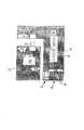
図3は図1と図2の一方または両者の特徴と共に使用する第1の実施形態を示している。ここでオーディオ装置112 は例えばMP3プレーヤ等のオーディオプレーヤである。図示されているのは音量制御装置10であるが、これはスピーカ装置210 であってもよい。装置10はノブ18により動作される主要な音量制御装置26を有する。制御装置26は入力ケーブル28によりポート14へ動作的に接続され、オーディオ信号をスピーカ装置(図示せず)に供給するための出力ケーブル30を有する。スピーカ装置からの電力供給ケーブル32はコネクタ116 がポート14と結合されるときパワーを装置112 へ与えるためにポート14に接続されている。これは装置112 の任意の独立した電源で不必要なドレインを防止する。接続されるとき、コネクタ116 からのパワーケーブル134 は装置112 を動作するために電力を装置112 へ供給する。オーディオ装置112 はケーブル152 を介してオーディオ信号をコネクタ116 へ供給するためにケーブル150 により出力信号をオーディオ装置の制御装置138 へ供給する不揮発性メモリ136 を有する。オーディオはその後、スピーカ装置で再生されることができる。 FIG. 3 illustrates a first embodiment for use with one or both of the features of FIGS. Here, the
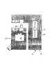
図4は、図1および図2の一方または両者の特徴を使用する第2の実施形態を示している。ここでオーディオ装置212 は例えばAM/FMチューナのようなオーディオチューナである。図示されているのは音量制御装置10であるが、これはスピーカ装置210 であってもよい。装置10はノブ18により動作される主要な音量制御装置26を有する。制御装置26は入力ケーブル28によりポート14へ動作的に接続され、オーディオ信号をスピーカ装置(図示せず)に供給するための出力ケーブル30を有する。スピーカ装置からの電力供給ケーブル32はコネクタ216 がポート214 と結合されるときパワーを装置212 へ与えるためにポート14に接続されている。これは装置212 の任意の独立した電源で不必要なドレインを防止する。接続されるとき、コネクタ216 からのパワーケーブル234 は装置212 を動作するため電力を装置212 へ供給する。オーディオ装置212 はケーブル252 によりオーディオ信号をコネクタ216 へ供給するためのAM/FMチューナ240 を有する。オーディオはその後、スピーカ装置で再生されることができる。ケーブル20のスリーブ42はAM/FMチューナ240 用のアンテナとして使用されてもよく、スリーブ42はポート14に接続され、コネクタ216 はアンテナ信号をAM/FMチューナ240 へ接続するためのアンテナケーブル244 を有する。 FIG. 4 illustrates a second embodiment that uses one or both of the features of FIGS. Here, the
図5は図1と図2の一方または両者の特徴を使用する第3の実施形態を示している。ここでオーディオ装置312 は無線信号をヘッドホン(またはそれに等価な装置)へ供給するための無線ヘッドホン送信機モジュールである。図示されているのは音量制御装置10であるが、これはスピーカ装置210 であってもよい。装置10はノブ18により動作される主要な音量制御装置26を有する。制御装置26は入力ケーブル28によりポート14へ動作的に接続され、オーディオ信号をスピーカ装置(図示せず)に供給するための出力ケーブル30を有する。スピーカ装置からの電力供給ケーブル32はコネクタ316 がポート14と結合されるときパワーを装置312 へ与えるためにポート14に接続されている。これは装置312 に対して任意の独立した電源で不必要なドレインを防止する。接続されるとき、コネクタ316 からのパワーケーブル334 は装置312 を動作するために電力を装置312 へ供給する。オーディオ装置312 は無線送信機348 がオーディオ信号をヘッドホン346 へ供給することを可能にするためにケーブル352 によりコネクタ316 からオーディオ入力信号を受信するための無線送信機348 を有する。オーディオはその後、ヘッドホン346 を使用して再生されることができる。 FIG. 5 shows a third embodiment using one or both of the features of FIGS. Here, the
図6は無線送信機448 からの出力がスピーカ装置(図示せず)へ送信される点を除いて図5の実施形態と全ての面で同一の第4の実施形態を示している。 FIG. 6 shows a fourth embodiment identical in all respects to the embodiment of FIG. 5 except that the output from the
図7はオーディオ信号をスピーカ装置(図示せず)へ供給するために(図6の送信機のような)無線送信機からの信号を受信するために無線受信機554 が設けられている点を除いて図5および図6の実施形態と全ての面で同一の第5の実施形態を示している。 FIG. 7 shows that a
図8は制御信号をスピーカ装置(図示せず)の音量制御装置626 と他の機能(例えばON/OFF、高音域、低音域、バランス等)へ供給するために無線送信機656 から制御を受信するための無線受信機654 点を除いて図7の実施形態と全ての面で同一の第6の実施形態を示している。これはスピーカ装置が容易に無線動作に変換されることを可能にする。 FIG. 8 illustrates receiving control from a
本発明の好ましい実施形態および特徴を前述のとおり説明したが、設計または構造の詳細についての多数の変形が本発明の技術的範囲を逸脱せずに行われることが当業者により理解されるであろう。 While the preferred embodiments and features of the invention have been described above, it will be appreciated by those skilled in the art that numerous modifications in the details of design or construction may be made without departing from the scope of the invention. Would.
本発明は個々および全ての可能な交換および組合わせの両者で説明された全ての特徴までの範囲である。 The invention extends to all features described in both individual and all possible exchanges and combinations.
Claims (16)
Translated fromJapanese前記装置とオーディオ装置との間に機能的な接続を可能にするためにオーディオ装置の第2のコネクタと電気接続するため装置上に第1のコネクタを有し、さらに、
(a)音響再生装置の機能を制御する制御装置と、
(b)電気パワーをオーディオ装置へ供給するための電気パワーコネクタと、
(c)制御装置とオーディオ装置との間に機能的な関係を設定するためにオーディオ装置と機能的に接続するための少なくとも1つの機能的接続とを含んでいる装置。An apparatus having a receptor for use with a sound reproducer and removably receiving the audio apparatus,
A first connector on the device for electrically connecting with a second connector of the audio device to allow a functional connection between the device and the audio device;
(A) a control device for controlling the function of the sound reproducing device;
(B) an electric power connector for supplying electric power to the audio device;
(C) a device comprising at least one functional connection for operatively connecting to the audio device to establish a functional relationship between the control device and the audio device.
前記装置とオーディオ装置との間に機能的な接続を可能にするためオーディオ装置の第2のコネクタと電気接続するように前記装置上に設置されている第1のコネクタを有し、さらに、
(a)音響再生装置の機能を制御できる第1の制御装置と、
(b)電気パワーをオーディオ装置へ供給するための電気パワーコネクタと、
(c)第1の制御装置とオーディオ装置との間に機能的な関係を設定するためのオーディオ装置との少なくとも1つの機能的な接続とを含んでいる装置。A device used with a sound reproducing device, wherein the audio device can be removably mounted;
A first connector located on the device to electrically connect with a second connector of the audio device to enable a functional connection between the device and the audio device;
(A) a first control device capable of controlling the function of the sound reproduction device;
(B) an electric power connector for supplying electric power to the audio device;
(C) at least one functional connection with the audio device for establishing a functional relationship between the first control device and the audio device.
Applications Claiming Priority (2)
| Application Number | Priority Date | Filing Date | Title |
|---|---|---|---|
| SG200206777 | 2002-11-08 | ||
| US10/323,347US20040091124A1 (en) | 2002-11-08 | 2002-12-17 | Audio devices |
Publications (1)
| Publication Number | Publication Date |
|---|---|
| JP2004166272Atrue JP2004166272A (en) | 2004-06-10 |
Family
ID=32228002
Family Applications (1)
| Application Number | Title | Priority Date | Filing Date |
|---|---|---|---|
| JP2003378414APendingJP2004166272A (en) | 2002-11-08 | 2003-11-07 | Audio system and improvement of the same |
Country Status (8)
| Country | Link |
|---|---|
| US (1) | US20040091124A1 (en) |
| EP (1) | EP1418791A3 (en) |
| JP (1) | JP2004166272A (en) |
| KR (1) | KR20040041046A (en) |
| CN (1) | CN1505439A (en) |
| AU (1) | AU2003278679A1 (en) |
| TW (1) | TW200414781A (en) |
| WO (1) | WO2004042880A1 (en) |
Cited By (2)
| Publication number | Priority date | Publication date | Assignee | Title |
|---|---|---|---|---|
| KR100796623B1 (en) | 2006-07-12 | 2008-01-22 | 네오피델리티 주식회사 | Detachable necklace-type sound reproduction device |
| CN108377440A (en)* | 2018-03-30 | 2018-08-07 | 郑州蓝奇盾网络科技有限公司 | A kind of computer speaker |
Families Citing this family (21)
| Publication number | Priority date | Publication date | Assignee | Title |
|---|---|---|---|---|
| US20040162029A1 (en)* | 2002-07-17 | 2004-08-19 | Jeff Grady | Audio player assembly comprising an MP3 player |
| US6591085B1 (en)* | 2002-07-17 | 2003-07-08 | Netalog, Inc. | FM transmitter and power supply/charging assembly for MP3 player |
| US20070086724A1 (en)* | 2002-07-17 | 2007-04-19 | Jeff Grady | Interface systems for portable digital media storage and playback devices |
| US7486637B2 (en) | 2002-09-26 | 2009-02-03 | Interdigital Technology Corporation | Wireless communication method and system for efficiently managing paging windows and data messages |
| TW200512991A (en)* | 2003-09-26 | 2005-04-01 | Hon Hai Prec Ind Co Ltd | Cable device for transmitting and receiving data |
| US7103194B2 (en)* | 2003-09-29 | 2006-09-05 | Hsia Ben M | Wall hanged audio arrangement |
| US7653344B1 (en)* | 2004-01-09 | 2010-01-26 | Neosonik | Wireless digital audio/video playback system |
| US20060082552A1 (en)* | 2004-10-18 | 2006-04-20 | Scythe Taiwan Co., Ltd. | Mouse with audio output function |
| EP1676574A3 (en) | 2004-12-30 | 2006-07-26 | Johnson & Johnson Vision Care, Inc. | Methods for promoting survival of transplanted tissues and cells |
| US7783065B2 (en)* | 2005-03-18 | 2010-08-24 | Nyko Technologies, Inc. | Wireless headphone kit for media players |
| US20060235551A1 (en)* | 2005-04-13 | 2006-10-19 | Creative Technology Ltd. | Data storage device with audio capability |
| US7469053B2 (en)* | 2005-04-15 | 2008-12-23 | Plantronics, Inc. | Stand system with integrated electrical plug for portable electronic devices |
| US20070015485A1 (en)* | 2005-07-14 | 2007-01-18 | Scosche Industries, Inc. | Wireless Media Source for Communication with Devices on Data Bus of Vehicle |
| US20070023228A1 (en)* | 2005-07-29 | 2007-02-01 | Yu-Shu Lin | Multifunction speaker cabinet |
| US8010728B1 (en) | 2005-11-07 | 2011-08-30 | Koninklijke Philips Electronics N.V. | Multi-function docking assembly for portable digital media storage and playback device |
| KR100788620B1 (en)* | 2006-12-12 | 2007-12-26 | 주식회사 대우아이에스 | Car audio |
| GB2447634A (en)* | 2007-03-23 | 2008-09-24 | Giga Byte Tech Co Ltd | Sound output device with earphone mode and speaker mode |
| EP2194438A1 (en)* | 2008-11-28 | 2010-06-09 | BRITISH TELECOMMUNICATIONS public limited company | Media adaptor |
| US20100198428A1 (en)* | 2009-01-30 | 2010-08-05 | Delphi Technologies, Inc. | Multi-purpose fob system |
| TWM427694U (en)* | 2011-12-06 | 2012-04-21 | Tuton Technology Co Ltd | Connector with sound playback module |
| US20130315416A1 (en)* | 2012-05-22 | 2013-11-28 | David Nakayama | Device connecting multiple audio sources over wireless connections to amplifiers and speakers |
Family Cites Families (13)
| Publication number | Priority date | Publication date | Assignee | Title |
|---|---|---|---|---|
| DE3139893A1 (en)* | 1980-10-09 | 1982-07-08 | Mitsubishi Denki K.K., Tokyo | PORTABLE ACOUSTIC DEVICE |
| US5147986A (en)* | 1990-12-03 | 1992-09-15 | Tandy Corporation | Subwoofer speaker system |
| JP3315131B2 (en)* | 1991-08-27 | 2002-08-19 | パイオニア株式会社 | Automotive electronics |
| US5831515A (en)* | 1995-02-17 | 1998-11-03 | Carson Maunfacturing Company, Inc. | Electronic siren apparatus including an integrated handheld microphone and control handle |
| IL118230A0 (en)* | 1995-05-25 | 1996-09-12 | Voquette Network Ltd | A vocal information system |
| JPH09191439A (en)* | 1996-01-08 | 1997-07-22 | Casio Comput Co Ltd | Small tv device |
| US5838537A (en)* | 1996-08-21 | 1998-11-17 | Gateway 2000, Inc. | Retractable speakers for portable computer |
| US6007228A (en)* | 1997-05-21 | 1999-12-28 | Neomagic Corp. | Master digital mixer with digital-audio links to external audio in a docking station and to internal audio inside a portable PC |
| GB2336701A (en)* | 1998-04-21 | 1999-10-27 | Polarmax Limited | Detachable function unit |
| DE19838636A1 (en)* | 1998-08-26 | 2000-03-02 | Basf Ag | Carotenoid formulations containing a mixture of beta-carotene, lycopene and lutein |
| JP4135287B2 (en)* | 2000-02-01 | 2008-08-20 | ソニー株式会社 | RECORDING / REPRODUCING DEVICE, PORTABLE DEVICE, DATA TRANSFER SYSTEM, DATA TRANSFER METHOD, DATA REPRODUCING METHOD, DATA TRANSFER AND REPRODUCING METHOD |
| US6937732B2 (en)* | 2000-04-07 | 2005-08-30 | Mazda Motor Corporation | Audio system and its contents reproduction method, audio apparatus for a vehicle and its contents reproduction method, portable audio apparatus, computer program product and computer-readable storage medium |
| US6873862B2 (en)* | 2001-07-24 | 2005-03-29 | Marc Alan Reshefsky | Wireless headphones with selective connection to auxiliary audio devices and a cellular telephone |
- 2002
- 2002-12-17USUS10/323,347patent/US20040091124A1/ennot_activeAbandoned
- 2003
- 2003-11-07WOPCT/SG2003/000258patent/WO2004042880A1/ennot_activeApplication Discontinuation
- 2003-11-07EPEP03257040Apatent/EP1418791A3/ennot_activeWithdrawn
- 2003-11-07JPJP2003378414Apatent/JP2004166272A/enactivePending
- 2003-11-07TWTW092131217Apatent/TW200414781A/enunknown
- 2003-11-07KRKR1020030078549Apatent/KR20040041046A/ennot_activeWithdrawn
- 2003-11-07CNCNA200310113301Apatent/CN1505439A/enactivePending
- 2003-11-07AUAU2003278679Apatent/AU2003278679A1/ennot_activeAbandoned
Cited By (2)
| Publication number | Priority date | Publication date | Assignee | Title |
|---|---|---|---|---|
| KR100796623B1 (en) | 2006-07-12 | 2008-01-22 | 네오피델리티 주식회사 | Detachable necklace-type sound reproduction device |
| CN108377440A (en)* | 2018-03-30 | 2018-08-07 | 郑州蓝奇盾网络科技有限公司 | A kind of computer speaker |
Also Published As
| Publication number | Publication date |
|---|---|
| CN1505439A (en) | 2004-06-16 |
| KR20040041046A (en) | 2004-05-13 |
| AU2003278679A1 (en) | 2004-06-07 |
| US20040091124A1 (en) | 2004-05-13 |
| WO2004042880A1 (en) | 2004-05-21 |
| TW200414781A (en) | 2004-08-01 |
| EP1418791A2 (en) | 2004-05-12 |
| EP1418791A3 (en) | 2007-06-27 |
Similar Documents
| Publication | Publication Date | Title |
|---|---|---|
| JP2004166272A (en) | Audio system and improvement of the same | |
| US10950215B2 (en) | Communication apparatus with ambient noise reduction | |
| TWI474724B (en) | Multimode audio reproduction device | |
| US8175304B1 (en) | Compact loudspeaker system | |
| US7803016B2 (en) | Electronic accessory for an MP3 player, and method of providing the same | |
| US20090175458A1 (en) | Subwoofer docking station | |
| US20030123690A1 (en) | Loudspeaker mounting system | |
| US8816182B2 (en) | Digital audio connections for portable handheld computing devices | |
| WO2018053498A1 (en) | Microphone system for direct coupling to recording devices | |
| US20120008801A1 (en) | "POSSE" -- an acronym for "Personal OnStage Sound Enhancer" | |
| US8484026B2 (en) | Portable audio control system and audio control device thereof | |
| KR100740164B1 (en) | Guitar amplifier | |
| KR20010008044A (en) | Portable multi-channel amplifier | |
| JP3975233B2 (en) | Audio equipment and audio output control method | |
| KR100403538B1 (en) | Digital surrounding audio system for personal computer | |
| JP3048252U (en) | Notebook computer | |
| KR200390263Y1 (en) | Portable Audio Amplifier And Portable Speaker System Comprising The Same | |
| KR100677335B1 (en) | How to operate external speaker holder of mobile communication terminal | |
| KR101323949B1 (en) | Personal computer having a Digtal amplifier module and the 5.1channel controlling method | |
| JPH1153054A (en) | Notebook-sized type personal computer auxiliary device | |
| KR200379009Y1 (en) | Kitchen radio phone with mp3 player | |
| KR200294563Y1 (en) | sound support device using FM transmitter | |
| KR200233581Y1 (en) | Portable multi-channel amplifier | |
| JP3068748U (en) | PC main unit with built-in ultra-low frequency speaker | |
| KR200235861Y1 (en) | Headphone and micset for music practice |