Movatterモバイル変換


[0]ホーム

URL:


JP2004161015A - Ink cartridge for inkjet recording device - Google Patents

Ink cartridge for inkjet recording device
Download PDF

Info

Publication number
JP2004161015A
JP2004161015AJP2004071189AJP2004071189AJP2004161015AJP 2004161015 AJP2004161015 AJP 2004161015AJP 2004071189 AJP2004071189 AJP 2004071189AJP 2004071189 AJP2004071189 AJP 2004071189AJP 2004161015 AJP2004161015 AJP 2004161015A
Authority
JP
Japan
Prior art keywords
ink cartridge
ink
lever
cartridge holder
main body
Prior art date
Legal status (The legal status is an assumption and is not a legal conclusion. Google has not performed a legal analysis and makes no representation as to the accuracy of the status listed.)
Granted
Application number
JP2004071189A
Other languages
Japanese (ja)
Other versions
JP4747503B2 (en
Inventor
Takero Seino
健朗 情野
Satoshi Shinada
聡 品田
Hisashi Miyazawa
久 宮澤
Yasuto Sakai
康人 坂井
Masaki Shimomura
正樹 下村
Satoshi Nakada
聡 中田
Current Assignee (The listed assignees may be inaccurate. Google has not performed a legal analysis and makes no representation or warranty as to the accuracy of the list.)
Seiko Epson Corp
Original Assignee
Seiko Epson Corp
Priority date (The priority date is an assumption and is not a legal conclusion. Google has not performed a legal analysis and makes no representation as to the accuracy of the date listed.)
Filing date
Publication date
Application filed by Seiko Epson CorpfiledCriticalSeiko Epson Corp
Priority to JP2004071189ApriorityCriticalpatent/JP4747503B2/en
Publication of JP2004161015ApublicationCriticalpatent/JP2004161015A/en
Application grantedgrantedCritical
Publication of JP4747503B2publicationCriticalpatent/JP4747503B2/en
Anticipated expirationlegal-statusCritical
Expired - Fee Relatedlegal-statusCriticalCurrent

Links

Images

Landscapes

Abstract

Translated fromJapanese

【課題】インク供給針に挿抜可能で、かつ長期間の外力の作用の有無に関わりなく、レバーの爪を確実にインクカートリッジホルダに係合させること。
【解決手段】容器本体にインクを収納するとともに、記録装置のインクカートリッジホルダに装着された状態で容器本体に連通するインク供給口を介して記録ヘッドにインクを供給するインクカートリッジ1において、容器本体を構成する面4、5に、インク供給口3の側を回動支点とするレバー50、51を形成するとともに、レバー50、51にインクカートリッジホルダと係脱可能な爪部56、57と、レバーの爪部56、57を支持する可倒な支柱52、53とを形成する。
【選択図】図6
An object of the present invention is to reliably engage a claw of a lever with an ink cartridge holder regardless of the presence or absence of a long-term external force that can be inserted into and removed from an ink supply needle.
An ink cartridge (1) for storing ink in a container main body and supplying ink to a recording head via an ink supply port communicating with the container main body while being attached to an ink cartridge holder of a recording apparatus. The levers 50 and 51 are formed on the surfaces 4 and 5 of which are formed with the ink supply port 3 as a fulcrum, and the levers 50 and 51 are provided with claw portions 56 and 57 capable of engaging and disengaging from the ink cartridge holder. Reversible supports 52, 53 for supporting the pawl portions 56, 57 of the lever are formed.
[Selection diagram] FIG.

Description

Translated fromJapanese

本発明は、インクジェット記録ヘッドを搭載したキャリッジにインクカートリッジを装着してインクを記録ヘッドに供給する記録装置に適したインクカートリッジに関する。  The present invention relates to an ink cartridge suitable for a recording apparatus in which an ink cartridge is mounted on a carriage having an ink jet recording head and ink is supplied to the recording head.

インクジェット記録ヘッドを備えたキャリッジに着脱可能にインク容器を搭載した記録装置にあっては、印刷時のキャリッジの移動による抜けを防止するとともに、外部操作により容易に係合が解除できる係止機構を備えている。
このような係止機構は、例えば特許文献1に見られるように、インクタンクの対向する2つの側面に一方にはインクカートリッジホルダに係合する凸部を、また他方の面には回動可能なレバーに爪を形成して、凸部をインクカートリッジホルダに係合させた状態で、凸部を回動支点とするように他方の面を移動させて爪をインクカートリッジホルダに係合させるように構成されている。
特開平10−44451号公報
In a recording apparatus in which an ink container is detachably mounted on a carriage having an ink jet recording head, a locking mechanism that prevents detachment due to movement of the carriage during printing and that can easily be disengaged by an external operation is provided. Have.
For example, as shown inPatent Literature 1, such a locking mechanism has a protrusion that engages with an ink cartridge holder on one of two opposing side surfaces of an ink tank and a rotatable one on the other surface. A pawl is formed on the lever, and the other surface is moved so that the protruding portion is used as a rotation fulcrum while the protruding portion is engaged with the ink cartridge holder, so that the pawl is engaged with the ink cartridge holder. Is configured.
JP-A-10-44451

しかしながら、インクカートリッジの回動により装着するものにあっては、記録ヘッドに連通するインク供給針を介してインク流路を形成するインク容器には適用が困難である。
すなわち、インク供給針は、インク容器との確実な連通を確保するため、所定の長さを有するから、軸方向以外の外力を受けると折損する虞があり、このため、インク容器をインク供給針の長さ方向に平行に移動させる必要がある。
また、特許文献2に見られるようにインクを収容する容器の対向する2つの面に、インクカートリッジホルダと係合する爪部を備えた弾性変形可能なレバーを形成してインク供給針に挿通可能としたインクカートリッジも提案されている。
また、特に大気等が溶存していないインクを必要とする記録装置、つまり圧電素子によりインクを加圧する記録ヘッドを搭載した記録装置にあっては、インクカートリッジを遮気性フィルムでできた袋に減圧状態で収容して保存されている。
このため、袋を介して作用する大気圧によりレバーが容器本体に強い力で押し付けられ、長期間の間にはレバーがクリープ変形して、固定部としての機能が失われるという問題がある。
本発明はこのような問題に鑑みてなされたものであって、その目的とするところは、インク供給針に挿抜可能で、かつ長期間の外力の作用の有無に関わりなく、レバーの爪を確実にインクカートリッジホルダに係合させることができるインクカートリッジを提供することである。
特開平9-11500号公報
However, it is difficult to apply an ink container that is mounted by rotating the ink cartridge to an ink container that forms an ink flow path via an ink supply needle that communicates with a recording head.
That is, since the ink supply needle has a predetermined length in order to ensure reliable communication with the ink container, the ink supply needle may be broken when subjected to an external force other than in the axial direction. Must be moved parallel to the length of
Further, as shown inPatent Document 2, an elastically deformable lever having a claw engaging with an ink cartridge holder is formed on two opposing surfaces of a container containing ink and can be inserted into an ink supply needle. Ink cartridges have also been proposed.
In particular, in the case of a recording device that requires ink in which the atmosphere or the like is not dissolved, that is, a recording device equipped with a recording head that pressurizes the ink by a piezoelectric element, the ink cartridge is decompressed into a bag made of an air-permeable film. It is stored and stored in a state.
For this reason, there is a problem that the lever is pressed against the container body by a strong force due to the atmospheric pressure acting through the bag, and the lever is creep-deformed for a long period of time, losing the function as the fixing portion.
The present invention has been made in view of such a problem, and an object of the present invention is to reliably insert and remove a lever claw regardless of whether or not an external force acts for a long time. To provide an ink cartridge that can be engaged with an ink cartridge holder.
JP-A-9-11500

このような問題を解消するために本発明においては、容器本体にインクを収納するとともに、記録装置のインクカートリッジホルダに装着された状態で前記容器本体に連通するインク供給口を介して記録ヘッドにインクを供給するインクカートリッジにおいて、
前記容器本体を構成する面に、前記インク供給口側を回動支点とするレバーを形成するとともに、前記レバーに前記インクカートリッジホルダと係脱可能な爪部と、前記レバーの爪部を支持する可倒な支柱とを形成して構成されている。
In order to solve such a problem, in the present invention, the ink is stored in the container main body, and the ink is supplied to the recording head through the ink supply port communicating with the container main body in a state of being mounted on the ink cartridge holder of the recording apparatus. In an ink cartridge for supplying ink,
A lever having the ink supply port side as a rotation fulcrum is formed on a surface constituting the container body, and the lever supports a claw portion detachable from the ink cartridge holder and a claw portion of the lever. It is configured by forming a resilient support.

本発明のインクカートリッジによれば、遮気性フィルムの袋に減圧状態で収容された状態でも、支柱によりレバーが過度に容器本体の側に押し付けられるのが防止される。
一方、インクカートリッジをホルダに装着する過程では支柱が押し倒されてレバーの爪部がホルダに係合してユーザにクリック感を与えて規定の位置まで移動したこと知らせる。
また、レバー自体の弾性に関わり無く、所定の強度で爪をインクカートリッジホルダに係合させた状態を維持させることができる。
ADVANTAGE OF THE INVENTION According to the ink cartridge of this invention, even if it is accommodated in the bag of an air-shielding film in a decompressed state, a lever prevents a lever from being pressed too much against a container main body side.
On the other hand, in the process of mounting the ink cartridge in the holder, the support is pushed down and the claw portion of the lever is engaged with the holder, giving a click feeling to the user to notify that the user has moved to the specified position.
Further, it is possible to maintain the state in which the claw is engaged with the ink cartridge holder with a predetermined strength regardless of the elasticity of the lever itself.

そこで以下に本発明の詳細を図示した実施例に基づいて説明する。
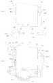
図1は、本発明のインクカートリッジの一実施例を示すものであって、インクカートリッジ1は、扁平な矩形状の容器本体2の下面に、容器本体2と連通してインク供給針に挿抜されるインク供給口3が形成され、また2つの側面4、5の上部に、インク供給口側、つまり下端を回動部6、7とするレバー8、9が形成されている。
Therefore, the details of the present invention will be described below based on the illustrated embodiment.
FIG. 1 shows an embodiment of the ink cartridge of the present invention. Theink cartridge 1 is inserted into and pulled out of an ink supply needle on the lower surface of a flatrectangular container body 2 in communication with thecontainer body 2. Anink supply port 3 is formed, andlevers 8 and 9 are formed above the twoside surfaces 4 and 5 with the ink supply port side, that is, the lower end as rotatingparts 6 and 7.

それぞれのレバー8、9の上端には把持部10、11が形成され、中間部には後述する記録装置のインクカートリッジホルダ30に係合する爪部12、13が形成され、さらには、回動部6、7と爪部12、13との中間には、インクカートリッジホルダ30のガイド部35、36に係合して拡開方向に付勢されるガイド用凸部14、15が形成されている。一方のガイド用凸部14は、下端側が若干先細りとなるように断面水滴型に形成され、また他方のガイド用凸部15は断面円形に形成されている。  Grip portions 10 and 11 are formed at the upper ends of therespective levers 8 and 9, andclaw portions 12 and 13 that engage with anink cartridge holder 30 of a recording apparatus described later are formed at an intermediate portion.Guide protrusions 14 and 15 which are engaged with theguide portions 35 and 36 of theink cartridge holder 30 and urged in the expanding direction are formed between theportions 6 and 7 and theclaw portions 12 and 13. I have. One of theguide projections 14 is formed in a water-drop cross section so that the lower end side is slightly tapered, and theother guide projection 15 is formed in a circular cross section.

また容器本体2の側面4、5の爪部12、13に対向する位置には、爪部12、13とインクカートリッジホルダ30との係合を解除できる程度にレバー8、9を容器本体2の側に移動可能とするストッパ用凸部16、17が形成されている。  Thelevers 8 and 9 of thecontainer body 2 are positioned at positions facing theclaw portions 12 and 13 on theside surfaces 4 and 5 of thecontainer body 2 to such an extent that the engagement between theclaw portions 12 and 13 and theink cartridge holder 30 can be released.Protrusions 16 and 17 for stopper that can move to the side are formed.

なお、この実施例においては、インクカートリッジ1の種類やインク量等のデータを格納した記憶手段20が、側面に装着されている。この記憶手段20は、表面となる側にインクカートリッジホルダ30の接点とコンタクトが可能な電極21が、また裏面には図示しない記憶素子を実装した回路基板22により構成されている。  In this embodiment, a storage means 20 storing data such as the type of theink cartridge 1 and the amount of ink is mounted on the side surface. The storage means 20 includes anelectrode 21 that can be in contact with a contact point of theink cartridge holder 30 on the front side, and acircuit board 22 on which a storage element (not shown) is mounted on the back side.

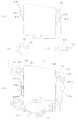
図2(イ)、(ロ)は記録ヘッド33及びインク供給針34からなるヘッドユニットを取り外した状態で上述したインクカートリッジ1が装着されるインクカートリッジホルダの一実施例を示すものであって、インクカートリッジホルダ30は、複数、この実施例では3つのリブ31により複数の領域に分割され、底面32には、図3に示したように記録ヘッド33と、これに連通するインク供給針34とからなるヘッドユニットが設けられ、インク供給針34がリブ31で分割された領域に配置されている。  FIGS. 2A and 2B show an embodiment of an ink cartridge holder in which the above-describedink cartridge 1 is mounted with the head unit including therecording head 33 and theink supply needle 34 removed. Theink cartridge holder 30 is divided into a plurality of regions by a plurality of, in this embodiment, threeribs 31, and abottom surface 32 includes arecording head 33 and anink supply needle 34 communicating therewith as shown in FIG. Is provided, and anink supply needle 34 is arranged in a region divided by therib 31.

各領域の上部にはインクカートリッジ1のガイド用凸部14、15が最初に当接する領域から、インク供給口3がインク供給針34に確実に装着される位置までガイド用凸部14、15が係合する溝や窓からなる垂直方向に延びるガイド部35、36が形成されている。ガイド部のうち、断面円形の凸部15が係合するガイド部36は、その上端の領域にレバー9の拡開状態に関わり無く挿入可能なように中央側に傾斜する斜面36aが形成されている。  At the top of each area, theguide projections 14, 15 from the area where theguide projections 14, 15 of theink cartridge 1 first contact to the position where theink supply port 3 is securely attached to theink supply needle 34 are provided. Vertically extendingguide portions 35 and 36, which are formed by engaging grooves and windows, are formed. Among the guide portions, theguide portion 36 with which theconvex portion 15 having a circular cross section is engaged has a slope 36a inclined toward the center side formed in the upper end region so that theguide portion 36 can be inserted regardless of the expanded state of thelever 9. I have.

この実施例において、インクカートリッジ1に収容されているインクの脱気度を維持するため、遮気性フィルムの袋に減圧状態で収容されている場合には、図4に示したようにレバー8、9が遮気性袋により容器本体2の側に大気圧により押圧され、容器本体2のストッパ用凸部16、17により支持されている。これにより、レバー8、9が過度に容器本体2の側に押し曲げられるのが防止される。  In this embodiment, in order to maintain the degree of deaeration of the ink stored in theink cartridge 1, when the ink is stored in the bag of the air-shielding film in a reduced pressure state, as shown in FIG. Thecontainer 9 is pressed against thecontainer body 2 by the air-tight bag by the atmospheric pressure, and is supported by thestopper projections 16 and 17 of thecontainer body 2. This prevents thelevers 8 and 9 from being excessively pushed and bent toward thecontainer body 2.

インクカートリッジ1を装着すべく袋から取り出された状態では、レバー8、9は、弾性により拡開するが、それでも長期間の間にはクリープ現象等により弾性を失ってレバー8、9はストッパ用凸部16、17に密着、もしくはそれに近い状態まで変形している可能性がある。  When theink cartridge 1 is taken out of the bag for mounting, thelevers 8 and 9 are expanded by elasticity. However, thelevers 8 and 9 still lose elasticity due to a creep phenomenon or the like for a long period of time, and thelevers 8 and 9 become stoppers. There is a possibility that theprojections 16 and 17 are deformed to a state close to or close to them.

このようなインクカートリッジ1は、レバー8、9を親指と人差し指で挟んで、装着時に奥側となる側面、この実施例では側面4をインクカートリッジホルダ30の壁30aに合わせて装着すると、この側面4に形成されているレバー8は、インクカートリッジホルダ30の壁30aとストッパ用凸部16とによりその位置を規制されるから、そのガイド用凸部14は可及的にガイド部35の近傍に位置し、かつその先細り形状によりガイド部35に進入する。またレバー9のガイド用凸部15は、ガイド部36の上部の斜面36aに沿って案内されてガイド部36に進入する。これにより、レバー8、9は回動部6、7を支点としてガイド部35、36により外側に移動されてストッパ用凸部16、17から離れる。
また、インクカートリッジホルダ30には、壁30aに垂直で、かつレバー8の幅に略一致する間隙を規制するように第2の壁30b、30cが形成されているため、インクカートリッジ1が挿入される過程において、レバー8が壁30b、30cにより幅方向の位置を規制されて規定の位置を移動する。
When such anink cartridge 1 is mounted by holding thelevers 8 and 9 between the thumb and the index finger and mounting the side surface, which is the back side when mounting, in this embodiment, theside surface 4 to the wall 30a of theink cartridge holder 30, The position of thelever 8 formed on thecartridge 4 is regulated by the wall 30a of theink cartridge holder 30 and thestopper projection 16, so that theguide projection 14 is as close to theguide 35 as possible. And enters theguide portion 35 due to its tapered shape. Theguide projection 15 of thelever 9 is guided along the upper slope 36 a of theguide 36 and enters theguide 36. As a result, thelevers 8 and 9 are moved outward by theguide portions 35 and 36 with thepivot portions 6 and 7 as fulcrums, and separated from the stopper convexportions 16 and 17.
Further, since the second walls 30b and 30c are formed in theink cartridge holder 30 so as to regulate a gap perpendicular to the wall 30a and substantially equal to the width of thelever 8, theink cartridge 1 is inserted. In the process, the position of thelever 8 in the width direction is regulated by the walls 30b and 30c, and moves to a prescribed position.

なお、インクカートリッジホルダ30には、それぞれの位置に適したインクカートリッジ1だけが装着できるように識別片39が形成されており、またインクカートリッジ1にはこれに対応する図示しない凹部が形成されていて、適合するインクカートリッジ1だけをさらなる移動を可能ならしめるように構成されている。  Theink cartridge holder 30 is formed with anidentification piece 39 so that only theink cartridge 1 suitable for each position can be mounted, and theink cartridge 1 has a corresponding recess (not shown). Therefore, only thecompatible ink cartridge 1 can be moved further.

さらにインクカートリッジ1を押し込むと、インクカートリッジ1のガイド用凸部14、15がインクカートリッジホルダ30のガイド部35、36に案内されて規定の位置に移動し、レバー8、9の爪部12、13の斜面12a、13aがインクカートリッジホルダ30の係合部37、38の上面に当接し、ここで押し込み抵抗が発生する。  When theink cartridge 1 is further pushed in, theguide projections 14 and 15 of theink cartridge 1 are guided to theguide portions 35 and 36 of theink cartridge holder 30 and move to a predetermined position, and theclaw portions 12 of thelevers 8 and 9 are moved. The slopes 12a, 13a of theabutment 13 come into contact with the upper surfaces of theengagement portions 37, 38 of theink cartridge holder 30, where a pushing resistance is generated.

この状態で更にインクカートリッジ1を押し込むと、図5に示したようにレバー8、9の爪部12、13がその斜面12a、13aにより係合部37、38を乗り越え、係合部37、38の下面に落ち込む。このとき、開放されたレバー8、9の弾性エネルギによりユーザにクリック感を与える。これによりユーザは、インクカートリッジ1が規定の位置まで移動したことを感知し、それ以上の無用な押し込みを中止する。  When theink cartridge 1 is further pushed in in this state, as shown in FIG. 5, theclaw portions 12, 13 of thelevers 8, 9 get over theengaging portions 37, 38 by their slopes 12a, 13a, and theengaging portions 37, 38 Falls on the underside of. At this time, a click feeling is given to the user by the elastic energy of the openedlevers 8 and 9. As a result, the user senses that theink cartridge 1 has moved to the prescribed position, and stops further unnecessary pushing.

インクカートリッジホルダ30に装着されている状態では、インクカートリッジ1は、そのレバー8、9がガイド部35、36により常時外側に付勢された状態となっているから、若干の外力がレバー8、9に作用しても係合状態が維持される。  When theink cartridge 1 is mounted on theink cartridge holder 30, thelevers 8 and 9 of theink cartridge 1 are constantly urged outward by theguide portions 35 and 36. Even if it acts on 9, the engagement state is maintained.

一方、インクカートリッジ1のインクが消費され尽くした場合には、2本のレバー8、9を親指と人差し指とで挟むと、レバー8、9がガイド部35、36に支持されたガイド用凸部14、15を支点として弾性変形して爪部12、13がインクカートリッジホルダ30の係合部37、38よりも内側に移動する。この状態でレバー8、9を引き上げると、インク供給口3がインク供給針34から抜け、インクカートリッジ1をインクカートリッジホルダ30から取出すことができる。
なお、上述の実施例においてはインクカートリッジ1に2本のレバー8、9を設け、これら2本のレバー8、9をインクカートリッジホルダ30に係合させるようにしているが、少なくとも記憶手段20が設けられている側ののみレバー8を設けてインクカートリッジホルダ30に係合させれば、インクカートリッジ1とインク供給針34との結合状態を維持し、かつ記憶手段20の電極21をインクカートリッジホルダ30の接点に確実に接触させてコンタクトをも維持することができる。
On the other hand, when the ink in theink cartridge 1 is exhausted, when the twolevers 8 and 9 are sandwiched between the thumb and the index finger, thelevers 8 and 9 are guided by the guide protrusions supported by theguide portions 35 and 36. Theclaws 12 and 13 are elastically deformed with thefulcrums 14 and 15 as fulcrums, so that theclaws 12 and 13 move inward of theengagement portions 37 and 38 of theink cartridge holder 30. When thelevers 8 and 9 are pulled up in this state, theink supply port 3 comes off from theink supply needle 34, and theink cartridge 1 can be taken out from theink cartridge holder 30.
In the embodiment described above, twolevers 8 and 9 are provided on theink cartridge 1 and these twolevers 8 and 9 are engaged with theink cartridge holder 30, but at least the storage means 20 If thelever 8 is provided only on the side provided and engaged with theink cartridge holder 30, the connection state between theink cartridge 1 and theink supply needle 34 is maintained, and theelectrode 21 of the storage means 20 is connected to the ink cartridge holder. The contact can be maintained by reliably contacting the 30 contacts.

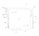
図6(イ)乃至〜(ハ)は、本発明のインクカートリッジの他の実施例を示すものであって、容器本体2の側面4、5に形成されたレバー50、51の爪部56、57は、レバー50、51の背面にあるレバー50、51から伸びた支柱52、53により容器本体2の側面4、5と適当な間隔を維持できるように支持されている。
支柱52、53の先端が当接する容器本体2の側面4、5には半円状の突起54、55が形成されている。
FIGS. 6A to 6C show another embodiment of the ink cartridge of the present invention, in which theclaw portions 56 of thelevers 50 and 51 formed on the side surfaces 4 and 5 of thecontainer body 2 are shown. 57 is supported bycolumns 52, 53 extending from thelevers 50, 51 on the back of thelevers 50, 51 so as to maintain an appropriate distance from the side surfaces 4, 5 of thecontainer body 2.
Semicircular projections 54 and 55 are formed on the side surfaces 4 and 5 of thecontainer body 2 with which the tips of thecolumns 52 and 53 abut.

この実施例によれば、工場出荷時に支柱52、53を半円状の突起54、55に係合させた状態で、インクカートリッジ1を遮気性フィルムの袋に減圧状態で収容すると、支柱52、53が側面4、5に対してほぼ垂直に保持されるので、レバー50、51の爪部56、57付近が過度に容器本体2の側に押し付けられるのが防止される。  According to this embodiment, when theink cartridge 1 is housed in a bag of an air-tight film under reduced pressure with theposts 52, 53 engaged with thesemicircular protrusions 54, 55 at the time of factory shipment, theposts 52, 53 Since the 53 is held substantially perpendicular to the side surfaces 4 and 5, the vicinity of theclaw portions 56 and 57 of thelevers 50 and 51 is prevented from being excessively pressed against thecontainer body 2.

一方、インクカートリッジ1をインクカートリッジホルダ30に押し込むと、図6(ニ)に示すように挿入の過程で、インクカートリッジホルダ30側に設けられた支持解除用突起40、41がインクカートリッジ1の支柱52、53を押し上げる。これにより支柱52、53は、先端が半円状の突起54、55を乗り越えて倒される。  On the other hand, when theink cartridge 1 is pushed into theink cartridge holder 30, thesupport release projections 40 and 41 provided on theink cartridge holder 30 side during the insertion process as shown in FIG. Push up 52 and 53. As a result, thepillars 52 and 53 fall over theprojections 54 and 55 having the semicircular tips.

この状態で更にインクカートリッジ1を押し込むと、レバー50、51は支柱52、53の支持を失っているから、その爪部56、57がその斜面56a、57aにより係合部37、38を乗り越え、係合部37、38の下面に落ち込む。このとき、開放されたレバー50、51の弾カエネルギによりユーザにクリック感を与える。これによりユーザはインクカートリッジ1が規定の位置まで移動したことを感知し、それ以上の無用な押し込みを中止する。  When theink cartridge 1 is further pushed in in this state, thelevers 50 and 51 lose the support of thecolumns 52 and 53, and theclaws 56 and 57 climb over the engagingportions 37 and 38 by the slopes 56a and 57a. It falls into the lower surface of the engagingparts 37 and 38. At this time, a click feeling is given to the user by the energy of the released levers 50 and 51. As a result, the user senses that theink cartridge 1 has moved to the prescribed position, and stops further unnecessary pushing.

図7(イ)乃至(ハ)は、レバー60、61の爪部66、67の背面の支柱62、63を、容器本体2に一体に形成した本発明のインクカートリッジの他の実施例を示すものである。
容器本体2の側面4、5には、レバー60、61の爪部66、67の近傍に対向するように回動可能な支柱62、63が形成され、またレバー60、61の容器本体2の側面4、5に対向する側の、爪部66、67の背面には半円状の突起64、65が形成されている。
FIGS. 7A to 7C show another embodiment of the ink cartridge of the present invention in which thesupport columns 62, 63 on the back surfaces of theclaws 66, 67 of thelevers 60, 61 are formed integrally with thecontainer body 2. FIG. Things.
On the side surfaces 4 and 5 of thecontainer body 2,columns 62 and 63 that can rotate so as to face the vicinity of theclaw portions 66 and 67 of thelevers 60 and 61 are formed.Semicircular projections 64 and 65 are formed on the back surfaces of theclaws 66 and 67 on the side facing the side surfaces 4 and 5.

この実施例によれば、工場出荷時に支柱62、63の自由端側をレバー60、61の半円状の突起64、65に係合させた状態で、インクカートリッジ1を遮気性フィルムの袋に減圧状態で収容すると、支柱62、63が側面4、5に対してほぼ垂直に保持されるので、レバー60、61の爪部66、67付近が過度に容器本体2の側に押し付けられるのが防止される。  According to this embodiment, when the free ends of thecolumns 62, 63 are engaged with thesemicircular projections 64, 65 of thelevers 60, 61 at the time of shipment from the factory, theink cartridge 1 is placed in the bag of the air-tight film. When stored in a decompressed state, thecolumns 62, 63 are held substantially perpendicular to the side surfaces 4, 5, so that the vicinity of theclaws 66, 67 of thelevers 60, 61 is excessively pressed against thecontainer body 2. Is prevented.

一方、インクカートリッジ1をインクカートリッジホルダ30に押し込むと、図7(ニ)に示すように挿入の過程で、インクカートリッジホルダ30側に設けられた支持解除用突起42、43がインクカートリッジ1の支柱62、63を押し上げる。これにより支柱62、63は、先端が半円状の突起64、65を乗り越えて倒される。  On the other hand, when theink cartridge 1 is pushed into theink cartridge holder 30, thesupport release projections 42 and 43 provided on theink cartridge holder 30 side during the insertion process as shown in FIG. Push up 62, 63. As a result, thepillars 62 and 63 fall over thesemicircular projections 64 and 65, respectively.

この状態で更にインクカートリッジ1を押し込むと、レバー60、61は、支柱62、63の支持を失っているから、爪部66、67がその斜面66a、67aにより係合部37、38を乗り越え、係合部37、38の下面に落ち込む。このとき、開放されたレバー60、61の弾カエネルギによりユーザにクリック感を与える。これによりユーザはインクカートリッジ1が規定の位置まで移動したことを感知し、それ以上の無用な押し込みを中止する。  When theink cartridge 1 is further pushed in in this state, thelevers 60, 61 have lost support of thecolumns 62, 63, and theclaws 66, 67 climb over the engagingportions 37, 38 by their slopes 66a, 67a. It falls into the lower surface of the engagingparts 37 and 38. At this time, a click feeling is given to the user by the energy of the released levers 60 and 61. As a result, the user senses that theink cartridge 1 has moved to the prescribed position, and stops further unnecessary pushing.

図8(イ)は本発明のインクカートリッジの他の実施例を示すものであって、容器本体2の側面4、5に形成されたレバー70、71は、下端がフリーとされていて中央部で支柱72、73により回動可能に支持され、支柱72、73より下部には短いリブ74、75が形成されている。  FIG. 8A shows another embodiment of the ink cartridge of the present invention, in which levers 70 and 71 formed on the side surfaces 4 and 5 of thecontainer body 2 have lower ends free and a central portion. Are rotatably supported by thecolumns 72, 73, andshort ribs 74, 75 are formed below thecolumns 72, 73.

この実施例によれば、インクカートリッジ1を遮気性フィルムの袋に減圧状態で収容した場合、レバー70、71の把持部78、79側は、容器本体2側に押し付けられて大きく変形するものの、リブ74、75は、短く剛性が大きいためほとんどクリープ変形しない。  According to this embodiment, when theink cartridge 1 is accommodated in a bag of an air-permeable film in a decompressed state, thegrips 78 and 79 of thelevers 70 and 71 are pressed against thecontainer body 2 and greatly deformed. Since theribs 74 and 75 are short and have high rigidity, they hardly undergo creep deformation.

インクカートリッジ1をインクカートリッジホルダ30に押し込むと、図8(ロ)に示すようにレバー70、71のリブ74、75が最初にインクカートリッジホルダ30に設けられた側壁44、45に当接かつ規制されて支柱72、73のつけ根を回動支点として回動して略垂直に起立する。
これにより、たとえ把持部78、79がクリープ変形していても、爪部76、77がインクカートリッジホルダ30の係合部37、38よりも外側に位置する。
When theink cartridge 1 is pushed into theink cartridge holder 30, theribs 74, 75 of thelevers 70, 71 abut and regulate theside walls 44, 45 first provided on theink cartridge holder 30 as shown in FIG. As a result, thesupport rods 72 and 73 are rotated about the bases of thesupport pillars 72 and 73 as a rotation fulcrum and stand substantially vertically.
As a result, even if thegrip portions 78 and 79 are creep-deformed, theclaw portions 76 and 77 are located outside theengagement portions 37 and 38 of theink cartridge holder 30.

したがって、インクカートリッジ1を遮気性フィルムの袋に減圧状態で収容した場合の、レバー70、71の把時部78、79の側が、容器本体2の側へたとえクリープ変形したとしても、爪部76、77を確実に係合部37、38の下部に当接させることができる。その結果、この弾性エネルギによりユーザにクリック感を与える。これによりユーザはインクカートリッジ1が規定の位置まで移動したことを感知し、それ以上の無用な押し込みを中止する。  Therefore, when theink cartridge 1 is housed in a bag of an air-shielding film in a reduced pressure state, even if thegripping portions 78, 79 of thelevers 70, 71 are creep-deformed toward thecontainer body 2, theclaw portions 76 are provided. , 77 can reliably contact the lower portions of theengagement portions 37, 38. As a result, a click feeling is given to the user by the elastic energy. As a result, the user senses that theink cartridge 1 has moved to the prescribed position, and stops further unnecessary pushing.

図9は、本発明のインクカートリッジ1の他の実施例を示すものであって、この実施例においては、容器本体2の表面、また裏面からレバー80、81の爪部86、87の近傍に突出するように耳部82、83を形成し、耳部82、83のレバー80、81に対向する側で、かつレバー80、81の外側に位置するように支柱84、85が形成されている。  FIG. 9 shows another embodiment of theink cartridge 1 of the present invention. In this embodiment, theink cartridge 1 is located near theclaw portions 86 and 87 of thelevers 80 and 81 from the front surface and the back surface of thecontainer body 2.Ears 82 and 83 are formed so as to protrude, andcolumns 84 and 85 are formed so as to be located on the sides of theears 82 and 83 facing thelevers 80 and 81 and outside thelevers 80 and 81. .

この実施例によれば、カートリッジ1を遮気性フィルムの袋に減圧状態で収容した場合にレバー80、81は、前述したようにストッパ用凸部16、17により支持されて容器本体2の側へのクリープ変形が防止され、また耳部82、83の支柱84、85により無用な拡開も防止できる。
すなわち、耳部82、83、及び支柱84、85がレバー80、81の保護部材として機能するから、爪部86、87が他のものに衝突して変形するのを防止して、インクカートリッジホルダ30との確実な係合を保証することができる。
According to this embodiment, when thecartridge 1 is housed in a bag of an air-permeable film under reduced pressure, thelevers 80 and 81 are supported by thestopper projections 16 and 17 and move toward thecontainer body 2 as described above. Is prevented, and unnecessarily widening can be prevented by thecolumns 84 and 85 of theears 82 and 83.
That is, since theear portions 82, 83 and thesupport columns 84, 85 function as protection members for thelevers 80, 81, theclaw portions 86, 87 are prevented from colliding with other members and deformed, and the ink cartridge holder A secure engagement with 30 can be guaranteed.

図10は、本発明の他の実施例を示すものであって、容器本体2に回動可能に形成されたレバー90、91の、少なくとも一方、つまり記憶手段20が設けられている面のレバー90の、容器本体2の側の面の、可及的上端、つまり移動側に位置するように支柱92を形成したものである。  FIG. 10 shows another embodiment of the present invention, in which at least one of thelevers 90 and 91 rotatably formed on thecontainer body 2, that is, the lever on the surface on which the storage means 20 is provided. Thestrut 92 is formed so as to be located at the upper end as much as possible, that is, on the moving side of the surface of thecontainer 90 on the side of thecontainer body 2.

この実施例によれば、インクカートリッジ1を遮気性フィルムの袋に減圧状態で収容しても、レバー90はその上端を支柱92に支持されて、クリープ変形を防止されるため、インクカートリッジホルダ30に装着した際にも、少なくともレバー90がクリープ変形していないため、ストッパ用凸部16により外側に弾性変形して爪部93がインクカートリッジホルダ30の係合部37に確実に係合する。
これにより、記憶手段20の電極21がインクカートリッジホルダ30の接点に確実に接触し、コンタクト関係を維持することができる。
According to this embodiment, even if theink cartridge 1 is housed in a bag of an air-permeable film under reduced pressure, thelever 90 has its upper end supported by thesupport 92 to prevent creep deformation. Even when theink cartridge holder 30 is mounted, at least thelever 90 is not creep-deformed, so that the stopperconvex portion 16 elastically deforms outward and theclaw portion 93 is securely engaged with the engagingportion 37 of theink cartridge holder 30.
As a result, theelectrodes 21 of the storage means 20 reliably contact the contacts of theink cartridge holder 30, and the contact relationship can be maintained.

図(イ)乃至(ハ)は、それぞれ本発明のインクカートリッジの一実施例を示す上面図、正面図、及び側面図である。FIGS. 1A to 1C are a top view, a front view, and a side view, respectively, showing an embodiment of the ink cartridge of the present invention.図(イ)、(ロ)は、それぞれ同上インクカートリッジに適した記録装置のインクカートリッジホルダの一実施例を示す斜視図である。FIGS. 3A and 3B are perspective views showing an embodiment of an ink cartridge holder of a recording apparatus suitable for the above ink cartridge.同上インクカートリッジホルダの一実施例を示す断面図である。FIG. 3 is a cross-sectional view illustrating an embodiment of the ink cartridge holder according to the present invention.同上インクカートリッジが遮気性袋に収容されている状態を示す図である。FIG. 3 is a diagram illustrating a state where the ink cartridge is housed in an air-tight bag.図(イ)は、同上インクカートリッジをインクカートリッジホルダに装着した状態を示す図であり、また図(ロ)、(ハ)は、ガイド部の近傍を拡大して示す図である。FIG. 2A is a diagram showing a state where the ink cartridge is mounted on the ink cartridge holder, and FIGS. 2B and 2C are diagrams showing the vicinity of the guide portion in an enlarged manner.図(イ)は、本発明のインクカートリッジの他の実施例を、遮気性袋から取り出された状態で示す図、図(ロ)、(ハ)は、それぞれ同上インクカートリッジの支柱近傍を拡大して示す図、及び図(ニ)はインクカートリッジホルダに装着された状態を示す図である。Fig. (A) is a view showing another embodiment of the ink cartridge of the present invention in a state where it is taken out of the air-tight bag, and Figs. (B) and (C) are enlarged views of the vicinity of the support of the ink cartridge, respectively. (D) is a view showing a state where the ink cartridge is mounted on the ink cartridge holder.図(イ)は、本発明のインクカートリッジの他の実施例を、遮気性袋から取り出された状態で示す図、図(ロ)、(ハ)は、それぞれ同上インクカートリッジの支柱近傍を拡大して示す図、及び図(ニ)はインクカートリッジホルダに装着された状態を示す図である。Fig. (A) is a view showing another embodiment of the ink cartridge of the present invention in a state where it is taken out of the air-tight bag, and Figs. (B) and (C) are enlarged views of the vicinity of the support of the ink cartridge, respectively. (D) is a view showing a state where the ink cartridge is mounted on the ink cartridge holder.図(イ)は、本発明のインクカートリッジの他の実施例を、遮気性袋から取り出された状態で示す図、及び図(ロ)はインクカートリッジホルダに装着された状態を示す図である。FIG. (A) is a view showing another embodiment of the ink cartridge of the present invention in a state where it is taken out of an air-permeable bag, and FIG. (B) is a view showing a state where the ink cartridge is mounted on an ink cartridge holder.図(イ)乃至(ハ)は、それぞれ本発明のインクカートリッジの他の実施例を示す上面図、正面図、及び側面図である。FIGS. 7A to 7C are a top view, a front view, and a side view, respectively, showing another embodiment of the ink cartridge of the present invention.本発明のインクカートリッジの他の実施例を示す斜視図である。FIG. 9 is a perspective view illustrating another embodiment of the ink cartridge of the present invention.

符号の説明Explanation of reference numerals

1 インクカートリッジ 2 容器本体 3 インク供給口 4、5 側面 6、7 回動部 8、9、50、51、60、61、70、71、80、81、90、91 レバー 10、11、78、79 把持部 12、13、56、57、66、67、76、77、86、87、93 爪部 14、15 ガイド用凸部 16、17 ストッパ用凸部 30 インクカートリッジホルダ 33 記録ヘッド 34 インク供給針 35、36 ガイド部 37、38 係合部 40、41、42、43 支持解除用突起 52、53、62、63、72、73、92 支柱  DESCRIPTION OFSYMBOLS 1Ink cartridge 2 Containermain body 3Ink supply port 4, 5Side surface 6, 7Rotating part 8, 9, 50, 51, 60, 61, 70, 71, 80, 81, 90, 91Lever 10, 11, 78, 79 Grippingportion 12, 13, 56, 57, 66, 67, 76, 77, 86, 87, 93Claw portion 14, 15 Guideconvex portion 16, 17 Stopperconvex portion 30Ink cartridge holder 33Recording head 34Ink supply Needle 35, 36Guide part 37, 38Engagement part 40, 41, 42, 43Support release projection 52, 53, 62, 63, 72, 73, 92 Prop

Claims (8)

Translated fromJapanese
容器本体にインクを収納するとともに、記録装置のインクカートリッジホルダに装着された状態で前記容器本体に連通するインク供給口を介して記録ヘッドにインクを供給するインクカートリッジにおいて、
前記容器本体を構成する面に、前記インク供給口側を回動支点とするレバーを形成するとともに、前記レバーに前記インクカートリッジホルダと係脱可能な爪部と、前記レバーの爪部を支持する可倒な支柱とを形成してなるインクカートリッジ。
An ink cartridge for storing ink in a container main body and supplying ink to a recording head via an ink supply port communicating with the container main body in a state where the ink cartridge is mounted on an ink cartridge holder of a recording apparatus.
A lever having the ink supply port side as a rotation fulcrum is formed on a surface constituting the container body, and the lever supports a claw portion detachable from the ink cartridge holder and a claw portion of the lever. An ink cartridge formed with a collapsed support.
前記可倒な支柱が、前記容器本体を構成する壁面に形成されている請求項1に記載のインクカートリッジ。  The ink cartridge according to claim 1, wherein the collapsible support is formed on a wall surface forming the container body. インクを収容する容器本体を構成する面に、前記インク供給口側を回動支点とするレバーを形成するとともに、前記レバーに爪部と、前記レバーの爪部を支持する可倒な支柱とを形成してなるインクカートリッジからインクの供給を受けるインクジェット記録装置において、
前記インクカートリッジが装着されるインクカートリッジホルダに、前記支柱に突き当り、前記支柱を回動させて押し倒す突起部が形成されているインクジェット記録装置。
On the surface constituting the container main body for storing ink, a lever having the ink supply port side as a rotation fulcrum is formed, and the lever is provided with a claw portion and a collapsible support for supporting the claw portion of the lever. In an ink jet recording apparatus receiving supply of ink from an ink cartridge formed,
An ink jet recording apparatus in which an ink cartridge holder in which the ink cartridge is mounted is provided with a protrusion that abuts against the support and turns the support to push down.
容器本体にインクを収納するとともに、記録装置のインクカートリッジホルダに装着された状態で前記容器本体に連連するインク供給口を介して記録ヘッドにインクを供給するインクカートリッジにおいて、
前記容器本体を構成する面に、中央部に回動支点となる支柱を備えたレバーを形成するとともに、前記レバーに前記インクカートリッジホルダと係脱可能な爪部を形成してなるインクカートリッジ。
An ink cartridge that stores ink in a container main body and supplies ink to a recording head via an ink supply port connected to the container main body in a state where the ink cartridge is mounted on an ink cartridge holder of a recording apparatus.
An ink cartridge comprising: a lever provided on a surface constituting the container main body; the lever having a support at a central portion serving as a rotation fulcrum; and a claw portion detachable from the ink cartridge holder formed on the lever.
インクを収容する容器本体を構成する面に、中央部に回動支点となる支柱を備えたレバーを形成するとともに、前記レバーに爪部を形成してなるインクカートリッジからインクの供給を受けるインクジェット記録装置において、
前記インクカートリッジが装着されるインクカートリッジホルダに、前記支柱の下部領域に当接する面が形成されているインクジェット記録装置。
Inkjet recording receiving ink supply from an ink cartridge having a lever provided with a post serving as a rotation fulcrum at the center on a surface constituting a container main body containing ink, and having a claw portion formed on the lever. In the device,
An ink jet recording apparatus in which an ink cartridge holder in which the ink cartridge is mounted has a surface formed in contact with a lower region of the support.
前記レバーの側面をカバーする耳部を前記容器本体に形成するとともに、前記耳部に前記レバーの外側への拡開を規制する支柱からなる保護部材が設けられている請求項1、2、4のいずれかに記載のインクカートリッジ。  5. An ear portion for covering the side surface of the lever is formed on the container body, and the ear portion is provided with a protection member comprising a column for restricting the lever from expanding outward. The ink cartridge according to any one of the above. 前記レバーの、前記容器本体に対向する面の移動側に支柱が形成されている請求項1、2、4、6のいずれかに記載のインクカートリッジ。  7. The ink cartridge according to claim 1, wherein a support is formed on a moving side of a surface of the lever facing the container body. 前記レバーが、前記容器を構成し、かつ対向する2つの面に形成されている請求項1、2、4、6、7のいずれかに記載のインクカートリッジ。  The ink cartridge according to any one of claims 1, 2, 4, 6, and 7, wherein the lever forms the container and is formed on two opposing surfaces.
JP2004071189A2001-04-032004-03-12 Ink cartridge for ink jet recording apparatusExpired - Fee RelatedJP4747503B2 (en)

Priority Applications (1)

Application NumberPriority DateFiling DateTitle
JP2004071189AJP4747503B2 (en)2001-04-032004-03-12 Ink cartridge for ink jet recording apparatus

Applications Claiming Priority (5)

Application NumberPriority DateFiling DateTitle
JP20011045262001-04-03
JP20012063422001-07-06
JP2004071189AJP4747503B2 (en)2001-04-032004-03-12 Ink cartridge for ink jet recording apparatus

Related Parent Applications (1)

Application NumberTitlePriority DateFiling Date
JP2001263779ADivisionJP3582592B2 (en)1990-08-162001-08-31 Ink cartridge and inkjet recording device

Publications (2)

Publication NumberPublication Date
JP2004161015Atrue JP2004161015A (en)2004-06-10
JP4747503B2 JP4747503B2 (en)2011-08-17

Family

ID=32830457

Family Applications (1)

Application NumberTitlePriority DateFiling Date
JP2004071189AExpired - Fee RelatedJP4747503B2 (en)2001-04-032004-03-12 Ink cartridge for ink jet recording apparatus

Country Status (1)

CountryLink
JP (1)JP4747503B2 (en)

Citations (3)

* Cited by examiner, † Cited by third party
Publication numberPriority datePublication dateAssigneeTitle
JPH0911500A (en)*1995-06-291997-01-14Brother Ind Ltd Ink cartridge mounting structure
JPH0958006A (en)*1995-08-261997-03-04Seiko Epson Corp Ink cartridge loading device for printer
JPH1095129A (en)*1996-07-311998-04-14Canon Inc Liquid storage container for inkjet recording device

Patent Citations (3)

* Cited by examiner, † Cited by third party
Publication numberPriority datePublication dateAssigneeTitle
JPH0911500A (en)*1995-06-291997-01-14Brother Ind Ltd Ink cartridge mounting structure
JPH0958006A (en)*1995-08-261997-03-04Seiko Epson Corp Ink cartridge loading device for printer
JPH1095129A (en)*1996-07-311998-04-14Canon Inc Liquid storage container for inkjet recording device

Also Published As

Publication numberPublication date
JP4747503B2 (en)2011-08-17

Similar Documents

PublicationPublication DateTitle
JP3582592B2 (en) Ink cartridge and inkjet recording device
KR100255738B1 (en)Input pen accomodation mechanism for tablet input apparatus
JP3867802B2 (en) ink cartridge
JP2008207567A (en) Inkjet recording device
JP2002167084A (en) Cartridge holding device and tape printer having the same
JPS63274555A (en) inkjet printer
EP1281530A3 (en)Pivoting on-axis ink reservoir for inkjet printer
JP2004161015A (en) Ink cartridge for inkjet recording device
JP5188917B2 (en) Connector and jig
US6708613B2 (en)Elongated stamping device
JP2002337358A (en) ink cartridge
KR0126866Y1 (en) Head storage container of ink jet printer
HK1071331A (en)Ink cartridge and ink-jet recording apparatus
JPS61249757A (en) How to recover an inkjet cartridge
JP2006281793A (en) Ink cartridge and ink jet recording apparatus
HK1080802A (en)Ink cartridge and ink-jet recording apparatus
JPH0852282A (en)Cartridge type cutter knife
KR200267703Y1 (en) Clip-type pen lead device of writing instruments
KR200361501Y1 (en)Scraper
EP2039522B1 (en)Ink cartridge assembly
JP2002283695A (en) Stamp unit and stamp stand
JP2004174905A (en) Containers and holders for recording devices
JP2004175000A (en) Inkjet recording device
KR20050106995A (en)Scraper
KR20010077750A (en)Automatic writing apparatus for segmental writing elements with caps

Legal Events

DateCodeTitleDescription
RD04Notification of resignation of power of attorney

Free format text:JAPANESE INTERMEDIATE CODE: A7424

Effective date:20071220

RD03Notification of appointment of power of attorney

Free format text:JAPANESE INTERMEDIATE CODE: A7423

Effective date:20071227

A621Written request for application examination

Free format text:JAPANESE INTERMEDIATE CODE: A621

Effective date:20080801

A131Notification of reasons for refusal

Free format text:JAPANESE INTERMEDIATE CODE: A131

Effective date:20101026

A521Written amendment

Free format text:JAPANESE INTERMEDIATE CODE: A523

Effective date:20101221

A131Notification of reasons for refusal

Free format text:JAPANESE INTERMEDIATE CODE: A131

Effective date:20110118

A521Written amendment

Free format text:JAPANESE INTERMEDIATE CODE: A523

Effective date:20110318

A01Written decision to grant a patent or to grant a registration (utility model)

Free format text:JAPANESE INTERMEDIATE CODE: A01

Effective date:20110419

A61First payment of annual fees (during grant procedure)

Free format text:JAPANESE INTERMEDIATE CODE: A61

Effective date:20110502

R150Certificate of patent or registration of utility model

Free format text:JAPANESE INTERMEDIATE CODE: R150

FPAYRenewal fee payment (event date is renewal date of database)

Free format text:PAYMENT UNTIL: 20140527

Year of fee payment:3

S531Written request for registration of change of domicile

Free format text:JAPANESE INTERMEDIATE CODE: R313531

R350Written notification of registration of transfer

Free format text:JAPANESE INTERMEDIATE CODE: R350

LAPSCancellation because of no payment of annual fees

[8]ページ先頭

©2009-2025 Movatter.jp