JP2004160102A - Vacuum cleaner - Google Patents
Vacuum cleanerDownload PDFInfo
- Publication number
- JP2004160102A JP2004160102AJP2002361459AJP2002361459AJP2004160102AJP 2004160102 AJP2004160102 AJP 2004160102AJP 2002361459 AJP2002361459 AJP 2002361459AJP 2002361459 AJP2002361459 AJP 2002361459AJP 2004160102 AJP2004160102 AJP 2004160102A
- Authority
- JP
- Japan
- Prior art keywords
- suction port
- dust
- air
- rotating brush
- suction
- Prior art date
- Legal status (The legal status is an assumption and is not a legal conclusion. Google has not performed a legal analysis and makes no representation as to the accuracy of the status listed.)
- Pending
Links
Images


Landscapes
- Nozzles For Electric Vacuum Cleaners (AREA)
Abstract
Description
Translated fromJapanese【0001】
【発明の属する技術分野】
本発明は、床面を走行させて塵埃を吸引する空気循環式の電気掃除機に関するものであり、詳細には、吸込口体の両端に空気を吸込口に向かって排出させる空気排出口を有する吹き寄せ手段を配置した掃除機に関するものである。
【0002】
【従来の技術】
従来より、吸込口の前方両側に、内側側面に空気を排出させる空気排出口を有する吹き寄せ手段を配置した掃除機として、例えば、自走式の台車に掃除機本体を搭載したロボット掃除機が知られている(実開平2−4539号参照)。
【0003】
実開平2−4539号のロボット掃除機は吸い込み口の前方両側に、少なくとも一部が吸い込み口の幅よりも外側に位置するように、内側側面に空気排出穴を備えた吹き寄せ管を配置し、掃除機本体の排気吹きだし口を前記吹き寄せ管に接続して排気を供給するように構成したことを特徴とする掃除機だが、この実開平2−4539号のロボット掃除機では比較的大きな塵埃は中央部へと集めることができるが、微小なものは舞い上げられて逆に散乱してしまう問題と隅部分の掃除ができないという問題点があったが実開平5−9448号で吸込口の前方に形成する集塵範囲を覆う蓋体を形成することと、吹き寄せ手段を略水平状態から略垂直状態へと回動させる回動手段を形成したことで実開平2−4539号の問題を解決していた。
【0004】
【本発明が解決しようとする課題】
しかし、上記の掃除ロボット(実開平2−4539号、実開平5−9448号)の排気風のみで絨毯の毛足の中まで入り込んだ塵埃を集塵する事は難しいという問題点と、実開平2−4539号の機構では壁際をロボットが回転する際に吸込口体が邪魔になる。
【0005】
実開平5−9448号に開示されている掃除ロボットでは回動できる機構をつけているが、清掃の前に手動で回動させる必要があり、壁際と広い場所との両方を含む作業領域を自動的に清掃できるものではない。
【0006】
本発明は、以上のような従来の課題を解決しようとするものであって、吸込み幅が広くなっても充分な集塵力が得られると共に、コンパクトに構成可能で、かつ小さい吸引モーターで絨毯などの毛足の中まで入り込んだ塵埃を集塵することのできる自走式掃除機を提供することを目的としている。
【0007】
【課題を解決するための手段】
本発明は、上記目的を達成するために、主たる構成として、床面を走行可能な掃除機本体の進行方向側に向けて床面の塵埃を掃き出す回転ブラシを設け、該回転ブラシを床面に向けて覆い且つ前記回転ブラシの進行方向側に空気流路を形成するとともに進行方向側を概ね閉塞させた吸込口体を形成し、該吸込口体の前記回転ブラシの上部近傍に吸込口を形成すると共に該吸込口に向けて空気流を排出する排気口を形成し、前記吸込み口から吸引した空気を掃除機本体側を介して清浄化した空気の全てもしくは一部を前記排気口から排出し、その排出した空気に前記回転ブラシにより掃き出された塵埃を含ませて前記吸込口から吸引させて循環させる構造とした。
【0008】
また、より詳細には回転ブラシで掃き出され排気口から噴き出された空気により集められた塵埃を効率よく吸引させることを目的として、前記吸込口が前記回転ブラシの真上乃至回転ブラシよりも進行方向側に開口される構造とした。
また、より詳細には、前記回転ブラシで掃き出された塵埃が前記吸込み口体の前側内壁に衝突して跳ね返り再び回転ブラシに戻ったり、塵埃等を含んだ空気流が吸引口に到達する前に回転ブラシ側に流れ込み塵埃等が回転ブラシに戻ったりして、ゴミが後方に取り残されることを防止することを目的として、前記空気流路と前記回転ブラシの間に空気流路規制部を形成した。
【0009】
更に、本発明は、より詳細には、回転ブラシが進行方向に対して直交方向に伸びる長さを有する回転軸のほぼ全長に亘って取り付けられたブラシであり、該回転ブラシを覆う吸込口体の中央部に吸込口を形成すると共に両端部に排気口を形成することで、吸込口近傍に空気流を集めることが可能である。
【0010】
本発明は、上記の如く構成することで、吸込口から空気と共に吸い込んだ塵埃を前記空気から分離・捕捉した後、塵埃分離後の空気を排気口から排出する掃除機本体を有し、吸い込み口体の回転ブラシによって絨毯の毛足の中まで入り込んだ塵埃を掃き出し、その塵埃を吸い込み口体の両端に取付られた排気口より排出される排気風によって中央の吸込口へ塵埃を集め、前記吸込口より吸込む事ができる。
【0011】
また、前記吸込口体のブラシによって床の塵埃を掻き出して排気風によって中央の吸込口まで塵埃を集めることによって、小さい吸引モーターでも十分な集塵能力を可能にし吸込口体を幅広くかつコンパクトにまとめることができる。
【0012】
【発明の実施の形態】
以下、本発明に係わる実施の形態を図面に基づき説明する。
【0013】
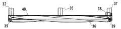
図1乃至図4は、本発明の全体の要旨を説明するための概要図である。本発明の実施例において、回転ブラシ36は、掃除機本体32の進行方向に対して直交方向に延設させた長さを有する回転軸のほぼ全長に亘って取り付けられた回転式のブラシとして形成されている。この回転ブラシ36は、進行方向側に塵埃を掃き出させるように、適宜な接地圧で且つ走行車輪31と逆回転するよう取り付けられている。これにより、単なる排気風だけでは取れにくかった絨毯の毛足などに入り込んだ塵埃を走行状態で吸気口35の付近に掃き出すことができる。
【0014】
一方、吸込口体40は、前記回転ブラシ36の全長を床面に向けて覆い且つ進行方向側を概ね閉塞させたダクトを形成している。実施例においては、この吸込口体40は、上面を閉塞し、且つ床面側を開口させた略断面コ字状の部材で形成され、この吸込口体40の上面の長さ方向の中央部には吸気口35が形成されると共に両端部には排気口37が形成されている。
【0015】
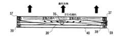
前記吸気口35から吸込まれた空気は、掃除機本体32内に設けられている図示しないフィルターを通して清浄化され、その清浄化された空気の一部は掃除機本体32に設けた図示しない排気口から外部へ排気されるが、清浄化された空気の残りは排気口37から吸込口体40の中央へ向かって排気される。これにより、吸込口体40は、回転ブラシ36の近傍で且つ回転ブラシ36の略全長に亘り空気流路を形成するため、吸込口体40の両端部に設けた排気口37からの清浄空気は、床面との間で塵埃を含んだ空気流となって中央部に形成した吸気口35に導入される。
【0016】
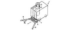
本発明の第1実施例は、図5及び図6に図示の如く、床面を走行可能な掃除機本体32の進行方向側に向けて塵埃を掃き出す回転ブラシ36を設け、該回転ブラシ36よりも進行方向側の近傍に吸込口35を有する吸込口体40を形成し、回転ブラシ36よりも進行方向側に排気口37を設けると共に、前記吸込口35から吸引された空気を掃除機本体32側で清浄化すると共に、その清浄化された空気の一部を排気口37から吸込口35に向かって排出することにより循環空気流を形成させたものである。
【0017】
また、本発明の実施例においては、前記回転ブラシ36よりも進行方向側の位置に、吸込口体40の上方から下方へ向かって回転ブラシ36に平行に壁を張り出させた空気流路規制部であるゴミストッパー41が設けられている。
【0018】
前記ゴミストッパー41が存在することにより、回転ブラシ36で進行方向側に向けて掃き出された塵埃は、吸込口体40の前側内壁に衝突して跳ね返り、再度、回転ブラシ36に戻ることが防止されるとともに、塵埃等を含んだ空気流が吸引口に到達する前に回転ブラシ36に流れ込み、塵埃等が回転ブラシ36側に逆流することが防止される。
【0019】
上記の構成によれば、掃除機本体32を進行方向に向けて走行させた場合、回転ブラシ36によって掃き出された絨毯などに含まれていた塵埃等は、吸込口体40の両端に取り付けられた排気口37から噴き出される排気風で吸込口体40の中央にある吸込口35付近まで集められ、吸込口35から掃除機本体32の内部循環路に吸引される。そして、吸引された塵埃は内部でフィルターなどを通過し、その一部が排気風として排気ホース33を通って排気口37から排出され、次いで、回転ブラシ36によって掃き出された塵埃を中央の吸気口35付近に運ぶ。
【0020】
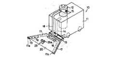
本発明の第2実施例は、図7及び図8に図示の如く、床面を走行可能な掃除機本体32の進行方向側に向けて塵埃を掃き出す回転ブラシ36を設け、該回転ブラシ36の真上近傍に吸込口35を有する吸込口体40を形成し、回転ブラシ36及び吸込口35よりも進行方向側に排気口37を設けると共に、前記吸込口35から吸引された空気を掃除機本体32側で清浄化すると共に、その清浄化された空気の一部を排気口37から吸込口35に向かって排出することにより循環空気流を形成させたものである。
【0021】
また、第1実施例と同様に、回転ブラシ36よりも進行方向側の位置に、吸込口体40の上方から下方へ向かって回転ブラシ36に平行に壁を張り出させた空気流路規制部であるゴミストッパー41を設けている。
【0022】
先の図5及び図6に示した第1実施例では、吸気口35を回転ブラシ36より前側に取り付けているが、本実施例では吸気口35を回転ブラシ35の真上近傍に設けている。回転ブラシによって掃き出された塵埃は、前方の床に直接落下するものと、吸込口体40の前側内壁に衝突した後前方の床に落下するものと、吸込口体40の前側内壁に衝突した後、ゴミストッパー41に衝突して前方の床に落下するものとが大半であるが、少量ではあるが吸込口体40の前側内壁に衝突する角度によってゴミストッパー41に衝突せずに回転ブラシ36に戻って回転ブラシ36の羽と羽の間に入るもの、及び、初めから回転ブラシの羽と羽の間に入ってしまうものが存在する。
【0023】
第1実施例の場合は、前方に落下した塵埃は排気口37から噴き出される排気風によって中央の吸込口へ向かうが、回転ブラシ36の羽と羽の間に入り込んだ塵埃はブラシの回転とともに後方へ移動し、後側に落ちて取り残される。これに対して本実施例の構成によれば、図7の上面図の如く、吸気口35を回転ブラシ36の略真上に取り付けていることから、回転ブラシ36の羽と羽の間に入り込んだ塵埃は空気流の作用により回転ブラシ36の真上位置まで移動した際に、吸気口35に吸込まれ、後方へ飛散することがないので、塵埃の後方への取り残しを大幅に減少させることができる。
【0024】
尚、本発明に係わる吸気口35の位置及び開口面積は、集塵効果等を考慮しつつ前記回転ブラシ36の真上乃至前記回転ブラシ36よりも進行方向側の何れかの位置にその一部または全体が開口されるよう調整され得る。
【0025】
【発明の効果】
本発明は、掃除機本体に内蔵された電動送風機により吸込まれる空気をフィルタに通して塵埃を捕捉し、前記フィルタを通過して前記電動送風機から排出された空気の全部もしくは一部を回収し循環させながら掃除をする電気掃除機に備えられる吸込口体において回転ブラシによって掃き出された塵埃を吸込口体の両端に吸込口に向かって取付られた排気口より排出される排気風によって中央の吸込口まで塵埃が集められ前記吸込口より吸込む事が出来る事によって、吸込み幅が広くなっても充分な集塵力が得られると共に、吸込口体を幅広くかつコンパクトに出来、かつ小さい吸引モーターでも十分な集塵能力を発揮させることができる。
【図面の簡単な説明】
【図1】本発明の全体の上面図である。
【図2】本発明の吸込口体の正面図である。
【図3】本発明の吸込口体の中での空気の流れを表した正面図である。
【図4】本発明の全体の側面図で空気の流れを表した図である。
【図5】本発明の吸気口35を回転ブラシ36より前側につけた時の吸込口体上面図である。
【図6】本発明の吸気口35を回転ブラシ36より前側につけた時の吸込口体側面図であり、ゴミの流れを表した図である。
【図7】本発明の吸気口35を回転ブラシ36の略真上につけた時の吸込口体上面図である。
【図8】本発明の吸気口35を回転ブラシ36の略真上につけた時の吸込口体側面図であり、ゴミの流れを表した図である。
【図9】従来の掃除機の斜視図である。
【図10】従来の掃除機の斜視図である。
【符号の説明】
1 台車
2 導管
3 掃除機本体
4 吸込口
5 排気吹き出し口
6 吹き寄せ管
6a 空気排出口
10 掃除機
11 自走式台車
12 掃除機本体
13 吸込口
14 導管
15 排気口
16 パイプジョイント
17 両吹き寄せ管
17a 吹き寄せ管先端
18 導管
19 空気排出口
20 蓋体
29 パイプ掛け
29a U字状の受部
30 走行部本体
31 走行車輪
32 掃除機本体
33 排気ホース
34 吸気ホース
35 吸気口
36 回転ブラシ
37 排気口
38 回転ブラシモーター
39 吸込口体車輪
40 吸込口体
41 ゴミストッパー[0001]
TECHNICAL FIELD OF THE INVENTION
BACKGROUND OF THE INVENTION 1. Field of the Invention The present invention relates to an air-circulating vacuum cleaner that travels on a floor and sucks dust, and more specifically, has an air outlet at both ends of a suction port body to discharge air toward the suction port. The present invention relates to a vacuum cleaner provided with blowing means.
[0002]
[Prior art]
2. Description of the Related Art Conventionally, as a vacuum cleaner in which blow-off means having an air discharge port for discharging air to an inner side surface are disposed on both front sides of a suction port, for example, a robot cleaner having a cleaner body mounted on a self-propelled dolly has been known. (See Japanese Utility Model Application Laid-Open No. 2-4539).
[0003]
The robot cleaner of Japanese Utility Model Laid-Open No. 2-4539 has a blower pipe provided with an air discharge hole on the inner side surface, so that at least a part is located outside the width of the suction port on both front sides of the suction port, The vacuum cleaner is characterized in that an exhaust outlet of the cleaner body is connected to the blower pipe so as to supply exhaust gas. However, in the robot cleaner of Japanese Utility Model Publication No. 2-4539, relatively large dust is deposited at the center. However, there was a problem that small objects were soared and scattered in the opposite direction, and there was a problem that corners could not be cleaned. The problem of Japanese Unexamined Utility Model Publication No. 2-4539 is solved by forming a lid that covers the dust collection area to be formed and by forming a rotating means for rotating the blowing means from a substantially horizontal state to a substantially vertical state. Was.
[0004]
[Problems to be solved by the present invention]
However, there is a problem that it is difficult to collect the dust that has entered the fur of the carpet by only the exhaust air of the above cleaning robot (Japanese Utility Model Laid-Open No. 2-4539, Japanese Utility Model Laid-Open No. 5-9448). In the mechanism of JP-A-2-4539, the suction port obstructs the robot from rotating near the wall.
[0005]
The cleaning robot disclosed in Japanese Utility Model Laid-Open No. 5-9448 has a rotatable mechanism. However, it is necessary to manually rotate the cleaning robot before cleaning, and a work area including both a wall and a large area can be automatically rotated. It cannot be cleaned cleanly.
[0006]
The present invention is intended to solve the conventional problems as described above, and provides a sufficient dust collecting force even if the suction width is wide, and can be configured compactly and has a small carpet with a small suction motor. It is an object of the present invention to provide a self-propelled vacuum cleaner capable of collecting dust that has penetrated into hairy feet.
[0007]
[Means for Solving the Problems]
In order to achieve the above object, the present invention provides, as a main configuration, a rotating brush that sweeps out dust on the floor toward the traveling direction of the cleaner main body that can travel on the floor, and attaches the rotating brush to the floor. Forming an air flow passage on the side of the rotating brush in the direction of travel of the rotating brush and forming a suction port body substantially blocking the direction of travel of the rotating brush, and forming a suction port near the upper portion of the rotating brush of the suction port body. And forming an exhaust port for discharging an air flow toward the suction port, and discharging all or a part of the air that has been cleaned from the suction port through the cleaner body side through the exhaust port. The exhausted air contains dust swept out by the rotating brush, and is sucked from the suction port and circulated.
[0008]
Further, in more detail, for the purpose of efficiently sucking dust collected by air swept out by the rotating brush and ejected from the exhaust port, the suction port is located above the rotary brush or above the rotary brush. The structure is such that it is opened in the traveling direction.
In more detail, the dust swept out by the rotating brush collides with the front inner wall of the suction opening body and rebounds, and returns to the rotating brush again, or before the air flow including dust reaches the suction opening. In order to prevent dust or the like from flowing into the rotating brush side and returning to the rotating brush and dust from being left behind, an air flow path regulating portion is formed between the air flow path and the rotating brush. did.
[0009]
More specifically, the present invention relates to a brush which is attached over substantially the entire length of a rotating shaft having a length in which the rotating brush extends in a direction perpendicular to the traveling direction, and a suction port body covering the rotating brush. By forming a suction port at the center portion of each of the above and forming exhaust ports at both end portions, it is possible to collect airflow near the suction port.
[0010]
The present invention, having the above-described configuration, has a cleaner main body that separates and captures dust sucked together with air from the suction port from the air, and then discharges the dust-separated air from the exhaust port. The rotating brush of the body sweeps out the dust that has entered the bristle feet of the carpet, sucks in the dust, and collects the dust at the central suction port by the exhaust air discharged from the exhaust ports attached to both ends of the mouth body. Can be inhaled through mouth.
[0011]
Further, the dust on the floor is scraped out by the brush of the suction port body, and the dust is collected to the central suction port by the exhaust air, so that even a small suction motor enables a sufficient dust collection capacity, and the suction port body is made wide and compact. be able to.
[0012]
BEST MODE FOR CARRYING OUT THE INVENTION
An embodiment according to the present invention will be described below with reference to the drawings.
[0013]
1 to 4 are schematic diagrams for explaining the overall gist of the present invention. In the embodiment of the present invention, the
[0014]
On the other hand, the
[0015]
The air sucked from the
[0016]
In the first embodiment of the present invention, as shown in FIGS. 5 and 6, a
[0017]
Further, in the embodiment of the present invention, the air flow path regulation is such that a wall extends in a direction parallel to the
[0018]
Due to the presence of the
[0019]
According to the above configuration, when the cleaner
[0020]
In the second embodiment of the present invention, as shown in FIGS. 7 and 8, a
[0021]
Further, similarly to the first embodiment, an air flow path restricting portion having a wall extending from the upper side of the
[0022]
In the first embodiment shown in FIGS. 5 and 6, the
[0023]
In the case of the first embodiment, the dust dropped forward goes to the central suction port by the exhaust air blown out from the
[0024]
In addition, the position and the opening area of the
[0025]
【The invention's effect】
The present invention captures dust by passing air sucked by an electric blower incorporated in a cleaner body through a filter, and collects all or a part of air discharged from the electric blower through the filter. The dust swept out by the rotating brush at the suction port provided in the vacuum cleaner that performs cleaning while circulating the dust at the center by the exhaust air discharged from the exhaust port attached to the suction port at both ends of the suction port body. By collecting dust up to the suction port and sucking it through the suction port, sufficient dust collection force can be obtained even if the suction width is wide, and the suction port body can be made wide and compact, and even with a small suction motor. A sufficient dust collecting ability can be exhibited.
[Brief description of the drawings]
FIG. 1 is an overall top view of the present invention.
FIG. 2 is a front view of the suction port body of the present invention.
FIG. 3 is a front view showing a flow of air in a suction port body of the present invention.
FIG. 4 is a diagram showing the flow of air in the overall side view of the present invention.
FIG. 5 is a top view of the suction port body when the
FIG. 6 is a side view of the suction port body when the
FIG. 7 is a top view of the suction port body when the
FIG. 8 is a side view of the suction port body when the
FIG. 9 is a perspective view of a conventional vacuum cleaner.
FIG. 10 is a perspective view of a conventional vacuum cleaner.
[Explanation of symbols]
DESCRIPTION OF SYMBOLS 1 Dolly 2 Conduit 3 Vacuum cleaner main body 4 Suction port 5 Exhaust air outlet 6 Blow-in pipe 6a Air exhaust port 10 Vacuum cleaner 11 Self-propelled trolley 12 Vacuum cleaner main body 13 Suction port 14 Duct 15 Exhaust port 16 Pipe joint 17 Double blow-in
Claims (4)
Translated fromJapanesePriority Applications (1)
| Application Number | Priority Date | Filing Date | Title |
|---|---|---|---|
| JP2002361459AJP2004160102A (en) | 2002-11-11 | 2002-11-11 | Vacuum cleaner |
Applications Claiming Priority (1)
| Application Number | Priority Date | Filing Date | Title |
|---|---|---|---|
| JP2002361459AJP2004160102A (en) | 2002-11-11 | 2002-11-11 | Vacuum cleaner |
Publications (2)
| Publication Number | Publication Date |
|---|---|
| JP2004160102Atrue JP2004160102A (en) | 2004-06-10 |
| JP2004160102A5 JP2004160102A5 (en) | 2005-10-20 |
Family
ID=32809732
Family Applications (1)
| Application Number | Title | Priority Date | Filing Date |
|---|---|---|---|
| JP2002361459APendingJP2004160102A (en) | 2002-11-11 | 2002-11-11 | Vacuum cleaner |
Country Status (1)
| Country | Link |
|---|---|
| JP (1) | JP2004160102A (en) |
Cited By (31)
| Publication number | Priority date | Publication date | Assignee | Title |
|---|---|---|---|---|
| WO2008099999A1 (en)* | 2007-02-15 | 2008-08-21 | Hanool Robotics Corp. | Cleaning robot having exhaust air feedback function |
| KR100869822B1 (en)* | 2007-02-15 | 2008-11-21 | 주식회사 한울로보틱스 | Exhaust reflux cleaning robot |
| EP1716801A3 (en)* | 2005-04-25 | 2009-04-29 | LG Electronics Inc. | Automatic cleaning device |
| US8239992B2 (en) | 2007-05-09 | 2012-08-14 | Irobot Corporation | Compact autonomous coverage robot |
| US8253368B2 (en) | 2004-01-28 | 2012-08-28 | Irobot Corporation | Debris sensor for cleaning apparatus |
| US8368339B2 (en) | 2001-01-24 | 2013-02-05 | Irobot Corporation | Robot confinement |
| US8374721B2 (en) | 2005-12-02 | 2013-02-12 | Irobot Corporation | Robot system |
| US8380350B2 (en) | 2005-12-02 | 2013-02-19 | Irobot Corporation | Autonomous coverage robot navigation system |
| US8386081B2 (en) | 2002-09-13 | 2013-02-26 | Irobot Corporation | Navigational control system for a robotic device |
| US8382906B2 (en) | 2005-02-18 | 2013-02-26 | Irobot Corporation | Autonomous surface cleaning robot for wet cleaning |
| US8390251B2 (en) | 2004-01-21 | 2013-03-05 | Irobot Corporation | Autonomous robot auto-docking and energy management systems and methods |
| US8387193B2 (en) | 2005-02-18 | 2013-03-05 | Irobot Corporation | Autonomous surface cleaning robot for wet and dry cleaning |
| US8396592B2 (en) | 2001-06-12 | 2013-03-12 | Irobot Corporation | Method and system for multi-mode coverage for an autonomous robot |
| US8412377B2 (en) | 2000-01-24 | 2013-04-02 | Irobot Corporation | Obstacle following sensor scheme for a mobile robot |
| US8417383B2 (en) | 2006-05-31 | 2013-04-09 | Irobot Corporation | Detecting robot stasis |
| US8418303B2 (en) | 2006-05-19 | 2013-04-16 | Irobot Corporation | Cleaning robot roller processing |
| US8428778B2 (en) | 2002-09-13 | 2013-04-23 | Irobot Corporation | Navigational control system for a robotic device |
| US8463438B2 (en) | 2001-06-12 | 2013-06-11 | Irobot Corporation | Method and system for multi-mode coverage for an autonomous robot |
| US8474090B2 (en) | 2002-01-03 | 2013-07-02 | Irobot Corporation | Autonomous floor-cleaning robot |
| US8515578B2 (en) | 2002-09-13 | 2013-08-20 | Irobot Corporation | Navigational control system for a robotic device |
| US8584305B2 (en) | 2005-12-02 | 2013-11-19 | Irobot Corporation | Modular robot |
| US8600553B2 (en) | 2005-12-02 | 2013-12-03 | Irobot Corporation | Coverage robot mobility |
| US8739355B2 (en) | 2005-02-18 | 2014-06-03 | Irobot Corporation | Autonomous surface cleaning robot for dry cleaning |
| US8780342B2 (en) | 2004-03-29 | 2014-07-15 | Irobot Corporation | Methods and apparatus for position estimation using reflected light sources |
| US8788092B2 (en) | 2000-01-24 | 2014-07-22 | Irobot Corporation | Obstacle following sensor scheme for a mobile robot |
| US8800107B2 (en) | 2010-02-16 | 2014-08-12 | Irobot Corporation | Vacuum brush |
| US8874264B1 (en) | 2004-07-07 | 2014-10-28 | Irobot Corporation | Celestial navigation system for an autonomous robot |
| US8930023B2 (en) | 2009-11-06 | 2015-01-06 | Irobot Corporation | Localization by learning of wave-signal distributions |
| US8972052B2 (en) | 2004-07-07 | 2015-03-03 | Irobot Corporation | Celestial navigation system for an autonomous vehicle |
| US9008835B2 (en) | 2004-06-24 | 2015-04-14 | Irobot Corporation | Remote control scheduler and method for autonomous robotic device |
| CN109452909A (en)* | 2018-12-26 | 2019-03-12 | 广东美的白色家电技术创新中心有限公司 | Ground brush assemblies and sweeping robot |
- 2002
- 2002-11-11JPJP2002361459Apatent/JP2004160102A/enactivePending
Cited By (99)
| Publication number | Priority date | Publication date | Assignee | Title |
|---|---|---|---|---|
| US8788092B2 (en) | 2000-01-24 | 2014-07-22 | Irobot Corporation | Obstacle following sensor scheme for a mobile robot |
| US8478442B2 (en) | 2000-01-24 | 2013-07-02 | Irobot Corporation | Obstacle following sensor scheme for a mobile robot |
| US8412377B2 (en) | 2000-01-24 | 2013-04-02 | Irobot Corporation | Obstacle following sensor scheme for a mobile robot |
| US9446521B2 (en) | 2000-01-24 | 2016-09-20 | Irobot Corporation | Obstacle following sensor scheme for a mobile robot |
| US8565920B2 (en) | 2000-01-24 | 2013-10-22 | Irobot Corporation | Obstacle following sensor scheme for a mobile robot |
| US8761935B2 (en) | 2000-01-24 | 2014-06-24 | Irobot Corporation | Obstacle following sensor scheme for a mobile robot |
| US9144361B2 (en) | 2000-04-04 | 2015-09-29 | Irobot Corporation | Debris sensor for cleaning apparatus |
| US8659255B2 (en) | 2001-01-24 | 2014-02-25 | Irobot Corporation | Robot confinement |
| US9038233B2 (en) | 2001-01-24 | 2015-05-26 | Irobot Corporation | Autonomous floor-cleaning robot |
| US8368339B2 (en) | 2001-01-24 | 2013-02-05 | Irobot Corporation | Robot confinement |
| US8686679B2 (en) | 2001-01-24 | 2014-04-01 | Irobot Corporation | Robot confinement |
| US8659256B2 (en) | 2001-01-24 | 2014-02-25 | Irobot Corporation | Robot confinement |
| US9582005B2 (en) | 2001-01-24 | 2017-02-28 | Irobot Corporation | Robot confinement |
| US9622635B2 (en) | 2001-01-24 | 2017-04-18 | Irobot Corporation | Autonomous floor-cleaning robot |
| US8838274B2 (en) | 2001-06-12 | 2014-09-16 | Irobot Corporation | Method and system for multi-mode coverage for an autonomous robot |
| US8463438B2 (en) | 2001-06-12 | 2013-06-11 | Irobot Corporation | Method and system for multi-mode coverage for an autonomous robot |
| US9104204B2 (en) | 2001-06-12 | 2015-08-11 | Irobot Corporation | Method and system for multi-mode coverage for an autonomous robot |
| US8396592B2 (en) | 2001-06-12 | 2013-03-12 | Irobot Corporation | Method and system for multi-mode coverage for an autonomous robot |
| US8763199B2 (en) | 2002-01-03 | 2014-07-01 | Irobot Corporation | Autonomous floor-cleaning robot |
| US8656550B2 (en) | 2002-01-03 | 2014-02-25 | Irobot Corporation | Autonomous floor-cleaning robot |
| US8671507B2 (en) | 2002-01-03 | 2014-03-18 | Irobot Corporation | Autonomous floor-cleaning robot |
| US8516651B2 (en) | 2002-01-03 | 2013-08-27 | Irobot Corporation | Autonomous floor-cleaning robot |
| US8474090B2 (en) | 2002-01-03 | 2013-07-02 | Irobot Corporation | Autonomous floor-cleaning robot |
| US9128486B2 (en) | 2002-01-24 | 2015-09-08 | Irobot Corporation | Navigational control system for a robotic device |
| US8428778B2 (en) | 2002-09-13 | 2013-04-23 | Irobot Corporation | Navigational control system for a robotic device |
| US8793020B2 (en) | 2002-09-13 | 2014-07-29 | Irobot Corporation | Navigational control system for a robotic device |
| US8515578B2 (en) | 2002-09-13 | 2013-08-20 | Irobot Corporation | Navigational control system for a robotic device |
| US8781626B2 (en) | 2002-09-13 | 2014-07-15 | Irobot Corporation | Navigational control system for a robotic device |
| US8386081B2 (en) | 2002-09-13 | 2013-02-26 | Irobot Corporation | Navigational control system for a robotic device |
| US9949608B2 (en) | 2002-09-13 | 2018-04-24 | Irobot Corporation | Navigational control system for a robotic device |
| US8749196B2 (en) | 2004-01-21 | 2014-06-10 | Irobot Corporation | Autonomous robot auto-docking and energy management systems and methods |
| US8461803B2 (en) | 2004-01-21 | 2013-06-11 | Irobot Corporation | Autonomous robot auto-docking and energy management systems and methods |
| US9215957B2 (en) | 2004-01-21 | 2015-12-22 | Irobot Corporation | Autonomous robot auto-docking and energy management systems and methods |
| US8854001B2 (en) | 2004-01-21 | 2014-10-07 | Irobot Corporation | Autonomous robot auto-docking and energy management systems and methods |
| US8390251B2 (en) | 2004-01-21 | 2013-03-05 | Irobot Corporation | Autonomous robot auto-docking and energy management systems and methods |
| US8598829B2 (en) | 2004-01-28 | 2013-12-03 | Irobot Corporation | Debris sensor for cleaning apparatus |
| US8378613B2 (en) | 2004-01-28 | 2013-02-19 | Irobot Corporation | Debris sensor for cleaning apparatus |
| US8253368B2 (en) | 2004-01-28 | 2012-08-28 | Irobot Corporation | Debris sensor for cleaning apparatus |
| US8456125B2 (en) | 2004-01-28 | 2013-06-04 | Irobot Corporation | Debris sensor for cleaning apparatus |
| US9360300B2 (en) | 2004-03-29 | 2016-06-07 | Irobot Corporation | Methods and apparatus for position estimation using reflected light sources |
| US8780342B2 (en) | 2004-03-29 | 2014-07-15 | Irobot Corporation | Methods and apparatus for position estimation using reflected light sources |
| US9008835B2 (en) | 2004-06-24 | 2015-04-14 | Irobot Corporation | Remote control scheduler and method for autonomous robotic device |
| US9486924B2 (en) | 2004-06-24 | 2016-11-08 | Irobot Corporation | Remote control scheduler and method for autonomous robotic device |
| US8874264B1 (en) | 2004-07-07 | 2014-10-28 | Irobot Corporation | Celestial navigation system for an autonomous robot |
| US8972052B2 (en) | 2004-07-07 | 2015-03-03 | Irobot Corporation | Celestial navigation system for an autonomous vehicle |
| US9223749B2 (en) | 2004-07-07 | 2015-12-29 | Irobot Corporation | Celestial navigation system for an autonomous vehicle |
| US9229454B1 (en) | 2004-07-07 | 2016-01-05 | Irobot Corporation | Autonomous mobile robot system |
| US8392021B2 (en) | 2005-02-18 | 2013-03-05 | Irobot Corporation | Autonomous surface cleaning robot for wet cleaning |
| US8855813B2 (en) | 2005-02-18 | 2014-10-07 | Irobot Corporation | Autonomous surface cleaning robot for wet and dry cleaning |
| US8774966B2 (en) | 2005-02-18 | 2014-07-08 | Irobot Corporation | Autonomous surface cleaning robot for wet and dry cleaning |
| US10470629B2 (en) | 2005-02-18 | 2019-11-12 | Irobot Corporation | Autonomous surface cleaning robot for dry cleaning |
| US8739355B2 (en) | 2005-02-18 | 2014-06-03 | Irobot Corporation | Autonomous surface cleaning robot for dry cleaning |
| US8782848B2 (en) | 2005-02-18 | 2014-07-22 | Irobot Corporation | Autonomous surface cleaning robot for dry cleaning |
| US8382906B2 (en) | 2005-02-18 | 2013-02-26 | Irobot Corporation | Autonomous surface cleaning robot for wet cleaning |
| US9445702B2 (en) | 2005-02-18 | 2016-09-20 | Irobot Corporation | Autonomous surface cleaning robot for wet and dry cleaning |
| US8670866B2 (en) | 2005-02-18 | 2014-03-11 | Irobot Corporation | Autonomous surface cleaning robot for wet and dry cleaning |
| US8387193B2 (en) | 2005-02-18 | 2013-03-05 | Irobot Corporation | Autonomous surface cleaning robot for wet and dry cleaning |
| US8985127B2 (en) | 2005-02-18 | 2015-03-24 | Irobot Corporation | Autonomous surface cleaning robot for wet cleaning |
| EP1716801A3 (en)* | 2005-04-25 | 2009-04-29 | LG Electronics Inc. | Automatic cleaning device |
| US9149170B2 (en) | 2005-12-02 | 2015-10-06 | Irobot Corporation | Navigating autonomous coverage robots |
| US8661605B2 (en) | 2005-12-02 | 2014-03-04 | Irobot Corporation | Coverage robot mobility |
| US10524629B2 (en) | 2005-12-02 | 2020-01-07 | Irobot Corporation | Modular Robot |
| US8954192B2 (en) | 2005-12-02 | 2015-02-10 | Irobot Corporation | Navigating autonomous coverage robots |
| US8950038B2 (en) | 2005-12-02 | 2015-02-10 | Irobot Corporation | Modular robot |
| US8600553B2 (en) | 2005-12-02 | 2013-12-03 | Irobot Corporation | Coverage robot mobility |
| US8978196B2 (en) | 2005-12-02 | 2015-03-17 | Irobot Corporation | Coverage robot mobility |
| US8606401B2 (en) | 2005-12-02 | 2013-12-10 | Irobot Corporation | Autonomous coverage robot navigation system |
| US8584307B2 (en) | 2005-12-02 | 2013-11-19 | Irobot Corporation | Modular robot |
| US8374721B2 (en) | 2005-12-02 | 2013-02-12 | Irobot Corporation | Robot system |
| US8584305B2 (en) | 2005-12-02 | 2013-11-19 | Irobot Corporation | Modular robot |
| US8380350B2 (en) | 2005-12-02 | 2013-02-19 | Irobot Corporation | Autonomous coverage robot navigation system |
| US8761931B2 (en) | 2005-12-02 | 2014-06-24 | Irobot Corporation | Robot system |
| US9144360B2 (en) | 2005-12-02 | 2015-09-29 | Irobot Corporation | Autonomous coverage robot navigation system |
| US9599990B2 (en) | 2005-12-02 | 2017-03-21 | Irobot Corporation | Robot system |
| US9392920B2 (en) | 2005-12-02 | 2016-07-19 | Irobot Corporation | Robot system |
| US8572799B2 (en) | 2006-05-19 | 2013-11-05 | Irobot Corporation | Removing debris from cleaning robots |
| US8528157B2 (en) | 2006-05-19 | 2013-09-10 | Irobot Corporation | Coverage robots and associated cleaning bins |
| US9955841B2 (en) | 2006-05-19 | 2018-05-01 | Irobot Corporation | Removing debris from cleaning robots |
| US10244915B2 (en) | 2006-05-19 | 2019-04-02 | Irobot Corporation | Coverage robots and associated cleaning bins |
| US8418303B2 (en) | 2006-05-19 | 2013-04-16 | Irobot Corporation | Cleaning robot roller processing |
| US9492048B2 (en) | 2006-05-19 | 2016-11-15 | Irobot Corporation | Removing debris from cleaning robots |
| US8417383B2 (en) | 2006-05-31 | 2013-04-09 | Irobot Corporation | Detecting robot stasis |
| US9317038B2 (en) | 2006-05-31 | 2016-04-19 | Irobot Corporation | Detecting robot stasis |
| US8468645B2 (en) | 2007-02-15 | 2013-06-25 | Hanool Robotics Corp. | Cleaning robot having exhaust air feedback function |
| KR100869822B1 (en)* | 2007-02-15 | 2008-11-21 | 주식회사 한울로보틱스 | Exhaust reflux cleaning robot |
| EP2111145A4 (en)* | 2007-02-15 | 2010-03-17 | Hanool Robotics Corp | Cleaning robot having exhaust air feedback function |
| WO2008099999A1 (en)* | 2007-02-15 | 2008-08-21 | Hanool Robotics Corp. | Cleaning robot having exhaust air feedback function |
| US10070764B2 (en) | 2007-05-09 | 2018-09-11 | Irobot Corporation | Compact autonomous coverage robot |
| US8438695B2 (en) | 2007-05-09 | 2013-05-14 | Irobot Corporation | Autonomous coverage robot sensing |
| US8839477B2 (en) | 2007-05-09 | 2014-09-23 | Irobot Corporation | Compact autonomous coverage robot |
| US9480381B2 (en) | 2007-05-09 | 2016-11-01 | Irobot Corporation | Compact autonomous coverage robot |
| US8239992B2 (en) | 2007-05-09 | 2012-08-14 | Irobot Corporation | Compact autonomous coverage robot |
| US11072250B2 (en) | 2007-05-09 | 2021-07-27 | Irobot Corporation | Autonomous coverage robot sensing |
| US11498438B2 (en) | 2007-05-09 | 2022-11-15 | Irobot Corporation | Autonomous coverage robot |
| US8930023B2 (en) | 2009-11-06 | 2015-01-06 | Irobot Corporation | Localization by learning of wave-signal distributions |
| US8800107B2 (en) | 2010-02-16 | 2014-08-12 | Irobot Corporation | Vacuum brush |
| US10314449B2 (en) | 2010-02-16 | 2019-06-11 | Irobot Corporation | Vacuum brush |
| US11058271B2 (en) | 2010-02-16 | 2021-07-13 | Irobot Corporation | Vacuum brush |
| CN109452909A (en)* | 2018-12-26 | 2019-03-12 | 广东美的白色家电技术创新中心有限公司 | Ground brush assemblies and sweeping robot |
Similar Documents
| Publication | Publication Date | Title |
|---|---|---|
| JP2004160102A (en) | Vacuum cleaner | |
| CN101273860B (en) | Robot cleaner with improved dust collector | |
| US7124467B2 (en) | Edge cleaning system for vacuum cleaner | |
| US6725500B2 (en) | Air recirculating surface cleaning device | |
| CN109124465A (en) | Hand held cleaner and combinations thereof part, push-down dust catcher | |
| JP2004160102A5 (en) | ||
| CN108888177A (en) | Roller brush assembly and cleaning device with it | |
| CN111432704A (en) | Robot cleaner | |
| CN209404635U (en) | Roller brush assembly and cleaning device with it | |
| JP2002165731A (en) | Electric vacuum cleaner | |
| CN209695075U (en) | Dust-absorbing floor brush and dust catcher with it | |
| JP2000166826A (en) | Electric vacuum cleaner | |
| CN115299819A (en) | Automatic cleaning equipment | |
| JP3542264B2 (en) | Suction port for vacuum cleaner and vacuum cleaner having the same | |
| JP3162011B2 (en) | Vacuum cleaner and its suction body | |
| JP2001149281A (en) | Suction port body and vacuum cleaner | |
| JP3656816B2 (en) | Suction port and vacuum cleaner | |
| JP2002085303A (en) | Electric vacuum cleaner | |
| JPH07275164A (en) | Upright vacuum cleaner | |
| JP3162031B2 (en) | Suction port body and vacuum cleaner | |
| JP3877481B2 (en) | Suction port and circulating vacuum cleaner | |
| KR20070021763A (en) | Zero exhaust robot cleaner | |
| KR0137488B1 (en) | Dust scattering device of vacuum cleaner | |
| KR100672398B1 (en) | Exhaust reflux vacuum cleaner | |
| KR100628183B1 (en) | Vacuum cleaner |
Legal Events
| Date | Code | Title | Description |
|---|---|---|---|
| A521 | Written amendment | Free format text:JAPANESE INTERMEDIATE CODE: A523 Effective date:20050630 | |
| RD02 | Notification of acceptance of power of attorney | Free format text:JAPANESE INTERMEDIATE CODE: A7422 Effective date:20050630 | |
| A621 | Written request for application examination | Free format text:JAPANESE INTERMEDIATE CODE: A621 Effective date:20050912 | |
| A977 | Report on retrieval | Effective date:20080111 Free format text:JAPANESE INTERMEDIATE CODE: A971007 | |
| A131 | Notification of reasons for refusal | Effective date:20080122 Free format text:JAPANESE INTERMEDIATE CODE: A131 | |
| A02 | Decision of refusal | Free format text:JAPANESE INTERMEDIATE CODE: A02 Effective date:20080617 |