JP2004159296A - Packet communication system, node, relay node, relay node capable of deleting used address, and packet communication method - Google Patents
Packet communication system, node, relay node, relay node capable of deleting used address, and packet communication methodDownload PDFInfo
- Publication number
- JP2004159296A JP2004159296AJP2003207641AJP2003207641AJP2004159296AJP 2004159296 AJP2004159296 AJP 2004159296AJP 2003207641 AJP2003207641 AJP 2003207641AJP 2003207641 AJP2003207641 AJP 2003207641AJP 2004159296 AJP2004159296 AJP 2004159296A
- Authority
- JP
- Japan
- Prior art keywords
- packet
- address
- storage area
- stored
- relay node
- Prior art date
- Legal status (The legal status is an assumption and is not a legal conclusion. Google has not performed a legal analysis and makes no representation as to the accuracy of the status listed.)
- Granted
Links
Images


Landscapes
- Data Exchanges In Wide-Area Networks (AREA)
Abstract
Translated fromJapaneseDescription
Translated fromJapanese【0001】
【発明の属する技術分野】
本発明は、パケット通信システムに関するものである。
【0002】
【従来の技術】
パケット通信のプロトコルとして、近年、IPv6が普及してきている。このIPv6では、送信元のノード(例えば、パーソナルコンピュータ等の送信端末)から、送信先のノード(例えば、パーソナルコンピュータ等の送信端末)へパケットを送信する際に、そのパケットが経由する中継ノード(例えば、ルータ)のアドレスを送信元のノードが指定するルーティングヘッダ(Routing Header。以下、本明細書では「RHO」と呼ぶ。)を拡張ヘッダとして付加可能とされている(例えば、非特許文献1参照)。IPv6では、このRHOを設けることによって、パケットが経由する中継ノードの経路を設定することができる。
【0003】
【非特許文献1】
Internet Society、”Internet Protocol, Version 6 (IPv6) Specification”、4.4 Routing Header Page.12、[online]、1998年12月3日、<URL:http://www.ietf.org/rfc/rfc2460.txt>
【0004】
【発明が解決しようとする課題】
しかしながら、上述したIPv6では、送信元のノードがRHOをパケットに付加すると、送信先のノードまでパケットのサイズが不変のまま中継され、サイズの大きいパケットがネットワークに大きな負荷を与えるという問題点がある。
【0005】
本発明は上記問題点を解決するためになされたもので、RHOを付加すること可能としつつ、ネットワークに与える負荷を抑制可能な、パケット通信システム、ノード、中継ノード、使用済みアドレスを削除可能な中継ノード、及びパケット通信方法を提供することを課題としている。
【0006】
【課題を解決するための手段】
上記課題を解決するため、本発明のパケット通信システムは、宛先のノードのアドレスを格納する宛先アドレス格納領域を含む第1のヘッダを備え、経路となる1以上の中継ノードのアドレスを格納する経由アドレス格納領域を有する第2のヘッダを付加可能なパケットを、送信元のノードから1以上の中継ノードを経由して送信先のノードへ送信するパケット通信システムであって、上記送信元のノードは、上記送信先のノードへ上記パケットを送信するために当該パケットが経由する中継ノードの経路を示す経路情報が格納される経路情報格納手段と、上記経路情報格納手段に格納された上記経路情報に基づいて、上記パケットの上記宛先アドレス格納領域に当該パケットが第1に経由する第1の上記中継ノードのアドレスを格納すると共に、当該パケットに上記第2のヘッダを設け、当該経路情報に基づいて、当該パケットが上記第1の中継ノード以降に経由する上記中継ノードのアドレスをその経由順に上記経由アドレス格納領域に格納し、当該経由アドレス格納領域における後尾に上記送信先のノードのアドレスを格納する経路設定手段と、上記パケットを送信するパケット送信手段とを備え、上記中継ノードは、上記パケットを受信するパケット受信手段と、上記パケット受信手段によって受信される上記パケットの上記宛先アドレス格納領域に格納されたアドレスが、当該中継ノードのアドレスと一致する場合に、当該パケットにおける上記経由アドレス格納領域の先頭に格納されたアドレスを、上記宛先アドレス格納領域に格納し、上記経由アドレス格納領域の上記アドレスが格納された先頭の領域より後方に格納された当該パケットのデータを、上記アドレスの一つの容量に相当する分、当該パケットの前方にシフトするパケット処理を実行するパケット処理手段と、上記パケット処理手段によって処理された上記パケットを送信する第2のパケット送信手段とを備えることを特徴としている。
【0007】
また、上記課題を解決するため、本発明の中継ノードは、宛先のノードのアドレスを格納する宛先アドレス格納領域を含む第1のヘッダを備え、経路となる1以上の中継ノードのアドレスを格納する経由アドレス格納領域を有する第2のヘッダを付加可能なパケットを、送信元のノードから1以上の中継ノードを経由して送信先のノードへ送信するパケット通信システムにおける、上記中継ノードであって、上記パケットを受信する受信手段と、上記パケット受信手段によって受信される上記パケットの上記宛先アドレス格納領域に格納されたアドレスが、当該中継ノードのアドレスと一致する場合に、当該パケットにおける上記経由アドレス格納領域の先頭に格納されたアドレスを、上記宛先アドレス格納領域に格納し、上記経由アドレス格納領域の上記アドレスが格納された先頭の領域より後方に格納された当該パケットのデータを、上記アドレスの一つの容量に相当する分、当該パケットの前方にシフトするパケット処理を実行するパケット処理手段と、上記パケット処理手段によって処理された上記パケットを送信する第2のパケット送信手段とを備えることを特徴としている。
【0008】
また、上記課題を解決するため、本発明のパケット通信方法は、宛先のノードのアドレスを格納する宛先アドレス格納領域を含む第1のヘッダを備え、経路となる1以上の中継ノードのアドレスを格納する経由アドレス格納領域を有する第2のヘッダを付加可能なパケットを、送信元のノードから1以上の中継ノードを経由して送信先のノードへ送信するパケット通信方法であって、上記送信元のノードが備える経路設定手段が、経路情報格納手段に格納された上記パケットを上記送信先のノードへ送信するために当該パケットが経由する中継ノードの経路を示す経路情報に基づいて、上記パケットの上記宛先アドレス格納領域に当該パケットが第1に経由する第1の上記中継ノードのアドレスを格納すると共に、当該パケットに上記第2のヘッダを設け、当該経路情報に基づいて、当該パケットが上記第1の中継ノード以降に経由する上記中継ノードのアドレスをその経由順に上記経由アドレス格納領域に格納し、当該経由アドレス格納領域における後尾に上記送信先のノードのアドレスを格納する経路設定ステップと、上記送信元のノードが備えるパケット送信手段が、上記パケットを送信するパケット送信ステップと、上記中継ノードが備えるパケット受信手段が上記パケットを受信するパケット受信ステップと、上記中継ノードが備えるパケット処理手段が、上記パケット受信手段によって受信される上記パケットの上記宛先アドレス格納領域に格納されたアドレスが、当該中継ノードのアドレスと一致する場合に、当該パケットにおける上記経由アドレス格納領域の先頭に格納されたアドレスを、上記宛先アドレス格納領域に格納し、上記経由アドレス格納領域の上記アドレスが格納された先頭の領域より後方に格納された当該パケットのデータを、上記アドレスの一つの容量に相当する分、当該パケットの前方にシフトするパケット処理を実行するパケット処理ステップと、上記中継ノードが備える第2のパケット送信手段が、上記パケット処理手段によって処理された上記パケットを送信する第2のパケット送信ステップとを備えることを特徴としている。
【0009】
これらの発明によれば、送信元のノードによって送信されるパケットには、第1のヘッダの宛先アドレス格納領域に、このパケットが第1に経由する中継ノードのアドレスが格納されている。更にこのパケットには第2のヘッダが付加されている。この第2のヘッダには、パケットが更に通過すべき中継ノードのアドレスと、送信先のノードのアドレスが、その経由順に格納されている。このようなパケットを受信する中継ノードには、以下のようなパケット処理を実行するパケット処理手段が設けられている。このパケット処理では、中継ノードのアドレスと、パケットの宛先アドレス格納領域に格納されたアドレスが一致する場合に、宛先アドレス格納領域に経由アドレス格納領域の先頭に格納されたアドレスを格納する。また、経由アドレス格納領域における先頭のアドレスが格納された領域以降のパケットのデータを、1つのアドレスのサイズに相当する分だけ、前方へシフトする。これによって、中継ノードを経由する度に、既に不要となったアドレス分のサイズが削減されたパケットを送信できるので、第2のヘッダによってパケットが中継される経路を設定しつつ、パケットのサイズを小さくして、ネットワークに与える負荷を抑制することが可能となる。
【0010】
また、本発明のパケット通信システムにおいては、上記送信元のノードが備える上記経路設定手段は、上記パケットの上記第2のヘッダに所定のタイプ情報を格納し、上記中継ノードが備える上記パケット処理手段は、上記パケット受信手段によって受信される上記パケットの上記第2のヘッダに上記所定のタイプ情報が設定されている場合に、上記パケット処理を実行することを特徴としても良い。
【0011】
また、本発明の送信ノードにおいては、宛先のノードのアドレスを格納する宛先アドレス格納領域を含む第1のヘッダを備え、経路となる1以上の中継ノードのアドレスを格納する経由アドレス格納領域を有する第2のヘッダを付加可能なパケットを、送信元のノードから1以上の中継ノードを経由して送信先のノードへ送信するパケット通信システムにおける、上記送信元のノードであって、上記送信先のノードへ上記パケットを送信するために当該パケットが経由する中継ノードの経路を示す経路情報が格納される経路情報格納手段と、上記経路情報格納手段に格納された上記経路情報に基づいて、上記パケットの上記宛先アドレス格納領域に当該パケットが第1に経由する第1の上記中継ノードのアドレスを格納すると共に、当該パケットに上記第2のヘッダを設け、当該第2のヘッダに所定のタイプ情報を格納し、上記経路情報に基づいて、当該パケットが上記第1の中継ノード以降に経由する上記中継ノードのアドレスをその経由順に上記経由アドレス格納領域に格納し、当該経由アドレス格納領域における後尾に上記送信先のノードのアドレスを格納する経路設定手段と、上記パケットを送信するパケット送信手段とを備えることを特徴としても良い。
【0012】
また、本発明の中継ノードにおいては、上記パケット処理手段は、上記パケット受信手段によって受信される上記パケットの上記第2のヘッダに所定のタイプ情報が設定されている場合に、上記パケット処理を実行することを特徴としても良い。
【0013】
また、本発明のパケット通信方法においては、上記経路設定ステップにおいて、上記送信元のノードが備える上記経路設定手段は、上記パケットの上記第2のヘッダに所定のタイプ情報を格納し、上記パケット処理ステップにおいて、上記中継ノードが備える上記パケット処理手段は、上記パケット受信手段によって受信される上記パケットの上記第2のヘッダに上記所定のタイプ情報が設定されている場合に、上記パケット処理を実行することを特徴としても良い。
【0014】
これらの発明によれば、送信元のノードによって、パケットに付加した第2のヘッダに所定のタイプ情報を設定する。中継ノードにおいては、この所定のタイプ情報が設定されている場合にのみ、上記したパケット処理を実行できるので、本発明による上述したパケット処理を柔軟に適用することができる。
【0015】
また、本発明のパケット通信システムにおいては、上記中継ノードが備える上記パケット処理手段は、上記パケット処理において、上記パケット受信手段によって受信される上記パケットの上記宛先アドレス格納領域に格納されたアドレスと当該中継ノードのアドレスが一致し、かつ、上記経由アドレス格納領域に格納されたアドレスが1つであると判断する場合に、上記経由アドレス格納領域に格納されたアドレスを、上記宛先アドレス格納領域に格納すると共に、当該パケットの上記第2のヘッダの領域より後方のデータを、上記第2のヘッダの容量に相当する分、前方へシフトすることが好ましい。
【0016】
また、本発明の中継ノードにおいては、上記パケット処理手段は、上記パケット処理において、上記パケット受信手段によって受信される上記パケットの上記宛先アドレス格納領域に格納されたアドレスと当該中継ノードのアドレスが一致し、かつ、上記経由アドレス格納領域に格納されたアドレスが1つであると判断する場合に、上記経由アドレス格納領域に格納されたアドレスを、上記宛先アドレス格納領域に格納すると共に、当該パケットの上記第2のヘッダの領域より後方のデータを、上記第2のヘッダの容量に相当する分、前方へシフトすることが好ましい。
【0017】
また、本発明のパケット通信方法においては、上記パケット処理ステップにおいて、上記中継ノードが備える上記パケット処理手段は、上記パケット受信手段によって受信される上記パケットの上記宛先アドレス格納領域に格納されたアドレスと当該中継ノードのアドレスが一致し、かつ、上記経由アドレス格納領域に格納されたアドレスが1つであると判断する場合に、上記経由アドレス格納領域に格納されたアドレスを、上記宛先アドレス格納領域に格納すると共に、当該パケットの上記第2のヘッダの領域より後方のデータを、上記第2のヘッダの容量に相当する分、前方へシフトすることが好ましい。
【0018】
この発明によれば、上述したパケットを最後に中継する中継ノードにおいて、パケットの第2のヘッダの領域より後方のデータを、上記第2のヘッダの容量に相当する分シフトするので、第2のヘッダ自体の容量を削減できる。その結果、更にパケットのサイズを小さくできるので、ネットワークに与える負荷を抑制することができる。
【0019】
また、本発明のパケット通信システムにおいては、上記中継ノードは、上記送信先のノードへ上記パケットを送信するために当該パケットが経由する中継ノードの経路を示す経路情報が格納される第2の経路情報格納手段を更に備えることを特徴としても良い。
【0020】
また、本発明の中継ノードにおいては、上記送信先のノードへ上記パケットを送信するために当該パケットが経由する中継ノードの経路を示す経路情報が格納される第2の経路情報格納手段を更に備えることを特徴としても良い。
【0021】
このように、中継ノードにおいても、経路情報が格納された第2の経路情報格納手段を備えることによって、以下に示すように、中継ノードにおいても、パケットの経路を設定することが可能となる。
【0022】
また、本発明のパケット通信システムにおいては、上記中継ノードが備える上記パケット処理手段は、上記パケット処理において、上記経由アドレス格納領域の先頭に格納されたアドレスをもつ中継ノードが、当該パケットを中継できないと判断する場合に、上記第2の経路情報格納手段に格納された上記経路情報に基いて、当該パケットが次に経由すべき中継ノードのアドレス決定し、当該決定された上記アドレスを当該パケットの上記宛先アドレス格納領域に格納すると共に、上記経由アドレス格納領域の上記アドレスが格納された先頭の領域より後方に格納された当該パケットのデータを、上記アドレスの一つの容量に相当する分、当該パケットの前方にシフトすることを特徴とすることが好ましい。
【0023】
また、本発明の中継ノードにおいては、上記パケット処理手段は、上記パケット処理において、上記経由アドレス格納領域の先頭に格納されたアドレスをもつ中継ノードが、当該パケットを中継できないと判断する場合に、上記第2の経路情報格納手段に格納された上記経路情報に基いて、当該パケットが次に経由すべき中継ノードのアドレス決定し、当該決定された上記アドレスを当該パケットの上記宛先アドレス格納領域に格納すると共に、上記経由アドレス格納領域の上記アドレスが格納された先頭の領域より後方に格納された当該パケットのデータを、上記アドレスの一つの容量に相当する分、当該パケットの前方にシフトすることを特徴とすることが好ましい。
【0024】
また、本発明のパケット通信方法においては、上記パケット処理ステップにおいて、上記中継ノードが備える上記パケット処理手段は、上記経由アドレス格納領域の先頭に格納されたアドレスをもつ中継ノードが、当該パケットを中継できないと判断する場合に、上記中継ノードが備える第2の経路情報格納手段に格納された上記送信先のノードへ当該パケットを送信するための中継ノードの経路を示す経路情報に基いて、当該パケットが次に経由すべき中継ノードのアドレス決定し、当該決定された上記アドレスを当該パケットの上記宛先アドレス格納領域に格納すると共に、上記経由アドレス格納領域の上記アドレスが格納された先頭の領域より後方に格納された当該パケットのデータを、上記アドレスの一つの容量に相当する分、当該パケットの前方にシフトすることを特徴とすることが好ましい。
【0025】
これらの発明によれば、中継ノードが、パケットの第2のヘッダに含まれる経由アドレス格納領域の先頭に格納されたアドレスをもつ中継ノード、すなわち、次にパケットを中継すべきノードに異常があって、パケットを中継できないと判断する場合に、第2の経路情報格納手段に格納された経路情報に基づいて、次にこのパケットを中継可能な中継ノードを決定し、この中継ノードのアドレスをパケットの宛先アドレス格納領域に格納する。したがって、パケットを中継ノードで途切れることなく送信先のノードへ送信できる。また、経路の途中の中継ノードがパケットを中継できない場合に、送信元のノードからパケット再送するのではなく、直前の中継ノードが経路を再設定して、パケットを中継するので、パケットの中継に要するタイムラグを少なくできる。更に、このパケットにおいて、経由アドレス格納領域の上記のアドレスが格納された先頭の領域をこれより後方のデータを前方にシフトすることによって削除するので、このパケットのサイズを小さくすることができる。その結果、第2のヘッダによってパケットが中継される経路を設定しつつ、パケットのサイズを小さくして、ネットワークに与える負荷を抑制することが可能となる。
【0026】
また、本発明のパケット通信システムにおいては、上記中継ノードは、上記パケット受信手段によって受信される上記パケットに上記第2のヘッダが付加されていないと判断する場合に、当該パケットの上記宛先アドレス格納領域に格納されたアドレスを一時的に記憶すると共に、当該パケットに上記第2のヘッダを設け、上記経路情報格納手段に格納された上記経路情報に基いて、当該パケットが当該中継ノードの次に経由すべき第1の中継ノードのアドレスを上記宛先アドレス格納領域に格納し、当該経路情報に基いて、当該パケットが上記第1の中継ノード以降に経由すべき中継ノードのアドレスをその経由順に上記経由アドレス格納領域に格納し、当該経由アドレス格納領域における後尾に上記一時的に記憶したアドレスを格納する第2の経路設定手段を更に備えることを特徴としても良い。
【0027】
また、本発明の中継ノードにおいては、上記パケット受信手段によって受信される上記パケットに上記第2のヘッダが付加されていないと判断する場合に、当該パケットの上記宛先アドレス格納領域に格納されたアドレスを一時的に記憶すると共に、当該パケットに上記第2のヘッダを設け、上記経路情報格納手段に格納された上記経路情報に基いて、当該パケットが当該中継ノードの次に経由すべき第1の中継ノードのアドレスを上記宛先アドレス格納領域に格納し、当該経路情報に基いて、当該パケットが上記第1の中継ノード以降に経由すべき中継ノードのアドレスをその経由順に上記経由アドレス格納領域に格納し、当該経由アドレス格納領域における後尾に上記一時的に記憶したアドレスを格納する第2の経路設定手段を更に備えることを特徴としても良い。
【0028】
また、本発明のパケット通信方法においては、上記中継ノードの備える第2の経路設定手段が、上記パケット受信手段によって受信される上記パケットに上記第2のヘッダが付加されていないと判断する場合に、当該パケットの上記宛先アドレス格納領域に格納されたアドレスを一時的に記憶すると共に、当該パケットに上記第2のヘッダを設け、上記中継ノードが備える第2の経路情報格納手段に格納された上記送信先のノードへ当該パケットを送信するための中継ノードの経路を示す経路情報に基いて、当該パケットが当該中継ノードの次に経由すべき第1の中継ノードのアドレスを上記宛先アドレス格納領域に格納し、当該経路情報に基いて、当該パケットが上記第1の中継ノード以降に経由すべき中継ノードのアドレスをその経由順に上記経由アドレス格納領域に格納し、当該経由アドレス格納領域における後尾に上記一時的に記憶したアドレスを格納する第2の経路設定ステップを更に備えることを特徴としても良い。
【0029】
これらの発明によれば、送信元のノードが経路情報を特定できない場合や、経路情報を特定せずにパケットを送信する場合、すなわち第2のヘッダを付加せずにパケットを送信する場合に、中継ノードにおいて、パケットに第2のヘッダを設けて、このパケットが経由する中継ノードのアドレスを設定することができる。
【0030】
また、本発明のパケット通信システムにおいては、上記中継ノードが備える上記第2の経路設定手段は、上記パケットの上記第2のヘッダ領域に所定のタイプ情報を設定し、上記中継ノードによって送信される上記パケットが上記中継ノード以降に経由する中継ノードが備える上記パケット処理手段は、当該パケットの上記第2のヘッダに、上記所定のタイプ情報が設定されている場合に、上記パケット処理を実行することを特徴としても良い。
【0031】
また、本発明の中継ノードにおいては、上記第2の経路設定手段は、上記パケットを当該中継ノード以降に中継する中継ノードによって上記パケット処理が実行されるよう、上記パケットの上記第2のヘッダ領域に所定のタイプ情報を設定することを特徴としても良い。
【0032】
また、本発明のパケット通信方法においては、上記第2の経路設定ステップにおいて、上記中継ノードが備える上記第2の経路設定手段は、上記パケットの上記第2のヘッダ領域に所定のタイプ情報を設定し、上記パケット処理ステップにおいて、上記中継ノードによって送信される上記パケットが上記中継ノード以降に経由する中継ノードが備える上記パケット処理手段は、当該パケットの上記第2のヘッダに、上記所定のタイプ情報が設定されている場合に、上記パケット処理を実行することを特徴としても良い。
【0033】
これらの発明によれば、中継ノードが、受信したパケットに第2のヘッダ付加されていない場合に、上述したように第2のヘッダを設けて、このパケットの経路を設定するに際して、第2のヘッダに所定のタイプ情報を格納する。このように設定されたパケットを次に中継する中継ノードでは、第2のヘッダに上記した所定のタイプ情報が設定されている場合にのみ、上述したパケット処理を行うので、この発明によるパケット処理を柔軟に適用することが可能となる。
【0034】
また、上記課題を解決するため、本発明のパケット通信システムは、宛先のノードのアドレスを格納する宛先アドレス格納領域を含む第1のヘッダを備え、経路となる1以上の中継ノードのアドレスを格納する経由アドレス格納領域と経由すべきノードの数を格納する経由ノード数格納領域とを有する第2のヘッダを付加可能なパケットを、送信元のノードから1以上の中継ノードを経由して送信先のノードへ送信するパケット通信システムであって、上記送信元のノード又は既に経由した中継ノードによって、経由すべき順にノードのアドレスが上記経由アドレス格納領域に格納され、上記経由ノード数格納領域に以降に経由すべきノードの数が格納された上記第2のヘッダを付加され、上記宛先アドレス格納領域に自装置のアドレスが格納された上記パケットを受信するパケット受信手段と、上記パケット受信手段によって受信されたパケットの上記経由ノード数格納領域に格納された数に基づいて上記経由アドレス格納領域に格納されたアドレスから次に経由すべきノードのアドレスを抽出して該アドレスを上記宛先アドレス格納領域に格納し、該経由ノード数格納領域に格納された数に基づいて上記経由アドレス格納領域に格納されたアドレスのうち既に経由した中継ノードのアドレスが格納された領域の容量分、該パケットのデータを前方へシフトし、該経由ノード数格納領域に格納された数を1減少させるパケット処理を実行するパケット処理手段と、上記パケット処理手段によって処理された上記パケットを送信するパケット送信手段とを備える使用済みアドレスを削除可能な中継ノードを含むことを特徴としている。
【0035】
また、上記課題を解決するため、本発明の使用済みアドレスを削除可能な中継ノードは、宛先のノードのアドレスを格納する宛先アドレス格納領域を含む第1のヘッダを備え、経路となる1以上の中継ノードのアドレスを格納する経由アドレス格納領域と経由すべきノードの数を格納する経由ノード数格納領域とを有する第2のヘッダを付加可能なパケットを、送信元のノードから1以上の中継ノードを経由して送信先のノードへ送信するパケット通信システムに含まれる、使用済みアドレスを削除可能な中継ノードであって、上記送信元のノード又は既に経由した中継ノードによって、経由すべき順にノードのアドレスが上記経由アドレス格納領域に格納され、上記経由ノード数格納領域に以降に経由すべきノードの数が格納された上記第2のヘッダを付加され、上記宛先アドレス格納領域に自装置のアドレスが格納された上記パケットを受信するパケット受信手段と、上記パケット受信手段によって受信されたパケットの上記経由ノード数格納領域に格納された数に基づいて上記経由アドレス格納領域に格納されたアドレスから次に経由すべきノードのアドレスを抽出して該アドレスを上記宛先アドレス格納領域に格納し、該経由ノード数格納領域に格納された数に基づいて上記経由アドレス格納領域に格納されたアドレスのうち既に経由した中継ノードのアドレスが格納された領域の容量分、該パケットのデータを前方へシフトし、該経由ノード数格納領域に格納された数を1減少させるパケット処理を実行するパケット処理手段と、上記パケット処理手段によって処理された上記パケットを送信するパケット送信手段とを備えることを特徴としている。
【0036】
また、上記課題を解決するため、本発明のパケット通信方法は、宛先のノードのアドレスを格納する宛先アドレス格納領域を含む第1のヘッダを備え、経路となる1以上の中継ノードのアドレスを格納する経由アドレス格納領域と経由すべきノードの数を格納する経由ノード数格納領域とを有する第2のヘッダを付加可能なパケットを、送信元のノードから1以上の中継ノードを経由して送信先のノードへ送信するパケット通信方法であって、使用済みアドレスを削除可能な中継ノードに備えられたパケット受信手段が、前記送信元のノード又は既に経由した中継ノードによって、経由すべき順にノードのアドレスが前記経由アドレス格納領域に格納され、前記経由ノード数格納領域に以降に経由すべきノードの数が格納された前記第2のヘッダを付加され、前記宛先アドレス格納領域に自装置のアドレスが格納された前記パケットを受信するパケット受信ステップと、前記使用済みアドレスを削除可能な中継ノードに備えられたパケット処理手段が、前記パケット受信手段によって受信されたパケットの前記経由ノード数格納領域に格納された数に基づいて前記経由アドレス格納領域に格納されたアドレスから次に経由すべきノードのアドレスを抽出して該アドレスを前記宛先アドレス格納領域に格納し、該経由ノード数格納領域に格納された数に基づいて前記経由アドレス格納領域に格納されたアドレスのうち既に経由した中継ノードのアドレスが格納された領域の容量分、該パケットのデータを前方へシフトし、該経由ノード数格納領域に格納された数を1減少させるパケット処理を実行するパケット処理ステップと、前記使用済みアドレスを削除可能な中継ノードに備えられたパケット送信手段が、前記パケット処理手段によって処理された前記パケットを送信するパケット送信ステップとを備えることを特徴としている。
【0037】
これらの発明によれば、使用済みアドレスを削除可能な中継ノードに受信されたパケットは、該中継ノードによって、既に経由した中継ノードのアドレスが格納された領域をパケットの後方のデータによって上書きされるので、かかる領域分の容量が少なくとも削減されたパケットとされる。したがって、使用済みアドレスを削除可能な中継ノードを通過したパケットのサイズは小さくなり、このパケットの中継を行うネットワークの負荷が低減される。
【0038】
また、上記パケットは、上記送信元のノード又は既に経由した中継ノードによって、上記第2のヘッダに所定のタイプ情報が格納されており、上記パケット処理手段は、上記パケットの上記第2のヘッダに上記所定のタイプ情報が設定されている場合に、上記パケット処理を実行することが好適である。かかる所定のタイプ情報がパケットの第2のヘッダに設定されている場合にのみ、使用済みアドレスを削除可能な中継ノードによって、上述したパケット処理が実行されるので、上述したパケット処理が柔軟に適用される。
【0039】
【発明の実施の形態】
以下、本発明の実施形態にかかるパケット通信システムについて説明する。なお、以下の実施形態に関する説明においては、説明の理解を容易にするため、各図面において同一の構成要素に対しては可能な限り同一の符号を附し、重複する説明は省略する。
【0040】
(第1実施形態)
【0041】
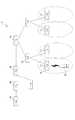
本発明の第1実施形態にかかるパケット通信システム1について添付の図面を参照して説明する。図1はパケット通信システム1の構成を説明する図である。本実施形態にかかるパケット通信システム1は、パケットの送信元のノード(Source Node。以下、本明細書では「SN」と呼ぶ。)10と、パケットを中継する複数の中継ノード(Transit Node。以下、本明細書では「TN」と呼ぶ。)30〜33・・・と、パケットの送信先のノード(Destination Node。以下、本明細書では「DN」と呼ぶ。)50とを備える。これらのSN、TN、DNの間は、有線リンクによって接続されることもでき、無線リンクによって接続されることもできる。
【0042】
SN10は、物理的には、CPU、メモリといった記憶装置、ハードディスクといった格納装置、キーボードやマウスといった入力装置、ディスプレイといった表示装置、通信装置などを備える情報通信可能な通信端末である。また、携帯電話等の移動通信端末であっても良い。
【0043】
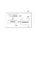
図2は、SN10の機能的な構成を説明するブロック図である。図2に示すように、SN10は、機能的には、経路設定部(経路設定手段)11、経路情報格納部(経路情報格納手段)13と、パケット送信部(パケット送信手段)15とを備えて構成される。
【0044】
経路設定部11は、SN10からDN50にパケットを送信するために、RHOをパケットに付加し、経路情報格納部13に格納された経路情報から、このパケットが経由すべきTNのアドレスをRHOに設定する。ここで、以下の通信で用いられるIPv6のパケットのフォーマットを図3を用いて説明する。図3に示すように、「Version」フィールドから「宛先アドレス格納領域(Destination Address)」までの領域がIPv6のヘッダ(第1のヘッダ)である。このヘッダの「Next Header」フィールドには、次に続くヘッダのタイプを識別するための情報が指定される。本実施形態において、「Next Header」には、次に続く拡張ヘッダとして「RHO」がこのパケットに含まれる旨が指定されているものとする。ここで、図3においては、上述したIPv6のヘッダに後続する「Next Header」フィールドから「Address:N」フィールドまでの領域が、RHO(第2のヘッダ)である。このRHOにおける「Next Heder」フィールドには、RHOに続くヘッダのタイプを識別する情報が格納される。「Hrd Ext Len」には、RHOのサイズが指定される。「Routing Type」には、このRHOのタイプが指定され、IPv6の通常のRHOにおいては、「0」が指定される。「Segments Left」には、このパケットが以降に経由するノードの数が指定される。本明細書では、このRHOにおけるAddress:1〜Nまでの領域を経由アドレス格納領域と呼ぶ。
【0045】
次に、経路情報格納部13について説明する。経路情報格納部13は、SN10から目的のDNまでを中継するTNの経路情報が格納されたデータベースである。このデータベースに格納される経路情報は、例えば、パケットにRRH(Reverse Routing Header)を設けて、SN10から目的のDNまでパケットを送信すると、このパケットを中継するTNが自己のアドレスをパケットに付与しつつパケットを送信するので、このパケットを受信したDNでは、SN10からDNまでの経路情報が得られる。この経路情報がDNからSN10に報告されることによって、経路情報が得られる。
【0046】
経路設定部11は、このように経路情報格納部に格納された経路情報によって、SN10からDN50までのTNの経路をパケットに付与する。図4(a)に図1の例にしたがい、経路設定部11によって経路が設定されたパケットを示す。経路設定部11は、具体的には、まず、パケットにRHOを付加し、パケットの宛先アドレス格納領域(図4(a)中、「Dst.」フィールド)に、このパケットが最初に経由すべきノードであるTN30のアドレスを格納する。次に、RHOの経由アドレス格納領域(図4(a)中、「Slot1」「Slot2」フィールド)にこのパケットが次以降に経由すべきノードであるTN31、TN32のアドレスをその経由順に格納する。また、経由アドレス格納領域における後尾(図4(a)中、「Slot3」フィールド)に送信先のノードである「DN50」のアドレスを格納する。なお、図4(a)においては、「Src.」フィールドは送信元のノードのアドレスを格納する領域であって、「SN10」のアドレスが設定されている。「Next Header」フィールドには、このパケットにおいて、RHOの後方に続くヘッダのタイプを識別する情報が設定され、「Hrd Ext Len」フィールドには、RHOのサイズが指定される。「Routing Type」には、「5」が指定され、「SegmentsLeft」には、図1の例では、パケットがDN50に受信されるまでに経由するノードの数である「3」が指定される。
【0047】
パケット送信部15は、経路設定部11によって出力されるパケットを送信する。
【0048】
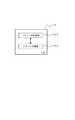
TN30〜32は、SNやDNとの間で行われるパケット通信において、パケットの中継を行うノードである。これらのTNとしては、例えばルータが用いられる。図5は、これらTNの機能的な構成を説明するブロック図である。TN30〜32は、それぞれ機能的には、パケット送受信部(パケット受信手段、第2のパケット送信手段)301、パケット処理部(パケット処理手段)302、経路情報格納部(第2の経路情報格納手段)303を備えて構成される。
【0049】
パケット送受信部301は、SN10や、直前にパケットを中継したTNから送信されるパケットを受信したり、後述するパケット処理部302によって処理されたパケットが次に経由すべきTNや、DNへこのパケットを送信する。
【0050】
パケット処理部302は、パケット送受信部301によって受信されるパケットのRHOの「Routing Type」フィールドに、所定のタイプ情報、例えば、「5」が設定されている場合に、以下のパケット処理を行う。図4(a)〜(d)はそれぞれ、SN10から送信されるパケットが、複数のTNによって中継されるにしたがって、このパケット処理が適用された場合の、パケットを示している。まず、図4(a)に示すパケットを受信したTN30のパケット処理部302は、自己のアドレスとパケットの宛先アドレス格納領域に格納されたアドレスが一致しているか否かを確認する。そして、RHOの経由アドレス格納領域のSlot1に格納されたアドレスをもつTNが、正常に動作しているか否かを判断する。この判断は、TNが次にパケットを経由すべきTNに対して物理的に直接リンクされている場合には、物理層レベルで次にパケットを経由するTNの異常を検出する。また、ICMPなどのネットワーク層のプロトコルによって、次にパケットが経由するTNの異常を検出することもできる。例えば、図4(b1)に示すように、TN30のパケット処理部302は、次にパケットが経由するTN31が正常と判断する場合には、宛先アドレス格納領域をRHOの経由アドレス格納領域のSlot1に格納されたアドレスに書き換える。一方、図4(b2)に示すように、TN30のパケット処理部302は、次にパケットが経由するTN31に異常があって、パケットを中継できない状態にあると判断する場合には、経路情報格納部303から経路情報を取得する。そして、TN30のパケット処理部302は、この経路情報から、TN31の代わりにこのパケットを経由することが可能なTN33のアドレスを割り出して、宛先アドレス格納領域をこのTN33のアドレスで書き換える。そして、パケット処理部302は、このパケットのSlot2から後方のデータをSlot1のサイズ、すなわちIPv6のアドレスのサイズである128ビット、パケットの前方へシフトさせる。このとき、パケット処理部302は、「Segment Left」フィールドを残りの経由数である「2」とし、また、「Hrd Ext Len」フィールドに、以上の処理によって変更されたRHOのサイズを指定する。このようにして、パケット処理部302によって、既に使用済みとなったTN30のアドレスが削除され、パケットのサイズが小さくなる。図4(b1)または図4(b2)に示すパケットを次に中継するTN31またはTN33のパケット処理部302も同様のパケット処理を行い、図4(c)に示すパケットを生成する。図4(c)に示すパケットを次に中継するTN32のパケット処理部302は、自己のアドレスとパケットの宛先アドレス格納領域に格納されたアドレスが一致していることを確認し、また、RHOの経由アドレス格納領域にはSlot1しかないことを確認した上で、Slot1に格納されたアドレス、すなわちDN50のアドレスを、宛先アドレス格納領域に格納し、RHOを削除する。このようにして生成されるパケットは図4(d)となる。このように、パケットがTNを通過するごとに、使用済みとなったアドレスが格納されていた領域が削除されることによって、パケットのサイズが縮小される。また、パケットを最後に中継するTNにおいては、RHO自体を削除するので、更にパケットのサイズが縮小できる。更に、次にパケットを中継するTNに異常がある場合には、パケットを中継するTNの経路を再設定することができる。
【0051】
経路情報格納部303は、SN10の経路情報格納部13と同様に、このTNからDNへパケットを送信するための、経由すべきTNの経路情報を格納するデータベースである。この経路情報格納部303に格納された経路情報は、SN10の経路情報格納部13と同様の処理によって取得できる。また、TN同士が互いに経路情報を交換し合うことによって、経路情報を取得することもできる。
【0052】
DN50は、SN10から送信されるパケットの送信先であって、物理的には、SN10と同様に、CPU、メモリといった記憶装置、ハードディスクといった格納装置、キーボードやマウスといった入力装置、ディスプレイといった表示装置、通信装置などを備える情報通信可能な通信端末である。
【0053】
図6はDN50の機能的な構成を説明するブロック図である。図6に示すように、DN50は、機能的にはパケット受信部51を備える。パケット受信部51は、SN1から送信されて、複数のTNによって中継されるパケットを受信する。なお、DN50は、SN10と同様なパケットの送信元のノードとなることもでき、その場合には、SN10と同様の上述した機能的な構成要素を備えることができる。また、逆にSN10も、DN50となることができ、この場合にSN10は、DN50と同様の上述した機能的な構成要素を備えることができる。
【0054】
以下、本実施形態にかかるパケット通信システム1の動作について説明し、本実施形態にかかるパケット通信方法について説明する。図7は、本実施形態にかかるパケット通信方法のフローチャートである。本実施形態にかかるパケット通信方法では、SN10の経路設定部11が上述したように、宛先アドレス格納領域に、次にこのパケットが経由すべきTNのアドレスを設定する。図1及び図4(a)に示した例では、宛先アドレス格納領域にはTN30のアドレスが設定される。そして、このパケットにRHOを付加し、RHOにこのパケットが2番目以降に経由するTNのアドレスをその経由順に設定し、RHOの後尾にDN50のアドレスを設定する(ステップS101)。図1及び図4(a)に示した例では、TN31、TN32、DN50の順にそのアドレスがRHOに設定される。このように経路が設定されたパケットを、SN10のパケット送信部15は次にパケットを中継するTNに送信する(ステップS102)。図1及び図4(a)に示した例では、SN10はパケットをTN30に送信する。
【0055】
次に、SN10から送信されたパケットを中継するTNのパケット送受信部301が受信する(ステップS103)。そして、パケット処理部302が、パケット送受信部301によって受信されたパケットのRHOにおけるSlot1に格納されたアドレスをもつTNが正常に動作しているかを判断する(ステップS104)。図1及び図4(a)に示した例では、TN31が正常に動作しているか否かを判断する。このとき、Slot1に格納されたアドレスをもつTN、すなわち、次にパケットを中継するTNが正常に動作している場合には、パケット処理部302は、パケットの宛先アドレス格納領域をSlot1に格納されたアドレスに書き換える(ステップS105)。図1及び図4(a)に示した例では、TN31のアドレスが宛先アドレス格納領域に書き込まれる。一方、Slot1にアドレスが格納された次にパケットを中継するTNに異常がある場合、パケット処理部302は、経路を再設定して、宛先アドレス格納領域に再設定したTNのアドレスを書き込む(ステップS106)。図1及び図4(a)に示した例では、TN33のアドレスが書き込まれる。
【0056】
次に、パケット処理部302はパケットを次に中継するTNがないか、すなわち次にパケットが送信されるのは、DN50であるか否かを判断する(ステップS107)。この判断は、RHOの経由アドレス格納領域にSlot1のみしかないこと、または、RHOの「Segments Left」フィールドに格納された数によって判断できる。そして、このパケットを中継するTNがある場合に、パケット処理部302は、パケットのSlot2から後方のデータをSlot1のサイズ分、すなわち128ビット、前方へシフトする(ステップS108)。このとき、RHOの「Segments Left」や「Hrd Ext Len」等のフィールドに格納された情報も変更する。そして、TNのパケット送受信部301は、このパケットを次に中継するTNに送信する(ステップS109)。このように送信されるパケットを次に中継するTNでは、パケットを受信するステップS103からの処理を繰り返す。
【0057】
一方、そのTN以降にパケットを中継するTNはなく、次にパケットが送信されるのはDN50である場合、パケット処理部302は、このパケットに付加されたRHOを削除するとともに、パケットの「Next Header」フィールドに書き込まれたRHOを指定する旨の情報を書き換える(ステップS110)。例えば、パケットに含まれる次のヘッダがTCPヘッダの場合、TCPヘッダを識別するタイプ情報を「Next Header」フィールドに格納する。
【0058】
このように設定されたパケットをTNのパケット送受信部301がDN50に送信し(ステップS111)、DN50のパケット受信部51がこのパケットを受信する(ステップS112)。
【0059】
以下、本実施形態にかかるパケット通信システム1の作用及び効果を説明する。それぞれのTNのパケット処理部302は、以下のパケット処理を行う。すなわち、受信したパケットの宛先アドレス格納領域に、RHOの経由アドレス格納領域のSlot1に格納されたアドレスを格納する。また、このパケットの経由アドレス格納領域におけるSlot2以降のデータを、Slot1のサイズ分、前方へシフトする。これによって、TNを経由する度に、既に不要となったアドレス分のサイズが削減されたパケットを送信できるので、RHOによってパケットが中継される経路を設定しつつ、パケットのサイズを小さくして、ネットワークに与える負荷を抑制することが可能となる。また、DN50に受信されるパケットには、TNのアドレスが含まれないので、SN10によって設定されるTNの経路、すなわちネットワークトポロジを秘匿化することができるので、セキュリティを高めることができる。
【0060】
また、SN10は、パケットに付加したRHOの「Routing Type」フィールドに、所定のタイプ情報を設定する。それぞれのTNにおいては、この所定のタイプ情報が「Routing Type」フィールドに設定されている場合にのみ、上記したパケット処理を実行する。したがって、上記したパケット処理を各TNにおいて柔軟に適用することができる。
【0061】
また、パケットを最後に中継するTNは、パケットにおけるRHOが設定された領域より後方のデータを、RHOのサイズ分前方へシフトする。すなわち、RHOを削除する。したがって、更にパケットのサイズを小さくできるので、ネットワークに与える負荷をさらに抑制することができる。
【0062】
また、それぞれのTNは、経由アドレス格納領域のSlot1に格納されたアドレスをもつ次にパケットを中継するTNが、パケットを中継できないと判断する場合に、経路情報格納部303に格納された経路情報を取得して、このパケットを中継可能なTNを特定して、特定されたTNのアドレスをパケットの宛先アドレス格納領域に格納する。したがって、パケットを中継するTNに異常が生じても、他のTNに経路を切り替えて、パケットを中継できるので、このパケットを途切れることなくDN50に送信できる。また、パケットに経路として設定されたTNが、このパケットを中継できない状態にある場合に、SN10からパケット再送するのではなく、このパケットを直前に中継するTNが、経路を再設定して、パケットを中継するので、パケットの中継に要するタイムラグを少なくできる。
【0063】
(第2実施形態)
【0064】
次に、本発明の第2実施形態にかかるパケット通信システム2について説明する。図8は、第2実施形態にかかるパケット通信システム2の構成を示す図である。図8に示すように、パケット通信システム2は、SN10と、TN40〜44・・・と、DN60を備える。
【0065】
SN10は、物理的には、CPU、メモリといった記憶装置、ハードディスクといった格納装置、キーボードやマウスといった入力装置、ディスプレイといった表示装置、通信装置などを備える情報通信可能な通信端末である。また、携帯電話等の移動通信端末であっても良い。
【0066】
また、SN10は、機能的には第1実施形態に示したSN10と同様の経路設定部11、経路情報格納部13、パケット送信部15を備える。ここで、SN10がこの第2実施形態でパケットを送信する送信先のDN60は移動通信端末である。したがって、DN60は移動するため、DN60にパケットを中継するTNの経路情報をSN10は特定できない。したがって、SN10の経路設定部11は、この第2実施形態の場合には、宛先アドレス格納領域にDN60のアドレスが設定され、RHOが付加されていないパケットを送信する。
【0067】
DN60は、上述したように携帯電話等のパケット通信可能な移動通信端末である。図8において、DN60は、TN44のエリア内に存在し、TN44と通信を行う。DN60は、第1実施形態に示したDN50と同様のパケット受信部を備える。
【0068】
TN42は、移動通信網を他のネットワークに接続するゲートウェイである。また、TN43は、TN42の配下の交換局である。また、TN44は、移動通信端末60の存在する地域のエリアの通信をうけもつ基地局である。これらTN42〜43は、図10に示すように、それぞれ第1実施形態で説明したTN30〜33が備えるパケット送受信部301、パケット処理部302及び経路情報格納部303と、夫々同様の、パケット送受信部411、パケット処理部412及び経路情報格納部413を備えて構成される。
【0069】
TN40は、SN10から送信されるパケットを最初に中継する中継ノードである。TN40には、例えばルータを用いることができる。図9は、TN40の機能的な構成を説明するブロック図である。図9に示すように、TN40は、機能的には、パケット送受信部401と、経路設定部402と、経路情報格納部403とを備えて構成される。
【0070】
パケット送受信部401は、SN10から送信されるパケットを受信し、また、経路設定部402によって処理されたパケットを次に経由すべきTNに送信する。
【0071】
経路設定部402は、このTN40からパケットをDN60に送信するためにこのパケットが経由するTNの経路情報を取得する。この経路情報は、例えば、DN60にパケットを送信するための経路情報をTN42に対して問い合わせることによって得られる。このとき、TN40から経路情報の問い合わせを受けたTN42は、ロケーションレジスタからDN60の位置情報を特定して、この位置情報からDN60にパケットを中継するためのTNの経路情報を決定し、この経路情報をTN40に送信する。経路設定部402は、このようにして得られる経路情報をメモリ又はハードディスク上に構築された経路情報格納部403に格納する。そして、宛先アドレス格納領域に格納されたアドレスを一時的に記憶し、経路情報格納部403に格納された上記の経路情報を参照して、TN40の次にパケットを中継するTNのアドレスをパケットの宛先アドレス格納領域に格納する。図8に示した構成のネットワークでは、TN41のアドレスを宛先アドレス格納領域に格納する。次いで、このパケットにRHOを付加し、RHOの経由アドレス格納領域のSlot1から順に、TN41以降にこのパケットを中継するTNのアドレスを経由順に格納する。最後に、経由アドレス格納領域の後尾に、一時的に記憶したアドレス、すなわちDN60のアドレスを格納する。また、RHOの「Routing Type」フィールドに所定のタイプ情報、例えば「5」を設定し、「Segment Left」フィールドには、このパケットを中継するTNの数を、「Hrd Ext Len」にRHOのサイズを、それぞれ設定する。
【0072】
次に、第2実施形態にかかるパケット通信システム2の動作を説明し、併せて第2実施形態にかかるパケット通信方法について説明する。図11は第2実施形態にかかるパケット通信方法のフローチャートである。図11に示すように、パケット通信システム2においては、まず、SN10が、DN60のアドレスをパケットの宛先アドレス格納領域に格納して、TN40にこのパケットを送信する(ステップS201)。次にTN40のパケット送受信部401がSN10によって送信されるパケットを受信する(ステップS202)。次に、TN40の経路設定部402は、上述したように、パケット送受信部401によって受信されたパケットを、DN60に送信するための経路情報を取得する。そして、このパケットにRHOを付加し、このパケットの宛先アドレス格納領域及びRHOの経由アドレス格納領域に、この経路情報を参照してTN41〜44のアドレスを上述したように設定する(ステップS203)。このパケットをTN40のパケット送受信部411が、TN41に送信する(ステップS204)。
【0073】
次に、TN41のパケット送受信部411が、TN40によって送信されるパケットを受信する(ステップS205)。そしてTN41のパケット処理部412は、パケット送受信部411によって受信されたパケットのRHOにおけるSlot1に格納されたアドレスをもつTNが正常に動作しているか否かを判断する(ステップS206)。すなわち、図8に示したネットワークの場合、TN41の動作を確認する。このとき、Slot1に格納されたアドレスをもつTN、すなわち次にパケットを中継するTNが正常に動作している場合には、パケット処理部412は、パケットの宛先アドレス格納領域をSlot1に格納されたアドレスに書き換える(ステップS207)。一方、Slot1に格納されたアドレスをもつTNに異常がある場合、パケット処理部412は、経路を再設定して、宛先アドレス格納領域に再設定したTNのアドレスを書き込む(ステップS208)。なお、図8においては、DN60までの経路を再設定するための別のルートを構成するTNは省略されている。
【0074】
次に、パケット処理部412はパケットを次に中継するTNがないか、すなわち次にパケットが送信されるのは、DN60であるか否かを判断する(ステップS209)。そして、次にこのパケットを中継するTNがある場合に、パケット処理部412は、パケットのSlot2から後方のデータをSlot1のサイズ分、すなわち128ビット、前方へシフトする(ステップS210)。このとき、RHOの「Segments Left」や「Hrd Ext Len」等のフィールドに格納された情報も変更する。そして、TNのパケット送受信部301は、このパケットを次に中継するTNに送信する(ステップS211)。このように送信されるパケットを次に中継するTNであるTN42〜44ではそれぞれ、パケットを受信するS206からの処理を繰り返す。
【0075】
一方、そのTN以降にパケットを中継するTNはなく、次にパケットが送信されるのはDNである場合、パケット処理部412は、このパケットに付加されたRHOを削除するとともに、パケットの「Next Header」フィールドに書き込まれたRHOを指定する旨の情報を書き換える(ステップS212)。例えば、パケットに含まれる次のヘッダがTCPヘッダの場合、TCPヘッダを識別するタイプ情報を「Next Header」フィールドに格納する。
【0076】
このように設定されたパケットをTNのパケット送受信部411がDNに送信し(ステップS213)、DN60のパケット受信部がこのパケットを受信する(ステップS213)。
【0077】
以下、本実施形態にかかるパケット通信システム2の作用及び効果を説明する。この第2実施形態にかかるパケット通信システム2は、第1実施形態にかかるパケット通信システム1が有する作用効果に加えて、以下の作用効果を有する。パケット通信システム2においては、SN10が送信するパケットの送信先であるDN60は、移動通信端末であるために、このDN60が接続するTNが移動に伴って変化する。したがって、SN10は、DN60までのTNの経路を特定できない。そこで、SN10は、RHOを付加せず、宛先アドレス格納領域にDN60のアドレスを格納したパケットをTN40に送信する。TN40の経路設定部402は、移動通信網のゲートウェイであるTN42に対して、DN60へパケットを中継するためのTNの経路を問い合わせることによって、上述した経路情報を取得する。そして、TN40の経路設定部402は、SN10から送信されたパケットにRHOを設け、上記の経路情報を参照して、パケットの宛先アドレス格納領域及びRHOの経由アドレス格納領域に、パケットを中継する順にTNのアドレスを格納し、経由アドレス格納領域の後尾にDN60のアドレスを格納する。このようにして、経路となるTNのアドレスが設定されたパケットをTN41〜44が中継してDN60に送信する。このように、パケット通信システム2においては、DN60へパケットを送信する際の経路となるTNの経路情報が特定できない場合にも、SN10に接続するTN40によって、パケットに経路となるTNのアドレスを設定することができる。
【0078】
(第3実施形態)
【0079】
次に、本発明の第3実施形態にかかるパケット通信システム3について添付の図面を参照して説明する。図12は、パケット通信システム3の構成を示す図である。パケット通信システム3は、SN10、SN10によって送信されるパケットを中継するTN70とTN72、使用済みアドレスを削除可能な中継ノード(TN)74、及びDN80を備える。
【0080】
本実施形態では、SN10からTN74までの間は有線リンクによって接続されており、TN74とDN80との間は、無線リンクによって接続されている。無線リンクとしては、例えば、無線LANが例示される。
【0081】
SN10は、第1実施形態のSN10と同様の構成を有する。SN10は、パケットをDN80に送信するために、RHOをパケットに付加し、このパケットが経由すべきTNのアドレス及びDNのアドレスをRHOに設定する。
【0082】
図16(a)は、SN10によって送信されるパケットの例である。SN10からDN80までの経路が図12に示される形態である場合には、SN10は、図16(a)に示されるように、「Src.」フィールドに自己のアドレスを格納する。そして、SN10は、「Dst.」フィールド(宛先アドレス格納領域)にパケットが最初に経由すべきTN70のアドレスを格納する。
【0083】
また、SN10は、RHOにおける「Type」フィールドに、所定のタイプ情報として「5」を格納し、「Segm.Left」フィールド(経由ノード数格納領域)にこのパケットが次以降に経由すべきノードの数である3を設定する。さらに、SN10は、「Slot1」、「Slot2」、「Slot3」フィールド(経由アドレス格納領域)に、SN10が次以降に経由するTN72、TN74、DN80のアドレスをそれぞれ格納する。
【0084】
TN70及びTN72は、IPv6に準拠したパケットの中継を行う中継ノードであり、SN10によって送信されるパケットを次に経由すべきTNに中継する。TN70及び72としては、例えばルータが例示される。TN70及びTN72は、機能的には同様の構成を有するので、以下、TN70について説明する。
【0085】
図13は、TN70の機能的な構成を示す図である。TN70は、パケット送受信部700と、パケット処理部702とを有する。
【0086】
パケット送受信部700は、他のノードから送信されたパケットを受信して、パケット処理部702に出力する。また、パケット送受信部700は、パケット処理部702によって処理されたパケットを、その「Dst.」フィールドに格納されているアドレスをもつノードに送信する。
【0087】
パケット処理部702は、パケット送受信部700によって出力されたパケットの「Segm.Left」フィールドを参照して、このパケットが次に経由されるべき中継ノードのアドレスが格納されたSlotを特定する。パケット処理部702は、特定したSlotに格納されたアドレスを、次にそのパケットが経由すべきノードであるとして、「Dst.」フィールドに格納する。そして、パケット処理部702は、自装置のアドレスを上記のように特定したSlotに格納する。パケット処理部702は、このように処理したパケットを、パケット送受信部700に出力する。
【0088】
図16(b)は、TN70によって送信されるパケットの例であり、図16(c)は、TN72によって送信されるパケットの例である。SN10からDN80までの経路が図12に示される形態である場合には、TN70のパケット処理部702は、SN10から送信されたパケット(図16(a)参照)を取得すると、そのパケットの「Segm.Left」フィールドを参照する。図16(a)に示されるパケットの「Segm.Left」フィールドには、「3」が格納されているので、TN70のパケット処理部702は、そのパケットの最終のSlotであるSlot3から前方へ3つめのSlot1が次に経由すべきノードのアドレスが格納されたSlotであることを特定する。TN70のパケット処理部702は、特定したSlot1に格納されているアドレスを「Dst.」フィールドに格納し、自己のアドレスをSlot1に格納し、「Segm.Left」フィールドに格納された数を1減算して「2」とする。以上の処理によって、TN70のパケット処理部702は、図16(b)に示されるパケットを生成する。
【0089】
TN72のパケット処理部702は、は、TN70から送信されたパケット(図16(b)参照)を取得すると、そのパケットの「Segm.Left」フィールドを参照する。図16(b)に示されるパケットの「Segm.Left」フィールドには、「2」が格納されているので、TN72のパケット処理部702は、そのパケットの最終のSlotであるSlot3から前方へ2つめのSlot2が次に経由すべきノードのアドレスが格納されたSlotであると特定する。TN72のパケット処理部702は、特定したSlot2に格納されているアドレスを「Dst.」フィールドに格納し、自己のアドレスをSlot2に格納し、「Segm.Left」フィールドに格納された数を1減算して「1」とする。以上の処理によって、TN72のパケット処理部702は、図16(c)に示されるパケットを生成する。
【0090】
TN74は、他のノードによって送信されたパケットを受信すると、そのパケットが既に経由したノードのアドレスを使用済みであると判断して、使用済みのアドレスを削除する。
【0091】
図14は、TN74の機能的な構成を示す図である。TN74は、機能的には、パケット送受信部(パケット受信手段、パケット送信手段に相当する)740と、パケット処理部(パケット処理手段)742とを有する。
【0092】
パケット送受信部740は、他のノードから送信されたパケットを受信して、パケット処理部702に出力する。また、パケット送受信部700は、パケット処理部742によって処理されたパケットを、その「Dst.」フィールドに格納されているアドレスをもつノードに送信する。
【0093】
パケット処理部742は、上述したように使用済みのアドレスを削除するパケット処理を行う部分である。このパケット処理についてより具体的に説明すると、まず、パケット処理部724は、パケット送受信部740から出力されたパケットの「Segm.Left」フィールドを参照して、自装置が最終の中継ノードであるか否かを判断する。すなわち、「Segm.Left」フィールドに格納された数値が「1」である場合に、パケット処理部724は、自装置が最終の中継ノードであると判断する。一方、「Segm.Left」フィールドに格納された数値が「1」より大きい場合に、パケット処理部724は、自装置は最終の中継ノードでない、すなわち、他にこのパケットを中継するノードがあると判断する。
【0094】
パケット処理部724は、自装置が最終の中継ノードであると判断する場合には、最終のSlotに格納されたアドレスを「Dst.」フィールドに格納する。そして、パケット処理部724は、RHOより後方のパケットのデータをRHOの容量分前方にシフトすることによって、RHOを削除する。
【0095】
一方、パケット処理部724は、自装置が最終の中継ノードでないと判断する場合には、パケット送受信部740から出力されたパケットの「Segm.Left」フィールドを参照して、このパケットが次に経由されるべき中継ノードのアドレスが格納されたSlotを特定する。パケット処理部742は、特定したSlotに格納されているアドレスを「Dst.」フィールドに格納する。そして、パケット処理部742は、特定したSlotより後方のパケットのデータを、特定したSlotから最前のSlotまでの容量分、前方へシフトする。すなわち、パケット処理部742は、特定したSlotから最前のSlotまでのSlotに格納されたアドレスは既に経由したノードのアドレスであると判断して、これらのSlotに格納されているアドレスを削除する。さらに、パケット処理部742は、「Segm.Left」フィールドに格納された数から1を減算する。
【0096】
図16(d)は、TN74によって送信されるパケットの例を示す図である。SN10からDN80までの経路が図12に示される形態である場合に、パケット処理部742は、TN72によって送信されたパケット(図16(c)参照)を取得すると、「Segm.Left」フィールドに格納された数値が「1」であることから、自装置が最終の中継ノードであると判断する。そして、パケット処理部742は、最終のSlotであるSlot3に格納されたDN80のアドレスを「Dst.」フィールドに格納する。さらに、パケット処理部742は、RHOより後方のパケットのデータをRHOの容量分前方にシフトすることによって、図16(d)に示されるパケットを生成する。
【0097】
DN80は、SN10によって送信されたパケットの送信先のノードである。DN80は、本実施形態では、TN74と無線リンクを介して接続されている。DN80としては、例えば無線LANのためのLANカードが搭載されたパーソナルコンピュータ、無線LAN機能を内蔵した携帯電話といった移動通信端末が例示される。
【0098】
図15は、DN80の機能的な構成を示す図である。図15に示されるように、DN80は、パケット受信部800を有している。パケット受信部800は、他のノードから送信されたパケットを受信する部分である。
【0099】
以下、パケット通信システム3の動作を説明し、併せて本発明の第3実施形態にかかるパケット通信方法について説明する。図17は、第3実施形態にかかるパケット通信方法のフローチャートである。
【0100】
図17に示すように、本実施形態のパケット通信方法によれば、まず、SN10によってパケットにRHOが付加され、パケットの「Dst.」フィールドに次に経由すべきノードのアドレスが格納される。そして、SN10によって、上述したようにRHOの「Type」フィールド、「Segm.Left」フィールドが設定され、Slotに経由順にノードのアドレスが格納される(ステップS301)。SN10は、このように設定されたパケットを「Dst.」フィールドにアドレスが格納されたノードに送信する(ステップS302)。
【0101】
次いで、上述したTN70及びTN72のごとき中継ノードによってパケットが処理されると共に中継され(ステップS303)、使用済みアドレス削除可能なTN74がそのパケットを受信する(ステップS304)。
【0102】
TN74では、パケット送受信部740が受信したパケットをパケット処理部742に出力し、パケット処理部742がそのパケットの「Segm.Left」フィールドを参照することによって、上述したように自装置が最終の中継ノードであるか否かを判断する(ステップS305)。すなわち、パケット処理部742は、「Segm.Left」フィールドが「1」である場合には、自装置が最終の中継ノードであると判断し、「Segm.Left」フィールドが「1」より大きい場合には、他にこのパケットを中継すべき中継ノードがあるものと判断する。
【0103】
パケット処理部742は、自装置が最終の中継ノードであると判断する場合には、このパケットの送信先のノードであるDN80のアドレスを、「Dst.」フィールドに格納する(ステップS306)。すなわち、パケット処理部742は、最終のSlotに格納されているアドレスを「Dst.」フィールドに格納する。そして、パケット処理部742は、RHOのサイズ分RHOの後方のデータをパケットの前方へシフトすることによって、RHOを削除する(ステップS307)。
【0104】
パケット処理部742は、以上の処理を施したパケットをパケット送受信部740に出力し、パケット送受信部740はパケット処理部742によって出力されたパケットを「Dst.」フィールドにアドレスが格納されたDN80に送信する(ステップS308)。
【0105】
一方、ステップS305の条件分岐において、自装置が最終の中継ノードでないと判断する場合には、パケット処理部742は、「Segm.Left」フィールドに格納された数を参照し、この数から次にこのパケットが経由されるべき中継ノードのアドレスが格納されたSlotを特定する。パケット処理部742は、特定したSlotに格納されたアドレスを、「Dst.」フィールドに格納する(ステップS309)。そして、パケット処理部742は、特定したSlotより後方のパケットのデータを、特定したSlotから最前のSlotまでの容量分、前方へシフトする(ステップS310)。さらに、パケット処理部742は、「Segm.Left」フィールドに格納された数から1を減算する(ステップS311)。
【0106】
パケット処理部742は、以上の処理を施したパケットをパケット送受信部740に出力し、パケット送受信部740はパケット処理部742によって出力されたパケットを「Dst.」フィールドにアドレスが格納されたTNに送信する(ステップS312)。そして、TN74によって送信されたパケットを受信したTNが、そのパケットを上述したTN70や72の如く中継する(ステップS313)。
【0107】
以上のように、中継ノードを経由したパケットが、最後に、DN80によって受信される(ステップS314)。
【0108】
以下、本実施形態にかかるパケット通信システム3の作用及び効果について説明する。パケット通信システム3には、使用済みアドレスを削除可能なTN74が含まれており、TN74によって、既に経由した中継ノードのアドレスが格納された領域が、パケットの後方のデータによって上書きされる。したがって、TN74によって受信されたパケットは、TN74によって、少なくともかかる領域分の容量が削減されたパケットとされる。このように、TN74によって、パケットのサイズが小さくされ、このパケットの通信が行われるネットワークの負荷が低減される。特に、無線リンクは、その帯域が狭いので、無線リンクに接続されるノードとして、使用済みアドレスを削除可能なTN74は好適である。
【0109】
また、本実施形態のパケット通信システム3は、既に経由したアドレスが格納されているパケットの領域を削除する機能を全ての中継ノードに設けなくとも、使用済みアドレスを削除可能なTN74を無線リンクと接続するといったように適切な個所に柔軟に配置することによって、ネットワークの負荷が低減される。したがって、本実施形態のパケット通信システム3は、第1及び第2実施形態のパケット通信システムと比較して、最小限の機能拡張によってネットワークリソースの有効活用を図ることができる。
【0110】
また、TN74は、RHOに所定のタイプ情報が設定されている場合、すなわち、「Type」フィールドに「5」が格納されている場合のみ、上述したパケット処理を行うので、このパケット処理を柔軟に適用することができる。
【0111】
【発明の効果】
以上説明したように、本発明によれば、送信元のノードから送信先のノードにパケットを中継する中継ノードが、パケットを受信した場合に、そのパケットの宛先アドレス格納領域に、第2のヘッダに含まれる経由アドレス格納領域の先頭に格納されたアドレスを格納する。また、経由アドレス格納領域において、ノードのアドレスが格納された先頭の領域より後方のパケットのデータを、1つのアドレスのサイズに相当する分だけ、前方へシフトする。これによって、中継ノードによって中継される度に、既に不要となったアドレス分のサイズが削減されたパケットを送信できるので、第2のヘッダよってパケットが中継される経路を設定しつつ、パケットのサイズを小さくして、ネットワークに与える負荷を抑制することが可能となる。
【0112】
また、本発明によれば、使用済みアドレスを削除可能な中継ノードに受信されたパケットは、該中継ノードによって既に経由したノードのアドレスが削除されサイズが縮小されたパケットとされるので、このパケットを中継するネットワークに与える負荷が抑制される。
【図面の簡単な説明】
【図1】図1は、第1実施形態にかかるパケット通信システムの構成を示す図である。
【図2】図2は、SNの機能的な構成を示すブロック図である。
【図3】図3は、IPv6のパケットを説明する図である。
【図4】図4(a)は、SNによって送信されるパケットの例である。
図4(b1)は、TNによって中継されるパケットの例である。
図4(b2)は、TNによって中継されるパケットの例である。
図4(c)は、TNによって中継されるパケットの例である。
図4(d)は、TNによって中継されるパケットの例である。
【図5】図5は、第1実施形態にかかるTNの機能的な構成を示すブロック図である。
【図6】図6は、第1実施形態にかかるDNの機能的な構成を示すブロック図である。
【図7】図7は、第1実施形態にかかるパケット通信方法のフローチャートである。
【図8】図8は、第2実施形態にかかるパケット通信システムの構成を示す図である。
【図9】図9は、第2実施形態にかかるTNの機能的な構成を示すブロック図である。
【図10】図10は、第2実施形態にかかるSNからのパケットを第1に経由するTNの機能的な構成を示すブロック図である。
【図11】図11は、第2実施形態にかかるパケット通信方法のフローチャートである。
【図12】図12は、第3実施形態にかかるパケット通信システムの構成を示す図である。
【図13】図13は、中継ノードの機能的な構成を示す図である。
【図14】図14は、使用済みアドレスを削除可能な中継ノードの機能的な構成を示す図である。
【図15】図15は、送信先のノードの機能的な構成を示す図である。
【図16】図16(a)は、SNによって送信されるパケットの例を示す図である。
図16(b)は、中継ノードによって中継されるパケットの例を示す図ある。
図16(c)は、中継ノードによって中継されるパケットの例を示す図である。
図16(d)は、使用済みアドレスを削除可能な中継ノードによって中継されるパケットの例を示す図である。
【図17】図17は、第3実施形態にかかるパケット通信方法のフローチャートである。
【符号の説明】
1,2,3…パケット通信システム、10…SN、11…経路設定部、13…経路情報格納部、15…パケット送信部、30〜33,40〜44,70〜74…TN、301…パケット送受信部、302…パケット処理部、303…経路情報格納部、401…パケット送受信部、402…経路設定部、403…経路情報格納部、411…パケット送受信部、412…パケット処理部、413…経路情報格納部、740…パケット送受信部、742…パケット処理部、50…DN、51…パケット受信部、60…DN(移動通信端末)、80…DN。[0001]
TECHNICAL FIELD OF THE INVENTION
The present invention relates to a packet communication system.
[0002]
[Prior art]
IPv6 has recently become widespread as a packet communication protocol. According to this IPv6, when a packet is transmitted from a transmission source node (for example, a transmission terminal such as a personal computer) to a transmission destination node (for example, a transmission terminal such as a personal computer), a relay node (via which the packet passes) is transmitted. For example, a routing header (Routing Header; hereinafter, referred to as “RHO” in the present specification) that specifies the address of a router (transmission source node) can be added as an extension header (for example, Non-Patent Document 1). reference). In IPv6, by providing this RHO, a route of a relay node through which a packet passes can be set.
[0003]
[Non-patent document 1]
Internet Society, "Internet Protocol, Version 6 (IPv6) Specification", 4.4 Routing Header Page. 12, [online], December 3, 1998, <URL: http: // www. ief. org / rfc / rfc2460. txt>
[0004]
[Problems to be solved by the invention]
However, in the above-mentioned IPv6, when a source node adds an RHO to a packet, the packet is relayed to a destination node while the packet size remains unchanged, and a large-sized packet exerts a heavy load on a network. .
[0005]
The present invention has been made in order to solve the above problems, and it is possible to add a RHO while suppressing a load on a network, to delete a packet communication system, a node, a relay node, and a used address. It is an object to provide a relay node and a packet communication method.
[0006]
[Means for Solving the Problems]
In order to solve the above problems, a packet communication system according to the present invention includes a first header including a destination address storage area for storing an address of a destination node, and stores addresses of one or more relay nodes serving as paths. A packet communication system for transmitting a packet to which a second header having an address storage area can be added from a source node to a destination node via one or more relay nodes, wherein the source node is Path information storage means for storing path information indicating a path of a relay node through which the packet passes for transmitting the packet to the destination node; and the path information stored in the path information storage means. And storing the address of the first relay node through which the packet passes first in the destination address storage area of the packet. And providing the second header in the packet, storing the addresses of the relay nodes through which the packet passes after the first relay node in the transit address storage area in the transit order based on the path information. A route setting unit that stores the address of the destination node at the end of the via address storage area; and a packet transmitting unit that transmits the packet. The relay node includes a packet receiving unit that receives the packet. If the address stored in the destination address storage area of the packet received by the packet receiving means matches the address of the relay node, the address stored at the head of the transit address storage area in the packet Is stored in the destination address storage area, and the Packet processing means for performing packet processing for shifting the data of the packet stored after the head area where the address is stored to the front of the packet by an amount corresponding to one capacity of the address; And a second packet transmitting means for transmitting the packet processed by the processing means.
[0007]
Further, in order to solve the above problem, a relay node according to the present invention includes a first header including a destination address storage area for storing an address of a destination node, and stores addresses of one or more relay nodes serving as paths. The relay node in a packet communication system for transmitting a packet to which a second header having a via address storage area can be added from a source node to a destination node via one or more relay nodes, Receiving means for receiving the packet; and storing the via address in the packet when an address stored in the destination address storage area of the packet received by the packet receiving means matches an address of the relay node. The address stored at the beginning of the area is stored in the destination address storage area, and the Packet processing means for performing packet processing for shifting data of the packet stored after the head area where the address of the storage area is stored, to the front of the packet by an amount corresponding to one capacity of the address; And a second packet transmitting means for transmitting the packet processed by the packet processing means.
[0008]
According to another aspect of the present invention, there is provided a packet communication method including a first header including a destination address storage area for storing an address of a destination node, and storing an address of at least one relay node serving as a path. A packet communication method for transmitting a packet to which a second header having a transit address storage area to which a second header can be added from a source node to a destination node via one or more relay nodes. The path setting means provided in the node transmits the packet stored in the path information storage means to the destination node based on the path information indicating the path of the relay node through which the packet passes, based on the path information of the packet. The destination address storage area stores the address of the first relay node through which the packet first passes, and stores the second address in the packet. And based on the route information, stores the addresses of the relay nodes through which the packet passes after the first relay node in the transit address storage area in the transit order, and stores the addresses in the transit address storage area. A route setting step of storing the address of the destination node, a packet transmitting unit of the source node transmitting the packet, and a packet receiving unit of the relay node transmitting the packet. A packet receiving step for receiving the packet, wherein the packet processing means provided in the relay node determines that an address stored in the destination address storage area of the packet received by the packet receiving means matches an address of the relay node; , The head of the via address storage area in the packet The stored address is stored in the destination address storage area, and the data of the packet stored behind the first area of the via address storage area where the address is stored corresponds to one capacity of the address. A packet processing step of executing a packet process of shifting the packet forward, and a second packet transmitting means for transmitting the packet processed by the packet processing means, wherein the second packet transmitting means of the relay node transmits the packet. And a transmitting step.
[0009]
According to these inventions, in the packet transmitted by the transmission source node, the address of the relay node through which the packet passes first is stored in the destination address storage area of the first header. Further, a second header is added to this packet. In the second header, the address of the relay node through which the packet further passes and the address of the destination node are stored in the order of passage. The relay node that receives such a packet is provided with a packet processing unit that executes the following packet processing. In this packet processing, when the address of the relay node matches the address stored in the destination address storage area of the packet, the address stored at the head of the transit address storage area is stored in the destination address storage area. Further, the data of the packet after the area where the head address in the via address storage area is stored is shifted forward by an amount corresponding to the size of one address. As a result, every time the packet passes through the relay node, a packet whose size has been reduced by the address that is no longer required can be transmitted, and the size of the packet can be reduced while setting the route through which the packet is relayed by the second header. By reducing the size, it is possible to suppress the load on the network.
[0010]
Further, in the packet communication system of the present invention, the route setting means provided in the transmission source node stores predetermined type information in the second header of the packet, and the packet processing means provided in the relay node May perform the packet processing when the predetermined type information is set in the second header of the packet received by the packet receiving unit.
[0011]
Further, the transmission node of the present invention includes a first header including a destination address storage area for storing an address of a destination node, and a transit address storage area for storing addresses of at least one relay node serving as a route. The source node in a packet communication system for transmitting a packet to which a second header can be added from a source node to a destination node via one or more relay nodes. A path information storage unit for storing path information indicating a path of a relay node through which the packet passes to transmit the packet to a node; and the packet based on the path information stored in the path information storage unit. In the destination address storage area, the address of the first relay node through which the packet first passes is stored, and The second header is provided in the packet, predetermined type information is stored in the second header, and based on the route information, the address of the relay node through which the packet passes from the first relay node onward is specified. A route setting unit that stores the address of the destination node at the end of the transit address storage area in the transit address storage area in the transit order, and a packet transmission unit that transmits the packet. Is also good.
[0012]
Further, in the relay node according to the present invention, the packet processing means executes the packet processing when predetermined type information is set in the second header of the packet received by the packet receiving means. It may be characterized by doing.
[0013]
In the packet communication method according to the present invention, in the route setting step, the route setting means provided in the transmission source node stores predetermined type information in the second header of the packet, In the step, the packet processing means included in the relay node executes the packet processing when the predetermined type information is set in the second header of the packet received by the packet receiving means. It may be characterized.
[0014]
According to these inventions, the source node sets the predetermined type information in the second header added to the packet. In the relay node, the above-described packet processing can be executed only when the predetermined type information is set, so that the above-described packet processing according to the present invention can be flexibly applied.
[0015]
Further, in the packet communication system of the present invention, the packet processing means provided in the relay node may include, in the packet processing, an address stored in the destination address storage area of the packet received by the packet receiving means. When it is determined that the addresses of the relay nodes match and that the number of addresses stored in the transit address storage area is one, the address stored in the transit address storage area is stored in the destination address storage area. In addition, it is preferable that data behind the area of the second header of the packet be shifted forward by an amount corresponding to the capacity of the second header.
[0016]
Further, in the relay node of the present invention, the packet processing means may include, in the packet processing, an address stored in the destination address storage area of the packet received by the packet receiving means and an address of the relay node. If it is determined that there is only one address stored in the transit address storage area, the address stored in the transit address storage area is stored in the destination address storage area, and the packet It is preferable that data behind the area of the second header be shifted forward by an amount corresponding to the capacity of the second header.
[0017]
Further, in the packet communication method according to the present invention, in the packet processing step, the packet processing means provided in the relay node includes an address stored in the destination address storage area of the packet received by the packet receiving means. If it is determined that the address of the relay node matches and the address stored in the via address storage area is one, the address stored in the via address storage area is stored in the destination address storage area. It is preferable to store the data and shift the data behind the area of the second header of the packet forward by an amount corresponding to the capacity of the second header.
[0018]
According to the present invention, in the relay node that relays the above-mentioned packet last, data behind the area of the second header of the packet is shifted by an amount corresponding to the capacity of the second header. The capacity of the header itself can be reduced. As a result, the size of the packet can be further reduced, so that the load on the network can be suppressed.
[0019]
Further, in the packet communication system according to the present invention, the relay node includes a second path in which path information indicating a path of the relay node through which the packet passes is stored in order to transmit the packet to the destination node. The information storage device may further include an information storage unit.
[0020]
Further, the relay node according to the present invention further includes a second path information storage unit that stores path information indicating a path of the relay node through which the packet passes in order to transmit the packet to the destination node. It may be characterized.
[0021]
As described above, even in the relay node, the provision of the second path information storage unit in which the path information is stored makes it possible to set the packet path in the relay node as described below.
[0022]
In the packet communication system of the present invention, the packet processing means provided in the relay node may be such that, in the packet processing, the relay node having the address stored at the head of the via address storage area cannot relay the packet. When it is determined that, based on the route information stored in the second route information storage means, the address of the relay node to which the packet should pass next is determined, and the determined address is The data of the packet stored in the destination address storage area and stored after the head area where the address of the transit address storage area is stored is divided by the amount corresponding to one capacity of the address. Is preferably shifted forward.
[0023]
Further, in the relay node of the present invention, the packet processing means, in the packet processing, when the relay node having the address stored at the head of the via address storage area determines that the packet cannot be relayed, Based on the path information stored in the second path information storage means, an address of a relay node to which the packet should pass next is determined, and the determined address is stored in the destination address storage area of the packet. Storing and shifting the data of the packet stored after the head area where the address of the transit address storage area is stored, to the front of the packet by an amount corresponding to one capacity of the address. Is preferred.
[0024]
Further, in the packet communication method according to the present invention, in the packet processing step, the packet processing means provided in the relay node includes a relay node having an address stored at the head of the transit address storage area relaying the packet. If it is determined that the packet cannot be transmitted, the packet is stored in the second path information storage means of the relay node, based on the path information indicating the path of the relay node for transmitting the packet to the destination node. Determines the address of the relay node to be passed next, stores the determined address in the destination address storage area of the packet, and is located behind the first area where the address of the transit address storage area is stored. The data of the packet stored in the It is preferably characterized by shifting forward the packet.
[0025]
According to these inventions, if the relay node having the address stored at the head of the transit address storage area included in the second header of the packet, that is, the node to which the packet is to be relayed next has an abnormality. When it is determined that the packet cannot be relayed, a relay node capable of relaying the packet is determined based on the route information stored in the second route information storage means, and the address of the relay node is set to the packet. In the destination address storage area. Therefore, the packet can be transmitted to the destination node without interruption at the relay node. Also, when a relay node in the middle of a route cannot relay a packet, instead of retransmitting the packet from the source node, the relay node immediately before resets the route and relays the packet. The required time lag can be reduced. Further, in this packet, the first area in which the above address of the transit address storage area is stored is deleted by shifting forward the data behind it, so that the size of this packet can be reduced. As a result, it is possible to reduce the size of the packet while setting the route through which the packet is relayed by the second header, thereby suppressing the load on the network.
[0026]
In the packet communication system according to the present invention, when the relay node determines that the second header is not added to the packet received by the packet receiving unit, the relay node stores the destination address of the packet. The address stored in the area is temporarily stored, the packet is provided with the second header, and based on the path information stored in the path information storage means, the packet is stored next to the relay node. The address of the first relay node to be passed is stored in the destination address storage area, and based on the route information, the addresses of the relay nodes to be passed by the packet after the first relay node are arranged in the order in which the packets are passed. The temporary address is stored in the transit address storage area, and the temporarily stored address is stored at the end of the transit address storage area. It may be characterized in further comprising a second path setting means.
[0027]
Further, in the relay node of the present invention, when it is determined that the second header is not added to the packet received by the packet receiving means, the address stored in the destination address storage area of the packet. And the second header is provided in the packet, and based on the path information stored in the path information storage means, the first packet to be transmitted next to the relay node The address of the relay node is stored in the destination address storage area, and based on the path information, the addresses of the relay nodes to which the packet should pass after the first relay node are stored in the transit address storage area in the order of transit. And a second path setting means for storing the temporarily stored address at the end of the transit address storage area. It may be characterized.
[0028]
Further, in the packet communication method according to the present invention, when the second route setting means provided in the relay node determines that the second header is not added to the packet received by the packet receiving means, Temporarily storing the address stored in the destination address storage area of the packet, providing the packet with the second header, and storing the address stored in the second route information storage means provided in the relay node. Based on the routing information indicating the route of the relay node for transmitting the packet to the destination node, the address of the first relay node to which the packet should pass next to the relay node is stored in the destination address storage area. And stores, based on the route information, an address of a relay node that the packet should pass through after the first relay node, in the order of the route. Stored in the via address storage area, it may be characterized in that the tail of the via address storage area further comprising a second path setting step of storing the address as described above temporarily stored.
[0029]
According to these inventions, when the source node cannot specify the routing information, or when transmitting the packet without specifying the routing information, that is, when transmitting the packet without adding the second header, In the relay node, a second header can be provided in the packet, and the address of the relay node through which the packet passes can be set.
[0030]
Further, in the packet communication system of the present invention, the second route setting means provided in the relay node sets predetermined type information in the second header area of the packet, and is transmitted by the relay node. The packet processing means provided in a relay node through which the packet passes after the relay node performs the packet processing when the predetermined type information is set in the second header of the packet. May be characterized.
[0031]
Further, in the relay node of the present invention, the second route setting means may execute the packet processing by a relay node that relays the packet to the relay node and thereafter. It may be characterized in that predetermined type information is set in the.
[0032]
Further, in the packet communication method according to the present invention, in the second path setting step, the second path setting means provided in the relay node sets predetermined type information in the second header area of the packet. In the packet processing step, the packet processing means provided in the relay node through which the packet transmitted by the relay node passes after the relay node includes the predetermined type information in the second header of the packet. In the case where is set, the packet processing is executed.
[0033]
According to these inventions, when the relay node does not add the second header to the received packet and provides the second header as described above and sets the route of this packet, The predetermined type information is stored in the header. The relay node that relays the packet thus set next performs the above-described packet processing only when the above-mentioned predetermined type information is set in the second header. It can be applied flexibly.
[0034]
According to another aspect of the present invention, there is provided a packet communication system including a first header including a destination address storage area for storing an address of a destination node, and storing addresses of one or more relay nodes serving as paths. A packet to which a second header having a transit address storage area to be transmitted and a transit node number storage area to store the number of transit nodes is transmitted from a transmission source node to a transmission destination via one or more relay nodes. In the packet communication system for transmitting to the nodes, the addresses of the nodes are stored in the via address storage area in the order in which they should be passed by the source node or the relay node that has already passed, and The second header in which the number of nodes to be passed through is stored is added, and the address of the own device is stored in the destination address storage area. Packet receiving means for receiving the received packet, and from the address stored in the via address storage area based on the number of packets received by the packet receiving means stored in the via node number storage area, The address of the node to be extracted is extracted, the address is stored in the destination address storage area, and based on the number stored in the number-of-via-nodes storage area, of the addresses stored in the via address storage area, Packet processing means for performing packet processing for shifting the data of the packet forward by the capacity of the area storing the address of the relay node and reducing the number stored in the number-of-transit-nodes storage area by 1; Packet transmitting means for transmitting the packet processed by the processing means. It is characterized in that it comprises dividing capable relay nodes.
[0035]
In order to solve the above-mentioned problem, a relay node capable of deleting a used address according to the present invention includes a first header including a destination address storage area for storing an address of a destination node, and one or more routes serving as paths. A packet to which a second header having a transit address storage area for storing the address of a relay node and a transit node number storage area for storing the number of nodes to be transited can be added to at least one relay node from a source node. Included in a packet communication system that transmits to a destination node via a relay node that is capable of removing a used address, wherein the source node or the relay node that has already passed, The address is stored in the transit address storage area, and the number of nodes to be transited thereafter is stored in the transit node number storage area. Packet receiving means for receiving the packet in which the address of its own device is stored in the destination address storage area, and the packet received by the packet receiving means is stored in the transit node number storage area. Based on the number, the address of the next node to be passed is extracted from the address stored in the via address storage area, the address is stored in the destination address storage area, and the number stored in the via node number storage area The data of the packet is shifted forward by an amount corresponding to the capacity of the area in which the address of the relay node that has already passed is stored among the addresses stored in the above-mentioned transit address storage area, and is stored in the transit node number storage area. Packet processing means for performing packet processing for reducing the number It is characterized in that it comprises a packet transmitting means for transmitting the packet.
[0036]
According to another aspect of the present invention, there is provided a packet communication method including a first header including a destination address storage area for storing an address of a destination node, and storing an address of at least one relay node serving as a path. A packet to which a second header having a transit address storage area to be transmitted and a transit node number storage area to store the number of transit nodes is transmitted from a transmission source node to a transmission destination via one or more relay nodes. A packet communication method for transmitting to a node, the packet receiving means provided in a relay node capable of deleting a used address, the source node or a relay node that has already passed, the address of the node in the order to be passed Is stored in the via address storage area, and the number of nodes to be subsequently passed is stored in the via node number storage area. A packet receiving step of receiving the packet in which the address of the own device is stored in the destination address storage area, and a packet processing means provided in a relay node capable of deleting the used address, Based on the number of packets received by the receiving means stored in the number-of-transit-nodes storage area, the address of the next node to be passed through is extracted from the address stored in the transit-address storage area and the address is sent to the destination. The address stored in the address storage area, and based on the number stored in the via-node storage area, of the addresses stored in the via-address storage area, the capacity of the area in which the address of the relay node that has already passed is stored. A packet that shifts the data of a packet forward and decreases the number stored in the number-of-transit-nodes storage area by one. A packet processing step of executing processing; and a packet transmission step of transmitting the packet processed by the packet processing means, the packet transmission means provided in the relay node capable of deleting the used address. And
[0037]
According to these inventions, in the packet received by the relay node capable of deleting the used address, the area in which the address of the relay node that has already passed is stored is overwritten by the data behind the packet by the relay node. Therefore, a packet whose capacity for such an area is at least reduced is determined. Therefore, the size of the packet that has passed through the relay node from which the used address can be deleted is reduced, and the load on the network that relays the packet is reduced.
[0038]
In the packet, predetermined type information is stored in the second header by the transmission source node or a relay node that has already passed, and the packet processing means includes a packet in the second header of the packet. It is preferable to execute the packet processing when the predetermined type information is set. Only when such predetermined type information is set in the second header of the packet, the above-described packet processing is executed by the relay node capable of deleting the used address, so that the above-described packet processing is flexibly applied. Is done.
[0039]
BEST MODE FOR CARRYING OUT THE INVENTION
Hereinafter, a packet communication system according to an embodiment of the present invention will be described. In the following description of the embodiments, in order to facilitate understanding of the description, the same components are denoted by the same reference numerals as much as possible in each drawing, and redundant description will be omitted.
[0040]
(1st Embodiment)
[0041]
A
[0042]
The
[0043]
FIG. 2 is a block diagram illustrating a functional configuration of the
[0044]
The
[0045]
Next, the path
[0046]
The
[0047]
The
[0048]
The
[0049]
The packet transmitting / receiving
[0050]
The
[0051]
The route
[0052]
The
[0053]
FIG. 6 is a block diagram illustrating a functional configuration of the
[0054]
Hereinafter, the operation of the
[0055]
Next, the packet transmission /
[0056]
Next, the
[0057]
On the other hand, if there is no TN that relays the packet after the TN, and the next packet is transmitted to the
[0058]
The packet transmitting / receiving
[0059]
Hereinafter, the operation and effect of the
[0060]
Further, the
[0061]
Also, the TN that relays the packet last shifts the data behind the area in the packet where the RHO is set, by the size of the RHO. That is, the RHO is deleted. Therefore, the size of the packet can be further reduced, so that the load on the network can be further reduced.
[0062]
If the TN that relays the next packet having the address stored in
[0063]
(2nd Embodiment)
[0064]
Next, a
[0065]
The
[0066]
The
[0067]
The
[0068]
The
[0069]
The
[0070]
The packet transmitting / receiving
[0071]
The
[0072]
Next, an operation of the
[0073]
Next, the packet transmitting / receiving
[0074]
Next, the
[0075]
On the other hand, if there is no TN that relays the packet after that TN, and the next packet is to be transmitted to the DN, the
[0076]
The packet transmitting / receiving
[0077]
Hereinafter, the operation and effect of the
[0078]
(Third embodiment)
[0079]
Next, a
[0080]
In the present embodiment, the connection from the
[0081]
The
[0082]
FIG. 16A is an example of a packet transmitted by the
[0083]
Also, the
[0084]
The
[0085]
FIG. 13 is a diagram illustrating a functional configuration of the
[0086]
Packet transmitting / receiving
[0087]
The
[0088]
FIG. 16B is an example of a packet transmitted by the
[0089]
Upon acquiring the packet transmitted from the TN 70 (see FIG. 16B), the
[0090]
Upon receiving a packet transmitted by another node, the TN 74 determines that the address of the node through which the packet has already passed has been used, and deletes the used address.
[0091]
FIG. 14 is a diagram illustrating a functional configuration of the TN 74. The TN 74 functionally includes a packet transmitting / receiving unit (corresponding to a packet receiving unit and a packet transmitting unit) 740 and a packet processing unit (packet processing unit) 742.
[0092]
Packet transmitting / receiving
[0093]
The
[0094]
If the packet processing unit 724 determines that the own device is the last relay node, the packet processing unit 724 stores the address stored in the last slot in the “Dst.” Field. Then, the packet processing unit 724 deletes the RHO by shifting the data of the packet behind the RHO by the capacity of the RHO.
[0095]
On the other hand, if the packet processing unit 724 determines that the own device is not the last relay node, the packet processing unit 724 refers to the “Segm. Left” field of the packet output from the packet The slot in which the address of the relay node to be performed is stored is specified. The
[0096]
FIG. 16D is a diagram illustrating an example of a packet transmitted by the TN 74. When the route from the
[0097]
The
[0098]
FIG. 15 is a diagram illustrating a functional configuration of the
[0099]
Hereinafter, the operation of the
[0100]
As shown in FIG. 17, according to the packet communication method of the present embodiment, first, the RHO is added to the packet by the
[0101]
Next, the packet is processed and relayed by a relay node such as TN70 and TN72 described above (step S303), and the TN 74 capable of deleting the used address receives the packet (step S304).
[0102]
In the TN 74, the packet transmission /
[0103]
When judging that the
[0104]
The
[0105]
On the other hand, when it is determined in the conditional branch of step S305 that the own device is not the last relay node, the
[0106]
The
[0107]
As described above, the packet that has passed through the relay node is finally received by the DN 80 (step S314).
[0108]
Hereinafter, the operation and effect of the
[0109]
In addition, the
[0110]
The TN 74 performs the above-described packet processing only when the predetermined type information is set in the RHO, that is, only when “5” is stored in the “Type” field. Can be applied.
[0111]
【The invention's effect】
As described above, according to the present invention, when a relay node that relays a packet from a source node to a destination node receives the packet, the relay node stores the second header in the destination address storage area of the packet. Stores the address stored at the beginning of the via address storage area included in. Also, in the via address storage area, the data of the packet behind the head area where the node address is stored is shifted forward by an amount corresponding to the size of one address. Thus, each time the packet is relayed by the relay node, a packet whose size is reduced by the address that is no longer needed can be transmitted. Can be reduced, and the load on the network can be suppressed.
[0112]
According to the present invention, a packet received by a relay node capable of deleting a used address is a packet whose size has been reduced by deleting the address of a node that has already passed through the relay node. The load imposed on the network relaying is controlled.
[Brief description of the drawings]
FIG. 1 is a diagram illustrating a configuration of a packet communication system according to a first embodiment;
FIG. 2 is a block diagram illustrating a functional configuration of an SN.
FIG. 3 is a diagram illustrating an IPv6 packet;
FIG. 4A is an example of a packet transmitted by an SN.
FIG. 4B1 is an example of a packet relayed by the TN.
FIG. 4B2 is an example of a packet relayed by the TN.
FIG. 4C is an example of a packet relayed by the TN.
FIG. 4D shows an example of a packet relayed by the TN.
FIG. 5 is a block diagram illustrating a functional configuration of the TN according to the first embodiment;
FIG. 6 is a block diagram illustrating a functional configuration of the DN according to the first embodiment;
FIG. 7 is a flowchart of the packet communication method according to the first embodiment.
FIG. 8 is a diagram illustrating a configuration of a packet communication system according to a second embodiment;
FIG. 9 is a block diagram illustrating a functional configuration of a TN according to the second embodiment;
FIG. 10 is a block diagram illustrating a functional configuration of a TN that first passes a packet from an SN according to the second embodiment;
FIG. 11 is a flowchart of a packet communication method according to the second embodiment.
FIG. 12 is a diagram illustrating a configuration of a packet communication system according to a third embodiment;
FIG. 13 is a diagram illustrating a functional configuration of a relay node;
FIG. 14 is a diagram illustrating a functional configuration of a relay node capable of deleting a used address;
FIG. 15 is a diagram illustrating a functional configuration of a transmission destination node;
FIG. 16A is a diagram illustrating an example of a packet transmitted by an SN.
FIG. 16B is a diagram illustrating an example of a packet relayed by the relay node.
FIG. 16C is a diagram illustrating an example of a packet relayed by the relay node.
FIG. 16D is a diagram illustrating an example of a packet relayed by a relay node that can delete a used address.
FIG. 17 is a flowchart of a packet communication method according to the third embodiment.
[Explanation of symbols]
1, 2, 3 ... packet communication system, 10 ... SN, 11 ... route setting unit, 13 ... route information storage unit, 15 ... packet transmission unit, 30-33, 40-44, 70-74 ... TN, 301 ... packet Transmission / reception section, 302: packet processing section, 303: path information storage section, 401: packet transmission / reception section, 402: path setting section, 403: path information storage section, 411: packet transmission / reception section, 412: packet processing section, 413: path Information storage unit, 740: packet transmission / reception unit, 742: packet processing unit, 50: DN, 51: packet reception unit, 60: DN (mobile communication terminal), 80: DN.
Claims (26)
Translated fromJapanese前記送信元のノードは、
前記送信先のノードへ前記パケットを送信するために当該パケットが経由する中継ノードの経路を示す経路情報が格納される経路情報格納手段と、
前記経路情報格納手段に格納された前記経路情報に基づいて、前記パケットの前記宛先アドレス格納領域に当該パケットが第1に経由する第1の前記中継ノードのアドレスを格納すると共に、当該パケットに前記第2のヘッダを設け、当該経路情報に基づいて、当該パケットが前記第1の中継ノード以降に経由する前記中継ノードのアドレスをその経由順に前記経由アドレス格納領域に格納し、当該経由アドレス格納領域における後尾に前記送信先のノードのアドレスを格納する経路設定手段と、
前記パケットを送信するパケット送信手段と
を備え、
前記中継ノードは、
前記パケットを受信するパケット受信手段と、
前記パケット受信手段によって受信される前記パケットの前記宛先アドレス格納領域に格納されたアドレスが、当該中継ノードのアドレスと一致する場合に、当該パケットにおける前記経由アドレス格納領域の先頭に格納されたアドレスを、前記宛先アドレス格納領域に格納し、前記経由アドレス格納領域の前記アドレスが格納された先頭の領域より後方に格納された当該パケットのデータを、前記アドレスの一つの容量に相当する分、当該パケットの前方にシフトするパケット処理を実行するパケット処理手段と、
前記パケット処理手段によって処理された前記パケットを送信する第2のパケット送信手段と
を備える
ことを特徴とするパケット通信システム。A packet including a first header including a destination address storage area for storing an address of a destination node, and a second header having a transit address storage area for storing an address of at least one relay node serving as a route is added to the packet. A packet communication system for transmitting from a source node to a destination node via one or more relay nodes,
The source node is
Path information storage means for storing path information indicating a path of a relay node through which the packet passes to transmit the packet to the destination node;
Based on the path information stored in the path information storage means, the destination address storage area of the packet stores the address of the first relay node through which the packet first passes, and stores the A second header is provided, and based on the path information, an address of the relay node through which the packet passes after the first relay node is stored in the via address storage area in the order of the via, and the via address storage area is stored. Path setting means for storing the address of the destination node at the end of
Packet transmitting means for transmitting the packet,
The relay node,
Packet receiving means for receiving the packet;
When the address stored in the destination address storage area of the packet received by the packet receiving means matches the address of the relay node, the address stored at the head of the transit address storage area in the packet is changed. The data of the packet stored in the destination address storage area and stored after the head area where the address of the transit address storage area is stored is divided by the amount corresponding to one capacity of the address. Packet processing means for performing a packet processing to shift forward of
A packet communication system comprising: a second packet transmitting unit that transmits the packet processed by the packet processing unit.
前記中継ノードが備える前記パケット処理手段は、前記パケット受信手段によって受信される前記パケットの前記第2のヘッダに前記所定のタイプ情報が設定されている場合に、前記パケット処理を実行する
ことを特徴とする請求項1に記載のパケット通信システム。The route setting means included in the transmission source node stores predetermined type information in the second header of the packet,
The packet processing means included in the relay node executes the packet processing when the predetermined type information is set in the second header of the packet received by the packet receiving means. The packet communication system according to claim 1, wherein
ことを特徴とする請求項1又は2に記載のパケット通信システム。The packet processing unit provided in the relay node, in the packet processing, the address stored in the destination address storage area of the packet received by the packet receiving unit and the address of the relay node match, and When it is determined that the number of addresses stored in the via address storage area is one, the address stored in the via address storage area is stored in the destination address storage area, and the second header of the packet is stored. 3. The packet communication system according to claim 1, wherein the data behind the region is shifted forward by an amount corresponding to the capacity of the second header. 4.
前記中継ノードによって送信される前記パケットが前記中継ノード以降に経由する中継ノードが備える前記パケット処理手段は、当該パケットの前記第2のヘッダに、前記所定のタイプ情報が設定されている場合に、前記パケット処理を実行する
ことを特徴とする請求項6に記載のパケット通信システム。The second route setting means provided in the relay node sets predetermined type information in the second header area of the packet,
The packet processing means provided in a relay node, through which the packet transmitted by the relay node passes after the relay node, is configured such that, when the predetermined type information is set in the second header of the packet, The packet communication system according to claim 6, wherein the packet processing is performed.
前記送信先のノードへ前記パケットを送信するために当該パケットが経由する中継ノードの経路を示す経路情報が格納される経路情報格納手段と、
前記経路情報格納手段に格納された前記経路情報に基づいて、前記パケットの前記宛先アドレス格納領域に当該パケットが第1に経由する第1の前記中継ノードのアドレスを格納すると共に、当該パケットに前記第2のヘッダを設け、当該第2のヘッダに所定のタイプ情報を格納し、前記経路情報に基づいて、当該パケットが前記第1の中継ノード以降に経由する前記中継ノードのアドレスをその経由順に前記経由アドレス格納領域に格納し、当該経由アドレス格納領域における後尾に前記送信先のノードのアドレスを格納する経路設定手段と、
前記パケットを送信するパケット送信手段と
を備えるノード。A packet including a first header including a destination address storage area for storing an address of a destination node, and a second header having a transit address storage area for storing an address of at least one relay node serving as a route is added to the packet. A transmission source node in a packet communication system for transmitting from a transmission source node to a transmission destination node via one or more relay nodes,
Path information storage means for storing path information indicating a path of a relay node through which the packet passes to transmit the packet to the destination node;
Based on the route information stored in the route information storage means, the destination address storage area of the packet stores the address of the first relay node through which the packet first passes, and stores the address of the packet in the packet. A second header is provided, predetermined type information is stored in the second header, and based on the route information, the address of the relay node through which the packet passes after the first relay node is arranged in the order of the route. Path setting means for storing in the via address storage area, and storing the address of the destination node at the end of the via address storage area;
A packet transmission unit for transmitting the packet.
前記パケットを受信する受信手段と、
前記パケット受信手段によって受信される前記パケットの前記宛先アドレス格納領域に格納されたアドレスが、当該中継ノードのアドレスと一致する場合に、当該パケットにおける前記経由アドレス格納領域の先頭に格納されたアドレスを、前記宛先アドレス格納領域に格納し、前記経由アドレス格納領域の前記アドレスが格納された先頭の領域より後方に格納された当該パケットのデータを、前記アドレスの一つの容量に相当する分、当該パケットの前方にシフトするパケット処理を実行するパケット処理手段と、
前記パケット処理手段によって処理された前記パケットを送信する第2のパケット送信手段とを備える
ことを特徴とする中継ノード。A packet including a first header including a destination address storage area for storing an address of a destination node, and a second header having a transit address storage area for storing an address of at least one relay node serving as a route is added to the packet. The relay node in a packet communication system for transmitting from a source node to a destination node via one or more relay nodes,
Receiving means for receiving the packet;
When the address stored in the destination address storage area of the packet received by the packet receiving means matches the address of the relay node, the address stored at the head of the transit address storage area in the packet is changed. The data of the packet stored in the destination address storage area and stored after the head area where the address of the transit address storage area is stored is divided by the amount corresponding to one capacity of the address. Packet processing means for performing a packet processing to shift forward of
A second packet transmitting unit that transmits the packet processed by the packet processing unit.
ことを特徴とする請求項9に記載の中継ノード。10. The packet processing unit according to claim 9, wherein the packet processing unit executes the packet processing when predetermined type information is set in the second header of the packet received by the packet receiving unit. The described relay node.
前記送信元のノードが備える経路設定手段が、経路情報格納手段に格納された前記パケットを前記送信先のノードへ送信するために当該パケットが経由する中継ノードの経路を示す経路情報に基づいて、前記パケットの前記宛先アドレス格納領域に当該パケットが第1に経由する第1の前記中継ノードのアドレスを格納すると共に、当該パケットに前記第2のヘッダを設け、当該経路情報に基づいて、当該パケットが前記第1の中継ノード以降に経由する前記中継ノードのアドレスをその経由順に前記経由アドレス格納領域に格納し、当該経由アドレス格納領域における後尾に前記送信先のノードのアドレスを格納する経路設定ステップと、
前記送信元のノードが備えるパケット送信手段が、前記パケットを送信するパケット送信ステップと、
前記中継ノードが備えるパケット受信手段が前記パケットを受信するパケット受信ステップと、
前記中継ノードが備えるパケット処理手段が、前記パケット受信手段によって受信される前記パケットの前記宛先アドレス格納領域に格納されたアドレスが、当該中継ノードのアドレスと一致する場合に、当該パケットにおける前記経由アドレス格納領域の先頭に格納されたアドレスを、前記宛先アドレス格納領域に格納し、前記経由アドレス格納領域の前記アドレスが格納された先頭の領域より後方に格納された当該パケットのデータを、前記アドレスの一つの容量に相当する分、当該パケットの前方にシフトするパケット処理を実行するパケット処理ステップと、
前記中継ノードが備える第2のパケット送信手段が、前記パケット処理手段によって処理された前記パケットを送信する第2のパケット送信ステップと
を備える
ことを特徴とするパケット通信方法。A packet including a first header including a destination address storage area for storing an address of a destination node, and a second header having a transit address storage area for storing an address of at least one relay node serving as a route is added to the packet. A packet communication method for transmitting from a source node to a destination node via one or more relay nodes,
Route setting means provided in the source node, based on path information indicating a path of a relay node through which the packet passes to transmit the packet stored in the path information storage means to the destination node, The destination address storage area of the packet stores an address of the first relay node through which the packet first passes, the packet further includes the second header, and the packet is stored based on the path information. Storing the addresses of the relay nodes passing through the first relay node and thereafter in the transit address storage area in the transit order, and storing the address of the destination node at the end of the transit address storage area When,
A packet transmitting unit provided in the source node, for transmitting the packet,
A packet receiving step in which the packet receiving means of the relay node receives the packet;
A packet processing unit provided in the relay node, when an address stored in the destination address storage area of the packet received by the packet receiving unit matches an address of the relay node, the transit address in the packet; The address stored at the head of the storage area is stored in the destination address storage area, and the data of the packet stored after the head area where the address of the transit address storage area is stored is replaced with the address of the address. A packet processing step of performing a packet process that shifts forward of the packet by an amount corresponding to one capacity;
A second packet transmitting unit included in the relay node, the second packet transmitting step transmitting the packet processed by the packet processing unit.
前記パケット処理ステップにおいて、前記中継ノードが備える前記パケット処理手段は、前記パケット受信手段によって受信される前記パケットの前記第2のヘッダに前記所定のタイプ情報が設定されている場合に、前記パケット処理を実行する
ことを特徴とする請求項16に記載のパケット通信方法。In the path setting step, the path setting means provided in the transmission source node stores predetermined type information in the second header of the packet,
In the packet processing step, when the predetermined type information is set in the second header of the packet received by the packet receiving means, the packet processing means of the relay node performs the packet processing. 17. The packet communication method according to claim 16, wherein:
ことを特徴とする請求項16〜18のいずれか1項に記載のパケット通信方法。In the packet processing step, when the relay node having the address stored at the head of the transit address storage area determines that the relay node cannot relay the packet, Determining an address of a relay node to which the packet should pass next based on path information indicating a path of the relay node for transmitting the packet to the destination node stored in the second path information storage means provided Then, the determined address is stored in the destination address storage area of the packet, and the data of the packet stored after the head area where the address of the transit address storage area is stored is stored in the packet. The packet is shifted forward by the amount corresponding to one capacity of the address. Packet communication method according to any one of Motomeko 16-18.
前記パケット処理ステップにおいて、前記中継ノードによって送信される前記パケットが前記中継ノード以降に経由する中継ノードが備える前記パケット処理手段は、当該パケットの前記第2のヘッダに、前記所定のタイプ情報が設定されている場合に、前記パケット処理を実行する
ことを特徴とする請求項20に記載のパケット通信方法。In the second route setting step, the second route setting means provided in the relay node sets predetermined type information in the second header area of the packet,
In the packet processing step, the packet processing means provided in the relay node, through which the packet transmitted by the relay node passes after the relay node, sets the predetermined type information in the second header of the packet. 21. The packet communication method according to claim 20, wherein the packet processing is executed when the packet processing is performed.
前記送信元のノード又は既に経由した中継ノードによって、経由すべき順にノードのアドレスが前記経由アドレス格納領域に格納され、前記経由ノード数格納領域に以降に経由すべきノードの数が格納された前記第2のヘッダを付加され、前記宛先アドレス格納領域に自装置のアドレスが格納された前記パケットを受信するパケット受信手段と、
前記パケット受信手段によって受信されたパケットの前記経由ノード数格納領域に格納された数に基づいて前記経由アドレス格納領域に格納されたアドレスから次に経由すべきノードのアドレスを抽出して該アドレスを前記宛先アドレス格納領域に格納し、該経由ノード数格納領域に格納された数に基づいて前記経由アドレス格納領域に格納されたアドレスのうち既に経由した中継ノードのアドレスが格納された領域の容量分、該パケットのデータを前方へシフトし、該経由ノード数格納領域に格納された数を1減少させるパケット処理を実行するパケット処理手段と、
前記パケット処理手段によって処理された前記パケットを送信するパケット送信手段と
を備える使用済みアドレスを削除可能な中継ノードを含むパケット通信システム。A first header including a destination address storage area for storing an address of a destination node, a via address storage area for storing addresses of one or more relay nodes serving as routes, and a transit node for storing the number of nodes to be transited A packet communication system for transmitting a packet to which a second header having a number storage area can be added from a source node to a destination node via one or more relay nodes,
The source node or the relay node that has already passed, the addresses of the nodes are stored in the passing address storage area in the order to be passed, and the number of nodes to be passed thereafter is stored in the passing node number storage area. Packet receiving means for receiving the packet having a second header added thereto and the address of its own device stored in the destination address storage area;
Based on the number of packets received by the packet receiving means stored in the number-of-transit-nodes storage area, the address of the next node to be passed through is extracted from the address stored in the transit-address storage area, and Based on the number stored in the destination address storage area and stored in the transit address storage area based on the number stored in the transit node number storage area, the capacity of the area in which the address of the relay node that has already passed is stored out of the addresses stored in the transit address storage area Packet processing means for performing packet processing for shifting the data of the packet forward and reducing the number stored in the number-of-passing-nodes storage area by one;
A packet communication system including a relay node capable of deleting a used address, the relay node including: a packet transmission unit that transmits the packet processed by the packet processing unit.
前記パケット処理手段は、前記パケットの前記第2のヘッダに前記所定のタイプ情報が設定されている場合に、前記パケット処理を実行する
ことを特徴とする請求項22に記載のパケット通信システム。The packet has predetermined type information stored in the second header by the source node or a relay node that has already passed,
23. The packet communication system according to claim 22, wherein said packet processing means executes said packet processing when said predetermined type information is set in said second header of said packet.
前記送信元のノード又は既に経由した中継ノードによって、経由すべき順にノードのアドレスが前記経由アドレス格納領域に格納され、前記経由ノード数格納領域に以降に経由すべきノードの数が格納された前記第2のヘッダを付加され、前記宛先アドレス格納領域に自装置のアドレスが格納された前記パケットを受信するパケット受信手段と、
前記パケット受信手段によって受信されたパケットの前記経由ノード数格納領域に格納された数に基づいて前記経由アドレス格納領域に格納されたアドレスから次に経由すべきノードのアドレスを抽出して該アドレスを前記宛先アドレス格納領域に格納し、該経由ノード数格納領域に格納された数に基づいて前記経由アドレス格納領域に格納されたアドレスのうち既に経由した中継ノードのアドレスが格納された領域の容量分、該パケットのデータを前方へシフトし、該経由ノード数格納領域に格納された数を1減少させるパケット処理を実行するパケット処理手段と、
前記パケット処理手段によって処理された前記パケットを送信するパケット送信手段と
を備える使用済みアドレスを削除可能な中継ノード。A first header including a destination address storage area for storing the address of the destination node; Delete a used address included in a packet communication system that transmits a packet to which a second header having a number storage area can be added from a source node to a destination node via one or more relay nodes. Possible relay nodes,
The source node or the relay node that has already passed, the addresses of the nodes are stored in the passing address storage area in the order to be passed, and the number of nodes to be passed thereafter is stored in the passing node number storage area. Packet receiving means for receiving the packet having a second header added thereto and the address of its own device stored in the destination address storage area;
Based on the number of packets received by the packet receiving means stored in the number-of-transit-nodes storage area, the address of the next node to be passed through is extracted from the address stored in the transit-address storage area, and Based on the number stored in the destination address storage area and stored in the transit address storage area based on the number stored in the transit node number storage area, the capacity of the area in which the address of the relay node that has already passed is stored out of the addresses stored in the transit address storage area Packet processing means for performing packet processing for shifting the data of the packet forward and reducing the number stored in the number-of-passing-nodes storage area by one;
And a packet transmitting unit that transmits the packet processed by the packet processing unit.
前記パケット処理手段は、前記パケットの前記第2のヘッダに前記所定のタイプ情報が設定されている場合に、前記パケット処理を実行することを特徴とする請求項24に記載の使用済みアドレスを削除可能な中継ノード。The packet has predetermined type information stored in the second header by the source node or a relay node that has already passed,
25. The packet processing apparatus according to claim 24, wherein the packet processing unit executes the packet processing when the predetermined type information is set in the second header of the packet. Possible relay nodes.
前記使用済みアドレスを削除可能な中継ノードに備えられたパケット処理手段が、前記パケット受信手段によって受信されたパケットの前記経由ノード数格納領域に格納された数に基づいて前記経由アドレス格納領域に格納されたアドレスから次に経由すべきノードのアドレスを抽出して該アドレスを前記宛先アドレス格納領域に格納し、該経由ノード数格納領域に格納された数に基づいて前記経由アドレス格納領域に格納されたアドレスのうち既に経由した中継ノードのアドレスが格納された領域の容量分、該パケットのデータを前方へシフトし、該経由ノード数格納領域に格納された数を1減少させるパケット処理を実行するパケット処理ステップと、
前記使用済みアドレスを削除可能な中継ノードに備えられたパケット送信手段が、前記パケット処理手段によって処理された前記パケットを送信するパケット送信ステップと
を備えるパケット通信方法。A first header including a destination address storage area for storing an address of a destination node, a via address storage area for storing addresses of one or more relay nodes serving as routes, and a transit node for storing the number of nodes to be transited A packet communication method for transmitting a packet having a number storage area to which a second header can be added from a source node to a destination node via one or more relay nodes, wherein a used address is deleted. A packet receiving means provided in a possible relay node stores the addresses of the nodes in the transit address storage area in the transit address storage area in the order of transit by the source node or already transited relay node, The second header in which the number of nodes to be passed thereafter is stored is added, and the address of the own device is stored in the destination address storage area. A packet receiving step of receiving the stored the packet was,
A packet processing unit provided in the relay node capable of deleting the used address stores the packet received by the packet receiving unit in the via address storage area based on the number stored in the via node number storage area. The address of the node to be passed next is extracted from the received address, the address is stored in the destination address storage area, and the address is stored in the via address storage area based on the number stored in the number of passed nodes storage area. The packet processing is executed to shift the data of the packet forward by the capacity of the area in which the address of the relay node that has already passed through the stored addresses is stored, and decrease the number stored in the number-of-transit-nodes storage area by one. A packet processing step;
A packet transmitting unit provided in a relay node capable of deleting the used address, the packet transmitting unit transmitting the packet processed by the packet processing unit.
Priority Applications (1)
| Application Number | Priority Date | Filing Date | Title |
|---|---|---|---|
| JP2003207641AJP3676354B2 (en) | 2002-09-10 | 2003-08-15 | Packet communication system, node, relay node, relay node capable of deleting used address, and packet communication method |
Applications Claiming Priority (2)
| Application Number | Priority Date | Filing Date | Title |
|---|---|---|---|
| JP2002264528 | 2002-09-10 | ||
| JP2003207641AJP3676354B2 (en) | 2002-09-10 | 2003-08-15 | Packet communication system, node, relay node, relay node capable of deleting used address, and packet communication method |
Publications (2)
| Publication Number | Publication Date |
|---|---|
| JP2004159296Atrue JP2004159296A (en) | 2004-06-03 |
| JP3676354B2 JP3676354B2 (en) | 2005-07-27 |
Family
ID=32827490
Family Applications (1)
| Application Number | Title | Priority Date | Filing Date |
|---|---|---|---|
| JP2003207641AExpired - Fee RelatedJP3676354B2 (en) | 2002-09-10 | 2003-08-15 | Packet communication system, node, relay node, relay node capable of deleting used address, and packet communication method |
Country Status (1)
| Country | Link |
|---|---|
| JP (1) | JP3676354B2 (en) |
Cited By (7)
| Publication number | Priority date | Publication date | Assignee | Title |
|---|---|---|---|---|
| JP2009518971A (en)* | 2005-12-06 | 2009-05-07 | リッパーシイ・セレッシャル・エルエルシイ | Digital objects and routing |
| JP2009267838A (en)* | 2008-04-25 | 2009-11-12 | Kyocera Corp | Wireless communication system, wireless base station and wireless communication method |
| US8014389B2 (en) | 2005-12-06 | 2011-09-06 | Lippershy Celestial Llc | Bidding network |
| US8055897B2 (en) | 2005-12-06 | 2011-11-08 | Lippershy Celestial Llc | Digital object title and transmission information |
| US8194701B2 (en) | 2005-12-06 | 2012-06-05 | Lippershy Celestial Llc | System and/or method for downstream bidding |
| US9686183B2 (en) | 2005-12-06 | 2017-06-20 | Zarbaña Digital Fund Llc | Digital object routing based on a service request |
| JP2023517248A (en)* | 2020-03-13 | 2023-04-24 | 華為技術有限公司 | Route determination method and apparatus and network device |
- 2003
- 2003-08-15JPJP2003207641Apatent/JP3676354B2/ennot_activeExpired - Fee Related
Cited By (12)
| Publication number | Priority date | Publication date | Assignee | Title |
|---|---|---|---|---|
| JP2009518971A (en)* | 2005-12-06 | 2009-05-07 | リッパーシイ・セレッシャル・エルエルシイ | Digital objects and routing |
| US7894447B2 (en) | 2005-12-06 | 2011-02-22 | Lippershy Celestial Llc | Digital object routing |
| US8014389B2 (en) | 2005-12-06 | 2011-09-06 | Lippershy Celestial Llc | Bidding network |
| US8055897B2 (en) | 2005-12-06 | 2011-11-08 | Lippershy Celestial Llc | Digital object title and transmission information |
| US8194701B2 (en) | 2005-12-06 | 2012-06-05 | Lippershy Celestial Llc | System and/or method for downstream bidding |
| US9686183B2 (en) | 2005-12-06 | 2017-06-20 | Zarbaña Digital Fund Llc | Digital object routing based on a service request |
| US10892975B2 (en) | 2005-12-06 | 2021-01-12 | Zarbaña Digital Fund Llc | Digital object routing based on a service request |
| US11539614B2 (en) | 2005-12-06 | 2022-12-27 | Zarbaña Digital Fund Llc | Digital object routing based on a service request |
| US12047270B2 (en) | 2005-12-06 | 2024-07-23 | Zarbaña Digital Fund Llc | Digital object routing based on a service request |
| JP2009267838A (en)* | 2008-04-25 | 2009-11-12 | Kyocera Corp | Wireless communication system, wireless base station and wireless communication method |
| JP2023517248A (en)* | 2020-03-13 | 2023-04-24 | 華為技術有限公司 | Route determination method and apparatus and network device |
| JP7475473B2 (en) | 2020-03-13 | 2024-04-26 | 華為技術有限公司 | Route determination method and apparatus, and network device |
Also Published As
| Publication number | Publication date |
|---|---|
| JP3676354B2 (en) | 2005-07-27 |
Similar Documents
| Publication | Publication Date | Title |
|---|---|---|
| RU2544985C2 (en) | Selection of route in wireless networks | |
| JP5915454B2 (en) | Network system | |
| JP5353882B2 (en) | Relay device, network system, route switching method, and program | |
| US7382731B1 (en) | Method and apparatus for updating probabilistic network routing information | |
| JP5347972B2 (en) | Routing method and node | |
| JP5750973B2 (en) | Communication method and communication apparatus | |
| CN109039919B (en) | Forwarding path determining method, device, system, computer equipment and storage medium | |
| US20050246347A1 (en) | Technique for enhancing effectiveness of cache server | |
| KR101031474B1 (en) | Router Selection Method and Router Device | |
| JP2004312744A (en) | Home agent management device and management method | |
| CN111711571B (en) | Ad hoc network on-demand routing method and device supporting IP transparent transmission and computer equipment | |
| JP6868958B2 (en) | Packet transmission program, information processing device, and failure detection method | |
| WO2004047382A1 (en) | Radio terminal apparatus | |
| JP2003092599A (en) | Router and communication network device | |
| JP3676354B2 (en) | Packet communication system, node, relay node, relay node capable of deleting used address, and packet communication method | |
| JP2008205890A (en) | Routing method and node | |
| JP3972338B2 (en) | Mobile communication device and mobile communication program | |
| CN101356782B (en) | Wireless data communication system | |
| CN102573000A (en) | Wireless self-organizing network protection routing generation algorithm based on direct/indirect matrixes | |
| JP2004153318A (en) | Packet communication method, packet communication system, source node, relay node, and repeater | |
| JP3989503B2 (en) | Network repeater | |
| JP2007181056A (en) | Path selection method | |
| JP3917908B2 (en) | Node, communication node, mobility anchor point, home agent, packet communication system, and route MTU search method in packet communication system | |
| JP4365868B2 (en) | Route information generation / advertisement method, route information generation / advertisement apparatus, and route information generation / advertisement program | |
| JP2010154130A (en) | Routing authentication device, routing authentication system, routing authentication method and program thereof |
Legal Events
| Date | Code | Title | Description |
|---|---|---|---|
| A977 | Report on retrieval | Free format text:JAPANESE INTERMEDIATE CODE: A971007 Effective date:20050126 | |
| A131 | Notification of reasons for refusal | Free format text:JAPANESE INTERMEDIATE CODE: A131 Effective date:20050201 | |
| A521 | Written amendment | Free format text:JAPANESE INTERMEDIATE CODE: A523 Effective date:20050328 | |
| TRDD | Decision of grant or rejection written | ||
| A01 | Written decision to grant a patent or to grant a registration (utility model) | Free format text:JAPANESE INTERMEDIATE CODE: A01 Effective date:20050418 | |
| A61 | First payment of annual fees (during grant procedure) | Free format text:JAPANESE INTERMEDIATE CODE: A61 Effective date:20050427 | |
| R150 | Certificate of patent or registration of utility model | Free format text:JAPANESE INTERMEDIATE CODE: R150 | |
| FPAY | Renewal fee payment (event date is renewal date of database) | Free format text:PAYMENT UNTIL: 20090513 Year of fee payment:4 | |
| FPAY | Renewal fee payment (event date is renewal date of database) | Free format text:PAYMENT UNTIL: 20090513 Year of fee payment:4 | |
| FPAY | Renewal fee payment (event date is renewal date of database) | Free format text:PAYMENT UNTIL: 20100513 Year of fee payment:5 | |
| FPAY | Renewal fee payment (event date is renewal date of database) | Free format text:PAYMENT UNTIL: 20110513 Year of fee payment:6 | |
| LAPS | Cancellation because of no payment of annual fees |