JP2004157159A - Inorganic polarizing element, polarizing optical element, and liquid crystal element - Google Patents
Inorganic polarizing element, polarizing optical element, and liquid crystal elementDownload PDFInfo
- Publication number
- JP2004157159A JP2004157159AJP2002319918AJP2002319918AJP2004157159AJP 2004157159 AJP2004157159 AJP 2004157159AJP 2002319918 AJP2002319918 AJP 2002319918AJP 2002319918 AJP2002319918 AJP 2002319918AJP 2004157159 AJP2004157159 AJP 2004157159A
- Authority
- JP
- Japan
- Prior art keywords
- inorganic
- polarizing element
- dimensional line
- polarizing
- light
- Prior art date
- Legal status (The legal status is an assumption and is not a legal conclusion. Google has not performed a legal analysis and makes no representation as to the accuracy of the status listed.)
- Granted
Links
- 230000003287optical effectEffects0.000titleclaimsdescription53
- 239000004973liquid crystal related substanceSubstances0.000titleclaimsdescription42
- 229910010272inorganic materialInorganic materials0.000claimsabstractdescription37
- 239000011147inorganic materialSubstances0.000claimsabstractdescription37
- 239000004020conductorSubstances0.000claimsabstractdescription31
- 230000010287polarizationEffects0.000claimsdescription33
- 239000000758substrateSubstances0.000claimsdescription22
- 229910052782aluminiumInorganic materials0.000claimsdescription18
- XAGFODPZIPBFFR-UHFFFAOYSA-NaluminiumChemical compound[Al]XAGFODPZIPBFFR-UHFFFAOYSA-N0.000claimsdescription18
- 229910052751metalInorganic materials0.000claimsdescription6
- 239000002184metalSubstances0.000claimsdescription6
- VYZAMTAEIAYCRO-UHFFFAOYSA-NChromiumChemical compound[Cr]VYZAMTAEIAYCRO-UHFFFAOYSA-N0.000claimsdescription5
- 229910052804chromiumInorganic materials0.000claimsdescription5
- 239000011651chromiumSubstances0.000claimsdescription5
- PCHJSUWPFVWCPO-UHFFFAOYSA-NgoldChemical compound[Au]PCHJSUWPFVWCPO-UHFFFAOYSA-N0.000claimsdescription5
- 229910052737goldInorganic materials0.000claimsdescription5
- 239000010931goldSubstances0.000claimsdescription5
- 229910052709silverInorganic materials0.000claimsdescription5
- 239000004332silverSubstances0.000claimsdescription5
- BQCADISMDOOEFD-UHFFFAOYSA-NSilverChemical compound[Ag]BQCADISMDOOEFD-UHFFFAOYSA-N0.000claimsdescription3
- 230000008033biological extinctionEffects0.000description20
- 238000002834transmittanceMethods0.000description18
- 239000005304optical glassSubstances0.000description14
- 229920002120photoresistant polymerPolymers0.000description10
- 238000010586diagramMethods0.000description9
- 238000000034methodMethods0.000description7
- 238000005229chemical vapour depositionMethods0.000description6
- 230000007423decreaseEffects0.000description5
- 239000000463materialSubstances0.000description5
- 238000013459approachMethods0.000description4
- 230000005684electric fieldEffects0.000description4
- 238000010894electron beam technologyMethods0.000description3
- 238000005530etchingMethods0.000description3
- 238000004519manufacturing processMethods0.000description3
- ORQBXQOJMQIAOY-UHFFFAOYSA-NnobeliumChemical compound[No]ORQBXQOJMQIAOY-UHFFFAOYSA-N0.000description3
- 229920006395saturated elastomerPolymers0.000description3
- 230000000694effectsEffects0.000description2
- 238000005240physical vapour depositionMethods0.000description2
- 239000011347resinSubstances0.000description2
- 229920005989resinPolymers0.000description2
- 239000004988Nematic liquid crystalSubstances0.000description1
- VYPSYNLAJGMNEJ-UHFFFAOYSA-NSilicium dioxideChemical compoundO=[Si]=OVYPSYNLAJGMNEJ-UHFFFAOYSA-N0.000description1
- 230000032683agingEffects0.000description1
- 230000015572biosynthetic processEffects0.000description1
- 238000000151depositionMethods0.000description1
- 230000018109developmental processEffects0.000description1
- 230000005672electromagnetic fieldEffects0.000description1
- 238000003384imaging methodMethods0.000description1
- CNQCVBJFEGMYDW-UHFFFAOYSA-Nlawrencium atomChemical compound[Lr]CNQCVBJFEGMYDW-UHFFFAOYSA-N0.000description1
- 239000011159matrix materialSubstances0.000description1
- 239000007769metal materialSubstances0.000description1
- 238000007747platingMethods0.000description1
- 230000001681protective effectEffects0.000description1
- 239000004065semiconductorSubstances0.000description1
- 238000004544sputter depositionMethods0.000description1
- 239000011032tourmalineSubstances0.000description1
- 229940070527tourmalineDrugs0.000description1
- 229910052613tourmalineInorganic materials0.000description1
- 239000012780transparent materialSubstances0.000description1
Images


Landscapes
- Polarising Elements (AREA)
- Liquid Crystal (AREA)
- Optical Elements Other Than Lenses (AREA)
Abstract
Description
Translated fromJapanese【0001】
【発明の属する技術分野】
この発明は、無機偏光素子および偏光光学素子および液晶素子に関する。
【0002】
【従来の技術】
偏光素子は、特定の方向に直線偏光した光を透過させる光学素子であり、種々の光学装置に広く使用されている。偏光素子として広く知られたものに電気石があるが、高価であり、光学装置に部品として組み込むには不適当である。量産性がよく、低コストで製造できる偏光素子として、透明基板に、導電性材料による細線で1次元ライン格子を形成した「ワイヤグリッド型偏光素子」が提案されている(特許文献1〜3参照)。
【0003】
ワイヤグリッド型偏光素子は「導電体内が無電界である」ことを利用するものである。即ち、このような偏光素子に自然偏光を入射させると、振動電界のうち、1次元ライン格子における格子線の長手方向の振動成分は格子線内で0となるので「1次元ライン格子の格子配列方向に振動する直線偏光」が透過する。
【0004】
特許文献1、2に記載されたものは、1次元ライン格子が基板表面上に形成されているため、1次元ライン格子が基板から剥離し易く、使用態様に対する制約が強い。特許文献3に記載されたものは、1次元ライン格子が1対の基板に挟持された構成となっており、基板が1次元ライン格子に対する保護材として機能するので、使用態様に対する制約は改善されるが、「次元光学格子を1対の基板により挟持するという構造」のため製造は必ずしも容易といえない。
【0005】
特許文献1にはまた、透明基板として有機樹脂材料を用いたグリッド型偏光素子も記載されているが、有機樹脂材料を用いたものは耐熱性や機械強度が低く、やはり使用態様に対する制約が強い。
【0006】
【特許文献1】
特開平10−153706号公報
【特許文献2】
米国特許6122103号明細書
【特許文献3】
米国特許6288840B1号明細書
【0007】
【発明が解決しようとする課題】
この発明は、ワイヤグリッド型偏光素子であって、構造が簡素で耐熱性・機械強度に優れた、新規な無機偏光素子の実現を課題とする。この発明はまた、上記無機偏光素子を用いる偏光光学素子および液晶素子の実現を他の課題とする。
【0008】
【課題を解決するための手段】
この発明の無機偏光素子は「無機材料による透明な基体の平坦な面に、導電性材料による1次元ライン格子が埋め込まれ、埋め込まれた1次元ライン格子の露呈部と基体の平坦な面が同一の平面をなすように形成された」ことを構造上の特徴とする。
【0009】
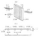
図1に基本的な構成を説明図として示す。
符号1は「無機材料による透明な基体」を示す。基体1の平坦な面1Aの側に「導電性材料による1次元ライン格子」が埋め込まれている。
符号2i−1、2i、2i+1、2i+2、・・は、1次元ライン格子として埋め込まれた導電性材料による各「格子線」の横断面を示している。
【0010】
格子線2i等は、図面に直交する方向へ長く伸び、図面の左右方向に1次元格子状に配列して「1次元ライン格子」を構成している。また、埋め込まれた状態の各格子線の露呈部と基体1の平坦な面1Aとは同一の平面をなす。
【0011】
なお、1次元ライン格子が「無機材料による透明な基体の平坦な面に埋め込まれる」とは、無機偏光素子の構造上の特徴を謂うものであり、無機偏光素子の製造過程において、予め形成された1次元ライン格子が「基体表面に機械的に埋め込まれる」訳ではない。
【0012】
請求項1記載の無機偏光素子は、上記構造において、以下の特徴を有する。 即ち、無機材料による透明な基体1の屈折率:n、導電性材料による1次元ライン格子の各格子線2iの配列ピッチ:d、光の波長:λが、条件:
(1) 0<n・d/λ<0.7
を満足する。
【0013】
即ち、一般に、偏光化作用を及ぼすべき光の波長が短くなるほど、屈折率:nとピッチ:dの積が小さくなるようにして、条件(1)を満足させればよい。
【0014】
後述するように、1次元ライン格子の各格子線の横断面形状は図1に示す「矩形形状」以外にも種々の形状が可能であるが、図1に示すように「矩形形状」を横断面形状とする場合は、上記パラメータ:n・d/λの値を0.1とし、「矩形形状」における幅:a、厚さ:t、屈折率:n、配列ピッチ:d、波長:λが、条件:
(2) 0<a<d
(3) 0<t<0.22λ/n
を満足することが好ましい(請求項2)。
【0015】
請求項1記載の無機偏光素子において、導電性材料による1次元ライン格子における各格子線の横断面形状は、上記矩形形状の他にも「台形形状、楔形状、半円形状もしくは半楕円形状」であることができる(請求項3)。
【0016】
請求項1または2または3記載の無機偏光素子において、1次元ライン格子を構成する導電性材料は「金属」であることができる(請求項4)。導電性材料としては、金属以外に半導体材料も使用可能である。上記金属は、アルミニウム、銀、金もしくはクロムの何れかであることができる(請求項5)。
【0017】
無機偏光素子を「可視域の光に対し、非透過光を反射する偏光素子」として用いる場合には、1次元ライン格子を、可視光に対して高い反射率を持つ「アルミニウムもしくは銀」で形成することが好ましく(請求項6)、逆に「可視域の光に対し、非透過光を反射させない偏光素子」として用いる場合には、可視光を吸収しやすい「クロム」で形成することが好ましい(請求項7)。また、無機偏光素子を「近赤外領域の光に対し、非透過光を反射する偏光素子」として用いる場合には、1次元ライン格子を「金」で形成することが好ましい(請求項8)。
【0018】
請求項1〜8の任意の1に記載の無機偏光素子は「無機材料による基体を平行平板とする」ことにより偏光板として実施できる(請求項9)。
この発明の偏光光学素子は「偏光機能と他の光学機能を兼備」した偏光光学素子である。
請求項10記載の偏光光学素子は、請求項1〜8の任意の1に記載の無機偏光素子における無機材料による基体の「1次元ライン格子が形成されない部分」に、反射面および/または屈折面を形成し、「1次元ライン格子と協働する光学作用」を持たせたものである。
【0019】
例えば、無機材料による基体を「直角プリズム」として形成し、その斜面以外の2面のうち、一方の面に1次元ライン格子を埋め込んで偏光素子面とし、他方の面にレンズ面(屈折面)を形成し、斜面には反射面を形成する。このようにすると、例えば、自然偏光の光を偏光素子面から入射させ、直線偏光化された光を反射面で反射させ、この反射光をレンズ面の作用で発散させたり集束させたりすることができる。
【0020】
請求項10記載の偏光光学素子は「無機材料による基体の、1次元ライン格子が形成された面に対向する側の面にレンズ面が形成された」構成とすることができる(請求項11)。この場合、さらに、1次元ライン格子が埋め込まれた平坦な面に「片面が平面であるレンズ」を接合一体化できる(請求項12)。この請求項12記載の偏光光学素子では、導電性材料による1次元ライン格子が「2つのレンズ面により挟まれた形態」となる。
【0021】
上記請求項10記載の偏光光学素子はまた「無機材料による基体の、1次元ライン格子が形成された面に対向する側の面にマイクロレンズアレイが形成された構成」とすることもできる(請求項13)。
【0022】
請求項14記載の液晶素子は「透過光の偏光方向を電気的に制御できる液晶素子に対して、請求項9記載の無機偏光素子を1対、偏光子および検光子として組合せて」なる液晶素子である。このようにして「液晶スイッチング素子」を実現できる。また、液晶素子がアレイ配列されたものである場合には、液晶パネルとして構成できる。
【0023】
請求項15記載の液晶素子は「素子ごとに透過光の偏光方向を電気的に制御できる液晶素子アレイに対して、請求項13記載の偏光光学素子を1対、偏光子及び検光子として組合せ、且つ、偏光光学素子におけるマイクロレンズのアレイ配列を液晶素子アレイのアレイ配列と合致させた」ことを特徴とする。マイクロレンズアレイの各マイクロレンズにより、液晶素子アレイの液晶素子に光を集光させることにより液晶パネルにおける光利用効率を高めることができる。
【0024】
なお、導電性材料による1次元ライン格子が埋め込まれる基体を構成する無機材料は、石英ガラスや通常の各種光学ガラスを好適に用いることができるが、これに限らず、無機材料で使用波長に対して透明なものを適宜に利用できる。
【0025】
【発明の実施の形態】
以下、実施の形態を説明する。
図2は、請求項9記載の無機偏光素子の実施の1形態を説明するための図である。図2(a)に示すように、無機偏光素子10は「平行平板状」であり、無機材料による平行平板状の基体10Aの片面側に、導電性材料による1次元ライン格子10Bが埋め込まれて形成されている。基板10Aとしては光学ガラス、1次元ライン格子10Bの導電性材料としては金属を想定している。
【0026】
図2(a)に示すように、無機偏光素子10の一方の側から入射光LIを入射させると、1次元ライン格子10Bにおける格子線の長手方向(図の上下方向)に電場振動面を持つ成分(以下「垂直偏光」という)は、反射光LRとなって反射され、1次元ライン格子10Bの格子配列方向に電場振動面を持つ成分(以下「水平偏光」という)は、透過光LTとなって透過する。このようにして、直線偏光状態の光を透過光LT、反射光LRとして得ることができる。
【0027】
図2(b)は、図2(a)の部分横断面を示している。符号10Bi−1、10Bi、10Bi+1、・・は、1次元ライン格子10Bを構成する「導電性材料による格子線」を示し、各格子線10Biは、図2(b)の図面に直交する方向へ直線状に伸び、図の左右方向へ互いに平行に配列して「1次元ライン格子」をなしている。
【0028】
埋め込まれた1次元ライン格子10Bの露呈部(図の上側の面)と基体10Aの平坦な面が同一の平面をなす。なお、この形態例において、基体10の両側の面には「反射防止膜」がコーティングされている。
【0029】
各格子線10Biの横断面形状は、幅:a、厚さ:tの矩形形状である。図の如く、1次元ライン格子における格子線10Biの配列ピッチをdとし、幅:aとピッチ:dの関係を、a=d/π(πは円周率)とする。また、基体10Aを構成する無機材料の屈折率を「n」とし、入射光LIの波長を「λ」とする。
【0030】
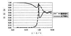
このとき、n・d/λを無次元のパラメータとして変化させ、無機偏光素子10に、垂直偏光と水平偏光を入射させたときの、各々の偏光に対する透過率の変化を「電磁場解析」により調べた結果、図3に示す如くになった。
図3の縦軸は透過率、横軸(対数目盛)はパラメータ:n・d/λである。
【0031】
この図から明らかなように、パラメータ:n・d/λが0.1以下では、水平偏光は略完全に遮断され、垂直偏光は略完全に透過する。また、パラメータ:n・d/λが0.7以下では、水平偏光の透過率は20%、垂直偏光の透過率は80%である。
【0032】
したがって、無機偏光素子10が実用上「偏光素子」として使用できるパラメータ:n・d/λの範囲は、条件:
(1) 0<n・d/λ<0.7
の範囲であることが分かる。特に、パラメータ:n・d/λが0.1以下では、良好な消光比を実現でき、偏向素子として極めて良好である。
【0033】
即ち、図2に示す無機偏光素子10は、無機材料による透明な基体10Aの平坦な面に、導電性材料による1次元ライン格子10Bが埋め込まれ、埋め込まれた1次元ライン格子10Bの露呈部と基体10Aの平坦な面が同一の平面をなすように形成され、無機材料による透明な基体の屈折率:n、導電性材料による1次元ライン格子の各格子線の配列ピッチ:d、光の波長:λが、条件(1)を満足する(請求項1)。
【0034】
次ぎに、図2の実施の形態において、パラメータ:n・d/λ=0.1(即ち、d=0.1λ/n)とし、この条件下において、格子線の幅:aと配列ピッチ:dの比:a/dを変化させたときの、水平・垂直偏光の透過率の変化を図4に示し、このときの消光比(水平偏光の透過率/垂直偏光の透過率)の変化を図5に示す。図5の縦軸が消光比を表す。
【0035】
図4から明らかなように、a/dが大きくなると、垂直偏光の透過率は急激に減少するのに対し、水平偏光の透過率はa/d=0.2程度までは略100%の透過率を持ち、それ以後は次第に減少する傾向をもつ。一方、消光比は、図5に示すように、a/dの増大とともに図の如く漸増し、a/dが略0.7程度のところで極大を持つ。
【0036】
即ち、格子線の幅:aは、ピッチ:dとの関係では、
(1) 0<a<d
の範囲で許容されるが、aが0に近づくほど、垂直偏光の透過率も高くなるため入射光を直線偏光化する「偏光化効率」は悪くなる。また、aが大きくなると、水平偏光の透過率は急激に減少するが、aがdに近づくに連れて水平偏光の透過率も漸減する。これは、格子線間の間隔が小さくなって、透明な領域が狭まることによる。このため、aがdに近づくと偏光化効率は高くなるが、偏光素子としては「暗い」ものになる。
【0037】
一方、消光比の方は、aがdに近づくに連れて急激に増加する。この点を考えると、a/dのより好ましい範囲は、偏光化効率および明るさの面から
0.1<a/d<0.8
であり、さらに、偏光化効率・明るさとともに消光比を考慮すると、
0.2<a/d<0.8
がさらに好ましい範囲となる。
【0038】
次ぎに、n・d/λ=0.1の条件下において、格子線10Biにおける幅:aと厚さ:tの割合:t/aを変化させたときの、水平・垂直偏光の透過率の変化を図6に、消光比の変化を図7に示す。図7の縦軸が消光比である。
【0039】
図6から明らかなように、垂直偏光の透過率はt/aに殆ど依存しないが、水平偏光の透過率はt/aの増大と伴に漸減する傾向がある。また、消光比は、図7から明らかなように、t/aの増大と伴に増大して飽和することが分かる。
【0040】
図7に示すように、消光比(縦軸)は「t/aが略7以上では飽和する」ので、厚さ:tを7aより厚くしても消光比を変化させることはできない。
従って、「消光比として、所望の値を設定できる厚さ:t」の範囲は、t<7aと考えられる。
【0041】
図7の消光比特性が得られる条件は、前述の如く、n・d/λ=0.1であり、また、a=d/πであるからd=πa、n・d/λ=n・πa/λ=0.1であるから、a=0.1λ/(π・n)となり、これから上記範囲「t<7a」は、
t<7・0.1λ/(π・n)=(0.7/3.14)λ/n=0.22λ/n
となり、結局、条件:
(3) 0<t<0.22λ/n
を満足することにより、消光比を、1:10〜1:108の範囲で「所望の値」に設定することが可能となる。(請求項2)。
【0042】
逆に、t≧7aの場合には消光比が飽和しており、この領域では消光比の変化がないので、この領域では「飽和した消光比に対して、水平偏光の透過率を適宜に調整可能」である。
【0043】
上には、無機偏光素子における「1次元ライン格子を構成する各格子線の横断面形状」を矩形形状としたが、格子線の横断面形状は他にも種々のものが可能である。
【0044】
図8(a)に示す例では、格子線21i等の横断面形状が「逆台形形状」であり、(b)に示す例では、格子線22i等の横断面形状は「楔形状」、(c)に示す例では、格子線23i等の横断面形状は「半楕円形状」である(請求項3)。
【0045】
図3に示すような各種の横断面形状を持つ1次元ライン格子の場合にも、前述の条件(1)が有効であることは勿論である。また、上記各種の横断面形状の場合についても、条件(3)に相当する「消光比として、所望の値を設定できる厚さ:t」の範囲を設定可能である。この場合、厚さ:tは、図3に示す各横断面形状における「溝の深さ」に(横断面形状に応じた)係数を乗じたものとなる。格子線の横断面形状は、上記以外にも「半円形状」等、種々の形状が許容される。
【0046】
ここで、この発明の無機偏光素子の「無機材料による透明な基体の平坦な面に、導電性材料による1次元ライン格子が埋め込まれ、埋め込まれた1次元ライン格子の露呈部と基体の平坦な面が同一の平面をなす」構造を実現する方法を簡単に説明する。このような構造を実現する方法には種々のものが可能である。
【0047】
例えば、無機材料として光学ガラスを想定すると、この光学ガラスの平坦な面にフォトレジスト層を形成し、このフォトレジスト層に電子線描画やX線描画の手法で「1次元ライン格子に相当するパターン」を書き込み、現像により「格子線となるべき部分のフォトレジスト」を除去する。
【0048】
次いで、現像後のフォトレジスト層をマスクとしてエッチングを行い、フォトレジストに形成された「1次元ライン格子に相当するパターン」を、光学ガラスの平坦な面に転写し、光学ガラス表面に「1次元ライン格子に対応する溝パターン」を形成する。
【0049】
この状態で金属材料、例えば、アルミニウムをCVD(chemical vapor deposit)等の化学蒸着法や物理蒸着を用いた成膜法、あるいは鍍金等の堆積法で、フォトレジスト層表面および「1次元ライン格子に対応する溝パターン」に層状に付着させる。
【0050】
その後、「アルミニウムの付着したフォトレジスト層」を、光学ガラスの平坦な面から除去すると、1次元ライン格子に相当するアルミニウム細線の配列が得られるので、光学ガラスの表面側をブラスト処理して「光学ガラス面から盛り上がっているアルミニウム部分」を除去し、埋め込まれた「アルミニウムによる1次元ライン格子の露呈部」と基体の平坦な面が同一の平面をなすようにする。
【0051】
別の方法として、光学ガラスの平坦な面に電子線描画等により直接的に「1次元ライン格子に対応する溝パターン」を加工し、物理蒸着やCVD等の化学蒸着により上記平坦な面全体にアルミニウムを付着させるとともに、溝パターンにアルミニウムを充填する。その後、電子スパッタリング等で「平坦な面上のアルミニウム」を除去し、溝部に充填されたアルミニウムのみを残せば、所望の1次元ライン格子が得られる。
【0052】
上記アルミニウムに代えて、銀、金、クロム等を、無機偏光素子の使用目的に応じて用い得ることは前述した通りである(請求項6、7、8)。勿論、別の導電性材料を使用することもできる。
【0053】
先に、図2以下に即して実施の形態を説明した無機偏光素子10は、無機材料による基体10Aを平行平板としたものであり(請求項9)であり、「偏光板」として使用可能であった。
【0054】
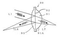
図9に示すのは、請求項10、11、12記載の偏光光学素子の実施の1形態を示している。
この偏光光学素子90では、無機材料による基体91の、1次元ライン格子92が形成されない部分に、屈折面91Aが形成され、1次元ライン格子92と協働する光学作用を持つ(請求項10)。
【0055】
そして、無機材料による基体91の、1次元ライン格子92が形成された面に対向する面に形成された屈折面92は「凸レンズ面」であり(請求項11)、1次元ライン格子92の形成された面の側には、片面が平面である凸レンズ93を接合一体化されている(請求項12)。
【0056】
このような偏光光学素子90では、例えば、凸レンズ93の側から水平・垂直偏光成分を含む入射光LIを平行光束として入射させると、水平偏光成分は透過光LTとなり、レンズ93とレンズ面91Aの作用で集束光束となり、垂直偏光成分は反射光LRとなり、レンズ93の作用により集束光束となる。
【0057】
レンズ面91Aを凹レンズ面とすることも、レンズ93を凹レンズとすることもでき、例えば「透過光LTを発散光、反射光LRを集束光とする」ことも「透過光LTを集束光、反射光LRを発散光とする」ことも「透過光LT、反射光LRともに発散光とする」ことも可能である。
【0058】
図10は、請求項14、15記載の液晶素子の実施の1形態を説明するための図である。
符号101、102は偏光光学素子、符号103は液晶素子アレイをそれぞれ示している。液晶素子アレイは、単位画素を構成する液晶素子LCijを2次元正方行列状にアレイ配列したものであって、図示されない駆動回路により各液晶素子LCijに独立に駆動電圧を印加できるようになっている。
【0059】
各液晶素子LCijは「ツイステッドネマチック液晶」による素子であり、駆動電圧が印加されていない状態で「直線偏光状態の光」を入射させると、入射光の偏光面を90度旋回させて透過させる。駆動電圧を印加すると、入射光の偏光面の向きを保ったまま透過させる。
【0060】
偏光光学素子101、102は無機材料を基体として構成され、その片面に導電性材料による1次元ライン格子が埋め込まれ、埋め込まれた1次元ライン格子の露呈部と基体の平坦な面が同一の平面をなすように形成されている。
【0061】
偏光光学素子101では、埋め込み形成された1次元ライン格子101Aは、格子線の配列方向が図面の上下方向を向き、偏光光学素子102では、埋め込み形成された1次元ライン格子102Aは、格子線の配列方向が図面に直交する方向になっている。従って、偏光光学素子101と102とでは、1次元ライン格子101A、102Aは格子配列方向が互いに直交している。
【0062】
このため、偏光光学素子101、102を1対の偏光素子として、偏光子・検光子として使用できる。
【0063】
また、偏光光学素子101の1次元ライン格子101Aが形成されたのと逆側の面には、マイクロレンズML1ijが、液晶素子LCijの配列に1:1で対応して形成されており、偏光光学素子102の1次元ライン格子102Aが形成されたのと逆側の面には、マイクロレンズML2ijが、液晶素子LCijの配列に1:1で対応して形成されている。
【0064】
従って、例えば、図10の左方から自然偏光の光を入射させると、偏光子としての偏光光学素子101の作用により、入射した光のうち「図の上下方向に振動する偏光成分」のみが透過光となり、各マイクロレンズML1ijにより、各マイクロレンズに対応する液晶素子LCijに集光する。この光は液晶素子LCijを透過するが、その際、駆動電圧が印加されていない液晶素子では偏光面が90度旋回され、マイクロレンズML2ijにより集束されて1次元ライン格子102Aを透過する。
【0065】
また、駆動電圧が印加された液晶素子では偏光面の旋回が起こらず、マイクロレンズML2ijにより集束された透過光は、1次元ライン格子102Aにより遮断される。このように、偏光光学素子102から図の右方へ射出する光は、駆動電圧の印加された液晶素子LCijに従って空間的に強度変調される。
【0066】
このように強度変調された光を適宜の結像光学系で結像させれば、2次元画像を表示することができる。
【0067】
従来、液晶パネルに偏光子・検光子として「有機偏光素子」が用いられているが、有機偏光素子は、熱の影響による経年変化で性能の劣化が生じることが知られている。図10に示すように、この発明の無機偏光素子を偏光子・検光子として用いれば、耐熱性や機械的強度が極めて高いので、耐久性のある液晶パネルを実現できる。
【0068】
即ち、図10に示す偏光光学素子101、102は、無機材料による基体の、1次元ライン格子101A、102Aが形成された面に対向する面に、マイクロレンズアレイが形成された偏光光学素子(請求項13)であり、また、透過光の偏光方向を電気的に制御できる液晶素子103に対し、偏光子及び検光子として組合せられ(請求項14)、素子ごとに透過光の偏光方向を電気的に制御できる液晶素子アレイ103に対して偏光子及び検光子として組合せられ、且つ、偏光光学素子101、102におけるマイクロレンズのアレイ配列が液晶素子アレイ103のアレイ配列と合致している(請求項15)。
【0069】
【実施例】
図10に示した偏光光学素子101、102を、以下の如くに作成した。使用波長:λを可視領域:400〜700nmとし、基体となるべき無機材料として屈折率:1.4の平行平板状の光学ガラスを用い、その片面に、液晶素子アレイにおける素子配列に対応した凸のマイクロレンズのアレイを形成したものを基体とした。
【0070】
1次元ライン格子を構成する導電性材料としてアルミニウムを用い、格子線の配列ピッチ:dを85・7nmとし、前記パラメータ:n・d/λ<0.3とした。即ち、λ=400nmに対して、n・d<12.0nmである。
【0071】
格子線の横断面を矩形形状とし、その幅:a=30nm、厚さ:t=100nmとした。
【0072】
作製は、前述した「光学ガラスの平坦な面にフォトレジスト層を形成し、このフォトレジスト層に電子線描画で1次元ライン格子に相当するパターンを書き込み、現像後、エッチングを行い、光学ガラス表面に1次元ライン格子に対応する溝パターンを形成し、アルミニウムをCVDにより層状に付着させ、その後、アルミニウムの付着したフォトレジスト層を光学ガラスの平坦な面から除去し、光学ガラスの表面側をブラスト処理し、埋め込まれたアルミニウムの1次元ライン格子の露呈部と基体の平坦な面が同一の平面をなすようにする方法」によった。
【0073】
このようにして得られた偏光光学素子101、102における、水平偏光、垂直偏光の透過率は図11に示す如くであり、消光比は図12に示す如くである。図11から明らかなように、可視領域:400〜700nmの波長範囲において、透過率は、垂直偏光につき実質的に0、水平偏光につき80%以上である。また、可視領域内で消光比は1:100以上である。
【0074】
即ち、この偏光光学素子は良好な偏光子・検光子として使用可能である。
【0075】
【発明の効果】
以上のようにこの発明によれば、新規な無機偏光素子および偏光光学素子および液晶素子を実現できる。この発明の無機偏光素子は、上記の如く、無機材料による透明な基体の平坦な面に、導電性材料による1次元ライン格子が埋め込まれ、埋め込まれた1次元ライン格子の露呈部と基体の平坦な面が同一の平面をなす構造となっているので、1次元ライン格子と無機材料による基体との結合が堅固であって機械的な耐久性に優れ、材料が無機材料と導電性材料であるので耐熱性にも優れている。また、条件(1)を満足することにより良好な偏光化機能を有する。
【0076】
従って、この発明の無機偏光素子を用いる偏光光学素子・液晶素子は、偏光化機能に優れ、また、熱の影響を問題としないですむ。
【図面の簡単な説明】
【図1】この発明の無機偏光素子の構造を説明するための図である。
【図2】この発明の無機偏光素子の実施の1形態を説明するための図である。
【図3】条件(1)を説明するための図である。
【図4】条件(2)、(3)を説明するための図である。
【図5】条件(2)、(3)を説明するための図である。
【図6】条件(2)、(3)を説明するための図である。
【図7】条件(2)、(3)を説明するための図である。
【図8】1次元ライン格子の格子線の横断面形状を3例示す図である。
【図9】請求項12記載の偏光光学素子の実施の1形態を説明するための図である。
【図10】請求項15記載の液晶素子の実施の1形態を説明するための図である。
【図11】実施例の光学特性を説明するための図である。
【図12】実施例の光学特性を説明するための図である。
【符号の説明】
1 無機材料による基体
1A 基体1の平坦な面
2i 基体1の平坦な面1Aに埋め込まれた導電性材料による1次元ライン格子の格子線[0001]
TECHNICAL FIELD OF THE INVENTION
The present invention relates to an inorganic polarizing element, a polarizing optical element, and a liquid crystal element.
[0002]
[Prior art]
A polarizing element is an optical element that transmits light linearly polarized in a specific direction, and is widely used in various optical devices. Although tourmaline is widely known as a polarizing element, it is expensive and is not suitable for being incorporated as a component in an optical device. As a polarizing element which has good mass productivity and can be manufactured at low cost, a "wire grid type polarizing element" in which a one-dimensional line grating is formed on a transparent substrate with a thin line made of a conductive material has been proposed (see
[0003]
The wire grid type polarizing element utilizes the fact that "there is no electric field in the conductor". That is, when natural polarized light is incident on such a polarizing element, the vibration component of the vibration electric field in the longitudinal direction of the grid line in the one-dimensional line grid becomes zero in the grid line. The linearly polarized light oscillating in the direction is transmitted.
[0004]
Since the one-dimensional line gratings described in
[0005]
[0006]
[Patent Document 1]
JP-A-10-153706
[Patent Document 2]
US Pat. No. 6,122,103
[Patent Document 3]
U.S. Pat. No. 6,288,840 B1
[0007]
[Problems to be solved by the invention]
An object of the present invention is to realize a novel inorganic polarizing element which is a wire grid type polarizing element and has a simple structure and excellent heat resistance and mechanical strength. Another object of the present invention is to realize a polarizing optical element and a liquid crystal element using the inorganic polarizing element.
[0008]
[Means for Solving the Problems]
The inorganic polarizing element according to the present invention is configured such that a one-dimensional line grating made of a conductive material is embedded in a flat surface of a transparent base made of an inorganic material, and the exposed part of the embedded one-dimensional line grating is the same as the flat surface of the base. Is formed so as to form a flat surface of "."
[0009]
FIG. 1 shows a basic configuration as an explanatory diagram.
Sign 2i-1, 2i, 2i + 1, 2i + 2,... Indicate the cross-section of each "grid line" of conductive material embedded as a one-dimensional line grid.
[0010]
The grid lines 2i and the like extend long in a direction perpendicular to the drawing, and are arranged in a one-dimensional grid in the left-right direction of the drawing to form a “one-dimensional line grid”. The exposed portion of each grid line in the embedded state and the flat surface 1A of the
[0011]
The expression that the one-dimensional line grating is “embedded on the flat surface of a transparent substrate made of an inorganic material” is a so-called structural feature of the inorganic polarizing element, and is formed in advance in the manufacturing process of the inorganic polarizing element. This does not mean that the one-dimensional line grating is "mechanically embedded in the substrate surface".
[0012]
The inorganic polarizing element according to
(1) 0 <nd · λ <0.7
To be satisfied.
[0013]
That is, in general, the condition (1) may be satisfied so that the product of the refractive index: n and the pitch: d becomes smaller as the wavelength of the light to be polarized becomes shorter.
[0014]
As will be described later, the cross-sectional shape of each grid line of the one-dimensional line grid can be various shapes other than the “rectangular shape” shown in FIG. 1, but crosses the “rectangular shape” as shown in FIG. In the case of a planar shape, the value of the above parameter: n · d / λ is set to 0.1, and the width of the “rectangular shape”: a, thickness: t, refractive index: n, array pitch: d, wavelength: λ But the condition:
(2) 0 <a <d
(3) 0 <t <0.22λ / n
Is preferably satisfied (claim 2).
[0015]
2. The inorganic polarizing element according to
[0016]
In the inorganic polarizing element according to
[0017]
When using an inorganic polarizing element as a "polarizing element that reflects non-transmitted light with respect to visible light," a one-dimensional line grating is formed of "aluminum or silver" which has a high reflectance for visible light On the contrary, in the case of using as a “polarizing element that does not reflect non-transmitted light with respect to light in the visible region”, it is preferable to form it with “chromium” which easily absorbs visible light. (Claim 7). When the inorganic polarizing element is used as a “polarizing element that reflects non-transmitted light with respect to light in the near infrared region”, it is preferable that the one-dimensional line grating is formed of “gold”. .
[0018]
The inorganic polarizing element according to any one of
The polarizing optical element of the present invention is a polarizing optical element that “has both a polarizing function and another optical function”.
According to a tenth aspect of the present invention, there is provided the polarizing optical element according to any one of the first to eighth aspects, wherein a reflection surface and / or a refraction surface is provided on the “portion where the one-dimensional line grating is not formed” of the inorganic material in the inorganic polarization element. And has an “optical action cooperating with the one-dimensional line grating”.
[0019]
For example, a substrate made of an inorganic material is formed as a “right-angle prism”, and one of two surfaces other than the inclined surface is embedded with a one-dimensional line grating to be a polarizing element surface, and the other surface is a lens surface (refractive surface). Is formed, and a reflection surface is formed on the slope. In this case, for example, light of naturally polarized light can be made incident from the polarizing element surface, linearly polarized light can be reflected by the reflecting surface, and the reflected light can be diverged or focused by the action of the lens surface. it can.
[0020]
The polarizing optical element according to claim 10 may have a configuration in which "a lens surface is formed on a surface of the base made of an inorganic material, which is opposite to a surface on which the one-dimensional line grating is formed" (claim 11). . In this case, it is possible to join and integrate a “one-sided flat lens” with a flat surface in which the one-dimensional line grating is embedded (claim 12). In the polarization optical element according to the twelfth aspect, the one-dimensional line grating made of a conductive material has a “form sandwiched between two lens surfaces”.
[0021]
The polarizing optical element according to the tenth aspect can also have a configuration in which a microlens array is formed on a surface of the base made of an inorganic material opposite to the surface on which the one-dimensional line grating is formed. Item 13).
[0022]
A liquid crystal element according to claim 14 is a liquid crystal element comprising “a liquid crystal element capable of electrically controlling the polarization direction of transmitted light, and a combination of the inorganic polarization element according to
[0023]
The liquid crystal element according to claim 15 is “a liquid crystal element array capable of electrically controlling the polarization direction of transmitted light for each element, and the polarization optical element according to claim 13 is combined as a pair, a polarizer and an analyzer, In addition, the array arrangement of the microlenses in the polarizing optical element is matched with the array arrangement of the liquid crystal element array. " The light utilization efficiency in the liquid crystal panel can be increased by condensing light on the liquid crystal elements of the liquid crystal element array by each micro lens of the micro lens array.
[0024]
In addition, as the inorganic material constituting the substrate in which the one-dimensional line grating made of a conductive material is embedded, quartz glass or various kinds of ordinary optical glass can be preferably used, but not limited thereto, and the inorganic material may be used for the wavelength used. Transparent material can be used as appropriate.
[0025]
BEST MODE FOR CARRYING OUT THE INVENTION
Hereinafter, embodiments will be described.
FIG. 2 is a view for explaining an embodiment of the inorganic polarizing element according to
[0026]
As shown in FIG. 2A, when the incident light LI is incident from one side of the inorganic
[0027]
FIG. 2B shows a partial cross section of FIG. 2A.
[0028]
The exposed portion (upper surface in the figure) of the embedded one-dimensional line grating 10B and the flat surface of the base 10A form the same plane. In this embodiment, both sides of the base 10 are coated with an “anti-reflection film”.
[0029]
Each
[0030]
At this time, by changing nd / λ as a dimensionless parameter, a change in transmittance for each polarized light when the vertically polarized light and the horizontally polarized light are incident on the inorganic
The vertical axis in FIG. 3 is the transmittance, and the horizontal axis (log scale) is the parameter: n · d / λ.
[0031]
As is clear from this figure, when the parameter: nd / λ is 0.1 or less, horizontal polarized light is almost completely cut off, and vertical polarized light is almost completely transmitted. When the parameter: nd / λ is 0.7 or less, the transmittance of the horizontally polarized light is 20%, and the transmittance of the vertically polarized light is 80%.
[0032]
Therefore, the parameter in which the inorganic
(1) 0 <nd · λ <0.7
It turns out that it is the range of. In particular, when the parameter: nd / λ is 0.1 or less, a good extinction ratio can be realized, and the deflecting element is extremely good.
[0033]
That is, the inorganic
[0034]
Next, in the embodiment of FIG. 2, the parameter: n · d / λ = 0.1 (that is, d = 0.1λ / n). Under this condition, the width of the grid line: a and the arrangement pitch: FIG. 4 shows the change in the transmittance of the horizontal and vertical polarized light when the ratio of d: a / d is changed, and the change in the extinction ratio (transmittance of the horizontal polarized light / transmittance of the vertical polarized light) at this time. As shown in FIG. The vertical axis in FIG. 5 represents the extinction ratio.
[0035]
As is clear from FIG. 4, as a / d increases, the transmittance of vertically polarized light rapidly decreases, while the transmittance of horizontally polarized light is approximately 100% until a / d = about 0.2. Rate, after which it tends to decrease gradually. On the other hand, the extinction ratio gradually increases as shown in FIG. 5 as a / d increases, and has a maximum at a / d of about 0.7.
[0036]
That is, the width of the grid line: a is related to the pitch: d by:
(1) 0 <a <d
However, as “a” approaches 0, the transmittance of vertically polarized light also increases, so that the “polarization efficiency” for linearly polarizing incident light deteriorates. Also, when a becomes large, the transmittance of the horizontally polarized light decreases sharply, but as a approaches d, the transmittance of the horizontally polarized light also gradually decreases. This is because the space between the grid lines is reduced and the transparent area is reduced. For this reason, the polarization efficiency increases as a approaches d, but the polarization element becomes “dark”.
[0037]
On the other hand, the extinction ratio sharply increases as a approaches d. Considering this point, a more preferable range of a / d is determined in terms of polarization efficiency and brightness.
0.1 <a / d <0.8
In addition, considering the extinction ratio together with the polarization efficiency and brightness,
0.2 <a / d <0.8
Is a more preferable range.
[0038]
Next, under the condition of n · d / λ = 0.1, the
[0039]
As is clear from FIG. 6, the transmittance of vertically polarized light hardly depends on t / a, but the transmittance of horizontally polarized light tends to gradually decrease with increasing t / a. In addition, as is apparent from FIG. 7, the extinction ratio increases and saturates as t / a increases.
[0040]
As shown in FIG. 7, since the extinction ratio (vertical axis) is "saturated when t / a is approximately 7 or more", the extinction ratio cannot be changed even if the thickness: t is greater than 7a.
Therefore, the range of “thickness at which a desired value can be set as the extinction ratio: t” is considered to be t <7a.
[0041]
The conditions for obtaining the extinction ratio characteristics in FIG. 7 are nd / λ = 0.1 as described above, and since a = d / π, d = πa and nd / λ = n · Since πa / λ = 0.1, a = 0.1λ / (π · n). From this, the range “t <7a” becomes
t <7 · 0.1λ / (π · n) = (0.7 / 3.14) λ / n = 0.22λ / n
And, after all, the conditions:
(3) 0 <t <0.22λ / n
To satisfy the following condition, the extinction ratio is increased from 1:10 to 1:10.8Can be set to a “desired value” within the range. (Claim 2).
[0042]
Conversely, when t ≧ 7a, the extinction ratio is saturated, and there is no change in the extinction ratio in this region. Therefore, in this region, “the transmittance of the horizontal polarized light is appropriately adjusted with respect to the saturated extinction ratio. Is possible. "
[0043]
Although the “cross-sectional shape of each grid line forming the one-dimensional line grid” in the inorganic polarizing element is rectangular, the cross-sectional shape of the grid line may be various.
[0044]
In the example shown in FIG.iEtc. are “inverted trapezoidal shapes”, and in the example shown in FIG.iIs a wedge shape, and in the example shown in FIG.iIs a "semi-elliptical shape" (claim 3).
[0045]
It goes without saying that the above-mentioned condition (1) is also effective in the case of a one-dimensional line grating having various cross-sectional shapes as shown in FIG. Also, in the case of the above various cross-sectional shapes, a range of “thickness: t at which a desired value can be set as the extinction ratio” corresponding to the condition (3) can be set. In this case, the thickness: t is obtained by multiplying the “groove depth” in each cross-sectional shape shown in FIG. 3 by a coefficient (according to the cross-sectional shape). Various cross-sectional shapes other than the above, such as a “semicircular shape”, are allowed as the cross-sectional shape of the grid lines.
[0046]
Here, the one-dimensional line grating made of a conductive material is embedded on the flat surface of the transparent base made of an inorganic material, and the exposed part of the embedded one-dimensional line grating and the flat surface of the base are made of the inorganic polarizing element of the present invention. A method of realizing a structure in which “surfaces form the same plane” will be briefly described. Various methods are possible for realizing such a structure.
[0047]
For example, assuming an optical glass as an inorganic material, a photoresist layer is formed on a flat surface of the optical glass, and a pattern corresponding to a one-dimensional line lattice is formed on the photoresist layer by an electron beam drawing or X-ray drawing technique. Is written, and the “photoresist in a portion to be a grid line” is removed by development.
[0048]
Next, etching is performed using the developed photoresist layer as a mask, and the “pattern corresponding to the one-dimensional line lattice” formed on the photoresist is transferred to a flat surface of the optical glass, and “one-dimensionally” is formed on the optical glass surface. A groove pattern corresponding to the line grating is formed.
[0049]
In this state, a metal material, for example, aluminum is applied to the photoresist layer surface and the “one-dimensional line grid” by a chemical vapor deposition method such as CVD (chemical vapor deposition), a film formation method using physical vapor deposition, or a deposition method such as plating. It is deposited in layers on the "corresponding groove pattern".
[0050]
After that, when the “photoresist layer with aluminum” is removed from the flat surface of the optical glass, an array of aluminum fine wires corresponding to a one-dimensional line lattice is obtained. The “aluminum portion raised from the optical glass surface” is removed so that the embedded “exposed portion of the one-dimensional line grating made of aluminum” and the flat surface of the substrate are flush with each other.
[0051]
As another method, a “groove pattern corresponding to a one-dimensional line grid” is directly formed on a flat surface of an optical glass by electron beam drawing or the like, and the entire flat surface is formed by physical vapor deposition or chemical vapor deposition such as CVD. Aluminum is deposited and the groove pattern is filled with aluminum. Thereafter, by removing the “aluminum on the flat surface” by electron sputtering or the like and leaving only the aluminum filled in the groove, a desired one-dimensional line grating can be obtained.
[0052]
As described above, silver, gold, chromium, and the like can be used in place of aluminum in accordance with the purpose of use of the inorganic polarizing element (claims 6, 7, and 8). Of course, another conductive material can be used.
[0053]
The inorganic
[0054]
FIG. 9 shows an embodiment of the polarizing optical element according to
In the polarization
[0055]
The
[0056]
In such a polarization
[0057]
The lens surface 91A may be a concave lens surface, or the
[0058]
FIG. 10 is a view for explaining one embodiment of the liquid crystal element according to the fourteenth and fifteenth aspects.
[0059]
Each liquid crystal element LCijIs a device made of “twisted nematic liquid crystal”, and when “light in a linearly polarized state” is made incident with no drive voltage applied, the incident light is rotated by 90 degrees and transmitted. When a driving voltage is applied, incident light is transmitted while maintaining the direction of the polarization plane.
[0060]
The polarizing
[0061]
In the polarization
[0062]
For this reason, the polarizing
[0063]
The microlens ML1 is provided on the surface of the polarizing
[0064]
Therefore, for example, when naturally polarized light is incident from the left side of FIG. 10, only the “polarized component that vibrates vertically” in the incident light is transmitted by the action of the polarization
[0065]
Further, in the liquid crystal element to which the driving voltage is applied, the rotation of the polarization plane does not occur, and the micro lens ML2ijThe transmitted light converged by the light is blocked by the one-dimensional line grating 102A. As described above, the light emitted from the polarizing
[0066]
A two-dimensional image can be displayed by forming an image of the intensity-modulated light with an appropriate imaging optical system.
[0067]
Conventionally, an “organic polarizing element” is used as a polarizer / analyzer in a liquid crystal panel, but it is known that the performance of the organic polarizing element deteriorates due to aging due to the influence of heat. As shown in FIG. 10, when the inorganic polarizing element of the present invention is used as a polarizer / analyzer, heat resistance and mechanical strength are extremely high, so that a durable liquid crystal panel can be realized.
[0068]
That is, the polarizing
[0069]
【Example】
The polarization
[0070]
Aluminum was used as the conductive material constituting the one-dimensional line lattice, the arrangement pitch of the lattice lines: d was 85.7 nm, and the parameter was nd / λ <0.3. That is, for λ = 400 nm, nd <12.0 nm.
[0071]
The cross section of the grid line was rectangular, and its width: a = 30 nm and thickness: t = 100 nm.
[0072]
The fabrication was performed by forming a photoresist layer on the flat surface of the optical glass described above, writing a pattern corresponding to a one-dimensional line grid on the photoresist layer by electron beam drawing, developing, etching, and etching the optical glass surface. Then, a groove pattern corresponding to the one-dimensional line grating is formed, aluminum is deposited in a layer by CVD, the photoresist layer with aluminum is removed from the flat surface of the optical glass, and the surface side of the optical glass is blasted. The method is such that the exposed portion of the processed and embedded aluminum one-dimensional line grid and the flat surface of the substrate are coplanar.
[0073]
The transmittances of the horizontally polarized light and the vertically polarized light in the polarizing
[0074]
That is, this polarizing optical element can be used as a good polarizer and analyzer.
[0075]
【The invention's effect】
As described above, according to the present invention, a novel inorganic polarizing element, a polarizing optical element, and a liquid crystal element can be realized. As described above, according to the inorganic polarizing element of the present invention, the one-dimensional line grating made of a conductive material is embedded in the flat surface of the transparent base made of an inorganic material, and the exposed part of the embedded one-dimensional line grating and the flat surface of the base are made flat. The structure is such that the one-dimensional line grid and the base made of an inorganic material are firmly bonded and have excellent mechanical durability, and the materials are an inorganic material and a conductive material. It is also excellent in heat resistance. Further, by satisfying the condition (1), a good polarization function is provided.
[0076]
Therefore, the polarizing optical element / liquid crystal element using the inorganic polarizing element of the present invention is excellent in the polarizing function and does not have to be affected by heat.
[Brief description of the drawings]
FIG. 1 is a view for explaining a structure of an inorganic polarizing element of the present invention.
FIG. 2 is a view for explaining an embodiment of the inorganic polarizing element of the present invention.
FIG. 3 is a diagram for explaining a condition (1).
FIG. 4 is a diagram for explaining conditions (2) and (3).
FIG. 5 is a diagram for explaining conditions (2) and (3).
FIG. 6 is a diagram for explaining conditions (2) and (3).
FIG. 7 is a diagram for explaining conditions (2) and (3).
FIG. 8 is a diagram showing three examples of cross-sectional shapes of grid lines of a one-dimensional line grid.
FIG. 9 is a view for explaining an embodiment of the polarizing optical element according to claim 12;
FIG. 10 is a view for explaining one embodiment of the liquid crystal element according to claim 15;
FIG. 11 is a diagram for explaining optical characteristics of an example.
FIG. 12 is a diagram for explaining optical characteristics of an example.
[Explanation of symbols]
1 Substrate made of inorganic material
1A Flat surface of
2i Grid line of one-dimensional line grid made of conductive material embedded in flat surface 1A of
Claims (15)
Translated fromJapanese無機材料による透明な基体の屈折率:n、導電性材料による1次元ライン格子の各格子線の配列ピッチ:d、光の波長:λが、条件:
(1) 0<n・d/λ<0.7
を満足することを特徴とする無機偏光素子。A one-dimensional line grating made of a conductive material is embedded in a flat surface of a transparent base made of an inorganic material, and an exposed portion of the embedded one-dimensional line grating and a flat surface of the base are made to be on the same plane. Formed,
The refractive index of a transparent substrate made of an inorganic material: n, the arrangement pitch of each grid line of a one-dimensional line grating made of a conductive material: d, the wavelength of light: λ,
(1) 0 <nd · λ <0.7
An inorganic polarizing element characterized by satisfying the following.
導電性材料による1次元ライン格子における各格子線の横断面形状が矩形形状であり、無機材料による透明な基体の屈折率:n、導電性材料による1次元ライン格子の各格子線の配列ピッチ:d、光の波長:λによるパラメータ:n・d/λの値が0.1であり、且つ、上記各格子線の横断面形状の矩形形状における幅:a、厚さ:t、上記屈折率:n、配列ピッチ:d、波長:λが、条件:
(2) 0<a<d
(3) 0<t<0.22λ/n
を満足することを特徴とする無機偏光素子。The inorganic polarizing element according to claim 1,
The cross-sectional shape of each grid line in the one-dimensional line grid made of a conductive material is rectangular, and the refractive index of a transparent substrate made of an inorganic material: n, the arrangement pitch of each grid line of the one-dimensional line grid made of a conductive material: d, the parameter of the wavelength of light: λ: the value of n · d / λ is 0.1, and the width in the rectangular cross-sectional shape of each lattice line is a: the thickness: t, the refractive index is : N, array pitch: d, wavelength: λ, condition:
(2) 0 <a <d
(3) 0 <t <0.22λ / n
An inorganic polarizing element characterized by satisfying the following.
導電性材料による1次元ライン格子における、各格子線の横断面形状が、台形形状、楔形状、半円形状もしくは半楕円形状であることを特徴とする無機偏光素子。The inorganic polarizing element according to claim 1,
An inorganic polarizing element, wherein a cross-sectional shape of each grid line in a one-dimensional line grid made of a conductive material is trapezoidal, wedge-shaped, semicircular, or semi-elliptical.
1次元ライン格子を構成する導電性材料が金属であることを特徴とする無機偏光素子。The inorganic polarizing element according to claim 1, 2 or 3,
An inorganic polarizing element, wherein the conductive material constituting the one-dimensional line grating is a metal.
1次元ライン格子を構成する金属が、アルミニウム、銀、金、クロムの何れかであることを特徴とする無機偏光素子。The inorganic polarizing element according to claim 4,
An inorganic polarizing element, wherein the metal constituting the one-dimensional line grating is any of aluminum, silver, gold, and chromium.
可視域の光に対し、非透過光を反射する偏光素子として用いられ、1次元ライン格子がアルミニウムもしくは銀で形成されることを特徴とする無機偏光素子。The inorganic polarizing element according to claim 5,
An inorganic polarizing element, which is used as a polarizing element that reflects non-transmitted light with respect to light in the visible region, wherein the one-dimensional line grating is formed of aluminum or silver.
可視域の光に対し、非透過光を反射させない偏光素子として用いられ、1次元ライン格子がクロムで形成されることを特徴とする無機偏光素子。The inorganic polarizing element according to claim 5,
An inorganic polarizing element, which is used as a polarizing element that does not reflect non-transmitted light with respect to light in the visible region, and in which a one-dimensional line grating is formed of chromium.
近赤外領域の光に対し、非透過光を反射する偏光素子として用いられ、1次元ライン格子が金で形成されることを特徴とする無機偏光素子。The inorganic polarizing element according to claim 5,
An inorganic polarizing element, which is used as a polarizing element that reflects non-transmitted light with respect to light in the near-infrared region and has a one-dimensional line grating formed of gold.
無機材料による基体の、1次元ライン格子が形成された面に対向する側の面に、レンズ面が形成されたことを特徴とする偏光光学素子。The polarizing optical element according to claim 10,
A polarizing optical element, wherein a lens surface is formed on a surface of a base made of an inorganic material opposite to a surface on which a one-dimensional line grating is formed.
無機材料による基体の、1次元ライン格子が埋め込まれた平坦な面に対向する側の面に、マイクロレンズアレイが形成されたことを特徴とする偏光光学素子。The polarizing optical element according to claim 10,
A polarizing optical element, wherein a microlens array is formed on a surface of a base made of an inorganic material opposite to a flat surface in which a one-dimensional line grating is embedded.
Priority Applications (1)
| Application Number | Priority Date | Filing Date | Title |
|---|---|---|---|
| JP2002319918AJP4376507B2 (en) | 2002-11-01 | 2002-11-01 | Polarizing optical element |
Applications Claiming Priority (1)
| Application Number | Priority Date | Filing Date | Title |
|---|---|---|---|
| JP2002319918AJP4376507B2 (en) | 2002-11-01 | 2002-11-01 | Polarizing optical element |
Publications (2)
| Publication Number | Publication Date |
|---|---|
| JP2004157159Atrue JP2004157159A (en) | 2004-06-03 |
| JP4376507B2 JP4376507B2 (en) | 2009-12-02 |
Family
ID=32801002
Family Applications (1)
| Application Number | Title | Priority Date | Filing Date |
|---|---|---|---|
| JP2002319918AExpired - LifetimeJP4376507B2 (en) | 2002-11-01 | 2002-11-01 | Polarizing optical element |
Country Status (1)
| Country | Link |
|---|---|
| JP (1) | JP4376507B2 (en) |
Cited By (32)
| Publication number | Priority date | Publication date | Assignee | Title |
|---|---|---|---|---|
| JP2006023621A (en)* | 2004-07-09 | 2006-01-26 | Konica Minolta Holdings Inc | Optical element and molding method thereof |
| JP2006058615A (en)* | 2004-08-20 | 2006-03-02 | Sumitomo Chemical Co Ltd | Polarization separation element with embedded metal wires |
| JP2006091309A (en)* | 2004-09-22 | 2006-04-06 | Ricoh Opt Ind Co Ltd | Etch back method, method for manufacturing inorganic polarizer by using this method, etching stop control device for realizing these methods, and inorganic polarizer to be manufactured |
| WO2006038575A1 (en)* | 2004-10-07 | 2006-04-13 | Sharp Kabushiki Kaisha | Transparent electrode and liquid crystal display device provided with the same |
| JP2006154382A (en)* | 2004-11-30 | 2006-06-15 | Sumitomo Chemical Co Ltd | Color filter having polarization separation function and display device including the same |
| KR100642003B1 (en)* | 2005-06-02 | 2006-11-02 | 엘지전자 주식회사 | Wire grid polarizer, its manufacturing method and backlight unit having the same |
| JP2007046938A (en)* | 2005-08-08 | 2007-02-22 | Mitsutoyo Corp | Interferometer |
| JP2007101921A (en)* | 2005-10-05 | 2007-04-19 | Seiko Epson Corp | Liquid crystal device and projection display device |
| JP2008139730A (en)* | 2006-12-05 | 2008-06-19 | Nippon Oil Corp | Wire grid polarizer and method for manufacturing the same, and retardation film and liquid crystal display device using the same |
| US7630133B2 (en) | 2004-12-06 | 2009-12-08 | Moxtek, Inc. | Inorganic, dielectric, grid polarizer and non-zero order diffraction grating |
| US7630132B2 (en) | 2005-05-23 | 2009-12-08 | Ricoh Company, Ltd. | Polarization control device |
| US7692860B2 (en) | 2006-12-07 | 2010-04-06 | Cheil Industries, Inc. | Wire grid polarizer and method of manufacturing the same |
| US7789515B2 (en) | 2007-05-17 | 2010-09-07 | Moxtek, Inc. | Projection device with a folded optical path and wire-grid polarizer |
| US7800823B2 (en) | 2004-12-06 | 2010-09-21 | Moxtek, Inc. | Polarization device to polarize and further control light |
| US7813039B2 (en) | 2004-12-06 | 2010-10-12 | Moxtek, Inc. | Multilayer wire-grid polarizer with off-set wire-grid and dielectric grid |
| JP2010266483A (en)* | 2009-05-12 | 2010-11-25 | Oji Paper Co Ltd | Manufacturing method of metal fine wire sheet having uneven shape, and metal thin wire sheet having uneven shape |
| US7961393B2 (en) | 2004-12-06 | 2011-06-14 | Moxtek, Inc. | Selectively absorptive wire-grid polarizer |
| JP4838804B2 (en)* | 2004-09-23 | 2011-12-14 | ローム アンド ハース デンマーク ファイナンス エーエス | Wire grid polarizer with low fill factor |
| JP2012073484A (en)* | 2010-09-29 | 2012-04-12 | Asahi Glass Co Ltd | Wire grid type polarizer and liquid crystal display device |
| JP2012118237A (en)* | 2010-11-30 | 2012-06-21 | Asahi Kasei E-Materials Corp | Wire grid polarization plate for infrared ray |
| US8248696B2 (en) | 2009-06-25 | 2012-08-21 | Moxtek, Inc. | Nano fractal diffuser |
| KR101185057B1 (en)* | 2006-03-31 | 2012-09-21 | 엘지이노텍 주식회사 | Nono pattern structure, multilayer optical sheet having the nono pattern structure and backlight unit |
| US8611007B2 (en) | 2010-09-21 | 2013-12-17 | Moxtek, Inc. | Fine pitch wire grid polarizer |
| US8755113B2 (en) | 2006-08-31 | 2014-06-17 | Moxtek, Inc. | Durable, inorganic, absorptive, ultra-violet, grid polarizer |
| US8873144B2 (en) | 2011-05-17 | 2014-10-28 | Moxtek, Inc. | Wire grid polarizer with multiple functionality sections |
| US8913321B2 (en) | 2010-09-21 | 2014-12-16 | Moxtek, Inc. | Fine pitch grid polarizer |
| US8913320B2 (en) | 2011-05-17 | 2014-12-16 | Moxtek, Inc. | Wire grid polarizer with bordered sections |
| US8922890B2 (en) | 2012-03-21 | 2014-12-30 | Moxtek, Inc. | Polarizer edge rib modification |
| US9348076B2 (en) | 2013-10-24 | 2016-05-24 | Moxtek, Inc. | Polarizer with variable inter-wire distance |
| JP2016148871A (en)* | 2016-05-09 | 2016-08-18 | 旭化成株式会社 | Wire grid polarization plate for infrared ray, image sensor for infrared ray, and camera for infrared ray |
| US9423646B2 (en) | 2013-04-18 | 2016-08-23 | Samsung Display Co., Ltd. | Display device |
| JP2024177077A (en)* | 2023-06-08 | 2024-12-19 | ツー-シックス デラウェア インコーポレイテッド | Fabrication of polarizers, diffraction gratings, and metasurfaces by ion implantation |
- 2002
- 2002-11-01JPJP2002319918Apatent/JP4376507B2/ennot_activeExpired - Lifetime
Cited By (38)
| Publication number | Priority date | Publication date | Assignee | Title |
|---|---|---|---|---|
| JP2006023621A (en)* | 2004-07-09 | 2006-01-26 | Konica Minolta Holdings Inc | Optical element and molding method thereof |
| JP2006058615A (en)* | 2004-08-20 | 2006-03-02 | Sumitomo Chemical Co Ltd | Polarization separation element with embedded metal wires |
| JP2006091309A (en)* | 2004-09-22 | 2006-04-06 | Ricoh Opt Ind Co Ltd | Etch back method, method for manufacturing inorganic polarizer by using this method, etching stop control device for realizing these methods, and inorganic polarizer to be manufactured |
| JP4838804B2 (en)* | 2004-09-23 | 2011-12-14 | ローム アンド ハース デンマーク ファイナンス エーエス | Wire grid polarizer with low fill factor |
| JPWO2006038575A1 (en)* | 2004-10-07 | 2008-07-31 | シャープ株式会社 | Transparent electrode and liquid crystal display device including the same |
| WO2006038575A1 (en)* | 2004-10-07 | 2006-04-13 | Sharp Kabushiki Kaisha | Transparent electrode and liquid crystal display device provided with the same |
| JP2006154382A (en)* | 2004-11-30 | 2006-06-15 | Sumitomo Chemical Co Ltd | Color filter having polarization separation function and display device including the same |
| US8027087B2 (en) | 2004-12-06 | 2011-09-27 | Moxtek, Inc. | Multilayer wire-grid polarizer with off-set wire-grid and dielectric grid |
| US7961393B2 (en) | 2004-12-06 | 2011-06-14 | Moxtek, Inc. | Selectively absorptive wire-grid polarizer |
| US7813039B2 (en) | 2004-12-06 | 2010-10-12 | Moxtek, Inc. | Multilayer wire-grid polarizer with off-set wire-grid and dielectric grid |
| US7630133B2 (en) | 2004-12-06 | 2009-12-08 | Moxtek, Inc. | Inorganic, dielectric, grid polarizer and non-zero order diffraction grating |
| US7800823B2 (en) | 2004-12-06 | 2010-09-21 | Moxtek, Inc. | Polarization device to polarize and further control light |
| US7630132B2 (en) | 2005-05-23 | 2009-12-08 | Ricoh Company, Ltd. | Polarization control device |
| KR100642003B1 (en)* | 2005-06-02 | 2006-11-02 | 엘지전자 주식회사 | Wire grid polarizer, its manufacturing method and backlight unit having the same |
| JP2007046938A (en)* | 2005-08-08 | 2007-02-22 | Mitsutoyo Corp | Interferometer |
| JP2007101921A (en)* | 2005-10-05 | 2007-04-19 | Seiko Epson Corp | Liquid crystal device and projection display device |
| KR101185057B1 (en)* | 2006-03-31 | 2012-09-21 | 엘지이노텍 주식회사 | Nono pattern structure, multilayer optical sheet having the nono pattern structure and backlight unit |
| US8947772B2 (en) | 2006-08-31 | 2015-02-03 | Moxtek, Inc. | Durable, inorganic, absorptive, ultra-violet, grid polarizer |
| US8755113B2 (en) | 2006-08-31 | 2014-06-17 | Moxtek, Inc. | Durable, inorganic, absorptive, ultra-violet, grid polarizer |
| JP2008139730A (en)* | 2006-12-05 | 2008-06-19 | Nippon Oil Corp | Wire grid polarizer and method for manufacturing the same, and retardation film and liquid crystal display device using the same |
| US7692860B2 (en) | 2006-12-07 | 2010-04-06 | Cheil Industries, Inc. | Wire grid polarizer and method of manufacturing the same |
| US7789515B2 (en) | 2007-05-17 | 2010-09-07 | Moxtek, Inc. | Projection device with a folded optical path and wire-grid polarizer |
| JP2010266483A (en)* | 2009-05-12 | 2010-11-25 | Oji Paper Co Ltd | Manufacturing method of metal fine wire sheet having uneven shape, and metal thin wire sheet having uneven shape |
| US8248696B2 (en) | 2009-06-25 | 2012-08-21 | Moxtek, Inc. | Nano fractal diffuser |
| US8913321B2 (en) | 2010-09-21 | 2014-12-16 | Moxtek, Inc. | Fine pitch grid polarizer |
| US9523805B2 (en) | 2010-09-21 | 2016-12-20 | Moxtek, Inc. | Fine pitch wire grid polarizer |
| US8611007B2 (en) | 2010-09-21 | 2013-12-17 | Moxtek, Inc. | Fine pitch wire grid polarizer |
| JP2012073484A (en)* | 2010-09-29 | 2012-04-12 | Asahi Glass Co Ltd | Wire grid type polarizer and liquid crystal display device |
| JP2012118237A (en)* | 2010-11-30 | 2012-06-21 | Asahi Kasei E-Materials Corp | Wire grid polarization plate for infrared ray |
| US8913320B2 (en) | 2011-05-17 | 2014-12-16 | Moxtek, Inc. | Wire grid polarizer with bordered sections |
| US8873144B2 (en) | 2011-05-17 | 2014-10-28 | Moxtek, Inc. | Wire grid polarizer with multiple functionality sections |
| US8922890B2 (en) | 2012-03-21 | 2014-12-30 | Moxtek, Inc. | Polarizer edge rib modification |
| US9423646B2 (en) | 2013-04-18 | 2016-08-23 | Samsung Display Co., Ltd. | Display device |
| US9348076B2 (en) | 2013-10-24 | 2016-05-24 | Moxtek, Inc. | Polarizer with variable inter-wire distance |
| US9354374B2 (en) | 2013-10-24 | 2016-05-31 | Moxtek, Inc. | Polarizer with wire pair over rib |
| US9632223B2 (en) | 2013-10-24 | 2017-04-25 | Moxtek, Inc. | Wire grid polarizer with side region |
| JP2016148871A (en)* | 2016-05-09 | 2016-08-18 | 旭化成株式会社 | Wire grid polarization plate for infrared ray, image sensor for infrared ray, and camera for infrared ray |
| JP2024177077A (en)* | 2023-06-08 | 2024-12-19 | ツー-シックス デラウェア インコーポレイテッド | Fabrication of polarizers, diffraction gratings, and metasurfaces by ion implantation |
Also Published As
| Publication number | Publication date |
|---|---|
| JP4376507B2 (en) | 2009-12-02 |
Similar Documents
| Publication | Publication Date | Title |
|---|---|---|
| JP2004157159A (en) | Inorganic polarizing element, polarizing optical element, and liquid crystal element | |
| CN112088141B (en) | Diffraction grating for beam redirection | |
| JP2004309903A (en) | Inorganic polarizing element, polarizing optical element, and liquid crystal element | |
| KR100744863B1 (en) | Insertion Wire Grating Polarizer for Visible Light Band | |
| JP5271404B2 (en) | Light emitting device | |
| CN107219685B (en) | Display device and display method of display device | |
| JP5294280B2 (en) | Polarized semiconductor light emitting device | |
| CN103038677B (en) | Sheet and light emitting device | |
| US20080138013A1 (en) | High Efficiency Optical Diffraction Device | |
| KR20070065337A (en) | Low Fill Factor Wire Grid Polarizer | |
| JP2007273275A (en) | Organic EL light emitting device | |
| KR20090089671A (en) | Nano wire grid polarizer and its manufacturing method | |
| CN109946882B (en) | Backlight source, preparation method thereof and backlight module | |
| JP5571641B2 (en) | Liquid crystal display | |
| JP2010085990A (en) | Wire grid polarizing plate | |
| WO2002025325A1 (en) | Polarizing function element, optical isolator, laser diode module and method of producing polarizing function element | |
| KR970022396A (en) | Deflection element and projection display device using the same | |
| JP2001059963A (en) | Liquid crystal display device | |
| JPH11237507A (en) | Polarizer and method for producing the same | |
| US7206121B2 (en) | Optical path switching device | |
| WO2019182158A1 (en) | Light beam switching element, assembly of same, and control method for same | |
| KR100701092B1 (en) | Manufacturing method of liquid crystal display device | |
| CN109597238B (en) | Optical film layer and display device | |
| TW200428103A (en) | Electroluminescence device, manufacturing method thereof, and liquid crystal display device using the electroluminescence device | |
| JP4574252B2 (en) | Three-dimensional periodic structure, optical element, and optical product |
Legal Events
| Date | Code | Title | Description |
|---|---|---|---|
| A621 | Written request for application examination | Free format text:JAPANESE INTERMEDIATE CODE: A621 Effective date:20051027 | |
| A977 | Report on retrieval | Free format text:JAPANESE INTERMEDIATE CODE: A971007 Effective date:20090116 | |
| A131 | Notification of reasons for refusal | Free format text:JAPANESE INTERMEDIATE CODE: A131 Effective date:20090203 | |
| A521 | Written amendment | Free format text:JAPANESE INTERMEDIATE CODE: A523 Effective date:20090327 | |
| TRDD | Decision of grant or rejection written | ||
| A01 | Written decision to grant a patent or to grant a registration (utility model) | Free format text:JAPANESE INTERMEDIATE CODE: A01 Effective date:20090908 | |
| A01 | Written decision to grant a patent or to grant a registration (utility model) | Free format text:JAPANESE INTERMEDIATE CODE: A01 | |
| A61 | First payment of annual fees (during grant procedure) | Free format text:JAPANESE INTERMEDIATE CODE: A61 Effective date:20090909 | |
| R150 | Certificate of patent (=grant) or registration of utility model | Free format text:JAPANESE INTERMEDIATE CODE: R150 | |
| FPAY | Renewal fee payment (prs date is renewal date of database) | Free format text:PAYMENT UNTIL: 20120918 Year of fee payment:3 |