JP2004154583A - Medical treatment implant for respirator tract condition - Google Patents
Medical treatment implant for respirator tract conditionDownload PDFInfo
- Publication number
- JP2004154583A JP2004154583AJP2003403694AJP2003403694AJP2004154583AJP 2004154583 AJP2004154583 AJP 2004154583AJP 2003403694 AJP2003403694 AJP 2003403694AJP 2003403694 AJP2003403694 AJP 2003403694AJP 2004154583 AJP2004154583 AJP 2004154583A
- Authority
- JP
- Japan
- Prior art keywords
- implant
- needle
- fibers
- component
- soft palate
- Prior art date
- Legal status (The legal status is an assumption and is not a legal conclusion. Google has not performed a legal analysis and makes no representation as to the accuracy of the status listed.)
- Granted
Links
- 239000007943implantSubstances0.000titleclaimsabstractdescription184
- 238000011282treatmentMethods0.000titledescription12
- 239000000835fiberSubstances0.000claimsabstractdescription60
- 239000000463materialSubstances0.000claimsabstractdescription36
- 230000004044responseEffects0.000claimsabstractdescription32
- 238000006243chemical reactionMethods0.000claimsabstractdescription8
- 239000000560biocompatible materialSubstances0.000claimsabstractdescription5
- 239000007787solidSubstances0.000claimsabstractdescription5
- 230000015572biosynthetic processEffects0.000claimsdescription18
- 238000001356surgical procedureMethods0.000claimsdescription16
- 238000002513implantationMethods0.000claimsdescription15
- 230000008859changeEffects0.000claimsdescription9
- 239000012530fluidSubstances0.000claimsdescription9
- 229920000728polyesterPolymers0.000claimsdescription9
- 239000000411inducerSubstances0.000claimsdescription7
- 239000007788liquidSubstances0.000claimsdescription5
- 230000012010growthEffects0.000claimsdescription3
- 230000001939inductive effectEffects0.000claimsdescription3
- 230000001737promoting effectEffects0.000claimsdescription3
- 229910001285shape-memory alloyInorganic materials0.000claimsdescription3
- 239000000126substanceSubstances0.000claimsdescription3
- 239000003795chemical substances by applicationSubstances0.000claimsdescription2
- 230000007423decreaseEffects0.000claimsdescription2
- 230000003176fibrotic effectEffects0.000claimsdescription2
- 238000010438heat treatmentMethods0.000claimsdescription2
- 238000005452bendingMethods0.000claims2
- 206010016654FibrosisDiseases0.000claims1
- 230000003352fibrogenic effectEffects0.000claims1
- 230000004761fibrosisEffects0.000claims1
- 210000002345respiratory systemAnatomy0.000claims1
- 230000003313weakening effectEffects0.000claims1
- 210000001584soft palateAnatomy0.000abstractdescription125
- 206010041235SnoringDiseases0.000abstractdescription31
- 238000003780insertionMethods0.000description18
- 230000037431insertionEffects0.000description18
- 238000000034methodMethods0.000description15
- 210000001519tissueAnatomy0.000description12
- 239000011162core materialSubstances0.000description9
- 230000000694effectsEffects0.000description8
- 210000001983hard palateAnatomy0.000description8
- 208000027418Wounds and injuryDiseases0.000description7
- 201000000615hard palate cancerDiseases0.000description7
- 210000004872soft tissueAnatomy0.000description7
- 206010052428WoundDiseases0.000description6
- 230000004048modificationEffects0.000description5
- 238000012986modificationMethods0.000description5
- RTAQQCXQSZGOHL-UHFFFAOYSA-NTitaniumChemical compound[Ti]RTAQQCXQSZGOHL-UHFFFAOYSA-N0.000description4
- 230000008901benefitEffects0.000description4
- 230000000670limiting effectEffects0.000description4
- 229910001000nickel titaniumInorganic materials0.000description4
- 208000001797obstructive sleep apneaDiseases0.000description4
- 239000005022packaging materialSubstances0.000description4
- 210000003320palatal muscleAnatomy0.000description4
- 230000000638stimulationEffects0.000description4
- 239000003356suture materialSubstances0.000description4
- 230000009747swallowingEffects0.000description4
- 210000003437tracheaAnatomy0.000description4
- 239000003242anti bacterial agentSubstances0.000description3
- 230000006870functionEffects0.000description3
- 210000003205muscleAnatomy0.000description3
- 210000001989nasopharynxAnatomy0.000description3
- HLXZNVUGXRDIFK-UHFFFAOYSA-Nnickel titaniumChemical compound[Ti].[Ti].[Ti].[Ti].[Ti].[Ti].[Ti].[Ti].[Ti].[Ti].[Ti].[Ni].[Ni].[Ni].[Ni].[Ni].[Ni].[Ni].[Ni].[Ni].[Ni].[Ni].[Ni].[Ni].[Ni]HLXZNVUGXRDIFK-UHFFFAOYSA-N0.000description3
- 210000003254palateAnatomy0.000description3
- 229920000642polymerPolymers0.000description3
- 230000002980postoperative effectEffects0.000description3
- 230000029058respiratory gaseous exchangeEffects0.000description3
- 230000008467tissue growthEffects0.000description3
- 229910052719titaniumInorganic materials0.000description3
- 239000010936titaniumSubstances0.000description3
- 229920004934Dacron®Polymers0.000description2
- LFQSCWFLJHTTHZ-UHFFFAOYSA-NEthanolChemical compoundCCOLFQSCWFLJHTTHZ-UHFFFAOYSA-N0.000description2
- 230000001133accelerationEffects0.000description2
- 230000009471actionEffects0.000description2
- 230000002411adverseEffects0.000description2
- 229940088710antibiotic agentDrugs0.000description2
- 230000003115biocidal effectEffects0.000description2
- 210000000988bone and boneAnatomy0.000description2
- 239000011248coating agentSubstances0.000description2
- 238000000576coating methodMethods0.000description2
- 230000006378damageEffects0.000description2
- 238000009826distributionMethods0.000description2
- 235000013305foodNutrition0.000description2
- 238000002595magnetic resonance imagingMethods0.000description2
- 230000008569processEffects0.000description2
- 230000002035prolonged effectEffects0.000description2
- 238000007634remodelingMethods0.000description2
- 238000007493shaping processMethods0.000description2
- 201000002859sleep apneaDiseases0.000description2
- 230000007480spreadingEffects0.000description2
- 238000003892spreadingMethods0.000description2
- 230000001954sterilising effectEffects0.000description2
- 238000004659sterilization and disinfectionMethods0.000description2
- 229920002994synthetic fiberPolymers0.000description2
- 102000008186CollagenHuman genes0.000description1
- 108010035532CollagenProteins0.000description1
- CEAZRRDELHUEMR-URQXQFDESA-NGentamicinChemical compoundO1[C@H](C(C)NC)CC[C@@H](N)[C@H]1O[C@H]1[C@H](O)[C@@H](O[C@@H]2[C@@H]([C@@H](NC)[C@@](C)(O)CO2)O)[C@H](N)C[C@@H]1NCEAZRRDELHUEMR-URQXQFDESA-N0.000description1
- 229930182566GentamicinNatural products0.000description1
- 239000004743PolypropyleneSubstances0.000description1
- HZEWFHLRYVTOIW-UHFFFAOYSA-N[Ti].[Ni]Chemical compound[Ti].[Ni]HZEWFHLRYVTOIW-UHFFFAOYSA-N0.000description1
- 239000000853adhesiveSubstances0.000description1
- 230000001070adhesive effectEffects0.000description1
- 229910045601alloyInorganic materials0.000description1
- 239000000956alloySubstances0.000description1
- 235000013361beverageNutrition0.000description1
- 210000001124body fluidAnatomy0.000description1
- 238000009954braidingMethods0.000description1
- 210000000845cartilageAnatomy0.000description1
- 239000000919ceramicSubstances0.000description1
- 229920001436collagenPolymers0.000description1
- 238000007796conventional methodMethods0.000description1
- 238000012937correctionMethods0.000description1
- 238000005520cutting processMethods0.000description1
- 238000013016dampingMethods0.000description1
- 230000007547defectEffects0.000description1
- 238000013461designMethods0.000description1
- 238000010586diagramMethods0.000description1
- 238000002224dissectionMethods0.000description1
- 230000009429distressEffects0.000description1
- 230000035622drinkingEffects0.000description1
- 230000008030eliminationEffects0.000description1
- 238000003379elimination reactionMethods0.000description1
- 210000002409epiglottisAnatomy0.000description1
- 210000003238esophagusAnatomy0.000description1
- 235000019441ethanolNutrition0.000description1
- 238000011156evaluationMethods0.000description1
- 238000002594fluoroscopyMethods0.000description1
- 229960002518gentamicinDrugs0.000description1
- 230000005484gravityEffects0.000description1
- 230000002650habitual effectEffects0.000description1
- 230000035876healingEffects0.000description1
- 230000036541healthEffects0.000description1
- 210000003823hyoid boneAnatomy0.000description1
- 238000002347injectionMethods0.000description1
- 239000007924injectionSubstances0.000description1
- 208000014674injuryDiseases0.000description1
- 230000010354integrationEffects0.000description1
- 230000002427irreversible effectEffects0.000description1
- 239000002085irritantSubstances0.000description1
- 231100000021irritantToxicity0.000description1
- 230000007794irritationEffects0.000description1
- 238000003698laser cuttingMethods0.000description1
- 239000003550markerSubstances0.000description1
- 239000002184metalSubstances0.000description1
- 229910052751metalInorganic materials0.000description1
- 239000007769metal materialSubstances0.000description1
- 230000000116mitigating effectEffects0.000description1
- 210000004400mucous membraneAnatomy0.000description1
- 239000005445natural materialSubstances0.000description1
- 230000000422nocturnal effectEffects0.000description1
- 238000002559palpationMethods0.000description1
- 230000036961partial effectEffects0.000description1
- 229920002463poly(p-dioxanone) polymerPolymers0.000description1
- 229920000052poly(p-xylylene)Polymers0.000description1
- 239000000622polydioxanoneSubstances0.000description1
- -1polypropylenePolymers0.000description1
- 229920001155polypropylenePolymers0.000description1
- 229920001343polytetrafluoroethylenePolymers0.000description1
- 239000004810polytetrafluoroethyleneSubstances0.000description1
- 235000015277porkNutrition0.000description1
- 230000002285radioactive effectEffects0.000description1
- 230000002829reductive effectEffects0.000description1
- 230000002441reversible effectEffects0.000description1
- 238000012552reviewMethods0.000description1
- 238000007789sealingMethods0.000description1
- 238000004904shorteningMethods0.000description1
- 229920002379silicone rubberPolymers0.000description1
- 239000004945silicone rubberSubstances0.000description1
- 208000019116sleep diseaseDiseases0.000description1
- 239000000243solutionSubstances0.000description1
- 230000035882stressEffects0.000description1
- 230000001225therapeutic effectEffects0.000description1
- 238000012800visualizationMethods0.000description1
- 238000007794visualization techniqueMethods0.000description1
Images


Classifications
- A—HUMAN NECESSITIES
- A61—MEDICAL OR VETERINARY SCIENCE; HYGIENE
- A61F—FILTERS IMPLANTABLE INTO BLOOD VESSELS; PROSTHESES; DEVICES PROVIDING PATENCY TO, OR PREVENTING COLLAPSING OF, TUBULAR STRUCTURES OF THE BODY, e.g. STENTS; ORTHOPAEDIC, NURSING OR CONTRACEPTIVE DEVICES; FOMENTATION; TREATMENT OR PROTECTION OF EYES OR EARS; BANDAGES, DRESSINGS OR ABSORBENT PADS; FIRST-AID KITS
- A61F5/00—Orthopaedic methods or devices for non-surgical treatment of bones or joints; Nursing devices ; Anti-rape devices
- A61F5/56—Devices for preventing snoring
- A61F5/566—Intra-oral devices
Landscapes
- Health & Medical Sciences (AREA)
- Vascular Medicine (AREA)
- Animal Behavior & Ethology (AREA)
- Nursing (AREA)
- Orthopedic Medicine & Surgery (AREA)
- Engineering & Computer Science (AREA)
- Biomedical Technology (AREA)
- Heart & Thoracic Surgery (AREA)
- Otolaryngology (AREA)
- Pulmonology (AREA)
- General Health & Medical Sciences (AREA)
- Life Sciences & Earth Sciences (AREA)
- Public Health (AREA)
- Veterinary Medicine (AREA)
- Orthopedics, Nursing, And Contraception (AREA)
- Prostheses (AREA)
- Surgical Instruments (AREA)
- Materials For Medical Uses (AREA)
Abstract
Description
Translated fromJapanese本発明はいびきを治療する方法および装置に関するものである。 The present invention relates to a method and apparatus for treating snoring.
関連出願に関するクロスリファレンス
本出願は2000年2月25日に出願された米国特許出願第09/513432号および第09/513039号の一部継続出願であり、これは両者とも共同発明者ティモシ・R・コンラッド(Timothy R.Conrad)、マーク・B・ナッドソン(Mark B.Knudson)およびジェリ・C・グリフィン(Jerry C.Griffin)の名前で1999年9月17日に出願された米国特許出願第09/398991号の一部継続出願である、1999年11月5日出願の米国特許出願第09/434653号の一部継続出願である。CROSS REFERENCE TO RELATED APPLICATIONS This application is a continuation-in-part of U.S. Patent Application Serial Nos. 09 / 513,432 and 09/513039, filed February 25, 2000, both of which are co-inventors Timothy R. U.S. patent application Ser. No. 09 / 434,653 filed on Nov. 5, 1999, which is a continuation-in-part application of US Pat.
いびきは科学的および学術的に高い注目を受けている。一つの刊行物は大人の人口の20%までがいびきを習慣としていると予想している。例えば、フアング(Huang)他の「いびきの生科学」エンデバ(Endeavour),96〜100ページ、第19巻、第3号(1995年)がある。いびきは夫婦の不和の深刻な原因となることがある。さらに、いびきは、いびきをかく人にとって深刻な健康の危機をもたらすことがある。習慣的にいびきをかく人の10%において、睡眠中の空気路のつぶれが閉塞性睡眠無呼吸症候群に結び付く。同上の刊行物。 Snoring has received high scientific and academic attention. One publication estimates that up to 20% of the adult population is habitually snoring. See, for example, Huang et al., "Bioscience of Snoring," Endeavor, pp. 96-100, Vol. 19, No. 3, 1995. Snoring can be a serious source of marital harm. In addition, snoring can pose a serious health crisis for snorers. In 10% of habitual snoreers, collapsed airways during sleep are associated with obstructive sleep apnea. Same as above.
いびきを対象とした幾多の努力にもかかわらず、いびきの効果的な治療法はなかった。従来のこのような治療は口ガードや、睡眠中にいびきをかく人が着用する別の器具を含んでいる。しかし、患者にはこのような器具が不快であり、使用をしばしば中断してしまう(夫婦間のストレスを増加させると思われる)。 Despite numerous efforts directed at snoring, there has been no effective treatment for snoring. Conventional such treatments include mouth guards and other devices worn by persons who snore while sleeping. However, patients are uncomfortable with such devices and often discontinue use (possibly increasing marital stress).
軟口蓋の電気刺激が、いびきや、閉塞性睡眠無呼吸の治療法として提案されている。例えば、シュワルツ(Schwartz)他の「いびきにおける軟口蓋に対する電気刺激の効果および閉塞性睡眠無呼吸」補綴歯科学会誌、273〜281ページ(1996年)参照。このような刺激を加えるデバイスは米国特許第5284161号および同第5792067号で説明されている。このようなデバイスは使用の摂生を患者が順守することならびに睡眠中の不具合を患者が受けることを必要とする器具である。睡眠無呼吸を治療する電気刺激はウィルファング(Wiltfang)他、「閉塞性睡眠無呼吸症候群における夜間下咽頭のつぶれを防ぐ上舌骨筋肉の昼間下顎電気刺激における第一結果」口腔および顎顔面外科の国際誌、21〜25ページ(1999年)で論じられている。 Electrical stimulation of the soft palate has been proposed as a treatment for snoring and obstructive sleep apnea. See, for example, Schwartz et al., "Effects of Electrical Stimulation on the Soft Palate in Snoring and Obstructive Sleep Apnea," Prosthodontic Society, pp. 273-281 (1996). Devices for applying such stimuli are described in U.S. Patent Nos. 5,284,161 and 5,792,067. Such devices are instruments that require the patient to adhere to a regimen of use and suffer from sleep problems. Electrical stimulation to treat sleep apnea is described by Wilfang et al., "First results in daytime mandibular electrical stimulation of superior hyoid bone muscle to prevent nocturnal hypopharyngeal collapse in obstructive sleep apnea syndrome" Oral and Maxillofacial Surgery International Journal, pages 21-25 (1999).
外科治療も以前より採用されている。このような治療の一つは咽喉形成である。この処置において、いわゆるレーザ切断が軟口蓋の後縁の約2cmを除去するのに使用され、これにより舌と喉の咽頭壁の間での軟口蓋の振動能力を減らす。この処置はいびきを和らげるのにしばしば効果的なものであるが、苦痛であり、望ましくない副作用をしばしばもたらす。すなわち、軟口蓋の後縁の除去は嚥下中や話している間に鼻の通路を密閉する軟口蓋の能力を含む。咽喉形成患者の予測される25%において、液体が飲用中に口から鼻へ逃出する。同書99ページにおいてファング他は述べている。咽喉形成(UPPP)についてはハリース(Harries)他「いびきの外科治療」、咽頭科学および耳科学誌、1105〜1106ページ(1996年)でも説明されており、これは軟口蓋の1.5cmまでの除去を説明している。いびき治療の評価についてはコール(Cole)他「いびき:検討と再評価」、耳鼻咽喉科誌、303〜306ページ(1995年)で論じられている。 Surgical treatment has also been employed for some time. One such treatment is throat formation. In this procedure, so-called laser cutting is used to remove about 2 cm of the posterior edge of the soft palate, thereby reducing the ability of the soft palate to vibrate between the tongue and the throat pharyngeal wall. While this treatment is often effective in relieving snoring, it is painful and often has undesirable side effects. That is, removal of the trailing edge of the soft palate involves the ability of the soft palate to seal the nasal passages during swallowing and speaking. In the expected 25% of throat shaping patients, liquid escapes from the mouth to the nose during drinking. On page 99 of the book, Fang et al. Throat formation (UPPP) is also described in Harries et al., “Surgical Treatment of Snoring”, Journal of Pharyngology and Otology, pp. 1105-1106 (1996), which removes the soft palate to 1.5 cm. Is explained. The evaluation of snoring treatment is discussed in Cole et al., "Snoring: Review and Reassessment," Otolaryngology, pp. 303-306 (1995).
同書でファング他は軟口蓋と、軟口蓋上の空気流に応答する揺動システムとしての口蓋いびきを論じている。結果として生じる軟口蓋(迅速に開閉する空気通路)の振動はいびきに関連した音を生じる動的応答である。ファング他は咽喉形成の別の方法も提案している。この提案は軟口蓋の表面に傷組織を形成するために外科レーザを使用することを含んでいる。傷は口蓋振動を減らすために軟口蓋の可撓性を減らすものである。ファング他はいびきを完全にあるいは略完全に減らし、且つ副作用を減らす最初の結果を報告している。 In that book, Fang et al. Discuss the soft palate and palate snoring as a rocking system that responds to airflow over the soft palate. The resulting vibration of the soft palate (air passage that opens and closes quickly) is a dynamic response that produces a sound associated with snoring. Fang et al. Have proposed alternative methods of throat formation. This proposal involves using a surgical laser to create wound tissue on the surface of the soft palate. Wounds reduce the flexibility of the soft palate to reduce palatal vibration. Fang et al. Report the first results to reduce snoring completely or almost completely and to reduce side effects.
咽喉形成やファング他が提案したものなどの外科処置は問題を有している。外科治療(すなわち、口蓋組織の除去や口蓋組織への傷付け)の面積は患者の状態を治療する必要以上のものである。外科レーザは高価である。提案された処置は長引いたり、不快な治癒期間があったりして苦痛である。処置は複雑であり、副作用や効能の違いをもたらす(例えば、ファング他は患者の75%に有望な結果を報告しており、患者の1/4全体が苦痛のある手術後に効果的に治療されないことを示唆している)。処置は永続する不具合を含んでいることもある。例えば、軟口蓋の傷組織は患者に継続した刺激をもたらすことがある。重要なのは、これらが起こった場合に、元に戻せないことであり、手術の利益により妥当化されない悪い副作用をもたらすことである。 Surgical procedures such as throat shaping and those proposed by Fang et al. Have problems. The area of surgical treatment (ie, removal of palatal tissue or injury to palatal tissue) is more than necessary to treat the patient's condition. Surgical lasers are expensive. The proposed treatment is painful with prolonged and unpleasant healing periods. The procedure is complex and results in side effects and differences in efficacy (e.g. Fang et al. Report promising results in 75% of patients, and one-quarter of patients are not effectively treated after painful surgery) Suggests that). The treatment may include a permanent defect. For example, soft palate wound tissue may cause continued irritation to the patient. Importantly, if these occur, they are irreversible and have adverse side effects that are not justified by the benefits of surgery.
発明の要約
本発明の一態様によれば、患者のいびきを治療する方法および装置が開示される。本発明は軟口蓋内に埋め込まれるサイズの生体親和性材料の埋め込み物を含んでいる。挿入された時、埋め込み物は、軟口蓋を通る空気流に対する軟口蓋の動的応答を変えることができる。
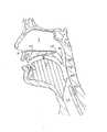
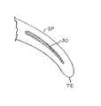
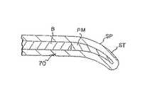
本発明の理解を容易とするために、いびきの力学について図1〜図4を参照して説明する。硬口蓋HPは舌Tに重なり、口Mの蓋を形成する。硬口蓋HPは骨サポートBを含んでおり、呼吸中に実質的に変形しない。軟口蓋SPは柔らかく、粘液膜、繊維および硬口蓋HPから後方へ延びる筋肉組織から構成されている。軟口蓋SPの先端LEは硬口蓋HPの後縁につながっている。軟口蓋SPの後縁TEは固定されていない。軟口蓋SPが構造的に骨または硬い軟骨によってサポートされていないため、軟口蓋SPは弛緩状態では弧状形状で硬口蓋HPの面から垂れ下がる。 To facilitate understanding of the present invention, the dynamics of snoring will be described with reference to FIGS. The hard palate HP overlaps the tongue T and forms the mouth M lid. The hard palate HP includes the bone support B and does not substantially deform during breathing. The soft palate SP is soft and is composed of a mucous membrane, fibers and muscle tissue extending backward from the hard palate HP. The tip LE of the soft palate SP is connected to the rear edge of the hard palate HP. The trailing edge TE of the soft palate SP is not fixed. Since the soft palate SP is not structurally supported by bone or hard cartilage, the soft palate SP has an arcuate shape in the relaxed state and hangs down from the surface of the hard palate HP.
咽頭空気路は口Mおよび鼻通路Nから気管TRへ空気を送る。軟口蓋SPの上面と喉壁の対向する面の間で規定される咽頭空気路の部分は鼻咽腔NPである。 The pharyngeal airway sends air from the mouth M and the nasal passage N to the trachea TR. The part of the pharyngeal airway defined between the upper surface of the soft palate SP and the opposing surface of the throat wall is the nasopharynx NP.
正常な呼吸中に、軟口蓋SPは図1に示す弛緩状態であり、鼻咽腔NPは妨害されず、空気は口Mと小鼻Nの両方から気管TRへ自由に流れる。 During normal breathing, the soft palate SP is in the relaxed state shown in FIG. 1, the nasopharynx NP is not obstructed, and air flows freely from both the mouth M and the nostril N to the trachea TR.
嚥下中に、軟口蓋SPは曲がり、かつ延びて(図2に示すように)鼻咽腔NPを閉じ、これによって口Mから小鼻通路Nへの流体の流れを阻止する。同時に、喉頭蓋EPは気管TRを閉じ、食物と飲料が食道ESへだけ通り、気管TRへは通らない。軟口蓋SPは鼻Nへの食物の逆流を阻害する弁である。軟口蓋SPは会話中に鼻Nへの空気流も調整する。軟口蓋SPがこのような重要な機能を果たすので、軟口蓋SPを外科的に変える従来技術はこれらの機能に悪影響を及ぼす。 During swallowing, the soft palate SP bends and extends (as shown in FIG. 2) to close the nasopharynx NP, thereby preventing fluid flow from the mouth M to the nostril passageway N. At the same time, the epiglottis EP closes the trachea TR, and food and beverages pass only to the esophagus ES and not to the trachea TR. The soft palate SP is a valve that inhibits the backflow of food to the nose N. The soft palate SP also regulates the airflow to the nose N during conversation. As the soft palate SP performs such important functions, conventional techniques of surgically altering the soft palate SP adversely affect these functions.
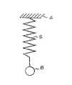
いびきの大半は前後に羽ばたく軟口蓋SPによって引き起こされる。呼吸が口を閉じて鼻Nを通してだけのものである場合には、軟口蓋SPの後縁TEは鼻咽腔空間NPに吸い込まれて空気路を妨害し、その後反復サイクルで空気路が開放する。口を開いた時、空気は軟口蓋SPの上下面を流れ、軟口蓋を上下に振動させ、口と鼻の通路M、Nの閉塞状態を交替する。いびきの音は空気路の素早い妨害と開放によって引き起こされるインパルスによって生じる。ファング他はいびきの間1秒に50回起こる空気通路の開閉を述べている。ファング他はばね質量モデル(図5)を利用して、空気流に対する軟口蓋の揺動を示している(ただし、軟口蓋は固定アンカAからばねSで垂れ下がるある質量を持つボールBである)。 The majority of snoring is caused by the soft palate SP flapping back and forth. If breathing is only with the mouth closed and through the nose N, the trailing edge TE of the soft palate SP is sucked into the nasopharyngeal space NP and obstructs the airway, after which the airway is opened in repeated cycles. When the mouth is opened, the air flows on the upper and lower surfaces of the soft palate SP, vibrates the soft palate up and down, and alternately closes the passages M and N between the mouth and the nose. The sound of snoring is caused by impulses caused by rapid obstruction and opening of the airways. Fang et al. Describe the opening and closing of an air passage that occurs 50 times a second during snoring. Fang et al. Utilize a spring-mass model (FIG. 5) to show the swinging of the soft palate with respect to airflow (where the soft palate is a ball B with a certain mass hanging from a fixed anchor A by a spring S).
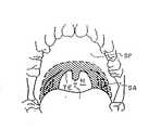
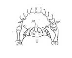
ファング他は軟口蓋の振動が起こる臨界空気流速度を効果的に上げるものとして咽喉形成に軟口蓋SPの短縮を類推している。図3の影の付いた部分SAは手順中に除去される軟口蓋SPの後縁TEの部分を示す。ファング他が提案する別の処置は、臨界空気流速度に影響を与える表面の傷によって軟口蓋SPの可撓性を減らすものである。図4の影の付いた部分SA'はこの処置によって傷付けられる部分を示す。図4において、破線Lは軟口蓋と硬口蓋の間の境界を示す。 Fang et al. Analogize the shortening of the soft palate SP for throat formation as an effective way to increase the critical airflow velocity at which the vibration of the soft palate occurs. The shaded portion SA in FIG. 3 indicates the portion of the trailing edge TE of the soft palate SP that is removed during the procedure. Another treatment proposed by Fang et al. Reduces the flexibility of the soft palate SP by surface scratches affecting the critical airflow velocity. The shaded area SA ′ in FIG. 4 indicates the area that is damaged by this procedure. In FIG. 4, a broken line L indicates a boundary between the soft palate and the hard palate.
軟口蓋SPの便利なモデルとして図5のばね質量モデルを使用すると、本発明はモデルの要素を変え、これによって空気流に対する軟口蓋SPの動的応答を変える軟口蓋SPへの外科埋め込み物に向けられている。埋め込み物はモデル(図5のボールB)の質量、ばねSのばね定数、ばねSの減衰、またはこれらの要素の任意の組合せを変えることができる。従来技術の外科技法と異なり、説明する埋め込み物は小さい切れ目に挿入しやすいものであり、患者の苦痛を緩和することができ、患者の刺激物として(ファング(Huang)他の表面の傷などのように)口の内部に露出されない。また、説明するように、動的再モデル化の度合いは細かく調整でき、過剰な解剖変更の必要性を回避し、悪い結果が起こった場合に、元に戻せる。 Using the spring-mass model of FIG. 5 as a convenient model of the soft palate SP, the present invention is directed to surgical implants in the soft palate SP that change the elements of the model, thereby changing the dynamic response of the soft palate SP to airflow. I have. The implant can change the mass of the model (ball B in FIG. 5), the spring constant of spring S, the damping of spring S, or any combination of these elements. Unlike prior art surgical techniques, the implants described are easy to insert into small cuts, can relieve the patient's pain, and can be used as patient irritants (such as Huang et al. So that it is not exposed inside the mouth. Also, as explained, the degree of dynamic remodeling can be fine-tuned, avoiding the need for excessive anatomical changes, and reverting if bad results occur.
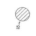
図6〜図7は本発明の第一実施形態を示し、ある質量の個々のユニット10(球や他の形状の埋め込み物のような埋め込み可能なモジュラ・デバイス)が後縁TEの近くで軟口蓋SPに埋め込まれる。図5のモデルを参照すると、球はある質量を質量ばねシステムに追加することになり、これによって空気流に対する動的応答を変え、移動や加速に対する抵抗力を与える。ある質量のユニット10の追加は軟口蓋の重心の位置も変え、モデルと動的応答を変える。 6 to 7 show a first embodiment of the invention in which an
図6〜図10の実施形態は、特別の患者に対して調整できるもので、複数のモジュール10を埋め込むことができる(図7に示す)。これにより、変更された動的応答が、いびきを誘発する振動を正常な空気流で発生させなくなるように、外科医が植込みモジュール10の数を徐々に増やすことを可能とする。個々のモジュール10は、ファング他が提案する咽喉形成のための荒い解剖破壊面積や表面の大きい傷面積よりもはるかに小さい縫合された個々の傷を介して軟口蓋SPに埋め込まれる。 The embodiment of FIGS. 6 to 10 can be tailored for a particular patient and can have
好ましくは、ある質量を持つこのようなモジュール10は放射線不透過性(または、ラジオマーク(radio−marked)されたものであり、磁気共鳴画像化(MRI)と互換性のある生体親和性材料の球のような中実モジュールである。チタンはこのような材料である。非限定的な例によれば、ある質量を持つモジュール10は直径約2mm〜4mmである。純粋な非焼結チタンの場合、それぞれのこのような球10は0.15〜1.22gmの質量を軟口蓋SPの後縁TEに追加し、軟口蓋SPの質量分布の再モデル化に寄与する。別材料の例は任意の生体親和性セラミックである。 Preferably, such a
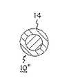
図9に示すように、球(図8のバージョン10と区別するため10'の符号が付けられている)は全体的に焼結されるか、その外面に生体組織成長を誘発する材料12を備えている。このような材料は焼結した外面か、ポリエステル繊維ジャケットのような被覆、またはカバーである。このような材料により生体組織の成長を可能とし、促進して、埋め込み物10'を定置する。また、埋め込み物10または10'の埋め込みは、軟口蓋SPを硬くするように作用する繊維形成反応を誘起する(また移動および加速に対する動的応答と抵抗をさらに変える)。焼結または被覆された球10'は繊維形成反応とその結果として生じる硬化を強化する。 As shown in FIG. 9, the sphere (labeled 10 'to distinguish it from
成長する生体組織および強化された繊維形成反応は上述の利益を有している一方、このような実施形態は逆に取り除くことが望まれる場合には埋め込み物10'を取り除きにくくする。したがって、別の方法として図10に示すように、球(埋め込み物10、10'と区別するため10"の符号が付けられている)は滑らかな被覆14(パリレンまたはPTFEなど)で覆われ、繊維形成を軽減する。 While growing biological tissue and the enhanced fiber-forming reaction have the benefits described above, such embodiments make it difficult to remove implant 10 'if removal is desired. Thus, as an alternative, as shown in FIG. 10, the spheres (labeled 10 ″ to distinguish them from the
図6〜図10の実施形態は、動的応答を再モデル化するために、図5のばね質量システムに質量を追加するか、質量の再配置をする。質量の量は動的応答を変化させるように選択されるが、嚥下中に鼻通路Nを閉塞するために軟口蓋SPが移動されることを妨げないように選択される。繊維形成反応と切れ目治療により、モデルのばねSが硬化する。 The embodiments of FIGS. 6-10 add mass or relocate the mass to the spring mass system of FIG. 5 to remodel the dynamic response. The amount of mass is selected to change the dynamic response, but not so as to prevent the soft palate SP from being moved to occlude the nasal passage N during swallowing. The fibril forming reaction and the break treatment cure the model spring S.
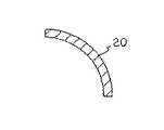
ばね質量システムの質量配置を修正することに加えて、図5のばね構成部品Sを修正し、(単独で、または質量修正と組み合せて)動的応答を変えることができる。図11〜図16は軟口蓋に配置される可撓性のストリップの形での埋め込み物20を示している。本明細書で「ストリップ」という言葉を使うことは長くて、細い埋め込み物に限定する意図ではなく、軟口蓋SPの動的モデルを変えるために埋め込まれるプレートその他の形状を含むものである。細長いストリップが埋め込みを容易とするための好ましい形状と現在推測されている。 In addition to modifying the mass configuration of the spring mass system, the spring component S of FIG. 5 can be modified to change the dynamic response (alone or in combination with the mass correction). 11 to 16 show the
ストリップ20は長手方向寸法よりも短い横方向寸法を有する。非限定的な例によれば、ストリップは約20mm〜30mmの長さLS、約2mm〜4mmの厚さTSと5mm〜10mmの幅WSを有する。図11に示すように、ストリップ20は軟口蓋SPに埋め込まれ、長手方向寸法LSは硬口蓋HPの隣接部から軟口蓋SPの後縁TEへ延びている。図12に示すように、複数のストリップ20が後方へ真っ直ぐ延びるか、後方へ延びつつ傾いて軟口蓋SPに埋め込まれる。ストリップ20は真っ直ぐ(図14)に形成されるか、軟口蓋の側断面形状に近似する自然形状を弛緩状態で有するように予め形が整えられている(図15)。
ストリップ20は任意の可撓性、生体親和性材料であり、放射線不透過性または放射能マークされたものおよびMRI互換材料であることが好ましい。ストリップ20は弾性を必要とせず、これらをこれらの元の形状に偏倚する材料ばね定数を有する必要はない。このようなストリップ20は可撓性なだけでよく、軟口蓋SPを補強し、空気流による変形に対する抵抗力を補助するために軟口蓋SPよりも硬い可塑的に変形可能なストリップである。軟口蓋SPのこのような硬化は図5のばね質量システムのばねSを硬くし、減衰し、軟口蓋SPの動的応答を変える。ストリップ20はばね定数を有するばねで、軟口蓋SPの変形にさらに抵抗し、軟口蓋SPを図5の弛緩状態に偏倚する物であってもよい。ストリップ20の硬さ、ストリップ20のばね定数、およびストリップ20の数は嚥下中に軟口蓋SPが閉じるのを防げることを回避するように選択される。適する材料の例はチタンおよびニチノールを含んでいる(周知のニッケル・チタン合金)。図9および図10のように、ストリップ20は生体組織成長表面が備えられたり、必要に応じ、被覆されたりする。また、ストリップを構造的に修正し、その可撓性を制御できる。図16において、ストリップ20の底部22(配置後舌に面する)に横方向切れ込み24を備え、配置した後にストリップ20の上方への曲がりやすさよりも下方への曲がりやすさを強化する。
図17は図13のストリップ20の別の形態を提供する。図17において、ストリップ20'はアクセス開口30を持つ内部空間28を有するハウジング26を含んでいる。内部空間28はハウジング26の長手方向に延びている。ストリップ20'はアクセス開口30を通り、空間28へ挿入されるサイズにされた長手方向挿入物32をさらに含んでいる。非限定的な例によれば、ハウジング26はシリコーン・ゴム(位置を示す放射能マーカ(図示せず)付き)であり、挿入物32はチタン・ロッドまたはその他の可撓性部材である。図17の実施形態では、ハウジング26(挿入物がない)は軟口蓋SPに埋め込まれる。ハウジング26は硬化ストリップとして独立に作用し、軟口蓋SPに硬さを追加し、軟口蓋の動的応答を変える。さらに硬化が必要であったり、ばね作用が必要な場合は、最初の手術時またはその後の処置で空間28に挿入物32を挿入することによって、患者特有の動的モデルに対して埋め込み物20'を選択的に調整することができる。図17の実施形態により、空間28に挿入されるべき希望する特性(例えば、硬さおよびばね作用)の挿入物32が選択できるように、且つ希望するような動的応答に変えるように、挿入物32を広い範囲の材料および構造から選択することが可能となる。図17の実施形態は挿入物32の後での除去、および軟口蓋の動的応答の術後修正のため別特性の別な挿入物32との交換も可能としている。 FIG. 17 provides another form of the
図18の実施形態は図17のものと類似している。ハウジング26'は複数の、平行に配置された内部空間28'とアクセス開口30'を備える。図17の実施形態の機能と利益の他に、挿入物32の数を変更し、軟口蓋SPの動的応答を変えたり、調節できたりする。 The embodiment of FIG. 18 is similar to that of FIG. The housing 26 'has a plurality of parallel arranged interior spaces 28' and access openings 30 '. In addition to the features and benefits of the embodiment of FIG. 17, the number of
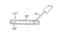
図19はストリップ埋め込み物のさらに他の実施形態を示す。図19において、ストリップ20'''は内部空間28"により規定される可撓性合成材料の完全に寸法の決められた密封体の形でのハウジング26"を有する袋状のものである。袋状体26"は針により内部に液体が注入された後に自己密閉することが好ましい。液体がハウジング26"中に射出され(例えば、皮下注射針40からの射出によって)、ストリップ20'''を硬くする。流体を追加するとストリップ20'''をさらに硬くし、軟口蓋SPの動的応答をさらに変える。流体の除去は可撓性を増やす。図17の実施形態(挿入物32が手術後に切れ目を介して最も効果的に交換され、軟口蓋SPの可撓性を変える)とは異なり、図19の実施形態により針による注射によって軟口蓋SPの可撓性を選択的に変更できる。図19の別の方法は、空間28"にいわゆる位相変更ポリマを充填し、空間28"に硬化剤を射出して、ポリマの可撓性を変える。 FIG. 19 shows yet another embodiment of a strip implant. In FIG. 19, the strip 20 '' 'is a pouch having a
図20〜図23は本発明のさらに他の実施形態を示す。上述の実施形態において、図5のばね質量システムは軟口蓋SPの質量を変えるか、軟口蓋SPのばね特性を変えることによって変えられる。動的応答は、ばね質量システムに作用する力を変えることによっても変えることができる。すなわち、軟口蓋SPに作用する力は軟口蓋の表面上の空気流によって生じる。軟口蓋はこのような空気流に応じて揚力を生じる翼として作用する。軟口蓋SPの長手方向(すなわち、前方から後方への)断面形状を修正することにより、流体力学的応答、したがって、動的応答が変えられる。 20 to 23 show still another embodiment of the present invention. In the embodiment described above, the spring mass system of FIG. 5 is changed by changing the mass of the soft palate SP or by changing the spring characteristics of the soft palate SP. The dynamic response can also be changed by changing the force acting on the spring mass system. That is, the force acting on the soft palate SP is generated by the air flow on the surface of the soft palate. The soft palate acts as a wing that generates lift in response to such airflow. By modifying the longitudinal (ie, front-to-back) cross-sectional shape of the soft palate SP, the hydrodynamic response, and thus the dynamic response, is altered.
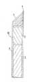
図20〜図23の実施形態において、埋め込み物30は切れ目により軟口蓋SPに挿入される。埋め込み物30は楕円形を有しており、軟口蓋SPの形状の変形を引き起こす。埋め込み前に、埋め込み物30の挿入を容易とするため(図20および図22)平らな楕円形に形成されるのが好ましい。埋め込み後、埋め込み物30は楕円形に拡張される(図21および図23)。このような拡張が機械的に(すなわち、バルーン拡張により)達成される一方、埋め込み物30が身体の暖かさに応じて拡張される形状記憶合金(ニチノールのような)として形成されることも好ましい。軟口蓋SPの流体力学特性を変更する他に、埋め込み物30を希望に応じた質量および硬さで構成し、図5のばね質量システムのばねおよび質量構成を変えることができる。 In the embodiment of FIGS. 20 to 23, the
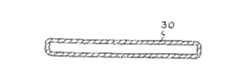
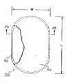
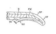
図24〜図32は拡張可能な装置50と、小さい切れ目を介して軟口蓋SPに埋め込み物50を挿入するための挿入ツール60を示している。図24および図25において、埋め込み物50は、例えば、ポリエステル繊維54などの可撓性材料の形で繊維形成誘起物を備えた可撓性リム52として最も良く示されている。リム52はチタンその他の材料であり、完全に拡張された状態で幅Wと長さLを有する図24の楕円として示される自然形状に弾性的に偏倚されている。楕円が好ましい形状として図示されているが、他の形状でもよい。形状は軟口蓋SPの形を変えるよう選択された形状を含んでいてもよい。ポリエステル繊維54(Dacron(R)など)は繊維形成および組織統合のための隙間空間を含んでおり、軟口蓋SPを硬くする。 FIGS. 24-32 show the
軟口蓋SPが図29〜図32に略示されており、口蓋筋肉PMが硬口蓋の骨Bから延びており、軟口蓋SPの柔らかい組織STに覆われている。埋め込み物50は埋め込み物50をリム52の偏倚に抗して長さLのコンパクトなシリンダ状の形に圧縮し、圧縮された埋め込み物50はシリンダ状の挿入ツール60の遠隔端部に配置される。ツール60の遠隔端部62は切れ目に従った鈍い傾斜端部であり、チップ62が前進するにつれて、組織を分離する。ロッド64は埋め込み物50に近接して配置される。遠隔端部62は、プッシュ・ロッド64が埋め込み物50を遠隔端部62から押し出すように切断可能である。挿入ツール60から押し出された時、埋め込み物50はバネ性により楕円形状に戻る。 The soft palate SP is schematically illustrated in FIGS. 29 to 32, and the palatal muscle PM extends from the hard palate bone B and is covered by the soft tissue ST of the soft palate SP. The
埋め込み物50は軟口蓋に小さい切れ目70を形成することによって挿入される。図29において、切れ目は軟口蓋の下面に形成される。この処置は軟口蓋の上面から行うこともできる。切れ目は拡張された埋め込み物50の全幅Wよりもかなり小さいツール60の遠隔端部62を通すサイズである。 The
適切な鈍い切断ツールを切れ目70に挿入し、拡張された埋め込み物50を受け入れるのに十分な量だけ口蓋筋肉PMから柔らかい組織STを分離する。遠隔端部62は切れ目70を介して挿入され、遠隔端部62が柔らかい組織STと口蓋筋肉PMを分離しつつ軟口蓋SPに沿って前進する(図30)。ツール60はツール60の位置を医者の触診により、あるいは任意の視覚化技法(例えば、遠隔端部62の内視鏡)によって確認することにより前進させることができる。遠隔端部62が完全に前進した時、ツール60の外筒66が引っ込められ、代わりのホールド・ロッド64が埋め込み物50を遠隔端部62から排出させる。埋め込み物50が完全に排出されると、ツール60が切れ目70から除去される。解放された埋め込み物50は次いで楕円形に拡張され、口蓋筋肉PMと柔らかい組織STの間に位置する(図31および図32)。 A suitable blunt cutting tool is inserted into the
埋め込み物50の繊維54は軟口蓋SPの繊維形成および硬化を促進する。小さい切れ目70から潰れた埋め込み物50を挿入することにより、大表面積の繊維形成(および大きい硬化)を最小の切れ目70で達成できる(患者の苦痛を軽減する)。また、埋め込み物50が弾性的に拡張可能なものとして示されているが、埋め込み物50は形状記憶合金(例えば、ニチノール)、スマート・ポリマ、バルーン拡張材および可塑的に変形可能な金属などの他の要因に応じて拡張するか、膨張するものでもよい。 The
上述の別の方法として、カテーテル(図示せず)を切れ目70を介して、軟口蓋SPに沿って通すことができる。挿入ツール60はカテーテルを通ることができる。必要に応じ、芯ツール(図示せず)をカテーテルによって通し、埋め込み物50(または、先の実施形態の装置)の配置前に軟口蓋SPから組織を除去する。また、小さい埋め込み物の場合、埋め込み物は、ニードルポークを通して軟口蓋に挿入された短い筒を通して挿入することができるが、予備切開を行う必要はない。 Alternatively, a catheter (not shown) can be passed through
図33〜図36を参照すると、本発明のさらに他の実施形態が説明されている。図33〜図36において、シリンダ状の形を有する埋め込み物80が示されている。形は例示的なものに過ぎない。埋め込み物80は前に説明したように挿入ツール60によって挿入される。 Referring to FIGS. 33-36, yet another embodiment of the present invention is described. 33-36, an
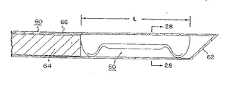
埋め込み物80は二つの硬化構成部品を含んでいる。第一の構成部品82は編まれたシリンダ状の形に形成された生体吸収性構造のような生体吸収性材料のベースである。このような材料は柔らかい組織よりも硬さが大きく、時間がたつと身体に吸収される。このような材料の例はエチコン社がPDSIIの商標で販売しているポリジオクサノン縫合糸のような合成吸収可能縫合糸である。別材料は吸収可能生化学接着剤を含んでいる。説明した第一の構成部品は直ちに術後硬化を提供し、軟口蓋への埋め込み物80の埋め込み直後にいびきを軽減したり、なくしたりする。 The
第二の構成部品84は第一の構成部品82と組み合わされた任意の繊維形成誘起材料である。非限定的な例によれば、第二の構成部品は第一の構成部品82の隙間空間に織り込まれたポリエステルまたはポリエステル繊維(Dacron(R)のような)のフィラメントである。軟口蓋SPの柔らかい組織における第二の構成部品84の存在は軟口蓋を硬化する繊維形成を誘起し、いびきを軽減したり、なくしたりする。この硬化は埋め込み後の時間とともに増加し、繊維形成反応が定常状態になるまで増加する。ポリエステルの第二の構成部品84は恒久的なものであり、生体吸収性ではない。したがって、繊維形成効果(それ故、いびき軽減効果)は、埋め込まれて第一の構成部品82が完全に吸収された後も恒久的に続く。
第一の構成部品82と第二の構成部品84は埋め込み物80として協働し、術後直後およびその後長く効果的な硬化をもたらす。第一の構成部品は埋め込み時に軟口蓋SPを硬化する硬い材料である。しかし、時間がたつと、第一の構成部品は吸収され、硬化効果が減ったり、なくなったりする。第二の構成部品84は埋め込み物10の埋め込み時に直ちには軟口蓋をほとんど硬化しない極めて可撓性の材料で形成されている。しかし、時間によって、第二の構成部品84の材料によって誘起される繊維形成は軟口蓋を硬くする。この現象は横軸が時間を表し、縦軸が埋め込み物10によって提供される硬化を表す図36のグラフに示されている。線Aは第一の構成部品82による硬化(これは第一の構成部品が吸収された時に、ゼロに減衰する)である。線Bは第二の構成部品による硬化(これは埋め込み時にほぼゼロであり、繊維形成の定常状態レベルを表す最大値まで増加する)を表す。線Cは線Aと線Bの硬化の合計である軟口蓋SPの硬化を表す。 The
したがって、埋め込み物80の実施形態の場合、術後硬化(およびいびきの消滅)が直ちに達成される。長期にわたる硬化が、恒久的な繊維形成反応によって提供される。第二の構成部品84の繊維形成が増えるにつれて、第一の構成部品82が吸収されるので、総硬化が制御される。 Thus, for the embodiment of the
図37〜図39は軟口蓋SPに装置を挿入する別の挿入システム100を示す。図37〜図39はシリンダ状の埋め込み物102(図34の埋め込み物80または装置など)の新規な挿入システム100の使い方を示す。しかし、図37〜図39を参照して説明する方法および装置は他の形状(例えば、図7の球形埋め込み物または図13の矩形断面埋め込み物)および図24の埋め込み物50のような拡張可能埋め込み物にも使用できる。 37-39 show another
軟口蓋の組織に突き刺すための地表傾斜遠隔端部61'を有する針66'を備えている。針66'は中空であり、スライドする閉ざされた隙間で埋め込み物102を搬送する。ロッド64'が、針66’内で埋め込み物102に近接してスライド自在に配置されている。図26〜図32を参照して上述したように、埋め込み物102は軟口蓋内の希望する埋め込み位置まで針66'によって担持される。希望する位置において、埋め込み物102はロッド64'を定置保持しつつ針66'を引っ込めることによって挿入される。ロッド64'と針66'の間の相対運動により、ロッド64'が軟口蓋に対して埋め込み物102を動かす必要なしに針66'から埋め込み物102を排出する。 It has a needle 66 'with a sloping remote end 61' for piercing the soft palate tissue. The needle 66 'is hollow and carries the
軟口蓋を通して針66'を前進させるにつれて、組織と体液は針66'に入る傾向があり、後で針66'からの埋め込み物102の排出を妨害する。図26〜図27の実施形態は針66の遠隔端部にフラップ62を使用することによって針60への組織および流体のこのような進入を回避する。図38〜図39の実施形態は針66'への組織の進入を阻止する別技法を提供する。 As the needle 66 'is advanced through the soft palate, tissue and bodily fluids tend to enter the needle 66', which later prevents the ejection of the
図38〜図39において、針66'には針の遠隔端部61'にプラグ104が備えられている。好ましくは、プラグ104は生体吸収性材料(図34の埋め込み物80における第一の構成部品82の材料のような)である。針66'の遠隔端部61'にプラグ104を配置した後、遠隔端部61'を研磨し、図38〜図39に示す遠隔端部61’の形状の最終傾斜となるようにする。 38-39, the needle 66 'is provided with a
排出中に、ロッド64’(針66'の引っ込みによる)は針66'からプラグ104および埋め込み物102の両方を押し出す。プラグ104が生体吸収性であるため、時間がたつと患者の身体に吸収される。埋め込み物102は軟口蓋の動的応答を変えることに関してすでに述べた治療効果を提供する。 During ejection, rod 64 '(by retraction of needle 66') pushes both
プラグ104が針66'の近傍から内方に押し込まれるのを回避するために、針66'はロッド64'および埋め込み物102の直径に近い第一孔66a'と遠隔端部61'における第二孔66b'を含んでいる。第二孔66b'は第一孔66a'と同軸で、第一孔66a’よりも大きく、環状の保持縁部65'が、針66'内に規定されている。プラグ104は保持縁部65'に衝合し、針66'が軟口蓋の組織を通して前進した時に、針66'内へ押し込まれないようにする。 To prevent the
針66'は61'の遠隔端部において多孔であってもよく、装填された埋め込み物102を有する針が殺菌のため浸漬されるようにしてもよい。図43〜図44は多孔とするために透孔69'を有する多孔針端部の埋め込み物を示す。プラグ(プラグ104のような)は図43〜図44に示されておらず、針66'がプラグありでもなしでも使用できることを示す(この場合、針66'は一定直径の孔67'を有する)。多孔針の場合、組み立てるときに埋め込み物102を針の遠隔端部に予め装填できる。これは針に埋め込み物を装填するという面倒な仕事から医者を解放する。口蓋に埋め込み時に、あるいは定置埋め込みの少し前に、医者は抗生物質(周知の抗生物質ゲンタマイシンまたはベータデンのような)の溶液に針遠隔端部を浸漬してもよい。流体抗生物質は針の孔69'を通って流れ、埋め込み物102を浸漬する。結果として、抗生物質を予め取り扱えることと、針を埋め込み物の挿入の後に廃棄できることの組み合わせにより、組み合わせた針と埋め込み物を経済的に作成できる。装填中に、埋め込み物を針孔67'よりも大きなサイズにできる。したがって、埋め込み物は排出された後に拡張する。 Needle 66 'may be porous at the remote end of 61', and the needle with loaded
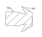
図40〜図41は捻られるか又は編まれた繊維103a、103bで形成された埋め込み物102'を示す。単一タイプの繊維も使用できる一方、この実施形態は、互いに編まれるか、捻られるかした二つの異なる繊維103a、103bで形成されるのが好ましい。一方の繊維103aは、繊維形成反応を促進するためのものであってもよい。このような繊維103aはポリエステルまたは絹縫合材料である(この場合、個々の繊維103aは編まれるか、捻られた要素で形成されていてもよい)。他の繊維103bは図33におけるように生体吸収性のファイバである(例えば、コラーゲンのような天然材料又は前述のPDS縫合材料のような合成材料を含む生体吸収性縫合材料)。あるいは、第二繊維103bはポリプロピレン縫合材料などの非吸収性材料であり、埋め込み物に追加硬さを与えるものであってもよい。繊維103a、103bは埋め込み物102'の軸方向に沿って一緒に結合され、追加硬さを与える。 Figures 40-41 show an implant 102 'formed of twisted or knitted
図42を参照し、図37の埋め込み物102を例にあげると、埋め込み物102の遠隔端部102a(すなわち、針66'から排出される埋め込み物102の第一の端部)は切れ込みを備えるか、針66'から排出された後に外方へ広がるアンカ103を備える。このような広がりは、成長する組織が成熟する際に、埋め込み物102を定位置に固定するのを助ける。このような広がりは、針の中に畳み込まれ、針の引き込み中に針66'に沿って埋め込み物が移動するときに、埋め込み物102上で放射状に広がる繊維によっても提供される。 Referring to FIG. 42, taking the
図40〜図41を参照して説明した撚り合せ(捻り又は編みこみ)作業は高い設計融通性を提供する。このような撚り合せは各種の機能に対応して多くの異なるタイプの繊維を合体させることができる。例えば、放射線不透過性の繊維は、撚り合せ物に、蛍光透視法下の埋め込み物の視覚化を可能にする機能を与える。このような撚り合わされた埋め込み物の構造(および可撓性)は、コア材料を追加するか、撚り合せの硬さを変えることによって変更できる。図40および図41ではコアまたは中央繊維105を示している。中央繊維105は繊維103a、103bのいずれかと同じ材料であってもよく、あるいは硬さまたは他の機械的特性を追加するため別の材料であってよい。例えば、繊維103a、103bが非吸収性材料であり、一方、コア105は生体吸収性材料であってもよい。コア105は、硬さを追加するか、放射線不透過性の金属材料であってもよい。コア105はコイルであるか、ばね形のコアであってもよい。撚り合わされた埋め込み物102'の構造において、全ての繊維103a、103bおよびコア105は埋め込み物102'と同じ位置に終端を持つことが好ましい。言い換えると、繊維103a、103bおよびコア105の端部は埋め込み物102'の軸方向端部に一致する。端部は熱処理されるか接着され、撚り合わされた埋め込み物102'がほぐれるのを阻止する。 The twisting (twisting or braiding) operation described with reference to FIGS. 40-41 provides high design flexibility. Such twisting can coalesce many different types of fibers for various functions. For example, radiopaque fibers provide the twist with the ability to allow visualization of the implant under fluoroscopy. The structure (and flexibility) of such twisted implants can be changed by adding core material or changing the hardness of the twist. 40 and 41 show the core or central fiber 105. The center fiber 105 may be the same material as any of the
埋め込み物が殺菌されなければならないことが理解されたい。埋め込み物および/または埋め込みデバイスは予め殺菌されて殺菌パックに収容された形で供給されるか、挿入前に適切な殺菌処理にさらされる。さらに、本明細書で開示される方法にしたがい本明細書で開示される埋め込み物を使用するための使用説明書をパックに含めることもできる。 It should be understood that the implant must be sterilized. The implant and / or implant device may be supplied pre-sterilized in a sterile pack or may be subjected to an appropriate sterilization process prior to insertion. Further, the pack can also include instructions for using the implants disclosed herein according to the methods disclosed herein.
上記の説明は、軟口蓋の動的応答を変える軟口蓋用の埋め込み物の発明の各種実施形態である。本発明は従来の外科治療よりも遥かに苦痛が少ないものである。さらに、本発明では、手術中および術後において選択的に調節する処置を行うことができるとともに、操作を逆にすることを可能とする。本発明を説明したが、他の変形例および実施形態を当業者は思い付くであろう。例えば、図13のストリップは、さらに硬くするためにタイトにできるコイルばねに納められていてもよい。このようなストリップは蝶番止めされたセグメントであってもよい。また、本発明は軟口蓋を硬くするため軟口蓋に配置される任意の繊維形成誘起物をカバーできる(例えば、熱処理あるいはエチル・アルコールなどの化学薬品塗布などを行うか又はそのままのポリエステル繊維、または軟口蓋に恒久的な傷を作り出す態様でのこのような塗布)。例えば、このような化学品が切れ目70を介して挿入されるか、又は熱源が切れ目70を介して挿入されてもよい。硬化が恒久的なものであるから、効力を持続するために本発明を繰り返す必要はない。このような変形および同等物は首記特許請求の範囲の範囲内である。 The above description is various embodiments of the invention for a soft palate implant that alters the dynamic response of the soft palate. The present invention is much less painful than conventional surgical treatments. Further, according to the present invention, it is possible to perform a treatment for selectively adjusting during and after surgery, and to make it possible to reverse the operation. Having described the invention, other variations and embodiments will occur to those skilled in the art. For example, the strip of FIG. 13 may be housed in a coil spring that can be tight to make it even harder. Such a strip may be a hinged segment. Also, the present invention can cover any fiber formation inducer placed on the soft palate to harden the soft palate (e.g., by heat treatment or by applying a chemical such as ethyl alcohol or the like polyester fiber, or to the soft palate) Such application in a manner that creates a permanent wound). For example, such a chemical may be inserted through the
Claims (56)
Translated fromJapanese固形状の生体親和性材料からなり、少なくとも一部が生体吸収性ではない埋め込み物を含み、
前記埋め込み物の寸法及び形状が、患者の気道を形成する生体組織に埋め込み可能になされており、
前記埋め込み物が、少なくとも前記埋め込み物により誘起される繊維形成反応との連携により、前記生体組織の外部から力を加えることなく空気流に対する前記生体組織の動的応答を変えるための機械的特性を有することを特徴とする装置。A device used to treat a condition of the respiratory tract,
Consisting of a solid biocompatible material, at least partially including a non-bioabsorbable implant,
The size and shape of the implant are adapted to be implantable in biological tissue forming a patient's airway;
The implant, at least in conjunction with the fiber-forming reaction induced by the implant, provides a mechanical property for altering the dynamic response of the biological tissue to an airflow without applying force from outside the biological tissue. An apparatus comprising:
Applications Claiming Priority (12)
| Application Number | Priority Date | Filing Date | Title |
|---|---|---|---|
| US09/398,991US6250307B1 (en) | 1999-09-17 | 1999-09-17 | Snoring treatment |
| US09/434,653US6401717B1 (en) | 1999-09-17 | 1999-11-05 | Snoring treatment |
| US09/513,432US6450169B1 (en) | 1999-09-17 | 2000-02-25 | Braided implant for snoring treatment |
| US09/513,039US6415796B1 (en) | 1999-09-17 | 2000-02-25 | Placement tool for snoring treatment |
| US09/513,042US6453905B1 (en) | 1999-09-17 | 2000-02-25 | Multi-component snoring treatment |
| US09/602,141US6390096B1 (en) | 1999-09-17 | 2000-06-23 | Needle with pre-loaded implant for snoring treatment |
| US09/398991 | 2000-06-23 | ||
| US09/513042 | 2000-06-23 | ||
| US09/513432 | 2000-06-23 | ||
| US09/602141 | 2000-06-23 | ||
| US09/434653 | 2000-06-23 | ||
| US09/513039 | 2000-06-23 |
Related Parent Applications (1)
| Application Number | Title | Priority Date | Filing Date |
|---|---|---|---|
| JP2000282615ADivisionJP3745606B2 (en) | 1999-09-17 | 2000-09-18 | Snoring implant |
Publications (2)
| Publication Number | Publication Date |
|---|---|
| JP2004154583Atrue JP2004154583A (en) | 2004-06-03 |
| JP4699690B2 JP4699690B2 (en) | 2011-06-15 |
Family
ID=56290053
Family Applications (2)
| Application Number | Title | Priority Date | Filing Date |
|---|---|---|---|
| JP2000282615AExpired - Fee RelatedJP3745606B2 (en) | 1999-09-17 | 2000-09-18 | Snoring implant |
| JP2003403694AExpired - LifetimeJP4699690B2 (en) | 1999-09-17 | 2003-12-02 | Implants for the treatment of airway conditions |
Family Applications Before (1)
| Application Number | Title | Priority Date | Filing Date |
|---|---|---|---|
| JP2000282615AExpired - Fee RelatedJP3745606B2 (en) | 1999-09-17 | 2000-09-18 | Snoring implant |
Country Status (11)
| Country | Link |
|---|---|
| EP (1) | EP1216013B1 (en) |
| JP (2) | JP3745606B2 (en) |
| CN (1) | CN100435761C (en) |
| AT (1) | ATE331491T1 (en) |
| AU (1) | AU8038700A (en) |
| CA (1) | CA2381904C (en) |
| DE (3) | DE60029111T2 (en) |
| ES (1) | ES2265993T3 (en) |
| GB (1) | GB2355936B (en) |
| HK (1) | HK1047878A1 (en) |
| NO (1) | NO318637B1 (en) |
Cited By (5)
| Publication number | Priority date | Publication date | Assignee | Title |
|---|---|---|---|---|
| JP2008526286A (en)* | 2005-01-04 | 2008-07-24 | クリニカム・デル・ユニフェルシタット・レーゲンスブルク | Implantable device for non-pneumatic and adjustable placement of parts of the human or animal body |
| JP2010505512A (en)* | 2006-10-03 | 2010-02-25 | リストア・メディカル・インコーポレーテッド | Tongue implant |
| JP2011508650A (en)* | 2008-01-03 | 2011-03-17 | レベント メディカル インコーポレイテッド | Partially erosive system for the treatment of obstructive sleep apnea |
| JP2012508600A (en)* | 2008-11-17 | 2012-04-12 | ツァン,シャンミン | Adjustable soft palate support and implantation method |
| JP2013531516A (en)* | 2010-06-03 | 2013-08-08 | コーニンクレッカ フィリップス エレクトロニクス エヌ ヴィ | Tongue shaping implant tension release system |
Families Citing this family (57)
| Publication number | Priority date | Publication date | Assignee | Title |
|---|---|---|---|---|
| US6523541B2 (en)* | 1999-09-17 | 2003-02-25 | Pi Medical, Inc. | Delivery system for snoring treatment implant and method |
| US6601584B2 (en)* | 1999-09-17 | 2003-08-05 | Pi Medical, Inc. | Contracting snoring treatment implant |
| US6523542B2 (en) | 1999-09-17 | 2003-02-25 | Pi Medical, Inc. | Snoring treatment implant and method |
| US6513530B2 (en)* | 1999-09-17 | 2003-02-04 | Pi Medical, Inc. | Braided palatal implant for snoring treatment |
| HK1047878A1 (en)* | 1999-09-17 | 2003-03-14 | Restore Medical, Inc. | Implants and methods for snoring treatment |
| US6513531B2 (en) | 1999-09-17 | 2003-02-04 | Pi Medical, Inc. | Proximal placement of snoring treatment implant |
| US6250307B1 (en) | 1999-09-17 | 2001-06-26 | Pi Medical, Inc. | Snoring treatment |
| US6390096B1 (en) | 1999-09-17 | 2002-05-21 | Pi Medical, Inc. | Needle with pre-loaded implant for snoring treatment |
| US6450169B1 (en) | 1999-09-17 | 2002-09-17 | Pi Medical, Inc. | Braided implant for snoring treatment |
| US6502574B2 (en) | 1999-09-17 | 2003-01-07 | Pi Medical, Inc. | Lateral stiffening snoring treatment |
| US6516806B2 (en) | 1999-09-17 | 2003-02-11 | Pi Medical, Inc. | Compliant snoring treatment implant |
| WO2004021870A2 (en)* | 2002-09-06 | 2004-03-18 | Apneon, Inc. | Magnetic force devices, systems, and methods for resisting tissue collapse within the pharyngal conduit |
| US20050154412A1 (en)* | 2003-09-19 | 2005-07-14 | Restore Medical, Inc. | Airway implant and delivery tool |
| USD536792S1 (en) | 2003-09-19 | 2007-02-13 | Restore Medical, Inc. | Implant delivery tool |
| NZ550020A (en) | 2004-02-26 | 2011-02-25 | Linguaflex Llc | A tissue retractor for treatment of a breathing disorder comprising a shaft, a retractor, and an anchor |
| US10524954B2 (en) | 2004-02-26 | 2020-01-07 | Linguaflex, Inc. | Methods and devices for treating sleep apnea and snoring |
| US8371307B2 (en) | 2005-02-08 | 2013-02-12 | Koninklijke Philips Electronics N.V. | Methods and devices for the treatment of airway obstruction, sleep apnea and snoring |
| US8096303B2 (en) | 2005-02-08 | 2012-01-17 | Koninklijke Philips Electronics N.V | Airway implants and methods and devices for insertion and retrieval |
| EP2561842A1 (en)* | 2006-07-06 | 2013-02-27 | Quiescence Medical Inc | Apparatus for treating sleep apnea |
| US7780730B2 (en) | 2006-09-25 | 2010-08-24 | Iyad Saidi | Nasal implant introduced through a non-surgical injection technique |
| US20080078411A1 (en) | 2006-10-03 | 2008-04-03 | Restore Medical, Inc. | Tongue implant for sleep apnea |
| US10842653B2 (en) | 2007-09-19 | 2020-11-24 | Ability Dynamics, Llc | Vacuum system for a prosthetic foot |
| US9439801B2 (en) | 2012-06-29 | 2016-09-13 | Revent Medical, Inc. | Systems and methods for treatment of sleep apnea |
| WO2009140197A1 (en) | 2008-05-12 | 2009-11-19 | Revent Medical, Inc. | Partially erodable systems for treatment of obstructive sleep apnea |
| JP2009273610A (en)* | 2008-05-14 | 2009-11-26 | Toshihiko Sato | Ic tag with indwelling function |
| US8678008B2 (en) | 2008-07-30 | 2014-03-25 | Ethicon, Inc | Methods and devices for forming an auxiliary airway for treating obstructive sleep apnea |
| US8413661B2 (en) | 2008-08-14 | 2013-04-09 | Ethicon, Inc. | Methods and devices for treatment of obstructive sleep apnea |
| AU2009287269B2 (en)* | 2008-08-29 | 2014-11-27 | Xiangmin Zhang | Implantable soft palate support and implantation method |
| EP2344093B1 (en) | 2008-10-16 | 2021-03-31 | Linguaflex, Inc. | Devices for treating sleep apnea |
| US9597220B2 (en) | 2008-11-19 | 2017-03-21 | Spirox, Inc. | Apparatus and methods for correcting nasal valve collapse |
| US8800567B2 (en) | 2008-12-01 | 2014-08-12 | Ethicon, Inc. | Implant systems and methods for treating obstructive sleep apnea |
| US8783258B2 (en) | 2008-12-01 | 2014-07-22 | Ethicon, Inc. | Implant systems and methods for treating obstructive sleep apnea |
| CA2746218A1 (en)* | 2008-12-09 | 2010-06-17 | H-Medical | Apparatus, systems, and methods for constraining and/or supporting tissue structures along an airway |
| EP2204148B1 (en) | 2008-12-30 | 2012-03-28 | Medartis AG | Implant for treatment of obstructive sleep apnea |
| US8371308B2 (en) | 2009-02-17 | 2013-02-12 | Ethicon, Inc. | Magnetic implants and methods for treating an oropharyngeal condition |
| US9326886B2 (en) | 2009-10-29 | 2016-05-03 | Ethicon, Inc. | Fluid filled implants for treating obstructive sleep apnea |
| US9877862B2 (en) | 2009-10-29 | 2018-01-30 | Ethicon, Inc. | Tongue suspension system with hyoid-extender for treating obstructive sleep apnea |
| US9974683B2 (en) | 2009-10-30 | 2018-05-22 | Ethicon, Inc. | Flexible implants having internal volume shifting capabilities for treating obstructive sleep apnea |
| EP2547296A4 (en) | 2010-03-19 | 2014-08-06 | Revent Medical Inc | Systems and methods for treatment of sleep apnea |
| WO2011116384A2 (en) | 2010-03-19 | 2011-09-22 | Revent Medical, Inc. | Systems and methods for treatment of sleep apnea |
| AU2011255195A1 (en) | 2010-05-21 | 2012-11-29 | Revent Medical, Inc. | Systems and methods for treatment of sleep apnea |
| WO2012018545A2 (en) | 2010-07-26 | 2012-02-09 | Revent Medical, Inc. | Systems and methods for treatment of sleep apnea |
| US8905033B2 (en) | 2011-09-28 | 2014-12-09 | Ethicon, Inc. | Modular tissue securement systems |
| US9161855B2 (en) | 2011-10-24 | 2015-10-20 | Ethicon, Inc. | Tissue supporting device and method |
| US8973582B2 (en) | 2011-11-30 | 2015-03-10 | Ethicon, Inc. | Tongue suspension device and method |
| US10470760B2 (en) | 2011-12-08 | 2019-11-12 | Ethicon, Inc. | Modified tissue securement fibers |
| US9173766B2 (en) | 2012-06-01 | 2015-11-03 | Ethicon, Inc. | Systems and methods to treat upper pharyngeal airway of obstructive sleep apnea patients |
| ES2671997T3 (en) | 2013-02-27 | 2018-06-12 | Spirox, Inc. | Nasal implants and systems |
| US9855164B2 (en)* | 2013-03-06 | 2018-01-02 | Ethicon, Inc. | Method and device for treating obstructive sleep apnea |
| US10531979B2 (en) | 2013-03-15 | 2020-01-14 | Fabian Hermann Urban Füglister | Tongue deformation implant |
| WO2016033196A1 (en) | 2014-08-26 | 2016-03-03 | Spirox, Inc. | Nasal implants and systems and method of use |
| KR102755866B1 (en) | 2015-09-25 | 2025-01-17 | 스트리커 코포레이션 | Nose Implant |
| JP6007379B1 (en)* | 2015-12-10 | 2016-10-12 | 株式会社壮健 | Auxiliary device to improve sleep apnea syndrome |
| CN109068955B (en) | 2016-05-02 | 2022-10-28 | 茵泰勒斯医疗公司 | Nasal valve implant and method of implanting the same |
| US12016583B2 (en) | 2016-12-13 | 2024-06-25 | Linguaflex, Inc. | Tongue retractor |
| CN106726090B (en)* | 2016-12-22 | 2021-11-23 | 北京品驰医疗设备有限公司 | Rechargeable snoring sleep apnea prevention system |
| US20230007905A1 (en)* | 2019-12-10 | 2023-01-12 | Medartis Holding Ag | Apparatus and method for piercing a soft tissue canal in a body part and implant for insertion into a soft tissue canal in a body part |
Citations (7)
| Publication number | Priority date | Publication date | Assignee | Title |
|---|---|---|---|---|
| JPH01212550A (en)* | 1987-12-22 | 1989-08-25 | Walter J Ledergerber | Implant and implant cover |
| US5176618A (en)* | 1989-08-10 | 1993-01-05 | George Freedman | System for preventing closure of passageways |
| US5284161A (en)* | 1992-11-12 | 1994-02-08 | Karell Manuel L | Snopper-the snoring stopper anti-snoring mouth device |
| DE4412190A1 (en)* | 1994-04-08 | 1995-10-12 | Schreiber Hans | Prevention of snoring |
| US5792067A (en)* | 1995-11-21 | 1998-08-11 | Karell; Manuel L. | Apparatus and method for mitigating sleep and other disorders through electromuscular stimulation |
| JP2001145646A (en)* | 1999-09-17 | 2001-05-29 | Pi Medical Inc | Embedding object and method for treating snore |
| JP2002510232A (en)* | 1997-06-30 | 2002-04-02 | ナムローゼ・フェンノートシャップ・ベーカート・ソシエテ・アノニム | Laminated metal structure |
Family Cites Families (1)
| Publication number | Priority date | Publication date | Assignee | Title |
|---|---|---|---|---|
| US4978323A (en)* | 1989-08-10 | 1990-12-18 | George Freedman | System and method for preventing closure of passageways |
- 2000
- 2000-09-06HKHK02109285.3Apatent/HK1047878A1/enunknown
- 2000-09-06ESES00971101Tpatent/ES2265993T3/ennot_activeExpired - Lifetime
- 2000-09-06CNCNB008158991Apatent/CN100435761C/ennot_activeExpired - Lifetime
- 2000-09-06AUAU80387/00Apatent/AU8038700A/ennot_activeAbandoned
- 2000-09-06DEDE60029111Tpatent/DE60029111T2/ennot_activeExpired - Lifetime
- 2000-09-06EPEP00971101Apatent/EP1216013B1/ennot_activeExpired - Lifetime
- 2000-09-06CACA002381904Apatent/CA2381904C/ennot_activeExpired - Lifetime
- 2000-09-06ATAT00971101Tpatent/ATE331491T1/ennot_activeIP Right Cessation
- 2000-09-14GBGB0022599Apatent/GB2355936B/ennot_activeExpired - Lifetime
- 2000-09-15DEDE20015980Upatent/DE20015980U1/ennot_activeExpired - Lifetime
- 2000-09-15DEDE10045672Apatent/DE10045672A1/ennot_activeWithdrawn
- 2000-09-18JPJP2000282615Apatent/JP3745606B2/ennot_activeExpired - Fee Related
- 2002
- 2002-03-12NONO20021217Apatent/NO318637B1/enunknown
- 2003
- 2003-12-02JPJP2003403694Apatent/JP4699690B2/ennot_activeExpired - Lifetime
Patent Citations (7)
| Publication number | Priority date | Publication date | Assignee | Title |
|---|---|---|---|---|
| JPH01212550A (en)* | 1987-12-22 | 1989-08-25 | Walter J Ledergerber | Implant and implant cover |
| US5176618A (en)* | 1989-08-10 | 1993-01-05 | George Freedman | System for preventing closure of passageways |
| US5284161A (en)* | 1992-11-12 | 1994-02-08 | Karell Manuel L | Snopper-the snoring stopper anti-snoring mouth device |
| DE4412190A1 (en)* | 1994-04-08 | 1995-10-12 | Schreiber Hans | Prevention of snoring |
| US5792067A (en)* | 1995-11-21 | 1998-08-11 | Karell; Manuel L. | Apparatus and method for mitigating sleep and other disorders through electromuscular stimulation |
| JP2002510232A (en)* | 1997-06-30 | 2002-04-02 | ナムローゼ・フェンノートシャップ・ベーカート・ソシエテ・アノニム | Laminated metal structure |
| JP2001145646A (en)* | 1999-09-17 | 2001-05-29 | Pi Medical Inc | Embedding object and method for treating snore |
Cited By (10)
| Publication number | Priority date | Publication date | Assignee | Title |
|---|---|---|---|---|
| JP2008526286A (en)* | 2005-01-04 | 2008-07-24 | クリニカム・デル・ユニフェルシタット・レーゲンスブルク | Implantable device for non-pneumatic and adjustable placement of parts of the human or animal body |
| JP2010505512A (en)* | 2006-10-03 | 2010-02-25 | リストア・メディカル・インコーポレーテッド | Tongue implant |
| KR101411075B1 (en) | 2006-10-03 | 2014-06-27 | 메드트로닉 소메드, 아이엔씨. | Tongue implant |
| JP2011508650A (en)* | 2008-01-03 | 2011-03-17 | レベント メディカル インコーポレイテッド | Partially erosive system for the treatment of obstructive sleep apnea |
| US8523760B2 (en) | 2008-01-03 | 2013-09-03 | Revent Medical, Inc. | Partially erodable systems for treatment of obstructive sleep apnea |
| US8747296B2 (en) | 2008-01-03 | 2014-06-10 | Revent Medical, Inc. | Partially erodable systems for treatment of obstructive sleep apnea |
| JP2012508600A (en)* | 2008-11-17 | 2012-04-12 | ツァン,シャンミン | Adjustable soft palate support and implantation method |
| US8656921B2 (en) | 2008-11-17 | 2014-02-25 | Xiangmin Zhang | Adjustable Support for Soft Palate and Implanting Method thereof |
| JP2013531516A (en)* | 2010-06-03 | 2013-08-08 | コーニンクレッカ フィリップス エレクトロニクス エヌ ヴィ | Tongue shaping implant tension release system |
| US9833353B2 (en) | 2010-06-03 | 2017-12-05 | Koninklijke Philips N.V. | Glossoplasty implant tension relief system |
Also Published As
| Publication number | Publication date |
|---|---|
| GB2355936B (en) | 2001-12-19 |
| DE10045672A1 (en) | 2001-05-31 |
| CN1391454A (en) | 2003-01-15 |
| EP1216013A1 (en) | 2002-06-26 |
| DE20015980U1 (en) | 2001-02-22 |
| NO20021217D0 (en) | 2002-03-12 |
| CA2381904C (en) | 2008-07-08 |
| JP4699690B2 (en) | 2011-06-15 |
| GB0022599D0 (en) | 2000-11-01 |
| NO20021217L (en) | 2002-05-21 |
| JP3745606B2 (en) | 2006-02-15 |
| GB2355936A (en) | 2001-05-09 |
| ATE331491T1 (en) | 2006-07-15 |
| DE60029111T2 (en) | 2007-01-11 |
| AU8038700A (en) | 2001-04-17 |
| CN100435761C (en) | 2008-11-26 |
| NO318637B1 (en) | 2005-04-18 |
| CA2381904A1 (en) | 2001-03-22 |
| EP1216013B1 (en) | 2006-06-28 |
| DE60029111D1 (en) | 2006-08-10 |
| HK1047878A1 (en) | 2003-03-14 |
| JP2001145646A (en) | 2001-05-29 |
| ES2265993T3 (en) | 2007-03-01 |
Similar Documents
| Publication | Publication Date | Title |
|---|---|---|
| JP4699690B2 (en) | Implants for the treatment of airway conditions | |
| JP4173993B2 (en) | Woven palatal implant for snoring treatment | |
| US6578580B2 (en) | Needle with pre-loaded implant for snoring treatment | |
| US6848447B2 (en) | Braided implant for snoring treatment | |
| US6415796B1 (en) | Placement tool for snoring treatment | |
| US6516806B2 (en) | Compliant snoring treatment implant | |
| US6601584B2 (en) | Contracting snoring treatment implant | |
| US6453905B1 (en) | Multi-component snoring treatment | |
| US6523541B2 (en) | Delivery system for snoring treatment implant and method | |
| US6513531B2 (en) | Proximal placement of snoring treatment implant | |
| US6523542B2 (en) | Snoring treatment implant and method |
Legal Events
| Date | Code | Title | Description |
|---|---|---|---|
| A621 | Written request for application examination | Free format text:JAPANESE INTERMEDIATE CODE: A621 Effective date:20070914 | |
| A711 | Notification of change in applicant | Free format text:JAPANESE INTERMEDIATE CODE: A712 Effective date:20091224 | |
| A131 | Notification of reasons for refusal | Free format text:JAPANESE INTERMEDIATE CODE: A131 Effective date:20100305 | |
| A521 | Request for written amendment filed | Free format text:JAPANESE INTERMEDIATE CODE: A523 Effective date:20100527 | |
| A02 | Decision of refusal | Free format text:JAPANESE INTERMEDIATE CODE: A02 Effective date:20100906 | |
| A521 | Request for written amendment filed | Free format text:JAPANESE INTERMEDIATE CODE: A523 Effective date:20101227 | |
| A911 | Transfer to examiner for re-examination before appeal (zenchi) | Free format text:JAPANESE INTERMEDIATE CODE: A911 Effective date:20110111 | |
| TRDD | Decision of grant or rejection written | ||
| A01 | Written decision to grant a patent or to grant a registration (utility model) | Free format text:JAPANESE INTERMEDIATE CODE: A01 Effective date:20110204 | |
| A61 | First payment of annual fees (during grant procedure) | Free format text:JAPANESE INTERMEDIATE CODE: A61 Effective date:20110303 | |
| R150 | Certificate of patent or registration of utility model | Ref document number:4699690 Country of ref document:JP Free format text:JAPANESE INTERMEDIATE CODE: R150 | |
| R250 | Receipt of annual fees | Free format text:JAPANESE INTERMEDIATE CODE: R250 | |
| R250 | Receipt of annual fees | Free format text:JAPANESE INTERMEDIATE CODE: R250 | |
| R250 | Receipt of annual fees | Free format text:JAPANESE INTERMEDIATE CODE: R250 | |
| R250 | Receipt of annual fees | Free format text:JAPANESE INTERMEDIATE CODE: R250 | |
| R250 | Receipt of annual fees | Free format text:JAPANESE INTERMEDIATE CODE: R250 | |
| R250 | Receipt of annual fees | Free format text:JAPANESE INTERMEDIATE CODE: R250 | |
| R250 | Receipt of annual fees | Free format text:JAPANESE INTERMEDIATE CODE: R250 | |
| EXPY | Cancellation because of completion of term |