JP2004152603A - Battery pack - Google Patents
Battery packDownload PDFInfo
- Publication number
- JP2004152603A JP2004152603AJP2002316184AJP2002316184AJP2004152603AJP 2004152603 AJP2004152603 AJP 2004152603AJP 2002316184 AJP2002316184 AJP 2002316184AJP 2002316184 AJP2002316184 AJP 2002316184AJP 2004152603 AJP2004152603 AJP 2004152603A
- Authority
- JP
- Japan
- Prior art keywords
- battery
- case
- thin battery
- thin
- outer case
- Prior art date
- Legal status (The legal status is an assumption and is not a legal conclusion. Google has not performed a legal analysis and makes no representation as to the accuracy of the status listed.)
- Granted
Links
- 239000011810insulating materialSubstances0.000claimsdescription10
- 229920000642polymerPolymers0.000claimsdescription10
- HBBGRARXTFLTSG-UHFFFAOYSA-NLithium ionChemical compound[Li+]HBBGRARXTFLTSG-UHFFFAOYSA-N0.000claimsdescription7
- 229910001416lithium ionInorganic materials0.000claimsdescription7
- 229910052751metalInorganic materials0.000description7
- 239000002184metalSubstances0.000description7
- 239000000853adhesiveSubstances0.000description6
- 230000001070adhesive effectEffects0.000description6
- 238000003466weldingMethods0.000description6
- 210000000078clawAnatomy0.000description4
- 238000010586diagramMethods0.000description4
- 238000000605extractionMethods0.000description3
- 238000009413insulationMethods0.000description3
- 239000004033plasticSubstances0.000description3
- 239000002985plastic filmSubstances0.000description3
- XEEYBQQBJWHFJM-UHFFFAOYSA-NIronChemical compound[Fe]XEEYBQQBJWHFJM-UHFFFAOYSA-N0.000description2
- 239000012790adhesive layerSubstances0.000description2
- 229910052782aluminiumInorganic materials0.000description2
- XAGFODPZIPBFFR-UHFFFAOYSA-NaluminiumChemical compound[Al]XAGFODPZIPBFFR-UHFFFAOYSA-N0.000description2
- 238000000465mouldingMethods0.000description2
- 229920006255plastic filmPolymers0.000description2
- 229920001169thermoplasticPolymers0.000description2
- WHXSMMKQMYFTQS-UHFFFAOYSA-NLithiumChemical group[Li]WHXSMMKQMYFTQS-UHFFFAOYSA-N0.000description1
- 239000002390adhesive tapeSubstances0.000description1
- OJIJEKBXJYRIBZ-UHFFFAOYSA-Ncadmium nickelChemical compound[Ni].[Cd]OJIJEKBXJYRIBZ-UHFFFAOYSA-N0.000description1
- 239000011248coating agentSubstances0.000description1
- 238000000576coating methodMethods0.000description1
- 238000006073displacement reactionMethods0.000description1
- 230000000694effectsEffects0.000description1
- 239000011888foilSubstances0.000description1
- 238000010438heat treatmentMethods0.000description1
- 229910052739hydrogenInorganic materials0.000description1
- 239000001257hydrogenSubstances0.000description1
- 229910052742ironInorganic materials0.000description1
- 239000005001laminate filmSubstances0.000description1
- 229910052744lithiumInorganic materials0.000description1
- 239000000463materialSubstances0.000description1
- 230000002093peripheral effectEffects0.000description1
- 230000001681protective effectEffects0.000description1
Images


Classifications
- Y—GENERAL TAGGING OF NEW TECHNOLOGICAL DEVELOPMENTS; GENERAL TAGGING OF CROSS-SECTIONAL TECHNOLOGIES SPANNING OVER SEVERAL SECTIONS OF THE IPC; TECHNICAL SUBJECTS COVERED BY FORMER USPC CROSS-REFERENCE ART COLLECTIONS [XRACs] AND DIGESTS
- Y02—TECHNOLOGIES OR APPLICATIONS FOR MITIGATION OR ADAPTATION AGAINST CLIMATE CHANGE
- Y02E—REDUCTION OF GREENHOUSE GAS [GHG] EMISSIONS, RELATED TO ENERGY GENERATION, TRANSMISSION OR DISTRIBUTION
- Y02E60/00—Enabling technologies; Technologies with a potential or indirect contribution to GHG emissions mitigation
- Y02E60/10—Energy storage using batteries
Landscapes
- Battery Mounting, Suspending (AREA)
Abstract
Description
Translated fromJapanese【0001】
【発明の属する技術分野】
本発明は、ケースに薄型電池を固定している電池パックに関する。
【0002】
【従来の技術】
薄型電池の電池パックは、種々の携帯用の電気機器に装着されて便利に使用される。とくに、携帯電話のように、全体を薄く設計する必要がある電気機器に最適な形状である。この形状の電池パックは、薄型電池を薄くしないかぎり、全体を薄くできないので、いかにして薄型電池を薄くできるかの研究がなされている。現在、極めて薄い薄型電池としてポリマー電池が開発されている。ポリマー電池は、アルミのラミネートフィルムを外装に使用するので全体を極めて薄くできる。さらに、外装缶に鉄やアルミニウムを使用するリチウムイオン二次電池の薄型電池も開発されている。
【0003】
【発明が解決しようとする課題】
現在開発されているポリマー電池やリチウムイオン二次電池等の薄型電池は、すでに相当に薄く設計されている。さらに、これらの薄型電池は、充電容量を減少させることなく、より薄くするための研究も行われている。また、薄型電池を内蔵するパック電池においても、全体を薄くするための設計が行われている。とくに、携帯用の電気機器のように、より薄くすることが要求される機器に装着される電池パックは、さらに薄く設計することが要求されている。このため、薄型電池の充電容量を減少させることなく、電池パックを薄く設計することは極めて重要であり、このことを実現できる電池パックが求められている。
【0004】
本発明は、極めて簡単な構造で、薄型電池自体を薄くすることなく、電池パックを薄くすることを目的に開発されたもので、本発明の重要な目的は、薄型電池の厚さを変えることなく電池パック全体の厚さを極限まで薄くできる電池パックを提供することにある。
【0005】
【課題を解決するための手段】
本発明の電池パックは、外装ケース1に、電池の厚さが電池の幅よりも薄い薄型電池2を装着している。外装ケース1は、薄型電池2の表裏面を外部に表出させる開口部3を設けて、薄型電池2の両側面と両端面とをカバーする方形枠形に成形している。外装ケース1の厚さは薄型電池2の厚さにほぼ等しく、あるいは外装ケース1を薄型電池2よりも薄くしている。さらに、本発明の電池パックは、薄型電池2の表面を絶縁シート7で被覆している。この絶縁シート7は、縁部を薄型電池2と外装ケース1との間に配置して、絶縁シート7の縁部を薄型電池2と外装ケース1とで挟着している。
【0006】
絶縁シート7は、薄型電池2のキャップ部2Bに配設して、絶縁シート7でもって薄型電池2のキャップ部2Bを絶縁することができる。
【0007】
外装ケース1は、薄型電池2の両側面をカバーする側面ケース部1aと、薄型電池2の両端面をカバーする端部ケース部1bとを備える構造とすることができる。側面ケース部1aは、内面に保持溝4を設けて、この保持溝4に薄型電池2の両側面の中央突出部2Aを入れて固定できる。また、外装ケース1の端部ケース部1bには、出力端子8の端子ホルダ5を配設することができる。
【0008】
さらに、外装ケース1は、薄型電池2の表裏面に分割されてなる第1ケース1A及び第2ケース1Bとで構成できる。この外装ケース1は、第1ケース1Aと第2ケース1Bに、側面ケース部1aと端部ケース部1bとを備える構造とし、第1ケース1Aと第2ケース1Bの側面ケース部1aと端部ケース部1bとを連結して薄型電池2を保持することができる。第1ケース1Aと第2ケース1Bは、溶着して連結できる。
【0009】
出力端子8を配設している端部ケース部1bには、保護回路を内蔵する収納室14を設けることができ、この収納室14に保護回路を内蔵して外部から絶縁することができる。出力端子8を定位置に配置する端子ホルダ5に保護回路を内蔵することもできる。この端子ホルダ5は、外装ケース1の端部ケース部1bに内蔵できる。
【0010】
薄型電池2は、表面を絶縁材6で被覆することができる。さらに、薄型電池2は、正負の電極に保護素子12を連結でき、また、薄型電池2は、リチウムイオン二次電池やポリマー電池とすることができる。
【0011】
【発明の実施の形態】
以下、本発明の実施例を図面に基づいて説明する。ただし、以下に示す実施例は、本発明の技術思想を具体化するための電池パックを例示するものであって、本発明は電池パックを以下のものに特定しない。
【0012】
さらに、この明細書は、特許請求の範囲を理解しやすいように、実施例に示される部材に対応する番号を、「特許請求の範囲の欄」、および「課題を解決するための手段の欄」に示される部材に付記している。ただ、特許請求の範囲に示される部材を、実施例の部材に特定するものでは決してない。
【0013】
図1に示す電池パックは、外装ケース1と、この外装ケース1に装着している薄型電池2と、薄型電池2の表面を被覆する絶縁シート7とを備える。薄型電池2は、電池の厚さを電池の幅よりも薄くしている二次電池である。薄型電池2は、リチウムイオン二次電池、又はポリマー電池である。ポリマー電池はリチウムポリマー電池である。ただ、本発明は、薄型電池をリチウムイオン二次電池やポリマー電池に特定しない。薄型電池には、これ等の電池以外の電池、たとえばニッケル−水素電池やニッケル−カドミウム電池とすることもできる。
【0014】
外装ケース1は、絶縁材を成形して製作される。外装ケース1を成形する絶縁材は好ましくはプラスチックである。図の外装ケース1は、薄型電池2の表裏面を外部に表出させる開口部3を設けて、薄型電池2の両側面と両端面とをカバーする方形枠形に成形している。外装ケース1は、薄型電池2の両側面をカバーする側面ケース部1aと、薄型電池2の両端面をカバーする端部ケース部1bとを備える。側面ケース部1aは、図2の横断面図に示すように、保持溝4を内面に設けている。外装ケース1は、側面ケース部1aの保持溝4に、薄型電池2の両側面の中央突出部2Aを入れている。この構造の外装ケース1は、側面ケース部1aで薄型電池2の両側を保持して、薄型電池2が図の矢印A、Bで示すように、表裏方向に抜けるのを防止する。図2の断面図に示すように、中央に突出部のある薄型電池2は、突出部を保持溝4に入れることにより、側面ケース部1aを薄型電池2の表裏面に突出させることなく、表裏方向にずれるの阻止できる。リチウムイオン二次電池やポリマー電池等の薄型電池は、両側面を所定の曲率半径で湾曲する形状としている。湾曲面である薄型電池2の両側面は、コーナー縁に沿って面取り部があって、中央に突出部がある。このため、面取り部に、保持溝4の両側壁を案内する構造として、側面ケース部1aが薄型電池2の表裏に突出しないようにしながら、薄型電池2の表裏方向のずれを阻止できる。ただ、本発明の電池パックは、側面ケース部1aに必ずしも保持溝4を設けることなく、薄型電池の両側面を側面ケース部の内面に接着剤で接着し、あるいは粘着剤で付着し、あるいはまた両面粘着テープで付着して固定することもできる。
【0015】
外装ケース1は、図2と図3の断面図に示すように、側面ケース部1aと端部ケース部1bの両方が薄型電池2の表裏面とほぼ同一面となるように、外装ケース1の厚さを薄型電池2の厚さにほぼ等しくしている。図の外装ケース1は、側面ケース部1aと端部ケース部1bの一部を薄型電池2の表裏面と同一平面に成形している。薄型電池2の表裏にラベル等の絶縁シート7を接着する電池パックは、絶縁シート7の厚さに相当するだけ外装ケース1を薄型電池2よりも厚く成形して、薄型電池2と外装ケース1とを同じ厚さにできる。ただし、本発明の電池パックは、外装ケースを薄型電池よりも薄く成形することもでき、また、外装ケースが薄型電池の表面からわずかに突出する形状とすることもできる。外装ケースが薄型電池から突出している電池パックは、突出部を嵌入する凹部を電気機器の電池装着部に設けて電気機器に装着できる。したがって、本明細書において、外装ケースの厚さを薄型電池の厚さにほぼ等しくするとは、外装ケースが薄型電池の表面からわずかに突出する程度、たとえば、1mm以下に突出する程度に外装ケースが薄型電池より厚くなる状態を含むものとする。
【0016】
図1と図3の電池パックは、外装ケース1の端部ケース部1b内に、出力端子8の端子ホルダ5を配設している。図の電池パックは、薄型電池2の凸部電極10側をカバーする端部ケース部1bに端子ホルダ5を内蔵させて、ここに出力端子8を配設している。凸部電極10と反対側の端部ケース部1bは、薄型電池2の底面をカバーしている。端子ホルダ5は、絶縁材を成形して製作される。端子ホルダ5を成形する絶縁材は、好ましくはプラスチックである。端子ホルダ5は、その外形を、薄型電池2の凸部電極10のある端面の外形にほぼ等しくし、あるいは端面の外形よりも多少は小さく成形して、薄型電池2を電池端面から見る状態で、端子ホルダ5が薄型電池2から外部に突出しない形状としている。この端子ホルダ5は、電池端面との対向面の反対側に一対の出力端子8を設けている。出力端子8は金属板で、出力端子8である金属板は、端子ホルダ5に固定され、あるいは端子ホルダ5と外装ケース1との間に挟着されて定位置に固定される。
【0017】
端子ホルダ5は、外装ケース1の端部ケース部1bの内部に配設される。ここに配設される端子ホルダ5は、端部ケース部1bの内面と薄型電池2の電池端面とに間に挟着されて定位置に固定される。外装ケース1は、端部ケース部1bに電極窓13を開口している。電極窓13は、端子ホルダ5に固定している出力端子8を外装ケース1の外部に表出させる。したがって、電極窓13は、端子ホルダ5を外装ケース1の内部の定位置に固定して、出力端子8を外部に表出できる位置に開口される。外装ケース1に内蔵される端子ホルダ5は、薄型電池2に押されて定位置に固定されて、出力端子8を正確に定位置に配置する。
【0018】
電池パックは、一対の出力端子8を、保護素子12を介して、薄型電池2の正負の電極に接続している。図4は、電池パックの回路図を示す。この電池パックは、正負の電極を、保護素子12を介して一対の出力端子8に接続している。一方の電極はPTCを介して出力端子8に接続され、他方の電極はヒューズを介して出力端子8に接続している。この回路図の電池パックは、正極側の出力端子8をヒューズを介して薄型電池2の正極に接続し、負極側の出力端子8をPTCを介して薄型電池2の負極に接続している。この回路図とは反対にPTCとヒューズを接続することもできる。また、両方の出力端子8をヒューズを介して薄型電池2の電極に接続し、あるいはPTCを介して薄型電池2の電極に接続することもできる。薄型電池2の正負の両電極に保護素子12を接続している電池パックは、出力端子8と薄型電池2の電極とを間違ってショートしても安全に使用できる。それは、薄型電池2の何れの電極が出力端子8に接続されても、保護素子12が動作してショート電流を遮断するからである。電池パックは、外装缶と凸部電極10の両方の表面を絶縁している。したがって、通常の使用状態においては、ショート電流が流れることはない。ただ、薄型電池2の外装缶の表面を被覆している絶縁シート7が破損され、あるいは外装ケース1の内部に金属線が挿入されて凸部電極10に接触すると、ショート電流が流れることがある。たとえば、薄型電池2の外装缶と負極側の出力端子8とが金属で接続されるとき、外装缶の絶縁が不完全であると、ショート電流が流れる。また、外装ケース1と薄型電池2との間に金属線が挿入され、この金属線が正極側の出力端子8に接触するとショート電流が流れる。両出力端子8と正負の電極との間に保護素子12を接続している電池パックは、ショート電流が流れると、これが動作してショート電流を遮断する。
【0019】
保護素子12は、図5の断面図に示すように、端子ホルダ5の内部に配置される。図の端子ホルダ5は、薄型電池2との対向面に保護素子12の収納室14を設けて、ここに保護素子12を配置している。端子ホルダ5のない電池パックは、外装ケース1の端部ケース部1bに収納室14を設けて、ここに保護素子12を内蔵させる。
【0020】
図の電池パックは、保護回路として保護素子12を備える。ただ、電池パックは、保護回路として、電流を検出して過電流が流れると電流を遮断する回路、電池電圧を検出して電池の過充電や過放電を検出して電流を遮断する回路等を、端子ホルダ5や外装ケース1に内蔵することもできる。保護回路を内蔵させる外装ケース1は、これを収納する収納室14を設けて、ここに保護回路を内蔵して外部から絶縁する。保護回路は、プリント基板に電子部品を実装して実現される。保護回路を内蔵する電池パックは、出力端子8を定位置に配置する端子ホルダ5に保護回路を内蔵させて、この端子ホルダ5を外装ケース1の端部ケース部1bに内蔵させることもできる。
【0021】
図1〜図3の外装ケース1は、薄型電池2の表裏面に分割されてなる第1ケース1A及び第2ケース1Bを備える。第1ケース1Aと第2ケース1Bは、互いに側壁17を連結して薄型電池2に装着される。第1ケース1Aと第2ケース1Bは、それぞれが側面ケース部1aと端部ケース部1bとを備える。第1ケース1Aと第2ケース1Bは、側面ケース部1aの側壁17を互いに連結し、また、第1ケース1Aと第2ケース1Bの端部ケース部1bも側壁17を連結している。第1ケース1Aと第2ケース1Bは、互いに側壁17の対向面を超音波溶着して簡単かつ確実に連結される。超音波溶着される第1ケース1Aと第2ケース1Bは、熱可塑性のプラスチックで一体的に成形されている。超音波溶着される側壁17の対向面は、図1の斜視図と図2の断面図に示すように、一方に縦溝を設け、他方には縦溝に入れられる凸条を設け、凸条を縦溝に入れる状態で超音波溶着して、より確実に離れないように溶着して連結される。ただし、第1ケース1Aと第2ケース1Bは、対向面を接着して連結することもできる。
【0022】
図の外装ケース1は、第1ケース1Aと第2ケース1Bの側壁17をほぼ同じ高さとしている。この外装ケース1は、第1ケース1Aに薄型電池2を入れ、その後、第1ケース1Aに第2ケース1Bの側壁17を連結し、この状態で側壁17を超音波溶着して連結できる。このようにして連結される外装ケース1は、側壁17の対向面に設けている縦溝に凸条を入れることにより、第1ケース1Aと第2ケース1Bの側壁17を位置ずれしないように連結できる。このため、この状態で連結して両側壁17を、正確な位置で連結できる。
【0023】
互いに連結された第1ケース1Aと第2ケース1Bに収納された薄型電池2は、図2と図3の断面図に示すように、表面にラベル等の絶縁シート7を接着して被覆している。絶縁シート7は、図1に示すように、外装ケース1の開口部3の全面を塞ぐように薄型電池に接着されて、外装ケース1の外部に表出している薄型電池2の外装缶の全面を絶縁する。この構造により、表面を絶縁処理していない薄型電池の外装缶を絶縁できる。ただし、本発明の電池パックは、図6のクロスハッチングで示すように、外装缶の表面に絶縁材6を塗布して絶縁することもできる。この薄型電池2を内蔵する電池パックは、外装缶の表面を絶縁材6で絶縁し、さらに、外装缶が絶縁された薄型電池2の表面に絶縁シート7を接着して、二重に絶縁する。
【0024】
さらに、薄型電池2に接着される絶縁シート7は、薄型電池2のキャップ部2Bに配設して電池端面を絶縁する部材に併用できる。薄型電池2のキャップ部2Bとは、薄型電池2の外装缶の開口部を閉塞している部分であって、凸部電極10を有する側の電池端面及びその周辺部のことである。図3に示す電池パックは、薄型電池2の表面に接着された絶縁シート7の端縁をキャップ部2Bまでオーバーラップして配設している。すなわち、絶縁シート7は、外装缶の端縁から凸部電極10の突出方向に突出する状態で配設している。このように、薄型電池2のキャップ部2Bまで延長して配設される絶縁シート7は、凸部電極10や電池端面を有効に絶縁できる。
【0025】
絶縁シート7は、プラスチックフィルムである。ただ、絶縁シートは絶縁材をシート状に加工した全てのものが使用できる。たとえば、プラスチックフィルムの表面を金属メッキしたもの、あるいは金属箔の表面をプラスチック等の絶縁被膜で被覆したものが使用できる。絶縁シート7は、接着面に粘着層を設けている。この絶縁シート7は、粘着層を介して接着剤を使用しないで薄型電池2の表面に接着できる。ただ、絶縁シート7は、接着剤を介して薄型電池2の表面に接着することもできる。また、接着面あるいは全体を熱可塑性のプラスチックフィルムとする絶縁シート7は、超音波溶着して、あるいは加熱して薄型電池2の表面に溶着して接着することもできる。
【0026】
電池パックは、図1と図2に示すように2枚の絶縁シート7で薄型電池2の表面を被覆できる。また、1枚の絶縁シート7を薄型電池2にU曲して接着し、薄型電池2の両面を被覆することもできる。図7の断面図に示す電池パックは、1枚の絶縁シート7を薄型電池2の片側でU曲して薄型電池2の両面を被覆している。
【0027】
絶縁シート7は、縁部を薄型電池2と外装ケース1との間に入れて、薄型電池2と外装ケース1とで挟着している。電池パックは、好ましくは絶縁シート7の全周縁を薄型電池2と外装ケース1との間に入れて挟着する。この電池パックは、絶縁シート7が縁部から剥離するのを理想的な状態で阻止できる。図1と図2の電池パックは、2枚の絶縁シート7の全周を薄型電池2と外装ケース1の間に挟着している。図7の電池パックは、1枚の絶縁シート7の全周を薄型電池2と外装ケース1の間に挟着している。
【0028】
ただし、本発明の電池パックは、必ずしも絶縁シートの全周縁を薄型電池と外装ケースとの間に入れて挟着する必要はない。図8に示すように、絶縁シート7の一部の縁部を薄型電池2と外装ケース1の間に入れて挟着し、一部を外装ケース1の表面に接着して固定することもできる。絶縁シート7の縁部の一部を薄型電池2から外装ケース1の表面に接着している電池パックは、外装ケース1と薄型電池2とを絶縁シート7を介して一体的に連結できるので、これらの位置ずれを確実に防止できる特長がある。
【0029】
さらに、第1ケース1Aと第2ケース1Bを連結してなる外装ケース1は、薄型電池2の底面に位置する端部ケース部1bに、取出用ツメ18を突出して設けている。図の電池パックは、取出用ツメ18を第2ケース1Bに突出するように設けている。第2ケース1Bは、第1ケース1Aに溶着等の方法でしっかりと連結されるので、取出用ツメ18を設けている部分を充分な強度にできる。とくに、図3の断面図に示すように、絶縁シート7を薄型電池2と外装ケース1とで挟着して連結する構造は、外装ケース1を薄型電池2にしっかりと連結して、取出用ツメ18のある外装ケース1と薄型電池2とをしっかりと連結できる特長がある。
【0030】
【発明の効果】
本発明の電池パックは、薄型電池を薄くすることなく、これを収納する電池パック全体の厚さを極限まで薄くできる特長がある。それは、本発明の電池パックが、薄型電池を収納する外装ケースに、薄型電池の表裏面を外部に表出させる開口部を設けて、薄型電池の両側面と両端面とをカバーする方形枠形に成形しているからである。この構造の電池パックは、従来のように薄型電池の表裏面を外装ケースで被覆しない構造であるから、外装ケースに薄型電池を収納しながら、電池パック全体の厚さを薄型電池と同じにすることも可能である。とくに、本発明の電池パックは、薄型電池の表面を絶縁シートで被覆すると共に、この絶縁シートの縁部を薄型電池と外装ケースとの間に配置して、薄型電池と外装ケースとで挟着している。したがって、薄型電池の表面を絶縁シートで絶縁できると共に、この絶縁シートが縁部から剥離するのを有効に防止できる特長がある。
【図面の簡単な説明】
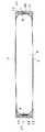
【図1】本発明の一実施例にかかる電池パックの分解斜視図
【図2】図1に示す電池パックの横断面図
【図3】図1に示す電池パックの縦断面図
【図4】図1に示す電池パックの回路図
【図5】薄型電池に端子ホルダを連結した状態を示す一部断面正面図
【図6】薄型電池の電池端面に絶縁リングを積層している状態を示す正面図
【図7】本発明の他の実施例にかかる電池パックの横断面図
【図8】本発明の他の実施例にかかる電池パックの横断面図
【符号の説明】
1…外装ケース 1a…側面ケース部 1b…端部ケース部
1A…第1ケース 1B…第2ケース
2…薄型電池 2A…中央突出部 2B…キャップ部
3…開口部
4…保持溝
5…端子ホルダ
6…絶縁材
7…絶縁シート
8…出力端子
10…凸部電極
12…保護素子
13…電極窓
14…収納室
17…側壁
18…取出用ツメ[0001]
TECHNICAL FIELD OF THE INVENTION
The present invention relates to a battery pack having a thin battery fixed to a case.
[0002]
[Prior art]
A battery pack of a thin battery is mounted on various portable electric devices and used conveniently. In particular, it is an optimal shape for electrical equipment that needs to be designed thin overall, such as a mobile phone. A battery pack of this shape cannot be thinned as long as the thin battery is not thinned, and research has been conducted on how to make the thin battery thinner. At present, polymer batteries are being developed as extremely thin and thin batteries. Since the polymer battery uses an aluminum laminate film for the exterior, the whole can be extremely thin. Further, a thin type lithium ion secondary battery using iron or aluminum for the outer can has been developed.
[0003]
[Problems to be solved by the invention]
Thin batteries such as polymer batteries and lithium ion secondary batteries that are currently being developed are already designed to be quite thin. Furthermore, research is being conducted to make these thin batteries thinner without reducing the charge capacity. Also, for a battery pack having a built-in thin battery, a design for reducing the overall thickness has been made. In particular, it is required that a battery pack to be mounted on a device that needs to be thinner, such as a portable electric device, be designed to be thinner. For this reason, it is extremely important to design the battery pack thin without reducing the charge capacity of the thin battery, and a battery pack that can realize this is required.
[0004]
The present invention has been developed for the purpose of reducing the thickness of a battery pack without reducing the thickness of the thin battery itself with an extremely simple structure.The important object of the present invention is to change the thickness of the thin battery. Another object of the present invention is to provide a battery pack that can reduce the thickness of the entire battery pack to the utmost.
[0005]
[Means for Solving the Problems]
In the battery pack of the present invention, a
[0006]
The
[0007]
The
[0008]
Further, the
[0009]
In the end case portion 1b in which the
[0010]
The surface of the
[0011]
BEST MODE FOR CARRYING OUT THE INVENTION
Hereinafter, embodiments of the present invention will be described with reference to the drawings. However, the following examples illustrate a battery pack for embodying the technical idea of the present invention, and the present invention does not specify a battery pack as follows.
[0012]
Further, in this specification, in order to make it easy to understand the claims, the numbers corresponding to the members shown in the embodiments are referred to as “claims” and “means for solving the problems”. Are added to the members indicated by "." However, the members described in the claims are not limited to the members of the embodiments.
[0013]
The battery pack shown in FIG. 1 includes an
[0014]
The
[0015]
As shown in the cross-sectional views of FIGS. 2 and 3, the
[0016]
In the battery packs of FIGS. 1 and 3, the
[0017]
The
[0018]
In the battery pack, the pair of
[0019]
The
[0020]
The illustrated battery pack includes a
[0021]
The
[0022]
In the illustrated
[0023]
The
[0024]
Further, the insulating
[0025]
The insulating
[0026]
The battery pack can cover the surface of the
[0027]
The insulating
[0028]
However, in the battery pack of the present invention, it is not always necessary to insert the entire periphery of the insulating sheet between the thin battery and the outer case and to sandwich it. As shown in FIG. 8, a part of the edge of the insulating
[0029]
Further, the
[0030]
【The invention's effect】
The battery pack of the present invention has a feature that the thickness of the entire battery pack for housing the thin battery can be reduced to the utmost without reducing the thickness. That is, the battery pack of the present invention is provided with an opening for exposing the front and back surfaces of the thin battery to the outside in an outer case for accommodating the thin battery, and has a rectangular frame shape covering both side surfaces and both end surfaces of the thin battery. It is because it is molded. Since the battery pack of this structure has a structure in which the front and back surfaces of the thin battery are not covered with the outer case as in the related art, the thickness of the entire battery pack is made the same as that of the thin battery while storing the thin battery in the outer case. It is also possible. In particular, in the battery pack of the present invention, the surface of the thin battery is covered with an insulating sheet, and the edge of the insulating sheet is arranged between the thin battery and the outer case, and is sandwiched between the thin battery and the outer case. are doing. Accordingly, there is a feature that the surface of the thin battery can be insulated by the insulating sheet and the insulating sheet can be effectively prevented from peeling off from the edge.
[Brief description of the drawings]
1 is an exploded perspective view of a battery pack according to one embodiment of the present invention; FIG. 2 is a cross-sectional view of the battery pack shown in FIG. 1; FIG. 3 is a longitudinal sectional view of the battery pack shown in FIG. FIG. 5 is a circuit diagram of the battery pack shown in FIG. 1. FIG. 5 is a partial cross-sectional front view showing a state where a terminal holder is connected to a thin battery. FIG. 6 is a front view showing a state where an insulating ring is laminated on a battery end face of the thin battery. FIG. 7 is a cross-sectional view of a battery pack according to another embodiment of the present invention. FIG. 8 is a cross-sectional view of a battery pack according to another embodiment of the present invention.
DESCRIPTION OF
Claims (11)
Translated fromJapanese外装ケース(1)に薄型電池(2)の表裏面を外部に表出させる開口部(3)を設けて、外装ケース(1)を薄型電池(2)の両側面と両端面とをカバーする方形枠形に成形しており、外装ケース(1)の厚さを薄型電池(2)の厚さにほぼ等しく、あるいは外装ケース(1)を薄型電池(2)よりも薄くしており、
さらに、薄型電池(2)の表面を絶縁シート(7)で被覆すると共に、この絶縁シート(7)は縁部を薄型電池(2)と外装ケース(1)との間に配置して、絶縁シート(7)の縁部を薄型電池(2)と外装ケース(1)とで挟着していることを特徴とする電池パック。In a battery pack including a thin battery (2) whose thickness is smaller than the width of the battery, the battery case is mounted on the outer case (1).
An opening (3) for exposing the front and back surfaces of the thin battery (2) to the outside is provided in the outer case (1), and the outer case (1) covers both side surfaces and both end surfaces of the thin battery (2). The thickness of the outer case (1) is substantially equal to the thickness of the thin battery (2), or the outer case (1) is thinner than the thin battery (2);
Further, the surface of the thin battery (2) is covered with an insulating sheet (7), and the edge of the insulating sheet (7) is arranged between the thin battery (2) and the outer case (1) to insulate the battery. A battery pack characterized in that an edge of a sheet (7) is sandwiched between a thin battery (2) and an outer case (1).
Priority Applications (4)
| Application Number | Priority Date | Filing Date | Title |
|---|---|---|---|
| JP2002316184AJP3762737B2 (en) | 2002-10-30 | 2002-10-30 | Battery pack |
| TW092106825ATWI232605B (en) | 2002-04-30 | 2003-03-26 | Battery box |
| US10/424,739US7338733B2 (en) | 2002-04-30 | 2003-04-29 | Battery pack |
| CNB031241271ACN1220288C (en) | 2002-04-30 | 2003-04-29 | Battery assembly |
Applications Claiming Priority (1)
| Application Number | Priority Date | Filing Date | Title |
|---|---|---|---|
| JP2002316184AJP3762737B2 (en) | 2002-10-30 | 2002-10-30 | Battery pack |
Publications (2)
| Publication Number | Publication Date |
|---|---|
| JP2004152603Atrue JP2004152603A (en) | 2004-05-27 |
| JP3762737B2 JP3762737B2 (en) | 2006-04-05 |
Family
ID=32459961
Family Applications (1)
| Application Number | Title | Priority Date | Filing Date |
|---|---|---|---|
| JP2002316184AExpired - Fee RelatedJP3762737B2 (en) | 2002-04-30 | 2002-10-30 | Battery pack |
Country Status (1)
| Country | Link |
|---|---|
| JP (1) | JP3762737B2 (en) |
Cited By (8)
| Publication number | Priority date | Publication date | Assignee | Title |
|---|---|---|---|---|
| JP2006080045A (en)* | 2004-09-13 | 2006-03-23 | Max Co Ltd | Battery pack |
| JP2006236966A (en)* | 2005-01-28 | 2006-09-07 | Sanyo Electric Co Ltd | Battery pack |
| JP2007103284A (en)* | 2005-10-07 | 2007-04-19 | Nec Tokin Corp | Lithium ion battery pack |
| JP2008021507A (en)* | 2006-07-12 | 2008-01-31 | Nec Tokin Corp | Battery pack |
| KR101259944B1 (en) | 2011-08-09 | 2013-05-02 | 주식회사 엘지화학 | Secondary Battery Pack Having PCM Case |
| JP2013225420A (en)* | 2012-04-20 | 2013-10-31 | Sharp Corp | Secondary battery and battery module |
| KR20190138072A (en)* | 2018-06-04 | 2019-12-12 | 에스케이이노베이션 주식회사 | Case for secondary battery and battery module having the same |
| CN117954802A (en)* | 2024-03-26 | 2024-04-30 | 宁德时代新能源科技股份有限公司 | Automatic pasting equipment, battery production system and automatic pasting control method |
- 2002
- 2002-10-30JPJP2002316184Apatent/JP3762737B2/ennot_activeExpired - Fee Related
Cited By (11)
| Publication number | Priority date | Publication date | Assignee | Title |
|---|---|---|---|---|
| JP2006080045A (en)* | 2004-09-13 | 2006-03-23 | Max Co Ltd | Battery pack |
| JP2006236966A (en)* | 2005-01-28 | 2006-09-07 | Sanyo Electric Co Ltd | Battery pack |
| JP2007103284A (en)* | 2005-10-07 | 2007-04-19 | Nec Tokin Corp | Lithium ion battery pack |
| JP2008021507A (en)* | 2006-07-12 | 2008-01-31 | Nec Tokin Corp | Battery pack |
| KR101259944B1 (en) | 2011-08-09 | 2013-05-02 | 주식회사 엘지화학 | Secondary Battery Pack Having PCM Case |
| KR101293591B1 (en) | 2011-08-09 | 2013-08-13 | 주식회사 엘지화학 | Secondary Battery Pack |
| US9793704B2 (en) | 2011-08-09 | 2017-10-17 | Lg Chem, Ltd. | Secondary battery pack |
| JP2013225420A (en)* | 2012-04-20 | 2013-10-31 | Sharp Corp | Secondary battery and battery module |
| KR20190138072A (en)* | 2018-06-04 | 2019-12-12 | 에스케이이노베이션 주식회사 | Case for secondary battery and battery module having the same |
| KR102529975B1 (en) | 2018-06-04 | 2023-05-08 | 에스케이온 주식회사 | Case for secondary battery and battery module having the same |
| CN117954802A (en)* | 2024-03-26 | 2024-04-30 | 宁德时代新能源科技股份有限公司 | Automatic pasting equipment, battery production system and automatic pasting control method |
Also Published As
| Publication number | Publication date |
|---|---|
| JP3762737B2 (en) | 2006-04-05 |
Similar Documents
| Publication | Publication Date | Title |
|---|---|---|
| US7338733B2 (en) | Battery pack | |
| KR100922469B1 (en) | Battery pack | |
| JP5059731B2 (en) | Battery pack | |
| KR100867922B1 (en) | Battery pack | |
| JP6743312B2 (en) | Pouch type secondary battery pack with protection circuit module | |
| EP2043177B1 (en) | Protective circuit board and battery pack using the same | |
| CN100428533C (en) | secondary battery | |
| JP5166462B2 (en) | Battery pack | |
| KR102221780B1 (en) | Battery pack and method for manufcturing the same | |
| KR20180137313A (en) | Battery pack | |
| JP7473367B2 (en) | Battery pack | |
| JP3863856B2 (en) | Battery pack | |
| JP2005100689A (en) | Battery pack | |
| JP3762737B2 (en) | Battery pack | |
| KR100918408B1 (en) | Pouch Type Secondary Battery | |
| JP3806665B2 (en) | Battery pack | |
| JP3762757B2 (en) | Battery pack | |
| JP2004022480A (en) | Battery pack | |
| JP2003017020A (en) | Battery pack | |
| TWI232605B (en) | Battery box | |
| KR20040107868A (en) | Pouched-type lithium secondary battery | |
| JP4318517B2 (en) | Battery pack | |
| JP3272225B2 (en) | Battery pack | |
| JP4663848B2 (en) | Battery pack | |
| KR101313323B1 (en) | Battery Pack Improved in Mounting Structure of Battery Cap onto Battery Cell Case |
Legal Events
| Date | Code | Title | Description |
|---|---|---|---|
| A621 | Written request for application examination | Free format text:JAPANESE INTERMEDIATE CODE: A621 Effective date:20040903 | |
| A977 | Report on retrieval | Free format text:JAPANESE INTERMEDIATE CODE: A971007 Effective date:20051219 | |
| TRDD | Decision of grant or rejection written | ||
| A01 | Written decision to grant a patent or to grant a registration (utility model) | Free format text:JAPANESE INTERMEDIATE CODE: A01 Effective date:20051227 | |
| A61 | First payment of annual fees (during grant procedure) | Free format text:JAPANESE INTERMEDIATE CODE: A61 Effective date:20060113 | |
| FPAY | Renewal fee payment (event date is renewal date of database) | Free format text:PAYMENT UNTIL: 20100120 Year of fee payment:4 | |
| FPAY | Renewal fee payment (event date is renewal date of database) | Free format text:PAYMENT UNTIL: 20100120 Year of fee payment:4 | |
| FPAY | Renewal fee payment (event date is renewal date of database) | Free format text:PAYMENT UNTIL: 20110120 Year of fee payment:5 | |
| FPAY | Renewal fee payment (event date is renewal date of database) | Free format text:PAYMENT UNTIL: 20110120 Year of fee payment:5 | |
| FPAY | Renewal fee payment (event date is renewal date of database) | Free format text:PAYMENT UNTIL: 20120120 Year of fee payment:6 | |
| FPAY | Renewal fee payment (event date is renewal date of database) | Free format text:PAYMENT UNTIL: 20130120 Year of fee payment:7 | |
| LAPS | Cancellation because of no payment of annual fees |