JP2004148998A - Vehicle safety devices - Google Patents
Vehicle safety devicesDownload PDFInfo
- Publication number
- JP2004148998A JP2004148998AJP2002316693AJP2002316693AJP2004148998AJP 2004148998 AJP2004148998 AJP 2004148998AJP 2002316693 AJP2002316693 AJP 2002316693AJP 2002316693 AJP2002316693 AJP 2002316693AJP 2004148998 AJP2004148998 AJP 2004148998A
- Authority
- JP
- Japan
- Prior art keywords
- brake
- safety device
- vehicle
- amount
- increase
- Prior art date
- Legal status (The legal status is an assumption and is not a legal conclusion. Google has not performed a legal analysis and makes no representation as to the accuracy of the status listed.)
- Granted
Links
Images


Classifications
- B—PERFORMING OPERATIONS; TRANSPORTING
- B60—VEHICLES IN GENERAL
- B60T—VEHICLE BRAKE CONTROL SYSTEMS OR PARTS THEREOF; BRAKE CONTROL SYSTEMS OR PARTS THEREOF, IN GENERAL; ARRANGEMENT OF BRAKING ELEMENTS ON VEHICLES IN GENERAL; PORTABLE DEVICES FOR PREVENTING UNWANTED MOVEMENT OF VEHICLES; VEHICLE MODIFICATIONS TO FACILITATE COOLING OF BRAKES
- B60T7/00—Brake-action initiating means
- B60T7/12—Brake-action initiating means for automatic initiation; for initiation not subject to will of driver or passenger
- B60T7/22—Brake-action initiating means for automatic initiation; for initiation not subject to will of driver or passenger initiated by contact of vehicle, e.g. bumper, with an external object, e.g. another vehicle, or by means of contactless obstacle detectors mounted on the vehicle
- B—PERFORMING OPERATIONS; TRANSPORTING
- B60—VEHICLES IN GENERAL
- B60T—VEHICLE BRAKE CONTROL SYSTEMS OR PARTS THEREOF; BRAKE CONTROL SYSTEMS OR PARTS THEREOF, IN GENERAL; ARRANGEMENT OF BRAKING ELEMENTS ON VEHICLES IN GENERAL; PORTABLE DEVICES FOR PREVENTING UNWANTED MOVEMENT OF VEHICLES; VEHICLE MODIFICATIONS TO FACILITATE COOLING OF BRAKES
- B60T8/00—Arrangements for adjusting wheel-braking force to meet varying vehicular or ground-surface conditions, e.g. limiting or varying distribution of braking force
- B60T8/32—Arrangements for adjusting wheel-braking force to meet varying vehicular or ground-surface conditions, e.g. limiting or varying distribution of braking force responsive to a speed condition, e.g. acceleration or deceleration
- B60T8/321—Arrangements for adjusting wheel-braking force to meet varying vehicular or ground-surface conditions, e.g. limiting or varying distribution of braking force responsive to a speed condition, e.g. acceleration or deceleration deceleration
- B60T8/3255—Systems in which the braking action is dependent on brake pedal data
- B60T8/3275—Systems with a braking assistant function, i.e. automatic full braking initiation in dependence of brake pedal velocity
- B—PERFORMING OPERATIONS; TRANSPORTING
- B60—VEHICLES IN GENERAL
- B60T—VEHICLE BRAKE CONTROL SYSTEMS OR PARTS THEREOF; BRAKE CONTROL SYSTEMS OR PARTS THEREOF, IN GENERAL; ARRANGEMENT OF BRAKING ELEMENTS ON VEHICLES IN GENERAL; PORTABLE DEVICES FOR PREVENTING UNWANTED MOVEMENT OF VEHICLES; VEHICLE MODIFICATIONS TO FACILITATE COOLING OF BRAKES
- B60T8/00—Arrangements for adjusting wheel-braking force to meet varying vehicular or ground-surface conditions, e.g. limiting or varying distribution of braking force
- B60T8/32—Arrangements for adjusting wheel-braking force to meet varying vehicular or ground-surface conditions, e.g. limiting or varying distribution of braking force responsive to a speed condition, e.g. acceleration or deceleration
- B60T8/34—Arrangements for adjusting wheel-braking force to meet varying vehicular or ground-surface conditions, e.g. limiting or varying distribution of braking force responsive to a speed condition, e.g. acceleration or deceleration having a fluid pressure regulator responsive to a speed condition
- B60T8/48—Arrangements for adjusting wheel-braking force to meet varying vehicular or ground-surface conditions, e.g. limiting or varying distribution of braking force responsive to a speed condition, e.g. acceleration or deceleration having a fluid pressure regulator responsive to a speed condition connecting the brake actuator to an alternative or additional source of fluid pressure, e.g. traction control systems
- B60T8/4809—Traction control, stability control, using both the wheel brakes and other automatic braking systems
- B60T8/4827—Traction control, stability control, using both the wheel brakes and other automatic braking systems in hydraulic brake systems
- B60T8/4863—Traction control, stability control, using both the wheel brakes and other automatic braking systems in hydraulic brake systems closed systems
- B60T8/4872—Traction control, stability control, using both the wheel brakes and other automatic braking systems in hydraulic brake systems closed systems pump-back systems
- B—PERFORMING OPERATIONS; TRANSPORTING
- B60—VEHICLES IN GENERAL
- B60T—VEHICLE BRAKE CONTROL SYSTEMS OR PARTS THEREOF; BRAKE CONTROL SYSTEMS OR PARTS THEREOF, IN GENERAL; ARRANGEMENT OF BRAKING ELEMENTS ON VEHICLES IN GENERAL; PORTABLE DEVICES FOR PREVENTING UNWANTED MOVEMENT OF VEHICLES; VEHICLE MODIFICATIONS TO FACILITATE COOLING OF BRAKES
- B60T2201/00—Particular use of vehicle brake systems; Special systems using also the brakes; Special software modules within the brake system controller
- B60T2201/02—Active or adaptive cruise control system; Distance control
- B—PERFORMING OPERATIONS; TRANSPORTING
- B60—VEHICLES IN GENERAL
- B60T—VEHICLE BRAKE CONTROL SYSTEMS OR PARTS THEREOF; BRAKE CONTROL SYSTEMS OR PARTS THEREOF, IN GENERAL; ARRANGEMENT OF BRAKING ELEMENTS ON VEHICLES IN GENERAL; PORTABLE DEVICES FOR PREVENTING UNWANTED MOVEMENT OF VEHICLES; VEHICLE MODIFICATIONS TO FACILITATE COOLING OF BRAKES
- B60T2201/00—Particular use of vehicle brake systems; Special systems using also the brakes; Special software modules within the brake system controller
- B60T2201/03—Brake assistants
Landscapes
- Engineering & Computer Science (AREA)
- Transportation (AREA)
- Mechanical Engineering (AREA)
- Physics & Mathematics (AREA)
- Fluid Mechanics (AREA)
- Regulating Braking Force (AREA)
Abstract
Translated fromJapaneseDescription
Translated fromJapanese【0001】
【発明の属する技術分野】
本発明は、車両が衝突する危険性の高い場合などに作動する車両用安全装置に関する。
【0002】
【従来の技術】
従来から、車間距離が所定のしきい値よりも下回った場合に、運転者のブレーキ操作によって発生するブレーキ圧よりも高いブレーキ圧を付与するブレーキアシストシステムを搭載した車両用安全装置が知られている。例えば下記特許文献1では、ブレーキアシストが個々の運転者にとって好適なものとなるように、運転者の運転パターンから、運転者の特性にあった車間距離のしきい値を設定する技術が開示されている。そして、車間距離がこのしきい値以下となり、かつブレーキペダルの操作が所定のストローク速度を超えた場合に、ブレーキアシスト制御が開始される。
【0003】
【特許文献1】
特開平11−124019号公報(11〜12頁、図6)
【0004】
【発明が解決しようとする課題】
特許文献1に開示されているように、運転者の特性に応じて、車間距離のしきい値が好適に設定されたとしても、ブレーキペダルの操作が所定のストローク速度を超えない限り、ブレーキアシスト制御は開始されず、ブレーキアシスト制御の効果が発揮されるのは、運転者がブレーキペダルを所定のストローク速度以上で踏み込み操作をした場合に限られてしまう。
【0005】
この点、ブレーキアシスト制御の開始条件となるストローク速度のしきい値を低く設定して対応することも想定されるが、車間距離が所定のしきい値以下となった際に、例えば運転者がゆっくりとしたブレーキ操作を行っていた場合にも、ブレーキアシスト制御の開始にともなって規定のブレーキアシスト力が付与されて制動力が急増し、ブレーキペダルの操作感とは大きく異なった減速度を運転者が感じることとなってしまう。
【0006】
また、ブレーキ操作と共にステアリング操作によって回避動作を行う場合には、回避操作中に、運転者のブレーキフィーリングとは大きく異なった車両減速度が発生され、この影響で回避操作の操舵感が低下する場合も起こり得る。
【0007】
本発明はこのような課題を解決すべく成されたものであり、その目的は、運転者がブレーキ操作を行った際の実際の操作感が十分に反映された形で安全装置を動作させることで、運転者に違和感を与えることなく安全装置の性能を好適に発揮させることができる車両用安全装置を提供することにある。
【0008】
【課題を解決するための手段】
請求項1にかかる車両用安全装置は、車両の衝突予知度合いに応じて作動する車両用安全装置であって、自車両とこの自車両前方の障害物との相対的な位置関係をもとに、自車両の衝突予知度合いを判定する判定手段と、判定手段の判定結果をもとに、自車両の衝突予知度合いが所定のしきい値を越えた時点における、運転者のブレーキ操作状態量を記憶する記憶手段と、記憶手段で記憶されたブレーキ操作状態量を基準レベルとし、この基準レベルからの増加量に応じて当該安全装置を動作させる動作制御手段とを備えて構成する。
【0009】
動作制御手段は、記憶手段で記憶された基準レベルからの増加量に応じて安全装置の動作制御を行うので、運転者のブレーキ操作状態量の増加傾向が小の場合には安全装置の動作が過剰とならず、また、ブレーキ操作状態量の増加傾向が大の場合には安全装置の性能が十分に発揮されるように動作制御が実施される。なお、衝突予知度合いが所定のしきい値を越えた時点とは、しきい値を越える直前の時点も含むものとする。
【0010】
請求項2にかかる車両用安全装置は、請求項1記載の車両用安全装置において、判定手段によって、所定レベル以上の衝突予知度合いが一定期間継続した場合に、動作制御手段による制御処理を禁止する禁止手段をさらに備えて構成する。
【0011】
このような禁止手段を備えることにより、例えばセンサ故障などにより誤判定が継続して行われた場合に、車両用安全装置の不要な動作が防止される。
【0012】
請求項3にかかる車両用安全装置は、請求項1記載の車両用安全装置において、車速が停止状態を含む所定の低車速の場合、或いは、シフトレバの操作位置が非前進位置の場合の少なくとも一方である場合に、動作制御手段による制御処理を禁止する禁止手段をさらに備えて構成する。
【0013】
車速が低車速或いは停止中の場合には、このような安全装置の動作制御が不要な場合が多いが、相手車両と比較的近い位置関係となり得ることなどから、安全装置が作動し得る状況となる場合も多い。また、シフトレバの操作位置がN(ニュートラル)やP(パーキング)などの非前進位置の場合にも、安全装置の必要性は低い。そこで、このように車速が低車速の場合、シフトレバの操作位置が非前進位置の場合には、安全装置の動作制御が不要であるとみなすこととして、禁止手段によって動作制御手段による制御処理を禁止して、車両用安全装置の不要な作動を防止する。
【0014】
なお、判定手段による判定処理自体が禁止されことで、この判定結果が動作制御手段に与えられない状態となって、結果的に動作制御手段の制御処理が禁止される。従って、禁止手段は、判定手段による判定処理を禁止する場合も含むものとする。
【0015】
請求項4にかかる車両用安全装置は、請求項1記載の車両用安全装置において、動作制御手段は、基準レベルからの増加量に応じて当該安全装置の動作制御を行う際、同じ増加量であっても、衝突予知度合いが高い領域では低い領域に比べて、この増加量がより多い場合の動作制御を実施する。
【0016】
衝突予知度合いが高い領域では、基準レベルからの増加量がより多い場合の動作制御を動作制御手段において実施させることで、安全装置の性能がより多く発揮される。また、衝突予知度合いが低い領域では、安全装置の動作が過剰となることを防止する。
【0017】
請求項5にかかる車両用安全装置は、請求項1記載の車両用安全装置において、動作制御手段は、ブレーキ操作状態量の基準レベルからの増加量が所定の微少増加の範囲内である場合に、この微少増加の範囲を超える所定の増加量に応じた、当該安全装置の動作制御を実施する最小制御手段をさらに備えて構成する。
【0018】
動作制御手段によって、基準レベルからの増加量に応じて安全装置を動作させるため、例えばブレーキ操作状態量の基準レベルからの増加量が小さい場合には、安全装置の動作も僅かなものになってしまい、その性能が十分に発揮されない事態も生じ得る。そこで、衝突予知度合いが所定のしきい値を越えている状況であることも考慮し、ブレーキ操作状態量の基準レベルからの増加量が所定の微少増加の範囲内である場合であっても、最小制御手段によって、この微少増加の範囲を超える所定の増加量に応じた動作制御を実施して、最低限必要となる安全装置の性能を確実に発揮させる。
【0019】
請求項6にかかる車両用安全装置は、請求項5記載の車両用安全装置において、ブレーキ操作状態量の基準レベルからの増加量が所定の微少増加の範囲内で、かつ、ブレーキ操作状態量の基準レベルが所定の緩ブレーキの範囲内である場合には、最小制御手段による動作制御を禁止する禁止手段をさらに備えて構成する。
【0020】
判定手段の判定結果を受けて、自車両の衝突予知度合いが所定のしきい値を越えた時点のブレーキ操作状態量を基準レベルとするが、この基準レベルが緩ブレーキの範囲内の場合には、安全装置を動作させる必要性は低く、判定手段が誤って衝突予知度合いが大であると判定している可能性が大である。このような場合に最小制御手段が働くと、安全装置が作動してしまい、運転者に違和感を与えてしまう。そこで、ブレーキ操作状態量の基準レベルが緩ブレーキの範囲内の場合には、禁止手段によって、最小制御手段による安全装置の動作制御を禁止することで、緩ブレーキ時に安全装置が誤作動した場合の違和感が低減される。
【0021】
請求項7にかかる車両用安全装置は、請求項1乃至6記載の車両用安全装置において、安全装置は、ブレーキアシスト力を発生して、ブレーキ操作に応じたブレーキ力をより増加させるブレーキ制御手段を備えており、動作制御手段は、ブレーキ制御手段の動作制御を実施して、ブレーキ操作状態量の基準レベルからの増加量が多いほど、より大きなブレーキアシスト力を発生させることを特徴とする。
【0022】
安全装置に備えられたブレーキ制御手段を動作制御手段によって動作制御する。これにより、ブレーキ操作状態量の基準レベルからの増加量に応じたブレーキアシスト力が発生されることとなり、運転者のブレーキ操作状態量の増加傾向が小の場合には過剰なブレーキアシスト力が発生されず、また、ブレーキ操作状態量の増加傾向が大の場合にはより大きなブレーキアシスト力が発生される。
【0023】
請求項8にかかる車両用安全装置は、請求項1乃至7記載の車両用安全装置において、運転者のブレーキ操作状態量は、運転者のブレーキ操作力を示す状態量である。
【0024】
ブレーキペダルを踏む力となる踏力、この踏力によって昇圧されるマスターシリンダ圧などは、運転者のブレーキ操作力を示す状態量となり、急制動が必要な状況ほど、換言すれば安全装置を作動させる必要性が高いほど、より大きなブレーキ操作力が作用する。このように運転者のブレーキ操作力をもとに安全装置の動作制御を実施することで、運転者に違和感を与えることなく安全装置の性能を好適に発揮させることができる。
【0025】
【発明の実施の形態】
以下、本発明にかかる車両用安全装置の実施形態について添付図面を参照して説明する。
【0026】
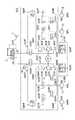
図1に車両用安全装置の全体的な構成を示す。この車両用安全装置は、衝突の危険性が高い場合にブレーキアシスト力を付与する安全装置であって、自車両と自車前方の障害物との相対的な位置関係をもとに自車両の衝突予知レベルを判定する衝突予知判定部100、衝突予知判定部100の判定結果を受けてブレーキアシスト量を設定するブレーキ制御量演算部200、ブレーキ制御量演算部200で演算されたブレーキ制御量に応じたブレーキアシスト力を発生するブレーキアクチュエータ300等を備えて構成している。
【0027】
衝突予知レベルを判定する衝突予知判定部100には、自車両と自車両前方の物体との距離及び相対速度をレーダデータとして検知する距離レーダを備えた障害物センサ10、車両に作用する前後方向の加速度を検知する加速度センサ12、車輪の回転速度を検出する車輪速度センサ14の各検出結果が与えられる。衝突予知判定部100では、障害物センサ10の検出結果から得られる自車両前方の物体との距離情報及び相対速度情報や、加速度センサ12の検出結果から得られる自車両の加減速度情報、車輪速度センサ14の検出結果から得られる車速情報をもとに、自車両前方の物体との距離(車間距離)及び相対速度を求めると共に、T=(距離)/(相対速度)を演算する。そして、この演算結果Tを、図2に示した変換図に従って危険予知レベルαに変換することで、危険予知度合いを判定する。この演算結果Tは「衝突までの時間」に相当する値であって、演算結果Tの値が小さいほど、危険予知レベルαが大となる傾向となっている。なお、Tの演算処理の際に、車速が高いほどTの値がより小さくなるような係数を車速に応じて設定しても良い。また、同一の演算結果Tであっても、高車速ほど危険予知指数αの値が大きくなるような補正処理を実施してもよい。
【0028】
ブレーキ制御量演算部200は、このような衝突予知判定部100の判定結果の他、マスタシリンダ内の液圧を検出するマスタ圧センサ16,ブレーキペダルのストローク量を検出するペダルストロークセンサ18、ブレーキペダルを踏み込む力としての踏力を検出するペダル踏力センサ20の各センサの検出結果や、シフトレバの操作レンジを示すシフト位置センサ、各車輪の回転速度を示す車輪速度センサ14の検出結果が与えられ、これらの入力情報をもとにブレーキアクチュエータ300の動作制御を実行する。
【0029】
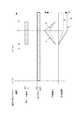
図3にブレーキアクチュエータ300の構成を示す。
【0030】
マスタシリンダ2内には、直列に接続された2個の独立した圧力室2F、2Rを備えており、各圧力室2F、2Rにはそれぞれ作動液が充填されている。ブレーキペダル1が踏み込まれると、マスタシリンダ2内の圧力室2F、2Rの容積が変化して充填された作動液の液圧が上昇する機構となっており、圧力室2Fにおいて、左右の前輪FL、FR側のホイールシリンダ6FL,6FRに作用する液圧が形成され、圧力室2Rにおいて、後輪RL、RR側のホイールシリンダ6RL,6RRに作用する液圧が形成される。
【0031】
圧力室2Fに接続された液圧通路302Fの他端側にはマスターカット弁340Fに接続されている。マスターカット弁340Fは、リニア弁と逆止弁と並列に接続して構成しており、逆止弁は圧力室2Fがホイールシリンダ6FL,6FRに対して高圧の場合、すなわち圧力室2Fからホイールシリンダ6FL,6FR側へ向かう作動液の流通を許容し、その逆方向への作動液の流通を阻止する機能を有している。また、リニア弁は圧力室2Fからホイールシリンダ6FL,6FR側への作動液の流通を阻止すると共に、ホイールシリンダ6FL,6FR側から圧力室2F(又は吸入弁342F)側へ向かう作動液に対しては、この間の流通抵抗となるシール力を、与えられる制御信号(電流信号)に応じてリニアに変化させ得る機能を有している。
【0032】
また、マスターカット弁340Fとホイールシリンダ6FL,6FRとを接続する液圧通路304Fの途中には、オン・オフ信号によって開弁状態と閉弁状態とが切り換わる常時開型の開閉弁(NO弁)320Fを備えており、この開閉弁320Fに対して並列に、ホイールシリンダ6FL,6FR側へ向かう作動液の流通を阻止する逆止弁322Fを設けている。
【0033】
また、モータMによって回転駆動される液圧ポンプ350Fは、ブレーキアシスト力を制御する際の液圧源として機能し、この液圧ポンプ350Fの吐出口は、液圧通路306Fによって、吐出口への逆流を阻止する逆止弁352F、ダンパ室354Fを経由して、マスターカット弁340Fの下流側に接続されている。これにより、液圧ポンプ350Fから吐出された作動液は、液圧通路306F及び304Fを経由してホイールシリンダ6FL,6FRに供給可能となっている。
【0034】
この液圧ポンプ350Fの吸込口側は、液圧通路308Fを介してリザーバ360Fに接続されており、この液圧通路308Fには、吸込方向とは逆方向の作動液の流れを阻止する逆止弁356F、358Fを設けている。
【0035】
また、開閉弁320Fとホイールシリンダ6FL,6FRとの間の液圧通路304Fは、液圧通路310Fを介してリザーバ360Fに接続されており、液圧通路310Fの途中には、オン・オフ信号によって開弁状態と閉弁状態とが切り換わる常時閉型の開閉弁(NC弁)330Fを備えている。
【0036】
さらに、逆止弁356F、358Fの間の液圧通路308Fと、液圧通路302Fとは、液圧通路312Fによって接続されており、液圧通路312Fの途中には、オン・オフ信号によって開弁状態と閉弁状態とが切り換わる吸入弁342Fを備えており、吸入弁342Fの開閉を切り換え制御或いはDuty制御することで、液圧ポンプ350Fへの吸い込み量が制御でき、これによって液圧ポンプ350Fからの作動液の吐出量が調整可能である。
【0037】
これに対し、後輪RL、RR側の液圧伝達系となる、圧力室2Rとホイールシリンダ6RL,6RRとの間も、前述した前輪FR、FL側と同様な構成となっている。図3中、前輪FR、FL側の各構成要素に付された参照符号の「F」を「R」に置き換えて、対応する後輪RL、RR側の液圧伝達系の各構成要素を示すこととし、説明は省略する。
【0038】
なお、ブレーキペダル1には、ブレーキベダル1が踏み込まれたストロークを検出するペダルストロークセンサ18と、ブレーキペダル1を踏み込む力となる踏力を検出するペダル踏力センサ20とを備えており、また、マスタリシンダ2で発生される油圧を検出するマスタ圧センサ16を、液圧通路302Rに対して設けている。
【0039】
このように、ポンプや各種の弁装置などによって構成されるブレーキアクチュエータ300は、ブレーキ制御量演算部200によって動作制御が実施される。ブレーキ制御量演算部200は、緊急制動時により大きな制動力を発生させるブレーキアシスト制御、前方車両との間に所定の車間距離を確保する車間距離制御などの各制御を実行し、各種の制御処理に応じて、ブレーキアクチュエータ100の動作制御を行う。
【0040】
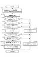
次に、ブレーキ制御量演算部200で実施するブレーキアクチュエータ300の制御処理のうち、ブレーキアシスト制御処理について、図4のフローチャートに沿って説明する。
【0041】
イグニションスイッチのON操作によって起動した後、まず、ステップ(以下、「ステップ」を「S」と記す)102に進み、各車輪FL,FR,RL,RRの車輪速度WV、シフトレバのシフト位置情報、マスタ圧P、衝突予知判定部100で判定された衝突予知レベルαを読み込み、続くS104では、各車輪のFL,FR,RL,RRの車輪速度WVをもとに、自車両の車両速度Vを演算する。
【0042】
続くS106では、S104で演算した車両速度Vが所定の低車速を示すしきい値Vthよりも小であるかを判断し、続くS108では、シフトレバの操作位置が、P(パーキング)レンジ、N(ニュートラル)レンジ、R(リバース)レンジのいずれかであるか、すなわちシフトレバが非前進位置にあるかを判断する。
【0043】
ここでS106及びS108の判断処理について説明する。車両速度Vが極く低車速で走行する状況下では、ブレーキアシスト制御の必要性は低い。さらに、衝突予知判定がレーダ装置を用いた障害物センサによって他車両(自車両前方の障害物)との相対的な位置関係をもとに判断するため、特に、自車両が交差点などで停止中(車両速度V=0)の場合であっても、右折する他車両が接近した場合に衝突予知度レベルが増加して、ブレーキアクチュエータ300が不必要に動作する場合も起こり得る。また、自車両がけん引される場合には、通常、シフトレバの操作位置がN(ニュートラル)位置に操作されるが、けん引する前車との車間距離が比較的近い状況となって衝突予知度レベルが増加する場合が生じ得る。また、シフトレバをP(パーキング)位置に操作して、坂路(特に上り勾配)手前で駐車した際などには、坂路を自車両前方の障害物として認識する場合がある。また、シフトレバをR(リバース)位置に操作して車両を後退させる場合には、通常、極く低車速で走行するため、ブレーキアシスト制御の必要性は低い。
【0044】
このようにS106及びS108の判断処理は、実質的に、ブレーキアシスト制御が実行されることを禁止する禁止条件を判断しており、これらS106及びS108で、いずれかが「Yes」と判断された場合には、S122に進んで、液圧ポンプ350F、350Rを駆動するモータMをOFF状態とし、S124に進み、S102で読み込んだマスタ圧Pの値を、ブレーキアシスト力を設定する際の基準となる加圧量基準値Psとして記憶させた後、今回のルーチンを終了する。
【0045】
なお、この状況では、各弁装置に対して動作制御が実行されていないため、各弁装置は初期状態を維持しており、吸入弁342F、342Rが閉弁状態、開閉弁320F、320Rは開弁状態、開閉弁330F、330Rは閉弁状態であり、ブレーキペダル1の踏み込み操作によって発生した、マスタシリンダ2の各圧力室2F、2Rの液圧が、ホイールシリンダ6FL,6FR、6RL、6RRに与えられる。
【0046】
一方、S106及びS108の判断処理で、ともに「No」と判断された場合には、S110に進み、S102で読み込んだ衝突予知レベルαの値が比較的に低い予知レベルα1より大であるかをさらに判断する。そして、衝突予知レベルαの値が比較的に低い予知レベルα1以下の場合には(S110で「No」)、前述したS122以降の処理に移るが、衝突予知レベルαがα1より大である場合には(S110で「Yes」)、S112に進んで、液圧ポンプ350F、350Rを駆動するモータMをON状態に制御して、ブレーキアシスト制御の開始に備える。実際に制御が開始されるタイミングでモータMをONさせると、制御上予定されたモータMの回転数に到達するまでに所定の時間が費やされるが、このように衝突予知レベルαが比較的低いα1以上となった時点で、予めモータMをON状態に制御しておくことで、制御開始時点で所定のモータ回転数が得られるため、液圧制御の応答性が向上する。
【0047】
S112でモータMをONさせた後、S114に進み、S102で読み込まれたマスタ圧Pの値が、所定の大きな液圧Pmaxより小であるかを判断し、「No」の場合には、ブレーキアシスト制御を開始する以前に、運転者がブレーキペダル1を十分に踏み込んで大きな液圧を発生させている状況であり、このような場合には、ブレーキアシスト制御は不要であり、S124以降の処理に進み、ブレーキアシスト制御を実行せず今回のルーチンを終了する。
【0048】
S114で「Yes」、すなわち、S102で読み込まれたマスタ圧Pの値が液圧Pmaxより小である場合には、S116に進んで、衝突予知レベルαの値が、α1よりも大きなα2を越えているかを判断し、衝突予知レベルαがα2以下の場合には(S116で「No」)、ブレーキアシスト制御の開始条件を満たしていないものとみなしてS124に進み、ブレーキアシスト制御を実行することなく今回のルーチンを終了する。
【0049】
そして衝突予知レベルαがα2を越えている場合には(S116で「Yes」)、S118に進んで、ブレーキアシスト力に対応する制動増加量ΔPをΔP=(P−Ps)*Kとして設定する。ここで「K」は所定の増加量係数(K>0)、「P」はS102で読み込んだマスタ圧、「Ps」は前回以前のルーチンにおけるS124で設定した加圧量基準値である。
【0050】
この後、S120に進み、S118で設定した制動増加量ΔPをもとに、運転者のブレーキ操作によって発生する液圧よりもΔPだけ高い液圧が、ホイールシリンダ6FL,6FR、6RL、6RRに作用するように、ブレーキアクチュエータ300の動作制御を実施する。この際、吸入弁342F、342Rを開弁状態に或いは開閉状態をduty駆動すると共にモータMをduty駆動し、またマスターカット弁340Fに備えられたリニア弁の開弁状態の動作制御を実施する。
【0051】
このような処理を繰り返し実行することで、ブレーキアシスト制御が開始される直前のマスタ圧P(加圧量基準値Ps)を基準として、この加圧量基準値Psからのマスタ圧Pの増加量偏差に応じたブレーキアシスト力が付与されることとなる。このため、運転者のブレーキ操作量の増加傾向が小の場合には過剰なブレーキアシスト力が発生されず、また、ブレーキ操作量の増加傾向が大の場合にはより大きなブレーキアシスト力を発生させることができる。
【0052】
なお、図4のブローチャートでは省略したが、S120においてブレーキアシスト制御が開始された後は、マスタ圧Pが加圧量基準値Ps以上の場合にブレーキアシスト制御が継続され、マスタ圧Pが加圧量基準値Psより低下した場合には、ブレーキアシスト制御は終了する。
【0053】
また、図4のブローチャートでは省略したが、S120においてブレーキアシスト制御が開始された後に、衝突予知レベルαがα2以下に低下した場合、すなわちブレーキアシスト制御中にS116で「No」と判断された場合には、ブレーキアシスト制御を終了させるべく、ホイールシリンダ6FL,6FR、6RL、6RRに作用する液圧が、運転者のブレーキ操作に応じた液圧まで、所定の減圧勾配で低下するように、ホイールシリンダ6FL,6FR、6RL、6RRに作用する液圧を低下させる減圧制御処理を実行することが望ましい。この場合の制御例としては、吸入弁342F、342Rを閉弁状態に制御すると共に、マスターカット弁340Fに備えられたリニア弁の弁開度を所定の勾配で徐々に開弁させることで、ホイールシリンダ6FL,6FR、6RL、6RRに作用する液圧が運転者のブレーキ操作に応じた液圧まで徐々に低下する。
【0054】
また、このように図4のブローチャートでは、S120においてブレーキアシスト制御が開始された後に、衝突予知レベルαがα2以下に低下した場合には、ブレーキアシスト制御が終了する場合について例示した。これは、前方車両との間に所定の車間距離を確保する車間制御の場合に好適な実施形態であり、この例に限定するものではない。衝突回避などの、より緊急性の高いプリクラッシュブレーキ制御などでは、S120においてブレーキアシスト制御が開始された後は、自車両が停止(車両速度V=0)するまで、ブレーキアシスト制御を継続する手法を採用することも可能である。
【0055】
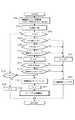
この制御例を図5のフローチャートに示す。
【0056】
図5のフローチャートでは、図4のフローチャートにおける処理ステップを全て採用しており、新たに加わった処理ステップをS200番台のステップ数を付して示している。
【0057】
追加ステップについて説明すると、S104で車両速度Vを演算した後、S200に進み、フラグFの値がF=0、すなわちブレーキアシスト制御の開始前であるかを判断する。このフラグFは、S118に続くS202において、フラグFをF=1に設定して、ブレーキアシスト制御が実施中であることを示すフラグである。
【0058】
S200の判断において、ブレーキアシスト制御の開始前では(S200で「Yes」)、S106以降の処理に進むが、ブレーキアシスト制御が開始された後は(S200で「No」)、S204に進んで、S104で演算された車両速度VがV=0であるかを判断し、車両が停止前の場合には(S204で「No」)、S118以降の処理に移る。このようなルーチンを繰り返すうち、車両が停止するとS204で「Yes」と判断されてS206に進み、フラグFをF=0にリセットしてこのルーチンを終了する。
【0059】
このような制御処理を実行することにより、S120においてブレーキアシスト制御が開始された後は、自車両が停止(車両速度V=0)するまでブレーキアシスト制御を継続することが可能となる。なお、図5のフローチャートでは省略したが、終了処理となるS206では、前述したようにホイールシリンダ6FL,6FR、6RL、6RRに作用する液圧を徐々に低下させる減圧制御処理を実行することが望ましい。
【0060】
ここで、他の実施形態につき、図6に示すフローチャートに沿って説明する。図6のフローチャートでは、衝突予知レベルαが所定時間継続して出力された場合には、センサ故障などによって危険予知判定が誤作動しているものとして、ブレーキアシスト制御を禁止する場合の処理を示す。
【0061】
このフローチャートはイグニションスイッチのON操作によって起動する。起動後S302に進み、衝突予知判定部100の判定結果となる衝突予知レベルαを読み込み、続くS304で、S302で読み込んだ衝突予知レベルαの値がα>0であるかを判断する。その結果、衝突予知レベルαがα=0の場合には(S304で「No」)、S306に進み、衝突予知レベルα>0となる時間を計時するタイマのカウント値Tの値をT=0にリセットして、再びS302以降の処理を開始する。
【0062】
一方、S304で衝突予知レベルαがα>0の場合には(S304で「Yes」)、S308に進み、タイマのカウント値Tの値をT+1にカウントアップした後、S310に進む。S310では、タイマのカウント値Tが所定のしきい値Tthを越えたかを判断し、「No」の場合には今回のルーチンを終了するが、S310で「Yes」、すなわちタイマのカウント値Tが所定のしきい値Tthを越えると、衝突予知レベルαがα>0である時間がしきい値Tthを越えて長大した状況である。このような状況では、障害物センサ10がノイズを検出し続ける誤検出、検出信号にノイズが含まれるなどの通信障害、センサ自体或いは衝突予知判定部100自体が故障して誤った衝突判断が出力されている場合であるとみなし、ブレーキアシスト制御自体を禁止すべく、S312に進む。
【0063】
S312では、先の図5で説明したようにフラグFの値がF=1に設定されているか等によって、ブレーキアシスト制御が実施中、すなわち制動増加量ΔPが設定中であるかを判断し、設定中である場合には(S312で「Yes」)、ブレーキアシスト制御が終了するまで、この判断を繰り返し実行する。そして、ブレーキアシスト制御が一旦終了すると、S312で「Yes」と判断されてS314に進み、警告灯を点灯させてブレーキアシスト制御システムに故障が発生したことを運転者に知らせる。そしてS316に進んで、図4或いは図5で示したブレーキアシスト制御処理を禁止して、この図6の判定ルーチンを終了する。
【0064】
図6のフローチャートでは、衝突予知レベルαがα>0である時間を計時したが、このほかにも例えばα>α1である時間を計時してもよく、計時対象となるαのしきい値は適宜設定することができる。
【0065】
また、図6のフローチャートでは、タイマのカウント値Tがしきい値Tthを越えた場合に、ブレーキアシスト制御を禁止する場合を例示したが、このほかにも、先の図5でも示したように、車両速度Vが所定の低車速Vthより小の場合や、シフトレバの操作レンジがP、N、Rレンジのいずれかとなる非前進位置の場合にも、ブレーキアシスト制御を禁止するように判定しても良い。
【0066】
また、図6のフローチャートではブレーキアシスト制御処理を禁止する場合を例示したが、衝突予知判定部100による判定処理自体を禁止することで、ブレーキ制御量演算部200には衝突予知レベルα=0が強制的に与えられる状況となって、結果的にブレーキアシスト制御が禁止される。従って、S316では、衝突予知判定部100による判定処理を禁止する手法を採用することも可能である。
【0067】
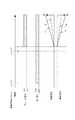
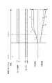
ここで、図4のフローチャートに示すブレーキアシスト制御の作動状況として、代表的な作動状況を図7〜図10に模式的に示す。
【0068】
まず図7では、時間t1において衝突予知レベルαがα=α1となると、モータMがON状態となる。そして時間t2で衝突予知レベルαがα=α2となると、ブレーキアシスト制御の実行条件が整うこととなるが、未だ、実際にブレーキペダル1が踏み込まれていない状況であるため、ホイールシリンダの作動液圧に変化はない。そして、時刻t3でブレーキ操作が行われるとブレーキアシスト制御が開始され、時刻t3における作動液圧を加圧量基準値Ps(この場合Ps=0)とし、この加圧量基準値Psからの増加偏差分に応じたブレーキアシスト力が付与され、矢印aで示すように作動液圧が上昇する。なお、矢印bはブレーキアシスト制御が実施されない場合の作動液圧の推移を示し、また、矢印a’、b’はそれぞれ、矢印a,bに示すように作動液圧が推移した場合における、車両速度の変化状況を示している。
【0069】
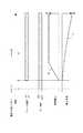
また、図8に示すように、時刻t1以降で時刻t2前となる時刻t4においてブレーキ操作が開始された場合には、時刻t4〜t2の間では衝突予知レベルαがα1<α<α2であるため、ブレーキアシスト制御が実施されずに矢印cで示すように、ブレーキ操作に応じた作動液圧がホイールシリンダ内に作用する。そして、時刻t2で衝突予知レベルαがα=α2となると、ブレーキアシスト制御が開始されるが、この状況では時刻t2における作動液圧を加圧量基準値Psとし、この加圧量基準値Psからの増加偏差分に応じたブレーキアシスト力が付与され、矢印dで示すように作動液圧が上昇する。なお、矢印eはブレーキアシスト制御が実施されない場合の作動液圧の推移を示し、また、矢印d’、e’はそれぞれ、矢印d,eに示すように作動液圧が推移した場合における、車両速度の変化状況を示している。
【0070】
また、図9に示すように、時刻t2以降となる時刻t5でブレーキペダル1を踏み込むとブレーキアシスト制御が開始され、この場合時刻t5における作動液圧を加圧量基準値Psとし、この加圧量基準値Psからの増加偏差分に応じたブレーキアシスト力が付与され、矢印fで示すように作動液圧が上昇する。そして時刻t6で運転者がブレーキペダル1の踏み込みを緩めると、時刻t6〜t7の間は、加圧量基準値Psからの偏差分が徐々に減少するため、これに応じてブレーキアシスト力も徐々に低下し、時刻t7で運転者がブレーキペダル1から足を離した時点で、ブレーキアシスト制御は終了する。なお、矢印gはブレーキアシスト制御が実施されない場合の作動液圧の推移を示し、また、矢印f’、g’はそれぞれ、矢印f,gに示すように作動液圧が推移した場合における、車両速度の変化状況を示している。
【0071】
また、図10に示すように、時刻t8でブレーキ操作が開始され、衝突予知レベルαがα=α2となる時刻t2以前に、十分なブレーキ操作量があって作動液圧(ここではマスタ圧P)が十分に高い場合には、ブレーキアシスト制御は実施されず、ブレーキ操作によって発生する作動液圧が各車輪のホイールシリンダに供給され、矢印hで示すように作動液圧が推移する。なお、矢印h’は、矢印hに示すように作動液圧が推移した場合における、車両速度の変化状況を示している。
【0072】
次に、さらに他の実施形態について説明する。
【0073】
図4などでS118として示した処理ステップでは、制動増加量ΔPをΔP=(P−Ps)*Kとして設定する場合について説明したが、この増加量係数K(K>0)の値を、衝突予知レベルαの値に応じて可変設定することも可能である。
【0074】
この場合の制御処理を図11に示す。図11に示すフローチャートは、図4のフローチャートで示した全処理ステップを採用すると共に、S130を新たに追加している。
【0075】
前述したようにS116において、衝突予知レベルαの値が、ブレーキアシスト制御の開始条件となるα2を越えているかを判断する。越えている場合には(S116で「Yes」)S130に進み、図12に示すグラフをもとに、S102で読み込んだ衝突予知レベルαの値に応じて増加量係数Kの値を設定する。図12では、衝突予知レベルαがα=α2から増加するに連れて増加量係数Kの値が次第に増加する傾向となっている。従って、衝突予知レベルαがα=α2よりも十分に高い領域では、低い領域に比べてより大きな増加量係数Kの値が設定される。このようにS130で衝突予知レベルαに応じた増加量係数Kの値を設定した後、S118に進んで、制動増加量ΔPをΔP=(P−Ps)*Kとして設定する。
【0076】
従って、衝突予知レベルαがα=α2に比べて大きい状況では、制動増加量ΔPの値がより大きな値に設定されることとなり、衝突予知レベルαの値が大である場合には、より大きなブレーキアシスト力を発生させることが可能となる。
【0077】
また他の実施形態について説明する。
【0078】
図4などに示したブレーキアシスト制御では、マスタ圧Pが基準レベルPsから増加した分に応じたブレーキアシスト力を発生させており、この点、例えば衝突予知レベルαがα=α2を越えた時点からのマスタ圧Pの増加分が小さい場合には、発生するブレーキアシスト力も小さな力となってしまう。そこで、衝突予知度レベルαの値が、制御開始のしきい値となるα=α2を越えている状況であることも考慮し、運転者のブレーキ操作に対応するマスタ圧Pの上昇が、基準レベルPsから微少増加の範囲内である場合であっても、この微少増加に対応するブレーキアシスト力を越えるような、所定のブレーキアシスト力(標準ブレーキアシスト力)を最低限発生させことも可能である。
【0079】
このようなブレーキアシスト制御の制御処理例を図13に示す。図13に示すフローチャートは、図4のフローチャートで示した全処理ステップを採用すると共に、S140、S142を新たに追加している。
【0080】
前述したようにS118において、制動増加量ΔPをΔP=(P−Ps)*Kとして設定した後、S140に進み、S118で設定した制動増加量ΔPが、予め規定した制動増加量ΔPの下限値となる、最低制動増加量ΔPmin以上であるかを判断する。この最低制動増加量ΔPminは、ブレーキアシスト制御を開始する際に、最低限付与すべき「標準ブレーキアシスト力」を発生させるための制動増加量として予め規定した値である。
【0081】
そこで、S118で設定した制動増加量ΔPが、この最低制動増加量ΔPmin以上である場合には(S140で「Yes」)、S120に進んで、前述したようにS118で設定した制動増加量ΔPをもとに、ブレーキアクチュエータ300の動作制御を実施する。
【0082】
これに対し、S118で設定した制動増加量ΔPが、この最低制動増加量ΔPminよりも小の場合には(S140で「No」)、S142に進み、S118で設定した制動増加量ΔPを、このΔPよりも大となる最低制動増加量ΔPminに更新して、S120に進む。
【0083】
従って、S118で設定した制動増加量ΔPが、この最低制動増加量ΔPminよりも小である期間では、最低制動増加量ΔPminに対応した一定のブレーキアシスト力が常に発生され、S118で設定した制動増加量ΔPが最低制動増加量ΔPmin以上となると、S118で設定した制動増加量ΔP、すなわち運転者のブレーキ操作に対応した、より大きなブレーキアシスト力が発生されることとなる。
【0084】
このような制御処理を実施した場合の液圧の推移状況を図14に示す。時間t9で衝突予知レベルαがα=α2となった場合、このときのマスタ圧Pが加圧量基準値Psである。そして、一点鎖線L1で示すように、その後のマスタ圧Pの増加傾向が低いような微少増加の範囲内の場合には、S118で設定した制動増加量ΔPをそのまま適用してブレーキアシスト力を発生させると、時間t9〜t10の間に点線L2で示すように、ホイールシリンダ圧の増加傾向も緩慢となり、この間も、ブレーキアシストの効果をより多く発揮させることが望ましい。
【0085】
そこで、S118で設定した制動増加量ΔPがこの最低制動増加量ΔPminよりも小である期間では、S118で設定した制動増加量ΔPを、より大きな値に規定された最低制動増加量ΔPminに更新することで(S142)、実際には時間t9〜t10の間にも、マスタ圧Pに対し、最低制動増加量ΔPminに対応したブレーキアシスト力が付与されることとなる(線分L3)。そして時間t10で、S118で設定した制動増加量ΔPが最低制動増加量ΔPmin以上となると、時間t10以降では、S118で設定した制動増加量ΔPをもとに、運転者のブレーキ操作に応じた、より大きなブレーキアシスト力が発生されることとなる(線分L4)。
【0086】
なお、図13のフローチャートでは、S116、S118の処理を経た後にS140に進む場合を例示したが、このS116とS118との間に、S130(図11)を実行することにより、増加量係数Kの値を衝突予知レベルαに応じて設定しても良い。
【0087】
さらに他の実施形態を図15に示す。
【0088】
図15のフローチャートでは、図13のフローチャートにおける、S140とS142との間にS150を追加している。このS150に進む状況としては、S118で設定した制動増加量ΔPが低制動増加量ΔPminよりも小である状況であり(S140で「No」)、先に説明した図13では、S142に進んで、制動増加量ΔPを最低制動増加量ΔPminに更新し、S120に進んでブレーキアクチュエータ300の動作制御を実施する。
【0089】
しかし、ブレーキアシスト制御を開始する直前のマスタ圧Pを示す加圧量基準値Psが、所定の低液圧以下の、いわゆる緩ブレーキの場合には、運転者がさほど大きな急制動を必要としていない状況であるみなすことができ、誤検出などの何らかの原因によって、衝突予知判定部100が誤って衝突予知度合いαが大であると判定している可能性が大きい。このような場合に、前述したような標準ブレーキアシスト力が発生されると、制動力が急増して運転者に違和感を与えてしまう。
【0090】
そこで、S140で「No」、すなわちS118で設定した制動増加量ΔPが低制動増加量ΔPminよりも小である状況では、まずS150に進んで、ブレーキアシスト制御を開始する直前のマスタ圧Pを示す加圧量基準値Psが、所定の低液圧しきい値Psminよりも大であるかを判断する。そして、加圧量基準値Psが低液圧しきい値Psminより大である場合には(S150で「Yes」)、前述したようにS142に進んで、制動増加量ΔPを最低制動増加量ΔPminに更新するが、加圧量基準値Psが低液圧しきい値Psmin以下の緩ブレーキの範囲である場合には(S150で「No」)、そのままS120に進むこととし、これによりS118で設定した制動増加量ΔPに基づいたブレーキアシスト力を発生させる。この際に発生するブレーキアシスト力は、最低限付与すべき「標準ブレーキアシスト力」よりも小さなアシスト力であって、運転者のブレーキ操作に応じた、小さなブレーキアシスト力が付与されることとなる。従って、S150は、緩ブレーキの際に、標準ブレーキアシスト力の発生処理を禁止させる禁止処理として機能しており、これにより、緩ブレーキ時に標準ブレーキアシスト力が付与される場合に、運転者が感じる違和感を十分に低減させることができる。
【0091】
以上説明した各実施形態では、車両用安全装置として、衝突の危険度合いが高い場合、所定の車間距離を確保する場合などにブレーキアシスト力を発生するタイプの安全装置を例に説明したが、このようにブレーキアシスト力を発生する安全装置に限定するものではない。例えば、衝突予測時にシートベルトをモータなどによって巻き取って、所定の強い張力を予めシートベルトに与えて人員を保護するプリテンショナーベルトに対しても適用することができる。この場合、シートベルトに与える張力を、加圧量基準値Psからのマスタ圧Pの増加量偏差に応じて増加させる等、前述した各実施形態で制御処理を、シートベルトを巻き取るモータの動作制御として実施すればよい。
【0092】
【発明の効果】
以上説明したように、請求項1にかかる車両用安全装置によれば、衝突予知度合いがしきい値を越えた時点における、運転者のブレーキ操作状態量を記憶する記憶手段と、このブレーキ操作状態量からの増加量に応じて当該安全装置を作動させる作動制御手段とを備える構成を採用した。これにより、運転者のブレーキ操作状態量の増加傾向が小の場合には、安全装置の動作が過剰とならず、また、ブレーキ操作状態量の増加傾向が大の場合には安全装置の性能が十分に発揮されるように動作制御が実施することができる。従って、運転者がブレーキ操作を行った際の実際の操作感を十分に反映させた形で安全装置の動作制御を行うことが可能となり、運転者に違和感を与えることなく安全装置の性能を好適に発揮させることが可能となる。
【0093】
請求項2にかかる車両用安全装置は、所定レベル以上の衝突予知度合いが一定期間継続した場合に、動作制御手段による制御処理を禁止する禁止手段をさらに備えるので、例えばセンサ故障などにより誤判定が継続して行われた場合に、車両用安全装置の不要な動作を防止することが可能となる。
【0094】
請求項3にかかる車両用安全装置は、車速が低車速の場合や、シフトレバの操作位置が非前進位置の場合に、動作制御手段による制御処理を禁止する禁止手段をさらに備えるので、安全装置の作動が実質的に不要である場合に、安全装置が誤作動することを防止することができる。
【0095】
請求項4にかかる車両用安全装置は、動作制御手段によって、基準レベルからの増加量が同じ増加量であっても、衝突予知度合いが高い領域では低い領域に比べて、この増加量がより多い場合の動作制御を実施させることとした。これにより、衝突予知度合いが高い領域では安全装置の性能がより多く発揮させ、衝突予知度合いが低い領域では安全装置の動作が過剰となることを防止することが可能となる。
【0096】
請求項5にかかる車両用安全装置は、ブレーキ操作状態量の基準レベルからの増加量が所定の微少増加の範囲内である場合であっても、この微少増加の範囲を超える所定の増加量に応じた動作制御を実施する最小制御手段を備える構成を採用した。これにより、衝突予知度合いがしきい値を越えた時点からの、ブレーキ操作状態量の増加分が小さい場合にも、最低限必要となる安全装置の性能を確実に発揮させることが可能となる。
【0097】
請求項6にかかる車両用安全装置は、基準レベルからの増加量が微少増加の範囲内で、かつ、この基準レベルが所定の緩ブレーキの範囲内である場合には、最小制御手段による動作制御を禁止する禁止手段を備える構成を採用した。このため、緩ブレーキ時に安全装置が誤作動した場合に運転者が受ける違和感を低減させることが可能となる。
【0098】
請求項7にかかる車両用安全装置は、この安全装置はブレーキアシスト力を発生するブレーキ制御手段を備え、動作制御手段はこのブレーキ制御手段の動作制御を実施して、ブレーキ操作状態量の基準レベルからの増加量が多いほど、より大きなブレーキアシスト力を発生させることとした。これにより、運転者のブレーキ操作状態量の増加傾向が小の場合には過剰なブレーキアシスト力を発生することがなく、また、ブレーキ操作状態量の増加傾向が大の場合にはより大きなブレーキアシスト力を発生させることができるため、ブレーキ操作を行った際の実際の操作感が十分に反映された形で、ブレーキアシスト力を発生させることが可能となる。
【0099】
請求項8にかかる車両用安全装置は、運転者のブレーキ操作状態量を、運転者のブレーキ操作力を示す状態量としたので、運転者のブレーキ操作力の大小を、安全装置の性能を発揮させる程度の大小として把握し、これをもとに安全装置の動作制御を実施するため、運転者の実際の操作感を十分に反映させ、運転者に違和感を与えることなく安全装置の性能を好適に発揮させることが可能となる。
【図面の簡単な説明】
【図1】実施形態にかかる車両用安全装置の構成を示すブロック図である。
【図2】演算結果Tと衝突予知レベルαとの関係を規定した変換図である。
【図3】ブレーキアクチュエータの構成を示す液圧系統図である。
【図4】ブレーキアシスト制御処理を示すフローチャートである。
【図5】他の実施形態にかかるブレーキアシスト制御処理を示すフローチャートである。
【図6】ブレーキアシスト制御の禁止処理を示すフローチャートである。
【図7】ブレーキアシスト制御の作動状況を模式的に示す説明図である。
【図8】ブレーキアシスト制御の作動状況を模式的に示す説明図である。
【図9】ブレーキアシスト制御の作動状況を模式的に示す説明図である。
【図10】ブレーキアシスト制御の作動状況を模式的に示す説明図である。
【図11】他の実施形態にかかるブレーキアシスト制御処理を示すフローチャートである。
【図12】衝突予知レベルと増加量係数Kとの関係を規定したグラフである。
【図13】他の実施形態にかかるブレーキアシスト制御処理を示すフローチャートである。
【図14】図14に示す制御処理を実施した場合における、液圧の推移状況を示すチャートである。
【図15】他の実施形態にかかるブレーキアシスト制御処理を示すフローチャートである。
【符号の説明】
1…ブレーキペダル、2…マスタシリンダ、2F、2R…圧力室、
6FL、6FR、6RL、6RR…ホイールシリンダ、
340F、340R…マスターカット弁、
342F、342R…吸入弁[0001]
TECHNICAL FIELD OF THE INVENTION
The present invention relates to a vehicle safety device that operates when a vehicle has a high risk of collision.
[0002]
[Prior art]
Conventionally, there has been known a vehicle safety device equipped with a brake assist system that applies a brake pressure higher than a brake pressure generated by a driver's brake operation when an inter-vehicle distance falls below a predetermined threshold value. I have. For example,
[0003]
[Patent Document 1]
Japanese Patent Application Laid-Open No. H11-1224019 (pages 11 to 12, FIG. 6)
[0004]
[Problems to be solved by the invention]
As disclosed in
[0005]
In this regard, it is conceivable that the threshold value of the stroke speed, which is the start condition of the brake assist control, is set to a low value to cope with the problem. Even when a slow brake operation is being performed, the specified brake assist force is applied at the start of the brake assist control, the braking force increases rapidly, and the deceleration greatly differs from the brake pedal operation feeling People will feel it.
[0006]
In addition, when the avoidance operation is performed by the steering operation together with the brake operation, the vehicle deceleration greatly differs from the driver's brake feeling during the avoidance operation, and the steering feeling of the avoidance operation is reduced due to this effect. It can happen.
[0007]
The present invention has been made to solve such a problem, and an object of the present invention is to operate a safety device in a form sufficiently reflecting an actual operation feeling when a driver performs a brake operation. Accordingly, it is an object of the present invention to provide a vehicle safety device capable of suitably exhibiting the performance of the safety device without giving a driver an uncomfortable feeling.
[0008]
[Means for Solving the Problems]
A vehicle safety device according to
[0009]
The operation control means controls the operation of the safety device in accordance with the amount of increase from the reference level stored in the storage means. If the amount of brake operation does not become excessive and the tendency to increase the amount of brake operation is large, operation control is performed so that the performance of the safety device is sufficiently exhibited. Note that the point in time when the degree of collision prediction exceeds a predetermined threshold value also includes a point in time immediately before the threshold value is exceeded.
[0010]
According to a second aspect of the present invention, in the vehicle safety device according to the first aspect, when the collision prediction degree equal to or higher than a predetermined level continues for a predetermined period, the control process by the operation control unit is prohibited. Prohibition means is further provided.
[0011]
By providing such a prohibiting means, unnecessary operations of the vehicle safety device are prevented when erroneous determination is continuously performed due to, for example, a sensor failure.
[0012]
According to a third aspect of the present invention, in the vehicle safety device according to the first aspect, at least one of a case where the vehicle speed is a predetermined low vehicle speed including a stop state, or a case where the operation position of the shift lever is the non-forward position. In the case of, a prohibition unit for prohibiting the control processing by the operation control unit is further provided.
[0013]
When the vehicle speed is low or when the vehicle is stopped, it is often not necessary to control the operation of the safety device. In many cases. Also, when the operation position of the shift lever is a non-advance position such as N (neutral) or P (parking), the necessity of the safety device is low. Thus, when the vehicle speed is low and the shift lever is in the non-forward position, the operation control of the safety device is regarded as unnecessary and the control process by the operation control unit is prohibited by the prohibition unit. Thus, unnecessary operation of the vehicle safety device is prevented.
[0014]
In addition, since the determination process itself by the determination unit is prohibited, the determination result is not provided to the operation control unit, and as a result, the control process of the operation control unit is prohibited. Therefore, the prohibition means includes a case where the determination processing by the determination means is prohibited.
[0015]
According to a fourth aspect of the present invention, in the vehicle safety device according to the first aspect, when the operation control means controls the operation of the safety device in accordance with the amount of increase from the reference level, the operation control means uses the same amount of increase. Even if there is, the operation control is performed when the amount of increase is larger in a region where the degree of collision prediction is high than in a region where the collision prediction degree is low.
[0016]
In a region where the degree of collision prediction is high, the operation control when the amount of increase from the reference level is larger is performed by the operation control means, so that the performance of the safety device is exhibited more. Further, in a region where the degree of collision prediction is low, the operation of the safety device is prevented from being excessive.
[0017]
According to a fifth aspect of the present invention, there is provided the vehicle safety device according to the first aspect, wherein the operation control means determines that the amount of increase in the brake operation state amount from the reference level is within a predetermined small increase range. And a minimum control means for controlling the operation of the safety device according to a predetermined increase amount exceeding the range of the minute increase.
[0018]
By the operation control means, the safety device is operated in accordance with the increase amount from the reference level. For example, when the increase amount of the brake operation state amount from the reference level is small, the operation of the safety device becomes small. As a result, a situation where the performance is not sufficiently exhibited may occur. Therefore, considering that the collision prediction degree exceeds a predetermined threshold value, even when the amount of increase in the brake operation state amount from the reference level is within a predetermined small increase range, The minimum control means performs operation control in accordance with a predetermined increase amount exceeding the range of the minute increase, so that the minimum necessary performance of the safety device is surely exhibited.
[0019]
The vehicle safety device according to
[0020]
In response to the determination result of the determination means, the brake operation state amount at the time when the collision prediction degree of the own vehicle exceeds a predetermined threshold value is set as a reference level, but if this reference level is within the range of gentle braking, Therefore, the necessity of operating the safety device is low, and there is a high possibility that the determination means erroneously determines that the degree of collision prediction is large. In such a case, if the minimum control means operates, the safety device operates and the driver feels strange. Therefore, when the reference level of the brake operation state quantity is within the range of gentle braking, the prohibiting means prohibits the operation control of the safety device by the minimum control means, so that when the safety device malfunctions at the time of gentle braking. Discomfort is reduced.
[0021]
A vehicle safety device according to a seventh aspect is the vehicle safety device according to any one of the first to sixth aspects, wherein the safety device generates a brake assist force to further increase a brake force according to a brake operation. The operation control means performs the operation control of the brake control means, and generates a larger brake assist force as the increase amount of the brake operation state amount from the reference level is larger.
[0022]
The operation of the brake control means provided in the safety device is controlled by the operation control means. As a result, a brake assist force corresponding to the amount of increase in the brake operation state amount from the reference level is generated, and an excessive brake assist force is generated when the tendency of the driver's brake operation state amount to increase is small. However, if the amount of increase in the brake operation state amount is large, a larger brake assist force is generated.
[0023]
The vehicle safety device according to claim 8 is the vehicle safety device according to any one of
[0024]
The depressing force acting as a force to depress the brake pedal, the master cylinder pressure boosted by the depressing force, and the like are state quantities indicating the driver's braking operation force, and the more sudden braking is required, in other words, the need to activate the safety device The higher the performance, the greater the braking force is applied. By performing the operation control of the safety device based on the driver's brake operating force in this way, the performance of the safety device can be suitably exhibited without giving the driver a feeling of strangeness.
[0025]
BEST MODE FOR CARRYING OUT THE INVENTION
Hereinafter, an embodiment of a vehicle safety device according to the present invention will be described with reference to the accompanying drawings.
[0026]
FIG. 1 shows the overall configuration of the vehicle safety device. This safety device for a vehicle is a safety device that applies a brake assist force when the danger of a collision is high, and is based on the relative positional relationship between the own vehicle and an obstacle in front of the own vehicle. The collision
[0027]
The collision
[0028]
The brake control
[0029]
FIG. 3 shows the configuration of the
[0030]
The
[0031]
The other end of the
[0032]
Also, in the middle of the
[0033]
The
[0034]
The suction port side of the
[0035]
A
[0036]
Further, the
[0037]
On the other hand, the structure between the
[0038]
The
[0039]
As described above, the operation of the
[0040]
Next, among the control processes of the
[0041]
After starting by turning on the ignition switch, the process first proceeds to step (hereinafter, “step” is described as “S”) 102, and the wheel speed WV of each wheel FL, FR, RL, RR, shift position information of shift lever, The master pressure P and the collision prediction level α determined by the collision
[0042]
In the following S106, it is determined whether the vehicle speed V calculated in S104 is smaller than a threshold value Vth indicating a predetermined low vehicle speed. In the following S108, the operation position of the shift lever is set to the P (parking) range, N ( Neutral) range or R (reverse) range, that is, whether the shift lever is at the non-forward position.
[0043]
Here, the determination processing of S106 and S108 will be described. In a situation where the vehicle speed V runs at an extremely low vehicle speed, the necessity of the brake assist control is low. Further, the collision prediction is determined based on a relative positional relationship with another vehicle (an obstacle ahead of the own vehicle) by an obstacle sensor using a radar device. Even in the case of (vehicle speed V = 0), when another vehicle that turns right approaches, the collision prediction level increases and the
[0044]
As described above, in the determination processing of S106 and S108, the prohibition condition for prohibiting the execution of the brake assist control is substantially determined. In these S106 and S108, one of them is determined to be “Yes”. In this case, the process proceeds to S122, in which the motor M for driving the
[0045]
In this situation, since the operation control is not executed for each valve device, each valve device maintains the initial state, the
[0046]
On the other hand, if both are determined to be “No” in the determination processing of S106 and S108, the process proceeds to S110, and it is determined whether the value of the collision prediction level α read in S102 is larger than the relatively low prediction level α1. Judge further. If the value of the collision prediction level α is equal to or lower than the relatively low prediction level α1 (“No” in S110), the process proceeds to the above-described processing of S122 and thereafter, but the collision prediction level α is larger than α1. ("Yes" in S110), the process proceeds to S112, in which the motor M for driving the
[0047]
After turning on the motor M in S112, the process proceeds to S114, in which it is determined whether or not the value of the master pressure P read in S102 is smaller than a predetermined large hydraulic pressure Pmax. Before starting the assist control, the driver has sufficiently depressed the
[0048]
If “Yes” in S114, that is, if the value of the master pressure P read in S102 is smaller than the hydraulic pressure Pmax, the process proceeds to S116, where the value of the collision prediction level α exceeds α2 larger than α1. If the collision prediction level α is equal to or less than α2 (“No” in S116), it is determined that the start condition of the brake assist control is not satisfied, and the process proceeds to S124 to execute the brake assist control. Without terminating the current routine.
[0049]
If the collision prediction level α exceeds α2 (“Yes” in S116), the process proceeds to S118, and the braking increase amount ΔP corresponding to the brake assist force is set as ΔP = (P−Ps) * K. . Here, “K” is a predetermined increase coefficient (K> 0), “P” is the master pressure read in S102, and “Ps” is the pressurization amount reference value set in S124 in the previous or previous routine.
[0050]
Thereafter, the process proceeds to S120, and based on the brake increase amount ΔP set in S118, a hydraulic pressure higher by ΔP than the hydraulic pressure generated by the driver's brake operation acts on the wheel cylinders 6FL, 6FR, 6RL, 6RR. Thus, the operation control of the
[0051]
By repeatedly executing such processing, the amount of increase of the master pressure P from the pressurized amount reference value Ps with reference to the master pressure P (pressurized amount reference value Ps) immediately before the start of the brake assist control. A brake assist force corresponding to the deviation is applied. Therefore, if the increasing tendency of the driver's brake operation amount is small, no excessive brake assist force is generated, and if the increasing amount of the brake operation amount is large, a larger brake assist force is generated. be able to.
[0052]
Although omitted in the blow chart of FIG. 4, after the brake assist control is started in S120, the brake assist control is continued when the master pressure P is equal to or higher than the pressurized amount reference value Ps, and the master pressure P is increased. When the pressure falls below the reference pressure value Ps, the brake assist control ends.
[0053]
Although not shown in the blow chart of FIG. 4, after the brake assist control is started in S120, if the collision prediction level α is reduced to α2 or less, that is, “No” is determined in S116 during the brake assist control. In this case, in order to end the brake assist control, the hydraulic pressure acting on the wheel cylinders 6FL, 6FR, 6RL, 6RR is reduced at a predetermined pressure reduction gradient to a hydraulic pressure according to the driver's brake operation. It is desirable to execute a pressure reduction control process for reducing the hydraulic pressure acting on the wheel cylinders 6FL, 6FR, 6RL, 6RR. As a control example in this case, the
[0054]
Also, in the blow chart of FIG. 4, the case where the brake assist control is ended when the collision prediction level α is reduced to α2 or less after the brake assist control is started in S120 is illustrated. This is a preferred embodiment in the case of an inter-vehicle control for securing a predetermined inter-vehicle distance with a preceding vehicle, and is not limited to this example. In a more urgent pre-crash brake control such as collision avoidance, a method of continuing the brake assist control after the brake assist control is started in S120 until the host vehicle stops (vehicle speed V = 0). It is also possible to employ.
[0055]
This control example is shown in the flowchart of FIG.
[0056]
In the flowchart of FIG. 5, all the processing steps in the flowchart of FIG. 4 are adopted, and the newly added processing steps are shown with the number of steps in the S200 range.
[0057]
The additional step will be described. After calculating the vehicle speed V in S104, the process proceeds to S200, and it is determined whether the value of the flag F is F = 0, that is, before the start of the brake assist control. This flag F is a flag indicating that the brake assist control is being performed by setting the flag F to 1 in S202 following S118.
[0058]
In the determination of S200, before the start of the brake assist control (“Yes” in S200), the process proceeds to S106 and subsequent steps. However, after the brake assist control is started (“No” in S200), the process proceeds to S204. It is determined whether the vehicle speed V calculated in S104 is V = 0. If the vehicle is not stopped ("No" in S204), the process proceeds to S118 and subsequent steps. While repeating such a routine, when the vehicle stops, "Yes" is determined in S204, the process proceeds to S206, the flag F is reset to F = 0, and the routine ends.
[0059]
By executing such a control process, after the brake assist control is started in S120, it is possible to continue the brake assist control until the host vehicle stops (vehicle speed V = 0). Although omitted in the flowchart of FIG. 5, in S206, which is the end processing, it is desirable to execute the pressure reduction control processing for gradually reducing the hydraulic pressure acting on the wheel cylinders 6FL, 6FR, 6RL, 6RR as described above. .
[0060]
Here, another embodiment will be described with reference to the flowchart shown in FIG. In the flowchart of FIG. 6, when the collision prediction level α is continuously output for a predetermined period of time, it is assumed that the danger prediction determination has malfunctioned due to a sensor failure or the like, and the process of prohibiting the brake assist control is shown. .
[0061]
This flowchart is started by turning on the ignition switch. After startup, the process proceeds to S302, in which a collision prediction level α as a result of the determination by the collision
[0062]
On the other hand, if the collision prediction level α is α> 0 in S304 (“Yes” in S304), the process proceeds to S308, where the count value T of the timer is counted up to T + 1, and then the process proceeds to S310. In S310, it is determined whether or not the count value T of the timer has exceeded a predetermined threshold value Tth. If "No", the current routine is terminated. However, in S310, "Yes", that is, when the count value T of the timer When the threshold value Tth is exceeded, the time during which the collision prediction level α is α> 0 is longer than the threshold value Tth. In such a situation, an erroneous collision determination is output when the
[0063]
In S312, it is determined whether the brake assist control is being performed, that is, whether the braking increase amount ΔP is being set, based on whether the value of the flag F is set to F = 1 as described in FIG. If the setting is being made (“Yes” in S312), this determination is repeatedly performed until the brake assist control ends. Then, once the brake assist control ends, it is determined “Yes” in S312 and the process proceeds to S314, in which a warning light is turned on to notify the driver that a failure has occurred in the brake assist control system. Proceeding to S316, the brake assist control process shown in FIG. 4 or FIG. 5 is prohibited, and the determination routine in FIG. 6 is ended.
[0064]
In the flowchart of FIG. 6, the time when the collision prediction level α is α> 0 is measured. Alternatively, for example, the time when α> α1 may be measured. It can be set appropriately.
[0065]
Further, in the flowchart of FIG. 6, the case where the brake assist control is prohibited when the count value T of the timer exceeds the threshold value Tth has been exemplified, but in addition, as shown in FIG. When the vehicle speed V is lower than the predetermined low vehicle speed Vth or when the shift lever is in the non-forward position where the operation range of the shift lever is any of the P, N, and R ranges, it is determined that the brake assist control is prohibited. Is also good.
[0066]
In the flowchart of FIG. 6, the case where the brake assist control process is prohibited is exemplified. However, by prohibiting the determination process itself by the collision
[0067]
Here, representative operating conditions are schematically shown in FIGS. 7 to 10 as operating conditions of the brake assist control shown in the flowchart of FIG.
[0068]
First, in FIG. 7, when the collision prediction level α becomes α = α1 at time t1, the motor M is turned on. When the collision prediction level α becomes α = α2 at time t2, the execution condition of the brake assist control is set. However, since the
[0069]
Also, as shown in FIG. 8, when the brake operation is started at time t4 after time t1 and before time t2, the collision prediction level α is α1 <α <α2 between time t4 and t2. Therefore, the hydraulic fluid pressure corresponding to the brake operation acts in the wheel cylinder as indicated by the arrow c without performing the brake assist control. Then, when the collision prediction level α becomes α = α2 at time t2, the brake assist control is started. In this situation, the hydraulic fluid pressure at time t2 is set as the pressurized amount reference value Ps, and the pressurized amount reference value Ps , A brake assist force corresponding to the amount of increase in deviation is applied, and the hydraulic fluid pressure increases as indicated by an arrow d. Note that an arrow e indicates a change in hydraulic fluid pressure when the brake assist control is not performed, and arrows d 'and e' indicate a vehicle when the hydraulic fluid pressure changes as indicated by arrows d and e, respectively. The state of change in speed is shown.
[0070]
As shown in FIG. 9, when the
[0071]
As shown in FIG. 10, the brake operation is started at time t8, and before the time t2 at which the collision prediction level α becomes α = α2, there is a sufficient brake operation amount and the hydraulic fluid pressure (here, the master pressure P ) Is sufficiently high, the brake assist control is not performed, the hydraulic fluid pressure generated by the brake operation is supplied to the wheel cylinder of each wheel, and the hydraulic fluid pressure changes as indicated by an arrow h. Note that an arrow h 'indicates a change state of the vehicle speed when the working fluid pressure changes as indicated by the arrow h.
[0072]
Next, still another embodiment will be described.
[0073]
In the processing step shown as S118 in FIG. 4 and the like, a case has been described in which the braking increase amount ΔP is set as ΔP = (P−Ps) * K, but the value of this increase amount coefficient K (K> 0) is It is also possible to set variably according to the value of the prediction level α.
[0074]
FIG. 11 shows a control process in this case. The flowchart shown in FIG. 11 employs all the processing steps shown in the flowchart of FIG. 4 and additionally includes S130.
[0075]
As described above, in S116, it is determined whether or not the value of the collision prediction level α exceeds α2 which is a condition for starting the brake assist control. If it has exceeded (“Yes” in S116), the process proceeds to S130, and based on the graph shown in FIG. 12, the value of the increase coefficient K is set according to the value of the collision prediction level α read in S102. In FIG. 12, the value of the increase amount coefficient K tends to gradually increase as the collision prediction level α increases from α = α2. Accordingly, in a region where the collision prediction level α is sufficiently higher than α = α2, a larger value of the increase coefficient K is set than in a region where the collision prediction level α is low. After setting the value of the increase coefficient K according to the collision prediction level α in S130, the process proceeds to S118, and the brake increase amount ΔP is set as ΔP = (P−Ps) * K.
[0076]
Accordingly, in a situation where the collision prediction level α is larger than α = α2, the value of the braking increase amount ΔP is set to a larger value, and when the value of the collision prediction level α is larger, the value becomes larger. It is possible to generate a brake assist force.
[0077]
Another embodiment will be described.
[0078]
In the brake assist control shown in FIG. 4 and the like, a brake assist force corresponding to the amount by which the master pressure P has increased from the reference level Ps is generated. This point, for example, when the collision prediction level α exceeds α = α2 If the amount of increase in the master pressure P is small, the generated brake assist force is also small. Therefore, considering that the value of the collision prediction level α exceeds the threshold value α = α2 which is the threshold value for starting the control, the rise of the master pressure P corresponding to the driver's brake operation is determined by the reference value. Even in the case of a slight increase from the level Ps, a predetermined brake assist force (standard brake assist force) exceeding the brake assist force corresponding to the slight increase can be generated at a minimum. is there.
[0079]
FIG. 13 shows a control processing example of such brake assist control. The flowchart shown in FIG. 13 employs all the processing steps shown in the flowchart of FIG. 4 and additionally includes S140 and S142.
[0080]
As described above, in S118, after setting the braking increase amount ΔP as ΔP = (P−Ps) * K, the process proceeds to S140, where the braking increase amount ΔP set in S118 is the lower limit value of the predetermined braking increase amount ΔP. Is determined to be equal to or greater than the minimum braking increase amount ΔPmin. The minimum braking increase amount ΔPmin is a value that is defined in advance as a braking increase amount for generating a “standard brake assist force” to be applied at a minimum when starting the brake assist control.
[0081]
Therefore, if the braking increase amount ΔP set in S118 is equal to or greater than the minimum braking increase amount ΔPmin (“Yes” in S140), the process proceeds to S120, and the braking increase amount ΔP set in S118 is set as described above. Based on this, the operation control of the
[0082]
On the other hand, when the braking increment ΔP set in S118 is smaller than the minimum braking increment ΔPmin (“No” in S140), the process proceeds to S142, and the braking increment ΔP set in S118 is calculated. The minimum braking increment ΔPmin that is larger than ΔP is updated, and the process proceeds to S120.
[0083]
Therefore, during a period in which the braking increase amount ΔP set in S118 is smaller than the minimum braking increase amount ΔPmin, a constant brake assist force corresponding to the minimum braking increase amount ΔPmin is always generated, and the braking increase amount set in S118 is increased. When the amount ΔP is equal to or larger than the minimum braking increase amount ΔPmin, a larger braking assist force corresponding to the braking increase amount ΔP set in S118, that is, the driver's brake operation is generated.
[0084]
FIG. 14 shows how the hydraulic pressure changes when such a control process is performed. When the collision prediction level α becomes α = α2 at time t9, the master pressure P at this time is the pressurization amount reference value Ps. Then, as shown by the one-dot chain line L1, when the master pressure P is within a small increase range in which the tendency to increase thereafter is low, the brake increase amount ΔP set in S118 is applied as it is to generate the brake assist force. Then, as indicated by a dotted line L2 during the period from time t9 to t10, the increasing tendency of the wheel cylinder pressure becomes slow, and it is desirable that the effect of the brake assist is further exhibited during this period.
[0085]
Therefore, during a period in which the braking increase amount ΔP set in S118 is smaller than the minimum braking increase amount ΔPmin, the braking increase amount ΔP set in S118 is updated to the minimum braking increase amount ΔPmin specified to a larger value. Thus (S142), the brake assist force corresponding to the minimum braking increase amount ΔPmin is applied to the master pressure P during the period from time t9 to time t10 (line segment L3). Then, at time t10, when the braking increase amount ΔP set in S118 becomes equal to or more than the minimum braking increase amount ΔPmin, after time t10, based on the braking increase amount ΔP set in S118, A larger brake assist force is generated (line segment L4).
[0086]
In the flowchart of FIG. 13, the case where the process proceeds to S140 after performing the processes of S116 and S118 is exemplified. However, by executing S130 (FIG. 11) between S116 and S118, the increase amount coefficient K is calculated. The value may be set according to the collision prediction level α.
[0087]
FIG. 15 shows still another embodiment.
[0088]
In the flowchart of FIG. 15, S150 is added between S140 and S142 in the flowchart of FIG. The situation where the process proceeds to S150 is a situation where the braking increase amount ΔP set in S118 is smaller than the low braking increase amount ΔPmin (“No” in S140), and in FIG. 13 described above, the process proceeds to S142. , The braking increment ΔP is updated to the minimum braking increment ΔPmin, and the routine proceeds to S120, where the operation control of the
[0089]
However, in the case of a so-called gentle brake in which the pressurized amount reference value Ps indicating the master pressure P immediately before the start of the brake assist control is equal to or lower than a predetermined low hydraulic pressure, the driver does not need to perform such a large rapid braking. It is highly likely that the collision
[0090]
Therefore, in the case of “No” in S140, that is, in a situation where the braking increase amount ΔP set in S118 is smaller than the low braking increase amount ΔPmin, the process first proceeds to S150 and indicates the master pressure P immediately before the start of the brake assist control. It is determined whether or not the pressurized amount reference value Ps is larger than a predetermined low hydraulic pressure threshold value Psmin. If the pressurization amount reference value Ps is larger than the low hydraulic pressure threshold value Psmin (“Yes” in S150), the process proceeds to S142 as described above, and the braking increase amount ΔP is reduced to the minimum braking increase amount ΔPmin. Although it is updated, if the pressurized amount reference value Ps is within the gentle brake range equal to or lower than the low hydraulic pressure threshold value Psmin (“No” in S150), the process proceeds to S120 as it is, and the braking set in S118 is thereby performed. A brake assist force is generated based on the increase amount ΔP. The brake assist force generated at this time is smaller than the "standard brake assist force" to be applied at a minimum, and a small brake assist force according to the driver's brake operation is applied. . Therefore, step S150 functions as a prohibition process for prohibiting the process of generating the standard brake assist force during gentle braking, whereby the driver feels when the standard brake assist force is applied during slow braking. Discomfort can be sufficiently reduced.
[0091]
In each of the embodiments described above, a safety device of a type that generates a brake assist force when the degree of collision risk is high, or when a predetermined inter-vehicle distance is secured, has been described as an example of a vehicle safety device. However, the present invention is not limited to a safety device that generates a brake assist force. For example, the present invention can also be applied to a pretensioner belt that winds a seat belt by a motor or the like at the time of a collision prediction and applies a predetermined strong tension to the seat belt in advance to protect personnel. In this case, the control processing in each of the above-described embodiments is performed by, for example, increasing the tension applied to the seat belt in accordance with the deviation of the master pressure P from the applied pressure reference value Ps. What is necessary is just to implement as control.
[0092]
【The invention's effect】
As described above, according to the vehicle safety device of the first aspect, the storage means for storing the amount of the brake operation state of the driver when the collision prediction degree exceeds the threshold value, and the brake operation state An operation control means for operating the safety device according to the amount of increase from the amount is adopted. As a result, when the tendency of the driver's brake operation state quantity to increase is small, the operation of the safety device does not become excessive, and when the brake operation state quantity is large, the performance of the safety device is reduced. Operation control can be performed so that it is fully exhibited. Therefore, it is possible to control the operation of the safety device in a form that sufficiently reflects the actual operation feeling when the driver performs the brake operation, and to optimize the performance of the safety device without giving the driver an uncomfortable feeling. It is possible to make use of it.
[0093]
The vehicle safety device according to
[0094]
The vehicle safety device according to claim 3 further includes prohibiting means for prohibiting control processing by the operation control means when the vehicle speed is low or when the operation position of the shift lever is at the non-forward position. When the operation is substantially unnecessary, it is possible to prevent the safety device from malfunctioning.
[0095]
In the vehicle safety device according to the fourth aspect, even if the increase amount from the reference level is the same increase amount, the increase amount is larger in the region where the degree of collision prediction is high than in the region where the collision prediction degree is low, by the operation control means. In this case, operation control is performed. Thereby, the performance of the safety device can be exhibited more in the region where the degree of collision prediction is high, and the operation of the safety device can be prevented from being excessively operated in the region where the degree of collision prediction is low.
[0096]
In the vehicle safety device according to the fifth aspect, even when the amount of increase in the brake operation state amount from the reference level is within the range of a predetermined small increase, the vehicle safety device is controlled to a predetermined increase amount that exceeds the small increase range. A configuration including a minimum control unit for performing a corresponding operation control is employed. As a result, even when the amount of increase in the amount of brake operation from the point in time when the degree of collision prediction exceeds the threshold value is small, it is possible to reliably exert the minimum necessary performance of the safety device.
[0097]
In the vehicle safety device according to the present invention, when the amount of increase from the reference level is within a small increase range and the reference level is within a predetermined gentle braking range, the operation control by the minimum control means is performed. A configuration including a prohibition unit for prohibiting the operation is adopted. For this reason, when the safety device malfunctions at the time of gentle braking, it is possible to reduce the discomfort experienced by the driver.
[0098]
8. The vehicle safety device according to claim 7, wherein the safety device includes a brake control unit that generates a brake assist force, and the operation control unit performs operation control of the brake control unit to obtain a reference level of a brake operation state amount. The greater the increase from the above, the greater the brake assist force was generated. As a result, when the increasing tendency of the driver's brake operation state amount is small, excessive brake assist force is not generated, and when the increasing amount of the brake operation state amount is large, a larger brake assist force is generated. Since the force can be generated, it is possible to generate the brake assist force in a form sufficiently reflecting the actual operation feeling at the time of performing the brake operation.
[0099]
In the vehicle safety device according to the eighth aspect, since the driver's brake operation state amount is a state amount indicating the driver's brake operation force, the magnitude of the driver's brake operation force is used to demonstrate the performance of the safety device. The operation of the safety device is recognized based on the magnitude of the operation, and the actual operation feeling of the driver is sufficiently reflected to optimize the performance of the safety device without giving the driver a sense of incongruity. It is possible to make use of it.
[Brief description of the drawings]
FIG. 1 is a block diagram showing a configuration of a vehicle safety device according to an embodiment.
FIG. 2 is a conversion diagram that defines a relationship between a calculation result T and a collision prediction level α.
FIG. 3 is a hydraulic system diagram showing a configuration of a brake actuator.
FIG. 4 is a flowchart illustrating a brake assist control process.
FIG. 5 is a flowchart illustrating a brake assist control process according to another embodiment.
FIG. 6 is a flowchart showing a brake assist control prohibition process.
FIG. 7 is an explanatory diagram schematically showing an operation state of brake assist control.
FIG. 8 is an explanatory diagram schematically showing an operation state of brake assist control.
FIG. 9 is an explanatory diagram schematically showing an operation state of brake assist control.
FIG. 10 is an explanatory diagram schematically showing an operation state of brake assist control.
FIG. 11 is a flowchart illustrating a brake assist control process according to another embodiment.
FIG. 12 is a graph defining a relationship between a collision prediction level and an increase coefficient K;
FIG. 13 is a flowchart illustrating a brake assist control process according to another embodiment.
FIG. 14 is a chart showing a transition state of hydraulic pressure when the control process shown in FIG. 14 is performed.
FIG. 15 is a flowchart illustrating a brake assist control process according to another embodiment.
[Explanation of symbols]
1: Brake pedal, 2: Master cylinder, 2F, 2R: Pressure chamber,
6FL, 6FR, 6RL, 6RR ... wheel cylinder,
340F, 340R ... master cut valve,
342F, 342R ... suction valve
Claims (8)
Translated fromJapanese自車両とこの自車両前方の障害物との相対的な位置関係をもとに、自車両の衝突予知度合いを判定する判定手段と、
前記判定手段の判定結果をもとに、前記自車両の衝突予知度合いが所定のしきい値を越えた時点における、運転者のブレーキ操作状態量を記憶する記憶手段と、
前記記憶手段で記憶されたブレーキ操作状態量を基準レベルとし、この基準レベルからの増加量に応じて当該安全装置を動作させる動作制御手段とを備える車両用安全装置。A vehicle safety device that operates according to the degree of collision prediction of a vehicle,
Determining means for determining a degree of collision prediction of the host vehicle based on a relative positional relationship between the host vehicle and an obstacle in front of the host vehicle;
Storage means for storing a driver's brake operation state quantity at a time when the collision prediction degree of the own vehicle exceeds a predetermined threshold based on the determination result of the determination means;
A vehicle safety device comprising: a brake operation state quantity stored in the storage means as a reference level; and operation control means for operating the safety device in accordance with an increase amount from the reference level.
前記判定手段によって、所定レベル以上の前記衝突予知度合いが一定期間継続した場合に、前記動作制御手段による制御処理を禁止する禁止手段をさらに備える車両用安全装置。The vehicle safety device according to claim 1,
A vehicle safety device further comprising a prohibition unit for prohibiting a control process by the operation control unit when the collision prediction degree equal to or higher than a predetermined level is continued for a predetermined period by the determination unit.
車速が停止状態を含む所定の低車速の場合、或いは、シフトレバの操作位置が非前進位置の場合の少なくとも一方である場合に、前記動作制御手段による制御処理を禁止する禁止手段をさらに備える車両用安全装置。The vehicle safety device according to claim 1,
When the vehicle speed is a predetermined low vehicle speed including a stop state, or when the operation position of the shift lever is at least one of the non-forward position, the vehicle further includes a prohibition unit that prohibits the control process by the operation control unit. Safety device.
前記動作制御手段は、前記基準レベルからの増加量に応じて当該安全装置の動作制御を行う際、同じ増加量であっても、前記衝突予知度合いが高い領域では低い領域に比べて、この増加量がより多い場合の動作制御を実施する車両用安全装置。The vehicle safety device according to claim 1,
When the operation control means performs the operation control of the safety device in accordance with the increase amount from the reference level, even if the increase amount is the same, the increase is higher in the region where the degree of collision prediction is higher than in the lower region. A vehicle safety device that performs operation control when the amount is larger.
前記動作制御手段は、前記ブレーキ操作状態量の基準レベルからの増加量が所定の微少増加の範囲内である場合に、この微少増加の範囲を超える所定の増加量に応じた、当該安全装置の動作制御を実施する最小制御手段をさらに備える車両安全装置。The vehicle safety device according to claim 1,
When the amount of increase in the brake operation state amount from a reference level is within a predetermined small increase range, the operation control means may be configured to respond to the predetermined increase amount that exceeds the small increase range. A vehicle safety device further comprising a minimum control unit for performing operation control.
前記ブレーキ操作状態量の基準レベルからの増加量が所定の微少増加の範囲内で、かつ、前記ブレーキ操作状態量の基準レベルが所定の緩ブレーキの範囲内である場合には、前記最小制御手段による動作制御を禁止する禁止手段をさらに備える車両用安全装置。The vehicle safety device according to claim 5,
When the increase amount of the brake operation state amount from the reference level is within a predetermined small increase range and the reference level of the brake operation state amount is within a predetermined gentle brake range, the minimum control means A vehicle safety device further comprising prohibition means for prohibiting operation control by the vehicle.
前記安全装置は、ブレーキアシスト力を発生して、ブレーキ操作に応じたブレーキ力をより増加させるブレーキ制御手段を備えており、
前記動作制御手段は、前記ブレーキ制御手段の動作制御を実施して、前記ブレーキ操作状態量の基準レベルからの増加量が多いほど、より大きなブレーキアシスト力を発生させることを特徴とする車両用安全装置。The vehicle safety device according to any one of claims 1 to 6,
The safety device includes a brake control unit that generates a brake assist force and further increases a brake force according to a brake operation,
The vehicle safety apparatus according to claim 1, wherein the operation control unit performs the operation control of the brake control unit, and generates a larger brake assist force as the increase amount of the brake operation state amount from a reference level increases. apparatus.
前記運転者のブレーキ操作状態量は、運転者のブレーキ操作力を示す状態量である車両用安全装置。The vehicle safety device according to claim 1, wherein
The vehicle safety device, wherein the driver's brake operation state quantity is a state quantity indicating a driver's brake operation force.
Priority Applications (5)
| Application Number | Priority Date | Filing Date | Title |
|---|---|---|---|
| JP2002316693AJP4082177B2 (en) | 2002-10-30 | 2002-10-30 | Vehicle safety device |
| KR1020030059040AKR100618358B1 (en) | 2002-10-30 | 2003-08-26 | Safety device for vehicle |
| US10/669,855US7250850B2 (en) | 2002-10-30 | 2003-09-25 | Vehicular safety apparatus |
| EP03023198AEP1415877B1 (en) | 2002-10-30 | 2003-10-13 | Vehicular safety apparatus |
| CNB2003101045478ACN1260087C (en) | 2002-10-30 | 2003-10-30 | Automobile safety device |
Applications Claiming Priority (1)
| Application Number | Priority Date | Filing Date | Title |
|---|---|---|---|
| JP2002316693AJP4082177B2 (en) | 2002-10-30 | 2002-10-30 | Vehicle safety device |
Publications (2)
| Publication Number | Publication Date |
|---|---|
| JP2004148998Atrue JP2004148998A (en) | 2004-05-27 |
| JP4082177B2 JP4082177B2 (en) | 2008-04-30 |
Family
ID=32089548
Family Applications (1)
| Application Number | Title | Priority Date | Filing Date |
|---|---|---|---|
| JP2002316693AExpired - Fee RelatedJP4082177B2 (en) | 2002-10-30 | 2002-10-30 | Vehicle safety device |
Country Status (5)
| Country | Link |
|---|---|
| US (1) | US7250850B2 (en) |
| EP (1) | EP1415877B1 (en) |
| JP (1) | JP4082177B2 (en) |
| KR (1) | KR100618358B1 (en) |
| CN (1) | CN1260087C (en) |
Cited By (4)
| Publication number | Priority date | Publication date | Assignee | Title |
|---|---|---|---|---|
| JP2008018903A (en)* | 2006-07-14 | 2008-01-31 | Honda Motor Co Ltd | Vehicle travel safety device |
| JP2009137470A (en)* | 2007-12-07 | 2009-06-25 | Shimadzu Corp | Hydraulic brake circuit |
| JP2014024431A (en)* | 2012-07-26 | 2014-02-06 | Mazda Motor Corp | Automatic control device |
| WO2014192247A1 (en)* | 2013-05-29 | 2014-12-04 | 株式会社デンソー | Emergency reporting system |
Families Citing this family (43)
| Publication number | Priority date | Publication date | Assignee | Title |
|---|---|---|---|---|
| JP3949061B2 (en)* | 2003-01-21 | 2007-07-25 | トヨタ自動車株式会社 | Vehicle seat belt device |
| JP4449409B2 (en)* | 2003-10-27 | 2010-04-14 | 日産自動車株式会社 | Vehicle occupant protection device |
| US7034668B2 (en)* | 2003-10-27 | 2006-04-25 | Ford Global Technologies, Llc | Threat level identification and quantifying system |
| JP4254501B2 (en)* | 2003-11-20 | 2009-04-15 | 日産自動車株式会社 | VEHICLE DRIVE OPERATION ASSISTANCE DEVICE AND VEHICLE HAVING VEHICLE DRIVE OPERATION ASSISTANCE DEVICE |
| JP4614183B2 (en)* | 2004-09-29 | 2011-01-19 | マツダ株式会社 | Vehicle seat belt device |
| DE102004050059A1 (en)* | 2004-10-14 | 2006-04-27 | Robert Bosch Gmbh | Method and device for releasing a brake assist function in a motor vehicle |
| US20060100783A1 (en)* | 2004-10-21 | 2006-05-11 | Sick Ag | Monitoring the surroundings of a vehicle |
| DE102005008974A1 (en)* | 2005-02-28 | 2006-08-31 | Robert Bosch Gmbh | Estimation of coordinates of object using velocity model, for pedestrian protection system, involves determining vehicle velocity and acceleration for second-order velocity model |
| JP2007022238A (en)* | 2005-07-14 | 2007-02-01 | Nissan Motor Co Ltd | VEHICLE DRIVE OPERATION ASSISTANCE DEVICE AND VEHICLE WITH VEHICLE DRIVE OPERATION ASSISTANCE DEVICE |
| JP4517972B2 (en)* | 2005-08-02 | 2010-08-04 | 日産自動車株式会社 | Obstacle determination device and method |
| JP5077733B2 (en)* | 2006-03-31 | 2012-11-21 | いすゞ自動車株式会社 | Vehicle braking device |
| EP2045116B1 (en)* | 2006-07-20 | 2016-11-30 | Mitsubishi Electric Corporation | Controller of electric vehicle |
| JP4706654B2 (en)* | 2007-03-27 | 2011-06-22 | トヨタ自動車株式会社 | Collision avoidance device |
| CN101676153B (en)* | 2008-09-16 | 2013-03-20 | 鸿富锦精密工业(深圳)有限公司 | Vehicle safety system |
| WO2010101749A1 (en)* | 2009-03-05 | 2010-09-10 | Massachusetts Institute Of Technology | Predictive semi-autonomous vehicle navigation system |
| JP4873068B2 (en)* | 2009-11-20 | 2012-02-08 | 株式会社デンソー | Collision damage reduction device |
| US20110291874A1 (en)* | 2010-06-01 | 2011-12-01 | De Mersseman Bernard | Vehicle radar system and method for detecting objects |
| KR101338708B1 (en)* | 2010-12-06 | 2013-12-16 | 현대자동차주식회사 | Method for controlling accel pedal of vehicle |
| US8760276B2 (en)* | 2010-12-06 | 2014-06-24 | Denso Corporation | Collision detector and warning apparatus which defines an enter-determination area and an exist-determination area |
| US8812173B2 (en)* | 2010-12-21 | 2014-08-19 | Calamp Corp. | Systems and methods for collecting information from vehicle devices via a vehicle data bus |
| GB2489464B (en)* | 2011-03-29 | 2013-08-07 | Jaguar Cars | Actuation of an active device of a vehicle under braking |
| GB201105277D0 (en)* | 2011-03-29 | 2011-05-11 | Jaguar Cars | Speed and category trigger for an active device of a vehicle |
| DE102012002695B4 (en)* | 2012-02-14 | 2024-08-01 | Zf Cv Systems Hannover Gmbh | Procedure for determining an emergency braking situation of a vehicle |
| US9406222B2 (en) | 2012-10-18 | 2016-08-02 | Calamp Corp. | Systems and methods for location reporting of detected events in vehicle operation |
| US10107831B2 (en) | 2012-11-21 | 2018-10-23 | Calamp Corp | Systems and methods for efficient characterization of acceleration events |
| US10466269B2 (en) | 2013-02-19 | 2019-11-05 | Calamp Corp. | Systems and methods for low latency 3-axis accelerometer calibration |
| JP6048370B2 (en)* | 2013-10-24 | 2016-12-21 | トヨタ自動車株式会社 | Braking device |
| US9644977B2 (en) | 2015-05-22 | 2017-05-09 | Calamp Corp. | Systems and methods for determining vehicle operational status |
| US10214166B2 (en) | 2015-06-11 | 2019-02-26 | Calamp Corp. | Systems and methods for impact detection with noise attenuation of a sensor signal |
| US9925979B2 (en)* | 2016-06-06 | 2018-03-27 | Robert Bosch Gmbh | Autonomous braking failure management in pedestrian protection |
| US9747804B1 (en)* | 2016-06-23 | 2017-08-29 | GM Global Technology Operations LLC | Object detection-based directional control of light and sound |
| US10055909B2 (en) | 2016-07-08 | 2018-08-21 | Calamp Corp. | Systems and methods for crash determination |
| US10395438B2 (en) | 2016-08-19 | 2019-08-27 | Calamp Corp. | Systems and methods for crash determination with noise filtering |
| US10219117B2 (en) | 2016-10-12 | 2019-02-26 | Calamp Corp. | Systems and methods for radio access interfaces |
| US10473750B2 (en) | 2016-12-08 | 2019-11-12 | Calamp Corp. | Systems and methods for tracking multiple collocated assets |
| CN108202729B (en)* | 2016-12-20 | 2020-11-13 | 宝沃汽车(中国)有限公司 | Method and device for parking control |
| US10599421B2 (en) | 2017-07-14 | 2020-03-24 | Calamp Corp. | Systems and methods for failsafe firmware upgrades |
| US20190141156A1 (en) | 2017-11-06 | 2019-05-09 | Calamp Corp. | Systems and Methods for Dynamic Telematics Messaging |
| US11206171B2 (en) | 2017-11-07 | 2021-12-21 | Calamp Corp. | Systems and methods for dynamic device programming |
| US11257372B2 (en)* | 2017-12-27 | 2022-02-22 | Intel Corporation | Reverse-facing anti-collision system |
| JP7084443B2 (en)* | 2020-03-19 | 2022-06-14 | 本田技研工業株式会社 | Vehicle control unit and vehicle |
| JP2024021870A (en)* | 2022-08-04 | 2024-02-16 | 株式会社Subaru | Vehicle travel control device |
| JP7688007B2 (en)* | 2022-09-27 | 2025-06-03 | トヨタ自動車株式会社 | Motion manager, brake device control device, and control method |
Citations (11)
| Publication number | Priority date | Publication date | Assignee | Title |
|---|---|---|---|---|
| JPH09315275A (en)* | 1996-03-29 | 1997-12-09 | Nissan Motor Co Ltd | Vehicle brake control system |
| JPH1081212A (en)* | 1996-09-09 | 1998-03-31 | Nissan Motor Co Ltd | Emergency brake assist system |
| JPH10244922A (en)* | 1997-03-06 | 1998-09-14 | Toyota Motor Corp | Braking force control device |
| JPH10244921A (en)* | 1997-03-06 | 1998-09-14 | Toyota Motor Corp | Braking force control device |
| JPH10329697A (en)* | 1997-06-04 | 1998-12-15 | Nissan Motor Co Ltd | Brake assist method and assist device |
| JPH1120637A (en)* | 1997-07-08 | 1999-01-26 | Toyota Motor Corp | Braking force control device |
| JP2002517352A (en)* | 1998-06-05 | 2002-06-18 | コンティネンタル・テーベス・アクチエンゲゼルシヤフト・ウント・コンパニー・オッフェネ・ハンデルスゲゼルシヤフト | Apparatus and method for controlling a vehicle brake system |
| JP2002196028A (en)* | 2000-12-22 | 2002-07-10 | Toyota Motor Corp | Short circuit detection device |
| JP2003507255A (en)* | 1999-08-21 | 2003-02-25 | ダイムラークライスラー アーゲー | How to perform an automatic braking action of a vehicle |
| JP2003063430A (en)* | 2001-08-23 | 2003-03-05 | Nissan Motor Co Ltd | Driving operation assist device for vehicle |
| JP2004524214A (en)* | 2001-04-12 | 2004-08-12 | ローベルト ボッシュ ゲゼルシャフト ミット ベシュレンクテル ハフツング | Vehicle collision prevention method |
Family Cites Families (8)
| Publication number | Priority date | Publication date | Assignee | Title |
|---|---|---|---|---|
| JP3646492B2 (en) | 1997-10-24 | 2005-05-11 | 日産自動車株式会社 | Brake assist system |
| DE19749296C5 (en) | 1997-11-07 | 2007-01-11 | Daimlerchrysler Ag | Method for determining a tripping threshold value for an automatic braking process |
| DE19806687A1 (en)* | 1998-02-18 | 1999-08-26 | Daimler Chrysler Ag | Method of preventing collision of vehicle with obstruction |
| DE19817326A1 (en) | 1998-04-18 | 1999-10-21 | Continental Teves Ag & Co Ohg | Method of reducing braking distance to enable suitable deceleration in all driving situations |
| WO2000010853A1 (en) | 1998-08-25 | 2000-03-02 | Continental Teves Ag & Co. Ohg | Method for operating a power-assist braking system |
| US6493621B2 (en)* | 2001-01-09 | 2002-12-10 | Nissan Motor Co., Ltd. | Operator reaction dependent stand-by brake torque build-up rate controlling scheme |
| US6737963B2 (en)* | 2001-03-30 | 2004-05-18 | Koninklijke Philips Electronics N.V. | Driver tailgating and following aid |
| JP3938532B2 (en)* | 2002-09-05 | 2007-06-27 | 本田技研工業株式会社 | Vehicle control apparatus, program and method |
- 2002
- 2002-10-30JPJP2002316693Apatent/JP4082177B2/ennot_activeExpired - Fee Related
- 2003
- 2003-08-26KRKR1020030059040Apatent/KR100618358B1/ennot_activeExpired - Lifetime
- 2003-09-25USUS10/669,855patent/US7250850B2/ennot_activeExpired - Lifetime
- 2003-10-13EPEP03023198Apatent/EP1415877B1/ennot_activeExpired - Lifetime
- 2003-10-30CNCNB2003101045478Apatent/CN1260087C/ennot_activeExpired - Lifetime
Patent Citations (11)
| Publication number | Priority date | Publication date | Assignee | Title |
|---|---|---|---|---|
| JPH09315275A (en)* | 1996-03-29 | 1997-12-09 | Nissan Motor Co Ltd | Vehicle brake control system |
| JPH1081212A (en)* | 1996-09-09 | 1998-03-31 | Nissan Motor Co Ltd | Emergency brake assist system |
| JPH10244922A (en)* | 1997-03-06 | 1998-09-14 | Toyota Motor Corp | Braking force control device |
| JPH10244921A (en)* | 1997-03-06 | 1998-09-14 | Toyota Motor Corp | Braking force control device |
| JPH10329697A (en)* | 1997-06-04 | 1998-12-15 | Nissan Motor Co Ltd | Brake assist method and assist device |
| JPH1120637A (en)* | 1997-07-08 | 1999-01-26 | Toyota Motor Corp | Braking force control device |
| JP2002517352A (en)* | 1998-06-05 | 2002-06-18 | コンティネンタル・テーベス・アクチエンゲゼルシヤフト・ウント・コンパニー・オッフェネ・ハンデルスゲゼルシヤフト | Apparatus and method for controlling a vehicle brake system |
| JP2003507255A (en)* | 1999-08-21 | 2003-02-25 | ダイムラークライスラー アーゲー | How to perform an automatic braking action of a vehicle |
| JP2002196028A (en)* | 2000-12-22 | 2002-07-10 | Toyota Motor Corp | Short circuit detection device |
| JP2004524214A (en)* | 2001-04-12 | 2004-08-12 | ローベルト ボッシュ ゲゼルシャフト ミット ベシュレンクテル ハフツング | Vehicle collision prevention method |
| JP2003063430A (en)* | 2001-08-23 | 2003-03-05 | Nissan Motor Co Ltd | Driving operation assist device for vehicle |
Cited By (7)
| Publication number | Priority date | Publication date | Assignee | Title |
|---|---|---|---|---|
| JP2008018903A (en)* | 2006-07-14 | 2008-01-31 | Honda Motor Co Ltd | Vehicle travel safety device |
| US8046148B2 (en) | 2006-07-14 | 2011-10-25 | Honda Motor Co., Ltd. | Traveling safety device for vehicle |
| JP2009137470A (en)* | 2007-12-07 | 2009-06-25 | Shimadzu Corp | Hydraulic brake circuit |
| JP2014024431A (en)* | 2012-07-26 | 2014-02-06 | Mazda Motor Corp | Automatic control device |
| WO2014192247A1 (en)* | 2013-05-29 | 2014-12-04 | 株式会社デンソー | Emergency reporting system |
| JP2014232438A (en)* | 2013-05-29 | 2014-12-11 | 株式会社デンソー | Emergency call system |
| US9707926B2 (en) | 2013-05-29 | 2017-07-18 | Denso Corporation | Emergency reporting system |
Also Published As
| Publication number | Publication date |
|---|---|
| KR20040038622A (en) | 2004-05-08 |
| JP4082177B2 (en) | 2008-04-30 |
| CN1498800A (en) | 2004-05-26 |
| EP1415877A1 (en) | 2004-05-06 |
| US20040122573A1 (en) | 2004-06-24 |
| EP1415877B1 (en) | 2012-04-18 |
| US7250850B2 (en) | 2007-07-31 |
| CN1260087C (en) | 2006-06-21 |
| KR100618358B1 (en) | 2006-08-30 |
Similar Documents
| Publication | Publication Date | Title |
|---|---|---|
| JP4082177B2 (en) | Vehicle safety device | |
| JP3666342B2 (en) | Travel control device | |
| US20010037171A1 (en) | Vehicular deceleration control apparatus, and braking system control method | |
| WO2008001874A1 (en) | Vehicle deceleration controller | |
| WO2009107663A1 (en) | Braking force control device for vehicles | |
| JP3528419B2 (en) | Braking force control device | |
| JP2000142369A (en) | Brake system | |
| WO2014136891A1 (en) | Brake device | |
| JPH11124019A (en) | Brake assist system | |
| JP3651372B2 (en) | Brake control device for vehicle | |
| US8876224B2 (en) | Vehicular brake fluid pressure control apparatus | |
| US20030184151A1 (en) | Device and method for adjusting a setpoint deceleration of a vehicle | |
| JP3651373B2 (en) | Brake control device for vehicle | |
| JP3651289B2 (en) | Brake control device | |
| JP2000264092A (en) | Inter-vehicle distance control device | |
| JP2004358998A (en) | Brake system | |
| JP2008110619A (en) | Brake control device for vehicle | |
| JP3932720B2 (en) | Brake device for vehicle | |
| JPH08171699A (en) | Vehicle alarm system | |
| JP2001260856A (en) | Vehicle braking control device | |
| US6443541B1 (en) | Braking control apparatus and method for vehicles | |
| JP4432237B2 (en) | Brake control device for vehicle | |
| JP4124048B2 (en) | Braking force control device for vehicle | |
| JP4403746B2 (en) | Vehicle braking force control device | |
| JP4158177B2 (en) | Inter-vehicle distance control device |
Legal Events
| Date | Code | Title | Description |
|---|---|---|---|
| A621 | Written request for application examination | Free format text:JAPANESE INTERMEDIATE CODE: A621 Effective date:20050414 | |
| A131 | Notification of reasons for refusal | Free format text:JAPANESE INTERMEDIATE CODE: A131 Effective date:20070123 | |
| A521 | Request for written amendment filed | Free format text:JAPANESE INTERMEDIATE CODE: A523 Effective date:20070322 | |
| A02 | Decision of refusal | Free format text:JAPANESE INTERMEDIATE CODE: A02 Effective date:20071002 | |
| A521 | Request for written amendment filed | Free format text:JAPANESE INTERMEDIATE CODE: A523 Effective date:20071121 | |
| A911 | Transfer to examiner for re-examination before appeal (zenchi) | Free format text:JAPANESE INTERMEDIATE CODE: A911 Effective date:20071207 | |
| TRDD | Decision of grant or rejection written | ||
| A01 | Written decision to grant a patent or to grant a registration (utility model) | Free format text:JAPANESE INTERMEDIATE CODE: A01 Effective date:20080122 | |
| A61 | First payment of annual fees (during grant procedure) | Free format text:JAPANESE INTERMEDIATE CODE: A61 Effective date:20080204 | |
| R151 | Written notification of patent or utility model registration | Ref document number:4082177 Country of ref document:JP Free format text:JAPANESE INTERMEDIATE CODE: R151 | |
| FPAY | Renewal fee payment (event date is renewal date of database) | Free format text:PAYMENT UNTIL: 20110222 Year of fee payment:3 | |
| FPAY | Renewal fee payment (event date is renewal date of database) | Free format text:PAYMENT UNTIL: 20110222 Year of fee payment:3 | |
| FPAY | Renewal fee payment (event date is renewal date of database) | Free format text:PAYMENT UNTIL: 20120222 Year of fee payment:4 | |
| FPAY | Renewal fee payment (event date is renewal date of database) | Free format text:PAYMENT UNTIL: 20120222 Year of fee payment:4 | |
| FPAY | Renewal fee payment (event date is renewal date of database) | Free format text:PAYMENT UNTIL: 20130222 Year of fee payment:5 | |
| FPAY | Renewal fee payment (event date is renewal date of database) | Free format text:PAYMENT UNTIL: 20130222 Year of fee payment:5 | |
| FPAY | Renewal fee payment (event date is renewal date of database) | Free format text:PAYMENT UNTIL: 20140222 Year of fee payment:6 | |
| LAPS | Cancellation because of no payment of annual fees |