JP2004146254A - Method of manufacturing wire harness and method of stopping water - Google Patents
Method of manufacturing wire harness and method of stopping waterDownload PDFInfo
- Publication number
- JP2004146254A JP2004146254AJP2002311287AJP2002311287AJP2004146254AJP 2004146254 AJP2004146254 AJP 2004146254AJP 2002311287 AJP2002311287 AJP 2002311287AJP 2002311287 AJP2002311287 AJP 2002311287AJP 2004146254 AJP2004146254 AJP 2004146254A
- Authority
- JP
- Japan
- Prior art keywords
- water
- grommet
- wire harness
- wire
- stopping
- Prior art date
- Legal status (The legal status is an assumption and is not a legal conclusion. Google has not performed a legal analysis and makes no representation as to the accuracy of the status listed.)
- Granted
Links
- XLYOFNOQVPJJNP-UHFFFAOYSA-NwaterSubstancesOXLYOFNOQVPJJNP-UHFFFAOYSA-N0.000titleclaimsabstractdescription123
- 238000000034methodMethods0.000titleclaimsabstractdescription40
- 238000004519manufacturing processMethods0.000titleclaimsabstractdescription27
- 239000003795chemical substances by applicationSubstances0.000claimsabstractdescription76
- 238000010438heat treatmentMethods0.000claimsabstractdescription41
- 238000004078waterproofingMethods0.000claimsabstractdescription25
- 238000000465mouldingMethods0.000claimsabstractdescription10
- 238000001723curingMethods0.000claimsdescription22
- 239000002981blocking agentSubstances0.000claimsdescription20
- 125000006850spacer groupChemical group0.000claimsdescription9
- 238000013007heat curingMethods0.000claimsdescription6
- 238000010586diagramMethods0.000abstract1
- 238000002347injectionMethods0.000description10
- 239000007924injectionSubstances0.000description10
- 239000002390adhesive tapeSubstances0.000description4
- 238000003780insertionMethods0.000description3
- 230000037431insertionEffects0.000description3
- 239000007788liquidSubstances0.000description2
- 239000011347resinSubstances0.000description2
- 229920005989resinPolymers0.000description2
- 239000004593EpoxySubstances0.000description1
- JOYRKODLDBILNP-UHFFFAOYSA-NEthyl urethaneChemical compoundCCOC(N)=OJOYRKODLDBILNP-UHFFFAOYSA-N0.000description1
- 239000000853adhesiveSubstances0.000description1
- 230000001070adhesive effectEffects0.000description1
- 238000007796conventional methodMethods0.000description1
- 230000000694effectsEffects0.000description1
- 230000002349favourable effectEffects0.000description1
- 238000007689inspectionMethods0.000description1
- 239000010703siliconSubstances0.000description1
- 229910052710siliconInorganic materials0.000description1
- 239000004591urethane sealantSubstances0.000description1
Images


Landscapes
- Installation Of Indoor Wiring (AREA)
- Manufacturing Of Electric Cables (AREA)
Abstract
Translated fromJapaneseDescription
Translated fromJapanese【0001】
【発明の属する技術分野】
本発明はワイヤハーネスの製造方法及び止水方法に関し、特に、自動車の車体パネルに形成された取付孔にグロメットを使用してワイヤーハーネスを挿通保持させる場合に、ワイヤハーネスを構成する電線束とグロメットとの間に止水剤を充填して密封するワイヤハーネスの止水方法の改良に関する。
【0002】
【従来の技術】
例えば自動車の車体パネルに形成された取付孔にワイヤーハーネスを挿通保持させる為のグロメットとしては、ワイヤハーネスを構成する電線束とグロメットとの間に止水剤を充填して密封するグロメットや止水構造体がある(例えば、特許文献1及び特許文献2)。
図10に示すグロメット1は、ワイヤハーネスの電線束2を挿通する筒状の電線保持部3の一端に漏斗状のグロメット本体(拡径部)4を連成してなる。グロメット本体4には、内壁面に電線挿通方向へ延びる内筒部5が設けられている。
【0003】
そして、前記グロメット1に電線束2を挿通し、電線保持部3から粘着テープ6を巻き下ろした後、上方に向けた前記グロメット本体4の開口4aから止水剤7を流し込んで、グロメット1と電線束2との間の空間及び電線束内の隙間を密封し、止水剤7を硬化させる。
【0004】
そこで、上記グロメット1のワイヤハーネスへの取付け作業及び止水剤7の充填作業は、第1工程でワイヤハーネスを構成する電線群を集束して粘着テープ等で結束し、第2工程でグロメット1の電線保持部3にワイヤハーネスを挿通させ、第3工程でワイヤハーネスの所定の位置にグロメット1が位置するように、電線保持部3の先端とワイヤハーネスに粘着テープ6を巻き付けて固定し、第4工程でグロメット1の開口4aを上方に向けた状態で内筒部5へ止水剤7を図示しない注入機のノズルより注入し、第5工程で注入した止水剤7を硬化させた後、第6工程でワイヤハーネスの仕上げ検査を行なっている。
【0005】
【特許文献1】
特開平8−116615号公報(第3頁、第1図)
【特許文献2】
特開平9−112754号公報(第1頁、第6図)
【0006】
【発明が解決しようとする課題】
上述したように、上記グロメット1への止水剤7の注入工程(第4工程)は、ワイヤハーネスの組立工程(第1工程〜第3工程)とワイヤハーネスの仕上げ工程(第6工程)との間で行なうために、ワイヤハーネス製造工程(第1工程〜第6工程)のライン上で行なう必要があり、止水剤7の注入工程を別ラインや別の場所で行なうことができなかった。
そして、上記止水剤7として使用されている二液ウレタンシール材や嫌気性接着剤等は、速くても1時間以上の硬化時間が必要であり、グロメット1内へ止水剤7が充填されたワイヤハーネスには、1時間以上の硬化待ち時間が発生してしまう。又、止水剤の硬化時間は、周囲温度に影響されるので、季節の違いによっても硬化時間が変わってしまい、硬化待ち時間の管理も難しい。
【0007】
そこで、従来のワイヤハーネスの製造方法では、ワイヤハーネスの組立工程における段取り時間や加工時間に比べて待ち時間が長くなり、製造リードタイムが長くかかってしまうという問題があった。
又、止水剤が硬化するまでの間、ワイヤハーネスを製造ラインにストックしなければならず、止水処理工程に広いスペースが必要になってしまうという問題があった。
【0008】
従って、本発明の目的は上記課題を解消することに係り、効率良く電線束とグロメットとの間の止水処理を行うことができる良好なワイヤハーネスの製造方法及び止水方法を提供することにある。
【0009】
【課題を解決するための手段】
本発明の上記目的は、グロメットが取り付けられるワイヤハーネスのグロメット取付け部位に、予め成形金型内で電線間に止水剤を充填して加熱硬化させることによって前記グロメットの電線保持部の内径以上の外径を備えた止水処理部を設け、該止水処理部を前記グロメットの電線保持部に圧入固定することにより、前記ワイヤハーネスが前記グロメットに止水状態で挿通保持されることを特徴とするワイヤハーネスの製造方法により達成される。
【0010】
上記構成のワイヤハーネスの製造方法によれば、ワイヤハーネスのグロメット取付け部位に設けられる止水処理部が、予め成形金型内で電線間に充填した止水剤を加熱硬化させることにより形成されるので、止水剤の硬化時間を短縮することができる。
そこで、ワイヤハーネスの組立工程における待ち時間が短くなり、製造リードタイムを短くできると共に、止水剤が硬化するまでワイヤハーネスを製造ラインにストックする必要がなくなり、止水処理工程の占有スペースを狭めることができ、生産性向上を図ることができる。
【0011】
また、グロメットの電線保持部に圧入固定される前記止水処理部が、該電線保持部の内径以上の外径を備えるように予め止水剤を加熱硬化させることにって形成されるので、グロメットの電線保持部は、該止水処理部に対する締付け力を一定にでき、止水性能が安定する。
【0012】
更に、本発明の上記目的は、グロメットが取り付けられるワイヤハーネスのグロメット取付け部位における電線間に止水剤を充填して加熱硬化させることにより、前記グロメットの電線保持部の内径以上の外径を備えた止水処理部を形成する為のワイヤハーネスの止水方法であって、
前記グロメット取付け部位の電線束を囲んで形成される前記止水剤の充填空間上方部に前記止水処理部の外径より大きな拡大空間を形成して該拡大空間内で電線束をほぐす工程と、前記充填空間に止水剤を注入して電線間に止水剤を充填する工程と、前記拡大空間にスペーサを補完的に装填して充塞する工程と、前記充填空間内の止水剤を加熱硬化する工程とを備えたことを特徴とするワイヤハーネスの止水方法により達成される。
【0013】
又、本発明の上記目的は、グロメットが取り付けられるワイヤハーネスのグロメット取付け部位における電線間に止水剤を充填して加熱硬化させることにより、前記グロメットの電線保持部の内径以上の外径を備えた止水処理部を形成する為のワイヤハーネスの止水方法であって、
前記グロメット取付け部位の電線束を囲んで形成される前記止水剤の充填空間上方部に前記止水処理部の外径より大きな拡大空間を形成して該拡大空間内で電線束をほぐす工程と、前記充填空間に止水剤を注入して電線間に止水剤を充填する工程と、前記グロメット取付け部位を前記充填空間の下方に変位させて前記拡大空間内の止水剤を前記充填空間の下方部に流入させる工程と、前記充填空間内の止水剤を加熱硬化する工程とを備えたことを特徴とするワイヤハーネスの止水方法により達成される。
【0014】
上記構成のワイヤハーネスの止水方法によれば、止水処理部が設けられるグロメット取付け部位の電線束は、予めほぐされてから電線間に止水剤が充填されるので、電線間を確実にシールすることができる。更に、前記止水剤は、電線束をほぐす為の前記拡大空間内では硬化させられないので、加熱硬化された止水処理部の形状がコンパクトになる。
【0015】
更に、本発明の上記目的は、グロメットが取り付けられるワイヤハーネスのグロメット取付け部位における電線間に止水剤を充填して加熱硬化させることにより、前記グロメットの電線保持部の内径以上の外径を備えた止水処理部を形成する為のワイヤハーネスの止水処理装置であって、
前記グロメット取付け部位の電線束を囲んで前記止水剤の充填空間を形成するアダプター金型と、抱持した前記アダプター金型を介して前記止水剤を加熱可能な加熱手段を備えた加熱用金型とを有しており、
前記充填空間の径が異なる複数種のアダプター金型のうちの何れか一つが、前記グロメット取付け部位の電線束の径に対応して前記加熱用金型に着脱自在に抱持されることを特徴とするワイヤハーネスの止水処理装置により達成される。
【0016】
上記構成のワイヤハーネスの止水処理装置によれば、グロメット取付け部位の電線束の径に対応して充填空間の径が異なる複数種のアダプター金型のうちの何れか一つを選択的に加熱用金型に抱持させることにより、電線束のサイズが異なる複数種のワイヤハーネスに容易に対応することができる。
【0017】
更に、本発明の上記目的は、グロメットが取り付けられるワイヤハーネスのグロメット取付け部位に、予め成形金型内で電線間に止水剤を充填して加熱硬化させることによって前記グロメットの電線保持部の内径以上の外径を備えた止水処理部が設けられると共に、該止水処理部のグロメット拡径部側の端部には、半径方向外方へ突出するフランジ部が設けられることを特徴とするワイヤハーネスの止水構造により達成される。
【0018】
上記構成のワイヤハーネスの止水構造によれば、止水処理部がグロメットの電線保持部に圧入される際、該止水処理部のグロメット拡径部側の端部に設けたフランジ部がストッパーとしてグロメット拡径部の内壁に当接するので、位置決めが容易となる。
また、前記フランジ部は止水処理部より大きな外径を有しているので、該フランジ部内に密封される電線束は、前記止水処理部内に密封される電線束に比べて散けることができ、充填時にはこの電線間に止水剤が入り込み易くなり、電線間における止水の確実性が更に向上する。
【0019】
【発明の実施の形態】
以下、添付図面に基づいて本発明の一実施形態に係るワイヤハーネスの製造方法及び止水方法を詳細に説明する。
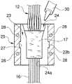
図1は、本発明の一実施形態に係るワイヤハーネスの製造方法に係る止水処理装置の分解斜視図である。
【0020】
図1に示すように、本実施形態に係るワイヤハーネスの止水処理装置11は、グロメット41が取り付けられるワイヤハーネス12のグロメット取付け部位14における電線16間に止水剤(2液反応硬化性のウレタン、エポキシ、シリコン等)17を充填して加熱硬化させることにより、前記グロメット41の電線保持部43の内径以上の外径を備えた止水処理部31を形成するものであり(図6、参照)、アダプター金型21と加熱用金型25とから成る成形金型を有する。
【0021】
前記アダプター金型21は、全体として略円筒状を半割りした形状をなす一対の半割り部品22,23から成り、ワイヤハーネス12のグロメット取付け部位14を挟むように一対の半割り部品22,23を組付けてロックすると、各半割り部品22,23の対向面に形成された半円状の凹部22a,23aが、前記グロメット取付け部位14の電線束を囲んで止水剤17を充填する為の充填空間24を形成する(図3、参照)。
尚、前記アダプター金型21は、前記グロメット取付け部位14の電線束の径が異なる種々のワイヤハーネス12に対応して、前記充填空間24の径が異なる複数種のものが用意される。
【0022】
前記加熱用金型25は、前記アダプター金型21を着脱自在に抱持する取付け凹部26を備えると共に、加熱手段であるヒータユニット28が内蔵されており、抱持した前記アダプター金型21を介して充填空間24内の止水剤17を加熱することができる。
前記取付け凹部26の内壁面には嵌合溝27が刻設されており、前記アダプター金型21の外壁面に突設された嵌合突起22b,23bを挿入案内すると共に、図2に示したように該アダプター金型21を嵌合固定する。
【0023】
次に、上記止水処理装置11を用いてワイヤハーネス12を構成する電線束とグロメット41との間に止水剤17を充填して密封するワイヤハーネスの製造方法を説明する。
先ず、ワイヤハーネス12のグロメット取付け部位14における電線束の径に対応したアダプター金型21を選択し、該グロメット取付け部位14を挟むように一対の半割り部品22,23を組付ける。この際、前記各凹部22a,23aの下端に形成された挟持部24aが、グロメット取付け部位14の電線束を挟持固定する。
【0024】
次に、前記加熱用金型25の嵌合溝27に嵌合突起22b,23bを挿入案内させながら、図2に示したように、前記アダプター金型21を嵌合固定する。すると、図3に示したように、前記グロメット取付け部位14の電線束を囲んで止水剤17を充填する為の略円柱状の充填空間24が形成される。
【0025】
次に、図4に示すように、前記充填空間24内に止水剤17を注入機のノズル30より注入する。該充填空間24の上部は、外方広がりの円錐面とされているので、ノズル30による注入が容易である。
更に、止水剤17の注入が完了した後、加熱用金型25のヒータユニット28によりアダプター金型21を介して充填空間24内の止水剤17を加熱(60〜80℃)し、硬化させる。尚、前記加熱用金型25は、予め温めておくと良い。
【0026】
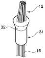
そして、所定時間(10分程度)経過後、これら加熱用金型25及びアダプター金型21からワイヤハーネス12を取り出すと、図5に示したように、該ワイヤハーネス12のグロメット取付け部位14には止水処理部31が形成される。ここで、前記止水処理部31は、グロメット41の電線保持部43の内径以上の外径を備えるように形成されるので、図6に示したように、該電線保持部43内に圧入固定された際には、止水処理部31に対する該電線保持部43の締付け力を一定にでき、グロメット41に止水状態で挿通保持されるワイヤハーネス12の止水性能が安定する。また、前記電線保持部43の先端は、粘着テープ46によりワイヤハーネス46に巻き付け固定される。
【0027】
即ち、本実施形態のワイヤハーネスの製造方法によれば、ワイヤハーネス12のグロメット取付け部位14に設けられる止水処理部31が、予めアダプター金型21の充填空間24内で電線16間に充填した止水剤17を加熱硬化させることにより形成されるので、常温硬化させていた従来に比べて止水剤17の硬化時間を大幅に短縮することができた。
【0028】
そこで、ワイヤハーネス12の組立工程における待ち時間が短くなり、製造リードタイムを短くできると共に、止水剤17が硬化するまでワイヤハーネス17を製造ラインにストックする必要がなくなり、止水処理工程の占有スペースを狭めることができ、生産性向上を図ることができる。
例えば、上記止水処理装置11を4面のターンテーブル上にそれぞれセットし、ワイヤハーネス組立工程のタクトタイムに合わせてハーネスの金型セット、止水剤注入、加熱硬化、離型を繰り返して止水処理することで、非常に効率良くワイヤハーネスを製造することができる。
【0029】
また、上記止水処理装置11によれば、グロメット取付け部位14の電線束の径に対応して充填空間24の径が異なる複数種のアダプター金型21のうちの何れか一つを選択的に加熱用金型25に抱持させることにより、電線束のサイズが異なる複数種のワイヤハーネス12に容易に対応することができる。
【0030】
更に、前記止水処理部31のグロメット拡径部側(図6中、上側)の端部には、半径方向外方へ突出するフランジ部32が設けられている。
そこで、前記止水処理部31がグロメット41の電線保持部43に圧入される際、前記フランジ部32がストッパーとしてグロメット拡径部の内壁に当接するので、位置決めが容易となる。
【0031】
また、前記フランジ部32は、止水処理部31の本体より大きな外径を有しているので、該フランジ部32内に密封される電線束は、前記止水処理部31の本体内に密封される電線束に比べて散けることができ、止水剤17の充填時にはこの電線間に止水剤17が入り込み易くなり、電線間における止水の確実性が更に向上する。
【0032】
図7及び図8は、本発明の一実施形態に係るワイヤハーネスの止水方法を説明する為の止水処理装置の概略断面図である。尚、加熱用金型25等の上記止水処理装置11と同様の構成部品については、同符号を付して詳細な説明を省略する。
図7(a)に示したように、本実施形態のアダプター金型51は、全体として略円筒状を半割りした形状をなす一対の半割り部品52,53から成り、ワイヤハーネス12のグロメット取付け部位14を挟むように一対の半割り部品52,53を組付けてロックすると、各半割り部品52,53の対向面に形成された断面半円状の凹部52a,53aが、前記グロメット取付け部位14の電線束を囲んで止水剤17を充填する為の充填空間54を形成する(図7(b)、参照)。
【0033】
更に、前記充填空間54の上方部には、ワイヤハーネス12のグロメット取付け部位14における電線16間に止水剤17を充填して加熱硬化させることによって形成される止水処理部61(図8(c)、参照)の外径より大きな径を有する拡大空間54aを形成する拡径凹部52b,53bが形成されている。
【0034】
そこで、図7(b)に示したように、ワイヤハーネス12のグロメット取付け部位14を挟むように一対の半割り部品52,53を組付ける。この際、前記グロメット取付け部位14の下方には、電線止め部材60が装着される。該電線止め部材60は、樹脂成型リングや、テープ又は発砲シートから成り、電線束の外周面と凹部52a,53aの内周面との間に隙間を形成することで止水剤17を流れ込み易くしている。
更に、前記拡大空間54a内で電線束をほぐし、各電線16を散けさせる。
【0035】
次に、図7(c)に示すように、前記充填空間54内に止水剤17を注入機のノズル30より注入する。この際、拡大空間54a内で電線束をほぐされた各電線16間には、止水剤17が確実に充填される。
更に、止水剤17の注入が完了した後、図8(a)に示したように前記拡大空間54aに一対のスペーサ55,56を補完的に装填し、図8(b)に示すように該拡大空間54aをスペーサ55,56で充塞する。
【0036】
その後、図示しない加熱用金型25のヒータユニット28によりアダプター金型51を介して充填空間54内の止水剤17を加熱し、硬化させる。
そして、所定時間経過後、前記アダプター金型51からワイヤハーネス12を取り出すと、図8(c)に示したように、該ワイヤハーネス12のグロメット取付け部位14には止水処理部61が形成される。
【0037】
即ち、本実施形態のワイヤハーネスの止水方法によれば、前記止水処理部61が設けられるグロメット取付け部位14の電線束は、予めほぐされてから電線16間に止水剤17が充填されるので、電線16間を確実にシールすることができる。
【0038】
更に、前記拡大空間54aがスペーサ55,56で充塞されることにより、止水剤17は、電線束をほぐす為の前記拡大空間54a内では硬化させられないので、加熱硬化された止水処理部61の形状をコンパクトにでき、グロメット41の電線保持部43に該止水処理部61を圧入固定する際の挿入作業性を低下させることもない。
【0039】
図7及び図8は、本発明の一実施形態に係るワイヤハーネスの止水方法を説明する為の止水処理装置の概略断面図である。尚、加熱用金型25等の上記止水処理装置11と同様の構成部品については、同符号を付して詳細な説明を省略する。
図7(a)に示したように、本実施形態のアダプター金型51は、全体として略円筒状を半割りした形状をなす一対の半割り部品52,53から成り、ワイヤハーネス12のグロメット取付け部位14を挟むように一対の半割り部品52,53を組付けてロックすると、各半割り部品52,53の対向面に形成された断面半円状の凹部52a,53aが、前記グロメット取付け部位14の電線束を囲んで止水剤17を充填する為の充填空間54を形成する(図7(b)、参照)。
【0040】
更に、前記充填空間54の上方部には、ワイヤハーネス12のグロメット取付け部位14における電線16間に止水剤17を充填して加熱硬化させることによって形成される止水処理部61(図8(c)、参照)の外径より大きな径を有する拡大空間54aが形成されている。
【0041】
そこで、図7(b)に示したように、ワイヤハーネス12のグロメット取付け部位14を挟むように一対の半割り部品52,53を組付ける。この際、前記グロメット取付け部位14の下方には、電線止め部材60が装着される。該電線止め部材60は、樹脂成型リングや、テープ又は発砲シートから成り、電線束の外周面と凹部52a,53aの内周面との間に隙間を形成することで止水剤17を流れ込み易くしている。
更に、前記拡大空間54a内で電線束をほぐし、各電線16を散けさせる。
【0042】
次に、図7(c)に示すように、前記充填空間54内に止水剤17を注入機のノズル30より注入する。この際、拡大空間54a内で電線束をほぐされた各電線16間には、止水剤17が確実に充填される。
更に、止水剤17の注入が完了した後、図8(a)に示したように前記拡大空間54aに一対のスペーサ55,56を補完的に装填し、図8(b)に示すように該拡大空間54aをスペーサ55,56で充塞する。
【0043】
その後、図示しない加熱用金型25のヒータユニット28によりアダプター金型51を介して充填空間54内の止水剤17を加熱し、硬化させる。
そして、所定時間経過後、前記アダプター金型51からワイヤハーネス12を取り出すと、図8(c)に示したように、該ワイヤハーネス12のグロメット取付け部位14には止水処理部61が形成される。
【0044】
即ち、本実施形態のワイヤハーネスの止水方法によれば、前記止水処理部61が設けられるグロメット取付け部位14の電線束は、予めほぐされてから電線16間に止水剤17が充填されるので、電線16間を確実にシールすることができる。
【0045】
更に、前記拡大空間54aがスペーサ55,56で充塞されることにより、止水剤17は、電線束をほぐす為の前記拡大空間54a内では硬化させられないので、加熱硬化された止水処理部61の形状をコンパクトにでき、グロメット41の電線保持部43に該止水処理部61を圧入固定する際の挿入作業性を低下させることもない。
【0046】
また、図9(a)に示したように、充填空間54内に止水剤17を注入機のノズル30より注入し、該拡大空間54a内で電線束をほぐされた各電線16間に止水剤17を確実に充填した後、図9(b)に示したようにワイヤハーネス12のグロメット取付け部位14を前記充填空間54の下方に変位させることによって、前記拡大空間54a内の止水剤17を前記充填空間54の下方部に流入させた状態で、充填空間54内の止水剤17を加熱し、硬化させる。
【0047】
そこで、上述した実施形態において用いたスペーサ55,56を用いることなく、電線束をほぐす為の拡大空間54a内で止水剤17が硬化するのを阻止することができる。
そして、所定時間経過後、前記アダプター金型51からワイヤハーネス12を取り出すと、図9(c)に示したように、該ワイヤハーネス12のグロメット取付け部位14には止水処理部61が形成される。
【0048】
尚、本発明のワイヤハーネスの製造方法に係る止水処理装置のアダプター金型及び加熱用金型や、グロメット等の構成は、上記各実施形態の構成に限定されるものではなく、本発明の趣旨に基づいて種々の形態を採りうることは勿論である。
【0049】
【発明の効果】
以上説明したように、本発明のワイヤハーネスの製造方法によれば、ワイヤハーネスのグロメット取付け部位に設けられる止水処理部が、予め成形金型内で電線間に充填した止水剤を加熱硬化させることにより形成されるので、止水剤の硬化時間を短縮することができる。
そこで、ワイヤハーネスの組立工程における待ち時間が短くなり、製造リードタイムを短くできると共に、止水剤が硬化するまでワイヤハーネスを製造ラインにストックする必要がなくなり、止水処理工程の占有スペースを狭めることができ、生産性向上を図ることができる。
【0050】
また、グロメットの電線保持部に圧入固定される前記止水処理部が、該電線保持部の内径以上の外径を備えるように予め止水剤を加熱硬化させることにって形成されるので、グロメットの電線保持部は、該止水処理部に対する締付け力を一定にでき、止水性能が安定する。
従って、効率良く電線束とグロメットとの間の止水処理を行うことができる良好なワイヤハーネスの製造方法及び止水方法を提供できる。
【図面の簡単な説明】
【図1】本発明の一実施形態に係るワイヤハーネスの製造方法に係る止水処理装置の分解斜視図である。
【図2】図1に示した止水処理装置の使用状態を示す斜視図である。
【図3】図1に示した止水処理装置を用いたワイヤハーネスの製造方法を説明する為の断面図である。
【図4】図1に示した止水処理装置を用いたワイヤハーネスの製造方法を説明する為の断面図である。
【図5】図1に示した止水処理装置により形成された止水処理部の斜視図である。
【図6】図5に示した止水処理部にグロメットを取付けた状態を示す部分断面図である。
【図7】本発明の一実施形態に係るワイヤハーネスの止水方法を説明する為の止水処理装置の概略断面図である。
【図8】本発明の一実施形態に係るワイヤハーネスの止水方法を説明する為の止水処理装置の概略断面図である。
【図9】本発明の他の実施形態に係るワイヤハーネスの止水方法を説明する為の止水処理装置の概略断面図である。
【図10】従来のグロメットを示す部分断面図である。
【符号の説明】
11 ワイヤハーネスの止水処理装置
12 ワイヤハーネス
14 グロメット取付け部位
16 電線
21 アダプター金型(成形金型)
22 半割り部品
23 半割り部品
24 充填空間
25 加熱用金型(成形金型)
28 ヒータユニット(加熱手段)
31 止水処理部
32 フランジ部[0001]
TECHNICAL FIELD OF THE INVENTION
The present invention relates to a method of manufacturing a wire harness and a method of stopping water, and particularly to a wire bundle and a grommet constituting a wire harness when a wire harness is inserted and held in a mounting hole formed in a vehicle body panel using a grommet. To improve the method of waterproofing a wire harness in which a waterproofing agent is filled and sealed.
[0002]
[Prior art]
For example, as a grommet for inserting and holding a wire harness into a mounting hole formed in a body panel of an automobile, a grommet that seals by filling a water-blocking agent between a wire bundle and a grommet that constitute a wire harness, or a water-stopper There are structures (for example, Patent Documents 1 and 2).
The grommet 1 shown in FIG. 10 is formed by connecting a funnel-shaped grommet main body (expanded portion) 4 to one end of a cylindrical electric
[0003]
Then, the
[0004]
Therefore, in the work of attaching the grommet 1 to the wire harness and the work of filling the waterproofing agent 7, the wire group forming the wire harness is bundled in the first step, bound with an adhesive tape or the like, and the grommet 1 is moved in the second step. The wire harness is inserted through the
[0005]
[Patent Document 1]
JP-A-8-116615 (
[Patent Document 2]
JP-A-9-112754 (page 1, FIG. 6)
[0006]
[Problems to be solved by the invention]
As described above, the step of injecting the water stopping agent 7 into the grommet 1 (fourth step) includes an assembling step of the wire harness (first step to third step) and a finishing step of the wire harness (sixth step). Therefore, it is necessary to perform the process on the line of the wire harness manufacturing process (first process to sixth process), and the injection process of the waterproofing agent 7 cannot be performed on another line or another place. .
The two-liquid urethane sealant or the anaerobic adhesive used as the water-stopping agent 7 requires a curing time of at least one hour at the earliest, and the grommet 1 is filled with the water-stopping agent 7. In the wire harness, a hardening waiting time of one hour or more occurs. Further, since the curing time of the water blocking agent is affected by the ambient temperature, the curing time varies depending on the season, and it is difficult to manage the curing waiting time.
[0007]
Therefore, the conventional method of manufacturing a wire harness has a problem that a waiting time is longer than a setup time and a processing time in an assembling process of the wire harness, and a manufacturing lead time is long.
In addition, there is a problem in that the wire harness must be stocked on the production line until the water-stopping agent cures, and a large space is required for the water-stopping process.
[0008]
Accordingly, an object of the present invention is to solve the above-mentioned problems, and to provide a good method of manufacturing a wire harness and a water stopping method capable of efficiently performing a water stopping process between a wire bundle and a grommet. is there.
[0009]
[Means for Solving the Problems]
The object of the present invention is to provide a grommet mounting portion of a wire harness to which a grommet is mounted, by filling a waterproofing agent between wires in a molding die in advance and heating and curing the grommet to have an inner diameter equal to or larger than the inner diameter of the wire holding portion of the grommet. By providing a water stopping section having an outer diameter and press-fitting and fixing the water stopping section to the wire holding section of the grommet, the wire harness is inserted and held in the grommet in a water stopped state. This is achieved by a method for manufacturing a wire harness.
[0010]
According to the method of manufacturing the wire harness having the above configuration, the water stopping portion provided at the grommet mounting portion of the wire harness is formed by heating and hardening the water stopping agent previously filled between the wires in the molding die. Therefore, the curing time of the water stopping agent can be shortened.
Therefore, the waiting time in the assembly process of the wire harness is shortened, the production lead time can be shortened, and it is not necessary to stock the wire harness in the production line until the waterproofing agent hardens, and the space occupied by the waterproof process is reduced. And productivity can be improved.
[0011]
Further, since the water-stop processing portion press-fitted and fixed to the wire holding portion of the grommet is formed by previously heating and curing the water-stopping agent so as to have an outer diameter equal to or larger than the inner diameter of the wire holding portion, The wire holding portion of the grommet can maintain a constant tightening force on the water stopping portion, and the water stopping performance is stabilized.
[0012]
Further, the object of the present invention is to provide a wire harness to which the grommet is attached, by filling a waterproofing agent between the wires in the grommet attachment portion and heating and curing the wire grommet, so that the grommet has an outer diameter equal to or greater than the inner diameter of the wire holding portion. A method for stopping water of a wire harness for forming a water stopping treatment part,
Forming an enlarged space larger than the outer diameter of the water-stopping section above the water-stopping agent filling space formed around the wire bundle at the grommet attachment site, and loosening the wire bundle in the enlarged space; Injecting a water-stopping agent into the filling space to fill the space between the wires with a water-stopping agent, complementarily loading and enclosing a spacer in the enlarged space, and filling the water-stopping agent in the filling space. And a step of curing by heating.
[0013]
Further, the object of the present invention is to provide a wire harness to which a grommet is attached, by filling a waterproofing agent between wires in a grommet attachment portion and heating and curing the wire, so that the grommet has an outer diameter equal to or greater than the inner diameter of a wire holding portion of the grommet. A method for stopping water of a wire harness for forming a water stopping treatment part,
Forming an enlarged space larger than the outer diameter of the water-stopping section above the water-stopping agent filling space formed around the wire bundle at the grommet attachment site, and loosening the wire bundle in the enlarged space; Filling a water-blocking agent between the electric wires by injecting a water-blocking agent into the filling space; and displacing the grommet mounting portion below the filling space to fill the water-blocking agent in the enlarged space with the filling space. And a step of heating and curing the water-stopping agent in the filling space.
[0014]
According to the water stopping method of the wire harness having the above configuration, the wire bundle at the grommet mounting portion where the water stopping portion is provided is loosened in advance and then filled with a waterproofing agent between the wires, so that the space between the wires is securely formed. Can be sealed. Further, since the water-stopping agent is not cured in the enlarged space for loosening the wire bundle, the shape of the heat-cured water-stopping portion becomes compact.
[0015]
Further, the object of the present invention is to provide a wire harness to which the grommet is attached, by filling a waterproofing agent between the wires in the grommet attachment portion and heating and curing the wire grommet, so that the grommet has an outer diameter equal to or greater than the inner diameter of the wire holding portion. A wire harness water-stopping device for forming a water-stopping portion,
A heating mold including an adapter mold surrounding the wire bundle at the grommet attachment site to form a space for filling the water blocking agent, and heating means capable of heating the water blocking agent via the held adapter mold. And a mold,
Any one of a plurality of types of adapter dies having different diameters of the filling space is detachably held by the heating die in accordance with the diameter of the wire bundle at the grommet mounting portion. This is achieved by a water stopping device for a wire harness.
[0016]
According to the wire harness water stoppage treatment device having the above configuration, one of a plurality of types of adapter dies having different filling space diameters corresponding to the diameter of the wire bundle at the grommet mounting portion is selectively heated. By holding the wire harness in the tool, it is possible to easily cope with a plurality of types of wire harnesses having different sizes of the wire bundle.
[0017]
Further, the above object of the present invention is to fill a grommet mounting portion of a wire harness to which a grommet is mounted, a water blocking agent between wires in a molding die in advance, and heat-curing the wire grommet to thereby obtain an inner diameter of a wire holding portion of the grommet. A water-stop processing portion having the above outer diameter is provided, and a flange portion projecting outward in the radial direction is provided at an end of the grommet enlarged-diameter portion side of the water-stop processing portion. This is achieved by the waterproof structure of the wire harness.
[0018]
According to the water stopping structure of the wire harness having the above configuration, when the water stopping portion is press-fitted into the wire holding portion of the grommet, the flange portion provided at the end of the grommet on the grommet expanding portion side of the water stopping portion is provided with the stopper. As a result, the abutment with the inner wall of the grommet enlarged diameter portion facilitates positioning.
Further, since the flange portion has an outer diameter larger than that of the water stopping portion, the wire bundle sealed in the flange portion may be scattered compared to the wire bundle sealed in the water stopping portion. When filling, the water-stopping agent easily enters between the electric wires, and the reliability of the water-stop between the electric wires is further improved.
[0019]
BEST MODE FOR CARRYING OUT THE INVENTION
Hereinafter, a method for manufacturing a wire harness and a method for stopping water according to an embodiment of the present invention will be described in detail with reference to the accompanying drawings.
FIG. 1 is an exploded perspective view of a water stopping device according to a method for manufacturing a wire harness according to an embodiment of the present invention.
[0020]
As shown in FIG. 1, the
[0021]
The
A plurality of types of adapter dies 21 having different diameters of the filling
[0022]
The
A
[0023]
Next, a method of manufacturing a wire harness in which the
First, an
[0024]
Next, as shown in FIG. 2, the
[0025]
Next, as shown in FIG. 4, the
Further, after the injection of the
[0026]
After a predetermined time (about 10 minutes), the
[0027]
That is, according to the manufacturing method of the wire harness of the present embodiment, the
[0028]
Therefore, the waiting time in the assembling process of the
For example, the
[0029]
Further, according to the water
[0030]
Further, a
Therefore, when the
[0031]
Further, since the
[0032]
FIG. 7 and FIG. 8 are schematic cross-sectional views of a water stoppage processing device for describing a water stoppage method for a wire harness according to an embodiment of the present invention. Note that the same components as those of the above-described
As shown in FIG. 7A, the
[0033]
Further, in the upper part of the filling
[0034]
Therefore, as shown in FIG. 7B, a pair of
Further, the electric wire bundle is loosened in the
[0035]
Next, as shown in FIG. 7C, the
Further, after the injection of the
[0036]
Then, the
After a predetermined time has elapsed, when the
[0037]
That is, according to the water stopping method of the wire harness of the present embodiment, the wire bundle at the
[0038]
Further, since the
[0039]
FIG. 7 and FIG. 8 are schematic cross-sectional views of a water stoppage processing device for describing a water stoppage method for a wire harness according to an embodiment of the present invention. Note that the same components as those of the above-described
As shown in FIG. 7A, the
[0040]
Further, in the upper part of the filling
[0041]
Therefore, as shown in FIG. 7B, a pair of
Further, the electric wire bundle is loosened in the
[0042]
Next, as shown in FIG. 7C, the
Further, after the injection of the
[0043]
Then, the
After a predetermined time has elapsed, when the
[0044]
That is, according to the water stopping method of the wire harness of the present embodiment, the wire bundle at the
[0045]
Further, since the
[0046]
Further, as shown in FIG. 9 (a), the
[0047]
Therefore, it is possible to prevent the
After a predetermined time has elapsed, when the
[0048]
In addition, the configuration of the adapter mold and the heating mold of the water stopping device according to the method of manufacturing the wire harness of the present invention, and the configurations of the grommets and the like are not limited to the configurations of the above-described embodiments, and the present invention is not limited thereto. Of course, various forms can be adopted based on the purpose.
[0049]
【The invention's effect】
As described above, according to the method for manufacturing a wire harness of the present invention, the water stopping section provided at the grommet mounting portion of the wire harness heat-cures the water stopping agent previously filled between the wires in the molding die. The hardening time of the water-stopping agent can be shortened since the water-stopping agent is formed.
Therefore, the waiting time in the assembly process of the wire harness is shortened, the production lead time can be shortened, and it is not necessary to stock the wire harness in the production line until the waterproofing agent hardens, and the space occupied by the waterproof process is reduced. And productivity can be improved.
[0050]
Further, since the water-stop processing portion press-fitted and fixed to the wire holding portion of the grommet is formed by previously heating and curing the water-stopping agent so as to have an outer diameter equal to or larger than the inner diameter of the wire holding portion, The wire holding portion of the grommet can maintain a constant tightening force on the water stopping portion, and the water stopping performance is stabilized.
Therefore, it is possible to provide a favorable method of manufacturing a wire harness and a water stopping method capable of efficiently performing the water stopping process between the wire bundle and the grommet.
[Brief description of the drawings]
FIG. 1 is an exploded perspective view of a water stopping device according to a method for manufacturing a wire harness according to an embodiment of the present invention.
FIG. 2 is a perspective view showing a usage state of the water stoppage processing device shown in FIG.
FIG. 3 is a cross-sectional view for explaining a method of manufacturing a wire harness using the water stopping device shown in FIG.
FIG. 4 is a cross-sectional view for explaining a method of manufacturing a wire harness using the water stopping device shown in FIG.
FIG. 5 is a perspective view of a water stop processing section formed by the water stop processing device shown in FIG. 1;
FIG. 6 is a partial cross-sectional view showing a state in which a grommet is attached to the water stopping section shown in FIG.
FIG. 7 is a schematic cross-sectional view of a water stopping apparatus for explaining a method of stopping water of a wire harness according to an embodiment of the present invention.
FIG. 8 is a schematic cross-sectional view of a water stopping device for explaining a method of stopping water of a wire harness according to an embodiment of the present invention.
FIG. 9 is a schematic cross-sectional view of a water stopping device for explaining a method of stopping water of a wire harness according to another embodiment of the present invention.
FIG. 10 is a partial sectional view showing a conventional grommet.
[Explanation of symbols]
DESCRIPTION OF
22 Half-
28 Heater unit (heating means)
31 Water
Claims (5)
Translated fromJapanese前記グロメット取付け部位の電線束を囲んで形成される前記止水剤の充填空間上方部に前記止水処理部の外径より大きな拡大空間を形成して該拡大空間内で電線束をほぐす工程と、前記充填空間に止水剤を注入して電線間に止水剤を充填する工程と、前記拡大空間にスペーサを補完的に装填して充塞する工程と、前記充填空間内の止水剤を加熱硬化する工程とを備えたことを特徴とするワイヤハーネスの止水方法。Filling a water-stopping agent between the wires at the grommet mounting portion of the wire harness to which the grommet is mounted and heat-curing to form a water-stop processing portion having an outer diameter equal to or larger than the inner diameter of the wire holding portion of the grommet. The method of stopping water of the wire harness of
Forming an enlarged space larger than the outer diameter of the water-stopping section above the water-stopping agent filling space formed around the wire bundle at the grommet attachment site, and loosening the wire bundle in the enlarged space; Injecting a water-stopping agent into the filling space to fill the space between the wires with a water-stopping agent, complementarily loading and enclosing a spacer in the enlarged space, and filling the water-stopping agent in the filling space. A step of heating and curing the wire harness.
前記グロメット取付け部位の電線束を囲んで形成される前記止水剤の充填空間上方部に前記止水処理部の外径より大きな拡大空間を形成して該拡大空間内で電線束をほぐす工程と、前記充填空間に止水剤を注入して電線間に止水剤を充填する工程と、前記グロメット取付け部位を前記充填空間の下方に変位させて前記拡大空間内の止水剤を前記充填空間の下方部に流入させる工程と、前記充填空間内の止水剤を加熱硬化する工程とを備えたことを特徴とするワイヤハーネスの止水方法。Filling a water-stopping agent between the wires at the grommet mounting portion of the wire harness to which the grommet is mounted and heat-curing to form a water-stop processing portion having an outer diameter equal to or larger than the inner diameter of the wire holding portion of the grommet. The method of stopping water of the wire harness of
Forming an enlarged space larger than the outer diameter of the water-stopping section above the water-stopping agent filling space formed around the wire bundle at the grommet attachment site, and loosening the wire bundle in the enlarged space; Filling a water-blocking agent between the electric wires by injecting a water-blocking agent into the filling space; and displacing the grommet mounting portion below the filling space to fill the water-blocking agent in the enlarged space with the filling space. And a step of heating and curing the water-stopping agent in the filling space.
前記グロメット取付け部位の電線束を囲んで前記止水剤の充填空間を形成するアダプター金型と、抱持した前記アダプター金型を介して前記止水剤を加熱可能な加熱手段を備えた加熱用金型とを有しており、
前記充填空間の径が異なる複数種のアダプター金型のうちの何れか一つが、前記グロメット取付け部位の電線束の径に対応して前記加熱用金型に着脱自在に抱持されることを特徴とするワイヤハーネスの止水処理装置。Filling a water-stopping agent between the wires at the grommet mounting portion of the wire harness to which the grommet is mounted and heat-curing to form a water-stop processing portion having an outer diameter equal to or larger than the inner diameter of the wire holding portion of the grommet. A wire harness water stop treatment device,
A heating mold including an adapter mold surrounding the wire bundle at the grommet attachment site to form a space for filling the water blocking agent, and heating means capable of heating the water blocking agent via the held adapter mold. And a mold,
Any one of a plurality of types of adapter dies having different diameters of the filling space is detachably held by the heating die in accordance with the diameter of the wire bundle at the grommet mounting portion. Water treatment device for wire harness.
Priority Applications (1)
| Application Number | Priority Date | Filing Date | Title |
|---|---|---|---|
| JP2002311287AJP4043914B2 (en) | 2002-10-25 | 2002-10-25 | Water shutoff method and water shutoff treatment device for wire harness |
Applications Claiming Priority (1)
| Application Number | Priority Date | Filing Date | Title |
|---|---|---|---|
| JP2002311287AJP4043914B2 (en) | 2002-10-25 | 2002-10-25 | Water shutoff method and water shutoff treatment device for wire harness |
Publications (2)
| Publication Number | Publication Date |
|---|---|
| JP2004146254Atrue JP2004146254A (en) | 2004-05-20 |
| JP4043914B2 JP4043914B2 (en) | 2008-02-06 |
Family
ID=32456562
Family Applications (1)
| Application Number | Title | Priority Date | Filing Date |
|---|---|---|---|
| JP2002311287AExpired - Fee RelatedJP4043914B2 (en) | 2002-10-25 | 2002-10-25 | Water shutoff method and water shutoff treatment device for wire harness |
Country Status (1)
| Country | Link |
|---|---|
| JP (1) | JP4043914B2 (en) |
Cited By (19)
| Publication number | Priority date | Publication date | Assignee | Title |
|---|---|---|---|---|
| JP2007052992A (en)* | 2005-08-17 | 2007-03-01 | Auto Network Gijutsu Kenkyusho:Kk | Water stop treatment method for in-vehicle electric wires |
| JP2009289603A (en)* | 2008-05-29 | 2009-12-10 | Yazaki Corp | Method of water stop processing of electric wire bundle of wiring harness, apparatus of water stop processing of electric wire bundle of wire harness, and wire harness |
| JP2009289604A (en)* | 2008-05-29 | 2009-12-10 | Yazaki Corp | Method of water stop processing of electric wire, apparatus of water stop processing of electric wire, and wire harness |
| JP2009289605A (en)* | 2008-05-29 | 2009-12-10 | Yazaki Corp | Method of water stop processing of electric wire, apparatus of water stop processing of electric wire, and wire harness |
| WO2011028762A1 (en)* | 2009-09-02 | 2011-03-10 | Rosemount Inc. | Wire harness for field devices used in hazardous locations |
| US7956738B2 (en) | 2004-06-28 | 2011-06-07 | Rosemount Inc. | Process field device with radio frequency communication |
| US8049361B2 (en) | 2008-06-17 | 2011-11-01 | Rosemount Inc. | RF adapter for field device with loop current bypass |
| US8145180B2 (en) | 2004-05-21 | 2012-03-27 | Rosemount Inc. | Power generation for process devices |
| US8160535B2 (en) | 2004-06-28 | 2012-04-17 | Rosemount Inc. | RF adapter for field device |
| US8694060B2 (en) | 2008-06-17 | 2014-04-08 | Rosemount Inc. | Form factor and electromagnetic interference protection for process device wireless adapters |
| US8787848B2 (en) | 2004-06-28 | 2014-07-22 | Rosemount Inc. | RF adapter for field device with low voltage intrinsic safety clamping |
| US8847571B2 (en) | 2008-06-17 | 2014-09-30 | Rosemount Inc. | RF adapter for field device with variable voltage drop |
| US8929948B2 (en) | 2008-06-17 | 2015-01-06 | Rosemount Inc. | Wireless communication adapter for field devices |
| US9310794B2 (en) | 2011-10-27 | 2016-04-12 | Rosemount Inc. | Power supply for industrial process field device |
| US9674976B2 (en) | 2009-06-16 | 2017-06-06 | Rosemount Inc. | Wireless process communication adapter with improved encapsulation |
| KR20170089561A (en)* | 2016-01-27 | 2017-08-04 | 엘에스전선 주식회사 | Mining Cable Weight Supporting Structure |
| US10761524B2 (en) | 2010-08-12 | 2020-09-01 | Rosemount Inc. | Wireless adapter with process diagnostics |
| CN113161934A (en)* | 2021-04-20 | 2021-07-23 | 常州船用电缆有限责任公司 | Clamp for connecting cable and connector and connecting manufacturing method thereof |
| US11398325B2 (en) | 2019-12-06 | 2022-07-26 | Commscope Technologies Llc | Cable assembly with bundling arrangement |
- 2002
- 2002-10-25JPJP2002311287Apatent/JP4043914B2/ennot_activeExpired - Fee Related
Cited By (23)
| Publication number | Priority date | Publication date | Assignee | Title |
|---|---|---|---|---|
| US8145180B2 (en) | 2004-05-21 | 2012-03-27 | Rosemount Inc. | Power generation for process devices |
| US8160535B2 (en) | 2004-06-28 | 2012-04-17 | Rosemount Inc. | RF adapter for field device |
| US8787848B2 (en) | 2004-06-28 | 2014-07-22 | Rosemount Inc. | RF adapter for field device with low voltage intrinsic safety clamping |
| US7956738B2 (en) | 2004-06-28 | 2011-06-07 | Rosemount Inc. | Process field device with radio frequency communication |
| JP2007052992A (en)* | 2005-08-17 | 2007-03-01 | Auto Network Gijutsu Kenkyusho:Kk | Water stop treatment method for in-vehicle electric wires |
| JP2009289603A (en)* | 2008-05-29 | 2009-12-10 | Yazaki Corp | Method of water stop processing of electric wire bundle of wiring harness, apparatus of water stop processing of electric wire bundle of wire harness, and wire harness |
| JP2009289604A (en)* | 2008-05-29 | 2009-12-10 | Yazaki Corp | Method of water stop processing of electric wire, apparatus of water stop processing of electric wire, and wire harness |
| JP2009289605A (en)* | 2008-05-29 | 2009-12-10 | Yazaki Corp | Method of water stop processing of electric wire, apparatus of water stop processing of electric wire, and wire harness |
| US8694060B2 (en) | 2008-06-17 | 2014-04-08 | Rosemount Inc. | Form factor and electromagnetic interference protection for process device wireless adapters |
| US8847571B2 (en) | 2008-06-17 | 2014-09-30 | Rosemount Inc. | RF adapter for field device with variable voltage drop |
| US8049361B2 (en) | 2008-06-17 | 2011-11-01 | Rosemount Inc. | RF adapter for field device with loop current bypass |
| US8929948B2 (en) | 2008-06-17 | 2015-01-06 | Rosemount Inc. | Wireless communication adapter for field devices |
| US9674976B2 (en) | 2009-06-16 | 2017-06-06 | Rosemount Inc. | Wireless process communication adapter with improved encapsulation |
| US8626087B2 (en) | 2009-06-16 | 2014-01-07 | Rosemount Inc. | Wire harness for field devices used in a hazardous locations |
| WO2011028762A1 (en)* | 2009-09-02 | 2011-03-10 | Rosemount Inc. | Wire harness for field devices used in hazardous locations |
| US10761524B2 (en) | 2010-08-12 | 2020-09-01 | Rosemount Inc. | Wireless adapter with process diagnostics |
| US9310794B2 (en) | 2011-10-27 | 2016-04-12 | Rosemount Inc. | Power supply for industrial process field device |
| KR20170089561A (en)* | 2016-01-27 | 2017-08-04 | 엘에스전선 주식회사 | Mining Cable Weight Supporting Structure |
| KR102543318B1 (en)* | 2016-01-27 | 2023-06-13 | 엘에스전선 주식회사 | Mining Cable Weight Supporting Structure |
| US11398325B2 (en) | 2019-12-06 | 2022-07-26 | Commscope Technologies Llc | Cable assembly with bundling arrangement |
| US11728071B2 (en) | 2019-12-06 | 2023-08-15 | Commscope Technologies Llc | Cable assembly with bundling arrangement |
| CN113161934A (en)* | 2021-04-20 | 2021-07-23 | 常州船用电缆有限责任公司 | Clamp for connecting cable and connector and connecting manufacturing method thereof |
| CN113161934B (en)* | 2021-04-20 | 2022-06-07 | 常州船用电缆有限责任公司 | Clamp for connecting cable and connector and connecting manufacturing method thereof |
Also Published As
| Publication number | Publication date |
|---|---|
| JP4043914B2 (en) | 2008-02-06 |
Similar Documents
| Publication | Publication Date | Title |
|---|---|---|
| JP2004146254A (en) | Method of manufacturing wire harness and method of stopping water | |
| US6010134A (en) | Sealed grommet for wire harnesses having a split cylindrical core member with a complementary grommet sleeve | |
| JP5391773B2 (en) | Line water stop method to wire harness | |
| JP2008117616A (en) | Inter-wire water stop structure and inter-wire water stop method | |
| CN102312889A (en) | Fastening elements for slender materials | |
| JPH10243539A (en) | Splice wire waterproof structure and splice wire waterproofing method | |
| US6624361B2 (en) | Method of waterproofing wire harness | |
| JP6721429B2 (en) | Wire harness manufacturing method | |
| JP2003016859A (en) | Manufacturing method of waterproof wire harness | |
| JP6374898B2 (en) | Manufacturing method of wire harness | |
| JP2767731B2 (en) | Grommet waterproof structure | |
| JP3341442B2 (en) | Grommet | |
| CN107538673A (en) | The manufacture method of wire harness | |
| JP2866571B2 (en) | Water stopping structure of grommet and method of stopping water | |
| JP2019216070A (en) | Waterproof structure of exposed portion of core wire | |
| JPH07249338A (en) | Grommet and forming method thereof | |
| JP2002078161A (en) | Apparatus and method for manufacturing line waterproof body | |
| JPH10243533A (en) | Waterproof structure of grommet for automobile | |
| JP5488299B2 (en) | Grommet water stop structure manufacturing method and grommet water stop structure | |
| JP3379447B2 (en) | Grommet spacer and grommet provided with the spacer | |
| JPS6229082A (en) | Lead wire terminal covering structure | |
| JPH0448098Y2 (en) | ||
| JP2904026B2 (en) | Jig for forming waterproof structure of grommet | |
| JP3052800B2 (en) | Spacer for wire harness and waterproof structure of splice portion of wire harness using the spacer | |
| JP2003047137A (en) | Grommet |
Legal Events
| Date | Code | Title | Description |
|---|---|---|---|
| A621 | Written request for application examination | Free format text:JAPANESE INTERMEDIATE CODE: A621 Effective date:20050126 | |
| RD04 | Notification of resignation of power of attorney | Free format text:JAPANESE INTERMEDIATE CODE: A7424 Effective date:20060325 | |
| A977 | Report on retrieval | Free format text:JAPANESE INTERMEDIATE CODE: A971007 Effective date:20070723 | |
| A131 | Notification of reasons for refusal | Free format text:JAPANESE INTERMEDIATE CODE: A131 Effective date:20070801 | |
| A521 | Written amendment | Free format text:JAPANESE INTERMEDIATE CODE: A523 Effective date:20070925 | |
| TRDD | Decision of grant or rejection written | ||
| A01 | Written decision to grant a patent or to grant a registration (utility model) | Free format text:JAPANESE INTERMEDIATE CODE: A01 Effective date:20071107 | |
| A61 | First payment of annual fees (during grant procedure) | Free format text:JAPANESE INTERMEDIATE CODE: A61 Effective date:20071114 | |
| R150 | Certificate of patent or registration of utility model | Free format text:JAPANESE INTERMEDIATE CODE: R150 | |
| FPAY | Renewal fee payment (event date is renewal date of database) | Free format text:PAYMENT UNTIL: 20101122 Year of fee payment:3 | |
| RD04 | Notification of resignation of power of attorney | Free format text:JAPANESE INTERMEDIATE CODE: A7424 Effective date:20071129 | |
| LAPS | Cancellation because of no payment of annual fees |