JP2004146169A - Marker lamp for vehicles - Google Patents
Marker lamp for vehiclesDownload PDFInfo
- Publication number
- JP2004146169A JP2004146169AJP2002309107AJP2002309107AJP2004146169AJP 2004146169 AJP2004146169 AJP 2004146169AJP 2002309107 AJP2002309107 AJP 2002309107AJP 2002309107 AJP2002309107 AJP 2002309107AJP 2004146169 AJP2004146169 AJP 2004146169A
- Authority
- JP
- Japan
- Prior art keywords
- light
- light emitting
- lamp
- emitting region
- red
- Prior art date
- Legal status (The legal status is an assumption and is not a legal conclusion. Google has not performed a legal analysis and makes no representation as to the accuracy of the status listed.)
- Granted
Links
- 239000003550markerSubstances0.000titleclaimsabstractdescription21
- 238000009792diffusion processMethods0.000claimsdescription10
- 238000012986modificationMethods0.000description6
- 230000004048modificationEffects0.000description6
- 239000000758substrateSubstances0.000description3
- XAGFODPZIPBFFR-UHFFFAOYSA-NaluminiumChemical compound[Al]XAGFODPZIPBFFR-UHFFFAOYSA-N0.000description1
- 229910052782aluminiumInorganic materials0.000description1
- 230000015572biosynthetic processEffects0.000description1
- 230000000694effectsEffects0.000description1
- 230000005499meniscusEffects0.000description1
- 238000000034methodMethods0.000description1
- 230000003287optical effectEffects0.000description1
- 238000007740vapor depositionMethods0.000description1
Images


Classifications
- B—PERFORMING OPERATIONS; TRANSPORTING
- B60—VEHICLES IN GENERAL
- B60Q—ARRANGEMENT OF SIGNALLING OR LIGHTING DEVICES, THE MOUNTING OR SUPPORTING THEREOF OR CIRCUITS THEREFOR, FOR VEHICLES IN GENERAL
- B60Q1/00—Arrangement of optical signalling or lighting devices, the mounting or supporting thereof or circuits therefor
- B60Q1/26—Arrangement of optical signalling or lighting devices, the mounting or supporting thereof or circuits therefor the devices being primarily intended to indicate the vehicle, or parts thereof, or to give signals, to other traffic
- B60Q1/2607—Arrangement of optical signalling or lighting devices, the mounting or supporting thereof or circuits therefor the devices being primarily intended to indicate the vehicle, or parts thereof, or to give signals, to other traffic comprising at least two indicating lamps
- B—PERFORMING OPERATIONS; TRANSPORTING
- B60—VEHICLES IN GENERAL
- B60Q—ARRANGEMENT OF SIGNALLING OR LIGHTING DEVICES, THE MOUNTING OR SUPPORTING THEREOF OR CIRCUITS THEREFOR, FOR VEHICLES IN GENERAL
- B60Q1/00—Arrangement of optical signalling or lighting devices, the mounting or supporting thereof or circuits therefor
- B60Q1/0029—Spatial arrangement
- B60Q1/0041—Spatial arrangement of several lamps in relation to each other
- B60Q1/0058—Stacked, i.e. one lamp located behind the other in the optical axis direction
- F—MECHANICAL ENGINEERING; LIGHTING; HEATING; WEAPONS; BLASTING
- F21—LIGHTING
- F21S—NON-PORTABLE LIGHTING DEVICES; SYSTEMS THEREOF; VEHICLE LIGHTING DEVICES SPECIALLY ADAPTED FOR VEHICLE EXTERIORS
- F21S43/00—Signalling devices specially adapted for vehicle exteriors, e.g. brake lamps, direction indicator lights or reversing lights
- F21S43/20—Signalling devices specially adapted for vehicle exteriors, e.g. brake lamps, direction indicator lights or reversing lights characterised by refractors, transparent cover plates, light guides or filters
- F21S43/235—Light guides
- F21S43/236—Light guides characterised by the shape of the light guide
- F21S43/237—Light guides characterised by the shape of the light guide rod-shaped
- F—MECHANICAL ENGINEERING; LIGHTING; HEATING; WEAPONS; BLASTING
- F21—LIGHTING
- F21S—NON-PORTABLE LIGHTING DEVICES; SYSTEMS THEREOF; VEHICLE LIGHTING DEVICES SPECIALLY ADAPTED FOR VEHICLE EXTERIORS
- F21S43/00—Signalling devices specially adapted for vehicle exteriors, e.g. brake lamps, direction indicator lights or reversing lights
- F21S43/20—Signalling devices specially adapted for vehicle exteriors, e.g. brake lamps, direction indicator lights or reversing lights characterised by refractors, transparent cover plates, light guides or filters
- F21S43/235—Light guides
- F21S43/242—Light guides characterised by the emission area
- F21S43/245—Light guides characterised by the emission area emitting light from one or more of its major surfaces
- F—MECHANICAL ENGINEERING; LIGHTING; HEATING; WEAPONS; BLASTING
- F21—LIGHTING
- F21S—NON-PORTABLE LIGHTING DEVICES; SYSTEMS THEREOF; VEHICLE LIGHTING DEVICES SPECIALLY ADAPTED FOR VEHICLE EXTERIORS
- F21S43/00—Signalling devices specially adapted for vehicle exteriors, e.g. brake lamps, direction indicator lights or reversing lights
- F21S43/20—Signalling devices specially adapted for vehicle exteriors, e.g. brake lamps, direction indicator lights or reversing lights characterised by refractors, transparent cover plates, light guides or filters
- F21S43/235—Light guides
- F21S43/247—Light guides with a single light source being coupled into the light guide
- F—MECHANICAL ENGINEERING; LIGHTING; HEATING; WEAPONS; BLASTING
- F21—LIGHTING
- F21S—NON-PORTABLE LIGHTING DEVICES; SYSTEMS THEREOF; VEHICLE LIGHTING DEVICES SPECIALLY ADAPTED FOR VEHICLE EXTERIORS
- F21S43/00—Signalling devices specially adapted for vehicle exteriors, e.g. brake lamps, direction indicator lights or reversing lights
- F21S43/20—Signalling devices specially adapted for vehicle exteriors, e.g. brake lamps, direction indicator lights or reversing lights characterised by refractors, transparent cover plates, light guides or filters
- F21S43/26—Refractors, transparent cover plates, light guides or filters not provided in groups F21S43/235 - F21S43/255
- F—MECHANICAL ENGINEERING; LIGHTING; HEATING; WEAPONS; BLASTING
- F21—LIGHTING
- F21S—NON-PORTABLE LIGHTING DEVICES; SYSTEMS THEREOF; VEHICLE LIGHTING DEVICES SPECIALLY ADAPTED FOR VEHICLE EXTERIORS
- F21S43/00—Signalling devices specially adapted for vehicle exteriors, e.g. brake lamps, direction indicator lights or reversing lights
- F21S43/10—Signalling devices specially adapted for vehicle exteriors, e.g. brake lamps, direction indicator lights or reversing lights characterised by the light source
- F21S43/13—Signalling devices specially adapted for vehicle exteriors, e.g. brake lamps, direction indicator lights or reversing lights characterised by the light source characterised by the type of light source
- F21S43/14—Light emitting diodes [LED]
Landscapes
- Engineering & Computer Science (AREA)
- General Engineering & Computer Science (AREA)
- Mechanical Engineering (AREA)
- Non-Portable Lighting Devices Or Systems Thereof (AREA)
Abstract
Description
Translated fromJapanese【0001】
【発明の属する技術分野】
本願発明は、赤色で点灯するように構成された車両用標識灯に関するものである。
【0002】
【従来の技術】
一般に、テール&ストップランプ等のように赤色で点灯する車両用標識灯においては、例えば「特許文献1」に記載されているように赤色透明の透光カバーを備えた構成となっている。一方、「特許文献2」には、テール&ストップランプにおいて、光源と透光カバーとの間に赤色透明の透光部材が設けられた構成が記載されている。
【0003】
【特許文献1】
特開2000−195309号公報
【特許文献2】
特開2000−322905号公報
【発明が解決しようとする課題】
しかしながら、上記従来の車両用標識灯においては、透光カバー全体あるいは透光部材全体が赤色透明の部材で構成されているので、灯具点灯時には灯具全体が比較的単調な赤色で光って見えてしまうこととなり、斬新性のある見映えを得ることができない、という問題がある。
【0004】
本願発明は、このような事情に鑑みてなされたものであって、赤色で点灯するように構成された車両用標識灯において、灯具点灯時の見映えに斬新性を持たせることができる車両用標識灯を提供することを目的とするものである。
【0005】
【課題を解決するための手段】
本願発明は、透光部材に対する光入射方法に工夫を施すことにより該透光部材に直接発光領域および間接発光領域を設けるとともに、これらを赤色透明領域と無色透明領域とに割り振ることにより、上記目的達成を図るようにしたものである。
【0006】
すなわち、本願発明に係る車両用標識灯は、
ランプボディとこのランプボディの前端開口部に取り付けられた透光カバーとで構成される灯室内に、複数の光源と上記透光カバーに略沿って延びるように配置された透光部材とが収容されてなり、赤色で点灯するように構成された車両用標識灯において、
上記複数の光源として、上記透光部材の後方側に配置された第1光源と、上記透光部材の側端部近傍に配置された第2光源とを備えており、
上記透光部材に、上記第1光源から該透光部材に入射した光を前方へ透過させる直接発光領域と、上記第2光源から該透光部材に入射した光を内面反射により前方へ出射させる間接発光領域とが設けられており、これら直接発光領域および間接発光領域のうち一方の領域が赤色透明領域として構成されるとともに他方の領域が無色透明領域として構成されている、ことを特徴とするものである。
【0007】
上記「車両用標識灯」は、赤色で点灯するように構成されたものであれば、特定種類の車両用標識灯に限定されるものではなく、例えば、テールランプ、ストップランプ、テール&ストップランプ、リヤフォグランプ等が採用可能である。なお、テール&ストップランプである場合には、テールランプ点灯モードおよびストップランプ点灯モードの双方において第1光源および第2光源を同時点灯させる構成としてもよいし、また、テールランプ点灯モードでは第1光源および第2光源のいずれか一方を点灯させるとともにストップランプ点灯モードでは第1光源および第2光源の他方あるいは双方を点灯させる構成、あるいはその逆の構成としてもよい。
【0008】
上記「透光カバー」の色は、赤色透明であってよいことはもちろんであるが、無色透明であってもよく、また、車両用標識灯が赤色で点灯して見える色度範囲内であれば、赤色以外の有色の透明であってもよい。
【0009】
上記各「光源」は、赤色で発光する光源であってよいことはもちろんであるが、白色で発光する光源であってもよい。また、これら各「光源」の種類は特に限定されるものではなく、例えば発光ダイオードや白熱バルブ等が採用可能である。
【0010】
上記透光部材における「直接発光領域」および「間接発光領域」の形成位置、大きさ、形状等の具体的構成は、特に限定されるものではない。
【0011】
【発明の作用効果】
上記構成に示すように、本願発明に係る車両用標識灯は、透光カバーに略沿って延びる透光部材を備えた赤色で点灯する灯具であるが、透光部材の後方側には第1光源が配置されるとともに透光部材の側端部近傍には第2光源が配置されており、また透光部材には第1光源からの入射光を前方へ透過させる直接発光領域と第2光源からの入射光を内面反射により前方へ出射させる間接発光領域とが設けられているので、灯具点灯時、直接発光領域と間接発光領域との間で発光の態様を異なったものとすることができる。
【0012】
しかも透光部材は、その直接発光領域および間接発光領域のうち一方の領域が赤色透明領域として構成されるとともに他方の領域が無色透明領域として構成されているので、灯具点灯時、直接発光領域と間接発光領域との間で赤色濃度に差異を持たせることができる。
【0013】
そして、このように発光態様および赤色濃度に差異を持たせることにより、直接発光領域の見え方と間接発光領域の見え方とを大きく異なったものとすることができる。
【0014】
したがって本願発明によれば、赤色で点灯するように構成された車両用標識灯において、灯具点灯時の見映えに斬新性を持たせることができる。
【0015】
しかも本願発明に係る車両用標識灯においては、直接発光領域と間接発光領域との間の赤色濃度差により、赤色の濃淡を有する灯具意匠を得ることができるので、灯具非点灯時の見映えに関しても斬新性を持たせることができる。
【0016】
上記構成において、赤色透明領域への光入射を行う光源を、赤色で発光する光源で構成するようにすれば、灯具点灯時、赤色透明領域を一層高濃度の赤色で光って見えるようにすることができる。この場合において、無色透明領域への光入射を行う光源に関して、これを赤色で発光する光源で構成するようにすれば、無色透明領域についても赤色高濃度化を図ることができ、一方、これを白色で発光する光源で構成するようにすれば、赤色透明領域と無色透明領域との間の赤色濃淡差を大きくして、そのコントラストにより灯具点灯時の見映えに一層の斬新性を持たせることができる。
【0017】
また上記構成において、直接発光領域を赤色透明領域として設定した上で、この直接発光領域と第1光源との間に赤色透明の第2透光部材を設けるようにすれば、灯具点灯時、赤色透明領域をより一層高濃度の赤色で光って見えるようにすることができる。この場合において、第2透光部材を上記透光部材の一部として構成すれば、灯具構成を簡素化することができる。
【0018】
さらに上記構成において、透光部材を、透光カバーに略沿って互いに略平行に延びる複数のフィンを備えた構成とし、これら各フィン毎に第2光源を配置するとともに、これら各フィンの後端面における間接発光領域に位置する部位に第2光源からの入射光を前方へ出射させるための複数の反射素子を形成するようにすれば、灯具点灯時、間接発光領域を縞状に光って見えるようにすることができる。そしてこれにより、直接発光領域の見え方と間接発光領域の見え方とを全く異なったものとすることができるので、灯具点灯時における灯具意匠の斬新性をより一層高めることができる。この場合において、上記各「反射素子」の具体的構成は特に限定されるものではなく、例えば、溝状に形成されたものや点刻状に形成されたもの等が採用可能である。
【0019】
また上記構成において、直接発光領域の少なくとも一部に、第1光源からの光を拡散透過させるための光拡散処理を施すようにすれば、該光拡散処理が施された部分に関しては均一性のある光り方を実現することができる。この場合において、上記「光拡散処理」の種類は特に限定されるものではなく、例えば、シボ加工やフロスト加工を施すこと、あるいは複数の反射素子を形成すること等により光拡散処理を行うことが可能であり、また、この「光拡散処理」は、直接発光領域の前面および後面のいずれに施すようにしてもよく、その両面に施すようにしてもよい。
【0020】
【発明の実施の形態】
以下、図面を用いて、本願発明の実施形態について説明する。
【0021】
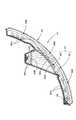
図1は、本願発明の一実施形態に係る車両用標識灯を示す正面図であり、図2および3は、図1のII−II 線断面図およびIII−III 線断面図である。
【0022】
これらの図に示すように、本実施形態に係る車両用標識灯10は、車両右側後端部に設けられるリヤコンビネーションランプであって、テール&ストップランプ12と、ターンシグナルランプ14と、バックアップランプ16とを備えてなっている。なお、以下の説明における「前方」や「後方」等の向きは、車両用標識灯10としての向きであって、車両としての向きとは逆になっている。
【0023】
この車両用標識灯10は、灯具正面視において略横長矩形の外形形状を有しており、ランプボディ22とその前端開口部に取り付けられた透光カバー24とにより、テール&ストップランプ12用の灯室とターンシグナルランプ14用の灯室とバックアップランプ16用の灯室が構成されている。その際、テール&ストップランプ12用の灯室は上段に配置されており、ターンシグナルランプ14用の灯室は下段の車幅方向外側に配置されており、バックアップランプ16用の灯室は下段の車幅方向内側に配置されている。
【0024】
透光カバー24は、その車幅方向内側端部から車幅方向外側端部へ向けて灯具後方側へ大きく回り込むようにして湾曲形成されている。この透光カバー24は、ターンシグナルランプ14用の灯室の前方領域24aおよびバックアップランプ16用の灯室の前方領域24bが無色透明であるが、それ以外の領域は赤色透明である。
【0025】
テール&ストップランプ12は、その灯室内に、第1光源としての2つの発光ダイオード32と、第2光源としての5つの発光ダイオード34と、透光カバー24に略沿って延びるように配置された透光部材36とが収容されてなり、赤色で点灯するように構成されている。
【0026】
2つの発光ダイオード32は、いずれもストップランプ点灯モードで点灯する赤色の発光ダイオードであって、透光部材36の後方側において前方へ向けて配置されている。これら各発光ダイオード32は、基板38を介してランプボディ22に支持されている。
【0027】
一方、5つの発光ダイオード34は、いずれもテールランプ点灯モードで点灯する赤色の発光ダイオードであって、透光部材36の車幅方向内側端部近傍において該透光部材36へ向けて配置されている。これら各発光ダイオード34も、基板40を介してランプボディ22に支持されている。
【0028】
透光部材36は、上下方向に略等間隔をおいて水平方向に延びる5つの無色透明のフィン42と、これら5つのフィン42と一体成形された赤色透明のパネル44とからなる2色成形品として構成されている。
【0029】
各フィン42は、前方へ向けて上下幅が狭まる台形の断面形状を有しており、透光カバー24に略沿って車幅方向内側端部から車幅方向外側端部へ向けて灯具後方側へ大きく回り込むように形成されている。そして、これら各フィン42の車幅方向内側端部近傍に、上記5つの発光ダイオード34が1つずつ配置されている。
【0030】
一方、パネル44は、5つのフィン42の水平方向中間部位において、これらフィン42の後端面に当接するように配置されている。そして、このパネル44の後方側に、上記2つの発光ダイオード32が上下方向に所定間隔をおいて配置されている。
【0031】
そしてこれにより、図4に示すように、透光部材36は、そのパネル44が設けられている部分が、2つの発光ダイオード32から透光部材36に入射した光を前方へ透過させる直接発光領域36Aとして構成されるとともに、この直接発光領域36Aの水平方向両側部位が、5つの発光ダイオード34から透光部材36に入射した光を内面反射により前方へ出射させる間接発光領域36Bとして構成されている。
【0032】
その際、直接発光領域36Aは、赤色透明のパネル44と5つの無色透明のフィン42との部分的な重ね合わせにより赤色透明領域として構成されており、間接発光領域36Bは、5つの無色透明のフィン42のみにより無色透明領域として構成されている。
【0033】
パネル44は、パネル本体44Aと、このパネル本体44Aの車幅方向外側端部から後方へ向けて略L形に延長形成され、2つの発光ダイオード32の前方側において左右方向に延びる第2透光部材としてのパネル延長部44Bとからなっている。パネル44Aの後面には、その全域にわたってシボ加工による光拡散処理が施されており、これにより光拡散面44aを構成している。また、パネル延長部44Bの後面には複数のレンズ素子44sが形成されており、これにより各発光ダイオード32からの発散光を偏向制御してパネル本体44Aへ入射させるようになっている。
【0034】
各フィン42の後端面における間接発光領域36Bに位置する部位には、各発光ダイオード34から各フィン42に入射した光を前方へ出射させるための複数の反射素子42sが形成されている、これら各反射素子42sは、上下方向に延びる縦溝からなり、水平方向に面沿いで略等間隔をおいて形成されている。
【0035】
図1および3に示すように、ターンシグナルランプ14は、その灯室内に、アンバ色で発光する白熱バルブ52と、透光カバー24に略沿って延びるように配置された透光部材54とが収容されてなり、アンバ色で点灯するように構成されている。一方、バックアップランプ16は、その灯室内に、白色で発光する白熱バルブ56と、透光カバー24に略沿って延びるように配置された図示しない透光部材とが収容されてなり、白色で点灯するように構成されている。
【0036】
透光部材54は、その上下方向中央部位54aが凸メニスカスレンズ状に形成されており、その上下両側部位54bが、上下両側に向けて前方側へ略45°の傾斜角度で延びる斜面状に形成されている。そして、これら上下両側部位54bの前面には、アルミニウム蒸着処理等により反射膜58が形成されている。そしてこれにより、ターンシグナルランプ14が点灯したとき、上下方向中央部位54aを透して前方へ照射される白熱バルブ52からの光のうち、反射膜58へ向かう迷光成分を該反射膜58で前方へ反射させて、ターンシグナルランプ14の発光領域の上下幅を大きく確保する一方、非点灯時には、ターンシグナルランプ14の上下幅を狭く見せるようにしている。
【0037】
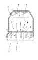
図5は,テール&ストップランプ12を各点灯モードで点灯させたときの見え方を示す正面図であり、同図(a)がテールランプ点灯モード、同図(b)がストップランプ点灯モード、同図(c)がテール&ストップランプ点灯モードでの見え方を示している。
【0038】
上述したように、テールランプ点灯モードでは、5つの発光ダイオード34が点灯する。そして、これら各発光ダイオード34から各フィン42に入射した光は、該フィン42を導光体としてその表面で全反射を繰り返しながら車幅方向外側端部へ向かっていくが、その途中で間接発光領域36Bに形成された反射素子42sに入射した光は、該反射素子42sで灯具前方寄りに反射されてフィン42の前端面から前方へ出射する。このため、テールランプ点灯モードでは、2箇所の間接発光領域36Bにおいて5つのフィン42が上下略等間隔で横縞状に光って見える。その際、各フィン42は無色透明であるが、各発光ダイオード34は赤色で発光しており、透光カバー24は赤色透明であるので、ある程度の濃度を有する赤色で光って見える。
【0039】
一方、ストップランプ点灯モードでは、2つの発光ダイオード32が点灯する。そして、これら各発光ダイオード32からの光は、パネル延長部44Bを介してパネル本体44Aの光拡散面44aに到達し、このパネル本体44Aを拡散透過して前方へ出射する。このため、ストップランプ点灯モードでは、直接発光領域36Aにおいてパネル本体44A全体が略均一に光って見える。その際、各発光ダイオード34は赤色で発光しており、また、パネル延長部44B、パネル本体44Aおよび透光カバー24はいずれも赤色透明であるので、非常に高濃度の赤色で光って見える。
【0040】
さらに、テール&ストップランプ点灯モードでは、5つの発光ダイオード34と2つの発光ダイオード32とが同時に点灯するので、2箇所の間接発光領域36Bにおいて5つのフィン42が上下略等間隔で横縞状に光って見えるとともに、直接発光領域36Aにおいてパネル本体44A全体が略均一に光って見える。
【0041】
以上詳述したように、本実施形態に係る車両用標識灯10において赤色で点灯するテール&ストップランプ12は、赤色透明の透光カバー24に略沿って延びる透光部材36を備えているが、この透光部材36の後方側には2つの発光ダイオード32が配置されるとともにその側端部近傍には5つの発光ダイオード34が配置されており、また、この透光部材36には2つの発光ダイオード32からの入射光を前方へ透過させる直接発光領域36Aと5つの発光ダイオード34からの入射光を内面反射により前方へ出射させる間接発光領域36Bとが設けられているので、灯具点灯時、直接発光領域36Aと間接発光領域36Bとの間で発光の態様を異なったものとすることができる。
【0042】
しかも透光部材36は、その直接発光領域36Aが赤色透明領域として構成されるとともに間接発光領域36Bが無色透明領域として構成されているので、灯具点灯時、直接発光領域36Aと間接発光領域36Bとの間で赤色濃度に差異を持たせることができる。
【0043】
そして、このように発光態様および赤色濃度に差異を持たせることにより、直接発光領域36Aの見え方と間接発光領域36Bの見え方とを大きく異なったものとすることができ、これにより灯具点灯時の見映えに斬新性を持たせることができる。また、直接発光領域36Aと間接発光領域36Bとの間の赤色濃度差により、赤色の濃淡を有する灯具意匠を得ることができるので、灯具非点灯時の見映えに関しても斬新性を持たせることができる。
【0044】
特に本実施形態においては、直接発光領域36Aへの光入射を行う2つの発光ダイオード32が赤色で発光するように構成されているので、灯具点灯時、直接発光領域36Aを一層高濃度の赤色で光って見えるようにすることができる。しかも本実施形態においては、無色透明領域36Bへの光入射を行う5つの発光ダイオード34も赤色で発光するように構成されているので、無色透明領域36Bについても赤色高濃度化を図ることができる。
【0045】
また本実施形態においては、直接発光領域36Aを構成するパネル本体44Aと2つの発光ダイオード32との間に赤色透明のパネル延長部44Bが設けられているので、灯具点灯時、直接発光領域36Aをより一層高濃度の赤色で光って見えるようにすることができる。しかも本実施形態においては、このパネル延長部44Bが透光部材36の一部として構成されているので、灯具構成を簡素化することができる。
【0046】
さらに本実施形態においては、透光部材36が、透光カバー24に略沿って互いに略平行に延びる複数のフィン42を備えた構成となっており、これら各フィン42毎に発光ダイオード34が配置されるとともに、これら各フィン42の後端面における間接発光領域36Bに位置する部位に発光ダイオード34からの入射光を前方へ出射させるための複数の反射素子42sが形成されているので、灯具点灯時、間接発光領域36Bを横縞状に光って見えるようにすることができる。そしてこれにより、直接発光領域36Aの見え方と間接発光領域36Bの見え方とを全く異なったものとすることができるので、灯具点灯時における灯具意匠の斬新性をより一層高めることができる。
【0047】
また本実施形態においては、パネル44Aの後面の全域が光拡散面44aとして構成されているので、直接発光領域36A全体を略均一に光って見えるようにすることができる。
【0048】
次に、上記実施形態の透光部材36の変形例について説明する。
【0049】
図6および7は、本変形例に係る透光部材66を示す要部側断面図および要部正面図である。
【0050】
これらの図に示すように、本変形例に係る透光部材66は、そのパネル74のパネル本体74Aの構成が上記実施形態のパネル本体44Aと異なっているが、パネル74のパネル延長部74Bおよび各フィン72の構成については、上記実施形態のパネル延長部44Bおよび各フィン42と全く同様である。
【0051】
本変形例のパネル本体74Aは、その前面における各フィン72間の上下方向中央部位に、複数のレンズ素子74sが水平方向に略等間隔で形成されており、その後面における各フィン72間の上下方向中央部位には、各レンズ素子74sの上下幅よりも狭い上下幅で水平方向に延びるシリンドリカル凹部74bが形成されている。また、パネル本体74Aの後面における各フィン72の後方部位には、シボ加工による光拡散処理が施されており、これにより各フィン72の上下幅よりもやや広い上下幅で水平方向に帯状に延びる複数の光拡散面74aを構成している。そして、各段に位置する光拡散面74aと複数のレンズ素子74sとの間に位置する横長で上下幅の狭い帯状領域は、素通し部74cとして構成されている。
【0052】
本変形例においては、2つの発光ダイオード32からパネル延長部74Bを介してパネル本体74Aに入射した発光ダイオード32からの光は、各段に位置する光拡散面74aを拡散透過するとともに、各段に位置する複数のレンズ素子74sを光拡散面74aとは異なる態様で拡散透過し、さらに、各段に位置する素通し部74cをそのまま透過することとなるので、直接発光領域66Aの見え方を変化に富んだものとすることができ、これにより灯具点灯時の見映えに一層の斬新性を持たせることができる。
【図面の簡単な説明】
【図1】本願発明の一実施形態に係る車両用標識灯を示す正面図
【図2】図1のII−II 線断面図
【図3】図1のIII−III 線断面図
【図4】上記車両用標識灯におけるテール&ストップランプの照射光の光路を示す、図2と同様の図
【図5】上記テール&ストップランプを各点灯モードで点灯させたときの見え方を示す正面図であり、同図(a)がテールランプ点灯モード、同図(b)がストップランプ点灯モード、同図(c)がテール&ストップランプ点灯モードでの見え方を示す図
【図6】上記実施形態の変形例に係る透光部材を示す要部側断面図
【図7】上記変形例に係る透光部材を示す要部正面図
【符号の説明】
10 車両用標識灯
12 テール&ストップランプ
14 ターンシグナルランプ
16 バックアップランプ
22 ランプボディ
24 透光カバー
24a ターンシグナルランプ用の灯室の前方領域
24b バックアップランプ用の灯室の前方領域
32 第1光源としての発光ダイオード
34 第2光源としての発光ダイオード
36 透光部材
36A 直接発光領域
36B 間接発光領域
38、40 基板
42 フィン
42s 反射素子
44 パネル
44A パネル本体
44B 第2透光部材としてのパネル延長部
44a 光拡散面
44s レンズ素子
52、56 白熱バルブ
54 透光部材
54a 上下方向中央部位
54b 上下両側部位
58 反射膜
66 透光部材
66A 直接発光領域
72 フィン
74 パネル
74A パネル本体
74B 第2透光部材としてのパネル延長部
74a 光拡散面
74b シリンドリカル凹部
74c 素通し部
74s レンズ素子[0001]
TECHNICAL FIELD OF THE INVENTION
BACKGROUND OF THE INVENTION 1. Field of the Invention The present invention relates to a vehicle marker light configured to be lit in red.
[0002]
[Prior art]
2. Description of the Related Art Generally, a vehicular marker lamp such as a tail & stop lamp that is lit in red has a configuration provided with a red transparent light-transmitting cover as described in, for example, “Patent Document 1”. On the other hand, Patent Literature 2 describes a tail and stop lamp in which a red transparent light-transmitting member is provided between a light source and a light-transmitting cover.
[0003]
[Patent Document 1]
JP 2000-195309 A [Patent Document 2]
JP 2000-322905 A [Problems to be Solved by the Invention]
However, in the above-mentioned conventional vehicular marker lamp, the entire light-transmitting cover or the entire light-transmitting member is made of a red-transparent member, so that when the lamp is turned on, the entire lamp appears to shine in a relatively monotonous red color. As a result, there is a problem that a novel appearance cannot be obtained.
[0004]
The present invention has been made in view of such circumstances, and in a vehicle marker light configured to be lit in red, a vehicle with a novel appearance in lighting of a lamp can be provided. It is an object to provide a sign lamp.
[0005]
[Means for Solving the Problems]
The present invention provides the direct light-transmitting member and the indirect light-emitting region in the light-transmitting member by devising a method of light incident on the light-transmitting member, and allocates these to a red transparent region and a colorless transparent region, thereby achieving the above object. It is intended to achieve it.
[0006]
That is, the vehicle marker lamp according to the present invention is:
A plurality of light sources and a light-transmitting member arranged to extend substantially along the light-transmitting cover are housed in a lamp room including a lamp body and a light-transmitting cover attached to a front end opening of the lamp body. In the vehicle sign light configured to be lit in red,
The plurality of light sources include a first light source disposed on the rear side of the light transmitting member, and a second light source disposed near a side end of the light transmitting member,
A direct light emitting area for transmitting the light incident on the light transmitting member from the first light source forward to the light transmitting member, and a light incident on the light transmitting member from the second light source is emitted forward by internal reflection. An indirect light emitting region is provided, wherein one of the direct light emitting region and the indirect light emitting region is configured as a red transparent region, and the other region is configured as a colorless transparent region. Things.
[0007]
The “vehicle marker light” is not limited to a specific type of vehicle marker lamp as long as it is configured to be illuminated in red. For example, a tail lamp, a stop lamp, a tail & stop lamp, A rear fog lamp or the like can be adopted. In the case of a tail & stop lamp, the first light source and the second light source may be simultaneously turned on in both the tail lamp lighting mode and the stop lamp lighting mode. In the stop lamp lighting mode, either one or both of the first light source and the second light source may be turned on, or the reverse configuration may be adopted.
[0008]
The color of the "light-transmitting cover" may be red and transparent, but may be colorless and transparent. For example, it may be colored transparent other than red.
[0009]
The above “light sources” may be light sources that emit red light, but may be light sources that emit white light. The type of each “light source” is not particularly limited, and for example, a light emitting diode, an incandescent bulb, or the like can be adopted.
[0010]
The specific configuration such as the formation position, size, shape, and the like of the “direct light emitting region” and “indirect light emitting region” in the light transmitting member is not particularly limited.
[0011]
Operation and Effect of the Invention
As shown in the above configuration, the vehicular marker lamp according to the present invention is a lamp that is lit in red with a translucent member extending substantially along the translucent cover. A light source is disposed, a second light source is disposed near a side end of the light transmitting member, and the light transmitting member has a direct light emitting region for transmitting incident light from the first light source forward and a second light source. And an indirect light-emitting region for emitting incident light from the front by internal reflection, so that when the lamp is turned on, the light emission mode can be different between the direct light-emitting region and the indirect light-emitting region. .
[0012]
Moreover, the translucent member has one of the direct light emitting region and the indirect light emitting region configured as a red transparent region and the other region configured as a colorless transparent region. A difference in red density between the indirect light emitting region and the indirect light emitting region can be provided.
[0013]
By giving a difference between the light emission mode and the red density in this way, the appearance of the direct light emission region and the appearance of the indirect light emission region can be made significantly different.
[0014]
Therefore, according to the invention of the present application, in a vehicular marker lamp configured to be lit in red, it is possible to impart novelty to the appearance when the lamp is lit.
[0015]
Moreover, in the vehicle marker lamp according to the present invention, a lamp design having a shade of red can be obtained due to the difference in red density between the direct light emitting region and the indirect light emitting region. Can also have novelty.
[0016]
In the above configuration, if the light source that emits light to the red transparent region is configured by a light source that emits red light, the red transparent region can be seen to shine with higher density red when the lamp is turned on. Can be. In this case, with respect to the light source that performs light incidence on the colorless and transparent region, if this is configured with a light source that emits red light, the colorless and transparent region can also achieve high red density, while By using a light source that emits white light, the difference in the shade of red between the red transparent area and the colorless transparent area is increased, and the contrast provides a more novel appearance when the lamp is lit. Can be.
[0017]
Further, in the above configuration, if the direct light emitting region is set as a red transparent region and a red transparent second light transmitting member is provided between the direct light emitting region and the first light source, the red light is emitted when the lamp is turned on. The transparent area can be made to look shiny with a higher density of red. In this case, if the second light transmitting member is configured as a part of the light transmitting member, the lamp configuration can be simplified.
[0018]
Further, in the above configuration, the light-transmitting member includes a plurality of fins extending substantially parallel to each other substantially along the light-transmitting cover, and a second light source is disposed for each of the fins, and a rear end surface of each of the fins is provided. If a plurality of reflective elements for emitting the incident light from the second light source to the front are formed at the portion located in the indirect light emitting region in the above, the indirect light emitting region can be seen to shine in stripes when the lamp is turned on. Can be Thus, the appearance of the direct light emitting region and the appearance of the indirect light emitting region can be made completely different, so that the novelty of the lamp design when the lamp is turned on can be further enhanced. In this case, the specific configuration of each of the “reflection elements” is not particularly limited, and for example, a configuration formed in a groove shape, a configuration formed in a stippled shape, or the like can be adopted.
[0019]
Further, in the above configuration, if light diffusion processing for diffusing and transmitting the light from the first light source is performed on at least a part of the direct light emitting region, uniformity can be maintained in the part on which the light diffusion processing is performed. A certain light can be realized. In this case, the type of the “light diffusion process” is not particularly limited, and for example, the light diffusion process may be performed by performing graining or frosting, or by forming a plurality of reflective elements. It is possible, and this "light diffusion process" may be performed on either the front surface or the rear surface of the direct light emitting region, or may be performed on both surfaces thereof.
[0020]
BEST MODE FOR CARRYING OUT THE INVENTION
Hereinafter, embodiments of the present invention will be described with reference to the drawings.
[0021]
FIG. 1 is a front view showing a vehicle marker light according to an embodiment of the present invention, and FIGS. 2 and 3 are a sectional view taken along line II-II and a sectional view taken along line III-III of FIG.
[0022]
As shown in these drawings, a
[0023]
The
[0024]
The light-transmitting
[0025]
The tail &
[0026]
Each of the two
[0027]
On the other hand, the five light-emitting
[0028]
The light-transmitting
[0029]
Each of the
[0030]
On the other hand, the
[0031]
As a result, as shown in FIG. 4, the light-transmitting
[0032]
At that time, the direct
[0033]
The
[0034]
A plurality of
[0035]
As shown in FIGS. 1 and 3, the
[0036]
The
[0037]
5A and 5B are front views showing how the tail &
[0038]
As described above, in the tail lamp lighting mode, the five
[0039]
On the other hand, in the stop lamp lighting mode, the two
[0040]
Further, in the tail & stop lamp lighting mode, since the five
[0041]
As described in detail above, the tail and
[0042]
Moreover, since the light-transmitting
[0043]
By giving a difference between the light emission mode and the red density as described above, the appearance of the direct
[0044]
In particular, in the present embodiment, the two
[0045]
Further, in the present embodiment, since the red
[0046]
Further, in the present embodiment, the
[0047]
In the present embodiment, since the entire rear surface of the
[0048]
Next, a modified example of the
[0049]
6 and 7 are a main part side sectional view and a main part front view showing a
[0050]
As shown in these drawings, the
[0051]
In the
[0052]
In this modification, light from the
[Brief description of the drawings]
1 is a front view showing a vehicular marker lamp according to an embodiment of the present invention; FIG. 2 is a cross-sectional view taken along line II-II of FIG. 1; FIG. 3 is a cross-sectional view taken along line III-III of FIG. 1; FIG. 5 is a view similar to FIG. 2, showing an optical path of irradiation light of a tail & stop lamp in the vehicle sign light. FIG. 5 is a front view showing how the tail & stop lamp looks when lit in each lighting mode. FIG. 6 (a) shows the tail lamp lighting mode, FIG. 6 (b) shows the stop lamp lighting mode, and FIG. 7 (c) shows the appearance of the tail & stop lamp lighting mode. FIG. 7 is a sectional side view of a main part showing a light transmitting member according to a modification. FIG. 7 is a front view of a main part showing a light transmitting member according to the modification.
REFERENCE SIGNS
Claims (5)
Translated fromJapanese上記複数の光源として、上記透光部材の後方側に配置された第1光源と、上記透光部材の側端部近傍に配置された第2光源とを備えており、
上記透光部材に、上記第1光源から該透光部材に入射した光を前方へ透過させる直接発光領域と、上記第2光源から該透光部材に入射した光を内面反射により前方へ出射させる間接発光領域とが設けられており、これら直接発光領域および間接発光領域のうち一方の領域が赤色透明領域として構成されるとともに他方の領域が無色透明領域として構成されている、ことを特徴とする車両用標識灯。A plurality of light sources and a light-transmitting member arranged to extend substantially along the light-transmitting cover are housed in a lamp room including a lamp body and a light-transmitting cover attached to a front end opening of the lamp body. In the vehicle sign light configured to be lit in red,
The plurality of light sources include a first light source disposed on the rear side of the light transmitting member, and a second light source disposed near a side end of the light transmitting member,
A direct light emitting area for transmitting the light incident on the light transmitting member from the first light source forward to the light transmitting member, and a light incident on the light transmitting member from the second light source is emitted forward by internal reflection. An indirect light emitting region is provided, wherein one of the direct light emitting region and the indirect light emitting region is configured as a red transparent region, and the other region is configured as a colorless transparent region. Signs for vehicles.
これら各フィン毎に上記第2光源が配置されるとともに、これら各フィンの後端面における上記間接発光領域に位置する部位に、上記第2光源から該透光部材に入射した光を前方へ出射させるための複数の反射素子が形成されている、ことを特徴とする請求項1〜3いずれか記載の車両用標識灯。The translucent member includes a plurality of fins extending substantially parallel to each other substantially along the translucent cover,
The second light source is arranged for each of the fins, and the light incident on the light transmitting member from the second light source is emitted forward to a portion located in the indirect light emitting region on the rear end surface of each of the fins. The vehicle marker lamp according to any one of claims 1 to 3, wherein a plurality of reflective elements are formed.
Priority Applications (2)
| Application Number | Priority Date | Filing Date | Title |
|---|---|---|---|
| JP2002309107AJP4118647B2 (en) | 2002-10-24 | 2002-10-24 | Vehicle sign light |
| US10/692,538US6896397B2 (en) | 2002-10-24 | 2003-10-24 | Vehicular marker lamp |
Applications Claiming Priority (1)
| Application Number | Priority Date | Filing Date | Title |
|---|---|---|---|
| JP2002309107AJP4118647B2 (en) | 2002-10-24 | 2002-10-24 | Vehicle sign light |
Publications (2)
| Publication Number | Publication Date |
|---|---|
| JP2004146169Atrue JP2004146169A (en) | 2004-05-20 |
| JP4118647B2 JP4118647B2 (en) | 2008-07-16 |
Family
ID=32455022
Family Applications (1)
| Application Number | Title | Priority Date | Filing Date |
|---|---|---|---|
| JP2002309107AExpired - Fee RelatedJP4118647B2 (en) | 2002-10-24 | 2002-10-24 | Vehicle sign light |
Country Status (2)
| Country | Link |
|---|---|
| US (1) | US6896397B2 (en) |
| JP (1) | JP4118647B2 (en) |
Cited By (33)
| Publication number | Priority date | Publication date | Assignee | Title |
|---|---|---|---|---|
| JP2006256606A (en)* | 2005-03-18 | 2006-09-28 | Schefenacker Vision Systems Germany Gmbh | Outdoor rear-view mirror for vehicle, optimally for automobile |
| JP2007250401A (en)* | 2006-03-17 | 2007-09-27 | Koito Mfg Co Ltd | Vehicular lighting fixture |
| JP2007280689A (en)* | 2006-04-04 | 2007-10-25 | Koito Mfg Co Ltd | Vehicle lighting tool |
| JP2008053156A (en)* | 2006-08-28 | 2008-03-06 | Stanley Electric Co Ltd | Lamp having a light guide |
| JP2008068787A (en)* | 2006-09-15 | 2008-03-27 | Koito Mfg Co Ltd | Illumination device |
| JP2008547175A (en)* | 2005-06-23 | 2008-12-25 | オスラム シルヴェニア インコーポレイテッド | Optical waveguide with optical deflection region |
| JP2010052444A (en)* | 2008-08-26 | 2010-03-11 | Mitsuba Corp | Vehicular lamp and door mirror incorporating the vehicular lamp |
| JP2010052442A (en)* | 2008-08-26 | 2010-03-11 | Mitsuba Corp | Vehicular lamp and door mirror incorporating the vehicular lamp |
| JP2010052443A (en)* | 2008-08-26 | 2010-03-11 | Mitsuba Corp | Vehicular lamp and door mirror incorporating the vehicular lamp |
| JP2010052441A (en)* | 2008-08-26 | 2010-03-11 | Mitsuba Corp | Vehicular lamp and door mirror incorporating the vehicular lamp |
| JP2010192166A (en)* | 2009-02-16 | 2010-09-02 | Koito Mfg Co Ltd | Vehicular lighting fixture |
| JP2010272469A (en)* | 2009-05-25 | 2010-12-02 | Koito Mfg Co Ltd | Lighting fixture for vehicle |
| JP2011018562A (en)* | 2009-07-09 | 2011-01-27 | Ichikoh Ind Ltd | Lighting tool for vehicle |
| JP2011198537A (en)* | 2010-03-18 | 2011-10-06 | Koito Mfg Co Ltd | Lamp tool for vehicle |
| JP2012174641A (en)* | 2011-02-24 | 2012-09-10 | Koito Mfg Co Ltd | Lamp for vehicle |
| JP2012230862A (en)* | 2011-04-27 | 2012-11-22 | Koito Mfg Co Ltd | Vehicle lamp |
| JP2013045662A (en)* | 2011-08-25 | 2013-03-04 | Stanley Electric Co Ltd | Vehicular lamp |
| JP2013058325A (en)* | 2011-09-07 | 2013-03-28 | Koito Mfg Co Ltd | Vehicular lamp fitting |
| JP2013089343A (en)* | 2011-10-14 | 2013-05-13 | Koito Mfg Co Ltd | Vehicular lamp |
| JP2013179092A (en)* | 2013-06-24 | 2013-09-09 | Koito Mfg Co Ltd | Vehicular lamp |
| JP2013206875A (en)* | 2012-03-29 | 2013-10-07 | Koito Mfg Co Ltd | Vehicle lamp |
| JP2014022212A (en)* | 2012-07-19 | 2014-02-03 | Koito Mfg Co Ltd | Vehicular lighting fixture |
| JP2014116142A (en)* | 2012-12-07 | 2014-06-26 | Koito Mfg Co Ltd | Vehicular lighting unit |
| JP2014127329A (en)* | 2012-12-26 | 2014-07-07 | Stanley Electric Co Ltd | Vehicle lighting appliance |
| JP2015008056A (en)* | 2013-06-25 | 2015-01-15 | 市光工業株式会社 | Vehicular lamp fitting |
| JP2015156340A (en)* | 2014-02-21 | 2015-08-27 | 株式会社小糸製作所 | vehicle lamp |
| JP2015533713A (en)* | 2012-09-26 | 2015-11-26 | ヴァレオ ビジョンValeo Vision | Automatic vehicle lighting and / or signaling device |
| JP2017195147A (en)* | 2016-04-22 | 2017-10-26 | スタンレー電気株式会社 | Lamp |
| JP2018047883A (en)* | 2016-09-20 | 2018-03-29 | 東京湾横断道路株式会社 | In-vehicle signing device |
| JP2018195382A (en)* | 2017-05-12 | 2018-12-06 | 市光工業株式会社 | Vehicle lighting |
| JP2019079655A (en)* | 2017-10-23 | 2019-05-23 | 株式会社小糸製作所 | Vehicular lighting fixture |
| WO2020179930A1 (en)* | 2019-03-07 | 2020-09-10 | オムロン株式会社 | Vehicle light-emitting device |
| CN114383109A (en)* | 2021-12-30 | 2022-04-22 | 重庆长安汽车股份有限公司 | Multifunctional multiplexing slender through lamp and mounting structure thereof |
Families Citing this family (61)
| Publication number | Priority date | Publication date | Assignee | Title |
|---|---|---|---|---|
| US7465075B2 (en)* | 2005-03-21 | 2008-12-16 | Visteon Global Technologies, Inc. | Lens assembly for an automobile light assembly having LED light source |
| JP4589168B2 (en)* | 2005-04-13 | 2010-12-01 | 本田技研工業株式会社 | Vehicle lamp structure |
| DE102005040100B4 (en)* | 2005-08-24 | 2022-02-03 | Bayerische Motoren Werke Aktiengesellschaft | Vehicle light with a first light functional area and at least one further light functional area in separating areas between transilluminable light bodies having light-scattering means for the first light functional area |
| US7401948B2 (en)* | 2005-10-17 | 2008-07-22 | Visteon Global Technologies, Inc. | Near field lens having reduced size |
| US7160010B1 (en) | 2005-11-15 | 2007-01-09 | Visteon Global Technologies, Inc. | Light manifold for automotive light module |
| US7489453B2 (en)* | 2005-11-15 | 2009-02-10 | Visteon Global Technologies, Inc. | Side emitting near field lens |
| US7564070B2 (en)* | 2005-11-23 | 2009-07-21 | Visteon Global Technologies, Inc. | Light emitting diode device having a shield and/or filter |
| US7438454B2 (en)* | 2005-11-29 | 2008-10-21 | Visteon Global Technologies, Inc. | Light assembly for automotive lighting applications |
| FR2898660B1 (en)* | 2006-03-16 | 2008-06-13 | Automotive Lighting Rear Lamps | MOTOR VEHICLE SIGNALING LIGHT WITH UNIFORM EXTERIOR APPEARANCE. |
| DE102006036033A1 (en)* | 2006-08-02 | 2008-02-07 | Hella Kgaa Hueck & Co. | Lighting unit for use at front end or rear end of motor vehicle, has laminar light conductor, whose rear side exhibiting dispersing area with high dispersing effect for formation of surface area of lighting unit |
| US20080100470A1 (en)* | 2006-11-01 | 2008-05-01 | Paccar Inc | Side turn indicator |
| DE102007012256A1 (en)* | 2007-03-12 | 2008-09-18 | Schefenacker Vision Systems Germany Gmbh | Luminaire for vehicles, in particular for motor vehicles |
| US7554742B2 (en)* | 2007-04-17 | 2009-06-30 | Visteon Global Technologies, Inc. | Lens assembly |
| WO2009074510A1 (en)* | 2007-12-10 | 2009-06-18 | Volkswagen Ag | Vehicle lamp and method for producing a transparent element for a vehicle lamp |
| JP4979565B2 (en)* | 2007-12-14 | 2012-07-18 | 株式会社小糸製作所 | Vehicle lighting |
| US8292480B2 (en)* | 2008-07-10 | 2012-10-23 | Koito Manufacturing Co., Ltd. | Lamp including main reflector, sub-reflector and LED assembly |
| DE102008038668B4 (en)* | 2008-08-12 | 2025-07-10 | HELLA GmbH & Co. KGaA | Signal light for vehicles, comprising a plurality of parallel light guide elements and a reflector |
| SE533854C2 (en)* | 2009-06-23 | 2011-02-08 | Scania Cv Ab | Lighting unit for a motor vehicle |
| KR20120041765A (en)* | 2009-07-21 | 2012-05-02 | 쓰리엠 이노베이티브 프로퍼티즈 컴파니 | Optical assembly |
| JP5363235B2 (en)* | 2009-08-04 | 2013-12-11 | 株式会社小糸製作所 | Vehicle lighting |
| DE102010012747A1 (en)* | 2010-03-25 | 2011-09-29 | Hella Kgaa Hueck & Co. | lighting device |
| DE102010012745B4 (en)* | 2010-03-25 | 2022-05-05 | HELLA GmbH & Co. KGaA | lighting device |
| EP2384934A1 (en)* | 2010-05-07 | 2011-11-09 | odelo GmbH | Motor vehicle light with multiple light functions |
| CN101922634A (en)* | 2010-07-22 | 2010-12-22 | 鸿富锦精密工业(深圳)有限公司 | LED lighting |
| CN101922633A (en)* | 2010-07-22 | 2010-12-22 | 鸿富锦精密工业(深圳)有限公司 | LED lighting |
| JP5575592B2 (en)* | 2010-09-17 | 2014-08-20 | 株式会社小糸製作所 | Vehicle lighting |
| DE102010061210A1 (en)* | 2010-12-14 | 2012-06-14 | Hella Kgaa Hueck & Co. | Lamp for vehicle, has light guide with light exit side towards which portion of light passed from primary light source via light input side of light guide is totally reflected and deflected |
| SI2466197T1 (en)* | 2010-12-20 | 2014-04-30 | Odelo Gmbh | Motor vehicle light |
| FR2984458B1 (en)* | 2011-12-19 | 2018-03-09 | Valeo Vision | LIGHTING MODULE GENERATOR OF AN INTERLACEMENT OF LIGHT BANDS |
| US10508788B2 (en)* | 2012-01-24 | 2019-12-17 | SMR Patents S.à.r.l. | Multifunction lamp unit and rear view device therewith |
| FR2995968A1 (en)* | 2012-09-26 | 2014-03-28 | Valeo Vision | LIGHTING AND / OR SIGNALING DEVICE FOR A VEHICLE COMPRISING A LENS AND A SOURCE |
| DE102012112072B4 (en)* | 2012-12-11 | 2022-09-01 | HELLA GmbH & Co. KGaA | Lighting device for vehicles |
| CN104903148B (en)* | 2012-12-28 | 2018-08-03 | 3M创新有限公司 | Hybrid Tail Light Products |
| JP6094238B2 (en)* | 2013-02-01 | 2017-03-15 | 市光工業株式会社 | Vehicle lighting |
| USD721201S1 (en) | 2013-02-26 | 2015-01-13 | Valeo Lighting Systems North America, Llc | Lens cover for a vehicle lamp |
| USD721454S1 (en) | 2013-02-26 | 2015-01-20 | Valeo Lighting Systems North America, Llc | Lens cover for a vehicle lamp |
| US9010975B2 (en)* | 2013-03-12 | 2015-04-21 | Grote Industries, Inc. | Multi-colored vehicle rear lamp |
| DE102013104169B4 (en)* | 2013-04-25 | 2022-09-15 | HELLA GmbH & Co. KGaA | Lighting device for vehicles |
| FR3007503A1 (en)* | 2013-06-20 | 2014-12-26 | Valeo Vision | LIGHTING AND / OR SIGNALING DEVICE FOR EQUIPPING A MOTOR VEHICLE |
| EP2833053B1 (en)* | 2013-07-30 | 2016-03-23 | Valeo Vision | Lighting and/or signalling device and headlamp unit for motor vehicle including said device |
| US9791129B2 (en) | 2013-08-27 | 2017-10-17 | Lightforce Australia Pty Ltd. | Hybrid light assembly |
| KR101885013B1 (en)* | 2014-03-12 | 2018-08-02 | 폭스바겐 악티엔 게젤샤프트 | Motor vehicle and motor vehicle headlamp comprising a front housing |
| DE102014110399A1 (en) | 2014-07-23 | 2016-01-28 | Dr. Ing. H.C. F. Porsche Aktiengesellschaft | lighting device |
| CN106574759B (en)* | 2014-09-30 | 2019-05-28 | 麦克赛尔株式会社 | Vehicle lamps |
| CN105805671A (en)* | 2016-03-16 | 2016-07-27 | 福建鸿博光电科技有限公司 | Combined type anti-dazzle car lamp |
| DE102016114346A1 (en)* | 2016-08-03 | 2018-02-08 | HELLA GmbH & Co. KGaA | Optical system with a light guide and with a material connected to the light guide body |
| FR3058370B1 (en)* | 2016-11-07 | 2018-12-07 | Peugeot Citroen Automobiles Sa | SIGNALING LIGHT OF MOTOR VEHICLE |
| US10495282B2 (en)* | 2017-04-28 | 2019-12-03 | Toyota Motor Engineering & Manufacturing North America, Inc. | Tail lamp assembly with optic illumination |
| CZ2017498A3 (en) | 2017-08-29 | 2019-03-13 | Varroc Lighting Systems, s.r.o. | Optical direction indicator system for motor vehicles, especially progressive direction indicator system |
| FR3078140B1 (en) | 2018-02-19 | 2020-09-11 | Automotive Lighting Rear Lamps France | ATTRACTIVE SAFETY SIGNALING DEVICE FOR A MOTOR VEHICLE |
| WO2019158890A1 (en)* | 2018-02-19 | 2019-08-22 | Automotive Lighting Rear Lamps France | Signaling device for a motor vehicle, comprising an opaque screen that can be penetrated by a greater amount of light emitted by a light source concealed behind said screen |
| DE102018220623A1 (en)* | 2018-11-29 | 2020-06-04 | Volkswagen Aktiengesellschaft | Lamp arrangement for a vehicle |
| US11002420B2 (en) | 2018-12-21 | 2021-05-11 | Magna Exteriors Inc. | Vehicle headlamp having light guide |
| DE102020108943B4 (en)* | 2020-03-31 | 2022-04-28 | HELLA GmbH & Co. KGaA | Lighting device for vehicles |
| CN111578229B (en)* | 2020-05-25 | 2022-09-09 | 安徽艳阳电气集团有限公司 | Light guide mechanism of lamp |
| US12331898B2 (en)* | 2020-07-15 | 2025-06-17 | Koito Manufacturing Co., Ltd. | Vehicle light, illumination device for active sensor, and gating camera |
| FR3117959B1 (en)* | 2020-12-18 | 2022-11-04 | Renault Sas | VEHICLE HEADLIGHT WITH A LIGHTING FUNCTION LOCATED BEHIND A SIGNALING FUNCTION |
| DE102021201145A1 (en) | 2021-02-08 | 2022-08-11 | Volkswagen Aktiengesellschaft | Motor vehicle headlight and method for operating a motor vehicle headlight |
| JP7217301B2 (en)* | 2021-02-18 | 2023-02-02 | 本田技研工業株式会社 | vehicle lighting device |
| FR3151379A1 (en)* | 2023-07-21 | 2025-01-24 | Valeo Vision | Luminous device for lighting and/or signaling a motor vehicle |
| EP4571176A1 (en)* | 2023-12-11 | 2025-06-18 | ZKW Group GmbH | Lighting system for a vehicle light |
Citations (5)
| Publication number | Priority date | Publication date | Assignee | Title |
|---|---|---|---|---|
| JPH0531003U (en)* | 1991-09-25 | 1993-04-23 | 株式会社小糸製作所 | Vehicle lighting |
| JPH07201209A (en)* | 1993-12-29 | 1995-08-04 | Stanley Electric Co Ltd | Rear combination lamp |
| JP2000040412A (en)* | 1998-07-22 | 2000-02-08 | Nitto Jushi Kogyo Kk | Composite light source device |
| JP2000215710A (en)* | 1999-01-25 | 2000-08-04 | Ford Motor Co | Multi-functional taillight device for vehicle |
| JP2000251508A (en)* | 1999-02-25 | 2000-09-14 | Stanley Electric Co Ltd | Vehicle lighting |
Family Cites Families (7)
| Publication number | Priority date | Publication date | Assignee | Title |
|---|---|---|---|---|
| DE19818643A1 (en)* | 1998-04-25 | 1999-10-28 | Reitter & Schefenacker Gmbh | Lights, in particular rear lights, for motor vehicles |
| JP2000195309A (en)* | 1998-12-25 | 2000-07-14 | Koito Mfg Co Ltd | Marker lamp for vehicles |
| JP3904760B2 (en)* | 1999-05-17 | 2007-04-11 | 株式会社小糸製作所 | Vehicle sign light |
| JP3674425B2 (en)* | 1999-05-25 | 2005-07-20 | 株式会社デンソー | Vehicle instrument |
| JP4182600B2 (en)* | 1999-08-23 | 2008-11-19 | 市光工業株式会社 | Vehicle lamp using LED light source |
| JP2001229710A (en)* | 2000-02-18 | 2001-08-24 | Stanley Electric Co Ltd | Lights for heavy-duty vehicles |
| DE10022420B4 (en)* | 2000-05-09 | 2007-04-26 | Automotive Lighting Reutlingen Gmbh | vehicle light |
- 2002
- 2002-10-24JPJP2002309107Apatent/JP4118647B2/ennot_activeExpired - Fee Related
- 2003
- 2003-10-24USUS10/692,538patent/US6896397B2/ennot_activeExpired - Fee Related
Patent Citations (5)
| Publication number | Priority date | Publication date | Assignee | Title |
|---|---|---|---|---|
| JPH0531003U (en)* | 1991-09-25 | 1993-04-23 | 株式会社小糸製作所 | Vehicle lighting |
| JPH07201209A (en)* | 1993-12-29 | 1995-08-04 | Stanley Electric Co Ltd | Rear combination lamp |
| JP2000040412A (en)* | 1998-07-22 | 2000-02-08 | Nitto Jushi Kogyo Kk | Composite light source device |
| JP2000215710A (en)* | 1999-01-25 | 2000-08-04 | Ford Motor Co | Multi-functional taillight device for vehicle |
| JP2000251508A (en)* | 1999-02-25 | 2000-09-14 | Stanley Electric Co Ltd | Vehicle lighting |
Cited By (35)
| Publication number | Priority date | Publication date | Assignee | Title |
|---|---|---|---|---|
| JP2006256606A (en)* | 2005-03-18 | 2006-09-28 | Schefenacker Vision Systems Germany Gmbh | Outdoor rear-view mirror for vehicle, optimally for automobile |
| KR101372136B1 (en)* | 2005-06-23 | 2014-03-07 | 오스람 실바니아 인코포레이티드 | Direct optical light guide |
| JP2008547175A (en)* | 2005-06-23 | 2008-12-25 | オスラム シルヴェニア インコーポレイテッド | Optical waveguide with optical deflection region |
| JP2007250401A (en)* | 2006-03-17 | 2007-09-27 | Koito Mfg Co Ltd | Vehicular lighting fixture |
| JP2007280689A (en)* | 2006-04-04 | 2007-10-25 | Koito Mfg Co Ltd | Vehicle lighting tool |
| JP2008053156A (en)* | 2006-08-28 | 2008-03-06 | Stanley Electric Co Ltd | Lamp having a light guide |
| JP2008068787A (en)* | 2006-09-15 | 2008-03-27 | Koito Mfg Co Ltd | Illumination device |
| JP2010052443A (en)* | 2008-08-26 | 2010-03-11 | Mitsuba Corp | Vehicular lamp and door mirror incorporating the vehicular lamp |
| JP2010052442A (en)* | 2008-08-26 | 2010-03-11 | Mitsuba Corp | Vehicular lamp and door mirror incorporating the vehicular lamp |
| JP2010052441A (en)* | 2008-08-26 | 2010-03-11 | Mitsuba Corp | Vehicular lamp and door mirror incorporating the vehicular lamp |
| JP2010052444A (en)* | 2008-08-26 | 2010-03-11 | Mitsuba Corp | Vehicular lamp and door mirror incorporating the vehicular lamp |
| JP2010192166A (en)* | 2009-02-16 | 2010-09-02 | Koito Mfg Co Ltd | Vehicular lighting fixture |
| JP2010272469A (en)* | 2009-05-25 | 2010-12-02 | Koito Mfg Co Ltd | Lighting fixture for vehicle |
| JP2011018562A (en)* | 2009-07-09 | 2011-01-27 | Ichikoh Ind Ltd | Lighting tool for vehicle |
| JP2011198537A (en)* | 2010-03-18 | 2011-10-06 | Koito Mfg Co Ltd | Lamp tool for vehicle |
| JP2012174641A (en)* | 2011-02-24 | 2012-09-10 | Koito Mfg Co Ltd | Lamp for vehicle |
| JP2012230862A (en)* | 2011-04-27 | 2012-11-22 | Koito Mfg Co Ltd | Vehicle lamp |
| JP2013045662A (en)* | 2011-08-25 | 2013-03-04 | Stanley Electric Co Ltd | Vehicular lamp |
| JP2013058325A (en)* | 2011-09-07 | 2013-03-28 | Koito Mfg Co Ltd | Vehicular lamp fitting |
| JP2013089343A (en)* | 2011-10-14 | 2013-05-13 | Koito Mfg Co Ltd | Vehicular lamp |
| JP2013206875A (en)* | 2012-03-29 | 2013-10-07 | Koito Mfg Co Ltd | Vehicle lamp |
| JP2014022212A (en)* | 2012-07-19 | 2014-02-03 | Koito Mfg Co Ltd | Vehicular lighting fixture |
| JP2015533713A (en)* | 2012-09-26 | 2015-11-26 | ヴァレオ ビジョンValeo Vision | Automatic vehicle lighting and / or signaling device |
| JP2014116142A (en)* | 2012-12-07 | 2014-06-26 | Koito Mfg Co Ltd | Vehicular lighting unit |
| JP2014127329A (en)* | 2012-12-26 | 2014-07-07 | Stanley Electric Co Ltd | Vehicle lighting appliance |
| JP2013179092A (en)* | 2013-06-24 | 2013-09-09 | Koito Mfg Co Ltd | Vehicular lamp |
| JP2015008056A (en)* | 2013-06-25 | 2015-01-15 | 市光工業株式会社 | Vehicular lamp fitting |
| JP2015156340A (en)* | 2014-02-21 | 2015-08-27 | 株式会社小糸製作所 | vehicle lamp |
| JP2017195147A (en)* | 2016-04-22 | 2017-10-26 | スタンレー電気株式会社 | Lamp |
| JP2018047883A (en)* | 2016-09-20 | 2018-03-29 | 東京湾横断道路株式会社 | In-vehicle signing device |
| JP2018195382A (en)* | 2017-05-12 | 2018-12-06 | 市光工業株式会社 | Vehicle lighting |
| JP2019079655A (en)* | 2017-10-23 | 2019-05-23 | 株式会社小糸製作所 | Vehicular lighting fixture |
| WO2020179930A1 (en)* | 2019-03-07 | 2020-09-10 | オムロン株式会社 | Vehicle light-emitting device |
| CN114383109A (en)* | 2021-12-30 | 2022-04-22 | 重庆长安汽车股份有限公司 | Multifunctional multiplexing slender through lamp and mounting structure thereof |
| CN114383109B (en)* | 2021-12-30 | 2023-07-04 | 重庆长安汽车股份有限公司 | Multi-functional multiplexing long and thin run-through lamp and mounting structure thereof |
Also Published As
| Publication number | Publication date |
|---|---|
| US20040130904A1 (en) | 2004-07-08 |
| JP4118647B2 (en) | 2008-07-16 |
| US6896397B2 (en) | 2005-05-24 |
Similar Documents
| Publication | Publication Date | Title |
|---|---|---|
| JP4118647B2 (en) | Vehicle sign light | |
| US6951414B2 (en) | Vehicular lamp | |
| US6962428B2 (en) | Vehicular lamp | |
| JP4937649B2 (en) | Vehicle lighting | |
| US9134002B2 (en) | Vehicle lighting unit | |
| JPH11260118A (en) | Signal lights for vehicles | |
| JP2004103379A (en) | Marker lamp for vehicle | |
| JP4290607B2 (en) | Vehicle lighting | |
| JP7351075B2 (en) | Vehicle lights | |
| JP2008147032A (en) | Vehicle lighting | |
| JPH11306810A (en) | Vehicular marker lamp | |
| JP2012064533A (en) | Lamp fitting for vehicle | |
| US20070236930A1 (en) | Vehicle lighting device | |
| JP4533333B2 (en) | Vehicle lighting | |
| CN114954216A (en) | Vehicle lamp body device | |
| JP2004265697A (en) | Signal light and reflection structure of signal light | |
| JP2015008111A (en) | Composite lamp unit using linear light guide body, and vehicular lighting device | |
| JP2004047354A (en) | Vehicular lamp | |
| JP5278209B2 (en) | Vehicle lighting | |
| JP4300941B2 (en) | Vehicle lighting | |
| JP2019153413A (en) | Vehicular lighting fixture | |
| KR100717541B1 (en) | Lamp for vehicle | |
| KR101791127B1 (en) | Lamp for vehicle | |
| JP2008153109A (en) | Vehicle lighting | |
| KR200483959Y1 (en) | Lamp for vehicle |
Legal Events
| Date | Code | Title | Description |
|---|---|---|---|
| A621 | Written request for application examination | Free format text:JAPANESE INTERMEDIATE CODE: A621 Effective date:20050330 | |
| A977 | Report on retrieval | Free format text:JAPANESE INTERMEDIATE CODE: A971007 Effective date:20071004 | |
| A131 | Notification of reasons for refusal | Free format text:JAPANESE INTERMEDIATE CODE: A131 Effective date:20071016 | |
| A521 | Request for written amendment filed | Free format text:JAPANESE INTERMEDIATE CODE: A523 Effective date:20071205 | |
| A02 | Decision of refusal | Free format text:JAPANESE INTERMEDIATE CODE: A02 Effective date:20080129 | |
| A521 | Request for written amendment filed | Free format text:JAPANESE INTERMEDIATE CODE: A523 Effective date:20080226 | |
| A911 | Transfer to examiner for re-examination before appeal (zenchi) | Free format text:JAPANESE INTERMEDIATE CODE: A911 Effective date:20080327 | |
| TRDD | Decision of grant or rejection written | ||
| A01 | Written decision to grant a patent or to grant a registration (utility model) | Free format text:JAPANESE INTERMEDIATE CODE: A01 Effective date:20080422 | |
| A61 | First payment of annual fees (during grant procedure) | Free format text:JAPANESE INTERMEDIATE CODE: A61 Effective date:20080423 | |
| R150 | Certificate of patent or registration of utility model | Free format text:JAPANESE INTERMEDIATE CODE: R150 | |
| FPAY | Renewal fee payment (event date is renewal date of database) | Free format text:PAYMENT UNTIL: 20110502 Year of fee payment:3 | |
| FPAY | Renewal fee payment (event date is renewal date of database) | Free format text:PAYMENT UNTIL: 20110502 Year of fee payment:3 | |
| FPAY | Renewal fee payment (event date is renewal date of database) | Free format text:PAYMENT UNTIL: 20120502 Year of fee payment:4 | |
| FPAY | Renewal fee payment (event date is renewal date of database) | Free format text:PAYMENT UNTIL: 20120502 Year of fee payment:4 | |
| FPAY | Renewal fee payment (event date is renewal date of database) | Free format text:PAYMENT UNTIL: 20130502 Year of fee payment:5 | |
| LAPS | Cancellation because of no payment of annual fees |