JP2004146001A - Semiconductor memory and its test method - Google Patents
Semiconductor memory and its test methodDownload PDFInfo
- Publication number
- JP2004146001A JP2004146001AJP2002311297AJP2002311297AJP2004146001AJP 2004146001 AJP2004146001 AJP 2004146001AJP 2002311297 AJP2002311297 AJP 2002311297AJP 2002311297 AJP2002311297 AJP 2002311297AJP 2004146001 AJP2004146001 AJP 2004146001A
- Authority
- JP
- Japan
- Prior art keywords
- signal
- level
- signals
- memory
- data
- Prior art date
- Legal status (The legal status is an assumption and is not a legal conclusion. Google has not performed a legal analysis and makes no representation as to the accuracy of the status listed.)
- Granted
Links
- 239000004065semiconductorSubstances0.000titleclaimsabstractdescription21
- 238000010998test methodMethods0.000titleclaimsdescription10
- 238000012360testing methodMethods0.000claimsabstractdescription45
- 230000003213activating effectEffects0.000claims1
- 239000000872bufferSubstances0.000abstractdescription26
- 238000012546transferMethods0.000abstractdescription26
- 230000001360synchronised effectEffects0.000abstractdescription4
- 238000010586diagramMethods0.000description13
- 230000004044responseEffects0.000description6
- 230000000630rising effectEffects0.000description6
- 230000002950deficientEffects0.000description5
- 230000002093peripheral effectEffects0.000description4
- 230000004913activationEffects0.000description3
- 230000007423decreaseEffects0.000description2
- 230000002779inactivationEffects0.000description2
- 238000007796conventional methodMethods0.000description1
- 230000001934delayEffects0.000description1
- 230000003111delayed effectEffects0.000description1
- 230000000694effectsEffects0.000description1
- 238000012986modificationMethods0.000description1
- 230000004048modificationEffects0.000description1
Images


Classifications
- G—PHYSICS
- G11—INFORMATION STORAGE
- G11C—STATIC STORES
- G11C29/00—Checking stores for correct operation ; Subsequent repair; Testing stores during standby or offline operation
- G—PHYSICS
- G11—INFORMATION STORAGE
- G11C—STATIC STORES
- G11C29/00—Checking stores for correct operation ; Subsequent repair; Testing stores during standby or offline operation
- G11C29/04—Detection or location of defective memory elements, e.g. cell constructio details, timing of test signals
- G11C29/08—Functional testing, e.g. testing during refresh, power-on self testing [POST] or distributed testing
- G11C29/12—Built-in arrangements for testing, e.g. built-in self testing [BIST] or interconnection details
- G11C29/18—Address generation devices; Devices for accessing memories, e.g. details of addressing circuits
- G11C29/26—Accessing multiple arrays
- G—PHYSICS
- G11—INFORMATION STORAGE
- G11C—STATIC STORES
- G11C11/00—Digital stores characterised by the use of particular electric or magnetic storage elements; Storage elements therefor
- G11C11/21—Digital stores characterised by the use of particular electric or magnetic storage elements; Storage elements therefor using electric elements
- G11C11/34—Digital stores characterised by the use of particular electric or magnetic storage elements; Storage elements therefor using electric elements using semiconductor devices
- G11C11/40—Digital stores characterised by the use of particular electric or magnetic storage elements; Storage elements therefor using electric elements using semiconductor devices using transistors
- G11C11/41—Digital stores characterised by the use of particular electric or magnetic storage elements; Storage elements therefor using electric elements using semiconductor devices using transistors forming static cells with positive feedback, i.e. cells not needing refreshing or charge regeneration, e.g. bistable multivibrator or Schmitt trigger
Landscapes
- Dram (AREA)
- For Increasing The Reliability Of Semiconductor Memories (AREA)
- Static Random-Access Memory (AREA)
- Tests Of Electronic Circuits (AREA)
Abstract
Description
Translated fromJapanese【0001】
【発明の属する技術分野】
この発明は半導体記憶装置およびそのテスト方法に関し、特に、各メモリセルが正常か否かをテストするテストモードを有し、クロック信号に同期して動作する半導体記憶装置およびそのテスト方法に関する。
【0002】
【従来の技術】
従来より、SRAM、DRAMなどの半導体記憶装置では、出荷前に各メモリセルが正常か否かを判定するテストが行なわれている。このテストでは、メモリアレイに含まれる複数のメモリセルの各々に所定データを書込んだ後、各メモリセルのデータを読出す。各メモリセルから読出されたデータの論理と、そのメモリセルに書込んだデータの論理とが一致した場合は、そのメモリセルは正常であると判定され、一致しない場合は、そのメモリセルは不良であると判定される。不良なメモリセルは、スペアメモリセルと置換される。
【0003】
また、外部データの各メモリセルへの書込と他のメモリセルのデータの読出とを並行に行なうテスト方法もあった(たとえば、特許文献1参照)。
【0004】
【特許文献1】
特開昭59−175100号公報
【0005】
【発明が解決しようとする課題】
しかし、従来のテスト方法では、テスタから半導体記憶装置にアドレス信号およびデータ信号を与えてデータ信号の書込を行なうとともに、テスタから半導体記憶装置にアドレス信号を与えてデータ信号の読出を行なう必要があったので、テスト動作が複雑になるという問題があった。
【0006】
それゆえに、この発明の主たる目的は、各メモリセルが正常か否かを容易にテストすることが可能な半導体記憶装置およびそのテスト方法を提供することである。
【0007】
【課題を解決するための手段】
この発明に係る半導体記憶装置は、クロック信号に同期して動作する半導体記憶装置であって、複数のメモリセルと、各メモリセルが正常か否かをテストするテストモード時に、予め書込まれたN個(但し、Nは2以上の整数である)のデータ信号を1つずつ順次出力するレジスタと、アドレス信号に従って、複数のメモリセルのうちのいずれかN個のメモリセルを1つずつ順次選択するデコーダと、レジスタから出力されるN個のデータ信号をそれぞれデコーダによって選択されるN個のメモリセルに順次書込む書込回路と、書込回路よりもM(但し、Mは1以上N−1以下の整数である)クロックサイクルだけ遅延して動作し、デコーダによって選択されるN個のメモリセルのデータ信号を順次読出す読出回路とを備えたものである。
【0008】
また、この発明に係るテスト方法は、上記半導体記憶装置を活性化させてテストモードに設定し、デコーダにアドレス信号を与え、読出回路によって読出されるデータ信号に基づいて各メモリセルが正常か否かを判定するものである。
【0009】
【発明の実施の形態】
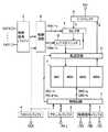
図1は、この発明の一実施の形態による同期型SRAMの全体構成を示すブロック図である。図1において、この同期型SRAMは、制御信号バッファ1,2、アドレスバッファ3、クロックバッファ4、制御回路5,6、メモリアレイ7、IOバッファ8、セレクタ9、レジスタユニット10、および転送回路11を備える。
【0010】
制御信号バッファ1は、外部制御信号/CS,/WE,/OEを制御回路5に伝達する。制御信号バッファ2は、外部制御信号CNT0〜CNTi(但し、iは0以上の整数である)を制御回路6に伝達する。アドレスバッファ3は、外部アドレス信号A0〜Aj(但し、jは0以上の整数である)を制御回路5に伝達する。クロックバッファ4は、外部クロック信号CLKをSRAM全体に供給する。
【0011】
制御回路5は、制御信号バッファ1、アドレスバッファ3およびクロックバッファ4を介して与えられた信号/CS,/WE,/OE,…に従って、行アドレス信号RA0〜RAa、列アドレス信号CA0〜CAb(但し、a,bの各々は0以上の整数である)、転送制御信号PD1〜PD4,PD1d〜PD4dなどの種々の内部信号を生成し、それらの内部信号によってSRAM全体を制御する。
【0012】
制御回路6は、制御信号バッファ2を介して与えられた信号CNT0〜CNTiに従ってテストモード信号TMA1〜TMAc,TMB1〜TMBc(但し、cは1以上の整数である)を生成し、それらの信号TMA1〜TMAc,TMB1〜TMBcをそれぞれセレクタ9およびレジスタユニット10に与える。
【0013】
メモリアレイ7は、4つのメモリブロックMB1〜MB4に分割されている。メモリブロックMB1〜MB4の各々は、複数行複数列に配置された複数のメモリセルを含む。各メモリセルは、1つのデータ信号を記憶する。
【0014】
IOバッファ8は、メモリアレイ7から転送回路11を介して与えられた読出データ信号Qを外部に出力するとともに、外部から与えられた書込データ信号Dをセレクタ9に与える。セレクタ9は、テストモード時は、制御回路6からの信号TMA1〜TMAcによって制御され、IOバッファ8を介して与えられた書込データ信号Dをレジスタユニット10に与える。またセレクタ9は、通常動作時は、IOバッファ8からの書込データ信号Dを転送回路11に与える。
【0015】
レジスタユニット10は、テストモード時において、制御回路6からの信号TMB1〜TMBcによって制御され、テスト用の書込データ信号Dを転送回路11に出力する。
【0016】
転送回路11は、書込動作時は、制御回路5からの信号PD1〜PD4に従って、メモリアレイ7の4つのメモリブロックMB1〜MB4のうちのいずれかのメモリブロックを選択し、セレクタ9またはレジスタユニット10からの書込データ信号Dを選択したメモリブロックに与える。また、転送回路11は、読出動作時は、制御回路5からの信号PD1d〜PD4dに従ってメモリアレイ7の4つのメモリブロックMB1〜MB4のうちのいずれかのメモリブロックを選択し、選択したメモリブロックとIOバッファ8とを結合する。転送回路11は、テストモード時にデータ信号の書込と読出を並行に行なう。転送回路11のテストモード時の動作については後に詳述する。
【0017】
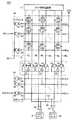
図2は、メモリブロックMB1の構成を示す回路ブロック図である。図2において、このメモリブロックMB1は、(n+1)行(m+1)列(但し、n,mの各々は1以上の整数である)に配置された(n+1)×(m+1)個のメモリセルMCと、それぞれn+1行に対応して設けられたワード線WL0〜WLnと、それぞれm+1列に対応して設けられたm+1組のビット線対BL,/BLと、それぞれm+1列に対応して設けられたm+1本の列選択線CL0〜CLmと、データ入出力線対IO,/IOとを含む。
【0018】
メモリセルMCは、図3に示すように、PチャネルMOSトランジスタ31,32およびNチャネルMOSトランジスタ33〜36を含む。PチャネルMOSトランジスタ31,32は、それぞれ電源電位VCCのラインと記憶ノードN1,N2との間に接続され、それらのゲートはそれぞれ記憶ノードN2,N1に接続される。NチャネルMOSトランジスタ33,34は、それぞれ記憶ノードN1,N2と接地電位GNDとのラインに接続され、それらのゲートはそれぞれ記憶ノードN2,N1に接続される。
【0019】
MOSトランジスタ32,34は、記憶ノードN1の信号の反転信号を記憶ノードN2に与える第1のインバータを構成する。MOSトランジスタ31,33は、記憶ノードN2の信号の反転信号を記憶ノードN1に与える第2のインバータを構成する。第1および第2のインバータは、記憶ノードN1,N2の信号を保持するラッチ回路を構成する。NチャネルMOSトランジスタ35はビット線BLと記憶ノードN1との間に接続され、NチャネルMOSトランジスタ36はビット線/BLと記憶ノードN2との間に接続され、NチャネルMOSトランジスタ35,36のゲートはワード線WLに接続される。
【0020】
書込動作時は、ワード線WLが「H」レベルに立上げられてNチャネルMOSトランジスタ35,36が導通する。次いで、書込データ信号Dに従ってビット線BL,/BLのうちのいずれか一方のビット線が「H」レベルにされるとともに他方のビット線が「L」レベルにされて、記憶ノードN1,N2の各々に信号が書込まれる。たとえば、データ信号Dが「H」レベル(1)の場合は記憶ノードN1,N2にそれぞれ「H」レベルおよび「L」レベルが書込まれ、データ信号Dが「L」レベル(0)の場合は記憶ノードN1,N2にそれぞれ「L」レベルおよび「H」レベルが書込まれる。ワード線WLが「L」レベルに立下げられると、NチャネルMOSトランジスタ35,36が非導通になり、記憶ノードN1,N2の信号がMOSトランジスタ31〜34によってラッチされる。
【0021】
読出動作時は、ビット線BL,/BLが「H」レベルにプリチャージされた後、ワード線WLが「H」レベルに立上げられる。ワード線WLが「H」レベルに立上げられると、NチャネルMOSトランジスタ35,36が導通し、メモリセルMCの記憶データに応じてビット線BL,/BLのうちのいずれか一方のビット線が「L」レベルに立下げられる。たとえば、記憶ノードN1,N2がそれぞれ「H」レベルおよび「L」レベルの場合は、ビット線/BLからNチャネルMOSトランジスタ36,34を介して接地電位GNDのラインに電流が流出し、ビット線/BLは「L」レベルにされる。一方、ビット線BLの電位は、NチャネルMOSトランジスタ33が非導通になっているので低下しない。したがって、ビット線BLと/BLの電位を比較することにより、メモリセルMCからデータ信号を読出すことができる。ワード線WLが「L」レベルに立上げられて、読出動作が終了する。
【0022】
各ビット線対BL,/BLの一方端はビット線周辺回路12に接続され、各ビット線対BL,/BLの他方端は列選択ゲート13に接続される。ビット線周辺回路12は、図3に示すように、各ビット線対BL,/BLに対応して設けられたNチャネルMOSトランジスタ37,38およびPチャネルMOSトランジスタ39を含む。NチャネルMOSトランジスタ37,38は、それぞれ電源電位VCCのラインとビット線BL,/BLの一方端との間にダイオード接続され、それぞれビット線BL,/BLを「H」レベルに充電する。PチャネルMOSトランジスタ39は、ビット線BLと/BLの間に接続され、そのゲートはビット線イコライズ信号/BLEQを受ける。信号/BLEQが活性化レベルの「L」レベルに立下げられると、PチャネルMOSトランジスタ39が導通し、ビット線BLと/BLの電位がイコライズされる。
【0023】
列選択ゲート13は、図2に示すように、各ビット線BL,/BLに対応して設けられたトランスファゲート14,15およびインバータ16を含む。トランスファゲート14はビット線BLの他方端とデータ入出力線IOとの間に接続され、トランスファゲート15はビット線/BLの他方端とデータ入出力線/IOとの間に接続される。列選択線CLは、対応のトランスファゲート14,15のNチャネルMOSトランジスタ側のゲートに直接接続されるとともに、対応のインバータ16を介して対応のトランスファゲート14,15のPチャネルMOSトランジスタ側のゲートに接続される。m+1本の列選択線CL0〜CLnのうちのいずれかの列選択線CLが選択レベルの「H」レベルに立上げられると、その列選択線CLに対応するトランスファゲート14,15が導通し、その列選択線CLに対応するビット線対BL./BLとデータ入出力線対IO,/IOとが結合される。
【0024】
行デコーダ20は、制御回路5からの行アドレス信号RA0〜RAaに従って、n+1本のワード線WL0〜WLnのうちのいずれかのワード線WLを選択し、選択したワード線WLを選択レベルの「H」レベルにする。すなわち行デコーダ20は、各ワード線WLに対応した設けられたNANDゲート21およびインバータ22を含む。各ワード線WLには、予め固有の行アドレス信号RA0〜RAaが割当てられている。NANDゲート21およびインバータ22は、予め割当てられた行アドレス信号RA0〜RAaが入力され、かつブロック選択信号BS1が選択レベルの「H」レベルにされたことに応じて対応のワード線WLを選択レベルの「H」レベルに立上げる。ブロック選択信号BS1は、アドレス信号A0〜AjによってメモリブロックMB1が指定された場合に選択レベルの「H」レベルにされる信号である。
【0025】
列デコーダ23は、制御回路5からの列アドレス信号CA0〜CAaに従って、m+1本の列選択線CL0〜CLmのうちのいずれかの列選択線CLを選択し、選択した列選択線CLを選択レベルの「H」レベルにする。すなわち列デコーダ23は、各列選択線CLに対応して設けられたNANDゲート24およびインバータ25を含む。各列選択線CLには、予め固有の列アドレス信号CA0〜CAbが割当てられている。NANDゲート24およびインバータ25は、予め割当てられた列アドレス信号CA0〜CAbが入力されたことに応じて対応の列選択線CLを選択レベルの「H」レベルに立上げる。
【0026】
ライトドライバ26は、書込動作時に、書込データ信号Dに従って、データ入出力線IO,/IOのうちのいずれか一方のデータ入出力線を「H」レベルにするとともに他方のデータ入出力線を「L」レベルにする。センスアンプ27は、読出動作時に、データ入出力線IOと/IOの電位を比較し、比較結果に応じた論理レベルのデータ信号Qを出力する。
【0027】
次に、図2および図3に示したメモリブロックMB1の動作について説明する。但し、メモリブロックMB1が選択されてブロック選択信号BS1が選択レベルの「H」レベルにされているものとする。書込動作時は、行アドレス信号RA0〜RAaによって指定された行のワード線WLが行デコーダ20によって選択レベルの「H」レベルに立上げられ、その行の各メモリセルMCが活性化される。次いで、列アドレス信号CA0〜CAbによって指定された列の列選択線CLが列デコーダ23によって選択レベルの「H」レベルに立上げられ、その列のトランスファゲート14,15が導通し、活性化された1つのメモリセルMCがビット線対BL,/BLおよびデータ入出力線対IO,/IOを介してライトドライバ26に接続される。
【0028】
ライトドライバ26は、書込データ信号Dに従って、データ入出力線IO,/IOのうちのいずれか一方のデータ入出力線を「H」レベルにするとともに他方のデータ入出力線を「L」レベルにしてメモリセルMCにデータを書込む。ワード線WLおよび列選択線CLが「L」レベルに立下げられると、メモリセルMCにデータが記憶される。
【0029】
読出動作時は、列アドレス信号CA0〜CAbによって指定された列の列選択線CLが選択レベルの「H」レベルに立上げられ、その列のトランスファゲート14,15が導通してビット線BL,/BLがデータ入出力線対IO,/IOを介してセンスアンプ27に接続される。次いで、ビット線イコライズ信号/BLEQが活性化レベルの「L」レベルにされて各PチャネルMOSトランジスタ39が導通し、ビット線BL,/BLの電位がイコライズされる。
【0030】
ビット線イコライズ信号/BLEQが非活性化レベルの「H」レベルになり、各PチャネルMOSトランジスタ39が非導通になった後、行アドレス信号RA0〜RAaに応じた行のワード線WLが行デコーダ20によって選択レベルの「H」レベルに立上げられ、その行の各メモリセルMCが活性化される。これにより、メモリセルMCの記憶データに応じてビット線BL,/BLのうちのいずれか一方のビット線からメモリセルMCに電流が流入し、これに応じてデータ入出力線IO,/IOのうちの一方のデータ入出力線の電位が低下する。センスアンプ27は、データ入出力線IOと/IOの電位を比較し、比較結果に応じた論理レベルのデータ信号Qを出力する。
【0031】
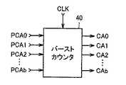
データ信号の書込/読出を連続的に行なうバースト動作時は、複数(たとえば4つ)の列選択線が1クロックサイクルずつ順次「H」レベルにされる。この場合、2つ目以降の列アドレス信号CA0〜CAbは、制御回路5内で生成される。すなわち制御回路5内には、図4に示すように、バーストカウンタ40が設けられている。バーストカウンタ40は、外部アドレス信号A0〜Ajに基づいて生成された内部列アドレス信号PCA0〜PCAbをラッチし、1つ目の列アドレス信号CA0〜CAbとして出力する。バーストカウンタ40は、クロック信号CLKのパルス数をカウントし、出力列アドレス信号CA0〜CAbの値をインクリメント(+1)する。これにより、連続する4つの列アドレス信号CA0〜CAbが生成されて4つの列選択線が順次選択され、4つのメモリセルMCへのデータ信号の書込/読出が順次行なわれる。
【0032】
図5は、転送回路11の構成を示す回路ブロック図である。図5において、転送回路11は、ライトゲート41〜44、リードゲート45〜48、バッファ49、ライトデータ線WDLおよびリードデータ線RDLを含む。バッファ49は、セレクタ9またはレジスタユニット10からの書込データ信号Dをライトデータ線WDLに与える。ライトゲート41〜44は、それぞれライトデータ線WDLとメモリブロックMB1〜MB4のライトドライバ26との間に設けられ、それぞれ信号PD1〜PD4が活性化の「H」レベルにされたことに応じて導通状態になる。ライトゲート41〜44が導通状態になった場合は、それぞれデータ信号DがメモリブロックMB1〜MB4のライトドライバ26に与えられる。
【0033】
リードゲート45〜48は、それぞれメモリブロックMB1〜MB4のセンスアンプ27とリードデータ線RDLとの間に設けられ、それぞれ信号PD1d〜PD4dが活性化レベルの「H」レベルにされたことに応じて導通状態になる。リードゲート45〜48が導通状態になった場合は、それぞれメモリブロックMB1〜MB4のセンスアンプ27からリードデータ線RDLに読出データ信号Qが与えられる。リードデータ線RDLはIOバッファ8に接続される。
【0034】
図6は、制御回路5のうちの転送制御信号PD1〜PD4,PD1d〜PD4dの生成に関連する部分を示すブロック図である。図6において、制御回路5は、ブロック選択デコーダ51、遅延回路52およびバーストカウンタ53を含む。ブロック選択デコーダ51は、テストモード信号TMが非活性化レベルの「L」レベルの場合すなわち通常動作時に活性化され、アドレス信号A0,A1に従って転送制御信号PD1〜PD4のうちのいずれかの信号を選択し、選択した信号を所定のタイミングで選択レベルの「H」レベルにする。バーストカウンタ53は、テストモード信号TMが活性化レベルの「H」レベルの場合すなわちテストモード時に活性化され、図7に示すように、クロック信号CLKに同期して信号PD1〜PD4を1/2サイクルずつ「H」レベルにする。遅延回路52は、信号PD1〜PD4を1サイクル分だけ遅延させて信号PD1d〜PD4dを生成する。
【0035】
たとえば、サイクル1では、信号PD1が「H」レベルになり、ライトゲート41が導通してメモリブロックMB1のメモリセルMCにデータ信号Dが書込まれる。サイクル2では、信号PD1d,PD2が「H」レベルになり、リードゲート45が導通してメモリブロックMB1の読出データ信号Qがリードデータ線RDLに与えられるとともに、ライトゲート42が導通してメモリブロックMB2のメモリセルMCにデータ信号Dが書込まれる。
【0036】
サイクル3では、信号PD2d,PD3が「H」レベルになり、リードゲート46が導通してメモリブロックMB2の読出データ信号Qがリードデータ線RDLに与えられるとともに、ライトゲート43が導通してメモリブロックMB3のメモリセルMCにデータ信号Dが書込まれる。
【0037】
サイクル4では、信号PD3d,PD4が「H」レベルになり、リードゲート47が導通してメモリブロックMB3の読出データ信号Qがリードデータ線RDLに与えられるとともに、ライトゲート44が導通してメモリブロックMB4のメモリセルMCにデータ信号Dが書込まれる。
【0038】
サイクル5では、信号PD4d,PD1が「H」レベルになり、リードゲート48が導通してメモリブロックMB4の読出データ信号Qがリードデータ線RDLに与えられるとともに、ライトゲート41が導通してメモリブロックMB1のメモリセルMCにデータ信号Dが書込まれる。
【0039】
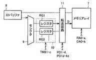
以下、このSRAMのテストモード時の動作について説明する。SRAMは、テスタ(図示せず)に接続される。まずテスタは、図8および図9に示すように、レジスタユニット10内の複数のレジスタRG1〜RGcのうちの所望のレジスタ(たとえばRG1)にバースト長(4とする)分のテストデータ信号D0〜D3を書込む。すなわち、テスタは、テストモード信号TMA1〜TMAcのうちのレジスタRG1に対応するテストモード信号TMA1を活性化させる。活性化された信号TMA1は、クロック信号CLKの遅延信号となり、クロック信号CLKの立上がりエッジで「H」レベルになる。次いでテスタは、クロック信号CLKのある立上がりエッジ(時刻t1)に同期して信号/WEを「L」レベルにするとともに最初のデータ信号D0を入力し、次いで3つのデータ信号D1〜D3をクロック信号CLKの立上がりエッジに同期して順次入力する。これにより、テストデータ信号D0〜D3は、IOバッファ8およびセレクタ9を介してレジスタRG1に書込まれる。
【0040】
次にテスタは、図10〜図12に示すように、レジスタRG1内のデータ信号D0〜D3をメモリアレイ7内の複数のメモリセルMCにバースト書込みさせるとともに、データ信号D0〜D3が書込まれた複数のメモリセルMCからデータ信号Q0〜Q3をバースト読出しさせる。すなわち、テスタは、テストモード信号TMB1〜TMBcのうちの所望のレジスタRG1に対応するテストモード信号TMB1を活性化させる。活性化された信号TMB1は、クロック信号CLKの遅延信号となり、クロック信号CLKの立上がりエッジで「H」レベルになる。次いでテスタは、クロック信号CLKのある立上がりエッジ(時刻t0)に同期してスタートアドレス信号A(0,0)(図2の0行0列のメモリセルMCを指定するアドレス信号)を入力するとともに、信号/WEを「L」レベルにする。また、図6および図7で示したように、サイクル1ではメモリブロックMB1用のライトゲート41が導通し、レジスタRG1の出力データ信号D0はメモリブロックMB1のアドレス信号A(0,0)で指定されるメモリセルMCに書込まれる。このときのライトレイテンシは、1サイクルである。
【0041】
クロック信号CLKの次の立上がりエッジ(時刻t1)では、図4のバーストカウンタ40により、アドレス信号A(0,0)をインクリメントしたアドレス信号A(0,1)(図2の0行1列のメモリセルMCを指定するアドレス信号)が生成される。また、図6および図7で示したように、サイクル2ではメモリブロックMB1用のリードゲート45が導通するとともにメモリブロックMB2用のライトゲート42が導通し、メモリブロックMB1のアドレス信号A(0,0)で指定されるメモリセルMCのデータ信号Q0が読出されるとともにメモリブロックMB2のアドレス信号A(0,1)で指定されるメモリセルMCにデータ信号D1が書込まれる。
【0042】
以下同様にして、サイクル3では、メモリブロックMB2のアドレス信号A(0,1)で指定されるメモリセルMCからデータ信号Q1が読出されるとともに、メモリブロックMB3のアドレス信号A(0,2)で指定されるメモリセルMCにデータ信号D2が書込まれる。
【0043】
サイクル4では、メモリブロックMB3のアドレス信号A(0,2)で指定されるメモリセルMCからデータ信号Q2が読出されるとともに、メモリブロックMB4のアドレス信号A(0,3)で指定されるメモリセルMCにデータ信号D3が書込まれる。
【0044】
またサイクル4では、次のスタートアドレス信号A(1,0)が入力され、サイクル5ではメモリブロックMB4のアドレス信号A(0,3)で指定されるメモリセルMCからデータ信号Q3が読出されるとともに、メモリブロックMB1のアドレス信号A(1,0)で指定されるメモリセルMCにデータ信号D0が書込まれる。以下同様にして、すべてのメモリセルMCのデータ信号の書込/読出が行なわれる。
【0045】
メモリセルMCの読出データ信号Qの論理レベルが期待値(そのメモリセルMCに書込んだデータ信号Dの論理レベル)と一致した場合は、そのメモリセルMCは正常であると判定される。メモリセルMCの読出データ信号Qの論理レベルが期待値と一致しない場合は、そのメモリセルMCは不良であると判定され、そのメモリセルMCのアドレス信号がテスタに記憶される。
【0046】
不良なメモリセルMCはスペアメモリセル(図示せず)と置換される。スペアメモリセルで不良なメモリセルMCを置換できない場合は、そのSRAMは廃棄される。
【0047】
この実施の形態では、書込用のデータ信号D0〜D3はレジスタRGから出力されるので、書込用のデータ信号をテスタから別途与える必要はない。また、1つのアドレス信号A0〜Ajに応答して4つのメモリセルMCを選択し、選択したメモリセルMCのデータ信号の書込/読出を行なうので、入力するアドレス信号A0〜Ajの数が少なくて済む。したがって、テストの簡単化を図ることができる。
【0048】
また、テストモード時に、データ信号の書込と読出を並行に行なうので、すべてのメモリセルMCにデータ信号を書込んだ後に各メモリセルMCのデータ信号の読出を行なっていた従来に比べ、テスト時間の短縮化を図ることができる。
【0049】
なお、この実施の形態では、1つのレジスタRG1のみを使用したが、複数のレジスタRG1〜RGcに互いに異なるパターンのデータ信号D0〜D3を格納しておき、レジスタRG1〜RGcを適宜切換えて使用してもよい。この場合、より複雑なテストパターンをメモリアレイ7に書込むことができる。
【0050】
今回開示された実施の形態はすべての点で例示であって制限的なものではないと考えられるべきである。本発明の範囲は上記した説明ではなくて特許請求の範囲によって示され、特許請求の範囲と均等の意味および範囲内でのすべての変更が含まれることが意図される。
【0051】
【発明の効果】
以上のように、この発明に係る半導体記憶装置では、複数のメモリセルと、各メモリセルが正常か否かをテストするテストモード時に、予め書込まれたN個(但し、Nは2以上の整数である)のデータ信号を1つずつ順次出力するレジスタと、アドレス信号に従って、複数のメモリセルのうちのいずれかN個のメモリセルを1つずつ順次選択するデコーダと、レジスタから出力されるN個のデータ信号をそれぞれデコーダによって選択されるN個のメモリセルに順次書込む書込回路と、書込回路よりもM(但し、Mは1以上N−1以下の整数である)クロックサイクルだけ遅延して動作し、デコーダによって選択されるN個のメモリセルのデータ信号を順次読出す読出回路とが設けられる。したがって、書込用のデータ信号はレジスタから出力されるので、外部から書込用のデータ信号を別途与える必要がない。また、1つのアドレス信号に応答してN個のメモリセルを選択し、選択したメモリセルのデータ信号の書込/読出を行なうので、入力するアドレス信号の数が少なくて済む。したがって、テストの簡単化を図ることができる。
【0052】
また、この発明に係るテスト方法では、上記半導体記憶装置を活性化させてテストモードに設定し、デコーダにアドレス信号を与え、読出回路によって読出されるデータ信号に基づいて各メモリセルが正常か否かを判定する。したがって、アドレス信号を与え、読出データ信号を期待値と比較するだけで半導体記憶装置をテストすることができ、テスト動作の簡単化を図ることができる。
【図面の簡単な説明】
【図1】この発明の一実施の形態による同期型SRAMの全体構成を示すブロック図である。
【図2】図1に示したメモリブロックの構成を示す回路ブロック図である。
【図3】図2に示したメモリセルおよびビット線周辺回路の構成を示す回路図である。
【図4】図1に示した制御回路5に含まれるバーストカウンタを示すブロック図である。
【図5】図1に示した転送回路の構成を示す回路ブロック図である。
【図6】図5に示した転送制御信号の生成に関連する部分の構成を示すブロック図である。
【図7】図6に示したバーストカウンタおよび遅延回路の動作を示すタイムチャートである。
【図8】図1〜図7に示したSRAMのテストモード時の動作を説明するためのブロック図である。
【図9】図8で説明したテストモード時の動作を示すタイムチャートである。
【図10】図1〜図7で示したSRAMのテストモード時の動作を説明するためのブロック図である。
【図11】図1〜図7で示したSRAMのテストモード時の動作を説明するための他のブロック図である。
【図12】図10および図11で説明したテストモード時の動作を示すタイムチャートである。
【符号の説明】
1,2 制御信号バッファ、3 アドレスバッファ、4 クロックバッファ、5,6 制御回路、7 メモリアレイ、MB メモリブロック、8 IOバッファ、9 セレクタ、10 レジスタユニット、11 転送回路、MC メモリセル、WL ワード線、BL,/BL ビット線対、12 ビット線周辺回路、13 列選択ゲート、14,15 トランスファゲート、16,22,25 インバータ、20 行デコーダ、21,24 NANDゲート、23 列デコーダ、26 ライトドライバ、27 センスアンプ、31,32,39 PチャネルMOSトランジスタ、33〜38 NチャネルMOSトランジスタ、40,53 バーストカウンタ、41〜44 ライトゲート、45〜48 リードゲート、49 バッファ、51 ブロック選択デコーダ、52 遅延回路、RG レジスタ。[0001]
TECHNICAL FIELD OF THE INVENTION
The present invention relates to a semiconductor memory device and a test method therefor, and more particularly, to a semiconductor memory device having a test mode for testing whether each memory cell is normal and operating in synchronization with a clock signal and a test method therefor.
[0002]
[Prior art]
2. Description of the Related Art Conventionally, in semiconductor storage devices such as SRAMs and DRAMs, a test for determining whether or not each memory cell is normal is performed before shipment. In this test, predetermined data is written to each of a plurality of memory cells included in a memory array, and then data of each memory cell is read. If the logic of the data read from each memory cell matches the logic of the data written to the memory cell, the memory cell is determined to be normal; otherwise, the memory cell is defective. Is determined. Defective memory cells are replaced with spare memory cells.
[0003]
There has also been a test method in which writing of external data to each memory cell and reading of data from other memory cells are performed in parallel (for example, see Patent Document 1).
[0004]
[Patent Document 1]
JP-A-59-175100
[0005]
[Problems to be solved by the invention]
However, in the conventional test method, it is necessary to write the data signal by supplying an address signal and a data signal from the tester to the semiconductor memory device, and to read the data signal by supplying the address signal from the tester to the semiconductor memory device. Therefore, there was a problem that the test operation became complicated.
[0006]
Therefore, a main object of the present invention is to provide a semiconductor memory device capable of easily testing whether or not each memory cell is normal and a test method thereof.
[0007]
[Means for Solving the Problems]
A semiconductor memory device according to the present invention is a semiconductor memory device that operates in synchronization with a clock signal, and is programmed in advance in a test mode for testing a plurality of memory cells and whether each memory cell is normal. A register for sequentially outputting N data signals (where N is an integer of 2 or more) one by one, and one of N memory cells among a plurality of memory cells sequentially one by one according to an address signal A decoder for selecting, a write circuit for sequentially writing N data signals output from the register into N memory cells selected by the decoder, and M (where M is 1 or more and N A read circuit that operates with a delay of clock cycles (an integer of -1 or less) and sequentially reads the data signals of the N memory cells selected by the decoder.
[0008]
Further, according to the test method of the present invention, the semiconductor memory device is activated to set a test mode, an address signal is supplied to a decoder, and whether or not each memory cell is normal based on a data signal read by a read circuit. Is determined.
[0009]
BEST MODE FOR CARRYING OUT THE INVENTION
FIG. 1 is a block diagram showing an overall configuration of a synchronous SRAM according to an embodiment of the present invention. 1, the synchronous SRAM includes
[0010]
[0011]
[0012]
The
[0013]
The
[0014]
[0015]
Register
[0016]
During a write operation, the
[0017]
FIG. 2 is a circuit block diagram showing a configuration of the memory block MB1. In FIG. 2, this memory block MB1 has (n + 1) × (m + 1) memory cells MC arranged in (n + 1) rows and (m + 1) columns (where n and m are each an integer of 1 or more). , Word lines WL0 to WLn provided corresponding to n + 1 rows, m + 1 pairs of bit lines BL and / BL provided corresponding to m + 1 columns, respectively, and provided corresponding to m + 1 columns. M + 1 column select lines CL0 to CLm and a data input / output line pair IO, / IO.
[0018]
Memory cell MC includes P-
[0019]
[0020]
During a write operation, word line WL is raised to "H" level, and N-
[0021]
In the read operation, after the bit lines BL and / BL are precharged to "H" level, the word line WL is raised to "H" level. When word line WL is raised to "H" level, N-
[0022]
One end of each bit line pair BL, / BL is connected to bit line
[0023]
As shown in FIG. 2, column
[0024]
The
[0025]
The
[0026]
During a write operation, write
[0027]
Next, the operation of the memory block MB1 shown in FIGS. 2 and 3 will be described. However, it is assumed that the memory block MB1 is selected and the block selection signal BS1 is set to the “H” level of the selection level. At the time of a write operation, word line WL of a row designated by row address signals RA0 to RAa is raised to a selected level "H" by
[0028]
Write
[0029]
At the time of the read operation, the column selection line CL of the column specified by the column address signals CA0 to CAb is raised to the selected level of "H" level, and the
[0030]
After bit line equalize signal / BLEQ attains the "H" level of the inactivation level and each P-
[0031]
In a burst operation for continuously writing / reading data signals, a plurality (for example, four) of column select lines are sequentially set to "H" level one clock cycle at a time. In this case, the second and subsequent column address signals CA0 to CAb are generated in the
[0032]
FIG. 5 is a circuit block diagram showing a configuration of the
[0033]
Read
[0034]
FIG. 6 is a block diagram showing a part of the
[0035]
For example, in
[0036]
In
[0037]
In
[0038]
In
[0039]
The operation of the SRAM in the test mode will be described below. The SRAM is connected to a tester (not shown). First, as shown in FIGS. 8 and 9, the tester applies test data signals D0 to burst registers (for example, RG1) of a plurality of registers RG1 to RGc in
[0040]
Next, the tester burst-writes the data signals D0 to D3 in the register RG1 to the plurality of memory cells MC in the
[0041]
At the next rising edge (time t1) of clock signal CLK, address signal A (0,1) obtained by incrementing address signal A (0,0) by
[0042]
Similarly, in
[0043]
In
[0044]
In
[0045]
If the logic level of the read data signal Q of the memory cell MC matches the expected value (the logic level of the data signal D written in the memory cell MC), it is determined that the memory cell MC is normal. When the logic level of the read data signal Q of the memory cell MC does not match the expected value, the memory cell MC is determined to be defective, and the address signal of the memory cell MC is stored in the tester.
[0046]
The defective memory cell MC is replaced with a spare memory cell (not shown). If the defective memory cell MC cannot be replaced with a spare memory cell, the SRAM is discarded.
[0047]
In this embodiment, since the write data signals D0 to D3 are output from the register RG, it is not necessary to separately provide the write data signal from the tester. Further, four memory cells MC are selected in response to one address signal A0-Aj, and the data signal of the selected memory cell MC is written / read, so that the number of input address signals A0-Aj is small. Do it. Therefore, the test can be simplified.
[0048]
Further, in the test mode, writing and reading of data signals are performed in parallel, so that the data signal is written to all memory cells MC and then the data signal of each memory cell MC is read, compared to the conventional method. Time can be reduced.
[0049]
In this embodiment, only one register RG1 is used. However, data signals D0 to D3 having different patterns are stored in a plurality of registers RG1 to RGc, and the registers RG1 to RGc are appropriately switched and used. You may. In this case, a more complicated test pattern can be written in the
[0050]
The embodiments disclosed this time are to be considered in all respects as illustrative and not restrictive. The scope of the present invention is defined by the terms of the claims, rather than the description above, and is intended to include any modifications within the scope and meaning equivalent to the terms of the claims.
[0051]
【The invention's effect】
As described above, in the semiconductor memory device according to the present invention, a plurality of memory cells and, in a test mode for testing whether or not each memory cell is normal, N pieces of data written in advance (where N is 2 or more) A data signal that is an integer), a decoder that sequentially selects one of the N memory cells among the plurality of memory cells one by one according to the address signal, and a register that outputs the data signal. A write circuit for sequentially writing N data signals into N memory cells selected by a decoder, and M (where M is an integer from 1 to N-1) clock cycles more than the write circuit And a read circuit which operates with only a delay and sequentially reads the data signals of the N memory cells selected by the decoder. Therefore, since the write data signal is output from the register, it is not necessary to separately provide an external write data signal. Further, N memory cells are selected in response to one address signal, and writing / reading of data signals of the selected memory cell is performed, so that the number of input address signals can be reduced. Therefore, the test can be simplified.
[0052]
Further, in the test method according to the present invention, the semiconductor memory device is activated and set to a test mode, an address signal is supplied to a decoder, and each memory cell is determined to be normal based on a data signal read by a read circuit. Is determined. Therefore, a semiconductor memory device can be tested only by applying an address signal and comparing a read data signal with an expected value, and the test operation can be simplified.
[Brief description of the drawings]
FIG. 1 is a block diagram showing an overall configuration of a synchronous SRAM according to an embodiment of the present invention.
FIG. 2 is a circuit block diagram showing a configuration of a memory block shown in FIG.
FIG. 3 is a circuit diagram showing a configuration of a memory cell and a bit line peripheral circuit shown in FIG. 2;
FIG. 4 is a block diagram showing a burst counter included in a
FIG. 5 is a circuit block diagram showing a configuration of a transfer circuit shown in FIG.
FIG. 6 is a block diagram illustrating a configuration of a portion related to generation of a transfer control signal illustrated in FIG. 5;
FIG. 7 is a time chart illustrating operations of the burst counter and the delay circuit illustrated in FIG. 6;
FIG. 8 is a block diagram for explaining an operation of the SRAM shown in FIGS. 1 to 7 in a test mode;
FIG. 9 is a time chart showing an operation in the test mode described in FIG. 8;
FIG. 10 is a block diagram for describing an operation of the SRAM shown in FIGS. 1 to 7 in a test mode.
FIG. 11 is another block diagram for describing an operation of the SRAM shown in FIGS. 1 to 7 in a test mode.
FIG. 12 is a time chart showing the operation in the test mode described with reference to FIGS. 10 and 11;
[Explanation of symbols]
1, 2 control signal buffer, 3 address buffer, 4 clock buffer, 5, 6 control circuit, 7 memory array, MB memory block, 8 IO buffer, 9 selector, 10 register unit, 11 transfer circuit, MC memory cell, WL word Line, BL, / BL bit line pair, 12 bit line peripheral circuit, 13 column select gate, 14, 15 transfer gate, 16, 22, 25 inverter, 20 row decoder, 21, 24 NAND gate, 23 column decoder, 26 write Driver, 27 sense amplifier, 31, 32, 39 P-channel MOS transistor, 33-38 N-channel MOS transistor, 40, 53 burst counter, 41-44 write gate, 45-48 read gate, 49 buffer, 51 block selection decoder, 52 delay circuit, R Register.
Claims (5)
Translated fromJapanese複数のメモリセル、
各メモリセルが正常か否かをテストするテストモード時に、予め書込まれたN個(但し、Nは2以上の整数である)のデータ信号を1つずつ順次出力するレジスタ、
アドレス信号に従って、前記複数のメモリセルのうちのいずれかN個のメモリセルを1つずつ順次選択するデコーダ、
前記レジスタから出力されるN個のデータ信号をそれぞれ前記デコーダによって選択されるN個のメモリセルに順次書込む書込回路、および
前記書込回路よりもM(但し、Mは1以上N−1以下の整数である)クロックサイクルだけ遅延して動作し、前記デコーダによって選択されるN個のメモリセルのデータ信号を順次読出す読出回路を備える、半導体記憶装置。A semiconductor memory device that operates in synchronization with a clock signal,
Multiple memory cells,
A register for sequentially outputting N (where N is an integer of 2 or more) pre-written data signals one by one in a test mode for testing whether or not each memory cell is normal;
A decoder for sequentially selecting one of the N memory cells among the plurality of memory cells one by one according to an address signal;
A write circuit for sequentially writing N data signals output from the register into N memory cells selected by the decoder, and M (where M is 1 or more and N-1) A semiconductor memory device comprising: a read circuit that operates with a delay of a clock cycle (the following integer) and sequentially reads data signals of N memory cells selected by the decoder.
前記デコーダは、前記アドレス信号に従って、前記N個のメモリブロックからメモリセルを1つずつ順次選択する、請求項1または請求項2に記載の半導体記憶装置。The plurality of memory cells are divided into N memory blocks each including a plurality of memory cells,
3. The semiconductor memory device according to claim 1, wherein said decoder sequentially selects memory cells one by one from said N memory blocks according to said address signal.
さらに、選択信号に従って前記複数のレジスタのうちのいずれかのレジスタを選択し、選択したレジスタの出力データ信号を前記書込回路に与える選択回路を備える、請求項1から請求項3のいずれかに記載の半導体記憶装置。A plurality of registers are provided,
4. The circuit according to claim 1, further comprising: a selection circuit that selects one of the plurality of registers according to a selection signal and provides an output data signal of the selected register to the writing circuit. 5. 13. The semiconductor memory device according to claim 1.
前記半導体記憶装置を活性化させて前記テストモードに設定し、
前記デコーダに前記アドレス信号を与え、
前記読出回路によって読出されるデータ信号に基づいて各メモリセルが正常か否かを判定する、テスト方法。A test method for testing the semiconductor memory device according to claim 1, wherein:
Activating the semiconductor memory device and setting the test mode;
Providing the address signal to the decoder;
A test method for determining whether each memory cell is normal based on a data signal read by the read circuit.
Priority Applications (4)
| Application Number | Priority Date | Filing Date | Title |
|---|---|---|---|
| JP2002311297AJP4184036B2 (en) | 2002-10-25 | 2002-10-25 | Semiconductor memory device and test method thereof |
| US10/377,596US6873556B2 (en) | 2002-10-25 | 2003-03-04 | Semiconductor memory device with test mode and testing method thereof |
| TW092113848ATWI223264B (en) | 2002-10-25 | 2003-05-22 | Semiconductor memory device and testing method thereof |
| KR1020030034364AKR100543226B1 (en) | 2002-10-25 | 2003-05-29 | Semiconductor memory device with test mode |
Applications Claiming Priority (1)
| Application Number | Priority Date | Filing Date | Title |
|---|---|---|---|
| JP2002311297AJP4184036B2 (en) | 2002-10-25 | 2002-10-25 | Semiconductor memory device and test method thereof |
Publications (2)
| Publication Number | Publication Date |
|---|---|
| JP2004146001Atrue JP2004146001A (en) | 2004-05-20 |
| JP4184036B2 JP4184036B2 (en) | 2008-11-19 |
Family
ID=32105310
Family Applications (1)
| Application Number | Title | Priority Date | Filing Date |
|---|---|---|---|
| JP2002311297AExpired - Fee RelatedJP4184036B2 (en) | 2002-10-25 | 2002-10-25 | Semiconductor memory device and test method thereof |
Country Status (4)
| Country | Link |
|---|---|
| US (1) | US6873556B2 (en) |
| JP (1) | JP4184036B2 (en) |
| KR (1) | KR100543226B1 (en) |
| TW (1) | TWI223264B (en) |
Cited By (1)
| Publication number | Priority date | Publication date | Assignee | Title |
|---|---|---|---|---|
| JP2006165569A (en)* | 2004-12-07 | 2006-06-22 | Samsung Electronics Co Ltd | Analysis structure for failure analysis of semiconductor device and failure analysis method using the same |
Families Citing this family (5)
| Publication number | Priority date | Publication date | Assignee | Title |
|---|---|---|---|---|
| JP2005011451A (en)* | 2003-06-19 | 2005-01-13 | Advantest Corp | Test device and program |
| US7142442B1 (en) | 2004-03-08 | 2006-11-28 | Xilinx, Inc. | Segmented dataline scheme in a memory with enhanced full fault coverage memory cell testability |
| KR100640635B1 (en) | 2005-02-07 | 2006-10-31 | 삼성전자주식회사 | Semiconductor memory device that can be tested using various test data patterns |
| US20140133253A1 (en)* | 2012-11-13 | 2014-05-15 | Taiwan Semiconductor Manufacturing Company, Ltd. | System and Method for Memory Testing |
| KR102174337B1 (en) | 2014-04-08 | 2020-11-04 | 삼성전자주식회사 | Memory System and Electronic device including memory system |
Family Cites Families (3)
| Publication number | Priority date | Publication date | Assignee | Title |
|---|---|---|---|---|
| JPS59175100A (en) | 1983-03-24 | 1984-10-03 | Nec Corp | Data storing system |
| JPH0793997A (en)* | 1993-09-24 | 1995-04-07 | Nec Corp | Static semiconductor memory device |
| DE10124923B4 (en)* | 2001-05-21 | 2014-02-06 | Qimonda Ag | Test method for testing a data memory and data memory with integrated test data compression circuit |
- 2002
- 2002-10-25JPJP2002311297Apatent/JP4184036B2/ennot_activeExpired - Fee Related
- 2003
- 2003-03-04USUS10/377,596patent/US6873556B2/ennot_activeExpired - Fee Related
- 2003-05-22TWTW092113848Apatent/TWI223264B/ennot_activeIP Right Cessation
- 2003-05-29KRKR1020030034364Apatent/KR100543226B1/ennot_activeExpired - Fee Related
Cited By (1)
| Publication number | Priority date | Publication date | Assignee | Title |
|---|---|---|---|---|
| JP2006165569A (en)* | 2004-12-07 | 2006-06-22 | Samsung Electronics Co Ltd | Analysis structure for failure analysis of semiconductor device and failure analysis method using the same |
Also Published As
| Publication number | Publication date |
|---|---|
| KR100543226B1 (en) | 2006-01-20 |
| KR20040036523A (en) | 2004-04-30 |
| US6873556B2 (en) | 2005-03-29 |
| US20040081008A1 (en) | 2004-04-29 |
| JP4184036B2 (en) | 2008-11-19 |
| TWI223264B (en) | 2004-11-01 |
| TW200406764A (en) | 2004-05-01 |
Similar Documents
| Publication | Publication Date | Title |
|---|---|---|
| JP2012164416A (en) | Method and apparatus for synchronization of row and column access operations | |
| US7466623B2 (en) | Pseudo SRAM capable of operating in continuous burst mode and method of controlling burst mode operation thereof | |
| JP3752288B2 (en) | Semiconductor memory device | |
| EP2082399B1 (en) | Memory bus output driver of a multi-bank memory device and method therefor | |
| US7508706B2 (en) | Nonvolatile semiconductor memory device provided with data register for temporarily holding data in memory array | |
| US6789137B2 (en) | Semiconductor memory device allowing reduction of I/O terminals | |
| US6809975B2 (en) | Semiconductor memory device having test mode and memory system using the same | |
| KR100473747B1 (en) | Semiconductor memory device that operates in synchronization with a clock signal | |
| US6704238B2 (en) | Semiconductor memory device including data bus pairs respectively dedicated to data writing and data reading | |
| US7016235B2 (en) | Data sorting in memories | |
| US6785187B2 (en) | Semiconductor device having integrated memory and logic | |
| US5483488A (en) | Semiconductor static random access memory device capable of simultaneously carrying disturb test in a plurality of memory cell blocks | |
| JP4184036B2 (en) | Semiconductor memory device and test method thereof | |
| US6636455B2 (en) | Semiconductor memory device that operates in synchronization with a clock signal | |
| JP3992901B2 (en) | Synchronous DRAM semiconductor device having write interrupt write function | |
| JP2001243794A (en) | Semiconductor storage device | |
| JP2001067866A (en) | Synchronous semiconductor memory device | |
| JP5231190B2 (en) | Semiconductor devices and memory macros | |
| JP2004071119A (en) | Semiconductor memory device | |
| US6704229B2 (en) | Semiconductor test circuit for testing a semiconductor memory device having a write mask function | |
| US6590814B1 (en) | Semiconductor memory device and redundancy method thereof | |
| USRE40172E1 (en) | Multi-bank testing apparatus for a synchronous dram | |
| JP2003196985A (en) | Semiconductor memory, bit-write method or byte-write method for semiconductor memory | |
| TW201447330A (en) | Semiconductor device | |
| JP2004103119A (en) | Semiconductor memory device |
Legal Events
| Date | Code | Title | Description |
|---|---|---|---|
| A621 | Written request for application examination | Free format text:JAPANESE INTERMEDIATE CODE: A621 Effective date:20050404 | |
| TRDD | Decision of grant or rejection written | ||
| A01 | Written decision to grant a patent or to grant a registration (utility model) | Free format text:JAPANESE INTERMEDIATE CODE: A01 Effective date:20080826 | |
| A01 | Written decision to grant a patent or to grant a registration (utility model) | Free format text:JAPANESE INTERMEDIATE CODE: A01 | |
| A61 | First payment of annual fees (during grant procedure) | Free format text:JAPANESE INTERMEDIATE CODE: A61 Effective date:20080903 | |
| FPAY | Renewal fee payment (event date is renewal date of database) | Free format text:PAYMENT UNTIL: 20110912 Year of fee payment:3 | |
| R150 | Certificate of patent or registration of utility model | Free format text:JAPANESE INTERMEDIATE CODE: R150 | |
| FPAY | Renewal fee payment (event date is renewal date of database) | Free format text:PAYMENT UNTIL: 20110912 Year of fee payment:3 | |
| S111 | Request for change of ownership or part of ownership | Free format text:JAPANESE INTERMEDIATE CODE: R313111 | |
| FPAY | Renewal fee payment (event date is renewal date of database) | Free format text:PAYMENT UNTIL: 20110912 Year of fee payment:3 | |
| R350 | Written notification of registration of transfer | Free format text:JAPANESE INTERMEDIATE CODE: R350 | |
| FPAY | Renewal fee payment (event date is renewal date of database) | Free format text:PAYMENT UNTIL: 20120912 Year of fee payment:4 | |
| FPAY | Renewal fee payment (event date is renewal date of database) | Free format text:PAYMENT UNTIL: 20120912 Year of fee payment:4 | |
| FPAY | Renewal fee payment (event date is renewal date of database) | Free format text:PAYMENT UNTIL: 20130912 Year of fee payment:5 | |
| LAPS | Cancellation because of no payment of annual fees |