JP2004142815A - Medicine bag continuum and medicine bag operation system - Google Patents
Medicine bag continuum and medicine bag operation systemDownload PDFInfo
- Publication number
- JP2004142815A JP2004142815AJP2002312202AJP2002312202AJP2004142815AJP 2004142815 AJP2004142815 AJP 2004142815AJP 2002312202 AJP2002312202 AJP 2002312202AJP 2002312202 AJP2002312202 AJP 2002312202AJP 2004142815 AJP2004142815 AJP 2004142815A
- Authority
- JP
- Japan
- Prior art keywords
- medicine
- medicine bag
- bag
- information
- printer
- Prior art date
- Legal status (The legal status is an assumption and is not a legal conclusion. Google has not performed a legal analysis and makes no representation as to the accuracy of the status listed.)
- Pending
Links
Images


Landscapes
- Medical Preparation Storing Or Oral Administration Devices (AREA)
Abstract
Translated fromJapaneseDescription
Translated fromJapanese【0001】
【発明の属する技術分野】
本発明は、バーコード印字可能な薬袋連続体および薬袋の運用システムに関する。
【0002】
【従来の技術】
従来のプリンタ印字発行される薬袋として、互いに重なり合う形状を有する上紙と、下紙とを備え、上紙と下紙との間に一側縁を開口部とする収容空間を形成し、下紙には上紙に対して側縁から延出する延出部を設けた薬袋が提示されている(例えば、特許文献1参照)。
しかしながら、上述の薬袋にあっては、一枚ごとの薬袋からなることから、一度にプリンタにセットできる枚数が限られており、薬袋を補充する必要が頻繁に発生し、手間がかかるという問題があった。
【0003】
従来の薬袋作成システムとして、電子化された薬剤などの情報を記憶した記憶装置と、記憶装置に記憶させてある薬剤などの情報の内で処方箋に基づいて入用なものを選択するための入力装置と、前記選択された薬剤などの情報を区分因子に基づいて1つの薬袋ごとに区分けする区分けプログラムと、区分けされた薬剤などの情報を各薬袋に表示するための薬袋用印刷機とを有するシステムが提示されている(例えば、特許文献2参照)。
しかしながら、上述の薬袋作成システムにあっては、処方箋に記載された薬剤情報を、入力装置により入力する必要があり、手間がかかるという問題があった。
【0004】
【特許文献1】
特開平11−130087号公報(第3−4頁、第1−2図)
【特許文献2】
特開2000−25719号公報(第2−4頁、第2図)
【0005】
【発明が解決しようとする課題】
本発明は、上記のような従来技術の問題点を鑑みてなされたものであり、その目的とするところは、プリンタにて印字発行する際に、薬袋を補充する手間がかからず、薬袋の詰まりが発生しない、薬袋連続体を提供することを課題とする。
【0006】
また本発明は、プリンタにて印字発行する際に、薬袋にシワが発生しない、薬袋連続体を提供することを課題とする。
【0007】
また本発明は、スキャナでバーコードを読み取ることで正確な情報を読み取ることができるように、バーコードが印字された処方箋および薬袋を発行するための薬袋の運用システムを提供することを課題とする。
また本発明は、薬袋に印字されたバーコードと、薬剤のバーコードとを、照合確認することができる薬袋の運用システムを提供することを課題とする。
【0008】
【課題を解決するための手段】
本発明は上記課題を解決すべく、以下に掲げる構成とした。
請求項1に記載の発明は、プリンタによる印字を行う薬袋がミシン目を介して連続形成された薬袋連続体であって、帯状連続紙からなる印字紙および裏紙を貼り合わせてなるものにおいて、前記各薬袋はミシン目に隣接して袋の底部および開口部を形成するように略コ字状に三辺を接着され、プリンタによる印字方向に対して各袋の底部が先頭となるように搬送され、開口部に指掛け穴となる切取部を設けたことを特徴とする薬袋連続体に関する。
【0009】
請求項2に記載の発明は、プリンタによる印字を行う薬袋がミシン目を介して連続形成された薬袋連続体であって、帯状連続紙からなる印字紙および裏紙を貼り合わせてなるものにおいて、前記各薬袋はミシン目に隣接して袋の底部および開口部を形成するように略コ字状に三辺を接着され、この三辺のうち少なくともいずれか一辺には、部分的に薬袋の内外を連通させるように非接着部からなる通気孔を設け、開口部に指掛け穴となる切取部を設けたことを特徴とする薬袋連続体に関する。
【0010】
請求項3に記載の発明は、患者情報と薬剤情報とを記憶されたホストコンピュータにネットワークで接続された複数の端末装置と、第一の端末装置に接続され処方箋情報およびこれをコード化したバーコードなどを印字する処方箋を発行する処方箋発行プリンタと、第二の端末装置に接続され前記処方箋に印字されたバーコードを読み取るスキャナと、このスキャナにより読み取られた情報から患者情報と薬剤情報およびこれらをコード化したバーコードなどを印字する薬袋を発行する薬袋発行プリンタと、を有し、薬剤保管棚または薬剤箱に表示された薬剤情報としてのバーコードと、前記薬袋に印字されたバーコードとを読み取り、照合するようにしたスキャナと、からなる薬袋の運用システムに関する。
【0011】
請求項4に記載の発明は、前記患者情報は、処方箋に印字される患者名、性別、生年月日、血液型および健康保険証番号であり、さらに、患者番号、薬剤の名称、服用方法およびこれらをコード化したバーコードが印字されることを特徴とする請求項3に記載の薬袋の運用システムに関する。
【0012】
請求項5に記載の発明は、前記患者情報は、薬袋に印字される患者名であり、前記薬剤情報は、薬袋に印字される服用方法、薬剤の用途、薬剤の用量、薬剤の形状、服用時期および服用個数であり、前記薬局情報は、薬袋に印字される調剤年月日であり、さらに、薬剤の名称、薬剤総数およびこれらをコード化したバーコードと、患者番号をコード化したバーコードとが印字されることを特徴とする請求項3に記載の薬袋の運用システムに関する。
【0013】
【発明の実施の形態】
以下、本発明の実施の形態を図面に基づいて詳細に説明する。
【0014】
まず、本発明に係る薬袋連続体の第一実施の形態について、図1から図5に基づき説明する。
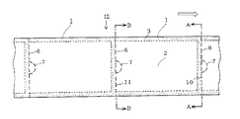
図1は、薬袋連続体の第一実施の形態概略斜視図である。
図1中の矢印は、薬袋連続体12のプリンタ搬送方向である。薬袋連続体12は、帯状連続紙からなる印字紙2と同一形状の裏紙5とを貼り合わせてなり、ミシン目6を介して切り取ったときに薬袋1の底部と隣の薬袋1の開口部を形成するように、略コ字状に各薬袋1の三辺を接着剤3によって貼り合せて袋状に区画して形成している。また、各薬袋1の開口部には、指掛け穴となる切取部7を印字紙2に設けている。さらに、各薬袋1の裏紙5には、プリンタによる印字方向に対して各薬袋1の底部が先頭となるように、印字開始位置を決定するアイマーク8が印刷されている。つまり、薬袋連続体12は、プリンタにて印字される薬袋1の連続体である。
図1では、薬袋連続体12の薬袋1は、2連続毎に折り返して積み重ねられているが、連続して連なっていれば良く、この折り返しの単位は任意に設定できる。また、巻き芯に巻回してロール状に形成しても良い。
【0015】
図2は、薬袋連続体の第一実施の形態平面図である。
また、図2中の矢印は、薬袋連続体12のプリンタ搬送方向である。薬袋連続体12において、ミシン目6によって区画された薬袋1が一袋単位で、薬袋発行プリンタの印字動作に伴い、搬送開始される部分がプリンタ搬送始端部10であり、搬送終了される部分がプリンタ搬送終端部11である。薬袋連続体12は、プリンタ搬送始端部10から、薬袋1の全幅に亘って薬袋発行プリンタの印字ヘッドに圧接されたまま、プリンタのプラテンにより、プリンタ搬送終端部11まで搬送され、薬袋1の印字紙2に後述する患者情報や薬剤情報の文字およびバーコードが印字される。
【0016】
印字紙2には、薬袋発行プリンタ印字ヘッドの熱により、熱転写リボンによる印字が行われる。したがって、リボン熱転写印字に適した塗工紙であるコート紙が用いられる。また、コート紙に限らず熱転写リボンが不要でプリンタ印字ヘッドの熱により発色する感熱紙を用いても良い。
この場合、感熱紙としては耐光性を有する耐光感熱紙を用いるのが好ましい。耐光感熱紙は通常の感熱紙と比較して、画像保存性に優れ、高耐熱性と高耐光性を有するため、元々の印字濃度が徐々に薄くなったり、高い気温や強い光が当たる環境下でも発色することが少ないからである。
要するに、薬剤は一般的に冷暗所保存されることから、薬袋の印字紙が感熱紙であっても耐光感熱紙であれば問題なく使用できる。
【0017】
接着剤3は、印字紙2と裏紙5とが剥がれることなく接着されれば良く、接着剤の種類は限定しない。
ただし、接着剤3の塗布厚は、薄いほど接着剤塗布面と接着剤非塗布面との段差が少なくなるため、プリンタ印字や搬送に適しており、接着剤3の塗布厚は5〜20μmが好ましい。塗布厚が5μm未満だと印字紙2と裏紙5の貼り合わせが不充分で剥がれが生じやすくなる。塗布厚が20μmを超えると接着剤塗布面と接着剤非塗布面との段差が大きくなり、薬袋発行プリンタでの印字時に、接着剤非塗布面に印字カスレが生じやすくなる。
また、接着剤3の塗布幅は、狭いほど接着剤塗布面と接着剤非塗布面との段差幅が少なくなるため、プリンタ印字や搬送に適しており、接着剤3の塗布幅は5mm程度が好ましい。塗布幅が5mm未満だと印字紙2と裏紙5の貼り合わせが不充分で剥がれが生じやすくなる。一方、接着剤塗布面は通常では余白部として印字しないことから、塗布幅が5mmを超えると印字領域が狭くなるという不都合がある。
【0018】
ミシン目6は、プリンタ印字発行後の薬袋連続体12を一袋単位の薬袋1に切離すとともに、この切離した位置に開口部を形成する。また、ミシン目6のカット部と非カット部とは、薬袋1の切離しが容易に行われるよう、カット部に対して非カット部が少ない比率であれば、その比率は任意に設定される。
切取部7は、これを切り取ることにより一袋単位に切離された薬袋1の開口部に指掛け穴を形成し、密着した印字紙2と裏紙5とを容易に開口するために設けられており、切り取りを容易にするため3カ所の非カット部を含む半円型のカット部を設けている。切取部7は、薬袋1の開口部に指掛け穴を形成するために、印字紙2にカット部が形成されれば良く、そのカット部の形状や非カット部については図示のものに限定されず任意に設定できる。また、切取部7はあらかじめ印字紙2から取り除かれた状態であっても良い。
【0019】
図3は、薬袋連続体の第一実施の形態裏面図である。
また、図3中の矢印は、薬袋連続体12のプリンタ搬送方向である。裏紙5は、後述する薬袋発行プリンタ印字時の印字開始位置を決定するアイマーク8が一定間隔で印刷されている。裏紙5はアイマーク8の印刷適正を有していれば良く、リボン熱転写印字に適したコート紙(塗工紙)である必要はない。非塗工紙である上質紙等でも良く、コスト的に安価な選択もできる。
なお、薬袋発行プリンタによる印字時の印字開始位置を決定するマークは、反射型センサに対応するアイマーク8には限定されず、透過型センサにより接着剤3による貼り合わせ部やミシン目6の部分を読み取るようにしても良い。
【0020】
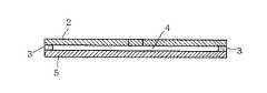
図4は図2中のA−A線断面図であり、一袋単位に区画された薬袋1の、プリンタ搬送始端部10の断面図である。
図2中のA−A線断面は上層より、印字紙2、接着剤3、裏紙5の順に積層されている。裏紙5にはアイマーク8が印刷されている。
【0021】
図5は、図2中のB−B線断面図であり、一袋単位に区画された薬袋1の、プリンタ搬送終端端部11の断面図である。
図2中のB−B線断面は上層より、印字紙2、接着剤3、裏紙5の順に積層されている。印字紙2には切取部7を形成する切取線のカットが形成されている。接着剤3は幅方向の両端部のみに塗工され、中央部には開口部4が形成されている。前述のとおり、接着剤3は、その塗布厚に比例して開口部4の距離も変動する。したがって、接着剤3の塗布厚が厚くなれば開口部4の距離が広がり開口は容易となる。しかし、前述のとおり薬袋発行プリンタでの印字時においては、接着剤3が塗布された両端部と比較して、開口部4が設けられた中央部は、印字ヘッドの圧接力が弱くなるため、印字カスレが生じやすくなる。
また、図2中の矢印方向へ、プリンタ搬送始端部10からプリンタ搬送終端部11方向に搬送が行われても、切取部7のカット部とミシン目6のカット部が、薬袋1の袋状部分に溜まった空気の逃げ途となる。
したがって、印字紙2のシワ発生が防止され、薬袋連続体12の詰まりも防止される。
【0022】
以下に、本発明に係る薬袋連続体の第二実施の形態について、図6から図9に基づき説明する。
なお、先に述べた第一実施の形態と同一の部分には同一符号を付し、詳説を省略する。
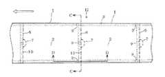
図6は、薬袋連続体の第二実施の形態平面図である。
また、図6中の矢印は、薬袋連続体12のプリンタ搬送方向である。
図6は、前述した図2の薬袋連続体の第一実施の形態平面図と比較して、非接着部9が設けられており、薬袋連続体12のプリンタ搬送方向が逆となっている。
【0023】
非接着部9は、各薬袋1のミシン目6(プリンタ搬終端部11)に接する貼り合わせ辺部の中央部分一ヶ所と、各薬袋1が搬送される方向の両側貼り合わせ辺部のプリンタ搬終端部11近傍にそれぞれ一ヶ所に設けられている。つまり、開口部以外の三方辺部の三ヶ所に設けられている。
非接着部9は、接着剤3を塗布しない部分を形成したり、印字紙2または裏紙5に剥離剤を塗布するなどして接着しない部分を形成すれば良く、その形成方法については特に限定しない。
なお、非接着部9の幅は特に限定しないが、図6の位置に三ヶ所設けた場合は1mm程度が好ましい。
また、非接着部9は図6の位置と数に関わらず、少なくともいずれか一辺のプリンタ搬送終端部11近傍に、部分的に薬袋1の内外を連通させるように、通気孔となる部分を形成すれば良い。
【0024】
図7は、薬袋連続体の第二実施の形態裏面図である。
また、図7中の矢印は、薬袋連続体12のプリンタ搬送方向である。
図7は、図3の薬袋連続体の第一実施の形態の裏面図と比較して、非接着部9が設けられており、薬袋連続体12のプリンタ搬送方向が逆となっている点のみが異なる。
【0025】
図8は、図6中のC−C線断面図であり、一袋単位に区画された薬袋1の、プリンタ搬送終端端部11の断面図である。
断面は上層より、印字紙2、接着剤3、裏紙5の順に構成される。接着剤3には幅方向の略中央部に非接着部9が形成され、裏紙5にはアイマーク8が印刷されている。
図6中の矢印方向へ、プリンタ搬送始端部10からプリンタ搬送終端部11方向に搬送が行われても、前記接着剤3の幅方向の略中央部に形成された非接着部9が、通気孔となって薬袋1の袋状部分に溜まった空気の逃げ途となる。
【0026】
図9は、図6中のD−D線断面図である。
また、図9中の矢印はプリンタ搬送方向である。断面は上層より、印字紙2、接着剤3、裏紙5の順に構成される。前記全ての層を貫通してミシン目6のカット部が形成され、接着剤3には、ミシン目6(プリンタ搬送終端部11)の近傍に、非接着部9が形成され、裏紙5にはアイマーク8が印刷されている。
図6中の矢印方向へ、プリンタ搬送始端部10からプリンタ搬送終端部11方向に搬送が行われても、前記接着剤3のミシン目6(プリンタ搬送終端部11)の近傍に形成された非接着部9が、通気孔となって薬袋1の袋状部分に溜まった空気の逃げ途となる。
【0027】
また、図6中の矢印とは逆方向へ搬送が行われても、切取部7とミシン目6のカット部が薬袋1の袋状部分に溜まった空気の逃げ途となることは、前述の第一実施の形態と同様である。
つまり、本発明に係る第二実施の形態では、薬袋連続体12において、各薬袋1の袋状部分に溜まった空気の逃げ途となる部分を、切取部7とミシン目6の一辺(開口部)と、非接着部9として他方の三辺にも設けた。
したがって、四辺すべてに、各薬袋1の袋状部分に溜まった空気の逃げ途を設けたことから、薬袋発行プリンタの搬送方向に関わらず、印字紙2のシワ発生が防止され、薬袋連続体12の詰まりも防止される。
【0028】
次に、本発明に係る薬袋の運用システムについて説明する。
【0029】
まず、薬袋の運用システムの処方箋発行について、図10乃至図14に基づき説明する。
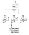
図10は、薬袋の運用システムの概略図である。
薬袋の運用システムは、ネットワーク60に接続された、ホストコンピュータ50と、第一の端末装置51と、複数の第二の端末装置61a、61bと、薬剤保管棚70などから構成される。
前記薬袋の運用システムの処方箋の発行は、病院内にて行われるもので、第一の端末装置51が用いられる。図10では第一の端末装置51は一台のみとなっているが、実際の運用にあたっては医師が患者を診察する場所ごとに設置され、コンピュータ52、ディスプレイ53、キーボード54から構成され、処方箋発行プリンタ55とスキャナ56aが接続されている。
また、ホストコンピュータ50には、患者情報として患者番号テーブルが登録されており、薬剤情報として薬剤の名称テーブルが登録されている。
【0030】
次に、ホストコンピュータ50に登録されている、前記患者番号テーブルについて説明する。
図11は、薬袋の運用システムの患者番号テーブルである。
患者番号テーブル18は、患者番号欄21と、患者名欄23と、性別欄24と、生年月日欄25と、血液型欄26と、健康保険証番号欄27などからなる。
図11の例として、患者番号欄21の「123456789」には、患者名欄23に「あいうえお」、性別欄24に「おとこ」、生年月日欄25に「S47.1.1」、血液型欄26に「A」、健康保険証番号欄27に「1357−2468」が登録されている。
【0031】
次に、ホストコンピュータ50に登録されている、前記薬剤の名称テーブルについて説明する。
図12は、薬袋の運用システムの薬剤の名称テーブルである。
薬剤の名称テーブル19は、薬剤の名称欄30と、薬剤の用量欄36と、薬剤の用途欄35と、薬剤の形状欄37などからなる。
図12の例として、薬剤の名称欄30の「ABCD錠10mg」には、薬剤の用量欄36に「10mg」、薬剤の用途欄35に「せきを止めるくすり」、薬剤の形状欄37に「錠剤」が登録されている。
【0032】
次に、患者の外来受付について説明する。
前記薬袋の運用システムの処方箋発行では、病院の外来受付にも、図10の第一の端末装置51と同一の端末装置が設置されている。この病院の外来受付に設置された第一の端末装置51から、前記患者番号テーブル18の各項目が入力され、ホストコンピュータ50に保存される。
詳しくは、患者の来院初回時に、外来受付に設置された前記第一の端末装置51から、患者番号欄21の患者番号が新規に付番され、健康保険証や患者の記入事項に基づいて、患者番号テーブル18の各項目欄が入力され、ネットワーク60を介してホストコンピュータ50に登録される。
次に、前記第一の端末装置51に接続された処方箋発行プリンタ55には、処方箋の用紙ではなくラベルが装着されており、前記の新規に付番された患者番号をコード化したバーコードラベルが発行される。
次に、患者番号テーブル18の各項目が記入されたカルテが新規に作成される。図示せぬこのカルテは、従来より使用されている診察内容を記入する形式のもので、前記の新規に付番された患者番号をコード化したバーコードラベルが、カルテの所定の位置に貼付される。
以上のように、患者番号をコード化したバーコードラベルが貼付された図示せぬカルテは、外来受付から担当医の診察場所へ送られ、患者は医師の診察待ちとなる。
再来患者に関しては、外来受付にて保管管理されている、図示せぬカルテが選出され、担当医の診察場所へ送られ、医師の診察待ちとなる。
【0033】
次に、医師による処方箋発行について説明する。
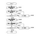
図13は、薬袋の運用システムの処方箋発行フローチャート図である。
医師は、患者の病状を判断して、診断した内容を図示せぬカルテに記入し、処方箋を作成する。
まず、医師による処方箋作成にあたり、第一の端末51に接続されたスキャナ56aにより、図示せぬ、カルテのバーコードラベルの患者番号読み取り(ステップS101)が行われる。これにより、第一の端末装置51からホストコンピュータ50へ読み取ったデータが送信される。
次に、ホストコンピュータより患者情報取り込み(ステップS102)が行われる。前記(ステップS101)にて第一の端末装置51からホストコンピュータ50へ送信されたデータに基づき、ホストコンピュータ50の患者番号テーブル18の対応した患者名欄23、性別欄24、生年月日欄25、血液型欄26、健康保険証番号欄27などの患者情報が、ホストコンピュータ50から第一の端末装置51に送信され、第一の端末装置51に接続されたディスプレイ53に表示される。
【0034】
次に、第一の端末装置51から、薬剤選択(ステップS103)が行われる。これにより、医師が患者に処方する薬剤の名称が選択される。詳しくは、第一の端末装置51から薬剤情報の呼び出しを選択すると、ホストコンピュータ50から薬剤名称テーブル19が呼び出され、第一の端末装置51へ送信される。これにより、第一の端末装置51に接続されたディスプレイ53に薬剤の名称テーブル19が表示され、処方する薬剤の名称を選択する。これにより、第一の端末装置51からホストコンピュータ50へ、処方する薬剤の名称を選択した情報が送信される。
次に、ホストコンピュータより薬剤情報取り込み(ステップS104)が行われる。前記(ステップS103)にて第一の端末装置51からホストコンピュータ50へ送信された、薬剤の名称のデータに基づき、ホストコンピュータ50の薬剤名称テーブル19の、薬剤の名称に対応した、薬剤の用量欄36、薬剤の用途欄35、薬剤の形状欄37などの薬剤情報がホストコンピュータ50から第一の端末装置51に送信され、第一の端末装置51に接続されたディスプレイ53に表示される。
【0035】
次に、第一の端末装置51から、服用方法入力(ステップS105)が行われる。詳しくは、前記(ステップS103)にて薬剤選択した薬剤について、第一の端末装置51に接続されたキーボード54から薬剤の服用時期、服用個数、服用日数などの服用方法を入力する。
【0036】
次に、第一の端末装置51から薬剤の処方が終了か?(ステップS106)を選択する。
引き続き処方する薬剤があり、薬剤の処方が終了でなければ薬剤選択(ステップS103)に戻る。
また、処方する薬剤がなく、薬剤の処方が終了であれば処方箋発行(ステップS107)へ進む。
処方箋発行(ステップS107)では、第一の端末装置51に接続されたディスプレイ53にて、発行される処方箋の内容を確認することができる。処方箋の内容に修正があればステップS103またはステップS105へ戻り修正することができる。
また、修正がなく処方箋発行を選択すると、第一の端末装置51に接続された処方箋発行プリンタ55より、処方箋が発行される。これにより、処方箋内容を示す患者情報と薬剤情報と服用方法とが、コード化されたバーコードと文字が印字された、処方箋が発行される。
【0037】
次に、ホストコンピュータ50へ送信(ステップS108)が行われる。これにより医師が処方した処方箋データが、第一の端末装置51からホストコンピュータ50へ送信される。ホストコンピュータ50は、受信した処方箋データを保存する。
【0038】
なお、上記の処方箋発行フローチャートにおいて、服用方法選択(ステップS105)にて、薬剤の服用時期、服用個数、服用日数が入力されるため、処方箋発行(ステップS107)時には自動的に処方される薬剤の総数と、総数をコード化したバーコードが印字される。
たとえば、薬剤の服用時期として1日3回朝昼夕食後が入力され、服用個数として1回1錠が入力され、服用日数として14日が入力されると、自動的に処方される薬剤の総数として42が計算され、この薬剤の総数である42と、薬剤の総数である42をコード化した薬剤の総数バーコードが印字される。
【0039】
次に、薬袋の運用システムの処方箋について説明する。
図14は、薬袋の運用システムの処方箋説明図である。
前述の処方箋発行フローチャートに基づき発行された、処方箋20には、患者情報として患者番号欄21と、患者番号バーコード22と、患者名欄23と、性別欄24と、生年月日欄25と、血液型欄26と、健康保険証番号欄27などが印字される。
図14の例として、患者番号欄21に「123456789」、患者番号バーコード22に「123456789」をコード化したバーコード、患者名欄23に「あいうえお」、性別欄24に「おとこ」、生年月日欄25に「S47.1.1」、血液型欄26に「A」、健康保険証番号欄27に「1234−5678」が印字される。
さらに、薬剤情報として薬剤の名称欄30と、薬剤の名称バーコード31と、服用方法と服用総数32と、服用方法バーコード33などが印字される。
図14の例として、処方される薬剤1の、薬剤の名称欄30に「ABCD錠10mg」、薬剤の名称バーコード31に「ABCD錠10mg」をコード化したバーコード、服用方法と服用総数32に「1日3回朝昼夕食後1回1錠14日分42」、服用方法バーコード33に「1日3回朝昼夕食後1回1錠14日分42」をコード化したバーコードが印字される。前記42は薬剤の総数であり、錠やカプセルや袋などの形状の単位は省略されている。
【0040】
なお、薬袋の運用システムのバーコードは、一般的によく使われているバーコード、JAN、CODE39、NW−7、ITFの中でCODE39が使用される。
CODE39は、0から9までの数字と、AからZまでのアルファベットと、特定の記号が使用可能である。したがって、英字の表現が可能である。また、JAN、CODE39、NW−7、ITFの中でバーコードの誤読率が最も低く、バーコード読み取りの正確さが要求される場合に適しているからである。
たとえば、前記処方箋薬剤1のABCD錠10mgを、薬剤名称(ABCD)、形状(錠)、用量(10mg)で区切り、区切りの部分をスペースとして表すと、ABCDスペースT(錠剤を意味するTABLETの頭文字)スペース10MGで表すことができ、CODE39による表現が可能である。
【0041】
次に、薬袋の運用システムの薬袋発行と薬剤照合について、図10、図15乃至図17に基づき説明する。
まず、薬袋運用システムの薬袋発行と薬剤照合の構成について説明する。
前記薬袋の運用システムの薬袋発行と薬剤照合は、薬局内にて行われるもので、図10のネットワーク60に接続されたホストコンピュータ50と、ネットワーク60に接続された薬局内の少なくとも二台の第二の端末装置61a、61bと、薬剤保管棚70とが用いられる。
前記第二の端末装置61aは、コンピュータ62、ディスプレイ63、キーボード64から構成され、スキャナ56a、56bと薬袋発行プリンタ65が接続される。また、前記第二の端末装置61bは、コンピュータ62、ディスプレイ63、キーボード64から構成され、スキャナ56aと会計伝票発行プリンタ66が接続される。
前記第二の端末装置61aに接続されたスキャナ56bは、読み取ったバーコードの内容を表示する表示部と、数値を入力できる入力部と、バーコードとバーコードまたはバーコードと入力数値を照合する照合部と、前記照合部の照合結果を報知する報知部とを有している。
前記薬剤保管棚70は、おのおの区切られた棚に薬剤71が保管されている。また、おのおの区切られた棚には、保管されている薬剤71の、薬剤の名称欄30と薬剤の名称バーコード31が表示されている。なお、薬剤保管棚70は棚に限らず、薬剤の名称欄30と薬剤の名称バーコード31が表示された箱などであっても良い。
【0042】
次に、薬袋の運用システムの薬袋発行について説明する。
図15は、薬袋運用システムの薬袋発行フローチャート図である。
まず、病院で前記処方箋20を受け取った患者は、薬局に前記処方箋20を提出する。
前記処方箋20を受け取った薬局では、局員が薬袋を発行するにあたり、処方箋の患者番号バーコード読み取り(ステップS201)が行われる。
詳しくは、患者が薬局に提出した処方箋20の患者番号バーコード22が、第二の端末装置61aに接続されたスキャナ56aにより読み取られる。これにより、第二の端末装置61aからホストコンピュータ50へ読み取ったデータが送信される。
次に、ホストコンピュータ50より患者情報取り込み(ステップS202)が行われる。これにより、ホストコンピュータ50の患者番号テーブル18の対応した患者名欄23が、ホストコンピュータ50から第二の端末装置61aへ送信され、第二の端末装置61aに取り込まれる。
【0043】
次に、処方箋の薬剤の名称バーコード読み取り(ステップS203)が行われる。
詳しくは、処方箋20の薬剤の名称バーコード31が、第二の端末装置61aに接続されたスキャナ56aにより読み取られる。これにより、第二の端末装置61aからホストコンピュータ50へ、読み取った薬剤の名称バーコード31のデータが送信される。
次に、ホストコンピュータ50より薬剤情報取り込み(ステップS204)が行われる。これにより、ホストコンピュータ50の薬剤の名称テーブル19の、対応した薬剤情報が、ホストコンピュータ50から第二の端末装置61aへ送信され、薬剤の名称欄30、薬剤の用途欄35、薬剤の用量欄36、薬剤の形状欄37が、第二の端末装置61aに取り込まれる。
【0044】
次に、処方箋の服用方法バーコード読み取り(ステップS205)が行われる。
詳しくは、処方箋20の服用方法バーコード33が、第二の端末装置61aに接続されたスキャナ56aにより読み取られる。これにより、服用方法と薬剤総数が、第二の端末装置61aに取り込まれる。
【0045】
次に、第二の端末装置61aから薬剤の処方が終了か?(ステップS206)を選択する。
引き続き処方される薬剤があり、薬剤の処方が終了でなければ、処方箋の薬剤の名称バーコード読み取り(ステップS203)に戻る。
また、処方する薬剤がなく、薬剤の処方が終了であれば、薬袋発行(ステップS207)が行われる。
以上のとおり、前記第二の端末装置61aに取り込まれた情報に基づいて、第二の端末装置61aに接続された薬袋発行プリンタ65から、処方された薬剤の種類ごとに薬袋1が発行される。
【0046】
次に、薬袋の運用システムの薬袋について説明する。
図16は、薬袋の運用システムの薬袋説明図である。
前述のとおり薬袋発行プリンタ65から発行される薬袋1には、前記処方箋20の患者番号バーコード22から、患者情報として患者名欄23が「あいうえお」と印字される。
また、前記処方箋20の服用方法バーコード33から、薬剤情報として1日の服用回数と服用時期と服用個数と服用日数と薬剤総数を示す服用方法34が「1日3回1回1錠朝昼夕食後14日分42」と、服用時期欄には服用時期38が「朝、昼、夕」と、服用個数欄には服用個数39が「1、1、1」と印字される。また、前記処方箋20の薬剤の名称バーコード31から、用途欄には薬剤の用途欄35が「せきを止めるくすり」、名称欄には薬剤の名称欄30が「ABCD錠」、用量欄には薬剤の用量欄36が「10mg」、形状欄には薬剤の形状欄37が「錠剤」と印字される。
また、名称欄には薬剤の名称バーコード31として「ABCD錠」をコード化したバーコードが、総数欄には薬剤の総数バーコード40として「42」をコード化したバーコードが、番号欄には患者番号バーコード22として「123456789」をコード化したバーコードが印字される。
また、薬局名と所在地と電話番号を示す薬局名41と、調剤した年月日を示す調剤年月日42と、薬剤師押印欄43とが印字される。なお、薬局名41と薬剤師押印欄43とは薬袋1にあらかじめ印刷されていても良い。
【0047】
次に、薬袋の運用システムの薬剤照合について説明する。
図17は、薬袋運用システムの薬剤照合フローチャート図である。
前記薬袋1が発行された薬局では、局員が薬剤を選出するにあたり、薬袋の薬剤名称読み取り(ステップS301)が行われる。詳しくは、薬袋1の薬剤の名称バーコード31が、第二の端末装置61aに接続されたスキャナ56bにより読み取られ、スキャナ56bの表示部に表示される。
次に、薬剤保管棚70から、選出する薬剤名称読み取り(ステップS302)が行われる。詳しくは、薬剤保管棚70から選出する薬剤71に対応した薬剤の名称バーコード31が、第二の端末装置61aに接続されたスキャナ56bにより読み取られ、スキャナ56bの表示部に表示される。
そして、薬袋1の薬剤の名称バーコード31と、薬剤保管棚70から選出する薬剤の名称バーコード31とが、一致するか(ステップS303)の判断が、スキャナ56bの照合部において判断される。
一致しなければ、スキャナ56bの報知部よりエラー報知(ステップS304)が行われ、選出する薬剤名称読み取り(ステップS302)へ戻る。
また、一致するか(ステップS303)で一致すれば、スキャナ56bの表示部に表示され、薬剤名称の照合は終了し、薬剤総数の照合へ進む。
【0048】
薬剤総数の照合では、薬袋の薬剤総数読み取り(ステップS305)が行われる。詳しくは、薬袋1の薬剤総数バーコード40が、スキャナ56bにより読み取られ、スキャナ56bの表示部に表示される。
次に、選出した薬剤総数を入力(ステップS306)される。詳しくは、薬剤保管棚70から選出した薬剤71の総数が、スキャナ56bの入力部から入力され、スキャナ56bの表示部に表示される。
そして、薬袋1の薬剤総数バーコード40が示す数値と、前記スキャナ56bの入力部から入力された数値(選出した薬剤71の総数)とが、一致するか(ステップS307)の判断が、スキャナ56bの照合部において判断される。
一致しなければ、スキャナ56bの報知部よりエラー報知(ステップS308)が行われ、選出する薬剤総数を入力(ステップS306)へ戻る。
また、一致するか(ステップS307)で一致すれば、スキャナ56bの表示部に表示され、薬剤照合は終了となる。
【0049】
以上のとおり薬剤照合が行われ、照合された薬剤71が入れられた薬袋1は、処方箋20とともに会計処理される。
つまり、第二の端末装置61bに接続されたスキャナ56aにより、会計処理に必要な患者情報として前記薬袋1の患者番号バーコード22と、薬剤の単価情報呼び出しのため前記薬袋1の薬剤の名称バーコード31と、選出した薬剤の総数読み取りのため前記薬袋1の薬剤総数バーコード40とが読み取られる。これらの情報に基づいて、会計処理がなされ、第二の端末装置61bに接続された会計伝票発行プリンタ66から、会計伝票が発行される。
次に、患者へ薬剤71が入れられた薬袋1が引き渡され、前記会計伝票に従い、会計が行われる。
なお、上記会計処理の詳細については省略する。
以上で、薬袋運用システムの薬袋発行と薬剤照合は終了となる。
【0050】
上述の、薬袋の運用システムにおけるバーコードは二次元コードであっても良く、その場合薬袋の運用システムのバーコード部分は二次元コードに置き換えることができる。
【0051】
なお、本発明が上記実施の形態に限定されず、本発明の技術思想の範囲内において、各実施の形態は適宜に変更され得ることは明らかである。また、上記構成部材の数、位置、形状等は上記実施の形態に限定されず、本発明を実施する上で好適な数、位置、形状にすることができる。
【0052】
【発明の効果】
以上のように、請求項1の発明によれば、薬袋がミシン目を介して連続形成された薬袋連続体であって、プリンタによる印字方向に対して各袋の底部が先頭となるように搬送され、開口部に指掛け穴となる切取部を設けた薬袋連続体としたので、薬袋を補充する手間がかからず、薬袋の詰まりやシワが発生しない薬袋連続体が得られる。
また、請求項2の発明によれば、薬袋がミシン目を介して連続形成された薬袋連続体であって、部分的に薬袋の内外を連通させるように非接着部からなる通気孔を設け、開口部に指掛け穴となる切取部を設けた薬袋連続体としたので、薬袋を補充する手間がかからず、プリンタ搬送方向に関わらず薬袋の詰まりやシワが発生しない薬袋連続体が得られる。
また、請求項3の発明によれば、ホストコンピュータにネットワークで接続された複数の端末装置と、第一の端末装置に接続された処方箋発行プリンタと、第二の端末装置に接続された薬袋発行プリンタとスキャナと、を有し、薬剤保管棚に薬剤情報としてのバーコードを表示するようにしたので、患者情報と薬剤情報と服用方法およびこれらをコード化したバーコードなどが印字された、処方箋と薬袋とが得られる。さらに、薬袋のバーコードと薬剤保管棚から選出される薬剤のバーコードとを照合して確認することができる。
また、請求項4の発明によれば、患者情報と薬剤情報と服用方法およびこれらをコード化したバーコードなどを印字する処方箋としたので、正確な情報が印字された処方箋が得られる。
また、請求項5の発明によれば、患者情報と薬剤情報と服用方法およびこれらをコード化したバーコードなどを印字する薬袋としたので、正確な情報が印字された薬袋が得られる。
【図面の簡単な説明】
【図1】薬袋連続体の第一実施の形態概略斜視図
【図2】薬袋連続体の第一実施の形態平面図
【図3】薬袋連続体の第一実施の形態裏面図
【図4】図2中のA−A線断面図
【図5】図2中のB−B線断面図
【図6】薬袋連続体の第二実施の形態平面図
【図7】薬袋連続体の第二実施の形態裏面図
【図8】図6中のC−C線断面図
【図9】図6中のD−D線断面図
【図10】薬袋の運用システムの概略図
【図11】薬袋の運用システムの患者番号テーブル
【図12】薬袋の運用システムの薬剤の名称テーブル
【図13】薬袋の運用システムの処方箋発行フローチャート図
【図14】薬袋の運用システムの処方箋説明図
【図15】薬袋の運用システムの薬袋発行フローチャート図
【図16】薬袋の運用システムの薬袋説明図
【図17】薬袋の運用システムの薬剤照合フローチャート図
【符号の説明】
1 薬袋
2 印字紙
3 接着剤
4 開口部
5 裏紙
6 ミシン目
7 切取部
8 アイマーク
9 非接着部
10 プリンタ搬送始端部
11 プリンタ搬送終端部
12 薬袋連続体
18 患者番号テーブル
19 薬剤の名称テーブル
20 処方箋
21 患者番号欄
22 患者番号バーコード
23 患者名欄
24 性別欄
25 生年月日欄
26 血液型欄
27 健康保険証番号欄
30 薬剤の名称欄
31 薬剤の名称バーコード
32 服用方法と薬剤総数
33 服用方法バーコード
34 服用方法
35 薬剤の用途欄
36 薬剤の用量欄
37 薬剤の形状欄
38 服用時期
39 服用個数
40 薬剤総数バーコード
41 薬局名
42 調剤年月日
43 薬剤師押印欄
50 ホストコンピュータ
51 第一の端末装置
52、62 コンピュータ
53、63 ディスプレイ
54、64 キーボード
55 処方箋発行プリンタ
56a、56b スキャナ
60 ネットワーク
61a、61b 第二の端末装置
65 薬袋発行プリンタ
66 会計伝票発行プリンタ
70 薬剤保管棚
71 薬剤[0001]
TECHNICAL FIELD OF THE INVENTION
The present invention relates to a medicine bag continuum capable of printing a bar code and a medicine bag operation system.
[0002]
[Prior art]
As a conventional medicine bag printed by printer printing, an upper paper having a shape overlapping each other and a lower paper are provided, and a storage space having an opening at one side edge is formed between the upper paper and the lower paper, and the lower paper is formed. (See, for example, Patent Document 1).
However, in the above-mentioned medicine bags, since the medicine bags are formed one by one, the number of sheets that can be set in the printer at one time is limited, and the need to refill the medicine bags frequently occurs, which is troublesome. there were.
[0003]
As a conventional medicine bag making system, a storage device that stores information such as computerized medicine, and an input for selecting a necessary one based on a prescription from information such as medicines stored in the storage device An apparatus, a sorting program for sorting information such as the selected medicines for each medicine bag based on a sorting factor, and a medicine bag printing machine for displaying information such as sorted medicines on each medicine bag. A system is presented (for example, see Patent Document 2).
However, in the above-mentioned medicine bag making system, there is a problem that it is necessary to input the medicine information described in the prescription by the input device, which is troublesome.
[0004]
[Patent Document 1]
JP-A-11-130087 (pages 3-4, FIG. 1-2)
[Patent Document 2]
JP 2000-25719 A (pages 2-4, FIG. 2)
[0005]
[Problems to be solved by the invention]
The present invention has been made in view of the above-described problems of the related art, and an object of the present invention is to reduce the time and effort required to refill a medicine bag when printing and issuing with a printer. It is an object to provide a medicine bag continuum in which clogging does not occur.
[0006]
Another object of the present invention is to provide a medicine bag continuum that does not cause wrinkles in the medicine bag when printing is issued by a printer.
[0007]
Another object of the present invention is to provide a medicine bag operation system for issuing a prescription and a medicine bag on which a bar code is printed so that accurate information can be read by reading a bar code with a scanner. .
Another object of the present invention is to provide a medicine bag operation system capable of collating and confirming a barcode printed on a medicine bag with a medicine barcode.
[0008]
[Means for Solving the Problems]
The present invention has the following configurations in order to solve the above problems.
The invention according to
[0009]
The invention according to
[0010]
According to a third aspect of the present invention, a plurality of terminal devices connected to a host computer storing patient information and medicine information via a network, a prescription information connected to a first terminal device, and a bar coded therewith. A prescription issuance printer for issuing a prescription for printing codes and the like, a scanner connected to the second terminal device and reading a barcode printed on the prescription, patient information and medicine information from information read by this scanner, and A medicine bag issuance printer that issues a medicine bag that prints a coded barcode, etc., and has a barcode as medicine information displayed on a medicine storage shelf or medicine box, and a barcode printed on the medicine bag. And a scanner configured to read and collate the medicine bag.
[0011]
The invention according to
[0012]
In the invention according to
[0013]
BEST MODE FOR CARRYING OUT THE INVENTION
Hereinafter, embodiments of the present invention will be described in detail with reference to the drawings.
[0014]
First, a first embodiment of a continuous medicine bag according to the present invention will be described with reference to FIGS.
FIG. 1 is a schematic perspective view of a continuous medicine bag according to a first embodiment.
The arrow in FIG. 1 is the printer transport direction of the continuous
In FIG. 1, the
[0015]
FIG. 2 is a plan view of the first embodiment of the continuous medicine bag.
The arrow in FIG. 2 indicates the direction in which the
[0016]
Printing on the
In this case, it is preferable to use light-resistant heat-sensitive paper having light resistance as the thermal paper. Compared to ordinary thermal paper, light-fast thermal paper has better image storability, high heat resistance and high light resistance, so it can be used in environments where the original print density gradually decreases, or when it is exposed to high temperatures or strong light. However, it is less likely to develop color.
In short, since the medicine is generally stored in a cool and dark place, even if the printing paper of the medicine bag is heat-sensitive paper, it can be used without any problem as long as it is light-resistant heat-sensitive paper.
[0017]
The adhesive 3 only needs to be adhered without peeling the
However, the smaller the thickness of the adhesive 3 applied, the smaller the step between the adhesive-coated surface and the non-adhesive-coated surface. Therefore, the adhesive 3 is suitable for printer printing and conveyance, and the coating thickness of the adhesive 3 is 5 to 20 μm. preferable. When the coating thickness is less than 5 μm, the
Also, the narrower the application width of the adhesive 3 is, the smaller the step width between the adhesive-applied surface and the non-adhesive-applied surface is. Therefore, the adhesive 3 is suitable for printer printing and conveyance, and the application width of the adhesive 3 is about 5 mm. preferable. If the coating width is less than 5 mm, the
[0018]
The
The cut-out
[0019]
FIG. 3 is a rear view of the continuous medicine bag according to the first embodiment.
Arrows in FIG. 3 indicate the direction in which the
The mark for determining the printing start position at the time of printing by the medicine bag issuing printer is not limited to the
[0020]
FIG. 4 is a cross-sectional view taken along line AA in FIG. 2, and is a cross-sectional view of the printer transport start
2, the
[0021]
FIG. 5 is a cross-sectional view taken along the line BB in FIG. 2, and is a cross-sectional view of the printer transport terminal end 11 of the
2, a
Further, even if the transfer is performed from the printer transfer start
Therefore, the generation of wrinkles on the
[0022]
Hereinafter, a second embodiment of the continuous medicine bag according to the present invention will be described with reference to FIGS. 6 to 9.
The same parts as those in the first embodiment described above are denoted by the same reference numerals, and detailed description will be omitted.
FIG. 6 is a plan view of a second embodiment of the continuous medicine bag.
The arrow in FIG. 6 indicates the direction in which the
FIG. 6 is different from the plan view of the first embodiment of the continuous medicine bag shown in FIG. 2 in that the
[0023]
The
The
The width of the
In addition, regardless of the position and the number of the
[0024]
FIG. 7 is a rear view of the continuous medicine bag according to the second embodiment.
The arrow in FIG. 7 indicates the direction in which the
FIG. 7 is different from the rear view of the first embodiment of the continuous medicine bag of FIG. 3 only in that the
[0025]
FIG. 8 is a cross-sectional view taken along the line CC in FIG. 6, and is a cross-sectional view of the printer transport terminal end 11 of the
The cross section is composed of printing
Even if the conveyance is performed from the printer conveyance start
[0026]
FIG. 9 is a sectional view taken along line DD in FIG.
The arrow in FIG. 9 indicates the printer transport direction. The cross section is composed of printing
Even if the conveyance is performed from the printer conveyance start
[0027]
Also, even if the conveyance is performed in the direction opposite to the arrow in FIG. 6, the
That is, in the second embodiment according to the present invention, in the
Therefore, since all four sides are provided with a way to escape the air accumulated in the bag-shaped portion of each
[0028]
Next, a medicine bag operation system according to the present invention will be described.
[0029]
First, issuance of a prescription in the medicine bag operation system will be described with reference to FIGS.
FIG. 10 is a schematic diagram of a medicine bag operation system.
The medicine bag operation system includes a host computer 50, a first
The prescription issuance of the medicine bag operation system is performed in a hospital, and the first
In the host computer 50, a patient number table is registered as patient information, and a drug name table is registered as drug information.
[0030]
Next, the patient number table registered in the host computer 50 will be described.
FIG. 11 is a patient number table of the medicine bag operation system.
The patient number table 18 includes a
As an example of FIG. 11, "123456789" in the
[0031]
Next, the medicine name table registered in the host computer 50 will be described.
FIG. 12 is a medicine name table of the medicine bag operation system.
The drug name table 19 includes a
As an example of FIG. 12, “10 mg” is entered in the
[0032]
Next, outpatient reception of a patient will be described.
In the prescription issuance of the medicine bag operation system, the same terminal device as the first
Specifically, at the first visit to the patient, a patient number in the
Next, on the prescription issuing printer 55 connected to the first
Next, a chart in which each item of the patient number table 18 is entered is newly created. This chart, which is not shown, is a format for filling in the contents of a diagnosis that has been conventionally used, and a bar code label encoding the newly numbered patient number is attached to a predetermined position on the chart. You.
As described above, the medical chart (not shown) to which the bar code label encoding the patient number is attached is sent from the outpatient reception to the consultation place of the attending physician, and the patient is waiting for the doctor's consultation.
With respect to the returning patient, a chart (not shown) stored and managed at the outpatient reception desk is selected, sent to the consulting place of the attending physician, and awaiting a doctor's consultation.
[0033]
Next, the issue of a prescription by a doctor will be described.
FIG. 13 is a flowchart of the prescription issuance of the medicine bag operation system.
The doctor determines the condition of the patient, writes the contents of the diagnosis in a chart (not shown), and prepares a prescription.
First, when a doctor prepares a prescription, the
Next, patient information is taken in by the host computer (step S102). Based on the data transmitted from the first
[0034]
Next, medicine selection (step S103) is performed from the first
Next, drug information is taken in by the host computer (step S104). Based on the drug name data transmitted from the first
[0035]
Next, a dosing method input (step S105) is performed from the first
[0036]
Next, is the prescription of the medicine completed from the first
If there is a drug to be subsequently prescribed and the prescription of the drug is not completed, the process returns to the drug selection (step S103).
If there is no medicine to prescribe and the prescription of the medicine is completed, the process proceeds to prescription issuance (step S107).
In the prescription issuance (step S107), the contents of the issued prescription can be confirmed on the
When prescription issuance is selected without correction, a prescription is issued from the prescription issuance printer 55 connected to the first
[0037]
Next, transmission to the host computer 50 is performed (step S108). Thus, the prescription data prescribed by the doctor is transmitted from the first
[0038]
In the above-mentioned prescription issuance flowchart, the time of taking the medicine, the number of the medicines taken, and the number of days of the medicine are inputted in the method of taking the medicine (step S105). The total number and a barcode that encodes the total number are printed.
For example, if the time of taking a drug is three times a day after lunch, lunch and dinner, one tablet is once entered as the number of doses, and 14 days are entered as the number of days to be taken, the total number of drugs automatically prescribed Is calculated, and 42, which is the total number of medicines, and a barcode of the total number of medicines, which encodes 42, which is the total number of medicines, are printed.
[0039]
Next, a prescription of the medicine bag operation system will be described.
FIG. 14 is an explanatory diagram of a prescription of the medicine bag operation system.
The
As an example of FIG. 14, “123456789” is coded in the
Further, a
As an example of FIG. 14, a bar code obtained by coding “
[0040]
The barcode of the medicine bag operation system is CODE39 among commonly used barcodes, JAN, CODE39, NW-7, and ITF.
The
For example, when the
[0041]
Next, medicine bag issuing and medicine collation in the medicine bag operation system will be described with reference to FIGS. 10 and 15 to 17.
First, the configuration of medicine bag issuance and medicine collation in the medicine bag operation system will be described.
The medicine bag issuance and medicine collation of the medicine bag operation system are performed in the pharmacy, and the host computer 50 connected to the
The second terminal device 61a includes a
The scanner 56b connected to the second terminal device 61a collates the display unit for displaying the content of the read barcode, the input unit for inputting the numerical value, and the barcode with the barcode or the barcode and the input numerical value. A collating unit; and a notifying unit that reports a collation result of the collating unit.
The medicine storage shelves 70
[0042]
Next, issuance of a medicine bag in the medicine bag operation system will be described.
FIG. 15 is a medicine bag issuing flowchart of the medicine bag operation system.
First, a patient who has received the
At the pharmacy that has received the
Specifically, the
Next, patient information is taken in by the host computer 50 (step S202). Thereby, the corresponding
[0043]
Next, the name barcode of the medicine of the prescription is read (step S203).
Specifically, the
Next, the medicine information is taken in by the host computer 50 (step S204). Thereby, the corresponding medicine information of the medicine name table 19 of the host computer 50 is transmitted from the host computer 50 to the second terminal device 61a, and the
[0044]
Next, a prescription taking method barcode is read (step S205).
Specifically, the taking
[0045]
Next, is the prescription of the medicine completed from the second terminal device 61a? (Step S206) is selected.
If there is a drug to be subsequently prescribed and the prescription of the drug is not completed, the process returns to the reading of the prescription drug name bar code (step S203).
If there is no medicine to prescribe and the prescription of the medicine is completed, a medicine bag is issued (step S207).
As described above, the
[0046]
Next, the medicine bag of the medicine bag operation system will be described.
FIG. 16 is an explanatory diagram of a medicine bag of the medicine bag operation system.
As described above, in the
Also, from the
In the name column, a bar code obtained by coding "ABCD lock" as the drug
Also, a
[0047]
Next, drug collation in the medicine bag operation system will be described.
FIG. 17 is a medicine collation flowchart of the medicine bag operation system.
At the pharmacy to which the
Next, the name of the medicine to be selected is read from the medicine storage shelf 70 (step S302). Specifically, the
Then, the collation unit of the scanner 56b determines whether the
If they do not match, an error is notified by the notification unit of the scanner 56b (step S304), and the process returns to the reading of the selected drug name (step S302).
If they match (step S303), they are displayed on the display unit of the scanner 56b, the drug name matching ends, and the process proceeds to the drug total number matching.
[0048]
In the collation of the total number of medicines, the total number of medicines in the medicine bag is read (step S305). Specifically, the medicine
Next, the total number of selected medicines is input (step S306). Specifically, the total number of
Then, the scanner 56b determines whether the numeric value indicated by the drug total
If they do not match, an error is notified from the notification unit of the scanner 56b (step S308), and the total number of drugs to be selected is input (step S306).
If they match (step S307), they are displayed on the display unit of the scanner 56b, and the drug collation ends.
[0049]
The medicine collation is performed as described above, and the
That is, the
Next, the
The details of the accounting process will be omitted.
Thus, the issuance of the medicine bag and the medicine collation of the medicine bag operation system are completed.
[0050]
The barcode in the medicine bag operation system described above may be a two-dimensional code. In this case, the barcode portion of the medicine bag operation system can be replaced with a two-dimensional code.
[0051]
It is to be noted that the present invention is not limited to the above-described embodiment, and it is obvious that each embodiment can be appropriately changed within the scope of the technical idea of the present invention. Further, the number, position, shape, and the like of the constituent members are not limited to the above-described embodiment, and can be set to a number, position, and shape suitable for carrying out the present invention.
[0052]
【The invention's effect】
As described above, according to the first aspect of the present invention, the medicine bag is a continuous medicine bag formed continuously through the perforations, and is conveyed such that the bottom of each bag is first in the printing direction by the printer. Since the medicine bag continuum is provided with a cutout portion serving as a finger hole in the opening, it is not necessary to refill the medicine bag, and a medicine bag continuum without clogging or wrinkling of the medicine bag can be obtained.
According to the invention of
Further, according to the invention of
According to the fourth aspect of the present invention, since the prescription for printing the patient information, the medicine information, the dosing method, and the barcode or the like obtained by coding them is obtained, a prescription on which accurate information is printed can be obtained.
According to the fifth aspect of the present invention, since the medicine bag is used for printing the patient information, the medicine information, the method of taking the medicine, and the barcode or the like that encodes the information, a medicine bag on which accurate information is printed can be obtained.
[Brief description of the drawings]
FIG. 1 is a schematic perspective view of a first embodiment of a continuous medicine bag.
FIG. 2 is a plan view of a first embodiment of a continuous medicine bag.
FIG. 3 is a back view of the first embodiment of the continuous medicine bag.
FIG. 4 is a sectional view taken along line AA in FIG. 2;
FIG. 5 is a sectional view taken along line BB in FIG. 2;
FIG. 6 is a plan view of a second embodiment of a continuous medicine bag.
FIG. 7 is a rear view of a second embodiment of the continuous medicine bag.
8 is a sectional view taken along line CC in FIG. 6;
9 is a sectional view taken along line DD in FIG.
FIG. 10 is a schematic diagram of a medicine bag operation system.
FIG. 11 is a patient number table of the medicine bag operation system.
FIG. 12 is a medicine name table of the medicine bag operation system.
FIG. 13 is a flowchart of a prescription issuance of a medicine bag operation system.
FIG. 14 is an explanatory diagram of a prescription of a medicine bag operation system.
FIG. 15 is a flowchart showing a medicine bag issuance flow of the medicine bag operation system.
FIG. 16 is an explanatory view of a medicine bag of the medicine bag operation system.
FIG. 17 is a flowchart of a medicine collation of the medicine bag operation system.
[Explanation of symbols]
1 medicine bag
2 Printing paper
3 adhesive
4 opening
5 Backing paper
6 perforation
7 Cutout
8 Eye Mark
9 Non-adhesive part
10 Printer transport start end
11 Printer transport terminal
12 medicine bag continuum
18 Patient number table
19 Name table of drug
20 prescriptions
21 Patient number column
22 Patient number barcode
23 Patient name column
24 Gender column
25 Date of birth column
26 Blood type column
27 Health insurance card number column
30 Name column of drug
31 Drug Name Barcode
32 How to Take and Total Number of Drugs
33 How to take barcode
34 How to take
35 Application column of drug
36 Drug dose column
37 Drug shape column
38 When to take
39 dose
40 Drug Total Barcode
41 Pharmacy name
42 Dispensing date
43 pharmacist seal field
50 Host computer
51 First Terminal Device
52, 62 Computer
53, 63 display
54, 64 keyboard
55 Prescription issuing printer
56a, 56b scanner
60 Network
61a, 61b Second terminal device
65 Medicine bag issuing printer
66 Accounting slip issuing printer
70 Drug storage shelf
71 Drug
Claims (5)
Translated fromJapanese第一の端末装置に接続され処方箋情報およびこれをコード化したバーコードなどを印字する処方箋を発行する処方箋発行プリンタと、
第二の端末装置に接続され前記処方箋に印字されたバーコードを読み取るスキャナと、このスキャナにより読み取られた情報から患者情報と薬剤情報およびこれらをコード化したバーコードなどを印字する薬袋を発行する薬袋発行プリンタと、を有し、
薬剤保管棚または薬剤箱に表示された薬剤情報としてのバーコードと、前記薬袋に印字されたバーコードとを読み取り、照合するようにしたスキャナと、からなる薬袋の運用システム。A plurality of terminal devices connected via a network to a host computer storing patient information and drug information,
A prescription issuance printer that is connected to the first terminal device and issues a prescription for printing prescription information and a barcode that encodes the prescription information,
A scanner that is connected to the second terminal device and reads a barcode printed on the prescription, and issues a medicine bag that prints patient information, medicine information, and a barcode or the like obtained by encoding the information from the information read by the scanner. And a medicine bag issuance printer,
A medicine bag operation system comprising: a bar code serving as medicine information displayed on a medicine storage shelf or medicine box; and a scanner configured to read and collate a bar code printed on the medicine bag.
さらに、患者番号、薬剤の名称、服用方法およびこれらをコード化したバーコードが印字されることを特徴とする請求項3に記載の薬袋の運用システム。The patient information is a patient name, gender, date of birth, blood type and health insurance card number printed on a prescription,
4. The medicine bag operation system according to claim 3, further comprising a patient number, a name of the medicine, a method of taking the medicine, and a barcode obtained by encoding the method.
前記薬剤情報は、薬袋に印字される服用方法、薬剤の用途、薬剤の用量、薬剤の形状、服用時期および服用個数であり、
前記薬局情報は、薬袋に印字される調剤年月日であり、
さらに、薬剤の名称、薬剤総数およびこれらをコード化したバーコードと、患者番号をコード化したバーコードとが印字されることを特徴とする請求項3に記載の薬袋の運用システム。The patient information is a patient name printed on a medicine bag,
The medicine information is a dosage method printed on a medicine bag, a use of the medicine, a dose of the medicine, a shape of the medicine, a dose time and the number of doses,
The pharmacy information is a dispensing date printed on the medicine bag,
4. The medicine bag operation system according to claim 3, further comprising: a name of the medicine, a total number of medicines, a barcode obtained by coding them, and a barcode obtained by coding a patient number.
Priority Applications (1)
| Application Number | Priority Date | Filing Date | Title |
|---|---|---|---|
| JP2002312202AJP2004142815A (en) | 2002-10-28 | 2002-10-28 | Medicine bag continuum and medicine bag operation system |
Applications Claiming Priority (1)
| Application Number | Priority Date | Filing Date | Title |
|---|---|---|---|
| JP2002312202AJP2004142815A (en) | 2002-10-28 | 2002-10-28 | Medicine bag continuum and medicine bag operation system |
Publications (1)
| Publication Number | Publication Date |
|---|---|
| JP2004142815Atrue JP2004142815A (en) | 2004-05-20 |
Family
ID=32457164
Family Applications (1)
| Application Number | Title | Priority Date | Filing Date |
|---|---|---|---|
| JP2002312202APendingJP2004142815A (en) | 2002-10-28 | 2002-10-28 | Medicine bag continuum and medicine bag operation system |
Country Status (1)
| Country | Link |
|---|---|
| JP (1) | JP2004142815A (en) |
Cited By (3)
| Publication number | Priority date | Publication date | Assignee | Title |
|---|---|---|---|---|
| JP2010052785A (en)* | 2008-08-29 | 2010-03-11 | Sato Knowledge & Intellectual Property Institute | Sheet for medical bag |
| JP2010158478A (en)* | 2009-01-09 | 2010-07-22 | Higashi Nihon Medicom Kk | Medication management system using portable terminal |
| JP2015096163A (en)* | 2013-11-15 | 2015-05-21 | タカノ株式会社 | Locking structure |
- 2002
- 2002-10-28JPJP2002312202Apatent/JP2004142815A/enactivePending
Cited By (3)
| Publication number | Priority date | Publication date | Assignee | Title |
|---|---|---|---|---|
| JP2010052785A (en)* | 2008-08-29 | 2010-03-11 | Sato Knowledge & Intellectual Property Institute | Sheet for medical bag |
| JP2010158478A (en)* | 2009-01-09 | 2010-07-22 | Higashi Nihon Medicom Kk | Medication management system using portable terminal |
| JP2015096163A (en)* | 2013-11-15 | 2015-05-21 | タカノ株式会社 | Locking structure |
Similar Documents
| Publication | Publication Date | Title |
|---|---|---|
| US8645153B2 (en) | System and method for enabling a proper dispensation of medication | |
| US7454880B1 (en) | Personalized medication packaging | |
| US8146747B2 (en) | Tablet dispensing container | |
| US20070252378A1 (en) | Pharmacy label and method for preparation | |
| US6167679B1 (en) | Combination custom printed form and container and method of using | |
| US9524375B2 (en) | Pharmacy printer system and method | |
| US20180318167A1 (en) | Tablet packaging system | |
| US9245304B2 (en) | Manufacturing separable pouches with a center cut blade | |
| KR100401820B1 (en) | Pharmacy paper printing device | |
| US20080097787A1 (en) | Multi-dose pharmacy label | |
| JP4243783B2 (en) | Dispensing instruction system | |
| US20050131733A1 (en) | Sealable individual bar coded packets | |
| JP2006092197A (en) | Medicine management system and reader used for medicine management system | |
| JP5559478B2 (en) | Medication management system using a portable terminal | |
| US20030112466A1 (en) | Duplex pharmacy label and method | |
| EP1523722A4 (en) | Sealable individual bar coded packets | |
| JP2004142815A (en) | Medicine bag continuum and medicine bag operation system | |
| JP2002132154A (en) | Multi-layer label for drug management | |
| US20200115074A1 (en) | Methods and Apparatus for Automatically Filling Dispensing Containers | |
| JP2002284180A (en) | Medicine bag with label | |
| JP2002351986A (en) | Apparatus and program for editing medicine-taking guidance | |
| JPS60148458A (en) | Method and device for preparing medicine bag | |
| JP2002128036A (en) | Multi-layer label | |
| JP3159405U (en) | Medicine prescription container | |
| JP4110127B2 (en) | Medicine bag printing device |
Legal Events
| Date | Code | Title | Description |
|---|---|---|---|
| A621 | Written request for application examination | Free format text:JAPANESE INTERMEDIATE CODE: A621 Effective date:20051006 | |
| A977 | Report on retrieval | Effective date:20090427 Free format text:JAPANESE INTERMEDIATE CODE: A971007 | |
| A131 | Notification of reasons for refusal | Free format text:JAPANESE INTERMEDIATE CODE: A131 Effective date:20090622 | |
| A521 | Written amendment | Effective date:20090820 Free format text:JAPANESE INTERMEDIATE CODE: A523 | |
| A02 | Decision of refusal | Effective date:20091124 Free format text:JAPANESE INTERMEDIATE CODE: A02 |