JP2004138331A - Containers and food cookers with wireless tags - Google Patents
Containers and food cookers with wireless tagsDownload PDFInfo
- Publication number
- JP2004138331A JP2004138331AJP2002303900AJP2002303900AJP2004138331AJP 2004138331 AJP2004138331 AJP 2004138331AJP 2002303900 AJP2002303900 AJP 2002303900AJP 2002303900 AJP2002303900 AJP 2002303900AJP 2004138331 AJP2004138331 AJP 2004138331A
- Authority
- JP
- Japan
- Prior art keywords
- container
- wireless tag
- cooking
- food
- information
- Prior art date
- Legal status (The legal status is an assumption and is not a legal conclusion. Google has not performed a legal analysis and makes no representation as to the accuracy of the status listed.)
- Withdrawn
Links
Images


Landscapes
- Package Specialized In Special Use (AREA)
- Electric Ovens (AREA)
- Cookers (AREA)
Abstract
Translated fromJapaneseDescription
Translated fromJapanese【0001】
【発明の属する技術分野】
本発明は、食品の調理(加熱や冷却など)に使用する無線タグ付き容器および該無線タグ付き容器に入れられた食品を調理するための食品調理器に関する。
【0002】
【従来の技術】
従来の食品の調理システムにおいては、食品の温度を検温する赤外線温度センサを搭載した電子レンジ(加熱調理器)、食品の容器に付された非接触ICタグのメモリに記録された食品の内容物や調理条件に関する情報を電子レンジで読み取り、食品を最適に調理する食品の自動調理システムがある(例えば、特許文献1参照)。
【0003】
【特許文献1】
特開2001−317741号公報
【0004】
【発明が解決しようとする課題】
食品を入れた容器に設けられた無線タグから該食品の調理条件情報を読み取り、赤外線温度センサで食品の温度を検出しながら食品の加熱制御を行う電子レンジは、電子レンジを使用して食品を調理する際の該電子レンジの操作を容易することができる。
【0005】
しかしながら、電子レンジに設けた赤外線温度センサは、調理する食品や該食品を入れる容器の放射率の違いにより検出温度に誤差を生じる。また、食品を入れる容器上に蓋やラップが施されていると正確な温度検出が困難である。連続加熱時や蒸気発生時には、その影響で検出精度が低下する。更に、食品および容器が小さいときには赤外線温度センサの検出視野範囲内にその容器以外の周囲部分も入って検出温度に誤差が生じるという問題点がある。加えて、赤外線温度センサの防汚対策が必要になる。
また、容器に設けた無線タグは、入れる食品に専用の加熱温度情報等の調理条件情報を記憶させていることから、調理条件情報を記憶させた容器を異なる調理条件の食品を入れて使用する多用途容器として使用することができない。
【0006】
本発明の1つの目的は、調理中の食品の正確な温度情報を食品調理器に伝えて正確な加熱および/または冷却を可能にする無線タグ付き食器を提供することにある。
本発明の他の目的は、無線タグ付き容器を異なる調理条件の食品を入れて使用する多用途容器として使用するのに好適な食品調理器を提供することにある。
【0007】
【課題を解決するための手段】
本発明は、食品の調理条件情報を記憶し、調理時に前記調理条件情報を無線送信する無線タグを前記食品を収容する容器に設けた無線タグ付き容器において、前記無線タグは、温度を検出して得た検出温度情報を無線送信する温度検出手段を備えたことを特徴とする。
【0008】
また、本発明は、調理すべき食品を入れた容器を収容する調理室と、この調理室に加熱および/または冷却の熱エネルギーを作用させる熱エネルギー発生手段と、前記調理室に収容された容器に設けられている無線タグと無線通信して該容器に入れられている食品の調理条件情報を取得し、この調理条件情報に基づいて前記熱エネルギー発生手段を制御する食品調理器において、
前記制御手段は、調理室に収容された容器の無線タグから無線送信される検出温度情報を取得する検出温度情報取得手段を備え、取得した検出温度情報と調理条件情報を参照して前記熱エネルギー発生手段を制御することを特徴とする。
【0009】
また、本発明は、調理すべき食品を入れた容器を収容する調理室と、この調理室に加熱および/または冷却の熱エネルギーを作用させる熱エネルギー発生手段と、前記調理室に収容された容器に設けられている無線タグと無線通信して該容器に入れられている食品の調理条件情報を取得し、この調理条件情報に基づいて前記熱エネルギー発生手段を制御する食品調理器において、
前記制御手段は、前記容器の無線タグと無線通信して該無線タグに調理条件情報を記憶させる調理条件設定手段を備えたことを特徴とする。
【0010】
【発明の実施の形態】
本発明の実施の形態を図面を参照して説明する。
先ず、無線タグ付き容器について説明する。
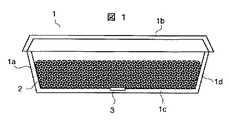
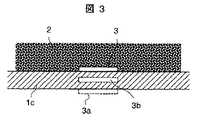
図1は、食品(調理対象物)の加熱または冷却に使用するのに好適な無線タグ付き容器の一実施の形態を示す縦断側面図、図2は、この無線タグ付き容器の底壁部を示す平面図、図3は、同底壁部の縦断側面図である。この実施の形態における無線タグ付き容器は、収容した食品(対象物)を加熱調理または冷却調理するのに好適な弁当箱を例示している。
【0011】
この実施の形態における容器1は、下方に位置して食品2を入れる第1の容器部1a(以下、単に下容器部と呼ぶ)と、この下容器部1aの上方に位置して該下容器部1aの開口を蓋する第2の容器1b(以下、単に蓋と呼ぶ)によって構成し、前記下容器部1aは、無線タグ3を備える。この無線タグ3は、食品2と直に接する下容器部1aの内壁面に設けることが望ましく、より望ましくは、下容器部1aの底壁部1cの内面に設置する構成である。更に、この無線タグ3は、容器1の底壁部1cの略中央部に位置するように設けることが望ましい。もちろん、設置上の制約等で容器1の底壁部1cの中央部に設けられない場合には、底壁部1cにおける周辺部や他の場所に設けても良いし、更には、下容器部1aの側壁部1d等に設けても良い。このように、無線タグ3は、容器1の蓋1bではなく、調理対象の食品2が接する下容器部1a側に設けることが肝心である。
【0012】
なお、無線タグ3を下容器部1aの底壁部1cの内壁面側(食品側)に設けることができない場合には、図3に破線で示すように、参照符号3aで示すように底壁部1cの外壁面に設置したり、参照符号3bで示すように壁内に埋め込んで設置しても良い。
【0013】
このように容器1に設ける無線タグ3は、薄いシート状(薄板状)や立体状の形態に構成されている。シート状の無線タグ3としては、容器1に直に印刷して取り付ける印刷タグや貼り付けるシールタグ等がある。立体状の無線タグ3としては、立方体,円柱体,球体等の無線タグがある。このような立体状の無線タグ3は、外形寸法が1mm以下であることが望ましい。また、コイン状,カード状,スティック状等の無線タグ3を使用することもできる。
【0014】
このように加熱または冷却する調理に使用する容器1に設ける無線タグ3は、特に、加熱調理においては、電子レンジを使用して加熱されることが多いことから、電磁誘導加熱による自らの発熱によって破損しないように保護膜で覆うことが必要である。このような無線タグ3は、例えば、特許文献1に記載された非接触ICタグと同様な保護処理を行って構成することができる。
【0015】
図4は、無線タグ付き容器の他の実施の形態を示す縦断側面図であり、蓋を持たない丼状の容器1を示している。この丼状の容器1においても、無線タグ3は、食品2と接する容器1の底に近い部分(入れられる食品2が接触しない上縁部分1xを避けた部分)の内壁面に設けることが望ましい。このような丼状の容器1では、上部の開口にラップをして使用することも可能である。
【0016】
図5は、無線タグ付き容器1の更に他の実施の形態を示す底部の平面図である。この実施の形態における無線タグ付き容器1は、仕切り壁1eによって内部を仕切って複数の食品収容空間部を形成した容器である。このような無線タグ付き容器1は、弁当の容器として使用するのに好適であり、例えば、食品収容空間部1fをサラダ部(サラダを入れる部分)、食品収容部1gをおかず部(おかずを入れる部分)、食品収容空間部1hを飯部(ご飯を入れる部分)として、それぞれの部分の底壁部に無線タグ3c,3d,3eを設けている。この実施の形態では、各無線タグ3c〜3eは、各食品収容空間部1f〜1hの底壁部の略中央部に設けているが、周辺部や他の場所に偏っていても差し支えない。また、各食品収容空間部1f〜1hのそれぞれに1個の無線タグ3c〜3eを設けているが、1つの食品収容空間部1f〜1hに複数個の無線タグ3を設けても良い。このように1つの容器1に複数個の無線タグ3を設ける構成は、図1〜図3を参照して説明したような大きな底壁部1cを有する容器1において、底壁部1cに適当な間隔で複数個の無線タグ3を設置するように転用することもできる。
【0017】
このように複数個の無線タグ3を設置すると、温度分布を考慮した加熱あるいは冷却調理が可能になるし、1つの無線タグ3が万が一故障しても他の無線タグ3が代役を果たせることになり、信頼性の高い無線タグ付き容器1を実現することができる。温度分布を考慮した加熱あるいは冷却調理を実現するためには、調理器として温度分布を制御できる形態のものを使用するか、各食品収容空間部1f〜1hを分離することができるようにこれらを複数の補助容器の組み合わせによって形成するように構成し、任意の補助容器を取り出して個別に加熱または冷却調理ことができるようにすることが望ましい。
【0018】
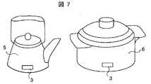
図6および図7は、無線タグ付き容器1の更に他の実施の形態を示す斜視図であり、無線タグ3を設けた皿4,やかん5および鍋6を示している。これら以外にも、フライパン,カップ,茶碗および中華鍋等のあらゆる加熱および冷却用の容器に適用することができる。無線タグ3の設置位置は、図示の例に限る必要はなく、無線タグ3を皿4の表面の絵模様(デザイン)の一部に盛り込んで違和感をなくして美観を確保するようにしても良い。
【0019】
特に、フライパンや天ぷら鍋のように油を使用する料理に用いる容器1は、過熱防止対策が施されていることが望ましく、例えば、無線タグ3の記憶手段に最高加熱温度(例えば300℃)を記憶させておき、容器1の温度が最高加熱温度に達した場合には温度検出手段から無線送信される検出温度情報に基づいて加熱を自動停止するように構成すると良い。
【0020】
図8は、前述した各実施の形態における各種の無線タグ付き容器1に設ける無線タグ3の内部構成と該無線タグ3と通信する情報読み書き手段の内部構成を示すブロック図である。
【0021】
無線タグ3は、記憶手段31と、温度センサ32と、演算回路を主体にして構成したコントロール回路33と、電源生成回路34と、アンテナ35を備える。ここで、記憶手段31は、読み出し専用メモリや書き込み可能なメモリを用途に応じて選択的または組み合わせて構成し、制御処理プログラムや調理条件情報を記憶する。温度センサ32は、感温素子と信号処理回路等で構成し、調理対象食品の温度を検出して検出温度信号を生成する。アンテナ35は、磁性体に導線を巻いたコイル等で構成する。電源生成回路34は、アンテナ35に誘起される高周波電圧を整流して無線タグ3内で使用する直流電源を生成する。コントロール回路33は、前記電源生成回路34で生成した直流電源を使用して作動し、アンテナ35で受信した調理条件情報を記憶手段31に記憶させ、記憶手段31から読み出した調理条件情報および温度センサ32から出力される検出温度信号をアンテナ35から無線送信する制御処理を実行する。
【0022】
情報読み書き手段7は、アンテナ71と、演算回路を主体にして構成したコントロール回路72と、読み取り情報保持回路73と、書き込み情報保持回路74と、電源回路75を備える。ここで、コントロール回路72は、電源回路75から受電して書き込み情報保持回路74に保持している情報をアンテナ71から無線送信し、無線タグ3から無線送信される検出温度情報をアンテナ71を介して取り込んで読み取り情報保持回路74に保持させる制御処理を実行する。また、このコントロール回路72は、食品調理器における制御回路と通信して該制御回路から書き込み情報を取得し、無線タグ3から取得した検出温度情報を制御回路に送信する。
【0023】
無線タグ3と情報読み書き手段7は、離れた状態で無線通信で各種の情報の送信および受信(情報交換)を行う。そして、無線タグ3は、情報読み書き手段7におけるアンテナ71から発射される電磁波による電磁誘導でアンテナ35に誘起される高周波電圧に基づいて電源生成回路34において直流電源を生成する。電磁誘導で利用する電磁波の波長は、kHz帯やMHz帯の長・中波帯であっても良いし、2.45GHz帯のマイクロ波を利用しても良い。
【0024】
ここで、無線タグ3と情報読み書き手段7の間で実行する情報の授受を図9を参照して説明する。図9は、主として、無線タグ3のコントロール回路33と情報読み書き手段7のコントロール回路72が情報授受のために実行する制御処理のフローチャートである。
【0025】
ステップ701
情報読み書き手段7は、アンテナ71から電磁波を送信して無線タグ3のアンテナ35に電磁誘導による高周波電圧を誘起させる。
【0026】
ステップ301
無線タグ3は、情報読み書き手段7のアンテナ71から送信される電磁波によってアンテナ35に誘起した高周波電圧を電源生成回路34によって整流して直流電源を生成する。
【0027】
ステップ302,702
無線タグ3と情報読み書き手段7は、情報の授受を実行する。無線タグ3に新たな調理条件情報を書き込む(記憶させて設定する)場合には、情報読み書き手段7は、書き込み情報保持回路74に保持している調理条件情報をアンテナ71から無線送信し、無線タグ3は、アンテナ35で受信した調理条件情報を記憶手段31に書き込んで記憶する。無線タグ3に記憶している調理条件情報や温度センサ32から出力される検出温度信号を情報読み書き手段7に読み出す場合には、無線タグ3は、無線タグ3に記憶している調理条件情報や温度センサ32から出力される検出温度信号をアンテナ35から無線送信し、情報読み書き手段7は、アンテナ71で受信した調理条件情報や検出温度情報を読み取り情報保持回路73に保持する。
【0028】
次に、前述した無線タグ3を備えた無線タグ付き容器を用いて加熱調理器として電子レンジを用いた加熱調理の実施の形態について説明する。図10は、加熱室内に無線タグ付き容器を収容した電子レンジの模式図、図11は、その機能ブロック図である。
【0029】
電子レンジ8は、枠体81によって囲われた内部空間を隔壁81aで仕切って加熱室81bと制御装置収納部81cを区画している。加熱室81cの下部には、加熱対象物である食品2を入れた無線タグ付き容器1を載置するテーブル82を備え、このテーブル82の下側には、加熱用のマイクロ波を発射する回転アンテナ83を備える。この実施の形態における電子レンジ8は、定置式のテーブル82を設置したターンテーブルレス式電子レンジであるが、ターンテーブルを備えた電子レンジであっても同様に実施することができる。
【0030】
無線タグ付き容器1は、下容器部1aと蓋1bを備え、下部容器1aの底壁部の内壁面に無線タグ3を備える。この実施の形態における無線タグ3は、前述した実施の形態と同様に構成し、調理条件情報として、予め、食品2の仕上温度,食品名,容量,賞味期限および加熱仕様(加熱時間と加熱温度等)等を記憶させている。ここで、無線タグ3は、調理条件情報として、食品2の仕上温度を記憶していることが必須であり、温度情報としては、ワンポイントの仕上温度以外に、加熱仕様として、加熱経過時間とその都度の温度レベルの関係を記憶していると好都合である。
【0031】
また、この無線タグ付き容器1の無線タグ3における電源生成回路34は、電子レンジ8の加熱エネルギー発生手段86におけるマグネトロンが加熱用電磁波として発生する2.45GHz帯のマイクロ波帯の電磁波に感応してアンテナ35に誘起される高周波電圧も入力して直流電源を生成するように構成する。また、利用する波長は、前述したように、kHz帯やMHz帯(例えば、125kHzや13.56MHz)であっても良い。
【0032】
このような無線タグ付き容器1の無線タグ3と情報の授受を行う情報読み書き手段7は、加熱室81bに臨むように隔壁81aに設置する。この実施の形態では、情報読み書き手段7を隔壁81aに設けているが、この情報読み書き手段7は、その他の場所、例えば、加熱室81bの天井壁面,側壁面または底壁面の何れの場所であっても差し支えない。
【0033】
そして、制御装置収納部81cには、操作パネル84と制御回路85と加熱エネルギー発生手段86を収納する。制御回路85は、マイクロプロセッサを主体にして構成し、操作パネル84からの指示入力に従った制御プログラムを実行して、加熱室81b内の無線タグ付き容器1の無線タグ3に新規な調理条件情報を設定する調理条件情報設定制御処理と、加熱室81b内の無線タグ付き容器1の無線タグ3から調理条件情報を読み出すと共に検出温度情報を取得して該調理条件情報と検出温度情報に従って加熱エネルギー発生手段86を制御する加熱調理制御処理を行う。
【0034】
このように構成した電子レンジ8は、操作パネル84を操作して加熱調理を設定し、スタートボタンを押すと、制御回路85は、情報読み書き手段7を作動させて無線タグ付き容器1の無線タグ3から調理条件情報を読み出して該調理条件情報を取得して保持する。そして、この調理条件情報と無線タグ3から無線送信されて情報読み書き手段7で受信した検出温度情報を参照して加熱エネルギー発生手段86を制御する加熱調理制御を実行する。
【0035】
この加熱調理制御では、無線タグ3から無線送信されて情報読み書き手段7で受信した検出温度情報が調理条件に沿うように加熱エネルギー発生手段86を制御し、検出温度情報が仕上温度に達すると加熱エネルギーの発生を停止するように加熱エネルギー発生手段86を制御する。なお、無線タグ3の温度センサ32から出力される検出温度信号は、無線タグ付き容器1内の食品2の温度上昇むらや温度変化(動揺)や該食品2と温度センサ32の間の伝熱状態のバラツキなどにより動揺することがあるので、加熱エネルギーの発生停止は、検出温度情報が複数回(例えば2〜3回)にわたって仕上温度に到達したことを確認したり、検出温度情報が所定時間にわたって継続して仕上温度に到達していることを確認したり、あるいは、最初に仕上温度に到達したことを検出してから所定時間が経過したことを確認したりしてから行う制御方法を採用することが望ましい。
【0036】
図12は、温度センサをもたない無線タグを備えた無線タグ付き容器1を使用しても略同様の加熱調理を実行することができる電子レンジの実施の形態を示す機能ブロック図である。
【0037】
この電子レンジ8は、赤外線温度センサ87を備え、制御回路85は、情報読み書き手段7を介して無線タグ3(温度センサを除いて前述した実施の形態と同様の構成)から調理条件情報を読み出して取得し、赤外線温度センサ87から出力する検出温度信号に基づいて容器1内の食品の温度を検出して加熱エネルギー発生手段86を制御する。勿論、制御回路85は、操作パネル84からの指示入力に基づいて情報読み書き手段7を介して新規な調理条件情報を無線タグ3に記憶させる制御処理を行う。
【0038】
この電子レンジ8を使用する食品の加熱調理は、食品を入れた無線タグ付き容器1を加熱室に入れてドアを閉めると、制御回路85は、情報読み書き手段7を介して無線タグ付き容器1の無線タグ3から調理条件情報を読み出して取得し、この調理条件情報に従って、赤外線温度センサ87から出力する検出温度信号を参照しながら加熱エネルギー発生手段86を制御するようにして行う。
【0039】
そして、加熱調理中に赤外線温度センサ87から出力する検出温度信号の値が仕上温度に達すると、制御回路85は、加熱エネルギーの発生を停止するように加熱エネルギー発生手段86を制御する。なお、赤外線温度センサ87の温度検出値は、仕上温度に瞬間的に達した後に少し下がる場合もあるので、赤外線温度センサ87から出力する検出温度信号に対する前述したような確認を行うことが望ましい。
【0040】
図13は、調理条件情報をもたない無線タグを備えた無線タグ付き容器内の食品を簡単な操作で加熱調理することができる電子レンジの実施の形態を示す機能ブロック図である。
【0041】
この実施の形態における電子レンジ8は、インターネット等の通信手段9を介してサービス会社10から調理条件情報(調理レシピ)を取得し、無線タグ付き容器1の前述した実視の形態と同様な構成の無線タグ3から出力される検出温度情報を参照しながら加熱エネルギー発生手段86を制御し、また、必要に応じて、取得した調理条件情報を無線タグ3に書き込む(記憶させる)構成である。
【0042】
この電子レンジ8の制御回路85は、操作パネル84からの指示入力に基づいて、加熱調理対象の食品2の調理条件情報を通信手段9を介してサービス会社10から取得し、取得した調理条件情報を制御回路85内の記憶部にダウンロードして保持し、前記加熱調理対象食品2を入れる無線タグ付き容器1の無線タグ3と無線通信して該無線タグ3の記憶手段31に前記調理条件情報を記憶させ、または、取得した調理条件情報に基づき、無線タグ付き容器1の無線タグ3出力される該無線タグ3の温度センサ32が検出した検出温度情報を参照して加熱エネルギー発生手段86を制御する加熱調理制御を実行する。
【0043】
この加熱調理制御中に、制御回路85は、無線タグ3から受信する検出温度情報が仕上温度に達すると、加熱エネルギーの発生を停止するように加熱エネルギー発生手段86を制御する。なお、温度センサ32の温度検出には動揺があるので、前述したように確認を行うことが望ましい。
【0044】
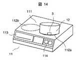
図14は、加熱調理器としてIH(電磁誘導加熱)クッキングヒータを利用した加熱調理の実施の形態を示す機能ブロック図である。
【0045】
この実施の形態におけるIHクッキングヒータ11は、天板111に複数(この実施の形態では2箇所)のIH加熱部112a,112bと、グリル113および操作パネル114を備え、内部に制御回路(図示省略)と前記IH加熱部112a,112bを含む加熱エネルギー発生手段(図示省略)と情報読み書き手段(図示省略)を内蔵する。制御回路と情報読み書き手段は、前述した実施の形態と同様に構成する。
【0046】
このIHクッキングヒータ11のIH加熱部112aに載置する無線タグ付き容器である鍋12は、底部に前述した実施の形態と同様に構成した無線タグ3を備える。
【0047】
このIHクッキングヒータ11の制御回路は、前述した電子レンジの実施の形態と同様に、情報読み書き手段を介して無線タグ3から調理条件情報と検出温度情報を取得して加熱エネルギー発生手段を制御して鍋12を加熱する。
【0048】
このような無線タグ3は、ジャー炊飯器等にも利用することができる。例えば、米と水を入れるジャー炊飯器の内釜に温度センサを備えた無線タグを埋め込み等の方法で取り付けておき、炊飯時には温度センサによる検出温度情報を制御回路に送信してヒータの発熱量を所定の温度特性となるように細かく制御することによりおいしく炊きあげることができるように利用する。更に、ジャー炊飯器では、炊いたご飯を保温することも必要な機能であり、この保温時にも、無線タグから出力する検出温度情報を参照して温度制御することにより、長時間にわたっておいしい状態に保温することが可能となる。
【0049】
次に、このような無線タグを用いた2つのサービスシステムの実施の形態を説明する。
図15は、消費者(家庭)と配食サービス業者を連係させた配食サービスシステムのブロック図である。
【0050】
この実施の形態の配食サービスシステムは、各消費者13から電話やインターネット等の通信手段9を介して配食サービス業者14に任意に注文した食品または予め結んだ契約に基づく受注食品を該配食サービス業者14が無線タグ付き容器に入れて各消費者13に配送し、各消費者13は、配送された食品を加熱調理器である電子レンジ8を使用して加熱調理して食するシステムである。
【0051】
配食サービス業者14は、受注食品を前述したような無線タグ付き容器に入れて各消費者13に配送する。無線タグ付き容器の無線タグは、入れられた食品を加熱調理するための調理条件情報を記憶させた記憶手段と、調理中の温度を検出して検出温度信号を出力する温度センサを備える。
【0052】
無線タグ付き容器で配食を受けた消費者13は、食品を無線タグ付き容器に入れたままの状態で電子レンジ8を使用して加熱調理する。この加熱調理において、電子レンジ8は、無線タグ付き容器の無線タグと無線通信して該無線タグ付き容器に入れられている食品の調理条件情報を取得し、取得した調理条件情報に従った加熱を行うように加熱エネルギー発生手段を制御する。この加熱エネルギー発生手段の制御は、実際の加熱温度が調理条件情報に一致するように、無線タグから出力される検出温度情報を参照しながら実行する。
【0053】
食品を食した後の空の無線タグ付き容器は、配食サービス業者14が回収して再度の配食に利用する。従って、この無線タグ付き容器の無線タグの調理条件情報を記憶させる記憶手段は、調理条件の異なる種々の食品を入れて該食品のための調理条件情報を記憶させて配食することができるように、書き替え可能な形態に構成する。そして、配食サービス業者14は、図示説明は省略するが、前述したような情報読み書き手段と制御回路と操作パネルを備えた書き込み装置を使用して無線タグ付き容器の無線タグに該容器に入れた食品のための新しい調理条件情報を書き込んで記憶させる。
【0054】
また、このような配食サービスシステムは、コンビニエンスストアやスーパーマーケットなどの小売業者と卸売業者を連係させる小売サービスシステムとして実施することができる。この小売業者は、前述した配食サービスシステムにおける消費者13に相当し、卸売業者は、前述した配食サービスシステムにおける配食サービス業者14に相当する。この小売サービスシステムでサービスするのに適した食品は、弁当であり、無線タグ付き容器を弁当箱として使用する。
【0055】
この小売サービスシステムでは、卸売業者が無線タグ付き容器に食品を入れ、この食品の調理条件情報を無線タグの記憶手段に書き込んで記憶させて小売業者に卸す。この無線タグは、温度センサを備える。
【0056】
小売業者は、図9および図11に示したような電子レンジ8を店内に備え、お客が購入した弁当を、お客の希望に応じて店員がそのまま電子レンジ8に入れて該電子レンジ8のスタートボタンを押すだけの操作により、この弁当(入れられた食品)を無線タグに記憶されている調理条件情報に従って、温度センサが検出して出力する検出温度情報を参照しながら、最適な温度に加熱調理してお客に渡すことができる。
【0057】
加熱温度が異なる複数種類の食品を詰め合わせる弁当においては、弁当箱として、図5を参照して説明したような、複数の食品収容空間部1f〜1hを備えた無線タグ付き容器1を使用することが望ましい。
【0058】
以上に説明した実施の形態は、無線タグ付き容器1に入れた食品を加熱調理する構成であるが、次に、無線タグ付き容器1を冷却調理に利用する実施の形態を説明する。この実施の形態では、冷却調理器の一例として、冷蔵庫を用いて説明する。
【0059】
図16は、この実施の形態で冷却調理に使用する冷蔵庫の正面図である。この冷蔵庫15は、主に、冷蔵室151,野菜室152,製氷室153,切替室154および冷凍室155を備える。無線タグ付き容器を使用して冷却調理する部屋は何れの部屋であってもよいが、ここでは、切替え室154を使用して冷却調理する例で説明する。
【0060】
図17は、この実施の形態における冷蔵庫15の前記切替室154とその機能ブロック図である。この冷蔵庫15は、切替室154の内壁に該切替室154内に入れた無線タグ付き容器1の無線タグ3と無線通信する情報読み書き手段7を備え、更に、この切替室154に冷却エネルギーを供給する冷却エネルギー発生手段156と、制御回路157と、操作パネル158を備える。
【0061】
切替室154に入れて冷却調理に使用する無線タグ付き容器1の無線タグ3は、図8に示した実施の形態と同様に、記憶手段31と、温度センサ32と、演算回路を主体にして構成したコントロール回路33と、電源生成回路34と、アンテナ35を備える。
【0062】
情報読み書き手段7は、前述した実施の形態と同様に、制御回路157と協働して、切替室154内に入れられた無線タグ付き容器1の無線タグ3と無線通信して調理条件情報(冷却温度情報)を該無線タグ3に書き込んで記憶させ、無線タグ3の記憶手段31に記憶している調理条件情報(冷却温度情報)を読み出して取得し、無線タグ3が備える温度センサ32から出力される検出温度情報を取得する。
【0063】
制御回路157は、操作パネル158からの指示入力に基づいて、無線タグ3に調理条件情報を記憶させるように前記情報読み書き手段7を制御し、無線タグ3から調理条件情報および検出温度情報を取得するように前記情報読み書き手段7を制御し、情報読み書き手段7が取得した調理条件情報および検出温度情報を参照して冷却エネルギー発生手段156を制御する。
【0064】
このように構成した冷蔵庫15は、冷却調理対象食品を収容して無線タグ3に該食品の調理条件情報を記憶させた無線タグ付き容器1を切替室154に入れて冷却調理をスタートさせると、制御回路157は、情報読み書き手段7を介して無線タグ3から調理条件情報(冷却温度情報)を取得し、この調理条件情報に従って、情報読み書き手段7を介して無線タグ3から取得する検出温度情報を参照しながら冷却エネルギー発生手段156を制御する。そして、検出温度情報が仕上げ温度(冷却温度)に達すると冷却エネルギー発生手段156からの冷却エネルギーの発生を停止させる。
【0065】
この実施の形態で利用する冷却調理器は、冷蔵庫以外に、ワインクーラであっても良いし、家庭用に限らず業務用の冷蔵庫や冷凍庫であっても差し支えないし、更には、加熱手段と冷却手段の両方を備えた調理器であっても良い。
【0066】
図18は、無線タグ付き容器に入れられた食品を加熱または冷却する調理を行うことができる加熱冷却調理器の実施の形態を示す機能ブロック図である。
【0067】
この実施の形態における加熱冷却調理器16は、調理室161と、この調理室161に入れられた無線タグ付き容器1の無線タグ3と無線通信する情報読み書き手段7と、この調理室161に加熱エネルギーを供給する加熱エネルギー発生手段162と、この調理室161に冷却エネルギーを供給する冷却エネルギー発生手段163と、制御回路164と、操作パネル165を備える。
【0068】
調理室161に入れて加熱調理または冷却調理に使用する無線タグ付き容器1の無線タグ3は、図8に示した実施の形態と同様に、記憶手段31と、温度センサ32と、演算回路を主体にして構成したコントロール回路33と、電源生成回路34と、アンテナ35を備える。
【0069】
情報読み書き手段7は、前述した実施の形態と同様に、制御回路164と協働して、調理室161内に入れられた無線タグ付き容器1の無線タグ3と無線通信して調理条件情報(加熱温度情報や冷却温度情報)を該無線タグ3に書き込んで記憶させ、無線タグ3の記憶手段31に記憶している調理条件情報(加熱温度情報や冷却温度情報)を読み出して取得し、無線タグ3が備える温度センサ32から出力される検出温度情報を取得する。
【0070】
制御回路164は、操作パネル165からの指示入力に基づいて、無線タグ3に調理条件情報を記憶させるように前記情報読み書き手段7を制御し、無線タグ3から調理条件情報および検出温度情報を取得するように前記情報読み書き手段7を制御し、情報読み書き手段7が取得した調理条件情報および検出温度情報を参照して加熱エネルギー発生手段162または冷却エネルギー発生手段163を制御する。
【0071】
このように構成した調理器16は、調理対象食品を収容して無線タグ3に該食品の調理条件情報を記憶させた無線タグ付き容器1を調理室161に入れて調理をスタートさせると、制御回路164は、情報読み書き手段7を介して無線タグ3から調理条件情報(調理温度情報)を取得し、この調理条件情報に従って、情報読み書き手段7を介して無線タグ3から取得する検出温度情報を参照しながら加熱エネルギー発生手段162または冷却エネルギー発生手段163を制御する。そして、検出温度情報が仕上げ温度に達すると加熱エネルギー発生手段162または冷却エネルギー発生手段163からのエネルギーの発生を停止させる。
【0072】
本発明の各実施の形態で使用するのに適した無線タグ付き容器1は、無線タグ3の記憶手段31の仕様と有無、温度センサ32の有無によって次のように使用することができる。
【0073】
書き替え不可能な記憶手段31と温度センサ32を備えた無線タグ3を設けた無線タグ付き容器1は、使い捨て使用または同一調理条件の食品を繰り返し入れるように使用して情報読み書き手段7を備えた調理器で調理する用途に好適である。
【0074】
書き替え可能な記憶手段31と温度センサ32を備えた無線タグ3を設けた無線タグ付き容器1は、異なる調理条件の食品を入れて調理条件情報を書き替えて再使用して情報読み書き手段7を備えた調理器で調理する用途に好適である。使い捨て使用または同一調理条件の食品を繰り返し入れるように使用して情報読み書き手段7を備えた調理器で調理する用途にも適することは勿論である。特に、同一の調理条件の食品を入れて加熱する専用の容器として繰り返し使用する用途では、各家庭で任意の特定の食品の調理条件情報(加熱温度)を任意に書き込んで記憶させて使用することができるので便利であり、例えば、特定の食品加熱に専用の皿4,やかん5,鍋6および保温器等に好適である。
【0075】
温度センサ32のみを備えた記憶手段31をもたない無線タグ3を設けた無線タグ付き容器1は、調理器が操作パネルからの指示入力に従って調理条件情報(調理温度や調理時間)を設定し、情報読み書き手段7を介して無線タグ3から取得した検出温度情報を参照して調理する用途に好適である。同一調理条件の食品を繰り返し入れて調理したり、異なる調理条件の食品を繰り返し入れて調理する用途に好適である。
【0076】
書き替え可能な記憶手段31のみを備えた温度センサ32をもたない無線タグ3を設けた無線タグ付き容器1は、異なる調理条件の食品を入れて調理条件情報を書き替えて再使用して図12に示した電子レンジ8のように情報読み書き手段7と赤外線温度センサ87のような温度検出手段を備えた調理器で調理する用途に好適である。書き込んで記憶させた調理条件情報と同一調理条件の食品を繰り返し入れて調理する用途にも適することは勿論である。
【0077】
【発明の効果】
本発明によれば、加熱または冷却する食品を入れる容器に温度センサや調理条件情報を書き替え可能な記憶手段を備えた無線タグを設けた無線タグ付き容器によって食品を加熱または冷却する構成であるので、加熱および/または冷却調理器に適正な調理条件を設定し、無線タグ付き容器の無線タグから送信される検出温度情報を参照しながら設定した調理条件に沿った正確な加熱および/または冷却調理を実行することが容易になる。
【図面の簡単な説明】
【図1】無線タグ付き容器の一実施の形態を示す縦断側面図である。
【図2】図1に示した無線タグ付き容器の底面を示す平面図である。
【図3】図1に示した無線タグ付き容器の底壁部の縦断側面図である。
【図4】無線タグ付き容器の他の実施の形態を示す縦断側面図である。
【図5】無線タグ付き容器の更に他の実施の形態を示す底部の平面図である。
【図6】無線タグ付き容器の更に他の実施の形態を示す斜視図である。
【図7】無線タグ付き容器の更に他の実施の形態を示す斜視図である。
【図8】各実施の形態における各種の無線タグ付き容器に設ける無線タグの内部構成と該無線タグと通信する情報読み書き手段の内部構成を示すブロック図である。
【図9】無線タグのコントロール回路と情報読み書き手段のコントロール回路が情報授受のために実行する制御処理のフローチャートである。
【図10】加熱室内に無線タグ付き容器を収容した電子レンジの模式図である。
【図11】加熱室内に無線タグ付き容器を収容した電子レンジの機能ブロック図である。
【図12】温度センサをもたない無線タグを備えた無線タグ付き容器を収容した赤外線温度センサ付き電子レンジの機能ブロック図である。
【図13】調理条件情報をもたない無線タグを備えた無線タグ付き容器内の食品を簡単な操作で加熱調理することができる電子レンジの実施の形態を示す機能ブロック図である。
【図14】加熱調理器としてIH(電磁誘導加熱)クッキングヒータを利用した加熱調理の実施の形態を示す機能ブロック図である。
【図15】消費者(家庭)と配食サービス業者を連係させた配食サービスシステムのブロック図である。
【図16】無線タグ付き容器を使用して冷却調理する冷蔵庫の正面図である。
【図17】図16に示した冷蔵庫の切替室と機能ブロック図である。
【図18】無線タグ付き容器に入れられた食品を加熱または冷却する調理を行うことができる加熱冷却調理器の実施の形態を示す機能ブロック図である。
【符号の説明】
1…無線タグ付き容器、2…食品,3…無線タグ、31…記憶手段、32…温度センサ、33…コントロール回路、34…電源生成回路、35…アンテナ、7…情報読み書き手段、71…アンテナ、72…コントロール回路、8…電子レンジ、84…操作パネル、85…制御回路、86…加熱エネルギー発生手段。[0001]
TECHNICAL FIELD OF THE INVENTION
The present invention relates to a container with a wireless tag used for cooking (heating, cooling, and the like) of food, and a food cooker for cooking food contained in the container with a wireless tag.
[0002]
[Prior art]
In a conventional food cooking system, a microwave oven (heating cooker) equipped with an infrared temperature sensor for measuring the temperature of the food, and the content of the food recorded in a memory of a non-contact IC tag attached to the food container There is an automatic food cooking system that reads information about cooking conditions and cooking conditions with a microwave oven and optimally cooks food (for example, see Patent Document 1).
[0003]
[Patent Document 1]
JP 2001-317441 A
[0004]
[Problems to be solved by the invention]
A microwave oven that reads cooking condition information of the food from a wireless tag provided in a container containing the food and controls heating of the food while detecting the temperature of the food with an infrared temperature sensor uses a microwave to process the food. The operation of the microwave oven during cooking can be facilitated.
[0005]
However, the infrared temperature sensor provided in the microwave oven has an error in the detected temperature due to the difference in the emissivity of the food to be cooked and the container for containing the food. Further, if a lid or a wrap is provided on a container for containing food, it is difficult to accurately detect the temperature. At the time of continuous heating or steam generation, the detection accuracy is reduced due to the influence. Furthermore, when the food and the container are small, there is a problem that an error occurs in the detected temperature due to the surrounding area other than the container being included in the detection field of view of the infrared temperature sensor. In addition, antifouling measures for the infrared temperature sensor are required.
In addition, since the wireless tag provided in the container stores cooking condition information such as heating temperature information dedicated to the food to be put in, the container storing the cooking condition information is used by putting food of different cooking conditions. Cannot be used as a versatile container.
[0006]
It is an object of the present invention to provide a tableware with a wireless tag that transmits accurate temperature information of a food item being cooked to a food cooker to enable accurate heating and / or cooling.
Another object of the present invention is to provide a food cooker suitable for use as a multi-purpose container in which a container with a wireless tag is used by containing food having different cooking conditions.
[0007]
[Means for Solving the Problems]
The present invention stores a cooking condition information of a food, and in a container with a wireless tag provided with a wireless tag that wirelessly transmits the cooking condition information at the time of cooking in a container that stores the food, the wireless tag detects a temperature. Temperature detecting means for wirelessly transmitting the detected temperature information obtained as described above.
[0008]
The present invention also provides a cooking chamber for storing a container containing food to be cooked, heat energy generating means for applying heating and / or cooling heat energy to the cooking chamber, and a container stored in the cooking chamber. In a food cooker that wirelessly communicates with a wireless tag provided to obtain cooking condition information of food contained in the container and controls the thermal energy generating means based on the cooking condition information,
The control unit includes a detected temperature information obtaining unit that obtains detected temperature information wirelessly transmitted from a wireless tag of a container housed in a cooking chamber, and refers to the obtained detected temperature information and cooking condition information to obtain the heat energy. The generation means is controlled.
[0009]
The present invention also provides a cooking chamber for storing a container containing food to be cooked, heat energy generating means for applying heating and / or cooling heat energy to the cooking chamber, and a container stored in the cooking chamber. In a food cooker that wirelessly communicates with a wireless tag provided to obtain cooking condition information of food contained in the container and controls the thermal energy generating means based on the cooking condition information,
The control unit includes a cooking condition setting unit that wirelessly communicates with a wireless tag of the container and stores cooking condition information in the wireless tag.
[0010]
BEST MODE FOR CARRYING OUT THE INVENTION
An embodiment of the present invention will be described with reference to the drawings.
First, a container with a wireless tag will be described.
FIG. 1 is a longitudinal sectional side view showing an embodiment of a container with a wireless tag suitable for use in heating or cooling a food (object to be cooked). FIG. 2 is a bottom view of the container with a wireless tag. FIG. 3 is a vertical sectional side view of the bottom wall portion. The container with a wireless tag according to this embodiment exemplifies a lunch box suitable for cooking or cooling cooking of a stored food (object).
[0011]
The
[0012]
When the
[0013]
As described above, the
[0014]
Since the
[0015]
FIG. 4 is a longitudinal sectional side view showing another embodiment of the container with a wireless tag, and shows the bowl-shaped
[0016]
FIG. 5 is a plan view of a bottom part showing still another embodiment of the
[0017]
When a plurality of
[0018]
FIG. 6 and FIG. 7 are perspective views showing still another embodiment of the
[0019]
In particular, it is desirable that the
[0020]
FIG. 8 is a block diagram showing an internal configuration of the
[0021]
The
[0022]
The information read / write means 7 includes an
[0023]
The
[0024]
Here, transmission and reception of information executed between the
[0025]
The information read / write means 7 transmits an electromagnetic wave from the
[0026]
The
[0027]
The
[0028]
Next, an embodiment of heating and cooking using a microwave oven as a heating cooker using a container with a wireless tag having the above-described
[0029]
The
[0030]
The
[0031]
In addition, the
[0032]
The information reading and writing means 7 for exchanging information with the
[0033]
Then, the
[0034]
When the
[0035]
In this heating / cooking control, the heating energy generating means 86 is controlled so that the detected temperature information wirelessly transmitted from the
[0036]
FIG. 12 is a functional block diagram illustrating an embodiment of a microwave oven that can execute substantially the same heating and cooking even when using a
[0037]
The
[0038]
In the heating and cooking of food using the
[0039]
Then, when the value of the detected temperature signal output from the
[0040]
FIG. 13 is a functional block diagram showing an embodiment of a microwave oven capable of heating and cooking food in a container with a wireless tag having a wireless tag without cooking condition information by a simple operation.
[0041]
The
[0042]
The
[0043]
During the heating and cooking control, when the detected temperature information received from the
[0044]
FIG. 14 is a functional block diagram showing an embodiment of heating cooking using an IH (electromagnetic induction heating) cooking heater as a heating cooker.
[0045]
The
[0046]
The
[0047]
The control circuit of the
[0048]
Such a
[0049]
Next, an embodiment of two service systems using such wireless tags will be described.
FIG. 15 is a block diagram of a food distribution service system in which a consumer (home) and a food distribution service provider are linked.
[0050]
The food distribution service system according to the present embodiment distributes foods arbitrarily ordered from
[0051]
The food
[0052]
The
[0053]
The empty tag-equipped container after eating the food is collected by the food
[0054]
Such a meal distribution service system can be implemented as a retail service system that links a retailer such as a convenience store or a supermarket with a wholesaler. This retailer corresponds to the
[0055]
In this retail service system, a wholesaler puts food in a container with a wireless tag, writes cooking condition information of the food in storage means of the wireless tag, stores the information, and wholesales the retailer. This wireless tag includes a temperature sensor.
[0056]
The retailer prepares the
[0057]
In a lunch box in which a plurality of types of foods having different heating temperatures are packed, as a lunch box, a
[0058]
In the embodiment described above, the food placed in the
[0059]
FIG. 16 is a front view of a refrigerator used for cooling cooking in this embodiment. The
[0060]
FIG. 17 is a functional block diagram of the
[0061]
The
[0062]
The information reading / writing means 7 communicates with the
[0063]
The
[0064]
The
[0065]
The cooling cooker used in this embodiment may be a wine cooler other than a refrigerator, or may be a refrigerator or a freezer for business use, not limited to home use. A cooker provided with both means may be used.
[0066]
FIG. 18 is a functional block diagram showing an embodiment of a heating / cooling cooker capable of performing cooking for heating or cooling food placed in a container with a wireless tag.
[0067]
The heating /
[0068]
As in the embodiment shown in FIG. 8, the
[0069]
The information read /
[0070]
The
[0071]
When the
[0072]
The wireless tag-equipped
[0073]
The
[0074]
The
[0075]
In the
[0076]
The
[0077]
【The invention's effect】
ADVANTAGE OF THE INVENTION According to this invention, it is a structure which heats or cools food by the container with a wireless tag provided with the wireless tag provided with the temperature sensor and the storage means which can rewrite cooking condition information in the container which contains the food to be heated or cooled. Therefore, correct cooking conditions are set in the heating and / or cooling cooker, and accurate heating and / or cooling according to the set cooking conditions while referring to the detected temperature information transmitted from the wireless tag of the container with the wireless tag. It becomes easy to perform cooking.
[Brief description of the drawings]
FIG. 1 is a vertical sectional side view showing an embodiment of a container with a wireless tag.
FIG. 2 is a plan view showing a bottom surface of the container with a wireless tag shown in FIG. 1;
FIG. 3 is a vertical side view of a bottom wall portion of the container with a wireless tag shown in FIG. 1;
FIG. 4 is a longitudinal sectional side view showing another embodiment of a container with a wireless tag.
FIG. 5 is a plan view of a bottom portion showing still another embodiment of the container with a wireless tag.
FIG. 6 is a perspective view showing still another embodiment of a container with a wireless tag.
FIG. 7 is a perspective view showing still another embodiment of a container with a wireless tag.
FIG. 8 is a block diagram showing an internal configuration of a wireless tag provided in various types of containers with wireless tags and an internal configuration of information reading / writing means for communicating with the wireless tag in each embodiment.
FIG. 9 is a flowchart of a control process executed by the control circuit of the wireless tag and the control circuit of the information reading / writing means for information exchange.
FIG. 10 is a schematic view of a microwave oven in which a container with a wireless tag is accommodated in a heating chamber.
FIG. 11 is a functional block diagram of a microwave oven containing a container with a wireless tag in a heating chamber.
FIG. 12 is a functional block diagram of a microwave oven with an infrared temperature sensor that houses a container with a wireless tag provided with a wireless tag without a temperature sensor.
FIG. 13 is a functional block diagram showing an embodiment of a microwave oven that can heat and cook food in a wireless tag-equipped container provided with a wireless tag having no cooking condition information by a simple operation.
FIG. 14 is a functional block diagram showing an embodiment of heating cooking using an IH (electromagnetic induction heating) cooking heater as a heating cooker.
FIG. 15 is a block diagram of a food distribution service system in which a consumer (home) and a food distribution service provider are linked.
FIG. 16 is a front view of a refrigerator that performs cooling cooking using a container with a wireless tag.
17 is a switching room and a functional block diagram of the refrigerator shown in FIG.
FIG. 18 is a functional block diagram showing an embodiment of a heating / cooling cooker capable of performing cooking for heating or cooling food placed in a container with a wireless tag.
[Explanation of symbols]
DESCRIPTION OF
Claims (6)
Translated fromJapanese前記無線タグは、温度を検出して得た検出温度情報を無線送信する温度検出手段を備えたことを特徴とする無線タグ付き容器。In a container with a wireless tag provided with a wireless tag that stores cooking condition information of food and wirelessly transmits the cooking condition information during cooking to a container that stores the food,
A container with a wireless tag, wherein the wireless tag includes a temperature detecting unit for wirelessly transmitting detected temperature information obtained by detecting a temperature.
前記制御手段は、調理室に収容された容器の無線タグから無線送信される検出温度情報を取得する検出温度情報取得手段を備え、取得した検出温度情報と調理条件情報を参照して前記熱エネルギー発生手段を制御することを特徴とする食品調理器。A cooking chamber containing a container containing food to be cooked, heat energy generating means for applying heating and / or cooling heat energy to the cooking chamber, and a radio provided in the container stored in the cooking chamber In a food cooker that wirelessly communicates with a tag and obtains cooking condition information of food contained in the container, and controls the thermal energy generating unit based on the cooking condition information,
The control unit includes a detected temperature information obtaining unit that obtains detected temperature information wirelessly transmitted from a wireless tag of a container housed in a cooking chamber, and refers to the obtained detected temperature information and cooking condition information to obtain the heat energy. A food cooker characterized by controlling generation means.
前記制御手段は、前記容器の無線タグと無線通信して該無線タグに調理条件情報を記憶させる調理条件設定手段を備えたことを特徴とする食品調理器。A cooking chamber containing a container containing food to be cooked, heat energy generating means for applying heating and / or cooling heat energy to the cooking chamber, and a radio provided in the container stored in the cooking chamber In a food cooker that wirelessly communicates with a tag and obtains cooking condition information of food contained in the container, and controls the thermal energy generating unit based on the cooking condition information,
A food cooker comprising: a cooking condition setting unit configured to wirelessly communicate with a wireless tag of the container and store cooking condition information in the wireless tag.
Priority Applications (1)
| Application Number | Priority Date | Filing Date | Title |
|---|---|---|---|
| JP2002303900AJP2004138331A (en) | 2002-10-18 | 2002-10-18 | Containers and food cookers with wireless tags |
Applications Claiming Priority (1)
| Application Number | Priority Date | Filing Date | Title |
|---|---|---|---|
| JP2002303900AJP2004138331A (en) | 2002-10-18 | 2002-10-18 | Containers and food cookers with wireless tags |
Publications (1)
| Publication Number | Publication Date |
|---|---|
| JP2004138331Atrue JP2004138331A (en) | 2004-05-13 |
Family
ID=32451495
Family Applications (1)
| Application Number | Title | Priority Date | Filing Date |
|---|---|---|---|
| JP2002303900AWithdrawnJP2004138331A (en) | 2002-10-18 | 2002-10-18 | Containers and food cookers with wireless tags |
Country Status (1)
| Country | Link |
|---|---|
| JP (1) | JP2004138331A (en) |
Cited By (21)
| Publication number | Priority date | Publication date | Assignee | Title |
|---|---|---|---|---|
| JP2006031435A (en)* | 2004-07-16 | 2006-02-02 | K-Mix:Kk | Food distribution service system |
| JP2006153434A (en)* | 2004-11-02 | 2006-06-15 | Matsushita Electric Ind Co Ltd | High frequency heating apparatus, heating information management system and program thereof |
| JP2006153435A (en)* | 2004-11-02 | 2006-06-15 | Matsushita Electric Ind Co Ltd | High frequency heating apparatus, heating information management system and program thereof |
| JP2006156006A (en)* | 2004-11-26 | 2006-06-15 | Matsushita Electric Ind Co Ltd | Cooking apparatus and program thereof |
| JP2006153430A (en)* | 2004-10-25 | 2006-06-15 | Matsushita Electric Ind Co Ltd | Cooker and its program |
| JP2006153432A (en)* | 2004-11-04 | 2006-06-15 | Matsushita Electric Ind Co Ltd | Cooker and information medium and program |
| JP2006214644A (en)* | 2005-01-07 | 2006-08-17 | Matsushita Electric Ind Co Ltd | Storage |
| JP2006344054A (en)* | 2005-06-09 | 2006-12-21 | Fujitsu Ltd | Storage medium control apparatus, storage medium control method, and computer program |
| JP2007134128A (en)* | 2005-11-09 | 2007-05-31 | Sanki Shoji:Kk | Induction heating cooking equipment and food packing body |
| JP2007164528A (en)* | 2005-12-14 | 2007-06-28 | Fujitsu Ltd | RFID tag |
| KR100871492B1 (en) | 2007-01-17 | 2008-12-05 | 엘지전자 주식회사 | Food Information Books, Food Cooking Guide Systems and Methods |
| US7535366B2 (en) | 2006-12-13 | 2009-05-19 | 3M Innovative Properties Company | Microwaveable radio frequency identification tags |
| JP2009187965A (en)* | 2009-05-27 | 2009-08-20 | Panasonic Corp | Cooking apparatus and program thereof |
| JP2014086323A (en)* | 2012-10-24 | 2014-05-12 | Mitsubishi Electric Corp | Heating cooker, cooking instrument, and heating cooking system |
| US8759725B2 (en) | 2006-12-22 | 2014-06-24 | Semiconductor Energy Laboratory Co., Ltd. | Temperature control device and article having the same |
| US8820624B2 (en) | 2007-01-11 | 2014-09-02 | Lg Electronics Inc. | Cooking information book, cooking system, cooking method, and using method for the cooking system |
| US10257884B2 (en) | 2007-09-13 | 2019-04-09 | Semiconductor Energy Laboratory Co., Ltd. | Semiconductor device and heating system |
| JP2020512171A (en)* | 2017-03-28 | 2020-04-23 | インダクティブ インテリジェンス,リミティド ライアビリティ カンパニー | Smart packaging, systems and methods |
| US10856372B2 (en) | 2015-04-10 | 2020-12-01 | Danmarks Tekniske Universitet | Medical preparation container comprising microwave powered sensor assembly |
| WO2022064806A1 (en)* | 2020-09-25 | 2022-03-31 | パナソニックIpマネジメント株式会社 | Portable article storage device and household electrical appliance cooking system |
| CN116018490B (en)* | 2020-09-25 | 2025-10-14 | 松下知识产权经营株式会社 | Portable storage device and household cooking system |
Citations (7)
| Publication number | Priority date | Publication date | Assignee | Title |
|---|---|---|---|---|
| JPH03192684A (en)* | 1989-12-20 | 1991-08-22 | Matsushita Electric Ind Co Ltd | Pan for induction heating cooker and induction heating cooker |
| WO2001019141A1 (en)* | 1999-09-07 | 2001-03-15 | Thermal Solutions, Inc. | Method and apparatus for magnetic induction heating using radio frequency identification of object to be heated |
| JP2001317741A (en)* | 2000-02-28 | 2001-11-16 | Dainippon Printing Co Ltd | Automatic food cooking system and microwave oven |
| JP2002022177A (en)* | 2000-07-12 | 2002-01-23 | Dainippon Printing Co Ltd | Cooking and food information distribution and management system |
| JP2002029615A (en)* | 2000-07-14 | 2002-01-29 | Hitachi Maxell Ltd | Article management system and article management method |
| JP2002049905A (en)* | 2000-08-03 | 2002-02-15 | Dainippon Printing Co Ltd | Package with contactless data carrier and product information management method |
| JP2002156117A (en)* | 2000-11-17 | 2002-05-31 | Matsushita Electric Ind Co Ltd | Method for providing a heating pattern of lunch-like food by information processing device, and information processing device |
- 2002
- 2002-10-18JPJP2002303900Apatent/JP2004138331A/ennot_activeWithdrawn
Patent Citations (7)
| Publication number | Priority date | Publication date | Assignee | Title |
|---|---|---|---|---|
| JPH03192684A (en)* | 1989-12-20 | 1991-08-22 | Matsushita Electric Ind Co Ltd | Pan for induction heating cooker and induction heating cooker |
| WO2001019141A1 (en)* | 1999-09-07 | 2001-03-15 | Thermal Solutions, Inc. | Method and apparatus for magnetic induction heating using radio frequency identification of object to be heated |
| JP2001317741A (en)* | 2000-02-28 | 2001-11-16 | Dainippon Printing Co Ltd | Automatic food cooking system and microwave oven |
| JP2002022177A (en)* | 2000-07-12 | 2002-01-23 | Dainippon Printing Co Ltd | Cooking and food information distribution and management system |
| JP2002029615A (en)* | 2000-07-14 | 2002-01-29 | Hitachi Maxell Ltd | Article management system and article management method |
| JP2002049905A (en)* | 2000-08-03 | 2002-02-15 | Dainippon Printing Co Ltd | Package with contactless data carrier and product information management method |
| JP2002156117A (en)* | 2000-11-17 | 2002-05-31 | Matsushita Electric Ind Co Ltd | Method for providing a heating pattern of lunch-like food by information processing device, and information processing device |
Cited By (26)
| Publication number | Priority date | Publication date | Assignee | Title |
|---|---|---|---|---|
| JP2006031435A (en)* | 2004-07-16 | 2006-02-02 | K-Mix:Kk | Food distribution service system |
| JP2006153430A (en)* | 2004-10-25 | 2006-06-15 | Matsushita Electric Ind Co Ltd | Cooker and its program |
| JP2006153434A (en)* | 2004-11-02 | 2006-06-15 | Matsushita Electric Ind Co Ltd | High frequency heating apparatus, heating information management system and program thereof |
| JP2006153435A (en)* | 2004-11-02 | 2006-06-15 | Matsushita Electric Ind Co Ltd | High frequency heating apparatus, heating information management system and program thereof |
| JP2006153432A (en)* | 2004-11-04 | 2006-06-15 | Matsushita Electric Ind Co Ltd | Cooker and information medium and program |
| JP2006156006A (en)* | 2004-11-26 | 2006-06-15 | Matsushita Electric Ind Co Ltd | Cooking apparatus and program thereof |
| JP2006214644A (en)* | 2005-01-07 | 2006-08-17 | Matsushita Electric Ind Co Ltd | Storage |
| JP2006344054A (en)* | 2005-06-09 | 2006-12-21 | Fujitsu Ltd | Storage medium control apparatus, storage medium control method, and computer program |
| JP2007134128A (en)* | 2005-11-09 | 2007-05-31 | Sanki Shoji:Kk | Induction heating cooking equipment and food packing body |
| JP2007164528A (en)* | 2005-12-14 | 2007-06-28 | Fujitsu Ltd | RFID tag |
| US7535366B2 (en) | 2006-12-13 | 2009-05-19 | 3M Innovative Properties Company | Microwaveable radio frequency identification tags |
| US9629205B2 (en) | 2006-12-22 | 2017-04-18 | Semiconductor Energy Laboratory Co., Ltd. | Temperature control device |
| US8759725B2 (en) | 2006-12-22 | 2014-06-24 | Semiconductor Energy Laboratory Co., Ltd. | Temperature control device and article having the same |
| US8820624B2 (en) | 2007-01-11 | 2014-09-02 | Lg Electronics Inc. | Cooking information book, cooking system, cooking method, and using method for the cooking system |
| KR100871492B1 (en) | 2007-01-17 | 2008-12-05 | 엘지전자 주식회사 | Food Information Books, Food Cooking Guide Systems and Methods |
| US10257884B2 (en) | 2007-09-13 | 2019-04-09 | Semiconductor Energy Laboratory Co., Ltd. | Semiconductor device and heating system |
| JP2009187965A (en)* | 2009-05-27 | 2009-08-20 | Panasonic Corp | Cooking apparatus and program thereof |
| JP2014086323A (en)* | 2012-10-24 | 2014-05-12 | Mitsubishi Electric Corp | Heating cooker, cooking instrument, and heating cooking system |
| US10856372B2 (en) | 2015-04-10 | 2020-12-01 | Danmarks Tekniske Universitet | Medical preparation container comprising microwave powered sensor assembly |
| US11006487B2 (en) | 2015-04-10 | 2021-05-11 | Danmarks Tekniske Universitet | Microwave powered sensor assembly for microwave ovens |
| JP2020512171A (en)* | 2017-03-28 | 2020-04-23 | インダクティブ インテリジェンス,リミティド ライアビリティ カンパニー | Smart packaging, systems and methods |
| WO2022064806A1 (en)* | 2020-09-25 | 2022-03-31 | パナソニックIpマネジメント株式会社 | Portable article storage device and household electrical appliance cooking system |
| JP2022053679A (en)* | 2020-09-25 | 2022-04-06 | パナソニックIpマネジメント株式会社 | Portable article storage device and household electrical appliance cooking system |
| CN116018490A (en)* | 2020-09-25 | 2023-04-25 | 松下知识产权经营株式会社 | Portable storage and appliance cooking systems |
| JP7417948B2 (en) | 2020-09-25 | 2024-01-19 | パナソニックIpマネジメント株式会社 | Portable article storage equipment and appliance cooking systems |
| CN116018490B (en)* | 2020-09-25 | 2025-10-14 | 松下知识产权经营株式会社 | Portable storage device and household cooking system |
Similar Documents
| Publication | Publication Date | Title |
|---|---|---|
| JP2004138331A (en) | Containers and food cookers with wireless tags | |
| US20220053971A1 (en) | Portable cooler container with active temperature control | |
| US8193474B2 (en) | Smart sensing oven | |
| EP2822428B1 (en) | Cooking appliance | |
| ES2233264T3 (en) | COOKING SYSTEM AND OVEN USED IN THE. | |
| ES2384097T3 (en) | Intelligent induction cooker controlled by RFDI and method for cooking and heating | |
| EP2879555B1 (en) | Sous vide cooking device | |
| AU2002251013B2 (en) | Apparatus and method of rapidly heating a packaged food product | |
| US20160198885A1 (en) | Intelligent Cooking Apparatuses and Methods | |
| EP1174667A1 (en) | Automatic refrigerator system, refrigerator, automatic cooking system, and microwave oven | |
| CN108700301A (en) | Integrated and compartment system for food storage and processing | |
| US20220322870A1 (en) | Food heating system and method for pick-up or delivery | |
| US20200345172A1 (en) | Countertop with induction hob | |
| JP2021018781A (en) | Consumables processing system | |
| US20210042130A1 (en) | Cooking management method, cooking management system, cooking management server and cooking appliance | |
| CN107529921A (en) | For receiving the cooking apparatus of at least one cooking container | |
| JP2019000611A (en) | Device and method for automatic pod cooking with temperature and water control | |
| JP2005242629A (en) | Non-contact information storage medium and cooking equipment | |
| JP4241711B2 (en) | Cooker | |
| JP4296932B2 (en) | Electrical equipment | |
| KR102025857B1 (en) | Paper container for heating | |
| CN215820554U (en) | Heating appliance | |
| JPS6222611A (en) | Heating thermostatic service dish | |
| CN209235833U (en) | A Smart Pot for Digital Cooking | |
| JP2018138110A (en) | Hot water cooking device and control method thereof |
Legal Events
| Date | Code | Title | Description |
|---|---|---|---|
| A621 | Written request for application examination | Free format text:JAPANESE INTERMEDIATE CODE: A621 Effective date:20050311 | |
| A131 | Notification of reasons for refusal | Free format text:JAPANESE INTERMEDIATE CODE: A131 Effective date:20070427 | |
| A521 | Written amendment | Free format text:JAPANESE INTERMEDIATE CODE: A523 Effective date:20070621 | |
| A131 | Notification of reasons for refusal | Free format text:JAPANESE INTERMEDIATE CODE: A131 Effective date:20071211 | |
| A761 | Written withdrawal of application | Free format text:JAPANESE INTERMEDIATE CODE: A761 Effective date:20080117 |