JP2004135084A - Electric / electronic device, charging device, charging method, and charging program - Google Patents
Electric / electronic device, charging device, charging method, and charging programDownload PDFInfo
- Publication number
- JP2004135084A JP2004135084AJP2002297886AJP2002297886AJP2004135084AJP 2004135084 AJP2004135084 AJP 2004135084AJP 2002297886 AJP2002297886 AJP 2002297886AJP 2002297886 AJP2002297886 AJP 2002297886AJP 2004135084 AJP2004135084 AJP 2004135084A
- Authority
- JP
- Japan
- Prior art keywords
- electric
- electronic device
- charging
- power
- information
- Prior art date
- Legal status (The legal status is an assumption and is not a legal conclusion. Google has not performed a legal analysis and makes no representation as to the accuracy of the status listed.)
- Pending
Links
Images


Landscapes
- Meter Arrangements (AREA)
Abstract
Translated fromJapaneseDescription
Translated fromJapanese【0001】
【発明の属する技術分野】
本発明は、電気電子装置・課金装置・課金方法・課金プログラムに関する。
【0002】
【従来の技術】
複写機、プリンタ、ファクシミリその他の印刷機器は、リースやレンタルという形で取引されることが多い。この場合、これらの印刷機器の課金金額は、印刷枚数やトナーボックス使用個数等に基づいて算定されることが多い。いわゆる、パフォーマンスチャージである。
【0003】
これらの印刷機器の課金金額を、通信回線を利用して管理すれば便利である。
例えば、特開2001−34446号公報に記載の課金システムでは、プリンタの課金金額を印刷枚数に基づいて算定して、且つ、プリンタの課金金額を通信回線を利用して管理する。
【0004】
【特許文献1】
特開2001−34446号公報。
【0005】
【発明が解決しようとする課題】
さて、用紙節約やトナー節約等の「省資源」だけでなく電力節約等の「省エネルギ」も重大な関心事である。しかし、特開2001−34446号公報に記載の課金システムでは、プリンタの課金金額を印刷枚数に基づいて算定しており、プリンタの不使用時にプリンタの電源をオフにして省エネルギを実践したところで、プリンタの課金金額は特別安価になる訳ではない。すなわち、当該課金システムは省エネルギにあまり貢献しない。
【0006】
また、リースやレンタルという形で取引される機器は、複写機、プリンタ、ファクシミリその他の印刷機器に限らない。しかし、特開2001−34446号公報に記載の課金システムでは、プリンタの課金金額を印刷枚数に基づいて算定しており、課金金額を印刷枚数に基づいて算定することが困難又は不可能な機器(印刷工程を伴わない機器等)には、適用困難又は適用不可能である。
【0007】
したがって、本発明は、課金金額を通信回線を利用して管理する課金システムであって、省エネルギに貢献できて、且つ、電力を消費して稼動する電気電子装置に広く適用できる課金システムを実現することを課題とする。
【0008】
【課題を解決するための手段】
請求項1に記載の発明(電気電子装置)は、電力を消費して稼動する電気電子装置であって、当該電気電子装置の課金金額を算定するための課金パラメータを測定する測定手段と、前記測定手段により測定された前記課金パラメータに係る情報を通信回線へと送信する送信手段とを備え、前記課金パラメータは当該電気電子装置の電力消費量又は電力源接続時間である。
【0009】
請求項2に記載の発明(電気電子装置)は、電力を消費して稼動する電気電子装置であって、当該電気電子装置の課金金額を算定するための課金パラメータを測定する測定手段と、前記測定手段により測定された前記課金パラメータに係る情報を通信回線へと送信する送信手段とを備え、前記課金パラメータは当該電気電子装置の電力源であるバッテリの交換回数、バッテリの残容量、発電装置に係る発電材料パックの交換回数、発電装置に係る発電材料の残容量、燃料電池の交換回数、燃料電池に係る燃料パックの交換回数、又は燃料電池に係る燃料の残容量である。
【0010】
請求項3に記載の発明(課金装置)は、請求項1又は2に記載の電気電子装置により送信された前記課金パラメータに係る情報を通信回線から受信する受信手段と、前記受信手段により受信された前記課金パラメータに係る情報に基づいて当該電気電子装置の課金金額を算定する算定手段とを備える。
【0011】
請求項4に記載の発明(課金方法)は、請求項1又は2に記載の電気電子装置により送信された前記課金パラメータに係る情報を通信回線から受信する受信段階と、前記受信段階により受信された前記課金パラメータに係る情報に基づいて当該電気電子装置の課金金額を算定する算定段階とを備える。
【0012】
請求項5に記載の発明(課金プログラム)は、請求項1又は2に記載の電気電子装置により送信された前記課金パラメータに係る情報を通信回線から受信する受信段階と、前記受信段階により受信された前記課金パラメータに係る情報に基づいて当該電気電子装置の課金金額を算定する算定段階とを備える課金方法をコンピュータに実行させる。
【0013】
請求項1又は2に記載の発明(電気電子装置)は、当該電気電子装置の課金金額を算定するための課金パラメータを測定して、その課金パラメータに係る情報を通信回線へと送信することにより、その課金パラメータに係る情報を通信回線から受信させて、その課金パラメータに係る情報に基づいて当該電気電子装置の課金金額を算定させるなどして、当該電気電子装置の課金金額を通信回線を利用して管理させることができる。
【0014】
請求項3乃至5のいずれか1項に記載の発明(課金装置・課金方法・課金プログラム)は、請求項1又は2に記載の電気電子装置により送信された課金パラメータに係る情報を通信回線から受信して、その課金パラメータに係る情報に基づいて当該電気電子装置の課金金額を算定することにより、当該電気電子装置の課金金額を通信回線を利用して管理することができる。
【0015】
上記「課金パラメータ」は、当該電気電子装置の電力消費量又は電力源接続時間、又は、当該電気電子装置の電力源であるバッテリの交換回数、バッテリの残容量、発電装置に係る発電材料パックの交換回数、発電装置に係る発電材料の残容量、燃料電池の交換回数、燃料電池に係る燃料パックの交換回数、又は燃料電池に係る燃料の残容量であるため、上記のような「課金管理」は、省エネルギに貢献できて、且つ、電力を消費して稼動する電気電子装置に広く適用できる。
【0016】
すなわち、本発明は、課金金額を通信回線を利用して管理する課金システムであって、省エネルギに貢献できて、且つ、電力を消費して稼動する電気電子装置に広く適用できる課金システムを実現することを可能にする。
【0017】
【発明の実施の形態】
本発明の実施の形態について説明する。
【0018】
図1は、本発明に係る課金システムの例を表す。図1の課金システムは、本発明の実施の形態の例である電気電子装置11と、本発明の実施の形態の例である課金装置12と、これらを接続する通信回線13により構成される。図1の課金システムにおいて、電気電子装置11は1台しかなくても複数台あってもよく、通信回線13は汎用回線でも専用回線でもよい。
【0019】
電気電子装置11は、電力を消費して稼動する装置であり、例えば、複写機、プリンタ、ファクシミリ、スキャナ、コンピュータその他のOA機器である。電気電子装置11は、課金パラメータを測定する測定装置14と、その課金パラメータに係る情報を通信回線13へと送信する送信装置15とを備える。
【0020】
課金装置12は、電気電子装置11の課金金額を通信回線13を利用して管理する装置であり、例えば、コンピュータである。課金装置12は、電気電子装置11により送信された課金パラメータに係る情報を通信回線13から受信する受信装置16と、その課金パラメータに係る情報に基づいて電気電子装置11の課金金額を算定する算定装置17とを備える。
【0021】
電気電子装置11と課金装置12の間では、電気電子装置11の装置情報や、課金パラメータに係る情報をはじめとする電気電子装置11の利用情報が授受される。装置情報や利用情報は、送信装置15が通信回線13へと送信して、受信装置16が通信回線13から受信する。算定装置17は、電気電子装置11に係る装置情報とユーザ情報を保持することが可能であり、受信装置16が利用情報を受信すると算定装置17はこれに基づいてユーザ情報を更新する。
【0022】
課金パラメータは、電気電子装置11の課金金額を算定するために測定される値であり、例えば、電気電子装置11の電力消費量又は電力源接続時間、又は、電気電子装置11の電力源であるバッテリの交換回数、バッテリの残容量、発電装置に係る発電材料パックの交換回数、発電装置に係る発電材料の残容量、燃料電池の交換回数、燃料電池に係る燃料パックの交換回数、又は燃料電池に係る燃料の残容量である。図1の課金システムは、これらの値を課金パラメータとするため、省エネルギに貢献できて、且つ、電力を消費して稼動する電気電子装置に広く適用できる。課金パラメータの詳細については、実施例にて説明する。
【0023】
図2は、算定装置17の例を表す。図2の算定装置17は、CPU(中央演算処理装置)21と、ROM(読み出し専用メモリ)22と、RAM(読み出し書き込みメモリ)23と、FDD(フロッピディスク(登録商標)ドライブ)24と、HDD(ハードディスクドライブ)25と、キーボード26と、ディスプレイ27と、システムバス28とを備える。
【0024】
CPU21は、HDD25に格納されたOS(オペレーショナルシステム)や課金金額算定プログラム等の実行や、ROM22に格納された基本I/Oプログラム等の実行や、RAM23をメインメモリやワークエリアとして機能させて、各種プログラムの実行に必要な情報を当該RAM23に一時的に格納させる制御を行う。
【0025】
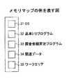
図3は、課金金額算定プログラム33がHDD25からRAM23へとロードされて実行可能となった状態のメモリマップの例を表す。算定装置17の電源がオンにされると、OS31や基本I/Oプログラム32がそれぞれHDD25やROM22からRAM23へとロードされる。基本I/Oプログラム32は、OS31の動作を開始させるIPL(初期プログラムローディング)機能等を有しているプログラムが入っている領域である。そして、課金金額算定プログラム33や関連データ34が展開され、CPU21が課金金額算定プログラム33を実行するワークエリア35が設けられている。
【0026】
ここで、図1の課金システムに関して、電気電子装置11がOA機器である場合を例にとり、課金管理のビジネスモデルの例について説明する。
【0027】
当該OA機器は、例えば、製造会社により製造され、製造会社から販売会社へと卸され、販売会社により官公庁、企業、教育機関等のユーザにリース又はレンタルされる。この際に締結されるリース契約又はレンタル契約により、課金金額の算定基準等が定められる。こうしてユーザのオフィス等に設置された当該OA機器(電気電子装置11)は、通信回線13に接続されることにより、課金装置12に接続されることになる。
【0028】
OA機器11と課金装置12の間では、課金パラメータに係る情報をはじめとするOA機器11の利用情報が授受される。利用情報は、送信装置15が通信回線13へと送信して、受信装置16が通信回線13から受信する。
【0029】
利用情報は、例えば毎月1回等の所定サイクルで授受される。利用情報は、受信装置16により通信回線13から受信され、図2のシステムバス28を介してRAM23に一時的に格納され、HDD25に転送されて格納される。HDD25に格納された課金パラメータに係る情報は、課金金額算定プログラムの稼動時に呼び出され、その他の利用情報や装置情報も適宜加味しつつ、CPU21がこの課金パラメータに係る情報に基づいてOA機器11の課金金額を算定する。CPU21により算定された課金金額は、再びHDD25に格納される。HDDに格納された課金金額は、請求金額算定プログラムの稼動時に再び呼び出され、ディスプレイ27に表示される。こうして、OA機器11の販売会社の従業員は、OA機器11のユーザに対して支払請求する課金金額を知ることができる。
【0030】
OA機器11の販売会社の従業員は、例えば毎月1回等の所定サイクルで、OA機器11のユーザに対してこの課金金額の支払いを請求する。OA機器11のユーザは、OA機器11の販売会社に対してこの課金金額の支払いを実行する。
OA機器11の製造会社と販売会社は、予め取り決めておいた各自の取り分等を考慮して、支払われた金額を分配する。
【0031】
以上、図1の課金システムに関して、課金装置12の算定装置17の例について図2にて説明した。以下、図1の課金システムに関して、電気電子装置11の測定装置14の例について図4〜図12(第1〜第9実施例)にて説明する。
【0032】
(第1実施例)
図4は、第1実施例を表す。第1実施例では、電気電子装置11は複写機、通信回線13は電話回線、測定装置14は電力消費量測定装置、送信装置15はモデムである。
【0033】
複写機11の電力源は家庭用電源41である。複写機11は、家庭用電源41から電力を取得するためのコンセント42とコード43とを備え、当該電力を消費して稼動する。電力消費量測定装置14は、例えばデジタルパワーメータであり、ここではコード43の途中に設けられている。モデム15は、ここでは電力消費量測定装置14に直接取り付けられている。
【0034】
ユーザが家庭用電源41にコンセント42を挿入すると、複写機11に電力が供給され、ユーザが複写機11のスイッチをオンにすると、複写機11は電力を消費して稼動する。そして、電力消費量測定装置14が、課金パラメータとして複写機11の消費電力量を測定する。さらに、モデム15は、例えば毎月1回、電力消費量測定装置14により測定された当月分の「複写機11の電力消費量」に係る情報を電話回線13へと送信する。例えば、kWh単位で表した電力消費量そのものや電力消費量をポイント化した値等を送信する。
【0035】
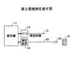
(第2実施例)
図5は、第2実施例を表す。第2実施例では、電気電子装置11は複写機、通信回線13は電話回線、測定装置14は電力源接続時間測定装置、送信装置15はモデムである。
【0036】
複写機11の電力源は家庭用電源41である。複写機11は、家庭用電源41から電力を取得するためのコンセント42とコード43とを備え、当該電力を消費して稼動する。電力源接続時間測定装置14は、例えば通電タイマであり、ここではコード43の途中に設けられている。モデム15は、ここでは電力源接続時間測定装置14に直接取り付けられている。
【0037】
ユーザが家庭用電源41にコンセント42を挿入すると、複写機11に電力が供給され、ユーザが複写機11のスイッチをオンにすると、複写機11は電力を消費して稼動する。そして、電力源接続時間測定装置14が、課金パラメータとして複写機11の電力源接続時間(家庭用電源41にコンセント42が挿入されている状態で、複写機11のスイッチがオンにされている時間)を測定する。さらに、モデム15は、例えば毎月1回、電力源接続時間測定装置14により測定された当月分の「複写機11の電力源接続時間」に係る情報を電話回線13へと送信する。例えば、時間単位で表した電力源接続時間そのものや電力源接続時間をポイント化した値等を送信する。
【0038】
(第3実施例)
図6は、第3実施例を表す。第3実施例では、電気電子装置11はプリンタ、通信回線13は電話回線、測定装置14はカウンタ、送信装置15はモデムである。
【0039】
プリンタ11の電力源はバッテリ61である。プリンタ11は、バッテリ41から電力を取得するためのプラグ62とコード43とを備え、当該電力を消費して稼動する。カウンタ14は、例えばバッテリ61の交換ごとに数値が増加する「加算(UP)カウンタタイプ」のトータルカウンタである。バッテリ61は、例えばプラスマイナス極板格子にアンチモン合金を使用した鉛バッテリである。
【0040】
ユーザがバッテリ61にプラグ62を挿入すると、プリンタ11に電力が供給され、ユーザがプリンタ11のスイッチをオンにすると、プリンタ11は電力を消費して稼動する。バッテリ61が切れた際には、ユーザがバッテリ61を交換する。そして、カウンタ14が、課金パラメータとしてバッテリ61の交換回数をカウントする。さらに、モデム15は、例えば毎月1回、カウンタ14によりカウントされた当月分の「バッテリ61の交換回数」に係る情報を電話回線13へと送信する。
【0041】
(第4実施例)
図7は、第4実施例を表す。第4実施例では、電気電子装置11はプリンタ、通信回線13は電話回線、測定装置14はバッテリチェッカ、送信装置15はモデムである。
【0042】
プリンタ11の電力源はバッテリ61である。プリンタ11は、バッテリ41から電力を取得するためのプラグ62とコード43とを備え、当該電力を消費して稼動する。バッテリチェッカ14は、例えば電圧測定器である。バッテリ61は、例えばプラスマイナス極板格子にカルシウム合金を使用したカルシウムバッテリからなる大容量バッテリである。
【0043】
ユーザがバッテリ61にプラグ62を挿入すると、プリンタ11に電力が供給され、ユーザがプリンタ11のスイッチをオンにすると、プリンタ11は電力を消費して稼動する。そして、バッテリチェッカ14が、課金パラメータとしてバッテリ61の残容量をチェックする。さらに、モデム15は、例えば毎月1回、バッテリチェッカ14によりチェックされた当月分の「バッテリ61の残容量」に係る情報を電話回線13へと送信する。
【0044】
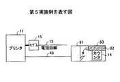
(第5実施例)
図8は、第5実施例を表す。第5実施例では、電気電子装置11はプリンタ、通信回線13は電話回線、測定装置14はカウンタ、送信装置15はモデムである。
【0045】
プリンタ11の電力源は発電装置81である。発電装置81は、発電材料82を収容可能であり、収容する発電材料82を消費して稼動して電力を発生する。
発電材料82を発電装置81に収容させるためには、発電材料83がパックされた発電材料パック82を発電装置81に供給する。プリンタ11は、発電装置81から電力を取得するためのコード43を備え、当該電力を消費して稼動する。
カウンタ14は、例えば発電材料パック83の交換ごとに数値が増加する「加算(UP)カウンタタイプ」のトータルカウンタである。発電装置81は例えば内燃機関、発電材料82は例えばガソリン、発電材料パック83は例えばアルミニウム製のガソリンパックである。
【0046】
ユーザが発電装置81を稼動させると、プリンタ11に電力が供給され、ユーザがプリンタ11のスイッチをオンにすると、プリンタ11は電力を消費して稼動する。発電装置81が収容する発電材料82が切れた際には、ユーザが発電装置81に供給された発電材料パック83を交換する。そして、カウンタ14が、課金パラメータとして発電装置81に供給される発電材料パック83の交換回数をカウントする。さらに、モデム15は、例えば毎月1回、カウンタ14によりカウントされた当月分の「発電装置81に供給される発電材料パック83の交換回数」に係る情報を電話回線13へと送信する。
【0047】
(第6実施例)
図9は、第6実施例を表す。第6実施例では、電気電子装置11はプリンタ、通信回線13は電話回線、測定装置14は発電材料チェッカ、送信装置15はモデムである。
【0048】
プリンタ11の電力源は発電装置81である。発電装置81は、発電材料82を収容可能であり、収容する発電材料82を消費して稼動して電力を発生する。
プリンタ11は、発電装置81から電力を取得するためのコード43を備え、当該電力を消費して稼動する。発電材料チェッカ14は、例えば重量計である。発電装置81は例えば内燃機関、発電材料82は例えばガソリンである。
【0049】
ユーザが発電装置81を稼動させると、プリンタ11に電力が供給され、ユーザがプリンタ11のスイッチをオンにすると、プリンタ11は電力を消費して稼動する。そして、発電材料チェッカ14が、課金パラメータとして発電装置81が収容する発電材料82の残容量をチェックする。さらに、モデム15は、例えば毎月1回、発電材料チェッカ14によりチェックされた当月分の「発電装置81が収容する発電材料82の残容量」に係る情報を電話回線13へと送信する。
【0050】
(第7実施例)
図10は、第7実施例を表す。第7実施例では、電気電子装置11はプリンタ、通信回線13は電話回線、測定装置14はカウンタ、送信装置15はモデムである。
【0051】
プリンタ11の電力源は燃料電池101である。燃料電池101は、燃料102を収容可能であり、収容する燃料102を消費して電力を発生する。プリンタ11は、燃料電池101から電力を取得するためのプラグ62とコード43とを備え、当該電力を消費して稼動する。カウンタ14は、例えば燃料電池101の交換ごとに数値が増加する「加算(UP)カウンタタイプ」のトータルカウンタである。燃料電池101は例えば水素燃料電池であり、この場合の燃料102は圧縮水素となる。
【0052】
ユーザが燃料電池101にプラグ62を挿入すると、プリンタ11に電力が供給され、ユーザがプリンタ11のスイッチをオンにすると、プリンタ11は電力を消費して稼動する。燃料電池101が収容する燃料102が切れた際には、ユーザが燃料電池101を交換する。そして、カウンタ14が、課金パラメータとして燃料電池101の交換回数をカウントする。さらに、モデム15は、例えば毎月1回、カウンタ14によりカウントされた当月分の「燃料電池101の交換回数」に係る情報を電話回線13へと送信する。
【0053】
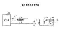
(第8実施例)
図11は、第8実施例を表す。第8実施例では、電気電子装置11はプリンタ、通信回線13は電話回線、測定装置14はカウンタ、送信装置15はモデムである。
【0054】
プリンタ11の電力源は燃料電池101である。燃料電池101は、燃料102を収容可能であり、収容する燃料102を消費して電力を発生する。燃料102を燃料電池101に収容させるためには、燃料102がパックされた燃料パック103を燃料電池101に供給する。プリンタ11は、燃料電池101から電力を取得するためのプラグ62とコード43とを備え、当該電力を消費して稼動する。カウンタ14は、例えば燃料パック103の交換ごとに数値が増加する「加算(UP)カウンタタイプ」のトータルカウンタである。燃料電池101は例えば水素燃料電池であり、この場合の燃料102は水素、燃料パック103は圧縮水素圧縮タンクに格納された水素パックとなる。
【0055】
ユーザが燃料電池101にプラグ62を挿入すると、プリンタ11に電力が供給され、ユーザがプリンタ11のスイッチをオンにすると、プリンタ11は電力を消費して稼動する。燃料電池101が収容する燃料102が切れた際には、ユーザが燃料電池101に供給された燃料パック103を交換する。そして、カウンタ14が、課金パラメータとして燃料電池101に供給される燃料パック103の交換回数をカウントする。さらに、モデム15は、例えば毎月1回、カウンタ14によりカウントされた当月分の「燃料電池101に供給される燃料パック103の交換回数」に係る情報を電話回線13へと送信する。
【0056】
(第9実施例)
図12は、第9実施例を表す。第9実施例では、電気電子装置11はプリンタ、通信回線13は電話回線、測定装置14は燃料チェッカ、送信装置15はモデムである。
【0057】
プリンタ11の電力源は燃料電池101である。燃料電池101は、燃料102を収容可能であり、収容する燃料102を消費して電力を発生する。プリンタ11は、燃料電池101から電力を取得するためのプラグ62とコード43とを備え、当該電力を消費して稼動する。燃料チェッカ14は、例えば重量計である。燃料電池101は例えば水素燃料電池であり、この場合の燃料102は圧縮タンクに格納された圧縮水素となる。
【0058】
ユーザが燃料電池101にプラグ62を挿入すると、プリンタ11に電力が供給され、ユーザがプリンタ11のスイッチをオンにすると、プリンタ11は電力を消費して稼動する。そして、燃料チェッカ14が、課金パラメータとして燃料電池101が収容する燃料102の残容量をチェックする。さらに、モデム15は、例えば毎月1回、燃料チェッカ14によりチェックされた当月分の「燃料電池101が収容する燃料102の残容量」に係る情報を電話回線13へと送信する。
【0059】
(変形例)
なお、図1の課金システムにおいて、課金装置12により実行される課金方法は、本発明に係る課金方法の実施の形態の例である。また、この課金方法をコンピュータに実行させる課金プログラムは、本発明に係る課金プログラムの実施の形態の例である。
【0060】
【発明の効果】
このように、本発明は、課金金額を通信回線を利用して管理する課金システムであって、省エネルギに貢献できて、且つ、電力を消費して稼動する電気電子装置に広く適用できる課金システムを実現することを可能にする。
【図面の簡単な説明】
【図1】本発明に係る課金システムの例を表す。
【図2】算定装置の例を表す。
【図3】メモリマップの例を表す。
【図4】第1実施例を表す。
【図5】第2実施例を表す。
【図6】第3実施例を表す。
【図7】第4実施例を表す。
【図8】第5実施例を表す。
【図9】第6実施例を表す。
【図10】第7実施例を表す。
【図11】第8実施例を表す。
【図12】第9実施例を表す。
【符号の説明】
11 電気電子装置
12 課金装置
13 通信回線
14 測定装置
15 送信装置
16 受信装置
17 算定装置
21 CPU
22 ROM
23 RAM
24 FDD
25 HDD
26 キーボード
27 ディスプレイ
28 システムバス
31 OS
32 基本I/Oプログラム
33 課金金額算定プログラム
34 関連データ
35 ワークエリア
41 家庭用電源
42 コンセント
43 コード
61 バッテリ
62 プラグ
81 発電装置
82 発電材料
83 発電材料パック
101 燃料電池
102 燃料
103 燃料パック[0001]
TECHNICAL FIELD OF THE INVENTION
The present invention relates to an electric / electronic device, a charging device, a charging method, and a charging program.
[0002]
[Prior art]
Copiers, printers, facsimiles and other printing equipment are often traded in leases or rentals. In this case, the billing amount for these printing devices is often calculated based on the number of prints, the number of toner boxes used, and the like. This is a so-called performance charge.
[0003]
It is convenient if the billing amounts for these printing devices are managed using a communication line.
For example, in a billing system described in Japanese Patent Application Laid-Open No. 2001-34446, a billing amount for a printer is calculated based on the number of prints, and a billing amount for the printer is managed using a communication line.
[0004]
[Patent Document 1]
JP-A-2001-34446.
[0005]
[Problems to be solved by the invention]
Now, not only "resource saving" such as paper saving and toner saving but also "energy saving" such as power saving are important concerns. However, in the charging system described in Japanese Patent Application Laid-Open No. 2001-34446, the charging amount of the printer is calculated based on the number of printed sheets, and when the printer is not used, the power of the printer is turned off to save energy. The billing amount of the printer is not particularly low. That is, the billing system does not contribute much to energy saving.
[0006]
Further, the equipment traded in the form of lease or rental is not limited to copying machines, printers, facsimile machines and other printing equipment. However, in the charging system described in Japanese Patent Application Laid-Open No. 2001-34446, the charging amount of the printer is calculated based on the number of printed sheets, and it is difficult or impossible to calculate the charging amount based on the number of printed sheets ( It is difficult or impossible to apply to a device without a printing process.
[0007]
Therefore, the present invention realizes a billing system that manages the billing amount by using a communication line and that can contribute to energy saving and can be widely applied to electric and electronic devices that operate with power consumption. The task is to
[0008]
[Means for Solving the Problems]
The invention (electrical and electronic device) according to claim 1 is an electric and electronic device that operates by consuming electric power, wherein a measuring unit that measures a billing parameter for calculating a billing amount of the electric and electronic device; Transmitting means for transmitting information on the charging parameter measured by the measuring means to a communication line, wherein the charging parameter is a power consumption or a power source connection time of the electric / electronic device.
[0009]
The invention (electrical and electronic device) according to claim 2 is an electric and electronic device that operates by consuming power, wherein a measuring unit that measures a billing parameter for calculating a billing amount of the electric and electronic device, Transmitting means for transmitting information on the charging parameter measured by the measuring means to a communication line, wherein the charging parameter includes a number of times of replacement of a battery which is a power source of the electric / electronic device, a remaining capacity of the battery, a power generation device , The number of times of replacement of the fuel cell, the number of times of replacement of the fuel pack of the fuel cell, or the remaining capacity of the fuel of the fuel cell.
[0010]
According to a third aspect of the present invention, there is provided a billing apparatus that receives, from a communication line, information relating to the billing parameter transmitted by the electric / electronic device according to the first or second aspect, and the receiving means receives the information. Calculating means for calculating a charge for the electric / electronic device based on the information on the charge parameter.
[0011]
According to a fourth aspect of the present invention, there is provided a charging method, wherein the information relating to the charging parameter transmitted by the electric / electronic device according to the first or second aspect is received from a communication line, and the information is received by the receiving step. Calculating a charge amount for the electric / electronic device based on the information on the charge parameter.
[0012]
According to a fifth aspect of the present invention, there is provided a charging program for receiving, from a communication line, information on the charging parameter transmitted by the electric / electronic device according to the first or second aspect, and receiving the information by the receiving step. A calculating step of calculating a billing amount for the electric / electronic device based on the information on the billing parameter.
[0013]
The invention (electrical and electronic device) according to claim 1 or 2 is characterized in that a charging parameter for calculating a charging amount of the electric and electronic device is measured, and information on the charging parameter is transmitted to a communication line. The information related to the charging parameter is received from the communication line, and the charging amount for the electric / electronic device is calculated based on the information related to the charging parameter, and the charging amount for the electric / electronic device is used via the communication line. Can be managed.
[0014]
According to a third aspect of the present invention, there is provided a billing apparatus, a billing method, and a billing program, wherein information on a billing parameter transmitted by the electric / electronic device according to the first or second aspect is transmitted from a communication line. By receiving and calculating the charge amount of the electric / electronic device based on the information on the charge parameter, the charge amount of the electric / electronic device can be managed using the communication line.
[0015]
The “charging parameter” is the power consumption or the power source connection time of the electric / electronic device, or the number of times of replacement of the battery which is the power source of the electric / electronic device, the remaining capacity of the battery, and the power generation material pack of the power generation device. Since it is the number of replacements, the remaining capacity of the power generating material related to the power generation device, the number of replacements of the fuel cell, the number of replacements of the fuel pack related to the fuel cell, or the remaining capacity of the fuel related to the fuel cell, the “charging management” as described above. Can be widely applied to electric and electronic devices that can contribute to energy saving and operate with power consumption.
[0016]
That is, the present invention realizes a billing system that manages the billing amount using a communication line, which can contribute to energy saving and can be widely applied to electric and electronic devices that operate with power consumption. To be able to
[0017]
BEST MODE FOR CARRYING OUT THE INVENTION
An embodiment of the present invention will be described.
[0018]
FIG. 1 shows an example of a billing system according to the present invention. The charging system in FIG. 1 includes an electric /
[0019]
The electric /
[0020]
The
[0021]
Between the electric /
[0022]
The billing parameter is a value measured to calculate the billing amount of the electric /
[0023]
FIG. 2 shows an example of the
[0024]
The
[0025]
FIG. 3 shows an example of a memory map in a state where the charge amount calculation program 33 is loaded from the
[0026]
Here, with respect to the billing system of FIG. 1, an example of a business model of billing management will be described by taking as an example a case where the electric /
[0027]
For example, the OA device is manufactured by a manufacturing company, is wholesaled from the manufacturing company to a sales company, and is leased or rented by a sales company to a user such as a government office, a company, or an educational institution. The calculation standard of the charge amount and the like are determined by the lease contract or the rental contract concluded at this time. The OA device (electrical and electronic device 11) installed in the user's office or the like in this way is connected to the
[0028]
Between the
[0029]
The usage information is exchanged in a predetermined cycle, for example, once a month. The usage information is received from the
[0030]
The employee of the sales company of the
The manufacturing company and the sales company of the
[0031]
The example of the calculating
[0032]
(First embodiment)
FIG. 4 shows a first embodiment. In the first embodiment, the electric /
[0033]
The power source of the copying
[0034]
When the user inserts the
[0035]
(Second embodiment)
FIG. 5 shows a second embodiment. In the second embodiment, the electric /
[0036]
The power source of the copying
[0037]
When the user inserts the
[0038]
(Third embodiment)
FIG. 6 shows a third embodiment. In the third embodiment, the electric /
[0039]
The power source of the
[0040]
When the user inserts the
[0041]
(Fourth embodiment)
FIG. 7 shows a fourth embodiment. In the fourth embodiment, the electric /
[0042]
The power source of the
[0043]
When the user inserts the
[0044]
(Fifth embodiment)
FIG. 8 shows a fifth embodiment. In the fifth embodiment, the electric /
[0045]
The power source of the
In order to store the
The
[0046]
When the user operates the
[0047]
(Sixth embodiment)
FIG. 9 shows a sixth embodiment. In the sixth embodiment, the electric /
[0048]
The power source of the
The
[0049]
When the user operates the
[0050]
(Seventh embodiment)
FIG. 10 shows a seventh embodiment. In the seventh embodiment, the electric /
[0051]
The power source of the
[0052]
When the user inserts the
[0053]
(Eighth embodiment)
FIG. 11 shows an eighth embodiment. In the eighth embodiment, the electric /
[0054]
The power source of the
[0055]
When the user inserts the
[0056]
(Ninth embodiment)
FIG. 12 shows a ninth embodiment. In the ninth embodiment, the electric /
[0057]
The power source of the
[0058]
When the user inserts the
[0059]
(Modification)
In the billing system of FIG. 1, the billing method executed by the
[0060]
【The invention's effect】
As described above, the present invention is a billing system that manages a billing amount using a communication line, and can contribute to energy saving and can be widely applied to electric and electronic devices that operate with power consumption. It is possible to realize.
[Brief description of the drawings]
FIG. 1 shows an example of a billing system according to the present invention.
FIG. 2 shows an example of a calculation device.
FIG. 3 shows an example of a memory map.
FIG. 4 shows a first embodiment.
FIG. 5 shows a second embodiment.
FIG. 6 shows a third embodiment.
FIG. 7 shows a fourth embodiment.
FIG. 8 shows a fifth embodiment.
FIG. 9 shows a sixth embodiment.
FIG. 10 shows a seventh embodiment.
FIG. 11 shows an eighth embodiment.
FIG. 12 shows a ninth embodiment.
[Explanation of symbols]
22 ROM
23 RAM
24 FDD
25 HDD
26
32 Basic I / O program 33 Charge amount calculation program 34 Related data 35
Claims (5)
Translated fromJapanesePriority Applications (1)
| Application Number | Priority Date | Filing Date | Title |
|---|---|---|---|
| JP2002297886AJP2004135084A (en) | 2002-10-10 | 2002-10-10 | Electric / electronic device, charging device, charging method, and charging program |
Applications Claiming Priority (1)
| Application Number | Priority Date | Filing Date | Title |
|---|---|---|---|
| JP2002297886AJP2004135084A (en) | 2002-10-10 | 2002-10-10 | Electric / electronic device, charging device, charging method, and charging program |
Publications (1)
| Publication Number | Publication Date |
|---|---|
| JP2004135084Atrue JP2004135084A (en) | 2004-04-30 |
Family
ID=32287467
Family Applications (1)
| Application Number | Title | Priority Date | Filing Date |
|---|---|---|---|
| JP2002297886APendingJP2004135084A (en) | 2002-10-10 | 2002-10-10 | Electric / electronic device, charging device, charging method, and charging program |
Country Status (1)
| Country | Link |
|---|---|
| JP (1) | JP2004135084A (en) |
Cited By (2)
| Publication number | Priority date | Publication date | Assignee | Title |
|---|---|---|---|---|
| JP2007172220A (en)* | 2005-12-21 | 2007-07-05 | Hewlett-Packard Development Co Lp | Power supply system |
| US8266458B2 (en) | 2008-07-31 | 2012-09-11 | International Business Machines Corporation | Estimating power consumption of a virtual server |
Citations (13)
| Publication number | Priority date | Publication date | Assignee | Title |
|---|---|---|---|---|
| JPH0668912A (en)* | 1992-08-18 | 1994-03-11 | Sony Corp | Battery and battery accounting method |
| JPH0998232A (en)* | 1995-09-29 | 1997-04-08 | Funai Denki Kenkyusho:Kk | Charging device and transmission method for charging data |
| JPH11150809A (en)* | 1997-09-15 | 1999-06-02 | Honda Motor Co Ltd | Battery rental system |
| JP2001057711A (en)* | 1999-01-25 | 2001-02-27 | Zip Charge:Kk | Energy supply system for electric vehicle, battery for electric vehicle, battery charger for the electric vehicle, battery vending apparatus and battery managing system for the electric vehicle |
| JP2001069291A (en)* | 1999-08-30 | 2001-03-16 | Ricoh Co Ltd | Communications system |
| WO2001065627A1 (en)* | 2000-03-01 | 2001-09-07 | Matsushita Electric Industrial Co., Ltd. | Battery and maintenance service system for power supply device |
| JP2002056898A (en)* | 2000-08-09 | 2002-02-22 | Matsushita Electric Ind Co Ltd | Battery Power Unit Replacement Collection System |
| JP2002161997A (en)* | 2000-11-24 | 2002-06-07 | Sony Corp | Hydrogen cartridge, hydrogen gas supply system and hydrogen cartridge administrative method |
| JP2002279272A (en)* | 2001-03-19 | 2002-09-27 | Canon Inc | INFORMATION PROCESSING DEVICE, PRINTING DEVICE, CONSUMER UNIT PURCHASE PROCESSING METHOD, AND STORAGE MEDIUM |
| JP2002304092A (en)* | 2001-04-06 | 2002-10-18 | Canon Inc | Image forming device |
| JP2003076754A (en)* | 2001-09-03 | 2003-03-14 | Sharp Corp | Consumables ordering system, consumables ordering system using the ordering system, communication terminal device, and server device |
| JP2003348245A (en)* | 2002-05-24 | 2003-12-05 | Internet Research Institute Inc | Charging system to function utilized for household electric appliance using information communication network |
| JP2004074530A (en)* | 2002-08-14 | 2004-03-11 | Konica Minolta Holdings Inc | Image formation device and its management system |
- 2002
- 2002-10-10JPJP2002297886Apatent/JP2004135084A/enactivePending
Patent Citations (13)
| Publication number | Priority date | Publication date | Assignee | Title |
|---|---|---|---|---|
| JPH0668912A (en)* | 1992-08-18 | 1994-03-11 | Sony Corp | Battery and battery accounting method |
| JPH0998232A (en)* | 1995-09-29 | 1997-04-08 | Funai Denki Kenkyusho:Kk | Charging device and transmission method for charging data |
| JPH11150809A (en)* | 1997-09-15 | 1999-06-02 | Honda Motor Co Ltd | Battery rental system |
| JP2001057711A (en)* | 1999-01-25 | 2001-02-27 | Zip Charge:Kk | Energy supply system for electric vehicle, battery for electric vehicle, battery charger for the electric vehicle, battery vending apparatus and battery managing system for the electric vehicle |
| JP2001069291A (en)* | 1999-08-30 | 2001-03-16 | Ricoh Co Ltd | Communications system |
| WO2001065627A1 (en)* | 2000-03-01 | 2001-09-07 | Matsushita Electric Industrial Co., Ltd. | Battery and maintenance service system for power supply device |
| JP2002056898A (en)* | 2000-08-09 | 2002-02-22 | Matsushita Electric Ind Co Ltd | Battery Power Unit Replacement Collection System |
| JP2002161997A (en)* | 2000-11-24 | 2002-06-07 | Sony Corp | Hydrogen cartridge, hydrogen gas supply system and hydrogen cartridge administrative method |
| JP2002279272A (en)* | 2001-03-19 | 2002-09-27 | Canon Inc | INFORMATION PROCESSING DEVICE, PRINTING DEVICE, CONSUMER UNIT PURCHASE PROCESSING METHOD, AND STORAGE MEDIUM |
| JP2002304092A (en)* | 2001-04-06 | 2002-10-18 | Canon Inc | Image forming device |
| JP2003076754A (en)* | 2001-09-03 | 2003-03-14 | Sharp Corp | Consumables ordering system, consumables ordering system using the ordering system, communication terminal device, and server device |
| JP2003348245A (en)* | 2002-05-24 | 2003-12-05 | Internet Research Institute Inc | Charging system to function utilized for household electric appliance using information communication network |
| JP2004074530A (en)* | 2002-08-14 | 2004-03-11 | Konica Minolta Holdings Inc | Image formation device and its management system |
Cited By (2)
| Publication number | Priority date | Publication date | Assignee | Title |
|---|---|---|---|---|
| JP2007172220A (en)* | 2005-12-21 | 2007-07-05 | Hewlett-Packard Development Co Lp | Power supply system |
| US8266458B2 (en) | 2008-07-31 | 2012-09-11 | International Business Machines Corporation | Estimating power consumption of a virtual server |
Similar Documents
| Publication | Publication Date | Title |
|---|---|---|
| CN102896918A (en) | Printing control device, printing device, printing control method and printing control system | |
| US20120288288A1 (en) | Image forming apparatus, power supply method, and computer-readable storage medium | |
| CN107735763A (en) | Information processing system, information processor, information processing method and program | |
| CN103425031B (en) | The method of the developing cell of imaging device and control imaging device | |
| CN104903111B (en) | Network printer system | |
| CN103873720A (en) | Job processing apparatus and method of controlling the same | |
| JP2004135084A (en) | Electric / electronic device, charging device, charging method, and charging program | |
| JP4585363B2 (en) | Billing management apparatus, billing management method, billing management program | |
| Ciechanowicz et al. | Towards a business case for vehicle-to-grid—Maximizing profits in ancillary service markets | |
| CN102582291B (en) | For controlling information processor and the information processing method of power consumption | |
| JP2003335026A (en) | Image forming system, power information management method, program, and storage medium | |
| CN110633918A (en) | Energy storage system operation evaluation determination method, device, equipment and storage medium | |
| JPWO2020153481A1 (en) | Storage device and storage method | |
| JP2020043416A (en) | Apparatus management system and apparatus management method | |
| JP7216816B2 (en) | Stored power derived management device, method, and program | |
| JP2019031023A (en) | Image formation apparatus, control method, and program | |
| US7587371B2 (en) | Charging method and imaging apparatus for equitable and simple charging | |
| US8040543B2 (en) | Instruction file execution device, instruction file execution method and job flow system | |
| CN102195834B (en) | Information processing device, network system, and power-saving control method | |
| JP2010005809A (en) | Image forming apparatus and program | |
| JP4531308B2 (en) | Billing system for image forming fee according to toner amount and image forming system | |
| JP4270762B2 (en) | Self-supplied power supply delivery method and power generation facility | |
| JP5867895B2 (en) | Billing management system | |
| JP2010182112A (en) | Charging system, charging apparatus, and charging program | |
| JP2008052630A (en) | Billing system and collation program |
Legal Events
| Date | Code | Title | Description |
|---|---|---|---|
| A621 | Written request for application examination | Free format text:JAPANESE INTERMEDIATE CODE: A621 Effective date:20050308 | |
| A977 | Report on retrieval | Free format text:JAPANESE INTERMEDIATE CODE: A971007 Effective date:20061023 | |
| A131 | Notification of reasons for refusal | Free format text:JAPANESE INTERMEDIATE CODE: A131 Effective date:20061114 | |
| A521 | Written amendment | Free format text:JAPANESE INTERMEDIATE CODE: A523 Effective date:20070115 | |
| A131 | Notification of reasons for refusal | Free format text:JAPANESE INTERMEDIATE CODE: A131 Effective date:20070320 | |
| A02 | Decision of refusal | Free format text:JAPANESE INTERMEDIATE CODE: A02 Effective date:20070807 |