JP2004130120A - Housing type syringe with closed body - Google Patents
Housing type syringe with closed bodyDownload PDFInfo
- Publication number
- JP2004130120A JP2004130120AJP2003313021AJP2003313021AJP2004130120AJP 2004130120 AJP2004130120 AJP 2004130120AJP 2003313021 AJP2003313021 AJP 2003313021AJP 2003313021 AJP2003313021 AJP 2003313021AJP 2004130120 AJP2004130120 AJP 2004130120A
- Authority
- JP
- Japan
- Prior art keywords
- needle holder
- injection needle
- syringe
- piston
- shaft
- Prior art date
- Legal status (The legal status is an assumption and is not a legal conclusion. Google has not performed a legal analysis and makes no representation as to the accuracy of the status listed.)
- Pending
Links
- 238000002347injectionMethods0.000claimsabstractdescription199
- 239000007924injectionSubstances0.000claimsabstractdescription199
- 239000007788liquidSubstances0.000claimsdescription46
- 238000003860storageMethods0.000claimsdescription20
- 230000033001locomotionEffects0.000claimsdescription13
- 238000007789sealingMethods0.000claimsdescription9
- 238000003780insertionMethods0.000claimsdescription7
- 230000037431insertionEffects0.000claimsdescription7
- 239000002131composite materialSubstances0.000claims6
- 238000005303weighingMethods0.000claims2
- 239000000243solutionSubstances0.000abstractdescription2
- 210000003811fingerAnatomy0.000description27
- 230000007246mechanismEffects0.000description14
- 230000002093peripheral effectEffects0.000description10
- 239000000463materialSubstances0.000description7
- 238000000034methodMethods0.000description6
- 238000004519manufacturing processMethods0.000description5
- 239000004033plasticSubstances0.000description5
- 210000003813thumbAnatomy0.000description5
- 230000008569processEffects0.000description4
- 238000005452bendingMethods0.000description3
- 230000008901benefitEffects0.000description3
- 230000004048modificationEffects0.000description3
- 238000012986modificationMethods0.000description3
- 238000003825pressingMethods0.000description3
- 230000009471actionEffects0.000description2
- 239000004020conductorSubstances0.000description2
- 239000012530fluidSubstances0.000description2
- 230000001105regulatory effectEffects0.000description2
- 239000007787solidSubstances0.000description2
- 208000030507AIDSDiseases0.000description1
- 208000035473Communicable diseaseDiseases0.000description1
- 239000004743PolypropyleneSubstances0.000description1
- 230000004308accommodationEffects0.000description1
- 230000000903blocking effectEffects0.000description1
- 238000010276constructionMethods0.000description1
- 230000006378damageEffects0.000description1
- 230000026058directional locomotionEffects0.000description1
- 239000003814drugSubstances0.000description1
- 230000000694effectsEffects0.000description1
- 208000006454hepatitisDiseases0.000description1
- 231100000283hepatitisToxicity0.000description1
- -1polypropylenePolymers0.000description1
- 229920001155polypropylenePolymers0.000description1
- 230000000717retained effectEffects0.000description1
- 210000004935right thumbAnatomy0.000description1
- 239000003566sealing materialSubstances0.000description1
- 230000000087stabilizing effectEffects0.000description1
Images


Classifications
- A—HUMAN NECESSITIES
- A61—MEDICAL OR VETERINARY SCIENCE; HYGIENE
- A61M—DEVICES FOR INTRODUCING MEDIA INTO, OR ONTO, THE BODY; DEVICES FOR TRANSDUCING BODY MEDIA OR FOR TAKING MEDIA FROM THE BODY; DEVICES FOR PRODUCING OR ENDING SLEEP OR STUPOR
- A61M5/00—Devices for bringing media into the body in a subcutaneous, intra-vascular or intramuscular way; Accessories therefor, e.g. filling or cleaning devices, arm-rests
- A61M5/178—Syringes
- A61M5/31—Details
- A61M5/32—Needles; Details of needles pertaining to their connection with syringe or hub; Accessories for bringing the needle into, or holding the needle on, the body; Devices for protection of needles
- A61M5/3205—Apparatus for removing or disposing of used needles or syringes, e.g. containers; Means for protection against accidental injuries from used needles
- A61M5/321—Means for protection against accidental injuries by used needles
- A61M5/3243—Means for protection against accidental injuries by used needles being axially-extensible, e.g. protective sleeves coaxially slidable on the syringe barrel
- A—HUMAN NECESSITIES
- A61—MEDICAL OR VETERINARY SCIENCE; HYGIENE
- A61M—DEVICES FOR INTRODUCING MEDIA INTO, OR ONTO, THE BODY; DEVICES FOR TRANSDUCING BODY MEDIA OR FOR TAKING MEDIA FROM THE BODY; DEVICES FOR PRODUCING OR ENDING SLEEP OR STUPOR
- A61M5/00—Devices for bringing media into the body in a subcutaneous, intra-vascular or intramuscular way; Accessories therefor, e.g. filling or cleaning devices, arm-rests
- A61M5/178—Syringes
- A61M5/31—Details
- A61M5/32—Needles; Details of needles pertaining to their connection with syringe or hub; Accessories for bringing the needle into, or holding the needle on, the body; Devices for protection of needles
- A61M5/3205—Apparatus for removing or disposing of used needles or syringes, e.g. containers; Means for protection against accidental injuries from used needles
- A61M5/321—Means for protection against accidental injuries by used needles
- A61M5/322—Retractable needles, i.e. disconnected from and withdrawn into the syringe barrel by the piston
- A—HUMAN NECESSITIES
- A61—MEDICAL OR VETERINARY SCIENCE; HYGIENE
- A61M—DEVICES FOR INTRODUCING MEDIA INTO, OR ONTO, THE BODY; DEVICES FOR TRANSDUCING BODY MEDIA OR FOR TAKING MEDIA FROM THE BODY; DEVICES FOR PRODUCING OR ENDING SLEEP OR STUPOR
- A61M5/00—Devices for bringing media into the body in a subcutaneous, intra-vascular or intramuscular way; Accessories therefor, e.g. filling or cleaning devices, arm-rests
- A61M5/178—Syringes
- A61M5/31—Details
- A61M5/32—Needles; Details of needles pertaining to their connection with syringe or hub; Accessories for bringing the needle into, or holding the needle on, the body; Devices for protection of needles
- A61M5/34—Constructions for connecting the needle, e.g. to syringe nozzle or needle hub
- A61M5/344—Constructions for connecting the needle, e.g. to syringe nozzle or needle hub using additional parts, e.g. clamping rings or collets
- A—HUMAN NECESSITIES
- A61—MEDICAL OR VETERINARY SCIENCE; HYGIENE
- A61M—DEVICES FOR INTRODUCING MEDIA INTO, OR ONTO, THE BODY; DEVICES FOR TRANSDUCING BODY MEDIA OR FOR TAKING MEDIA FROM THE BODY; DEVICES FOR PRODUCING OR ENDING SLEEP OR STUPOR
- A61M5/00—Devices for bringing media into the body in a subcutaneous, intra-vascular or intramuscular way; Accessories therefor, e.g. filling or cleaning devices, arm-rests
- A61M5/178—Syringes
- A61M5/31—Details
- A61M2005/3103—Leak prevention means for distal end of syringes, i.e. syringe end for mounting a needle
- A61M2005/3106—Plugs for syringes without needle
- A—HUMAN NECESSITIES
- A61—MEDICAL OR VETERINARY SCIENCE; HYGIENE
- A61M—DEVICES FOR INTRODUCING MEDIA INTO, OR ONTO, THE BODY; DEVICES FOR TRANSDUCING BODY MEDIA OR FOR TAKING MEDIA FROM THE BODY; DEVICES FOR PRODUCING OR ENDING SLEEP OR STUPOR
- A61M5/00—Devices for bringing media into the body in a subcutaneous, intra-vascular or intramuscular way; Accessories therefor, e.g. filling or cleaning devices, arm-rests
- A61M5/178—Syringes
- A61M5/31—Details
- A61M5/32—Needles; Details of needles pertaining to their connection with syringe or hub; Accessories for bringing the needle into, or holding the needle on, the body; Devices for protection of needles
- A61M5/3205—Apparatus for removing or disposing of used needles or syringes, e.g. containers; Means for protection against accidental injuries from used needles
- A61M2005/3206—Needle or needle hub disconnecting devices forming part of or being attached to the hub or syringe body
- A—HUMAN NECESSITIES
- A61—MEDICAL OR VETERINARY SCIENCE; HYGIENE
- A61M—DEVICES FOR INTRODUCING MEDIA INTO, OR ONTO, THE BODY; DEVICES FOR TRANSDUCING BODY MEDIA OR FOR TAKING MEDIA FROM THE BODY; DEVICES FOR PRODUCING OR ENDING SLEEP OR STUPOR
- A61M5/00—Devices for bringing media into the body in a subcutaneous, intra-vascular or intramuscular way; Accessories therefor, e.g. filling or cleaning devices, arm-rests
- A61M5/178—Syringes
- A61M5/31—Details
- A61M5/32—Needles; Details of needles pertaining to their connection with syringe or hub; Accessories for bringing the needle into, or holding the needle on, the body; Devices for protection of needles
- A61M5/3205—Apparatus for removing or disposing of used needles or syringes, e.g. containers; Means for protection against accidental injuries from used needles
- A61M5/321—Means for protection against accidental injuries by used needles
- A61M5/322—Retractable needles, i.e. disconnected from and withdrawn into the syringe barrel by the piston
- A61M5/3221—Constructional features thereof, e.g. to improve manipulation or functioning
- A61M2005/3231—Proximal end of needle captured or embedded inside piston head, e.g. by friction or hooks
Landscapes
- Health & Medical Sciences (AREA)
- Engineering & Computer Science (AREA)
- Heart & Thoracic Surgery (AREA)
- Vascular Medicine (AREA)
- Anesthesiology (AREA)
- Biomedical Technology (AREA)
- Hematology (AREA)
- Life Sciences & Earth Sciences (AREA)
- Animal Behavior & Ethology (AREA)
- General Health & Medical Sciences (AREA)
- Public Health (AREA)
- Veterinary Medicine (AREA)
- Environmental & Geological Engineering (AREA)
- Infusion, Injection, And Reservoir Apparatuses (AREA)
Abstract
Description
Translated fromJapanese本発明は、医療分野などで使用される格納型注射器に関する。The present invention relates to a retractable syringe used in the medical field and the like.
今日、注射器を使用することによる医者や看護婦に及ぶ危険性が大きく認識されるようになってきている。すなわち、連続して使用する者を除いて、エイズや肝炎等の伝染性の病気が注射器の再使用により悲惨な状況をもたらしてきたからである。しかしながら、このような危険性やその他の問題にもかかわらず、これまで多年にわたり販売されてきた通常の注射器がいまだに大量に使用され、その状態は依然として変化していない。このような注射器には取り外し可能なさやを使用できるが、使用した皮下注射用の針をこのさやに戻そうとするような場合に、しばしば、不用意に針にささるような事態が起こることを効果的に防止する対策に欠けている。また、このようなさやは皮下注射用の針の危険かつ有害な再使用を防止する上での対策にも欠けているといえる。Today, the dangers of using syringes to doctors and nurses are becoming increasingly recognized. That is, infectious diseases such as AIDS and hepatitis have caused disastrous situations due to reuse of syringes, except for those who use the syringes continuously. However, despite these dangers and other problems, conventional syringes, which have been sold for many years, are still used in large quantities and their condition remains unchanged. Detachable pods can be used with such syringes, but if you try to put the used hypodermic needle back into this pod, you will often inadvertently get into the needle. Lack of measures to effectively prevent Such pods also lack measures to prevent dangerous and harmful reuse of hypodermic needles.
注射器の胴体に注射針もしくは注射針ホルダを格納し得る注射器の構成として、注射針を胴体に格納できる米国特許第4838870号および4650468号、あるいは、注射針ホルダを胴体に格納する米国特許第4747830号および4790822号が挙げられる。なお、後者の米国特許第4747830号および4790822号はプランジャシャフト端部の破断および注射針とホルダとの胴体中における保持について付加的に開示するものである。US Pat. Nos. 4,838,870 and 4,650,468, in which a syringe needle can be stored in the body, or U.S. Pat. No. 4,478,830, in which a syringe holder can be stored in the body, can be stored in the body of the syringe. And 4790822. The latter U.S. Pat. Nos. 4,478,830 and 4,790,822 additionally disclose the breaking of the end of the plunger shaft and the holding of the injection needle and the holder in the body.
注射針若しくは注射針のハウジングを注射器の胴体中に収納することは理論的に有利である。It is theoretically advantageous to house the injection needle or the housing of the injection needle in the barrel of the syringe.
しかしながら、実際には、上述の特許に開示された構成はその作用面において実用的でなく、製造する上でコスト高であり、注射針や注射針ホルダの格納した後に注射器の胴体中に必要量の流体を収容する余地を残すという点で問題がある。さらに、これらの新しい構成は従来の通常の注射器に比してその動作が大きくことなるために、その使用の妥当性を訴えるには安全性の確保の点でまだ不十分であった。However, in practice, the configuration disclosed in the above-mentioned patent is not practical in terms of its operation and is costly to manufacture, and after storing the injection needle or the needle holder, the necessary amount is stored in the body of the syringe. There is a problem in that it leaves room for containing the fluid. In addition, these new configurations have a greater operation than conventional conventional syringes, and are still insufficient in security to justify their use.
すなわち、これら特許に開示される注射針を胴体に引き込む構成は非常に複雑な機構を有しているために、製造コストがかさみ、操作面で実用性に欠ける。加えて、注射針をつかんで胴体中に格納するための機構はかなりかさばるために、注射器により十分量の流体を注射することが困難である。すなわち、このような格納により、胴体中の必要量の液体が後に漏れ出すことになる。たとえ、この液体が胴体中に保持されるとしても、処分等の望ましからぬ状況下において胴体から流出することもある。要するに、注射器は極めて単純な装置であり、その構成及び動作が簡単で安価に製造できることが必要とされる。さもなければ、毎年大量に使用される注射器の広範な需要に適さないからである。That is, the structure for retracting the injection needle disclosed in these patents into the body has a very complicated mechanism, so that the manufacturing cost is increased and the operation is not practical. In addition, the mechanism for grasping the needle and storing it in the torso is quite bulky, making it difficult to inject a sufficient amount of fluid with a syringe. That is, such storage causes the required amount of liquid in the body to later leak. Even if this liquid is retained in the fuselage, it may flow out of the fuselage under undesirable conditions such as disposal. In short, a syringe is a very simple device, and its configuration and operation must be simple and inexpensive to manufacture. Otherwise, it would not meet the widespread demand for syringes used in large quantities each year.
上述した胴体中に注射針若しくは注射針ホルダ全体を格納する方法を開示した特許は、格納を行う機構が複雑であるとともに、製造コストがかさみ、操作面での失敗を引き起こし易い。これらの機構においては、胴体の前端部が壊れ易い構成であることを要するものがある。しかしながら、このような構成の胴体は必ずしも妥当なコストで製造できるとは言えず、また、容易に破壊できるとは限らない。さらに、このような壊れ易い部分によって、胴体の極めて重要な部分の構造が弱くなり、破壊後には胴体の封止ができなくなるという問題があった。また、上述の機構においては、プランジャシャフトを壊して胴体を作動不能とし、注射針やホルダが胴体の前端部から外部に押し戻されないようにすることを要するものがある。しかしながら、このような機構においてプランジャシャフトを破壊することは実用的に困難である。たとえ前記シャフトを破壊することが可能でも、このような行為をすることは注射器の使用者にとって気のすすまないことである。つまり、使用者は固定されていない注射針や注射針ホルダが胴体から飛び出したり、このような皮下注射針が偶然にささるという事態を当然に予想するからである。さらに、このような胴体中に注射針やホルダを格納する機構においては、格納の後に、胴体がその一端において開放状態となる。したがって、内部の液体が外気にふれて汚染されるおそれがある。このことからも、胴体中に注射針やホルダを格納するこれら二つの機構は注射器の構成を複雑かつコスト高にしており、その価格および複雑さは将来における使用の実現をおよそ予想させない程度である。特許 The above-mentioned patent that discloses a method for storing the injection needle or the entire injection needle holder in the body has a complicated mechanism for storing the needle, increases the manufacturing cost, and easily causes a failure on the operation surface. Some of these mechanisms require that the front end of the body be fragile. However, a fuselage of such a configuration cannot always be said to be able to be manufactured at a reasonable cost, and is not always easily breakable. Further, such a fragile portion weakens the structure of a very important part of the fuselage, so that there is a problem that the fuselage cannot be sealed after the fracture. Some of the above mechanisms require that the plunger shaft be broken to render the body inoperable so that the injection needle or holder is not pushed back out of the front end of the body. However, it is practically difficult to break the plunger shaft in such a mechanism. Even though it is possible to break the shaft, performing such an action would be awkward to the syringe user. That is, the user naturally expects a situation in which an unfixed injection needle or injection needle holder jumps out of the body or such a hypodermic injection needle accidentally comes into contact. Further, in such a mechanism for storing the injection needle and the holder in the body, the body is opened at one end after storage. Therefore, the liquid inside may be contaminated by touching the outside air. This also suggests that these two mechanisms for storing the needle and holder in the torso add complexity and cost to the configuration of the syringe, and its price and complexity are such that future use is unlikely. .
それゆえ、注射針や注射針ホルダを容易かつ迅速に積極的に注射器の胴体中に封止状態で格納できる新規の改良された注射器の実現が要求されており、このような注射器は、ピストンからシャフトを容易に破壊して除いて注射器をその後において使用不可とし、前記注射器の開放した前端部を封止して注射針やホルダが不用意に前記前端部から飛び出さないようにする単純かつ容易な手段を供与する手段を有しており、比較的安価に製造でき、操作が単純で分かり易く、すなわち、使用において安全かつ容易であり、胴体からの最大量の液体の注射が可能であり、前記注射ホルダが胴体中に不用意に引き込まれることを防止し、格納された注射針を前記胴体中に保持し、前記胴体中の注射針および液体を封止し、さらに、封止状態で処分できる。Therefore, there is a need for a new and improved syringe that can easily and quickly positively and positively store a needle or needle holder in a sealed manner in the body of the syringe, and such a syringe must be displaced from the piston. Simple and easy to easily break the shaft to remove the syringe afterwards and seal the open front end of the syringe to prevent the needle or holder from accidentally popping out of the front end It is relatively inexpensive to manufacture, simple and intuitive to operate, i.e. safe and easy to use, capable of injecting the largest amount of liquid from the fuselage, Prevents the injection holder from being accidentally pulled into the body, holds the stored injection needle in the body, seals the injection needle and liquid in the body, and further disposes in a sealed state so That.
本発明は格納型注射器を提供するものであり、この注射器においては、注射針ホルダが移動可能に配置されかつその前端部において固定され、ピストンおよびシャフトが前記注射器におけるプランジャとして作用して通常の方法により液体を引き込みかつ投与する。このような注射器を使用して液体を投与する場合は、ピストンを注射針ホルダに通常の方法で係合させるに要する力よりも僅かに大きな力で前記プランジャが押し込まれる。前記プランジャはその後ピストンとこれに連結した注射針ホルダを引っ張ることにより引き戻され、胴体の前端で移動可能に結合した開放端部から離れる。その後、前記ピストンと注射針の係合体は胴体の後方開放部の近傍に格納され、同所において上記シャフトの脆弱化部分がピストンの近傍において迅速容易に破壊される。而して、ピストンはその位置を保持しながら前記胴体の後方開放部を封止し、かつ、前記注射針ホルダが前記胴体の後方端部から外方に移動することを規制する。なお、シャフトの自由端部はその後胴体の前端開放部に挿入され、前記シャフトに取り付けた封止手段が胴体の前端開放部に位置して、胴体を封止するとともに、シャフトを注射針ホルダの胴体中における移動を抑止する位置に係止する。The present invention provides a retractable syringe in which a needle holder is movably arranged and fixed at its front end, with a piston and shaft acting as a plunger in said syringe in a conventional manner. To draw and dispense the liquid. When dispensing liquid using such a syringe, the plunger is pushed in with a force slightly greater than the force required to engage the piston with the needle holder in the usual manner. The plunger is then withdrawn by pulling on the piston and the needle holder connected thereto, leaving the movably connected open end at the front end of the body. Thereafter, the engagement body between the piston and the injection needle is retracted near the rear opening of the body, where the weakened portion of the shaft is quickly and easily broken near the piston. Thus, the piston seals the rear opening of the body while maintaining its position, and restricts the needle holder from moving outward from the rear end of the body. The free end of the shaft is then inserted into the front end opening of the body, and the sealing means attached to the shaft is located at the front end opening of the body, sealing the body and connecting the shaft to the needle holder. It is locked at a position in the torso that inhibits movement.
これらすべての操作は単純かつ分かり易い機構を用いて簡単容易に行うことができ、しかも、この種の注射器の構造における被破壊構成要素について本質的に困難であった主たる破壊機構を必要としていない。すなわち、本発明の注射器における主眼点は胴体部の一端におけるピストンによる係止および封止機構、同胴体部の他端部におけるシャフトによる係止および封止機構、ならびに、胴体中におけるシャフトの注射針若しくは注射針ホルダへの突接機構および注射針の保持機構である。なお、全体のパッケージは安全かつ容易な方法により処分することができる。All of these operations can be easily and easily performed using a simple and intuitive mechanism, and do not require a main destruction mechanism that was inherently difficult for the components to be destroyed in this type of syringe construction. That is, the main point of the syringe of the present invention is a locking and sealing mechanism by a piston at one end of the body, a locking and sealing mechanism by a shaft at the other end of the body, and an injection needle for the shaft in the body. Alternatively, a mechanism for projecting and contacting the injection needle holder and a mechanism for holding the injection needle. Note that the entire package can be disposed of in a safe and easy way.
さらに、前記注射器は使用後においてその注射針の端部を被覆するさやを使用する必要がなく、同注射器や注射針の再使用を防止し、さらに、同注射器内に既に存していた注射器針や液体が使用済みの注射器の処分地において放出され拡散することを規制する。Further, the syringe does not require the use of a sheath covering the end of the needle after use, thereby preventing reuse of the syringe and the needle, and further, the syringe needle already existing in the syringe. And dispersal of liquids and liquids at the disposal site of used syringes.
したがって、本発明の目的は従来の他の格納型注射器の欠点を解消する新規の改良された格納型注射器を提供することである。Accordingly, it is an object of the present invention to provide a new and improved retractable syringe that overcomes the shortcomings of other conventional retractable syringes.
本発明の密閉胴体を有する格納型注射器によれば、注射針や注射針ホルダを容易かつ迅速に積極的に注射器の胴体中に封止状態で格納することができる。According to the retractable syringe having the closed body of the present invention, the injection needle and the needle holder can be easily and promptly positively stored in the body of the syringe in a sealed state.
本発明の他の目的および利点は以下の詳細な説明および図面を参照することにより一層明らかとなる。なお、図面における同一図形は同一部分を示す。Other objects and advantages of the present invention will become more apparent by referring to the following detailed description and drawings. The same figure in the drawings indicates the same part.
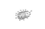
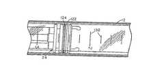
第1図は中空の注射器胴体部12を有する格納型注射器10を示す。この胴体部および注射器における他の適当な部分はポリプロピレン等のプラスチック材料により形成されている。前記注射器胴体部12は前端部15と後端開口部17とを有する。また、注射針ホルダ18がこの前端部に移動可能に配置されている。一方、移動可能のプランジャがシャフト14と連結しているO−リングシールを備えるピストン24を有しており、前記シャフトは胴体部12の開口端部17から外方に延出している。前記ピストン24は、シャフト14の端部において親指により駆動される作動面16と胴体部の開口端部17に存するフィンガーグリップ26との共同作用により、注射器の作動において、押し出されたり引き戻されたりする。前記ピストン24は後に詳述する注射針ホルダ18の端部32を把持する手段を備えており、前記注射針ホルダを後方に引いて、注射針ホルダ18、注射針ハウジング20および注射針22のすべてを第11図に示すごとく胴体部内に格納された状態にする。注射針ホルダがこの位置にあるとき、注射針22は完全に胴体部12の内部に封入されている。その後、シャフト14がピストン24から破断され、前記シャフト14の破壊された自由端部が導体部12の前端開口部15より挿入される。このようにして、導体部の前端開口部が前記シャフトにより封止られ、胴体部の後端開口部がピストンにより封止られて、注射針の胴体部内に封入して格納された状態が確保される。すなわち、胴体部の各端部がピストンとシャフトによりそれぞれ封止されるので、注射針や残存する液体が前記胴体部中に封じ込められる。これにより、胴体部の廃棄処分の準備が整う。FIG. 1 shows a retractable syringe 10 having a
なお、他の実施態様においては、ピストンおよびこれに連結した注射針ホルダを胴体部中に係止可能にしてもよく、あるいは、胴体部の後端開口部から引き出せないようにすることも可能である。また、分離型「C」クリップ係止手段が注射針を、注射器の使用者が移動するまで、移動可能な連結部から異動しないようにしている。さらに、胴体部と注射針ホルダとの間の間隙は「O」リングシールにより封じられている。In another embodiment, the piston and the injection needle holder connected to the piston may be locked in the body, or may not be pulled out from the rear end opening of the body. is there. A separate "C" clip locking means keeps the injection needle from moving from the movable connection until the user of the syringe moves. Further, the gap between the body and the needle holder is sealed by an "O" ring seal.
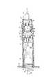
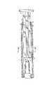
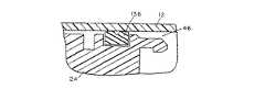
また、さらに他の実施態様においては、第31図および32図に示すごとく、注射針ホルダ152の後端部が上記の把持手段、すなわち指部148および150、を備えている。この場合、ピストン142の前端部近傍には外周スロット144を備える突出部が設けられている。而して、前記指部はピストン142の端部を把持し、前記ピストンと注射針ホルダとを一体に係止する。その後、プランジャがピストン142とこれに固定された注射針ホルダ152とを注射器の開口端部から前述のごとき格納位置まで後方に引く。In still another embodiment, as shown in FIGS. 31 and 32, the rear end portion of the
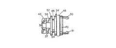
次に、第1図、5図、6図および9図において、ピストン24はO−リング48を保持する外周溝49を備えている。前記O−リング48は適当な材料であれば何でもよく、前記ピストンと胴体部12の内面との間における移動可能なシール材として機能する。ただし、前記O−リングは好ましくはゴムから成る。つまり、ゴム材はプラスチック製胴体部に対して、プラスチック対プラスチックの場合よりも良好なシール材として機能することが知られているからである。なお、前記溝49は十分な幅と深さを備えており、O−リング48が前記溝からはずれないようになっている。また、O−リング48は胴体部の内面を拭くワイパーとして機能し、これに伴って、液体がピストンの動作により当中空の注射器胴体部12の中にあるいは外に移動する。さらに、ピストン24は幅中心の凹部56を備えており、この凹部は、この注射器の一実施例において、後に詳述する第14図、15図および16図に示すようにナットタイプ整合部94を受け入れてこれと共同作用する。前記ピストン24の前端には一対の弓形部材30および31が備えられており、その各々が内側ショルダー部33を備える指部を形成している。さらに、前記ショルダー部は互いに共同して注射針ホルダ18の後端部上の後端カム面27を摺動する。第3図に示すごとく、これらの指部30および31は十分な弾性力を有しており、カム面21に沿って変形して外側から注射針ホルダ18の溝32に嵌合するようになっている。しかしながら、これらの指部30および31は弓形の部分のみであり、後に詳細に述べる理由によって、溝32の全外周を覆うことはない。Next, in FIGS. 1, 5, 6 and 9, the
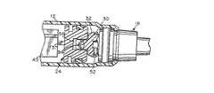
また、ピストンは一対のリム57および59の間に外周スロット65を備えており、その外径は胴体部の内径よりも若干小さく設定されている。また、これらのリム57および59はピストン動作に対して長手方向における安定性を与え、後述する他の機能をも供与する。さらに、ピストン24は、第4図および第5図に示すごとく、ピストンシャフト14に一対の半径方向に離間する脆弱化部位37および38を介して連結されている。一方、これらの脆弱化部位は複数の内部接続した薄型部材に接続しており、前記部材は胴体部の内面に対応した長方形状に形成されている。また、このような組合せ式の内部接続薄型部材は第2図に示すごとく周面におよぶ断面領域を形成し、各部材はその長手方向の端部に沿って互いに連結している。すなわち、薄型部材90は薄型部材86の側縁に連結しており、この部材86は薄型部材88に連結しており、この部材88は薄型部材87に連結しており、さらに、この部材87は側方に突出する薄型部材89を有している。すなわち、このような組合せシャフトの構造40により、ピストン24の移動の際の折り曲げ力に対して横方向の剛性が与えられることが理解できる。また、このような形状にすることにより、第12図に示すごとく胴体部の開口端部に前記シャフト24が挿入された時に、胴体部12の内部に注射針の端部や注射針ハウジング20を収容し得る空間が与えられる。さらに、カラーまたはディスク34および42がシャフト14にモールド形成されており、外方に延出して第1図および2図に示すごとく胴体部12内のシャフトの中心位置を決めている。The piston has an outer
第1図、4図、5図および6図に戻って、上述の薄型部材37および38から成る脆弱化部位は半径方向に配され、比較的小さな断面形状を有する。これらの薄型部材は任意の方向に横方向の折り曲げ力が加えられた時に破壊することができる。ただし、シャフト14における第2図により前述した他の断面形状はこのような横方向の折り曲げ力に耐えることができる。これらの薄型部材37および38はさらにその片面または両面に各々刻みが入れられて、これらの脆弱化部位をさらに破壊しやすくしている。また、この脆弱化部位はシャフトの残部をピストン24の後端面に内部接続しているため、シャフトはピストンの近傍位置で破壊することができる。、 4 Returning to FIGS. 1, 4, 5, and 6, the weakened portion composed of the
なお、他の実施態様においては、第26図、27図および28図に示すごとく、主に横方向の安定性を付加するために、変形した脆弱化部位が当薄型部材37および38の代わりに使用されている。この実施態様においては、薄型部材37および38にそれぞれ対応する薄型部材138および140が断面「L」形状に形成されている。各部位に対応する「L」形状の底部は隣接する薄型部材86および87と一体になっている。さらに、各「L」字形部材は139および141における外端部151を除くすべての面に刻みが入れられて前述したようなシャフトの破壊を容易にしている。In another embodiment, as shown in FIGS. 26, 27 and 28, the deformed weakened portion is replaced with the
また、胴体部12の後端開口部17はV字形内面37を有しており、この内面は前記開口部の内径を狭めている。さらに、それぞれのカラー34および42はリング表面36の内径よりも小さい外径を有しており、それゆえ自由にこれを通過することができる。しかしながら、ピストン24がより大きな直径のリム57および59を有しているので、これらがピストンをV−字形リング面36を通って開口端部17から外出することを規制している。一実施態様においては、第9図および10図に示すごとく、リム57の直径がリング面36の内径よりもやや大きく、また、リム57が斜めの外端面を備えているので、リム57はV−字形リング36に大してカム状に接触することができる。而して、前記内側V−字形突出部36はスロット65に嵌合する。一方、ピストンリム59の形状は比較的方形状であり、V−字形突出部36の側面に接し、開口部17における通過を防止する。このことはピストンを胴体部12の後端開口部17に対して有効に係止する。The rear end opening 17 of the
したがって、端部16を介する引っ張り力がプランジャを引くと、シャフト14が開口端部17を通過して、ピストンが引き戻される。その後、末端リム57がV−字形突出部36の側面に接触する。そして、さらに力をわずかに加えると、リム57はその斜めの面をV−字形リング36の内面にカム状に接しながら開口部17を通過して引き戻される。このことによって、V−字形リングは前述したように固定され、ピストン24が開口部36において係止され保持される。なお、スロット65の外端部が備えるリング面36の側面に対する弾性力は液体が開口端部17から流出しない程度のシール制を有する。さらに、O−リング48も液体が開口端部17を通過して胴体部12から流出することを防ぐ機能を有する。Therefore, when the pulling force through the
すなわち、ピストン24は胴体部の開口端部17における規制ネック部36を介してピストンを押し込むことにより胴体部12中に初期的に挿入される。この操作はシャフト24を介してピストンに相当な力を長手方向に沿って加えることにより実行できる。つまり、この力はピストンとその外部リム57および59とをネック部36に通過させるに十分なものである。ただし、ネック部36は、スロット65に嵌合すると、ピストンを基本的に係止して固定しかつ封止された状態にするため、ピストンは注射器の通常の操作においてピストンに加えられる通常の力では保持されたままの状態となる。また、このような係止状態からピストンを移動するに要する力、例えば、その初期的挿入時においてネック部39を通過してピストンを挿入するに要する力は、注射器の通常の操作では発生しえないものである。That is, the
なお、第19図および20図に示すごとき他の実施態様においては、ピストンは異なる形状のリム部材92を備えており、前記部材は斜めの端面を有しておらず、また、リム59の外径に概ね相当する外径を備えている。したがって、ピストンの後方移動においては、リム92の外端面がリング36の面に接して、ピストンのリング92がリング状突出部36を抜けて開口端部17から出るのを付勢でいる。したがって、この実施態様においては、リング状突出部36はスロット65に嵌合することはなく、ピストンは胴体部の後端開口部に係止されない。むしろ、ピストンは胴体部の開口端部に引き込まれて、その位置で保持される。なお、シャフト14が破断されると、O−リング88は胴体部12の内面に対して十分な外向きの圧力を生じるので、ピストン24が胴体部内の長手方向の移動に対して保持され、液体の流出が防止される。In another embodiment, as shown in FIGS. 19 and 20, the piston is provided with a
注射針22は注射針ハウジング20に従来知られる方法により保持されている。また、注射針ホルダ18は内部ねじ部をその前端に有しており、ハウジング20の標準端部64を受容する。すなわち、注射針ハウジング20はねじ部60内に係合して保持される。ねじ部60は異なる標準の注射針ハウジングの各種構成を保持し内部接続するべく構成されている。なお、注射針ホルダ18は第1外周溝68を備える円錐状の前部外端面を有している。前記溝68は前方に傾斜したカム面82と後方に隣接する部位28とを備えており、この部位はO−リング50を保持するためのO−リング受容部の一側面を形成している。前記胴体部の開口部15は縮小径端部51を備えており、この端部51はリップ部58を備えるネック部を末端にしている。さらに、リップ部58は注射針ホルダの溝82に嵌合するフック部78を備えている。さらに、リップ部58の内部端面は外側に傾斜したリム面を備えており、このリム面はカム面82と共同して注射針ホルダ18を着脱可能に保持する。この場合、ホルダ18を胴体部12の開口端部15に挿入する際に、ホルダ18の前端部の傾斜面がリップ部58の内面に接触し、開口部とカム接触して保持される。胴体部を構成する材料はたわんだリップ部58を元の状態に戻せる程度に柔軟性を有するものである。このことにより、リップ部58がスロット82に嵌合し、リングスロット28の表面が係止され、さらに、注射針ホルダが胴体部12の開口端部15において長手方向に移動しないように保持される。注射ホルダ18が上述のごとく胴体部12内に後方に引き込まれると、リップ58のカム面が凹部82の傾斜面にかむ状に接触して、ホルダ18は開口部15を抜けて胴体部12内に入る。このとき、O−リング50は開口端部15における液体シールを形成する。この場合も、O−リングはゴムであることが好ましい。さらに、O−リングは注射針ホルダの後方の移動中においてホルダのまわりの液体シールを維持する。The
また、注射針ホルダ18は注射針ハウジング20および注射針22に連痛する液体流路27をその中心軸に備えている。さらに、流路72は液体を胴体部12の内部に送り込みかつそこから送出す放射状の流通路52に連通している。ピストン24が矢印118の方向に引かれると、内部46が減圧される。この結果、液体が注射針22、流通路72および52を介して内部46に送り込まれ、胴体部が液体で満たされる。さらに、液体の送出若しくは注射の場合は、シャフト14の端部16がフィンガーホールド26に向けて押し込まれ、ピストンヘッド24が第4図に示すごとく矢印96に沿って移動する。この結果、液体は放射状流通路52および流路72さらに注射針22を介して流出する。この送出操作の終点においては、シャフトにかける長手方向の押圧力を増加して、指部31が注射針ホルダ18の後端部表面32にカム接触しながらこれを越えるようにし、かつ、その外周スロット32に係合することができる。このように注射針ホルダ18が指部30によって把持されている間、ホルダはピストン24に固定される。それゆえ、ピストン24が後方に引かれると、ピストンは注射針ホルダとともに移動し、ホルダが胴体部の開口端部15のリップ部58にカム接触しながら圧し広げる。この結果、注射針ホルダ20および注射針22が第11図に示すごとく封入状態になる。注射 Further, the
この場合、ピストンの指部に注射針ホルダを把持させるに要する力は注射器の使用者が意図的にかつ調節しながら加えられる程度の大きさである。それゆえ、ピストンが誤って注射針ホルダに連結することは通常ありえない。In this case, the force required to cause the finger portion of the piston to grip the injection needle holder is large enough for the user of the syringe to apply intentionally and while adjusting. Therefore, it is usually not possible for the piston to accidentally couple to the needle holder.
注射器の操作においては、胴体部内の液体が見えることが望ましく、特に胴体部の内部46における前端部においてそのことが言える。この点、本発明の胴体部は透明であり、それゆえ、胴体部の内部の観察がその側面を通して行うことができ、特に、流通路52において可能である。このため、空気若しくは液体が胴体部の前端に存在しているかどうか、あるいは、空気が胴体部から流出しているかどうかがわかる。なお、空気の泡を胴体部10から除去する場合は、注射針を上向きにし、ピストン24を移動して液体が注射針22から流れ出るようにして空気を追い出す。この操作においては、流通路52のまわりの内部が観察可能であることが必要であり、これによって、胴体部の端部に空気が全く存在しないことが確かめられる。また、上記指部30および31が第1図に示すごとく配列されていることも必要であり、これによって、内部48および流通路52が妨害物なく観察できる。したがって、注射器の初期構成においては、プランジャすなわちピストンが親指押圧部16の回転によって配置され、さらに、このことにより指部30および31が溝内に配置されるため、流通路52が遮蔽されることがない。なお、図面においては、単一の流通路52が液体を内部48から流路72に移送するべく示されている。もちろん、注射針ホルダの端部を介して複数の流通路が存在してもよいと考えられるが、この好ましい実施態様では、単一の流通路の方が内部48から流路72に液体や空気を移送するのに好適であり、注射器の操作の際に空気の泡を内部に残さないと知られていることから、単一流通路が設けられている。操作 In operating the syringe, it is desirable to see the liquid in the body, especially at the front end of the interior 46 of the body. In this regard, the fuselage of the present invention is transparent, so that observation of the interior of the fuselage can be made through its sides, especially in the
本発明の他の実施態様においては、第31図および32図に示すごとく、胴体部12がまっすぐな円筒状の内部表面を有しており、第1図の内側V型突出部36が無い。この実施例においては、胴体部がくぼみ47と内側突出部45とを備えている。この場合、胴体部12を形成する材料は丈夫で、耐久性に優れ、若干の圧延性と弾性とを有する材料である。したがって、一般に知られるディンプル装置により胴体部12の側面を打ち込むことができ、くぼみ47と内側突出部45とを形成することが可能となる。それゆえ、第31図に示すごとく、ピストン24の後部リング部材157は、第20図に示すリング57として示される外形を備え、移動して内側突出部45に係合する。その結果、使用者に明らかに思われる程度に大きく意図的な力を要することなく、ピストンが胴体部12から引き抜かれることを防止できる。つまり、ディンプル機能が、通常の動作においてピストンが胴体部12から抜き出されることを防止する。また、この実施態様においては、ディスク34および42がくぼみに当接する距離よりもわずかに小さな直径を有しているため、ディスク34および42は内側突出部45の間の開口部を通過する。このことはリング状またはディスク状部材45にも適用される。リング状またはディスク状部材45はシャフトの端部に近い位置においてシャフトに固定される第2カラーまたはディスク部材であり、リング45は胴体部42の内部46におけるシャフトの長手方向の移動においてシャフトの横方向の移動に対する安定性を付加するべく機能する。In another embodiment of the present invention, as shown in FIGS. 31 and 32, the
本発明の他の特徴においては、上記注射針ホルダ18は外周溝68内にスロット67を備えており、溝は胴体部12のリップ部58にモールド形成したキー54を受容する(第1図、11図および20図参照)。組合せ状態においては、キー54は位置決め手段92または94によってキースロット67内に嵌合され、位置決め手段は注射針ホルダを胴体部に対して回転する。このことによって、注射針ハウジングの端部が内部ねじ付き凹部64にねじ込まれると、注射針ホルダが係止され、注射針ホルダ18の回転が止められる。このことはまた上記流通路52の胴体部12への配置を可能にし、フィンガーグリップ26が親指押圧部16上のバー62に対して位置合わせされ、指部30および31が注射針ホルダ18および流通路52に対して正確に方向付けられる。In another aspect of the present invention, the
ホルダ18を胴体部12の前端開口部15に挿入する際には、雄型キードライバー等の器具がホルダ18の後端部における凹部92の形状に嵌合し、かつ、これと共同して作用する。このことは、注射針ホルダの前端部がリップ部58を抜けて移動する補助となり、ホルダがキー54のホルダのスロット67内に嵌合する位置まで回転することを可能にする。When the
他の実施態様においては、第14図および15図に示すごとく、ナット型端部94が注射針ホルダ18の後端部から外側に突出している。適当なレンチでナット94を回転することにより注射針ホルダ18を押し込んで位置決めするとともに、スロット67を回転してキー54に位置合わせする。さらに、端部54はピストン24の端部の内部56をほぼ完全に充填するので、液体が注射針22から送出された後に、あるいは、ピストンが注射針ホルダと係合してホルダと注射針とが胴体部12内に引き込まれた後に、胴体部12の内部46に残存する液体の量を低減する。なお、注射針ホルダと注射針を胴体部12内に引き込む際には、注射器内部から液体をできるだけ排出しておくことが望ましい。In another embodiment, as shown in FIGS. 14 and 15, the nut-shaped
さらに他の実施態様においては、ピストン24内のO−リング48が第16図および17図に示すごとき分割されたO−リングから成る。このO−リングスロット121は、好ましくはO−リングゴムから形成されており、第14図の半径方向のスロット49よりも大きく、また、O−リング120はより幅広の長方形状の断面を有している。さらに、O−リング126の外周面には溝122が設けられている。この溝は一対の外部接触面124および126を与え、さらに、ピストン24により移動する液体を拭きかつ封じるための分離した拭き取り組合せ面を与える。さらに、端部における傾斜面128は内部46における引き抜き処理によるO−リング120の後端部のめくれを規制する。さらに、外周溝122は胴体部上の計量線130に従い内部の液体の量を計測するための端部123を備えている。なお、変形された実施態様においては、ピストン24上のO−リング120に代わってO−リング136が用いられている。O−リング136はO−リング126と同一の作用上の利点を与え、対称で簡単に配備することができる。In yet another embodiment, the O-
また、O−リング120並びにO−リング48の側端部はピストン24の動作によるO−リングの回転移動を規制するように構成されている。さらに、第16図および第17図に示す分割O−リング120の利点はこのような回転移動をさらに規制するとともに、ピストン24の位置と液量線との関係を示す二重シール構造を実現している。また、分割O−リング126のより幅広の接触面が胴体部とのより幅広の接触面を提供する。このことにより、ピストンが格納されシャフトが破断された後にピストンが胴体部の開口端部17内に係止されていない状態において、ピストン上の保持力が増加される。加えて、このより幅広の面接触はピストンの側方への移動に対してこれを保持するので、ピストンおよび注射針が胴体部内に格納されシャフトが破断された状態において、落下等に対する注射針の保持力が増加する。The side ends of the O-
次いで第1図および第12図に基づいて説明する。シャフトが破断され、その自由端部が胴体部12の前端開口部15に挿入された状態において、二つのカラー若しくはディスク部材34および42は開口端部のネック部若しくはリップ部58にシャフトを係止するように作用する。ディスク34は第2図に示すごとく固体の構成を有しており、傾斜面を備えている。この傾斜面はリップ部58と接触してディスク34を開口部に通過させることを可能にする。このことにより、リップ部58が空間部44に係止され、ディスク面34および42の側面により封止面が形成される。なお、これらの両ディスクは固体であるので、二重シール構造がディスク34および42により構成できる。Next, a description will be given based on FIG. 1 and FIG. With the shaft broken and its free end inserted into the front end opening 15 of the
本発明はまた注射針カバーまたは注射器カバー100を含む。カバーは閉塞端部102と注射針ホルダ18の円錐状外面に嵌合する内部形状を有する開口端部103とを備え、さらに、胴体部12のリップ部58の前面に接するリングショルダー106を備えている。この場合、注射針カバー若しくはさや100の端部に衝撃が加えられても、胴体部の前部に衝撃力が直接に伝わるだけで、注射針ホルダ18には後ろ向きの力は何ら加わらない。このため、この状態においては、注射針ホルダはリップ部58から離脱することがない。The present invention also includes a needle cover or
他の実施態様においては、第23図および第24図に示すごとく、第3の溝部110が注射針ホルダの端部に備えられている。溝110はスナップハーフリング若しくはC−クリップ108を受容する。一方、C−クリップは溝部110に嵌合して保持される形状を備え、溝の外周の1/2よりも僅かに大きな外周を有している。さらに、スナップリングは開口部を備えており、溝110に横方向から装着することが可能である。この状態において、注射針ハウジング118は胴体部12の端部17におけるリップ状係合部58をカム状に通過するような後方の動きを規制される。さらに、このことにより、標準的な注射針のさや114が注射針ホルダ120上に装着できる。また、保持クリップ112は外方に突出するノブ116を備えており、ノブはスナップリング112を溝110に嵌合する際に使用者により押圧される。なお、このリングは注射針ハウジングをピストンにより注射器の胴体部内に引き込む際に離脱できる。In another embodiment, as shown in FIGS. 23 and 24, a
C−クリップを備える注射器を使用する場合は、使用者はピストンを胴体部中に前方に押し出すことにより空気を追い出す。この処理において、使用者がピストンを急速に動かしたり、極めて大きな力で押したりすると、ピストンと注射針ホルダが係合してしまうおそれがある。しかしながら、このC−クリップが備えられていれば、使用者はピストンを後方に多少強くではあるが引くことにより、注射針ホルダをC−クリップで保持した状態のまま上記指部がカム状に外れて、ピストンが注射針ホルダから離脱し、注射器が元の状態に戻り使用できる状態になる。When using a syringe with a C-clip, the user expels air by pushing the piston forward into the body. In this process, if the user moves the piston rapidly or pushes it with an extremely large force, the piston and the needle holder may be engaged. However, if the C-clip is provided, the user pulls the piston slightly backwards, so that the finger comes off in a cam shape while holding the injection needle holder with the C-clip. Then, the piston is disengaged from the injection needle holder, and the syringe returns to its original state and is ready for use.
さらに、注射器の通常の使用において、使用者は普通に注射器を刺して投薬することができる。投薬後、使用者は通常その左手で胴体部の側部をつかんで右手の親指でプランジャを押したまま、液薬を投与された人から注射器を引き抜く。このようにして注射器と注射針を抜き取った後、使用者はプランジャと注射針ホルダとが係合するに足る力でプランジャをさらに前方に押し出す。その後、使用者は左手を胴体部に添えたまま、上記ノブを親指で端に押すだけでC−クリップを上記溝部から取り外すことができる。このようにして、注射針ホルダがC−クリップから解放され、ピストンの後方への引っ張り力により胴体部中に格納することが可能になる。Furthermore, in the normal use of the syringe, the user can usually puncture the syringe to administer the medicine. After dosing, the user usually pulls the syringe from the person to whom the solution was administered while holding the side of the torso with his left hand and pressing the plunger with his right thumb. After removing the syringe and the needle in this way, the user pushes the plunger further forward with sufficient force to engage the plunger and the needle holder. Thereafter, the user can remove the C-clip from the groove by simply pushing the knob to the end with the thumb while holding the left hand on the body. In this way, the needle holder is released from the C-clip, and can be retracted into the body by the rearward pulling force of the piston.
発明の作用
組み込み処理時においては、胴体部12および注射器10は注射針ハウジング18を胴体部12の後端開口部17を通して収容する。この場合、リップ部58をハウジング18の外周溝に弾性的に押し込む適当な部材が使用されているため、ハウジング18は移動可能な状態になっている。この場合、適当なレンチがハウジング18を胴体部内に挿入するために使用することができ、また、ハウジング18をキー54およびスロット68により設定される適正な方向に回転するべく使用できる。次いで、シャフト14とピストン24が指圧端部16により回転されてフィンガーフランジ26と適正に整合され、流通路52と指部30および31とが位置合わせされる。Effect of the Invention During the assembling process, the
その後、シャフト14がピストン48を胴体部12内においてハウジング18の後端部27の近傍位置まで押し出す。次に、ピストン24により液体を注射針22を通して胴体部12の内部46に引き込む。液体を胴体内部46に引き込んだ後、液体を注射針22から出しながら空気を内部46から除くために、プランジャを親指押圧部16およびシャフト14により前方に押し出す。この場合、液体は流通路52および72を抜けて注射針22から流出する。その後、液体は第18図に示すごとき計量単位により決定される量でピストン24を移動することにより注射器の通常の操作によって注射される。所望量の液体を注射針22を介して押し出した後、残存する液体を注射針ハウジング18の端部32にピストン24をさらに押し出すことにより排出し、これと同時に、指部30および31をハウジング18の端部に係合する。このように連結したのち、シャフト14を後方に引くことによりプランジャ24を後退させる。この際に要する力はリップ部58をスロット68からカム状に離脱させるに足るものであればよく、これにより、注射針ハウジング18が開口端部15を通過して後退し、注射針が胴体部12内の格納位置に完全に収容される。Then, the shaft 14 pushes the
一実施態様においては、ピストンは第11図に示すごとく胴体部12後端の縮小した直径部に当接する。また、第10図に示す実施態様においては、シャフト14およびピストン24にさらに大きな力が加えられて同図示のごとき係止状態となる。いずれの状態においても、シャフト部14の脆弱化部分37および38は胴体部12の開口端部に位置する。その後、シャフト14をピストン24に対して横方向に折り曲げて脆弱化部分37および38をその刻み線39に沿って破断する。このようにしてシャフト14をピストン24から取り外した後、第12図に示すごとく胴体部12の開口された端部17に挿入する。この際、シャフトは第13図に示すごとく注射針22を中央に位置させたままこれと複合的に胴体部内に直接挿入できる。次いで、カラー54の傾斜した端部をリップ部58を通して滑り入れる。この場合、カラー42の外径がカラー34の外径よりも大きいので、リップ部58はスロット44内に固定される。このようにして、シャフト14は胴体部12の開口端部に係止される。さらに、カラー34および42が固定であるので、カラー34および42とリップ部58との間の接触により液体シール構造が形成される。なお、注射針22はその中央部において支持されていないが、その状態にかかわらず、シャフト14の中央の空間84がその一側面に設けられているので、この中に注射針は嵌入する。また、O−リング48が第11図に示すごとく胴体部12の他端部をシールするので、注射針22は液体シールされた胴体部12内に保持され、胴体部12の両端部により長手方向の動きを規制されている。この状態において、注射器はもはや使用不能となり、また、注射針の外部との接触が防止されるので、ユニット全体を投棄することが可能となる。したがって、注射器を取り扱う人間は注射器による不意の事故から保護され、注射器は液体を流出することなく投棄することができ、注射器の再使用が不能となる。In one embodiment, the piston abuts a reduced diameter portion at the rear end of the
また、注射針や注射針ホルダさらにはそのハウジングを被覆できるさやを備えることによって、注射器の端部に加わるいかなる力も吸収でき、その結果、注射針ホルダが外れたり注射器の中に移動することがなくなる。同様に、他の実施態様においては、付加的な係止クリップが使用されてホルダが注射器内に不意に移動させるような力が注射器に加わらないようにしている。さらに、一実施態様においては、係止部が注射器から除去された直後に、注射器が前述したように使用される。さらに、他の実施態様においては、標準仕様の注射器のさやが除去された後に、注射器が通常の態様で使用される。次いで、格納処理の前に、係止クリップが注射器の前端から外されて、注射器が前述したように格納される。Also, by providing a sheath that can cover the injection needle, the needle holder, and its housing, any force applied to the end of the syringe can be absorbed, so that the needle holder does not come off or move into the syringe. . Similarly, in other embodiments, additional locking clips are used to ensure that no force is applied to the syringe that would cause the holder to move unexpectedly into the syringe. Further, in one embodiment, the syringe is used as described above immediately after the lock is removed from the syringe. Further, in other embodiments, the syringe is used in a conventional manner after the sheath of the standard syringe has been removed. Then, prior to the storage process, the locking clip is removed from the front end of the syringe and the syringe is stored as described above.
また、他の実施態様においては、第31図および32図に示すごとく、第1図および5図に示すようなピストン24および注射針ホルダ18が新規なピストン142および注射針ホルダ152に変形されている。すなわち、新規なピストン142は指部を備えていない代わりに、外周スロット144を有する円錐台形状の端部146を備える突出端部を具備している。突出端部は第1図の指部30および31に相当する注射針ホルダ152の後端部上の指部148および150と共同作用する。これらの指部148および150は第3図に示すものと同一の形状を有しており、円錐台端部146の外側面をカム状に接してスプリング状に開きながらスロット144に嵌入して、ピストン142を注射針ホルダ152に固定する。その後、ピストン142は後方に引かれ、注射針ホルダ152が格納位置まで前述したように引き込まれる。注射針ホルダ152の内部後面162は開口部166を通して注射針22に流れる液体を収集するためのキャビティを形成している。なお、胴体部12の内面における内側に傾斜した面164は注射針ホルダ152をその保持位置に保持するとともに、液体を後面162を介して中央流通路166に送り込むべく機能する。In another embodiment, as shown in FIGS. 31 and 32, the
C−クリップ108が配備されている状態においては、意図の有無にかかわらず、注射針ホルダは胴体部中を後方に移動できない。例えば、使用者は注射器の操作中に上記指部30および31をスロット53に係合してピストンと注射針ホルダとを結合するに足る力でピストンの端部116を押圧してもかまわない。ただし、この状態は、前述したように、注射針ホルダを胴体部の端部から引き抜いて注射器全体を固定する以外にもはや操作不能である。しかしながら、このC−クリップを使用することにより、使用者は単に端部16に引っ張り力を加えて指部30および31と溝部52との係合を解除するようにプランジャを後退すれば、ピストンと注射針ホルダとを分離することができる。すなわち、このようにすることにより、注射器をその開始状態に復帰することができる。なお、ピストンが注射針ホルダに係合するに要する力は使用者が通常の使用においてピストンを注射針ホルダに係止したと認識できる程度のものでよい。そして、この状態になっても、ピストンと注射針ホルダは上記指部を溝部52から離脱するに足る力を加えることによって分離することができる。つまり、ピストン24の指部30および31は丈夫でカム状に変形して注射針ホルダを解除し得るような柔軟性を有するプラスチック材料から構成される。ただし、プランジャを注射針ホルダから離脱するに足る力を加えても、C−クリップにより依然として係止状態が保たれる。これと同様の作用が第31図及び32図に示す実施形態において実行され、実施例においては、指部148および150が突出部144のスロット160から引き抜かれる構成になっている。In the state where the C-
Claims (53)
Translated fromJapanese前記注射器胴体部内に収容されるピストンおよびシャフトとを含み、
前記シャフトの一端部は、前記後方開口端部から延出し、
前記シャフトは、シャフトを前記胴体部の後方端部における挿入位置に係止するために、その長さ方向に沿って一対の離間したカラーを備えており、
前記胴体部の後方端部は、前記カラーの直径よりもわずかに小さい直径を有するリップ部を備えており、
前記リップ部は、前記カラーの一方を乗り越えて移動してカラーの間で係止され、
注射針ホルダと注射針とをさらに含み、
前記注射針ホルダは、前記後方端部に向けて前記胴体部が前記注射針ホルダと注射針を格納するとともに前記胴体部の前方端部が開口状態となる格納位置まで移動できるように取り外し可能な状態で前記胴体部の前方端部に取り外し可能に保持され、
前記ピストンおよび注射針ホルダは、前記注射針ホルダに前記ピストンを固定するための係合手段を備えており、
前記ピストンは、前記注射針ホルダを前記胴体部との取り外し可能な接続から外して前記格納位置まで後退させるために、前記胴体部内を移動可能であり、
前記シャフトは、その長さ方向に沿って破断された部分と前記注射針ホルダに接続された部分に破断可能であり、そのシャフトの破断された部分を、前記注射針ホルダと注射針を前記格納位置に保持している前記胴体部の前方端部に挿入するようにしたことを特徴とする格納型注射器。A syringe body having an interior chamber with open front and rear ends;
A piston and a shaft housed within the syringe body,
One end of the shaft extends from the rear open end,
The shaft includes a pair of spaced collars along its length to lock the shaft at an insertion position at a rear end of the body.
A rear end of the body includes a lip having a diameter slightly smaller than a diameter of the collar;
The lip moves over one of the collars and is locked between the collars,
Further including a syringe needle holder and a syringe needle,
The injection needle holder is detachable so that the body stores the injection needle holder and the injection needle toward the rear end and can move to a storage position where the front end of the body is open. In a state, detachably held at the front end of the body,
The piston and the injection needle holder include an engagement unit for fixing the piston to the injection needle holder,
The piston is movable within the body to remove the needle holder from the releasable connection with the body and to retract to the retracted position;
The shaft can be broken into a portion broken along the length direction and a portion connected to the injection needle holder, and the broken portion of the shaft stores the injection needle holder and the injection needle. A retractable syringe, wherein the syringe is inserted into a front end of the body held in a position.
前記溝に嵌着し、かつ、前記胴体部の前方端面に当接する弓形の係止クリップを備え、
この係止クリップが溝に配されて前記注射針ホルダの後方への移動を妨げるようにしたことを特徴とする請求項1記載の格納型注射器。The injection needle holder has a front groove,
An arc-shaped locking clip fitted into the groove and abutting on a front end surface of the body portion,
2. The retractable syringe according to claim 1, wherein the locking clip is arranged in a groove to prevent the needle holder from moving backward.
前記係止クリップの一端部は、前記溝から前記係止クリップを離脱するために作用する突出部を備えていることを特徴とする請求項2記載の格納型注射器。The locking clip has a “C” shape having a circumference slightly longer than half of the outer circumference of the groove, and is laterally fitted in the groove and elastically held in place.
3. The retractable syringe according to claim 2, wherein one end of the locking clip has a protrusion that acts to disengage the locking clip from the groove.
前記注射器胴体部内に収容されるピストンおよびシャフトとを含み、
前記シャフトの一端部は、前記後方開口端部から延出し、
前記シャフトは、隣接面で互いに連結した複数の長手部材を含み、二次元に広がる複合的な断面形状を構成してシャフトの横方向の安定性を高めてなり、
注射針ホルダと注射針とをさらに含み、
前記注射針ホルダは、前記後方端部に向けて前記胴体部が前記注射針ホルダと注射針を格納するとともに前記胴体部の前方端部が開口状態となる格納位置まで移動できるように取り外し可能な状態で前記胴体部の前方端部に取り外し可能に保持され、
前記ピストンおよび注射針ホルダは、前記注射針ホルダに前記ピストンを固定するための係合手段を備えており、
前記ピストンは、前記注射針ホルダを前記胴体部との取り外し可能な接続から外して前記格納位置まで後退させるために、前記胴体部内を移動可能であり、
前記シャフトは、その長さ方向に沿って破断された部分と前記注射針ホルダに接続された部分に破断可能であり、そのシャフトの破断された部分を、前記注射針ホルダと注射針を前記格納位置に保持している前記胴体部の前方端部に挿入するようにしたこと特徴とする格納型注射器。A syringe body having an interior chamber with open front and rear ends;
A piston and a shaft housed within the syringe body,
One end of the shaft extends from the rear open end,
The shaft includes a plurality of longitudinal members connected to each other at adjacent surfaces, and forms a composite cross-sectional shape that spreads in two dimensions to increase the lateral stability of the shaft,
Further including a syringe needle holder and a syringe needle,
The injection needle holder is detachable so that the body stores the injection needle holder and the injection needle toward the rear end and can move to a storage position where the front end of the body is open. In a state, detachably held at the front end of the body,
The piston and the injection needle holder include an engagement unit for fixing the piston to the injection needle holder,
The piston is movable within the body to remove the needle holder from the releasable connection with the body and to retract to the retracted position;
The shaft can be broken into a portion broken along the length direction and a portion connected to the injection needle holder, and the broken portion of the shaft stores the injection needle holder and the injection needle. A retractable syringe, wherein the syringe is inserted into a front end of the body held in a position.
前記溝に嵌着し、かつ、前記胴体部の前方端面に当接する弓形の係止クリップを備え、
この係止クリップが溝に配されて前記注射針ホルダの後方への移動を妨げるようにしたことを特徴とする請求項6記載の格納型注射器。The injection needle holder has a front groove,
An arc-shaped locking clip fitted into the groove and abutting on a front end surface of the body portion,
7. The retractable syringe according to claim 6, wherein the locking clip is arranged in a groove to prevent the needle holder from moving backward.
前記係止クリップの一端部は、前記溝から前記係止クリップを離脱するために作用する突出部を備えていることを特徴とする請求項7記載の格納型注射器。The locking clip has a “C” shape having a circumference slightly longer than half of the outer circumference of the groove, and is laterally fitted in the groove and elastically held in place.
The retractable syringe according to claim 7, wherein one end of the locking clip includes a protrusion that acts to release the locking clip from the groove.
前記胴体部の後方端部は、前記カラーの直径よりもわずかに小さい直径を有するリップ部を備えており、
前記リップ部は、前記カラーの一方を乗り越えて移動してカラーの間で係止されることを特徴とする請求項8記載の格納型注射器。The shaft includes a pair of spaced collars along its length to lock the shaft at an insertion position at a rear end of the body.
A rear end of the body includes a lip having a diameter slightly smaller than a diameter of the collar;
The retractable syringe according to claim 8, wherein the lip moves over one of the collars and is locked between the collars.
前記注射器胴体部内に収容されるピストンおよびシャフトとを含み、
前記シャフトの一端部は、前記後方開口端部から延出し、
注射針ホルダと注射針とをさらに含み、
前記注射針ホルダは、前記後方端部に向けて前記胴体部が前記注射針ホルダと注射針を格納するとともに前記胴体部の前方端部が開口状態となる格納位置まで移動できるように取り外し可能な接続状態で前記胴体部の前方端部に取り外し可能に保持され、
前記取り外し可能な接続は、第2の接続部と係合する少なくとも1つの弾性的に変形可能な第1の接続部により実現され、前記胴体部は、第1および第2の接続部のいずれか一方を備え、前記注射針ホルダは、第1および第2の接続部の他方を備え、
前記ピストンおよび注射針ホルダは、前記注射針ホルダに前記ピストンを固定するための係合手段を備えており、
前記ピストンは、前記注射針ホルダを前記胴体部との取り外し可能な接続から外して前記格納位置まで後退させるために、前記胴体部内を移動可能であり、
前記シャフトは、その長さ方向に沿って分離された部分と前記注射針ホルダに接続された部分に分離可能であり、そのシャフトの分離された部分を、前記注射針ホルダと注射針を前記格納位置に保持している前記胴体部の前方端部に挿入するようにしたこと特徴とする格納型注射器。A syringe body having an interior chamber with open front and rear ends;
A piston and a shaft housed within the syringe body,
One end of the shaft extends from the rear open end,
Further including a syringe needle holder and a syringe needle,
The injection needle holder is detachable so that the body stores the injection needle holder and the injection needle toward the rear end and can move to a storage position where the front end of the body is open. In a connected state, detachably held at the front end of the body,
The detachable connection is realized by at least one resiliently deformable first connection engaging a second connection, wherein the body comprises one of a first and a second connection. One and the injection needle holder comprises the other of the first and second connections,
The piston and the injection needle holder include an engagement unit for fixing the piston to the injection needle holder,
The piston is movable within the body to remove the needle holder from the releasable connection with the body and to retract to the retracted position;
The shaft is separable into a portion separated along its length and a portion connected to the injection needle holder, and the separated portion of the shaft stores the injection needle holder and the injection needle. A retractable syringe, wherein the syringe is inserted into a front end of the body held in a position.
前記ピストンは、前記内側に突出した部材と当接する外側面を備えて、前記ピストンが前記胴体部の開口端部から外れて移動するのを制限するようにしたことを特徴とする請求項11記載の格納型注射器。The body includes a member protruding inward adjacent to the rear opening,
12. The piston according to claim 11, wherein the piston has an outer surface that comes into contact with the inwardly protruding member, and restricts the piston from moving out of an open end of the body. Retractable syringe.
前記溝に嵌着し、かつ、前記胴体部の前方端面に当接する弓形の係止クリップを備え、
この係止クリップが溝に配されて前記注射針ホルダの後方への移動を妨げるようにしたことを特徴とする請求項11記載の格納型注射器。The injection needle holder has a front groove,
An arc-shaped locking clip fitted into the groove and abutting on a front end surface of the body portion,
The retractable syringe according to claim 11, wherein the locking clip is disposed in a groove to prevent the needle holder from moving backward.
前記係止クリップの一端部は、前記溝から前記係止クリップを離脱するために作用する突出部を備えていることを特徴とする請求項16記載の格納型注射器。The locking clip has a “C” shape having a circumference slightly longer than half of the outer circumference of the groove, and is laterally fitted in the groove and elastically held in place.
17. The retractable syringe according to claim 16, wherein one end of the locking clip has a protrusion acting to disengage the locking clip from the groove.
前記胴体部の後方端部は、前記カラーの直径よりもわずかに小さい直径を有するリップ部を備えており、
前記リップ部は、前記カラーの一方を乗り越えて移動してカラーの間で係止されることを特徴とする請求項11記載の格納型注射器。The shaft includes a pair of spaced collars along its length to lock the shaft at an insertion position at a rear end of the body.
A rear end of the body includes a lip having a diameter slightly smaller than a diameter of the collar;
The retractable syringe according to claim 11, wherein the lip moves over one of the collars and is locked between the collars.
前記指部は、前記円錐台形状カラーにカム状に接して前記ピストンと注射針ホルダとを噛合せ係合させる放射状部位からなることを特徴とする請求項20記載の格納型注射器。A forward end of the piston having a frustoconical collar near the circumferential slot;
21. The retractable syringe according to claim 20, wherein the finger portion comprises a radial portion that comes into contact with the frustoconical collar in a cam shape to engage and engage the piston and the injection needle holder.
前記注射器胴体部内に収容されるピストンおよびシャフトとを含み、
前記シャフトの一端部は、前記後方開口端部から延出し、
注射針ホルダと注射針とをさらに含み、
前記注射針ホルダは、前記後方端部に向けて前記胴体部が前記注射針ホルダと注射針を格納するとともに前記胴体部の前方端部が開口状態となる格納位置まで移動できるように取り外し可能な接続状態で前記胴体部の前方端部に取り外し可能に保持され、
前記取り外し可能な接続は、第2の接続部と係合する少なくとも1つの弾性的に変形可能な第1の接続部により実現され、前記胴体部は、第1および第2の接続部のいずれか一方を備え、前記注射針ホルダは、第1および第2の接続部の他方を備え、
前記ピストンおよび注射針ホルダは、前記注射針ホルダに前記ピストンを固定するための係合手段を備えており、
前記係合手段は、周方向スロットを有する第2の係合部に弾性的に嵌合するように内側に向けた端部を有する指部を備えた第1の係合部を含み、前記ピストンの前方端部は、第1および第2の係合部のいずれか一方を備え、前記注射針ホルダの後方端部は、第1および第2の係合部の他方を備え、
前記ピストンは、前記注射針ホルダを前記胴体部との取り外し可能な接続から外して前記格納位置まで後退させるために、前記胴体部内を移動可能であること特徴とする格納型注射器。A syringe body having an interior chamber with open front and rear ends;
A piston and a shaft housed within the syringe body,
One end of the shaft extends from the rear open end,
Further including a syringe needle holder and a syringe needle,
The injection needle holder is detachable so that the body stores the injection needle holder and the injection needle toward the rear end and can move to a storage position where the front end of the body is open. In a connected state, detachably held at the front end of the body,
The detachable connection is realized by at least one resiliently deformable first connection engaging a second connection, wherein the body comprises one of a first and a second connection. One and the injection needle holder comprises the other of the first and second connections,
The piston and the injection needle holder include an engagement unit for fixing the piston to the injection needle holder,
The engagement means includes a first engagement portion with a finger having an inwardly directed end to resiliently engage a second engagement portion having a circumferential slot; The front end of the injection needle holder includes one of a first and a second engagement portion, and the rear end of the injection needle holder includes the other of the first and the second engagement portions.
A retractable syringe, wherein the piston is movable within the body to disconnect the needle holder from the releasable connection with the body and retract to the storage position.
前記指部は、前記円錐台形状カラーにカム状に接して前記ピストンと注射針ホルダとを噛合せ係合させる放射状部位からなることを特徴とする請求項24記載の格納型注射器。A forward end of the piston having a frustoconical collar near the circumferential slot;
25. The retractable syringe according to claim 24, wherein the finger portion comprises a radial portion that comes into contact with the frustoconical collar in a cam shape to engage and engage the piston and the needle holder.
前記溝に嵌着し、かつ、前記胴体部の前方端面に当接する弓形の係止クリップを備え、
この係止クリップが溝に配されて前記注射針ホルダの後方への移動を妨げるようにしたことを特徴とする請求項24記載の格納型注射器。The injection needle holder has a front groove,
An arc-shaped locking clip fitted into the groove and abutting on a front end surface of the body portion,
25. The retractable syringe according to claim 24, wherein the locking clip is disposed in a groove to prevent the needle holder from moving backward.
前記係止クリップの一端部は、前記溝から前記係止クリップを離脱するために作用する突出部を備えていることを特徴とする請求項29記載の格納型注射器。The locking clip has a `` C '' shape having a circumference slightly longer than half of the outer circumference of the groove, and is laterally fitted in the groove and elastically held in place.
30. The retractable syringe according to claim 29, wherein one end of the locking clip has a protrusion operative to disengage the locking clip from the groove.
前記胴体部の後方端部は、前記カラーの直径よりもわずかに小さい直径を有するリップ部を備えており、
前記リップ部は、前記カラーの一方を乗り越えて移動してカラーの間で係止されることを特徴とする請求項24記載の格納型注射器。The shaft includes a pair of spaced collars along its length to lock the shaft at an insertion position at a rear end of the body.
A rear end of the body includes a lip having a diameter slightly smaller than a diameter of the collar;
25. The retractable syringe of claim 24, wherein the lip moves over one of the collars and locks between the collars.
前記注射器胴体部内に収容されるピストンおよびシャフトとを含み、
前記シャフトの一端部は、前記後方開口端部から延出し、
注射針ホルダと注射針とをさらに含み、
前記注射針ホルダは、前記後方端部に向けて前記胴体部が前記注射針ホルダと注射針を格納するとともに前記胴体部の前方端部が開口状態となる格納位置まで移動できるように取り外し可能な接続状態で前記胴体部の前方端部に取り外し可能に保持され、
前記取り外し可能な接続は、第2の接続部と係合する少なくとも1つの弾性的に変形可能な第1の接続部により実現され、前記胴体部は、第1および第2の接続部のいずれか一方を備え、前記注射針ホルダは、第1および第2の接続部の他方を備え、
前記ピストンおよび注射針ホルダは、前記注射針ホルダに前記ピストンを固定するための係合手段を備えており、
前記ピストンは、前記注射針ホルダを前記胴体部との取り外し可能な接続から外して前記格納位置まで後退させるために、前記胴体部内を移動可能であり、
前記ピストンは、概ね長方形状の断面を有する周方向シール溝と、概ね長方形状の断面を有するO−リングとを備え、前記O−リングが前記周方向シール溝に配されて前記胴体部の内部表面に適合して移動可能なシールを形成し、
前記シャフトは、その長さ方向に沿って破断された部分と前記注射針ホルダに接続された部分に破断可能であり、そのシャフトの破断された部分を、前記注射針ホルダと注射針を前記格納位置に保持している前記胴体部の前方端部に挿入するようにしたこと特徴とする格納型注射器。A syringe body having an interior chamber with open front and rear ends;
A piston and a shaft housed within the syringe body,
One end of the shaft extends from the rear open end,
Further including a syringe needle holder and a syringe needle,
The injection needle holder is detachable so that the body stores the injection needle holder and the injection needle toward the rear end and can move to a storage position where the front end of the body is open. In a connected state, detachably held at the front end of the body,
The detachable connection is realized by at least one resiliently deformable first connection that engages a second connection, wherein the body includes one of the first and second connections. One and the injection needle holder comprises the other of the first and second connections,
The piston and the injection needle holder include an engagement unit for fixing the piston to the injection needle holder,
The piston is movable within the body to remove the needle holder from the releasable connection with the body and to retract to the retracted position;
The piston includes a circumferential sealing groove having a substantially rectangular cross section, and an O-ring having a substantially rectangular cross section. The O-ring is disposed in the circumferential sealing groove and has Form a movable seal that fits the surface,
The shaft can be broken into a portion broken along the length direction and a portion connected to the injection needle holder, and the broken portion of the shaft stores the injection needle holder and the injection needle. A retractable syringe, wherein the syringe is inserted into a front end of the body held in a position.
前記溝に嵌着し、かつ、前記胴体部の前方端面に当接する弓形の係止クリップを備え、
この係止クリップが溝に配されて前記注射針ホルダの後方への移動を妨げるようにしたことを特徴とする請求項35記載の格納型注射器。The injection needle holder has a front groove,
An arc-shaped locking clip fitted into the groove and abutting on a front end surface of the body portion,
36. The retractable syringe according to claim 35, wherein the locking clip is disposed in a groove to prevent the needle holder from moving backward.
前記係止クリップの一端部は、前記溝から前記係止クリップを離脱するために作用する突出部を備えていることを特徴とする請求項35記載の格納型注射器。The locking clip has a `` C '' shape having a circumference slightly longer than half of the outer circumference of the groove, and is laterally fitted in the groove and elastically held in place.
36. The retractable syringe of claim 35, wherein one end of the locking clip includes a protrusion operative to disengage the locking clip from the groove.
前記胴体部の後方端部は、前記カラーの直径よりもわずかに小さい直径を有するリップ部を備えており、
前記リップ部は、前記カラーの一方を乗り越えて移動してカラーの間で係止されることを特徴とする請求項35記載の格納型注射器。The shaft includes a pair of spaced collars along its length to lock the shaft at an insertion position at a rear end of the body.
A rear end of the body includes a lip having a diameter slightly smaller than a diameter of the collar;
36. The retractable syringe of claim 35, wherein the lip moves over one of the collars and locks between the collars.
前記注射器胴体部内に収容されるピストンおよびシャフトとを含み、
前記シャフトの一端部は、前記後方開口端部から延出し、
注射針ホルダと注射針とをさらに含み、
前記注射針ホルダは、前記後方端部に向けて前記胴体部が前記注射針ホルダと注射針を格納するとともに前記胴体部の前方端部が開口状態となる格納位置まで移動できるように取り外し可能な接続状態で前記胴体部の前方端部に取り外し可能に保持され、
前記ピストンおよび注射針ホルダは、前記注射針ホルダに前記ピストンを固定するための係合手段を備えており、
前記係合手段は、周方向スロットを有する第2の係合部に弾性的に嵌合するように内側に向けた端部を有する指部を備えた第1の係合部を含み、前記ピストンの前方端部は、第1および第2の係合部のいずれか一方を備え、前記注射針ホルダの後方端部は、第1および第2の係合部の他方を備え、
前記ピストンは、前記注射針ホルダを前記胴体部との取り外し可能な接続から外して前記格納位置まで後退させるために、前記胴体部内を移動可能であり、
前記シャフトは、その長さ方向に沿って分離された部分と前記注射針ホルダに接続された部分に分離可能であり、そのシャフトの分離された部分を、前記注射針ホルダと注射針を前記格納位置に保持している前記胴体部の前方端部に挿入するようにしたこと特徴とする格納型注射器。A syringe body having an interior chamber with open front and rear ends;
A piston and a shaft housed within the syringe body,
One end of the shaft extends from the rear open end,
Further including a syringe needle holder and a syringe needle,
The injection needle holder is detachable so that the body stores the injection needle holder and the injection needle toward the rear end and can move to a storage position where the front end of the body is open. In a connected state, detachably held at the front end of the body,
The piston and the injection needle holder include an engagement unit for fixing the piston to the injection needle holder,
The engagement means includes a first engagement portion with a finger having an inwardly directed end to resiliently engage a second engagement portion having a circumferential slot; The front end of the injection needle holder includes one of a first and a second engagement portion, and the rear end of the injection needle holder includes the other of the first and the second engagement portions.
The piston is movable within the body to remove the needle holder from the releasable connection with the body and to retract to the retracted position;
The shaft is separable into a portion separated along its length and a portion connected to the injection needle holder, and the separated portion of the shaft stores the injection needle holder and the injection needle. A retractable syringe, wherein the syringe is inserted into a front end of the body held in a position.
前記ピストンは、前記内側に突出した部材と当接する外側面を備えて、前記ピストンが前記胴体部の開口端部から外れて移動するのを制限するようにしたことを特徴とする請求項45記載の格納型注射器。The body includes a member protruding inward adjacent to the rear opening,
46. The piston according to claim 45, wherein the piston has an outer surface that comes into contact with the inwardly protruding member, so that the piston is prevented from moving off the open end of the body. Retractable syringe.
前記溝に嵌着し、かつ、前記胴体部の前方端面に当接する弓形の係止クリップを備え、
この係止クリップが溝に配されて前記注射針ホルダの後方への移動を妨げるようにしたことを特徴とする請求項45記載の格納型注射器。The injection needle holder has a front groove,
An arc-shaped locking clip fitted into the groove and abutting on a front end surface of the body portion,
46. The retractable syringe according to claim 45, wherein the locking clip is arranged in a groove to prevent the needle holder from moving backward.
前記係止クリップの一端部は、前記溝から前記係止クリップを離脱するために作用する突出部を備えていることを特徴とする請求項48記載の格納型注射器。The locking clip has a “C” shape having a circumference slightly longer than half of the outer circumference of the groove, and is laterally fitted in the groove and elastically held in place.
49. The retractable syringe of claim 48, wherein one end of the locking clip comprises a protrusion operative to disengage the locking clip from the groove.
前記胴体部の後方端部は、前記カラーの直径よりもわずかに小さい直径を有するリップ部を備えており、
前記リップ部は、前記カラーの一方を乗り越えて移動してカラーの間で係止されることを特徴とする請求項45記載の格納型注射器。The shaft includes a pair of spaced collars along its length to lock the shaft at an insertion position at a rear end of the body.
A rear end of the body includes a lip having a diameter slightly smaller than a diameter of the collar;
46. The retractable syringe of claim 45, wherein the lip moves over one of the collars and locks between the collars.
前記注射器胴体部内に収容されるピストンおよびシャフトとを含み、
前記シャフトの一端部は、前記後方開口端部から延出し、
注射針ホルダと注射針とをさらに含み、
前記注射針ホルダは、前記後方端部に向けて前記胴体部が前記注射針ホルダと注射針を格納するとともに前記胴体部の前方端部が開口状態となる格納位置まで移動できるように取り外し可能な接続状態で前記胴体部の前方端部に取り外し可能に保持され、
前記ピストンおよび注射針ホルダは、前記注射針ホルダに前記ピストンを固定するための係合手段を備えており、
前記ピストンは、前記注射針ホルダを前記胴体部との取り外し可能な接続から外して前記格納位置まで後退させるために、前記胴体部内を移動可能であり、
前記シャフトは、その長さ方向に沿って分離された部分と前記注射針ホルダに接続された部分に分離可能であり、そのシャフトの分離された部分を、前記注射針ホルダと注射針を前記格納位置に保持している前記胴体部の前方端部に挿入するようにしたこと特徴とする格納型注射器。A syringe body having an interior chamber with open front and rear ends;
A piston and a shaft housed within the syringe body,
One end of the shaft extends from the rear open end,
Further including a syringe needle holder and a syringe needle,
The injection needle holder is detachable so that the body stores the injection needle holder and the injection needle toward the rear end and can move to a storage position where the front end of the body is open. In a connected state, detachably held at the front end of the body,
The piston and the injection needle holder include an engagement unit for fixing the piston to the injection needle holder,
The piston is movable within the body to remove the needle holder from the releasable connection with the body and to retract to the retracted position;
The shaft is separable into a portion separated along its length and a portion connected to the injection needle holder, and the separated portion of the shaft stores the injection needle holder and the injection needle. A retractable syringe, wherein the syringe is inserted into a front end of the body held in a position.
前記注射器胴体部内に収容されるピストンおよびシャフトとを含み、
前記シャフトの一端部は、前記後方開口端部から延出し、
注射針ホルダと注射針とをさらに含み、
前記注射針ホルダは、前記後方端部に向けて前記胴体部が前記注射針ホルダと注射針を格納するとともに前記胴体部の前方端部が開口状態となる格納位置まで移動できるように取り外し可能な接続状態で前記胴体部の前方端部に取り外し可能に保持され、
前記ピストンおよび注射針ホルダは、前記注射針ホルダに前記ピストンを固定するための係合手段を備えており、
前記ピストンは、前記注射針ホルダを前記胴体部との取り外し可能な接続から外して前記格納位置まで後退させるために、前記胴体部内を移動可能であり、
前記シャフトは、その長さ方向に沿って破断された部分と前記注射針ホルダに接続された部分に破断可能であり、そのシャフトの破断された部分を、前記注射針ホルダと注射針を前記格納位置に保持している前記胴体部の前方端部に挿入するようにしたこと特徴とする格納型注射器。A syringe body having an interior chamber with open front and rear ends;
A piston and a shaft housed within the syringe body,
One end of the shaft extends from the rear open end,
Further including a syringe needle holder and a syringe needle,
The injection needle holder is detachable so that the body stores the injection needle holder and the injection needle toward the rear end and can move to a storage position where the front end of the body is open. In a connected state, detachably held at the front end of the body,
The piston and the injection needle holder include an engagement unit for fixing the piston to the injection needle holder,
The piston is movable within the body to remove the needle holder from the releasable connection with the body and to retract to the retracted position;
The shaft can be broken into a portion broken along the length direction and a portion connected to the injection needle holder, and the broken portion of the shaft stores the injection needle holder and the injection needle. A retractable syringe, wherein the syringe is inserted into a front end of the body held in a position.
Applications Claiming Priority (1)
| Application Number | Priority Date | Filing Date | Title |
|---|---|---|---|
| US07/714,431US5205824A (en) | 1991-06-13 | 1991-06-13 | Retractable syringe with a closed barrel |
Related Parent Applications (1)
| Application Number | Title | Priority Date | Filing Date |
|---|---|---|---|
| JP50109893ADivisionJP3559557B2 (en) | 1991-06-13 | 1992-06-12 | Retractable syringe with closed body |
Publications (1)
| Publication Number | Publication Date |
|---|---|
| JP2004130120Atrue JP2004130120A (en) | 2004-04-30 |
Family
ID=24870010
Family Applications (3)
| Application Number | Title | Priority Date | Filing Date |
|---|---|---|---|
| JP50109893AExpired - Fee RelatedJP3559557B2 (en) | 1991-06-13 | 1992-06-12 | Retractable syringe with closed body |
| JP6507432ACeasedJPH08502674A (en) | 1991-06-13 | 1993-08-31 | Retractable syringe with closed barrel |
| JP2003313021APendingJP2004130120A (en) | 1991-06-13 | 2003-09-04 | Housing type syringe with closed body |
Family Applications Before (2)
| Application Number | Title | Priority Date | Filing Date |
|---|---|---|---|
| JP50109893AExpired - Fee RelatedJP3559557B2 (en) | 1991-06-13 | 1992-06-12 | Retractable syringe with closed body |
| JP6507432ACeasedJPH08502674A (en) | 1991-06-13 | 1993-08-31 | Retractable syringe with closed barrel |
Country Status (9)
| Country | Link |
|---|---|
| US (2) | US5205824A (en) |
| EP (2) | EP0593581A1 (en) |
| JP (3) | JP3559557B2 (en) |
| KR (1) | KR100245533B1 (en) |
| AU (2) | AU655559B2 (en) |
| BR (2) | BR9206138A (en) |
| CA (2) | CA2111208A1 (en) |
| SG (2) | SG86295A1 (en) |
| WO (2) | WO1992022339A1 (en) |
Families Citing this family (80)
| Publication number | Priority date | Publication date | Assignee | Title |
|---|---|---|---|---|
| US5858000A (en)* | 1988-12-14 | 1999-01-12 | Inviro Medical Devices Ltd. | Safety syringe needle device with interchangeable and retractable needle platform |
| US5462531A (en)* | 1988-12-14 | 1995-10-31 | Inviro Medical Devices Ltd. | Safety syringe needle device with interchangeable and retractable needle platform |
| US6344031B1 (en)* | 1989-03-22 | 2002-02-05 | Laurel A. Novacek | Safety syringe needle device with interchangeable and retractable needle platform |
| US5401246A (en)* | 1991-06-13 | 1995-03-28 | U.S. Medical Instruments, Inc. | Retractable syringe with a closed barrel |
| WO1994014489A1 (en)* | 1991-11-06 | 1994-07-07 | Design And Engineering Associates | Disposable safety syringe |
| CA2138265A1 (en)* | 1992-06-15 | 1993-12-23 | Robert D. Adams | Needle protected syringe |
| EP0582849A1 (en)* | 1992-08-12 | 1994-02-16 | Brice Somers | Syringe |
| US5336198A (en)* | 1993-02-01 | 1994-08-09 | Innova Development Corp. | Hypodermic syringe with needle retraction feature |
| US5968020A (en)* | 1993-03-12 | 1999-10-19 | Saito; Yoshikuni | Syringe assembly |
| DE69419959T2 (en)* | 1993-03-12 | 2000-08-17 | Yoshikuni Saito | Retractable needle syringe |
| US5803918A (en)* | 1993-05-06 | 1998-09-08 | Becton Dickinson And Company | Syringe for medicinal purposes |
| CA2126478A1 (en)* | 1993-06-29 | 1994-12-30 | Yoshikuni Saito | Hub for syringe, connecting structure of hub, syringe, piston, needle assembly unit, connecting structure between needle assembly unit and syringe, syringe of assembling syringe assembly assembly and method |
| CA2127622A1 (en)* | 1993-07-09 | 1995-01-10 | Katsutoshi Kurose | Syringe assembly |
| US5431630A (en)* | 1993-09-07 | 1995-07-11 | Surgic-Acid, Inc. | Needle guard and nonreusable syringe |
| GB2287192B (en)* | 1994-01-25 | 1998-08-26 | Waymade Plc | Non-reusable syringe |
| US6045797A (en)* | 1994-03-14 | 2000-04-04 | New York University Medical Center | Treatment or diagnosis of diseases or conditions associated with a BLM domain |
| SE510148C2 (en)* | 1994-04-14 | 1999-04-26 | Pharmacia & Upjohn Ab | A non-reusable injection device and methods for its manufacture |
| US5415646A (en)* | 1994-05-11 | 1995-05-16 | Roth; Noah M. | One use safety locking syringe |
| US5533970A (en)* | 1994-09-28 | 1996-07-09 | Becton, Dickinson And Company | Retractable needle syringe |
| US5453093A (en)* | 1994-09-30 | 1995-09-26 | Haining; Michael L. | Disposable dental syringe |
| US5836917A (en)* | 1995-01-10 | 1998-11-17 | Specialized Health Products, Inc. | Self retracting medical needle apparatus and methods |
| US5480385A (en)* | 1995-01-10 | 1996-01-02 | Specialized Health Products, Inc. | Self retracting medical needle apparatus and methods |
| US5487734A (en)* | 1995-01-10 | 1996-01-30 | Specialized Health Products, Inc. | Self retracting catheter needle apparatus and methods |
| US5656031A (en)* | 1995-01-10 | 1997-08-12 | Specialized Health Products, Inc. | Medical syringe and self retracting needle apparatus |
| US5554130A (en)* | 1995-05-17 | 1996-09-10 | Creative Bio Tech, Inc. | Stick-free syringe and associated methods |
| US5669887A (en)* | 1996-04-22 | 1997-09-23 | Cooper; William L. | Retractable non-reusable needle |
| US5718690A (en)* | 1996-06-10 | 1998-02-17 | Gettig Technologies, Incorporated | Hypodermic injector system and method for maintaining the sterility thereof prior to use |
| EP0984804B1 (en) | 1997-05-26 | 2003-07-16 | Brice Somers | Safety syringe |
| AU735953B2 (en)* | 1997-12-23 | 2001-07-19 | Life-Shield Products, Inc. | A retractable and destructible safety syringe |
| US5931813A (en)* | 1997-12-26 | 1999-08-03 | Liu; Wen-Neng | Retractable and destructible safety syringe |
| US6063040A (en)* | 1998-01-16 | 2000-05-16 | Specialized Health Products, Inc. | Self retracting needle apparatus and method for phlebotomy |
| TW357614U (en)* | 1998-03-12 | 1999-05-01 | Wen-Neng Liu | Retractable safety syringe needle for hypodermic injection |
| US6017325A (en)* | 1998-05-21 | 2000-01-25 | Yerfino; Daniel Alberto | Disposable syringe with automatically retractable hypodermic needle |
| US6183464B1 (en) | 1998-06-01 | 2001-02-06 | Inviro Medical Devices Ltd. | Safety syringe with retractable needle and universal luer coupling |
| US6248094B1 (en)* | 1998-09-01 | 2001-06-19 | Frank E. Epperson | Hypodermic syringe with retractable needle |
| GB2359754B (en) | 2000-03-03 | 2004-04-28 | Nmt Group Plc | Needle sheath |
| US6958055B2 (en)* | 1998-09-04 | 2005-10-25 | Nmt Group Plc | Retractable needle syringe including a sheath and an intravenous adapter |
| US6267749B1 (en) | 1998-12-29 | 2001-07-31 | Safeguard Medical Limited | Single use syringe with breakaway plunger |
| KR200166124Y1 (en)* | 1999-07-27 | 2000-02-15 | 방영철 | Safety syringe |
| US6638248B1 (en)* | 1999-09-09 | 2003-10-28 | Roy Tudor Brewer | Retractable syringe |
| US6530903B2 (en) | 2000-02-24 | 2003-03-11 | Xiping Wang | Safety syringe |
| US6432082B1 (en)* | 2001-03-20 | 2002-08-13 | Cho-Ying Chen | Safety syringe |
| US6511457B2 (en)* | 2001-05-04 | 2003-01-28 | Garey Thompson | Airless syringe |
| EP1426068A4 (en)* | 2001-08-13 | 2008-04-23 | Otter Technology Ltd | Safety syringe |
| US6488657B1 (en)* | 2001-09-21 | 2002-12-03 | M.K. Meditech Co., Ltd. | Needle holder positioning structure for safety hypodermic syringe |
| TW552947U (en)* | 2002-02-08 | 2003-09-11 | Jian-Wei Jung | Injector with easy detachment of push rod after retraction |
| US6706015B2 (en)* | 2002-05-07 | 2004-03-16 | Medexel Korea | Safety syringe |
| US7192418B2 (en)* | 2002-05-10 | 2007-03-20 | Ming-Jeng Shue | Disposable syringe |
| US6911018B2 (en)* | 2002-08-06 | 2005-06-28 | Cosmetic And Medical Inventions, Llc | Safety syringe |
| US20040064107A1 (en)* | 2002-09-27 | 2004-04-01 | Pi-Chang Lo | Locking design for a needle head |
| CA2501129A1 (en)* | 2002-10-02 | 2004-04-15 | Mallinckrodt Inc. | Pharmaceutical pig and method of use |
| DE60336743D1 (en)* | 2002-10-17 | 2011-05-26 | Mallinckrodt Inc | DEVICE FOR TRANSPORTING LIQUID RADIOPHARMACEUTICS AND THE ASSOCIATED METHOD AND MANUFACTURING METHOD THEREOF |
| US6827704B1 (en)* | 2003-05-15 | 2004-12-07 | Ching Chao Hou | Safety syringe |
| US7285110B2 (en)* | 2003-06-10 | 2007-10-23 | P. Rowan Smith, Jr. | Retractable hypodermic safety syringe |
| US6936027B2 (en)* | 2003-10-14 | 2005-08-30 | Syriteck Medical Devices Co., Ltd. | Safety syringe |
| US20050080380A1 (en)* | 2003-10-14 | 2005-04-14 | Hsin-Po Hsieh | Safety syringe |
| EP1708772B1 (en)* | 2004-01-28 | 2012-06-20 | Unitract Syringe Pty Ltd | Retractable syringe with plunger disabling system |
| DE202004011516U1 (en)* | 2004-07-22 | 2005-12-08 | Schwarzbich, Jörg | syringe |
| US7141039B2 (en)* | 2004-10-06 | 2006-11-28 | Jin-Chou Tsai | Structure of safety hypodermic syringe |
| US20060084918A1 (en)* | 2004-10-15 | 2006-04-20 | Intai Technology Inc. | Retractable safety syringe |
| US20070060886A1 (en)* | 2005-08-25 | 2007-03-15 | Knepshield William R | Syringe |
| WO2007032352A1 (en)* | 2005-09-13 | 2007-03-22 | Nipro Corporation | Safety syringe |
| AT502791B1 (en)* | 2006-04-06 | 2007-05-15 | Pharma Consult Ges M B H & Co | Injection syringe, has plastic needle holder enclosing stainless steel injection needle, where holder receives injection solution in relation to interior of cylinder and is sealed off by sealing insert, by which rear end of needle protrudes |
| KR100618076B1 (en)* | 2006-05-10 | 2006-08-29 | 김근식 | Disposable Auto Safety Syringe |
| US20080097303A1 (en)* | 2006-06-02 | 2008-04-24 | Chih-Hsiung Chen | Syringe with retractable needle |
| US20080154212A1 (en)* | 2006-12-26 | 2008-06-26 | Stat Medical Devices, Inc. | Syringe with retractable needle support |
| US9474868B2 (en)* | 2008-03-31 | 2016-10-25 | Covidien Lp | Single-use syringe assembly |
| KR200442835Y1 (en)* | 2008-05-06 | 2008-12-17 | 최숙녀 | Safety syringe |
| US8951228B2 (en)* | 2009-03-12 | 2015-02-10 | Stat Medical Devices, Inc. | IV infusion system device having retractable needle and method of making and using the same |
| US9480799B2 (en)* | 2009-04-08 | 2016-11-01 | Stat Medical Devices, Inc. | Retractable needle assembly utilizing a standard interface and syringe utilizing the same |
| US8986249B2 (en)* | 2009-04-08 | 2015-03-24 | Stat Medical Devices, Inc. | Retractable needle assembly and syringe utilizing the same |
| US9044552B2 (en)* | 2009-04-08 | 2015-06-02 | Stat Medical Devices, Inc. | Needle safety system and method |
| US20110125130A1 (en)* | 2009-04-08 | 2011-05-26 | Stat Medical Devices, Inc. | Retractable needle assembly and syringe utilizing the same |
| WO2010126536A1 (en)* | 2009-04-27 | 2010-11-04 | Becton, Dickinson And Company | Passive refuse prevention syringe that uses a tip lock |
| DK2918302T3 (en) | 2009-12-22 | 2019-03-11 | Unl Holdings Llc | WITHDRAWAL SPRAY WITH IMPROVED ADMINISTRATION EFFICIENCY AND LOCKING SYSTEM |
| CN102834134A (en)* | 2010-03-31 | 2012-12-19 | 泰尔茂株式会社 | Prefilled syringe |
| EP2776097B1 (en) | 2011-11-09 | 2018-07-25 | UNL Holdings LLC | Improved retractable syringe needle |
| DE102013015820A1 (en)* | 2013-09-24 | 2015-03-26 | G. Pohl-Boskamp Gmbh & Co. Kg | Syringe or the like with a Luer-lock connection |
| WO2020101884A1 (en)* | 2018-11-14 | 2020-05-22 | The Johns Hopkins University | Sterilizable peritoneal dialysis connection device |
| WO2022140649A1 (en) | 2020-12-23 | 2022-06-30 | Relavo, Inc. | System and method for injection and retraction of fluid |
Family Cites Families (41)
| Publication number | Priority date | Publication date | Assignee | Title |
|---|---|---|---|---|
| US4040421A (en)* | 1975-04-04 | 1977-08-09 | Becton, Dickinson And Company | Hypodermic syringe and attached needle assembly |
| US4026287A (en)* | 1975-12-10 | 1977-05-31 | Irene Haller | Syringe with retractable cannula |
| US4159713A (en)* | 1977-06-02 | 1979-07-03 | Becton, Dickinson And Company | Blood gas syringe |
| JPS5918427B2 (en)* | 1979-10-09 | 1984-04-27 | テルモ株式会社 | gasket for syringe |
| US4430080A (en)* | 1982-06-09 | 1984-02-07 | Becton, Dickinson And Company | Syringe assembly with snap-fit components |
| US4515591A (en)* | 1982-09-28 | 1985-05-07 | Ivac Corporation | Disposable syringe cartridge for fluid delivery apparatus |
| US4500310A (en)* | 1982-12-20 | 1985-02-19 | Becton, Dickinson And Company | Variable sealing pressure plunger rod assembly |
| US4507117A (en)* | 1983-07-11 | 1985-03-26 | Vining Herbert C | Syringe apparatus with retractable needle |
| US4592744A (en)* | 1985-08-14 | 1986-06-03 | The University Of Virginia Alumni Patents Foundation | Self-resheathing needle assembly |
| US4632672A (en)* | 1985-10-07 | 1986-12-30 | Minnesota Mining And Manufacturing Company | Self venting syringe plunger |
| US4692156A (en)* | 1985-12-06 | 1987-09-08 | Irene Haller | Disposable syringe with retractable cannula |
| US4650468A (en)* | 1986-02-26 | 1987-03-17 | Jennings Jr Baldwin P | Medical syringe |
| US4747830A (en)* | 1986-04-28 | 1988-05-31 | Gloyer Walter W | Anti-stick contagion free disposable hypodermic safety syringe |
| US4675005A (en)* | 1986-05-08 | 1987-06-23 | Deluccia James | Retractable disposable syringe |
| US4710170A (en)* | 1987-02-12 | 1987-12-01 | Habley Medical Technology Corporation | Anti-needle strike and anti-drug abuse syringe |
| US4770655A (en)* | 1987-03-13 | 1988-09-13 | Habley Medical Technology Corporation | Disease control syringe having a retractable needle |
| US4758231A (en)* | 1987-04-27 | 1988-07-19 | Habley Medical Technology Corporation | Shielded safety syringe |
| US4747831A (en)* | 1987-04-29 | 1988-05-31 | Phase Medical, Inc. | Cannula insertion set with safety retracting needle |
| US4838870A (en)* | 1987-06-08 | 1989-06-13 | Sherwood Medical Co. | Removable needle attachment having a detachable needle |
| US4820272A (en)* | 1987-09-02 | 1989-04-11 | Palmer Michele M | Non-reusable hypodermic syringe |
| US4758232A (en)* | 1987-09-08 | 1988-07-19 | Chak Choi K | Suction syringe with an automatic locking means |
| US4790822A (en)* | 1987-12-11 | 1988-12-13 | Haining Michael L | Retractable hypodermic safety syringe |
| US5047016A (en)* | 1987-12-21 | 1991-09-10 | Stuart M. Dolgin | Fluid passing apparatus with means for covering the same |
| US4808169A (en)* | 1988-01-14 | 1989-02-28 | Habley Medical Technology Corporation | Disposable safety syringe having means for retracting its needle cannula into its medication cartridge |
| US4986813A (en)* | 1988-02-01 | 1991-01-22 | The MadTech Group, Inc. | Disposable hypodermic syringe |
| US4824489A (en)* | 1988-02-02 | 1989-04-25 | Sera Solar Corporation | Ultra-thin solar cell and method |
| US4931040A (en)* | 1988-04-13 | 1990-06-05 | Habley Medical Technology | Safety syringe having a combination needle cannula and articulating hub for retracting said cannula into a medication carpule |
| US4978340A (en)* | 1988-06-15 | 1990-12-18 | Alteron Incorporated | Syringe with retractable needle |
| IT8867588A0 (en)* | 1988-06-23 | 1988-06-23 | Aldo Venturini | DISPOSABLE SAFETY SYRINGE |
| US4883471A (en)* | 1988-08-16 | 1989-11-28 | Braginetz Paul A | Disposable shielded medical syringe |
| NL8802106A (en)* | 1988-08-26 | 1990-03-16 | Abraham Van Den Haak | NEEDLE PROTECTION FOR AN INJECTION SYRINGE. |
| US5030208A (en)* | 1989-03-22 | 1991-07-09 | Novacek Laurel A | Safety syringe needle device with interchangeable and retractable needle platform |
| US4935015A (en)* | 1988-12-14 | 1990-06-19 | Hall John E | Syringe apparatus with retractable needle |
| US4950241A (en)* | 1988-12-27 | 1990-08-21 | Sherwood Medical Company | Disposable syringe |
| US4950251A (en)* | 1989-03-13 | 1990-08-21 | Haining Michael L | Simplified retractable needle syringe |
| US4986812A (en)* | 1989-04-06 | 1991-01-22 | Perler Robert F | Locking device preventing reuse of a disposable syringe |
| KR910004532Y1 (en)* | 1989-06-15 | 1991-06-29 | 방영철 | Syringe |
| EP0415867A1 (en)* | 1989-07-03 | 1991-03-06 | Fabersanitas S.A. | Syringe-needle system for injections for a unique use |
| US4994034A (en)* | 1989-07-11 | 1991-02-19 | Botich Michael J | Retractable needle hypodermic syringe system |
| US5098402A (en)* | 1990-05-23 | 1992-03-24 | Davis Lynn E | Retractable hypodermic syringe |
| US5152750A (en)* | 1991-05-20 | 1992-10-06 | Haining Michael L | Retractable needle syringe |
- 1991
- 1991-06-13USUS07/714,431patent/US5205824A/ennot_activeExpired - Fee Related
- 1992
- 1992-06-12KRKR1019930703874Apatent/KR100245533B1/ennot_activeExpired - Fee Related
- 1992-06-12AUAU22395/92Apatent/AU655559B2/ennot_activeCeased
- 1992-06-12WOPCT/US1992/005116patent/WO1992022339A1/ennot_activeApplication Discontinuation
- 1992-06-12BRBR9206138Apatent/BR9206138A/ennot_activeApplication Discontinuation
- 1992-06-12JPJP50109893Apatent/JP3559557B2/ennot_activeExpired - Fee Related
- 1992-06-12CACA002111208Apatent/CA2111208A1/ennot_activeAbandoned
- 1992-06-12EPEP92914438Apatent/EP0593581A1/ennot_activeWithdrawn
- 1992-06-12SGSG9603083Apatent/SG86295A1/enunknown
- 1992-09-02USUS07/939,449patent/US5308329A/ennot_activeExpired - Lifetime
- 1993
- 1993-08-31EPEP93921295Apatent/EP0686050A1/ennot_activeWithdrawn
- 1993-08-31WOPCT/US1993/008256patent/WO1994005356A1/ennot_activeApplication Discontinuation
- 1993-08-31JPJP6507432Apatent/JPH08502674A/ennot_activeCeased
- 1993-08-31AUAU48443/93Apatent/AU681859B2/ennot_activeExpired - Fee Related
- 1993-08-31BRBR9306987Apatent/BR9306987A/ennot_activeApplication Discontinuation
- 1993-08-31CACA002142731Apatent/CA2142731A1/ennot_activeAbandoned
- 1993-08-31SGSG1996003085Apatent/SG50512A1/enunknown
- 2003
- 2003-09-04JPJP2003313021Apatent/JP2004130120A/enactivePending
Also Published As
| Publication number | Publication date |
|---|---|
| EP0593581A1 (en) | 1994-04-27 |
| US5205824A (en) | 1993-04-27 |
| BR9206138A (en) | 1995-09-12 |
| BR9306987A (en) | 1999-01-12 |
| EP0686050A4 (en) | 1995-08-28 |
| AU681859B2 (en) | 1997-09-11 |
| KR100245533B1 (en) | 2000-02-15 |
| AU4844393A (en) | 1994-03-29 |
| JPH08502674A (en) | 1996-03-26 |
| AU2239592A (en) | 1993-01-12 |
| JPH07500021A (en) | 1995-01-05 |
| AU655559B2 (en) | 1994-12-22 |
| US5308329A (en) | 1994-05-03 |
| WO1992022339A1 (en) | 1992-12-23 |
| CA2111208A1 (en) | 1992-12-23 |
| WO1994005356A1 (en) | 1994-03-17 |
| SG50512A1 (en) | 1998-07-20 |
| CA2142731A1 (en) | 1994-03-17 |
| JP3559557B2 (en) | 2004-09-02 |
| SG86295A1 (en) | 2002-02-19 |
| EP0686050A1 (en) | 1995-12-13 |
Similar Documents
| Publication | Publication Date | Title |
|---|---|---|
| JP3559557B2 (en) | Retractable syringe with closed body | |
| US5358491A (en) | Cartridge-needle unit having retractable needle | |
| JPH09509587A (en) | Retractable syringe with sealed body | |
| US5634903A (en) | Syringe assembly | |
| JP5030342B2 (en) | A hypodermic syringe with a selectively retractable needle | |
| US10052438B2 (en) | Tamper evident needle guard for syringes | |
| US4927414A (en) | Syringe with safety retracting needle | |
| US5188599A (en) | Retractable needle system | |
| US5997512A (en) | Retractable dental syringe | |
| US5865227A (en) | Prefilled hypodermic syringe system | |
| AU688784B2 (en) | Holder for cartridge-needle unit | |
| BG61026B1 (en) | HYPODERMIC SYRINGE | |
| US20080009796A1 (en) | Syringe assembly having disabling mechanism with tamper resistance features | |
| JP2002508225A (en) | Automatic syringe | |
| JP2001507963A (en) | Plunger for nozzle assembly | |
| EP0927054B1 (en) | Pre-filled medical injection device having retractable needle | |
| JP2002524154A (en) | Safety syringe | |
| US5423756A (en) | Syringe | |
| GB2271934A (en) | Safety syringe | |
| JP2003500131A (en) | Needle retractable syringe | |
| MXPA06001075A (en) | Syringe assembly having disabling mechanism. | |
| AU689126B2 (en) | Disposable holder for pre-filled cartridge-needle unit | |
| KR100673284B1 (en) | Disposable Shrink Needle with Positive Needle Retention | |
| AU2953692A (en) | Syringe | |
| MXPA99002094A (en) | Pre-filled retractable needle injection devices |
Legal Events
| Date | Code | Title | Description |
|---|---|---|---|
| A131 | Notification of reasons for refusal | Free format text:JAPANESE INTERMEDIATE CODE: A131 Effective date:20060404 | |
| A601 | Written request for extension of time | Free format text:JAPANESE INTERMEDIATE CODE: A601 Effective date:20060703 | |
| A602 | Written permission of extension of time | Free format text:JAPANESE INTERMEDIATE CODE: A602 Effective date:20060711 | |
| A02 | Decision of refusal | Free format text:JAPANESE INTERMEDIATE CODE: A02 Effective date:20070109 |