JP2004129751A - Car seat - Google Patents
Car seatDownload PDFInfo
- Publication number
- JP2004129751A JP2004129751AJP2002295824AJP2002295824AJP2004129751AJP 2004129751 AJP2004129751 AJP 2004129751AJP 2002295824 AJP2002295824 AJP 2002295824AJP 2002295824 AJP2002295824 AJP 2002295824AJP 2004129751 AJP2004129751 AJP 2004129751A
- Authority
- JP
- Japan
- Prior art keywords
- seat
- bellows
- spring
- damper
- cushion body
- Prior art date
- Legal status (The legal status is an assumption and is not a legal conclusion. Google has not performed a legal analysis and makes no representation as to the accuracy of the status listed.)
- Pending
Links
Images

Landscapes
- Fluid-Damping Devices (AREA)
Abstract
Translated fromJapaneseDescription
Translated fromJapanese【0001】
【発明の属する技術分野】
本発明は、自動車シートに関するものである。
【0002】
【従来の技術】
自動車走行時に路面から乗員に伝達される振動において、約6Hzの振動が人体の内蔵に最も影響があることが知られている。そのため、共振点を約6Hzから高低いずれか一方に外すようにしたシートを用いる場合があった。
【0003】
しかしながら、近年の道路状態の良好化により、微振動に対する乗り心地が注目されてきた。この微振動にあっては、約6Hzより高い例えば8Hz近傍の振動であり、上記シートの共振点を約6Hzから外しても、それが高い方の場合には微振動による乗り心地の悪化となってしまう。そのため、近年の自動車シートにあっては、約6Hz以上の振動伝達率を下げることが重要になってきた。
【0004】
車体に生じる微振動をシートに伝達させないようにするためには、シートを逆位相で加振する加振装置または制振装置を設けることが考えられる。例えば、シートの下部に空気ばねを設けたものがあり(例えば、特許文献1参照。)、その空気ばねを制御することにより共振点をずらしたりすることが考えられる。
【0005】
【特許文献1】
特開平05−245016号公報([0011]−[0015]、図1)
【0006】
【発明が解決しようとする課題】
しかしながら、上記空気ばねを用いてシートへの振動伝達を制御する場合にあっては、空気を供給するエアポンプや空気室や給気バルブ等、構造が複雑であるばかりでなく、広い設置スペースを必要としたり、コストが高騰化するという問題がある。
【0007】
【課題を解決するための手段】
このような課題を解決して、簡単な構造で微振動に対して乗り心地を良くし得る自動車用シートを実現するために、本発明に於いては、着座した乗員を弾発的に支持するためのシートクッション体を有する自動車シートであって、前記シートクッション体の変位に対する固定部と前記シートクッション体との間にダンパーが設けられているものとした。
【0008】
これによれば、シートクッション体の変位時の運動をダンパーにより減衰させることができるため、シートクッション体にばねを多く用いて共振点を低周波数側に移すと共に、それにより共振点のピーク値が上がってもダンパーによりそのピーク値を下げることができる。
【0009】
特に、前記ダンパーが、オリフィス付きベローズであることにより、簡単な構造で減衰効果が得られる。また、前記ベローズが、ばね性蛇腹部を有していることにより、シートクッション体のばね特性を調整することができる。また、ベローズが、取り付け状態で予荷重を付与する圧縮状態にされていることによれば、シートクッション体のばね特性の初期状態を任意の状態に変えることができ、ばね特性の調整が可能になる。
【0010】
【発明の実施の形態】
以下に添付の図面に示された具体例に基づいて本発明の実施の形態について詳細に説明する。
【0011】
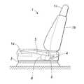
図1は、本発明が適用された自動車用シートの全体側面図である。シート1は、自動車のフロア2の上面にシートレール3を介して取り付けられている。シート1は、シートレール3に取り付けられた座席部1aと、例えばリクライニング可能に座席部1aに組み付けられた背もたれ1bと、背もたれ1bの上部に取り付けられたヘッドレスト1cとからなる。
【0012】
座席部1aの構造は、シートレール3の可動部と一体化された例えば矩形枠状のシートフレーム4と、座面の全面に渡って配設されるようにシートフレーム4に掛け渡された複数本のSばね(線ばねを連続するS字状に曲成したもの)5とからなる。それらSばね5と、その上に貼り付けられたウレタン製などのクッション材とによりシートクッション体が構成されている。
【0013】
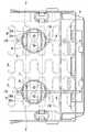
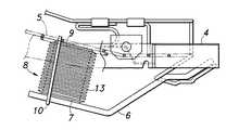
図2及び図3に併せて示されるように、シートフレーム4のシート後端側部分により片持ち支持された左右一対のロッド6が前方に向けて延出するように設けられていると共に、それらロッド6の延出端部にはシートの左右方向に延在するプレート7の両端部が固着されている。このようにして、シートの固定部としてプレート7が設けられている。
【0014】
そのプレート7と、シートクッション体の一部であるSばね5との間にダンパーとしてのベローズ8が設けられている。ベローズ8は、着座した乗員の臀部下部に位置する部分に左右に分かれて一対配設されている。各ベローズ8の下端部がプレート7にねじ止めにて結合され、各ベローズ8の上端部がSばね5の適所に円形のリング付きプレート9を介して結合されている。
【0015】
なお、図示例のシートフレーム4にあっては矩形枠状に形成されていることから、そのシート後端部に相当する部分から前方に向けて延出したロッド6にプレート7を介してベローズ8の下端部が結合されている構造としたが、これに限られるものではない。例えば皿状のシートフレームの場合には、その底部に直接またはブラケットを介してベローズ8の下端部を結合することができる。いずれにしても、シートクッション体の変位に対して固定部となる部分(スライドしない固定シートの場合にはフロアであって良い。)にベローズ8の一端部を固定すれば良い。
【0016】
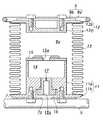
図に示されるように本ベローズ8にあっては、ロッド6に固着されたプレート7に結合される下端部を構成する下側部材11と、Sばね5に結合されるリング付きプレート9に結合される上側部材12と、両部材8a・8b間に設けられた蛇腹部13とにより内部に密閉空間が形成されるようになっている。なお、リング付きプレート9は、Sばね5の任意の箇所(図示例では4箇所)にジョイント19により結合できる大きさの径で形成されたリング9aと、そのリング9a内に受容されるように掛け渡さて一体化された平板9bとからなる。その平板9bに上側部材12がねじ止めされる。
【0017】
下側部材11は、ベローズ8の内部に受容される円柱状ブロック部11aと、そのブロック部11aと共にベローズ8の端面(下端面)を形成するようにブロック部11aの下端部に形成された外向フランジ部11bとを有する形状に形成されている。上側部材12は、ベローズ8の内部に受容される扁平円柱状のストッパ部12aと、そのストッパ部12aと共にベローズ8の端面(上端面)を形成するようにストッパ部12aの上端部に形成された外向フランジ部12bとを有する形状に形成されている。これら両外向フランジ部11b・12bの外周縁部に、ばね性蛇腹部として例えば弾性金属製の蛇腹部13の軸線方向両開口縁部が気密状態に固着されている。なお、蛇腹部13にあっては、ベローズ8の伸縮時に半径方向に大きく膨出変形しないものであれば金属以外の材質のものであっても良い。
【0018】
なお、ベローズ8の圧縮変形時にはブロック部11aの上面にストッパ部12aの下面が衝当して、それ以上の圧縮変形を規制しており、過大な外力の入力によりベローズ8が許容限度以上に圧縮変形することがないようにされている。また、ベローズ8の伸張変形に対しては、ロッド6(プレート7)とSばね5(リング付きプレート9)との間に掛け渡されたバンド10により規制されるようになっている。これにより、Sばね5の弾発復元力によりベローズ8が許容限度以上に伸張方向に変形することがない。さらに、バンド10の長さを調節することにより、ベローズ8をその取り付け状態で予荷重を付与する圧縮状態にして組み付けることができる。これにより、シートクッション体のばね特性の初期状態を変えることができ、任意のばね特性に変更可能になる。
【0019】
ブロック部11aの上半部にはベローズ8の内部に臨む凹設部14が形成されていると共に、その凹設部14の開口面を覆うようにブロック部11aの上面に蓋体15が固着されている。蓋体の中央部には凹設部14の内径より小径の開口15aが設けられている。ブロック部11aの下半部には、凹設部14の底面に開口するねじ孔が設けられ、そのねじ孔に栓16がねじ込まれて固設されている。その栓16には、凹設部14と連通するオリフィス17と、オリフィス17を介して凹設部14とブロック部11aの外方とを連通する孔16aが形成されている。なお、栓16には、ねじ部の気密性確保のためにOリングが取り付けられている。
【0020】
また、下側部材11の栓16を受容する凹設部とベローズ8の外部とを連通するべく、プレート7には開口7aが設けられている。これにより、ベローズ8の空室8aとベローズ8の外部とが、開口15aとオリフィス17と孔16aと開口7aとを介して連通している。なお、両開口15a・開口7a及び孔16aは、オリフィス17のオリフィス作用に影響を与えることがないように充分に大きな径で形成されている。このようにしてオリフィス付きベローズ8が構成されている。
【0021】
次に、本発明における自動車用シートにおける作用を以下に示す。従来例で示したように、人体の内蔵に最も影響のある振動が概ね6Hzのものであり、また近年の道路事情の良好化において生じる微振動において乗り心地に影響する振動が例えば8Hz近傍のものである。自動車用シートにあっては、これら各振動に対する振動伝達率を下げることが重要である。
【0022】
比較のために、シートクッション体をほとんどウレタン製パッドにより形成したもの(A・Bの各タイプ)におけるシート振動試験を行った結果を図5に示す。図において、横軸を変数としての振動数(Hz)とし、縦軸を振動伝達率とした。図では外部からの加振力としての振動数を約2Hz〜約9Hzとして、その振動数の変化に対する振動伝達率の変化を示している。
【0023】
例えばAタイプのもので、図の破線に示されるように概ね6Hz(5.5Hz程度)に共振点がある場合に、ほとんどウレタン製パッドで形成する場合には図の一点鎖線に示されるようにすることができる(Bタイプ)。このBタイプでは、共振点を概ね6Hzからずらすことができるが、それは概ね6Hzよりも高い所(7Hz程度)になり、そこでは上記乗り心地の悪化とみなされる微振動(8Hz近傍)の範囲に含まれてしまう。
【0024】
上記問題を解消するためには、共振点を上記6Hzよりも低い周波数帯にもっていくことが考えられる。例えばシートクッション体に多くのばねを設けたもの(ばねリッチ)を用いたものを試験した。これによれば、図5の想像線に示されるように共振点を5Hz近傍にずらすことができると共に、8Hz近傍の振動伝達率も下げることができ、上記微振動による乗り心地の悪化が解消される。
【0025】
しかしながら、このばねリッチ構造のシートにあっては、図5に示されるように、共振点における振動伝達率がまだ高いという問題がある。そのため、概ね6Hzにおける振動伝達率が充分に低いとは言い難い。また、5Hz近傍の共振点における振動伝達率が高いことにより、その振動数の入力による振動が速やかに収束しないという問題がある。これは、いわゆるホワンホワン感となって現れ、乗り心地の悪化となってしまう。
【0026】
それに対して本発明のシート構造のものでは図5の実線に示されるような結果が得られた。図に示されるように、共振点を上記ばねリッチのものよりもさらに低い方にずらすことができ(4Hz程度)、これにより概ね6Hz及び8Hz近傍での各振動伝達率を充分低いものとすることができた。また、オリフィス付きベローズ8を設けることにより振動伝達率の共振点のピーク値を低下させることができる。そのため、ばねリッチ(多数のSばね5を配設)だけでは共振点が低周波数化するがそのピーク値が上がるとしても、そのピーク値をオリフィス付きベローズの減衰効果により下げることができる。
【0027】
なお、上記図示例ではオリフィス付きベローズ8について示したが、本発明にあっては、ベローズ8に別部品からなるオリフィス17が設けられていることに限られるものではない。例えば下側部材11に、ベローズ8の伸縮時に減衰作用が生じる程度の孔が設けられていれば良い。また、ベローズ8の代わりに例えばオイルダンパーを設けても良い。
【0028】
【発明の効果】
このように本発明によれば、従来のばね体だけの構造によるシートクッション体ではなく、シートクッション体にダンパーを組み付けたことにより、シートクッション体に、ばね特性だけではなく減衰特性も作用させることができ、それにより共振点の変更及び共振ピーク値の低減が可能になるため、シートの乗り心地を良くすることができる。特に、ベローズにオリフィスを設けるという簡単な構造によりベローズにダンパー性能を特徴付けることができ、その場合にはばねとダンパーとの働きが生じ、シートの振動特性に有益な効果を奏し得る。また、ベローズがばね性蛇腹部を有していることにより、シートクッション体のばね特性を調整することができ、また、ベローズが取り付け状態で予荷重を付与する圧縮状態にされていることによれば、シートクッション体のばね特性の初期状態を任意の状態に変えることができ、ばね特性の調整が可能になるため、汎用性が高まり、種々の乗用車用シートに好適に適用し得る。
【図面の簡単な説明】
【図1】本発明が適用された自動車用シートの全体側面図。
【図2】シートの内部構造を示す要部平面図。
【図3】シートの内部構造を示す要部側面図。
【図4】ベローズを示す拡大縦断面図。
【図5】振動数に対する振動伝達率を示す図。
【符号の説明】
1 シート
4 シートフレーム
5 Sばね
6 ロッド
7 プレート
8 ベローズ
9 リング付きプレート
11 下側部材
12 上側部材
13 蛇腹部
17 オリフィス[0001]
TECHNICAL FIELD OF THE INVENTION
The present invention relates to an automobile seat.
[0002]
[Prior art]
It is known that among vibrations transmitted from a road surface to an occupant during running of a car, vibrations of about 6 Hz have the greatest effect on the internal of a human body. For this reason, there are cases where a sheet whose resonance point is shifted from about 6 Hz to either the high or low is used.
[0003]
However, with the recent improvement in road conditions, ride comfort against micro-vibration has been attracting attention. In the case of this minute vibration, the vibration is higher than about 6 Hz, for example, in the vicinity of 8 Hz. Even if the resonance point of the seat is deviated from about 6 Hz, if the resonance point is higher, the ride comfort is deteriorated due to the minute vibration. Would. Therefore, it has become important for recent automobile seats to reduce the vibration transmissibility of about 6 Hz or more.
[0004]
In order to prevent the micro vibration generated in the vehicle body from being transmitted to the seat, it is conceivable to provide a vibrating device or a vibration damping device that vibrates the seat in the opposite phase. For example, there is a type in which an air spring is provided below a seat (for example, see Patent Document 1), and it is conceivable to shift the resonance point by controlling the air spring.
[0005]
[Patent Document 1]
JP-A-05-245016 ([0011]-[0015], FIG. 1)
[0006]
[Problems to be solved by the invention]
However, when controlling the transmission of vibration to the seat using the air spring, not only the structure is complicated, such as an air pump for supplying air, an air chamber, and an air supply valve, but also a wide installation space is required. And there is a problem that the cost rises.
[0007]
[Means for Solving the Problems]
According to the present invention, a seated occupant is resiliently supported in order to solve such a problem and to realize a vehicle seat capable of improving ride comfort against microvibration with a simple structure. Vehicle seat having a seat cushion body for the vehicle, wherein a damper is provided between the seat cushion body and a fixing portion against displacement of the seat cushion body.
[0008]
According to this, since the movement at the time of displacement of the seat cushion body can be attenuated by the damper, the spring point is shifted to the low frequency side by using a lot of springs in the seat cushion body, and thereby the peak value of the resonance point is reduced. Even if it rises, the peak value can be lowered by the damper.
[0009]
In particular, since the damper is a bellows having an orifice, a damping effect can be obtained with a simple structure. In addition, since the bellows have the spring bellows, the spring characteristics of the seat cushion body can be adjusted. In addition, according to the bellows being in the compressed state in which a preload is applied in the mounted state, the initial state of the spring characteristic of the seat cushion body can be changed to an arbitrary state, and the spring characteristic can be adjusted. Become.
[0010]
BEST MODE FOR CARRYING OUT THE INVENTION
Hereinafter, embodiments of the present invention will be described in detail based on specific examples shown in the accompanying drawings.
[0011]
FIG. 1 is an overall side view of a vehicle seat to which the present invention is applied. The
[0012]
The structure of the seat portion 1a includes, for example, a rectangular frame-shaped seat frame 4 integrated with the movable portion of the
[0013]
As shown in FIGS. 2 and 3, a pair of left and
[0014]
A
[0015]
Since the seat frame 4 in the illustrated example is formed in a rectangular frame shape, a
[0016]
As shown in the figure, the
[0017]
The
[0018]
When the
[0019]
A
[0020]
Further, an
[0021]
Next, the operation of the vehicle seat according to the present invention will be described below. As shown in the conventional example, the vibration that most affects the built-in human body is approximately 6 Hz, and the vibration that affects the ride comfort in the slight vibration that occurs in recent years in improving road conditions is, for example, around 8 Hz. It is. In the case of an automobile seat, it is important to reduce the vibration transmissibility for each of these vibrations.
[0022]
For comparison, FIG. 5 shows the results of a seat vibration test performed on a seat cushion body (each type of A and B) in which the seat cushion body was formed almost entirely of urethane pads. In the figure, the horizontal axis represents the frequency (Hz) as a variable, and the vertical axis represents the vibration transmissibility. In the figure, the change in the vibration transmissibility with respect to the change in the frequency is shown with the frequency as the external excitation force being about 2 Hz to about 9 Hz.
[0023]
For example, in the case of the A type, when there is a resonance point at about 6 Hz (about 5.5 Hz) as shown by a broken line in the figure, when it is almost formed by a urethane pad, as shown by a dashed line in the figure, (B type). In this type B, the resonance point can be shifted from about 6 Hz, but it is higher than about 6 Hz (about 7 Hz). Will be included.
[0024]
In order to solve the above problem, it is conceivable to move the resonance point to a frequency band lower than 6 Hz. For example, a test was conducted using a seat cushion body provided with many springs (spring rich). According to this, as shown by the imaginary line in FIG. 5, the resonance point can be shifted to around 5 Hz, and the vibration transmissibility near 8 Hz can also be reduced, so that the deterioration of the riding comfort due to the above-mentioned minute vibration is eliminated. You.
[0025]
However, this spring-rich structure has a problem that the vibration transmissibility at the resonance point is still high, as shown in FIG. Therefore, it is difficult to say that the vibration transmissibility at about 6 Hz is sufficiently low. Further, since the vibration transmissibility at the resonance point near 5 Hz is high, there is a problem that the vibration due to the input of the frequency does not quickly converge. This appears as a so-called “one-of-a-kind” feeling, and the ride quality is degraded.
[0026]
On the other hand, in the case of the sheet structure of the present invention, the result shown by the solid line in FIG. 5 was obtained. As shown in the figure, the resonance point can be shifted further lower than the above-mentioned spring-rich one (about 4 Hz), so that the respective vibration transmissibility around 6 Hz and 8 Hz is sufficiently low. Was completed. Further, by providing the
[0027]
In the illustrated example, the
[0028]
【The invention's effect】
As described above, according to the present invention, not only the spring characteristic but also the damping characteristic is caused to act on the seat cushion body by attaching the damper to the seat cushion body instead of the conventional seat cushion body having only the spring body structure. As a result, the resonance point can be changed and the resonance peak value can be reduced, so that the riding comfort of the seat can be improved. In particular, the bellows can be characterized by its damper performance by a simple structure in which an orifice is provided in the bellows. In this case, a spring and a damper work, which can have a beneficial effect on the vibration characteristics of the seat. Further, since the bellows have a spring-like bellows portion, the spring characteristics of the seat cushion body can be adjusted, and the bellows is in a compressed state in which a preload is applied in a mounted state. If this is the case, the initial state of the spring characteristics of the seat cushion body can be changed to an arbitrary state, and the spring characteristics can be adjusted, so that the versatility is enhanced and the seat cushion body can be suitably applied to various passenger car seats.
[Brief description of the drawings]
FIG. 1 is an overall side view of an automobile seat to which the present invention is applied.
FIG. 2 is a main part plan view showing the internal structure of the seat.
FIG. 3 is a main part side view showing the internal structure of the seat.
FIG. 4 is an enlarged vertical sectional view showing a bellows.
FIG. 5 is a diagram showing a vibration transmission rate with respect to a frequency.
[Explanation of symbols]
DESCRIPTION OF
Claims (4)
Translated fromJapanese前記シートクッション体の変位に対する固定部と前記シートクッション体との間にダンパーが設けられていることを特徴とする自動車シート。An automobile seat having a seat cushion body for elastically supporting a seated occupant,
An automobile seat characterized in that a damper is provided between a fixing portion for displacement of the seat cushion body and the seat cushion body.
Priority Applications (1)
| Application Number | Priority Date | Filing Date | Title |
|---|---|---|---|
| JP2002295824AJP2004129751A (en) | 2002-10-09 | 2002-10-09 | Car seat |
Applications Claiming Priority (1)
| Application Number | Priority Date | Filing Date | Title |
|---|---|---|---|
| JP2002295824AJP2004129751A (en) | 2002-10-09 | 2002-10-09 | Car seat |
Publications (1)
| Publication Number | Publication Date |
|---|---|
| JP2004129751Atrue JP2004129751A (en) | 2004-04-30 |
Family
ID=32285965
Family Applications (1)
| Application Number | Title | Priority Date | Filing Date |
|---|---|---|---|
| JP2002295824APendingJP2004129751A (en) | 2002-10-09 | 2002-10-09 | Car seat |
Country Status (1)
| Country | Link |
|---|---|
| JP (1) | JP2004129751A (en) |
Citations (9)
| Publication number | Priority date | Publication date | Assignee | Title |
|---|---|---|---|---|
| JPS6335842U (en)* | 1986-08-21 | 1988-03-08 | ||
| JPH02134773A (en)* | 1988-11-15 | 1990-05-23 | Fujitsu Ltd | Stopper structure |
| JPH05269029A (en)* | 1992-03-27 | 1993-10-19 | Toyota Motor Corp | Vehicle seat and vehicle seat controller |
| JPH1054402A (en)* | 1996-08-09 | 1998-02-24 | Nhk Spring Co Ltd | Metal bellows accumulator |
| JPH10257936A (en)* | 1996-10-14 | 1998-09-29 | Protoned Bv | Chair mechanism and pad cover |
| JP2000035075A (en)* | 1998-07-16 | 2000-02-02 | Sumitomo Electric Ind Ltd | Air spring |
| JP2000043768A (en)* | 1998-07-31 | 2000-02-15 | Nissan Shatai Co Ltd | Module unit carrier device |
| JP2002017506A (en)* | 2000-07-11 | 2002-01-22 | Yamaha Motor Co Ltd | Seat for vehicle |
| JP2002204732A (en)* | 2000-09-28 | 2002-07-23 | Formway Furniture Ltd | Reclineable chair |
- 2002
- 2002-10-09JPJP2002295824Apatent/JP2004129751A/enactivePending
Patent Citations (9)
| Publication number | Priority date | Publication date | Assignee | Title |
|---|---|---|---|---|
| JPS6335842U (en)* | 1986-08-21 | 1988-03-08 | ||
| JPH02134773A (en)* | 1988-11-15 | 1990-05-23 | Fujitsu Ltd | Stopper structure |
| JPH05269029A (en)* | 1992-03-27 | 1993-10-19 | Toyota Motor Corp | Vehicle seat and vehicle seat controller |
| JPH1054402A (en)* | 1996-08-09 | 1998-02-24 | Nhk Spring Co Ltd | Metal bellows accumulator |
| JPH10257936A (en)* | 1996-10-14 | 1998-09-29 | Protoned Bv | Chair mechanism and pad cover |
| JP2000035075A (en)* | 1998-07-16 | 2000-02-02 | Sumitomo Electric Ind Ltd | Air spring |
| JP2000043768A (en)* | 1998-07-31 | 2000-02-15 | Nissan Shatai Co Ltd | Module unit carrier device |
| JP2002017506A (en)* | 2000-07-11 | 2002-01-22 | Yamaha Motor Co Ltd | Seat for vehicle |
| JP2002204732A (en)* | 2000-09-28 | 2002-07-23 | Formway Furniture Ltd | Reclineable chair |
Similar Documents
| Publication | Publication Date | Title |
|---|---|---|
| US4437653A (en) | Fluid-filled engine mount device | |
| JP5440705B2 (en) | Vehicle seat | |
| JP3049105B2 (en) | Bush type vibration damping device and bush type liquid filling vibration damping device | |
| JP4673798B2 (en) | Dynamic damper | |
| CN115230550A (en) | Vehicle seat back comprising at least one vibration device | |
| JP2008202609A (en) | Vibration damping device | |
| JP2004150546A (en) | Engine mount | |
| JPS6339458Y2 (en) | ||
| JP2005104425A (en) | Seat for vehicle | |
| JP2004129751A (en) | Car seat | |
| JP2005106192A (en) | Cylindrical engine mount | |
| JP7376808B2 (en) | vehicle seat | |
| CN116685498A (en) | Vehicle seat with headrest | |
| JP2007282865A (en) | Damper device for seat | |
| JP2022162037A (en) | vehicle seat | |
| JP6849930B2 (en) | Vehicle seat | |
| JP4047094B2 (en) | Vehicle seat back structure | |
| JP2002206591A (en) | Liquid filled type vibration damping device | |
| JP2003127743A (en) | Seta structure for automobile | |
| JP2001050330A (en) | Hydraulic buffering type mount | |
| JP4124369B2 (en) | Dynamic damper | |
| JP2007046699A (en) | Vehicle suspension system | |
| JP6777876B2 (en) | Vehicle seat | |
| JP2988653B2 (en) | Vehicle suspension | |
| JP2000168418A (en) | Vehicle seat |
Legal Events
| Date | Code | Title | Description |
|---|---|---|---|
| A621 | Written request for application examination | Free format text:JAPANESE INTERMEDIATE CODE: A621 Effective date:20040730 | |
| A977 | Report on retrieval | Free format text:JAPANESE INTERMEDIATE CODE: A971007 Effective date:20070425 | |
| A131 | Notification of reasons for refusal | Free format text:JAPANESE INTERMEDIATE CODE: A131 Effective date:20070508 | |
| A521 | Written amendment | Free format text:JAPANESE INTERMEDIATE CODE: A523 Effective date:20070706 | |
| A02 | Decision of refusal | Free format text:JAPANESE INTERMEDIATE CODE: A02 Effective date:20071016 |