JP2004129112A - Portable wireless communication device - Google Patents
Portable wireless communication deviceDownload PDFInfo
- Publication number
- JP2004129112A JP2004129112AJP2002293385AJP2002293385AJP2004129112AJP 2004129112 AJP2004129112 AJP 2004129112AJP 2002293385 AJP2002293385 AJP 2002293385AJP 2002293385 AJP2002293385 AJP 2002293385AJP 2004129112 AJP2004129112 AJP 2004129112A
- Authority
- JP
- Japan
- Prior art keywords
- mode
- audio output
- receiver
- frequency characteristic
- output device
- Prior art date
- Legal status (The legal status is an assumption and is not a legal conclusion. Google has not performed a legal analysis and makes no representation as to the accuracy of the status listed.)
- Pending
Links
- 230000005236sound signalEffects0.000claimsdescription9
- 238000010586diagramMethods0.000abstractdescription5
- 239000003990capacitorSubstances0.000description3
- 230000005540biological transmissionEffects0.000description2
- 230000003321amplificationEffects0.000description1
- 238000003199nucleic acid amplification methodMethods0.000description1
- 238000001228spectrumMethods0.000description1
Images


Landscapes
- Mobile Radio Communication Systems (AREA)
- Telephone Function (AREA)
Abstract
Translated fromJapaneseDescription
Translated fromJapanese【0001】
【発明の属する技術分野】
本発明は、音声通信を行う携帯型無線通信機に係り、とくに受信音声をレシーバモードとスピーカモードのいずれかを選択して出力できるようにした携帯型無線通信機に関する。
【0002】
【従来の技術】
音声通信を行う携帯型無線通信機には携帯電話機やトランシーバがあり、携帯電話機においては、使用者が受話部を耳に当て音声を聞く電話モードと、受話部から大きな音声を出力し耳を離して聞くハンズフリーモードの2種類の音声出力モードを有するものがある。また、業務用などの携帯型無線通信機(トランシーバ)においても、プレストーク送受話方式(単信)と同時送受話方式(複信)の二つのモードを有するものが一般的となっており、複信では使用者が受話部を耳に当て音声を聞くレシーバモードであり、単信では受話部から大きな音声を出力し耳を離して聞くスピーカモードとして使用する。
【0003】
図4は、従来の携帯型無線通信機受話系の構成例で、スピーカモード時に音声を出力する音声出力装置(スピーカ)44とレシーバモード時に音声を出力する音声出力装置(レシーバ)45が設けられている。アンテナ41から入力された受信波は受信部42で受信、復調処理され、音声信号は音声処理部43に送られる。この音声信号はスピーカモードの時に音声出力装置44から出力され、またレシーバモード時には別に設けられた音声出力装置45から出力される。多くの携帯型無線通信機ではこのように各モード対応に音声出力装置が設けられているが、1つの音声出力装置を各モードで共用する構成の携帯型無線通信機もある。
【0004】
【発明が解決しようとする課題】
スピーカモードでは音声出力装置から出力された音声振動は空間に広く伝播して耳に達するが、レシーバモードでは音声出力装置から出力された音声振動は狭い耳口内に直接入ってくる。このため、音声振動のレベルをレシーバモードではスピーカモードに比べて充分小さくすると同時に、音声振動の伝播路特性の違いから、音声出力装置から出力される音声信号の出力周波数スペクトルもそれぞれのモードに適したものとすることで聞きとり易さがよくなる。この聞きとり易さという点を考えると、各モードごとに別の音声出力装置を設けた図4のような構成では、音声出力装置自体の周波数特性や音声処理部43の音声出力装置44、45への各出力増幅器の周波数特性を調整することで、各モードごとの好ましい出力周波数特性を実現できる。一方、音声出力装置を各モードで共用するようにした構成では、何らかの対策を講じないとモード対応の出力周波数特性が同じになってしまう。しかし、図4のような構成は2つの音声出力装置を設けることから、1つの音声出力装置を共用する構成と比べると小型化、省スペース化、低価格化という点では不利である。
【0005】
本発明の目的は、スピーカモードとレシーバモードで1つの音声出力装置を共用した構成において、各モードで望ましい音声出力周波数特性をもたせるようにした携帯型無線通信機を提供することにある。
【0006】
【課題を解決するための手段】
本発明は、音声通信が可能で、ユーザが音声を聞くためのスピーカモードとレシーバモードを備えた携帯型無線通信機であって、
スピーカモードとレシーバモードの双方で1つの音声出力装置を共用するとともに、その音声出力装置への入力音声信号の周波数特性をスピーカモードかレシーバモードかに応じて切替えるための周波数特性切替手段を設けた携帯型無線通信機を開示する。
【0007】
【発明の実施の形態】
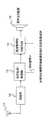
以下、本発明の実施の形態を説明する。図1は、本発明の携帯型無線通信機の受信系構成例を示すブロック図で、周波数特性切替手段14が設けられているのが特徴である。アンテナ11から入力された受信波は受信部12で受信、復調処理され、音声信号は音声処理・制御部13に送られる。音声処理・制御部13では通信モードがレシーバモードかスピーカモードかによって、また使用者によって設定された音声出力レベル等によって、音声信号の増幅、レベル調整等を行う。最終的に音声信号はスピーカ等の音声出力装置15から無線機外部に出力されるが、本発明では音声出力装置15に入力される音声信号を音声出力装置15に入力する前に、音声処理・制御部13からのレシーバモード又はスピーカモードであるかの通信モード判別信号Mによって、周波数特性を切替えられるような周波数特性切替手段14に通すことにより、レシーバモードとスピーカモードで異なる周波数特性を持たせることを可能にするものである。
【0008】
図2は、周波数特性切替手段14の構成例を示すもので、多重帰還型ローパスフィルタにアナログスイッチ21、コンデンサ22、23を付加し、アナログスイッチ21を制御することで周波数特性を切替えられるように構成されている。図3は、この図2の回路の周波数特性(振巾特性)の例を示したもので、コンデンサ22、23の容量をC1、C2として、R1=10kΩ、R2=68kΩ、R3=4.7kΩ、C1=0.01μF、C2=1000pFとした場合で、縦軸は振巾利得(dB)、横軸は周波数を示している。曲線SPで示す振巾特性はアナログスイッチ21をオフとしたときに得られ、曲線REで示した振巾特性はアナログスイッチ21をオンとしたときに得られる。
【0009】
そこでいま、音声出力装置15の周波数特性がほぼ音声帯域でフラットな特性とすると、スピーカモードのときはフラットな特性が好ましいので、判別信号Mがスピーカモードを示しているときにはアナログスイッチ21をオフとし、またレシーバモードのときは音声帯域高域部が強調された曲線REのような特性が好ましいので、判別信号Mがレシーバモードを示しているときにはアナログスイッチ21をオンするように制御する。このようにすることで、1つの音声出力装置をスピーカ/レシーバの両モードで共用した小型省スペース化、低価格化が可能な構成でも、両モードのそれぞれで好ましい音声出力の周波数特性を実現することができる。
【0010】
なお、スピーカモード、レシーバモードのいずれについても、ユーザが聞きとり易い周波数特性は、使用環境や使用する音声出力装置、無線機の筐体の音響特性などによって異なってくるが、周波数特性切替手段をこれらの条件を考慮したものとすることで容易に対応可能である。
【0011】
【発明の効果】
ユーザが受話部を耳に当て音声を聞くレシーバモード及び受話部から大きな音声を出力し耳を離して聞くスピーカモードのどちらのモードにおいても共通の音声出力装置を使用することにより、無線機の小型化、省スペース化、低コスト化が可能でかつ、スピーカモード、レシーバモードのいずれか、あるいは両方で音声出力部の周波数特性を変えることにより、それぞれのモードに適した周波数特性を設定することができる。
【図面の簡単な説明】
【図1】本発明の携帯型無線通信機の受信系構成例を示すブロック図である。
【図2】周波数特性切替手段の構成例を示す回路図である。
【図3】図2の回路の振巾特性例である。
【図4】従来の携帯型無線通信機の受信系構成例を示すブロック図である。
【符号の説明】
13 音声処理・制御部
14 周波数特性切替手段
15 音声出力装置
21 アナログスイッチ
22、23 コンデンサ[0001]
TECHNICAL FIELD OF THE INVENTION
The present invention relates to a portable wireless communication device for performing voice communication, and more particularly to a portable wireless communication device capable of outputting received voice by selecting one of a receiver mode and a speaker mode.
[0002]
[Prior art]
Portable wireless communicators that perform voice communication include mobile phones and transceivers. In mobile phones, there is a telephone mode in which the user touches the earpiece and listens to the voice. Some have two types of audio output modes, a hands-free mode for listening. In addition, a portable wireless communication device (transceiver) for business use and the like generally has two modes of a press talk transmission / reception system (simplex) and a simultaneous transmission / reception system (duplex), The duplex mode is a receiver mode in which a user puts a receiver on an ear to listen to a sound, and the simpler mode is a speaker mode in which a loud voice is output from the receiver and listens away from the ear.
[0003]
FIG. 4 shows a configuration example of a conventional portable wireless communication apparatus receiving system, in which an audio output device (speaker) 44 for outputting audio in a speaker mode and an audio output device (receiver) 45 for outputting audio in a receiver mode are provided. ing. The reception wave input from the antenna 41 is received and demodulated by the
[0004]
[Problems to be solved by the invention]
In the speaker mode, the sound vibration output from the sound output device propagates widely into the space and reaches the ear, whereas in the receiver mode, the sound vibration output from the sound output device directly enters the narrow ear opening. For this reason, the level of the sound vibration is made sufficiently smaller in the receiver mode than in the speaker mode, and the output frequency spectrum of the sound signal output from the sound output device is also suitable for each mode due to the difference in the propagation path characteristics of the sound vibration. It is easier to hear. Considering the ease of listening, in the configuration as shown in FIG. 4 in which another audio output device is provided for each mode, the frequency characteristics of the audio output device itself and the
[0005]
SUMMARY OF THE INVENTION It is an object of the present invention to provide a portable wireless communication device that has a desired audio output frequency characteristic in each mode in a configuration in which one audio output device is shared between a speaker mode and a receiver mode.
[0006]
[Means for Solving the Problems]
The present invention is a portable wireless communication device capable of voice communication and having a speaker mode and a receiver mode for a user to hear voice,
One audio output device is shared in both the speaker mode and the receiver mode, and frequency characteristic switching means for switching the frequency characteristic of an audio signal input to the audio output device according to the speaker mode or the receiver mode is provided. A portable wireless communication device is disclosed.
[0007]
BEST MODE FOR CARRYING OUT THE INVENTION
Hereinafter, embodiments of the present invention will be described. FIG. 1 is a block diagram showing a configuration example of a receiving system of a portable wireless communication device according to the present invention, which is characterized in that a frequency
[0008]
FIG. 2 shows an example of the configuration of the frequency characteristic switching means 14. An
[0009]
Now, assuming that the frequency characteristic of the
[0010]
In both the speaker mode and the receiver mode, the frequency characteristics that are easy for the user to hear vary depending on the use environment, the audio output device used, the acoustic characteristics of the wireless device housing, and the like. By taking these conditions into consideration, it is possible to easily cope with the situation.
[0011]
【The invention's effect】
By using a common audio output device in both the receiver mode in which the user puts the receiver on the ear and listens to the voice and the speaker mode in which the receiver outputs a loud voice and listens away from the ear, the size of the radio can be reduced. By changing the frequency characteristics of the audio output unit in either the speaker mode or the receiver mode or both, it is possible to set the frequency characteristics suitable for each mode. it can.
[Brief description of the drawings]
FIG. 1 is a block diagram illustrating a configuration example of a receiving system of a portable wireless communication device according to the present invention.
FIG. 2 is a circuit diagram illustrating a configuration example of a frequency characteristic switching unit.
FIG. 3 is an example of amplitude characteristics of the circuit of FIG. 2;
FIG. 4 is a block diagram illustrating a configuration example of a receiving system of a conventional portable wireless communication device.
[Explanation of symbols]
13 Audio processing /
Claims (1)
Translated fromJapaneseスピーカモードとレシーバモードの双方で1つの音声出力装置を共用するとともに、その音声出力装置への入力音声信号の周波数特性をスピーカモードかレシーバモードかに応じて切替えるための周波数特性切替手段を設けた携帯型無線通信機。A portable wireless communication device capable of voice communication and having a speaker mode and a receiver mode for a user to hear voice,
One audio output device is shared in both the speaker mode and the receiver mode, and frequency characteristic switching means for switching the frequency characteristic of an audio signal input to the audio output device according to the speaker mode or the receiver mode is provided. Portable wireless communicator.
Priority Applications (1)
| Application Number | Priority Date | Filing Date | Title |
|---|---|---|---|
| JP2002293385AJP2004129112A (en) | 2002-10-07 | 2002-10-07 | Portable wireless communication device |
Applications Claiming Priority (1)
| Application Number | Priority Date | Filing Date | Title |
|---|---|---|---|
| JP2002293385AJP2004129112A (en) | 2002-10-07 | 2002-10-07 | Portable wireless communication device |
Publications (1)
| Publication Number | Publication Date |
|---|---|
| JP2004129112Atrue JP2004129112A (en) | 2004-04-22 |
Family
ID=32284304
Family Applications (1)
| Application Number | Title | Priority Date | Filing Date |
|---|---|---|---|
| JP2002293385APendingJP2004129112A (en) | 2002-10-07 | 2002-10-07 | Portable wireless communication device |
Country Status (1)
| Country | Link |
|---|---|
| JP (1) | JP2004129112A (en) |
Cited By (1)
| Publication number | Priority date | Publication date | Assignee | Title |
|---|---|---|---|---|
| WO2020152907A1 (en)* | 2019-01-25 | 2020-07-30 | 株式会社ディーアンドエムホールディングス | Earphone device |
- 2002
- 2002-10-07JPJP2002293385Apatent/JP2004129112A/enactivePending
Cited By (4)
| Publication number | Priority date | Publication date | Assignee | Title |
|---|---|---|---|---|
| WO2020152907A1 (en)* | 2019-01-25 | 2020-07-30 | 株式会社ディーアンドエムホールディングス | Earphone device |
| JP2020120332A (en)* | 2019-01-25 | 2020-08-06 | 株式会社ディーアンドエムホールディングス | Earphone device |
| JP7396796B2 (en) | 2019-01-25 | 2023-12-12 | 株式会社ディーアンドエムホールディングス | earphone device |
| US12212913B2 (en) | 2019-01-25 | 2025-01-28 | D&M Holdings, Inc. | Earphone device |
Similar Documents
| Publication | Publication Date | Title |
|---|---|---|
| US6363139B1 (en) | Omnidirectional ultrasonic communication system | |
| CN104521247B (en) | Hearing aid and noise resisting method and device for Bluetooth headset | |
| US6445799B1 (en) | Noise cancellation earpiece | |
| US20090017878A1 (en) | Acoustic echo reduction in mobile terminals | |
| US20040131206A1 (en) | User selectable sound enhancement feature | |
| EP1911327A1 (en) | Method for equalizing inductive and acoustical signals, mobile device and computer program thereof | |
| JP2010527541A (en) | Communication device with ambient noise reduction function | |
| RU2424632C2 (en) | Device for radio communication with two-way audio signal | |
| JPH07107146A (en) | Cordless telephone device using bone conduction earphone microphone | |
| KR20070105555A (en) | Earphone with microphone | |
| WO2004004409A1 (en) | Mobile communication terminal | |
| US9942658B2 (en) | Method and apparatus for increasing audio output of a device | |
| KR100423705B1 (en) | A cellulra phone having function of a hearing aid | |
| JP2004129112A (en) | Portable wireless communication device | |
| KR20090103484A (en) | Blue tooth head set | |
| WO2009093890A1 (en) | Mobile phone, method of switching a mobile phone and use of a mobile phone | |
| JP4816338B2 (en) | Voice communication apparatus and voice output control method thereof | |
| CN113014706A (en) | Loudspeaker driving method and circuit for mobile equipment | |
| JP2586847B2 (en) | Electronic telephone | |
| JP7417073B2 (en) | Radio and its volume adjustment method | |
| KR20120115941A (en) | Apparatus and method for auto adjustment of volume in a portable terminal | |
| JPH0630090A (en) | Telephone set with sound volume control function | |
| KR20060023235A (en) | Mobile communication terminal with external noise cancellation | |
| KR200272789Y1 (en) | Enable tone control Audio Link System | |
| JP3717809B2 (en) | Mobile phone |
Legal Events
| Date | Code | Title | Description |
|---|---|---|---|
| A621 | Written request for application examination | Free format text:JAPANESE INTERMEDIATE CODE: A621 Effective date:20050330 | |
| A131 | Notification of reasons for refusal | Free format text:JAPANESE INTERMEDIATE CODE: A131 Effective date:20060530 | |
| A521 | Request for written amendment filed | Free format text:JAPANESE INTERMEDIATE CODE: A523 Effective date:20060731 | |
| A02 | Decision of refusal | Free format text:JAPANESE INTERMEDIATE CODE: A02 Effective date:20060822 |