JP2004128541A - Remote monitoring method and mobile phone - Google Patents
Remote monitoring method and mobile phoneDownload PDFInfo
- Publication number
- JP2004128541A JP2004128541AJP2002285558AJP2002285558AJP2004128541AJP 2004128541 AJP2004128541 AJP 2004128541AJP 2002285558 AJP2002285558 AJP 2002285558AJP 2002285558 AJP2002285558 AJP 2002285558AJP 2004128541 AJP2004128541 AJP 2004128541A
- Authority
- JP
- Japan
- Prior art keywords
- image
- motion vector
- data
- camera
- mobile phone
- Prior art date
- Legal status (The legal status is an assumption and is not a legal conclusion. Google has not performed a legal analysis and makes no representation as to the accuracy of the status listed.)
- Pending
Links
Images


Landscapes
- Closed-Circuit Television Systems (AREA)
- Telephone Function (AREA)
- Alarm Systems (AREA)
- Studio Devices (AREA)
- Selective Calling Equipment (AREA)
- Telephonic Communication Services (AREA)
Abstract
Description
Translated fromJapanese【0001】
【発明の属する技術分野】
本発明は、遠隔監視方法及び携帯電話機に関し、特に携帯電話機同士で遠隔監視を行う遠隔監視方法及び携帯電話機に関する。
【0002】
【従来の技術】
一般に、外出で留守した場合に自宅の様子が気になることがよくある。留守中に不審者が自宅に侵入し財産や高価な品物を盗まれてしまう事件も多発している。こうした世の中の状況からセキュリティ設備やシステムを販売し、サービスを行う事業者が増加している。ところが、システムやサービスはシステムを構築することやサービスを受けることに対して高額な費用が発生してしまう。また、システムやサービスにおける遠隔監視では、監視を行うのはサービスを行う事業者であり、本人は直接自宅の様子を確認できないという問題があった。
【0003】
これらの問題を解決する方法として、携帯電話機により自宅の様子を遠隔監視する方法が考えられる(例えば、特許文献1参照)。図6は、従来の携帯電話機を用いた遠隔監視システムの構成を示すブロック図である。この図において、従来の遠隔監視システムは、CCD(Charge Coupled Device)カメラ41及びCCDカメラ41を制御するコントローラユニット42からなる監視カメラ装置40と、公衆電話回線網N1と、移動体通信網N2と、受信した画像データを復号化して表示する機能を備えた携帯電話機10とを備えて構成される。
【0004】
コントローラユニット42は、CCDカメラ41から出力される映像信号の信号処理制御を統括するCPU(Central Processing Unit)42Aと、CCDカメラ41のオン・オフを行うスイッチング回路42Bと、CCDカメラ41とCPU42Aを接続するインタフェース回路42Cと、モデム42Fからの出力信号をCPU42Aに入力するCPU42Aのインタフェース回路42Dと、CPU42Aからの出力信号をモデム42Fに入力するインタフェース回路42Eと、携帯電話機10と通信するためのモデム42Fとを備えている。
【0005】
次に、上記構成の遠隔監視システムの動作について説明する。まず、携帯電話機10から監視カメラ装置40に電話をかけて、CCDカメラ41の電源を入れる。CCDカメラ41で撮影した画像はCPU42Aによって画像圧縮符号化された後、モデム42Fで信号変調処理が施されて公衆電話回線網N1に送出される。そして、移動体通信網N2を経由して送信された画像データを携帯電話機10で受信し、携帯電話機10に搭載されたLCD(Liquid Crystal Display)などの画像表示装置(図示略)に表示し、遠隔監視を行うものである。このように、従来の携帯電話機を用いた遠隔監視システムは、携帯電話機10側から電話をかけ、監視画像を取得するというものである。
【0006】
【特許文献1】
特開2002−27432号公報
【0007】
【発明が解決しようとする課題】
ところが、従来の携帯電話機を用いた遠隔監視システムにおいては、以下のような問題があった。すなわち、こちらが必要な時に対象物を監視できればよい場合は別として、前述したように留守宅の侵入者に対応するためには何らかの手段で常に監視を行う必要がある。従来の方法では、監視カメラ装置40に電話をかけて対象物の画像を取得している間は監視を行うことができるが、常に監視するには多額の電話代がかかってしまう。
【0008】
また、常に監視を行うと、携帯電話機10としての機能を失ってしまう。この問題を解決するには異常を通報する手段を別途設ける必要があるが、センサー等の異常検知手段と携帯電話機10に通報するための電話機が必要となり、これらを施設することも考慮すると多額の費用が発生してしまう。
【0009】
本発明は、このような実情に鑑みてなされたものであり、安価に且つ平易に遠隔監視を行うことができるような遠隔監視方法及び携帯電話機を提供することを目的とする。
【0010】
【課題を解決するための手段】
請求項1に係る発明の遠隔監視方法は、カメラを備えた携帯電話機による遠隔監視方法であって、前記カメラから入力される画像に対して動きベクトル検出を行い、動きベクトルを検出すると、予め登録されている通報先に電話をかけ、前記カメラから入力される画像及びマイクから入力される音声を前記通報先に送信することを特徴とする。
【0011】
この方法によれば、不審者の侵入等の異常を検出したときにのみ予め登録されている通報先に通報するので、通報先は通報を受けたときのみ監視現場の状況を確認するだけで済み、電話代を最小限に抑えることができる。すなわち、安価に且つ平易に遠隔監視を行うことができる。
【0012】
請求項2に係る発明の遠隔監視方法は、請求項1に係る発明の遠隔監視方法において、遠隔監視時には前記カメラと前記動きベクトル検出を行う回路のみ電源をオン状態として、前記カメラから入力される画像に対して前記動きベクトル検出を行い、動きベクトルを検出すると、前記カメラから入力される画像及び前記マイクから入力される音声を前記通報先に送信するために必要な回路の電源をオン状態とすることを特徴とする。
【0013】
この方法によれば、異常が発生していない状態では監視を行うために必要なカメラと動きベクトル検出を行う回路のみ電源をオンとするので、携帯電話機全体の電源を常時オンしたままの状態に比べて消費電力が低減し、長時間の監視が可能となる。
【0014】
請求項3に係る発明の遠隔監視方法は、請求項1又は請求項2に係る発明の遠隔監視方法において、前記カメラから入力される画像に対して前記動きベクトル検出を行い、動きベクトルを検出すると、1フレーム内で発生する各動きベクトルの大きさを計算し、動きベクトルの大きさの総和が最も大きい画像領域が画面の中心となるよう前記カメラの位置を制御することを特徴とする。
【0015】
この方法によれば、動きが大きい画像領域をカメラが自動的に追跡するので、異常を発生させている対象の画像を送信しつづけることが可能となり、通報先は瞬時に監視現場の状況を把握することが可能となる。
【0016】
請求項4に係る発明の遠隔監視方法は、請求項1乃至請求項3のいずれかに係る発明の遠隔監視方法において、前記カメラから入力される画像に対して前記動きベクトル検出を行い、動きベクトルを検出すると、前記カメラから入力される画像及び前記マイクから入力される音声を保存することを特徴とする。
【0017】
この方法によれば、異常発生時の状況を自動的に保存するので、異常発生時に通報先が電話にでることができなかった場合や電波を受信できなかった場合でも、後に保存された記録を確認することが可能となる。
【0018】
請求項5に係る発明の携帯電話機は、画像を撮影する画像撮影手段と、音声を取得する音声取得手段と、前記画像撮影手段で撮影された画像を符号化する画像符号化手段と、前記音声取得手段で取得された音声を符号化する音声符号化手段と、前記画像符号化手段からの画像データ及び前記音声符号化手段からの音声データを多重化するデータ多重化手段と、前記画像撮影手段からの画像信号から画像の動きベクトルを検出する動きベクトル検出手段と、前記動きベクトル検出手段にて動きベクトルが検出されると、予め登録されている通報先に電話をかけて多重化された画像データ及び音声データを送信する制御を行う通信制御手段と、を具備することを特徴とする。
【0019】
この構成によれば、不審者の侵入等の異常を検出したときにのみ予め登録されている通報先に通報するので、通報先は通報を受けたときのみ監視現場の状況を確認するだけで済み、電話代を最小限に抑えることができる。また、もともと画像符号化処理の一部である動きベクトル検出処理を利用することで、携帯電話機の価格の上昇を最小限に抑えることができる。すなわち、安価に且つ平易に遠隔監視を行うことができる。
【0020】
請求項6に係る発明の携帯電話機は、請求項5に係る発明の携帯電話機において、前記画像撮影手段と前記動きベクトル検出手段の電源を主電源オフ時以外常時オン状態とし、前記動きベクトル検出手段にて動きベクトルが検出されると前記音声取得手段、前記画像符号化手段、前記音声符号化手段、前記データ多重化手段及び前記通信制御手段夫々の電源をオン状態とする電源制御手段を更に具備することを特徴とする。
【0021】
この構成によれば、異常が発生していない状態では監視を行うために必要な画像撮影手段と動きベクトル検出手段の電源のみをオン状態とするので、携帯電話機全体の電源を常時オンしたままの状態に比べて消費電力が低減し、長時間の監視が可能となる。
【0022】
請求項7に係る発明の携帯電話機は、請求項5又は請求項6に係る発明の携帯電話機において、前記動きベクトル検出手段にて動きベクトルが検出されると、1フレーム内で発生する各動きベクトルの大きさを計算し、動きベクトルの大きさの総和が最も大きい画像領域が画面の中心となるよう前記画像撮影手段の向きを調整する方向調整手段を更に具備することを特徴とする。
【0023】
この構成によれば、動きが大きい画像領域を画像撮影手段が自動的に追跡するので、異常を発生させている対象の画像を送信しつづけることが可能となり、通報先は瞬時に監視現場の状況を把握することが可能となる。
【0024】
請求項8に係る発明の携帯電話機は、請求項5乃至請求項7のいずれかに係る発明の携帯電話機において、データを記録する記録手段と、前記動きベクトル検出手段にて動きベクトルが検出されると、前記データ多重化手段からの多重化された画像データ及び音声データを前記記録手段に記録する記録制御手段と、を更に具備することを特徴とする。
【0025】
この構成によれば、異常発生時の状況を自動的に記録するので、異常発生時に通報先が電話にでることができなかった場合や電波を受信できなかった場合でも、後に記録を確認することが可能となる。
【0026】
請求項9に係る発明の携帯電話機は、受信信号を画像データと音声データに分離するデータ分離手段と、前記データ分離手段で分離された前記画像データを復号化する画像データ復号化手段と、前記データ分離手段で分離された前記音声データを復号化する音声データ復号化手段と、前記画像データ復号化手段で復号化された画像を表示する画像表示手段と、前記音声データ復号化手段で復号化された音声を出力する音声出力手段と、を具備することを特徴とする。
【0027】
この構成によれば、電波の受信可能な場所であれば、何時でも何処でも監視画像を受信することができるので、必要なときに現場の状況を確認することができる。
【0028】
請求項10に係る発明の遠隔監視システムは、請求項5乃至請求項8のいずれかに係る発明の携帯電話機と、請求項9に係る発明の携帯電話機と、これらの携帯電話機間を接続する移動体通信網と、を具備することを特徴とする。
【0029】
この構成によれば、テレビ電話機能をもつ携帯電話機を用いるので、安価に且つ平易に遠隔監視システムを構築することができる。
【0030】
【発明の実施の形態】
以下、本発明の実施の形態について、図面を用いて詳細に説明する。
【0031】
(実施の形態1)
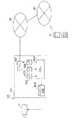
図1は、本発明の実施の形態1に係る携帯電話機の構成を示すブロック図である。この図において、本実施の形態の携帯電話機は、CCDカメラ101、マイク102、動きベクトル検出部103、通信制御部104、電源制御部105、カメラ制御部106、蓄積制御部107、画像符号化部108、音声符号化部109、データ多重化部110、メモリ111、伝送路符号化部112、信号送受信部113、伝送路復号化部114、データ分離部115、画像復号化部116、音声復号化部117、画像表示部118及びスピーカ119を備えている。
【0032】
CCDカメラ101は監視画像を入力する。マイク102は音声を入力する。動きベクトル検出部103は入力画像と1フレーム前の画像を比較して動きベクトルを検出する。通信制御部104は動きベクトルが検出されたことを示す信号を受けると、予め登録されている電話番号に電話をかける制御を行う。電源制御部105は動きベクトルが検出されたことを示す信号を受けると、CCDカメラ101及び動きベクトル検出部103以外の電源をオンにする制御を行う。
【0033】
カメラ制御部106は、動きベクトルが検出されたことを示す信号を受けると、1フレーム内で発生した動きベクトルの大きさを計算し、動きベクトルの大きさの総和が最も大きい領域がフレームの中心となるようCCDカメラ101の向きを制御する。蓄積制御部107は、動きベクトルが検出されたことを示す信号を受けると、データ多重化部110を制御して、画像データと音声データを多重化したデータをメモリ111に記録する。
【0034】
画像符号化部108は、CCDカメラ101からの入力画像を圧縮符号化する。音声符号化部109は、マイク102からの入力音声を圧縮符号化する。データ多重化部110は、圧縮符号化した画像データと音声データを多重化する。メモリ111は、画像データと音声データを多重化したデータを蓄積する。伝送路符号化部112は、多重化データを移動体通信網に送信するための処理を行う。
【0035】
信号送受信部113は、伝送路符号化された信号を移動体通信網へ送信し、また移動体通信網より受信する。伝送路復号化部114は、移動体通信網より受信した信号を復号化する。データ分離部115は、受信した多重化データを画像データと音声データに分離する。画像復号化部116は、分離された画像データを復号化する。音声復号化部117は、分離された音声データを復号化する。画像表示部118は、復号化された画像信号を表示する。スピーカ119は、復号化された音声信号を出力する。
【0036】
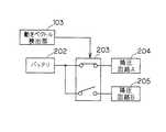
ここで、監視開始時の電源制御部105の状態を図2に示す。この図において、202は本携帯電話機に搭載されているバッテリ、203はバッテリ202からの電流をオン/オフするスイッチ、204はCCDカメラ101と動きベクトル検出部103へ電源を供給する降圧回路A、205はCCDカメラ101と動きベクトル検出部103以外へ電源を供給する降圧回路Bである。電源制御部105が動きベクトル検出部103から動きベクトル検出信号を受けていない状態では、CCDカメラ101と動きベクトル検出部103のみ電源がオンとなる。一方、電源制御部105が動きベクトル検出部103から動きベクトル検出信号を受けた場合、図3に示すようにCCDカメラ101と動きベクトル検出部103以外の部分の電源もオンとなる。
【0037】
次に、本実施の形態の携帯電話機の動作について説明する。まず、本携帯電話機を監視したい場所に設置する。動きベクトルが発生していない状態ではCCDカメラ101と動きベクトル検出部103のみ電源がオンとなり、それ以外の部分は電源がオフとなる。監視中に不審者の侵入等により、監視画像に動きが検出された場合は、動きベクトル検出部103により動きベクトルが検出されて、動きベクトル検出信号が出力される。
【0038】
動きベクトル検出信号が出力されると、通信制御部104が予め登録されている電話番号に電話をかけるよう信号送受信部113を制御する。また、動きベクトル検出信号が出力されると、カメラ制御部106が1フレーム内に発生した動きベクトルの大きさを計算し、各領域ごとに動きベクトルの大きさの総和を求める。そして、動きベクトルの大きさの総和が最も大きい領域がフレームの中心となるようにCCDカメラ101の方向を調整する。
【0039】
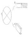
ここで、動きベクトルの大きさの総和を求める領域分割及びカメラ制御の例を図4に示す。図4(a)は1フレームの領域分割の例を示している。QCIF(Quarter Common Intermediate Format)画像は176画素×144画素で構成され、これを画像符号化の単位であるマクロブロック(16画素×16画素、以降MBと記す)単位で区切ると図のように11MB×9MBとなる。これを3MB×3MBの領域に分割すると図のように9つの領域に分割することができる。
【0040】
動きベクトルはMB単位で算出されるため、1つの領域毎に9つの動きベクトルが求められる。これらの動きベクトルの大きさの総和を各領域毎に計算し、最も値の大きい領域を求める。図4(b)に示す例では領域9がそれに相当することを示している。そして領域9がフレームの中心となるよう、図4(c)に示すように、CCDカメラ101の方向を右斜め下へ動かす。侵入者等の動きのある部分をCCDカメラ101が追跡することで、通報先は瞬時に異常の原因を把握することができる。CCDカメラ101からの入力画像、マイク102からの入力音声は画像符号化部108、音声符号化部109によりそれぞれ情報量圧縮、符号化の処理が行われる。
【0041】
符号化後の画像データ及び音声データはデータ多重化部110でパケット化されてストリームデータが生成される。蓄積制御部107は、動きベクトル検出信号を受けることで、多重化されたストリームデータをメモリ111に蓄積するようにデータ多重化部110を制御する。
【0042】
多重化されたビットストリームデータは伝送路符号化部112に入力されて、誤り訂正符号化や無線チャネルフォーマットへの組み立て等の伝送路符号化が行われる。そして、伝送路符号化処理されたビットストリームデータが信号送受信部113に入力される。信号送受信部113は、異常状態の情報を送信すべく伝送路符号化処理された信号を変調し、周波数変換を行い、図示せぬアンテナより送信する。
【0043】
また、信号送受信部113は、異常状態の情報を受信すべく、図示せぬアンテナより受信した信号を周波数変換して復調する。伝送路復号化部114では、復調された受信データに対して無線チャネルフォーマットからのデータ分離、誤り訂正復号等の伝送路復号化処理が行われて、その結果がデータ分離部115に入力される。データ分離部115では、多重化されている音声データと画像データの分離が行われる。分離された画像データは画像復号化部116に入力される。また、分離された音声データは音声復号化部117に入力される。そして、画像復号化部116で復号化された画像信号が画像表示部118に表示される。また、音声復号化部117で復号化された音声信号はスピーカ119により出力される。
【0044】
このように、本実施の形態の携帯電話機によれば、不審者の侵入等の異常を検出したときにのみ予め登録されている通報先に通報するので、通報先は通報を受けたときのみ監視現場の状況を確認するだけで済み、電話代を最小限に抑えることができる。また、もともと画像符号化処理の一部である動きベクトル検出処理を利用することと、監視中はCCDカメラ101と動きベクトル検出部103のみ電源をオンとするので、携帯電話機の消費電力を低減でき、長時間の監視を実現することができる。
【0045】
また、異常を検出したときに、動きのある領域をCCDカメラ101で追跡するとともに音声を拾うので、通報先は異常通報を受けた瞬間から監視現場の状況を把握することができる。また、異常を検出した時点からの状況をメモリ111に蓄積するので、通報先が異常通報を受信できなかった、もしくは電話に出ることができなかった場合でも後に状況を確認することができる。
【0046】
なお、本実施の形態の携帯電話機は、画像と音声を通報先に送信するための監視手段と、受信データから画像データと音声データを分離して画像表示及び音声出力を行う通報受信手段とを有しているが、いずれか一方のみ有しても良い。すなわち、監視機能のみ有する携帯電話機と通報受信機能のみ有する携帯電話機としても良い。専用にすると携帯電話機自体の単価を安くすることができる。
【0047】
(実施の形態2)
図5は、実施の形態1の携帯電話機を利用した遠隔監視システムの構成を示すブロック図である。この図において、501は実施の形態1の携帯電話機であり、監視側端末である。502は携帯電話機501であり、通報受信側端末である。503は移動体通信網である。
【0048】
監視を行いたい場所に監視側端末501を設置するとともにCCDカメラ101を監視の対象に向けておく。不審者の侵入等が発生した場合、実施の形態1で説明したとおり、監視側端末501は予め登録されている通報受信側端末502に電話をかけるべく移動体通信網503に接続する。移動体通信網503は通報受信側端末502に対して接続要求を行い、通報受信側端末502は移動体通信網503と接続を行う。移動体通信網503を介して監視側端末501と通報受信側端末502が接続されると、通報受信側端末502の画像表示部118に監視現場の画像が表示され、またスピーカ119から監視現場の音声が出力される。
【0049】
このように、本実施の形態の遠隔監視システムによれば、実施の形態1の携帯電話機を複数台用いるので、安価に且つ平易に遠隔監視システムを実現することができる。
【0050】
なお、監視側端末501を監視機能のみ有する携帯電話機とし、通報受信側端末502を通報受信機能のみ有する携帯電話機としても良い。
【0051】
【発明の効果】
上述した説明から明らかなように、本発明の遠隔監視方法及び携帯電話機によれば、不審者の侵入等の異常を検出したときにのみ予め登録されている通報先に通報するので、通報先は通報を受けたときのみ監視現場の状況を確認するだけで済み、電話代を最小限に抑えることができる。すなわち、安価に且つ平易に遠隔監視を行うことができる。
【図面の簡単な説明】
【図1】本発明の実施の形態1に係る携帯電話機の構成を示すブロック図である。
【図2】図1の携帯電話機における監視開始時の電源制御部の状態を示すブロック図である。
【図3】図1の携帯電話機における通報時の電源制御部の状態を示すブロック図である。
【図4】図1の携帯電話機における領域分割及びカメラ制御の例を説明するための図である。
【図5】本発明の実施の形態2に係る遠隔監視システムの構成を示すブロック図である。
【図6】従来の遠隔監視システムの構成を示すブロック図である。
【符号の説明】
101 CCDカメラ
102 マイク
103 動きベクトル検出部
104 通信制御部
105 電源制御部
106 カメラ制御部
107 蓄積制御部
108 画像符号化部
109 音声符号化部
110 データ多重化部
111 メモリ
112 伝送路符号化部
113 信号送受信部
114 伝送路復号化部
115 データ分離部
116 画像復号化部
117 音声復号化部
118 画像表示部
119 スピーカ
202 バッテリ
203 スイッチ
204 降圧回路A
205 降圧回路B
501 監視側端末
502 通報受信側端末
503 移動体通信網[0001]
TECHNICAL FIELD OF THE INVENTION
The present invention relates to a remote monitoring method and a mobile phone, and more particularly, to a remote monitoring method and a mobile phone for performing remote monitoring between mobile phones.
[0002]
[Prior art]
In general, when one is away from home, the state of the home is often anxious. There have been many incidents of suspicious individuals invading their homes while away and stealing property and valuable items. Under such circumstances, the number of companies that sell security equipment and systems and provide services is increasing. However, systems and services require high costs for constructing the systems and receiving the services. Further, in remote monitoring of systems and services, there is a problem that the service provider monitors the service, and the person cannot directly check the state of his / her home.
[0003]
As a method of solving these problems, a method of remotely monitoring the state of the house with a mobile phone is conceivable (for example, see Patent Document 1). FIG. 6 is a block diagram showing a configuration of a remote monitoring system using a conventional mobile phone. In FIG. 1, a conventional remote monitoring system includes a
[0004]
The
[0005]
Next, the operation of the remote monitoring system having the above configuration will be described. First, a call is made from the mobile phone 10 to the
[0006]
[Patent Document 1]
Japanese Patent Application Laid-Open No. 2002-27432
[Problems to be solved by the invention]
However, the conventional remote monitoring system using a mobile phone has the following problems. That is, apart from the case where the object can be monitored when it is necessary, it is necessary to always monitor by some means in order to respond to the intruder in the absence house as described above. In the conventional method, monitoring can be performed while an image of the object is acquired by calling the
[0008]
Further, if monitoring is always performed, the function as the mobile phone 10 is lost. In order to solve this problem, it is necessary to separately provide a means for reporting an abnormality. However, an abnormality detecting means such as a sensor and a telephone for reporting to the mobile phone 10 are required. You will incur costs.
[0009]
The present invention has been made in view of such circumstances, and an object of the present invention is to provide a remote monitoring method and a mobile phone capable of performing remote monitoring easily and inexpensively.
[0010]
[Means for Solving the Problems]
The remote monitoring method according to the first aspect of the present invention is a remote monitoring method using a mobile phone provided with a camera, wherein a motion vector is detected for an image input from the camera, and when a motion vector is detected, the image is registered in advance. A telephone call is made to the notified destination, and an image input from the camera and a voice input from the microphone are transmitted to the notified destination.
[0011]
According to this method, a notification is sent to a pre-registered report destination only when an abnormality such as intrusion of a suspicious person is detected, so the report destination only needs to check the status of the monitoring site only when receiving the report. , Telephone charges can be minimized. That is, remote monitoring can be performed inexpensively and easily.
[0012]
A remote monitoring method according to a second aspect of the present invention is the remote monitoring method according to the first aspect of the present invention, wherein during the remote monitoring, only the camera and the circuit for performing the motion vector detection are turned on and input from the camera. Performing the motion vector detection on the image, when the motion vector is detected, the power of the circuit necessary to transmit the image input from the camera and the voice input from the microphone to the notification destination is turned on. It is characterized by doing.
[0013]
According to this method, only the camera necessary for monitoring and the circuit for performing motion vector detection are turned on in a state where no abnormality has occurred, so that the power of the entire mobile phone is always kept on. Compared with this, power consumption is reduced, and monitoring can be performed for a long time.
[0014]
A remote monitoring method according to a third aspect of the present invention is the remote monitoring method according to the first or second aspect, wherein the motion vector detection is performed on an image input from the camera, and the motion vector is detected. The method is characterized in that the magnitude of each motion vector generated in one frame is calculated, and the position of the camera is controlled so that the image area having the largest sum of the magnitudes of the motion vectors becomes the center of the screen.
[0015]
According to this method, the camera automatically tracks the image area with large motion, so it is possible to continue transmitting the image of the target causing the abnormality, and the report destination can immediately grasp the situation of the monitoring site It is possible to do.
[0016]
A remote monitoring method according to a fourth aspect of the present invention is the remote monitoring method according to any one of the first to third aspects, wherein the motion vector detection is performed on an image input from the camera. Is detected, the image input from the camera and the audio input from the microphone are stored.
[0017]
According to this method, the situation at the time of the occurrence of an abnormality is automatically saved, so even if the destination of the report cannot be reached or the radio wave cannot be received at the time of the occurrence of the abnormality, the saved record can be saved later. It is possible to confirm.
[0018]
An image photographing means for photographing an image, a sound acquiring means for acquiring sound, an image encoding means for encoding an image photographed by the image photographing means, Audio encoding means for encoding the audio acquired by the acquiring means, data multiplexing means for multiplexing the image data from the image encoding means and the audio data from the audio encoding means, and the image photographing means A motion vector detecting means for detecting a motion vector of an image from an image signal from the apparatus; and, when a motion vector is detected by the motion vector detecting means, a call is made to a pre-registered report destination to multiplex the multiplexed image. Communication control means for controlling transmission of data and voice data.
[0019]
According to this configuration, only when an abnormality such as intrusion of a suspicious person is detected, a notification is sent to a pre-registered report destination. Therefore, the report destination only needs to check the status of the monitoring site only when receiving the report. , Telephone charges can be minimized. In addition, by using the motion vector detection processing which is originally a part of the image coding processing, it is possible to minimize an increase in the price of the mobile phone. That is, remote monitoring can be performed inexpensively and easily.
[0020]
A mobile phone according to a sixth aspect of the present invention is the mobile phone according to the fifth aspect, wherein the power of the image photographing means and the motion vector detecting means is always on except when the main power is off. Further comprising a power supply control unit for turning on the power of each of the audio acquisition unit, the image encoding unit, the audio encoding unit, the data multiplexing unit, and the communication control unit when a motion vector is detected. It is characterized by doing.
[0021]
According to this configuration, in a state where no abnormality occurs, only the power of the image capturing unit and the motion vector detecting unit necessary for monitoring is turned on, so that the power of the entire mobile phone is always kept on. Power consumption is reduced as compared with the state, and monitoring for a long time can be performed.
[0022]
According to a seventh aspect of the present invention, in the mobile phone according to the fifth or sixth aspect, when a motion vector is detected by the motion vector detecting means, each motion vector generated within one frame is detected. And a direction adjusting unit that adjusts the direction of the image photographing unit so that the image area having the largest sum of the magnitudes of the motion vectors becomes the center of the screen.
[0023]
According to this configuration, since the image photographing means automatically tracks the image area having a large movement, it is possible to continuously transmit the image of the target in which the abnormality is occurring, and the notification destination is instantaneously notified of the situation at the monitoring site. Can be grasped.
[0024]
According to an eighth aspect of the present invention, in the mobile phone according to any one of the fifth to seventh aspects, a recording unit for recording data and a motion vector are detected by the motion vector detecting unit. And recording control means for recording the multiplexed image data and audio data from the data multiplexing means in the recording means.
[0025]
According to this configuration, the situation at the time of the occurrence of an abnormality is automatically recorded. Therefore, even if the report destination cannot answer the telephone or cannot receive the radio wave at the time of the abnormality, the recording can be confirmed later. Becomes possible.
[0026]
The portable telephone according to the ninth aspect of the present invention is a mobile phone, comprising: a data separation unit that separates a received signal into image data and audio data; an image data decoding unit that decodes the image data separated by the data separation unit; Audio data decoding means for decoding the audio data separated by the data separation means, image display means for displaying an image decoded by the image data decoding means, and decoding by the audio data decoding means Voice output means for outputting the generated voice.
[0027]
According to this configuration, the monitoring image can be received anytime and anywhere as long as the location where radio waves can be received, so that the situation at the site can be checked when necessary.
[0028]
A remote monitoring system according to a tenth aspect of the present invention provides a remote monitoring system according to any one of the fifth to eighth aspects, a mobile phone according to the ninth aspect, and a mobile device connecting these mobile phones. And a body communication network.
[0029]
According to this configuration, since a mobile phone having a videophone function is used, a remote monitoring system can be constructed inexpensively and easily.
[0030]
BEST MODE FOR CARRYING OUT THE INVENTION
Hereinafter, embodiments of the present invention will be described in detail with reference to the drawings.
[0031]
(Embodiment 1)
FIG. 1 is a block diagram showing a configuration of the mobile phone according to Embodiment 1 of the present invention. In this figure, a mobile phone according to the present embodiment includes a
[0032]
The
[0033]
Upon receiving the signal indicating that the motion vector has been detected, the
[0034]
The
[0035]
The signal transmission /
[0036]
Here, FIG. 2 shows a state of the power
[0037]
Next, the operation of the mobile phone according to the present embodiment will be described. First, place the mobile phone at the place where you want to monitor. When no motion vector is generated, only the
[0038]
When the motion vector detection signal is output, the
[0039]
Here, an example of area division and camera control for obtaining the sum of the magnitudes of the motion vectors is shown in FIG. FIG. 4A shows an example of area division of one frame. A QCIF (Quarter Common Intermediate Format) image is composed of 176 pixels × 144 pixels, and when this image is divided into macroblocks (16 pixels × 16 pixels, hereinafter referred to as MB) which are units of image encoding, 11 MB as shown in the figure. × 9 MB. If this is divided into 3 MB × 3 MB regions, it can be divided into nine regions as shown in the figure.
[0040]
Since the motion vectors are calculated in MB units, nine motion vectors are obtained for each region. The sum of the magnitudes of these motion vectors is calculated for each region, and the region having the largest value is obtained. The example shown in FIG. 4B shows that the
[0041]
The encoded image data and audio data are packetized by the
[0042]
The multiplexed bit stream data is input to the transmission
[0043]
Further, the signal transmitting / receiving
[0044]
As described above, according to the mobile phone of the present embodiment, a report is sent to a pre-registered report destination only when an abnormality such as intrusion of a suspicious person is detected. You only need to check the situation at the site, minimizing telephone charges. In addition, the power consumption of the mobile phone can be reduced by using the motion vector detection process which is originally a part of the image coding process and turning on only the power of the
[0045]
Further, when an abnormality is detected, a moving area is tracked by the
[0046]
The mobile phone according to the present embodiment includes monitoring means for transmitting images and sounds to a report destination, and report receiving means for separating image data and sound data from received data and performing image display and sound output. However, only one of them may be provided. That is, a mobile phone having only the monitoring function and a mobile phone having only the report receiving function may be used. The exclusive use can reduce the unit price of the mobile phone itself.
[0047]
(Embodiment 2)
FIG. 5 is a block diagram illustrating a configuration of a remote monitoring system using the mobile phone according to the first embodiment. In this figure,
[0048]
The
[0049]
As described above, according to the remote monitoring system of the present embodiment, since a plurality of the mobile phones of the first embodiment are used, a remote monitoring system can be realized inexpensively and easily.
[0050]
Note that the
[0051]
【The invention's effect】
As is clear from the above description, according to the remote monitoring method and the mobile phone of the present invention, a notification is sent to a previously registered destination only when an abnormality such as intrusion of a suspicious person is detected. It is only necessary to check the status of the monitoring site only when receiving a report, and it is possible to minimize telephone charges. That is, remote monitoring can be performed inexpensively and easily.
[Brief description of the drawings]
FIG. 1 is a block diagram showing a configuration of a mobile phone according to Embodiment 1 of the present invention.
FIG. 2 is a block diagram showing a state of a power supply control unit when monitoring is started in the mobile phone of FIG.
FIG. 3 is a block diagram showing a state of a power control unit at the time of notification in the mobile phone of FIG. 1;
FIG. 4 is a diagram illustrating an example of area division and camera control in the mobile phone of FIG. 1;
FIG. 5 is a block diagram showing a configuration of a remote monitoring system according to Embodiment 2 of the present invention.
FIG. 6 is a block diagram showing a configuration of a conventional remote monitoring system.
[Explanation of symbols]
101
205 Step-down circuit B
501
Claims (10)
Translated fromJapanesePriority Applications (1)
| Application Number | Priority Date | Filing Date | Title |
|---|---|---|---|
| JP2002285558AJP2004128541A (en) | 2002-09-30 | 2002-09-30 | Remote monitoring method and mobile phone |
Applications Claiming Priority (1)
| Application Number | Priority Date | Filing Date | Title |
|---|---|---|---|
| JP2002285558AJP2004128541A (en) | 2002-09-30 | 2002-09-30 | Remote monitoring method and mobile phone |
Publications (1)
| Publication Number | Publication Date |
|---|---|
| JP2004128541Atrue JP2004128541A (en) | 2004-04-22 |
Family
ID=32278829
Family Applications (1)
| Application Number | Title | Priority Date | Filing Date |
|---|---|---|---|
| JP2002285558APendingJP2004128541A (en) | 2002-09-30 | 2002-09-30 | Remote monitoring method and mobile phone |
Country Status (1)
| Country | Link |
|---|---|
| JP (1) | JP2004128541A (en) |
Cited By (10)
| Publication number | Priority date | Publication date | Assignee | Title |
|---|---|---|---|---|
| JP2005328541A (en)* | 2004-05-12 | 2005-11-24 | Mitsubishi Electric Research Laboratories Inc | Surveillance system and method |
| WO2008067236A3 (en)* | 2006-11-29 | 2008-09-12 | Honeywell Int Inc | Apparatus and method for inspecting assets in a processing or other environment |
| JP2008282181A (en)* | 2007-05-10 | 2008-11-20 | Nohmi Bosai Ltd | Home security equipment, terminal of home security equipment, disaster prevention service provision method, contracting method for fire alarm service and fire alarm |
| US8059882B2 (en) | 2007-07-02 | 2011-11-15 | Honeywell International Inc. | Apparatus and method for capturing information during asset inspections in a processing or other environment |
| JP2011249860A (en)* | 2010-05-21 | 2011-12-08 | Softbank Mobile Corp | Remote monitoring system and communication adapter device for the system |
| WO2013188590A3 (en)* | 2012-06-12 | 2014-02-20 | Realnetworks, Inc. | Context-aware video api systems and methods |
| US8824691B2 (en) | 2008-02-01 | 2014-09-02 | Honeywell International Inc. | Apparatus and method for monitoring sound in a process system |
| US9383225B2 (en) | 2008-06-27 | 2016-07-05 | Honeywell International Inc. | Apparatus and method for reading gauges and other visual indicators in a process control system or other data collection system |
| US10440432B2 (en) | 2012-06-12 | 2019-10-08 | Realnetworks, Inc. | Socially annotated presentation systems and methods |
| US11206462B2 (en) | 2018-03-30 | 2021-12-21 | Scener Inc. | Socially annotated audiovisual content |
- 2002
- 2002-09-30JPJP2002285558Apatent/JP2004128541A/enactivePending
Cited By (12)
| Publication number | Priority date | Publication date | Assignee | Title |
|---|---|---|---|---|
| JP2005328541A (en)* | 2004-05-12 | 2005-11-24 | Mitsubishi Electric Research Laboratories Inc | Surveillance system and method |
| WO2008067236A3 (en)* | 2006-11-29 | 2008-09-12 | Honeywell Int Inc | Apparatus and method for inspecting assets in a processing or other environment |
| US8396280B2 (en) | 2006-11-29 | 2013-03-12 | Honeywell International Inc. | Apparatus and method for inspecting assets in a processing or other environment |
| JP2008282181A (en)* | 2007-05-10 | 2008-11-20 | Nohmi Bosai Ltd | Home security equipment, terminal of home security equipment, disaster prevention service provision method, contracting method for fire alarm service and fire alarm |
| US8059882B2 (en) | 2007-07-02 | 2011-11-15 | Honeywell International Inc. | Apparatus and method for capturing information during asset inspections in a processing or other environment |
| US8824691B2 (en) | 2008-02-01 | 2014-09-02 | Honeywell International Inc. | Apparatus and method for monitoring sound in a process system |
| US9383225B2 (en) | 2008-06-27 | 2016-07-05 | Honeywell International Inc. | Apparatus and method for reading gauges and other visual indicators in a process control system or other data collection system |
| JP2011249860A (en)* | 2010-05-21 | 2011-12-08 | Softbank Mobile Corp | Remote monitoring system and communication adapter device for the system |
| WO2013188590A3 (en)* | 2012-06-12 | 2014-02-20 | Realnetworks, Inc. | Context-aware video api systems and methods |
| US10440432B2 (en) | 2012-06-12 | 2019-10-08 | Realnetworks, Inc. | Socially annotated presentation systems and methods |
| US11206462B2 (en) | 2018-03-30 | 2021-12-21 | Scener Inc. | Socially annotated audiovisual content |
| US11871093B2 (en) | 2018-03-30 | 2024-01-09 | Wp Interactive Media, Inc. | Socially annotated audiovisual content |
Similar Documents
| Publication | Publication Date | Title |
|---|---|---|
| US7885681B2 (en) | Method of using mobile communications devices for monitoring purposes and a system for implementation thereof | |
| US7929021B2 (en) | Methods and systems for A/V input device to display networking | |
| EP1170953A3 (en) | Portable telephone, remote monitoring system, portable information terminal, and method for using the same | |
| JP2003504985A (en) | Wireless video surveillance system | |
| JP3487280B2 (en) | Mobile phone terminal with image transmission function | |
| JP4265919B2 (en) | Tracking cooperative monitoring system and imaging apparatus | |
| JP2004128541A (en) | Remote monitoring method and mobile phone | |
| US20060152594A1 (en) | Mobile communication device having call-triggered image taking and sending capability and method of operation thereof | |
| JPH089347A (en) | Video transmission equipment | |
| US20040189792A1 (en) | Security system using mobile phone | |
| JP2005151450A (en) | Portable terminal, video telephone system, control program, and recording medium recording the program | |
| KR100620560B1 (en) | Crime Prevention and Surveillance Methods and Systems | |
| JP2001036879A (en) | Wireless portable information terminal | |
| KR20020037116A (en) | Remote sensing device and method using mobile telephone terminal | |
| KR20020096486A (en) | Remote supervisory apparatus and method using mobile phone | |
| KR100348550B1 (en) | security system by using on-line terminal | |
| JP4202228B2 (en) | Management server and monitoring system | |
| JPH1174977A (en) | Visitor notifying system | |
| KR20100043579A (en) | Method for providing security service by using internet protocol television and security service system thereof | |
| JP2001275105A (en) | Image compression transmission system | |
| JP3726549B2 (en) | Door phone cordless handset adapter | |
| JP2000354238A (en) | Image monitoring system | |
| JPH06351011A (en) | Dynamic image transmitter | |
| JP2001076273A (en) | Home security system | |
| KR200362050Y1 (en) | Network Camera Server Apparatus |
Legal Events
| Date | Code | Title | Description |
|---|---|---|---|
| A621 | Written request for application examination | Free format text:JAPANESE INTERMEDIATE CODE: A621 Effective date:20050801 | |
| RD04 | Notification of resignation of power of attorney | Free format text:JAPANESE INTERMEDIATE CODE: A7424 Effective date:20060324 | |
| A977 | Report on retrieval | Free format text:JAPANESE INTERMEDIATE CODE: A971007 Effective date:20070827 | |
| A131 | Notification of reasons for refusal | Free format text:JAPANESE INTERMEDIATE CODE: A131 Effective date:20070905 | |
| A02 | Decision of refusal | Free format text:JAPANESE INTERMEDIATE CODE: A02 Effective date:20080109 |