JP2004126785A - Network communication system and network communication method - Google Patents
Network communication system and network communication methodDownload PDFInfo
- Publication number
- JP2004126785A JP2004126785AJP2002287474AJP2002287474AJP2004126785AJP 2004126785 AJP2004126785 AJP 2004126785AJP 2002287474 AJP2002287474 AJP 2002287474AJP 2002287474 AJP2002287474 AJP 2002287474AJP 2004126785 AJP2004126785 AJP 2004126785A
- Authority
- JP
- Japan
- Prior art keywords
- server
- user
- terminal device
- information
- network communication
- Prior art date
- Legal status (The legal status is an assumption and is not a legal conclusion. Google has not performed a legal analysis and makes no representation as to the accuracy of the status listed.)
- Pending
Links
- 238000004891communicationMethods0.000titleclaimsabstractdescription67
- 238000000034methodMethods0.000titleclaimsabstractdescription14
- 238000010586diagramMethods0.000description10
- 230000005540biological transmissionEffects0.000description2
- 230000002708enhancing effectEffects0.000description2
- 125000002066L-histidyl groupChemical group[H]N1C([H])=NC(C([H])([H])[C@](C(=O)[*])([H])N([H])[H])=C1[H]0.000description1
- 230000000694effectsEffects0.000description1
- 238000010295mobile communicationMethods0.000description1
- 230000010076replicationEffects0.000description1
- 230000003362replicative effectEffects0.000description1
Images


Landscapes
- Small-Scale Networks (AREA)
Abstract
Description
Translated fromJapanese【0001】
【発明の属する技術分野】
本発明は、ネットワーク内でサーバと端末装置とがデータの授受を行うネットワークコミュニケーションシステム及びネットワークコミュニケーション方法に関するものである。
【0002】
【従来の技術】
従来より、データベースサーバと複数の端末装置とが接続されたローカルエリアネットワーク(以下、LANと略す。)が知られている(例えば、特許文献1参照。)。また、LANにおける複数の端末装置のうちの一の端末装置が有するデータベースを他の端末装置のデータベースにレプリケーションする等のデータベース間のネットワークコミュニケーションが知られている。
【0003】
図7は、従来のネットワークコミュニケーションシステムの一例を示すブロック図である。図7に示すネットワークコミュニケーションシステム4は、データベースサーバ401、端末装置111,121,131,141,151及びHUB(ハブ)200を備えて構成される。データベースサーバ401及び端末装置111,121,131,141,151は、LANを介して相互に通信可能なように接続されている。
【0004】
このようなネットワークコミュニケーションシステム4におけるデータベースサーバ401及び端末装置111,121,131,141,151の間のネットワークコミュニケーションでは、データのバックアップ作業が主であり、IPの動的アサインに関するニーズは少ない。そのため、IPアドレスベースでネットワークコミュニケーションが行われている。したがって、各端末装置111,121,131,141,151に付与されるIPアドレスは固定であり、IPアドレスに基づいてデータベースサーバ401及び各端末装置111,121,131,141,151の間でデータの授受が行われる。
【0005】
【特許文献1】
特開2000−305898号公報
【0006】
【発明が解決しようとする課題】
上記のネットワークコミュニケーションシステム4において、各端末装置111,121,131,141,151に対してそれぞれIPアドレスが割り当てられ、IPアドレスに基づいてデータの授受が行われているため、ユーザと端末装置との関係が固定されてしまい、複数のユーザが一の端末装置を用いることができない。すなわち、各端末装置のデータがユーザ固有のデータであるため、各ユーザは、端末装置111,121,131,141,151の中から自身のデータが記憶されている特定の端末装置を使用しなければならない。このように、従来のネットワークコミュニケーションシステムにおいて、ユーザは、特定の端末装置を使用しなければならず、一の端末装置を複数のユーザが共有して使用することは困難であった。
【0007】
本発明は、上記の問題を解決するためになされたもので、ユーザが端末装置に依存することなく、複数のユーザが一の端末装置を使用することができるネットワークコミュニケーションシステム及びネットワークコミュニケーション方法を提供することを目的とするものである。
【0008】
【課題を解決するための手段】
本発明に係るネットワークコミュニケーションシステムは、ネットワーク内でサーバと複数の端末装置とがデータの授受を行うネットワークコミュニケーションシステムであって、前記サーバは、前記端末装置にサービスを提供するサービス提供サーバと、あらかじめ登録されたユーザを特定するためのユーザ情報を記憶する認証サーバと、前記端末装置に対して付与されるIP情報と前記ユーザ情報とを関連付けて記憶可能なIP情報記憶サーバとを備え、前記端末装置は、ユーザを特定するためのユーザ情報の入力を受け付け、前記認証サーバは、前記端末装置によって受け付けられたユーザ情報に基づいて前記サービス提供サーバへのアクセスを認証し、前記IP情報記憶サーバは、前記認証サーバによって認証された端末装置に対して付与されるIP情報と、前記ユーザ情報とを関連付けて記憶する。
【0009】
この構成によれば、まず端末装置によって、ユーザを特定するためのユーザ情報の入力が受け付けられる。そして、認証サーバによって、端末装置で受け付けられたユーザ情報と、あらかじめ登録されているユーザ情報とが一致する場合、端末装置にサービスを提供するサービス提供サーバへのアクセスが認証される。認証サーバは、アクセスが認証された端末装置を使用するユーザのユーザ情報とIP情報とを対応付けて、IP情報記憶サーバに送信する。IP情報記憶サーバによって、認証サーバでアクセスが認証された端末装置に対して付与されるIP情報と、あらかじめ登録されているユーザ情報とが関連付けられて記憶される。
【0010】
すなわち、IP情報記憶サーバに、ユーザを特定するためのユーザ情報と端末装置に割り当てられるIP情報とが関連付けられて記憶されているため、IP情報記憶サーバを参照することで、ユーザ情報から端末装置のIPアドレスを特定することができ、ユーザは特定の端末装置を使用する必要がなくなる。したがって、ユーザが端末装置に依存することなくデータの授受を行うことができ、一の端末装置を複数のユーザで共有して使用することができる。
【0011】
また、上記ネットワークコミュニケーションシステムにおいて、前記端末装置に対してIP情報を動的に割り当てる動的IP情報割当サーバをさらに備え、前記IP情報記憶サーバは、前記動的IP情報割当サーバによって割り当てられたIP情報と、前記ユーザ情報とを関連付けて記憶することが好ましい。
【0012】
この構成によれば、動的IP情報割当サーバによって、所定の範囲内のIP情報であるIPアドレスの中から特定のIPアドレスが端末装置に対して動的に割り当てられるので、あらかじめ各端末装置のIPアドレスを設定する必要がなく、IPアドレスの設定が容易となる。
【0013】
また、上記ネットワークコミュニケーションシステムにおいて、ユーザ毎のデータをディレクトリで管理し、ディレクトリ・サービスを行うディレクトリサーバをさらに備えることが好ましい。
【0014】
この構成によれば、ディレクトリサーバは、ユーザ毎のデータをディレクトリで管理し、ディレクトリ・サービスを行うため、ログ情報をユーザ情報に対応付けて管理することができ、ログ情報の管理をIPアドレス単位に行うのではなく、ユーザ毎にログ情報の管理を行うことができる。
【0015】
また、上記ネットワークコミュニケーションシステムにおいて、前記認証サーバは、ユーザを直接的に特定することができるユーザ名を含むユーザ情報と、前記ユーザ名を含まない匿名情報とを対応付けて記憶しており、前記IP情報記憶サーバは、前記匿名情報と前記IP情報とを関連付けて記憶することが好ましい。
【0016】
この構成によれば、認証サーバは、ユーザを直接的に特定することができるユーザ名を含むユーザ情報と、ユーザ名を含まない匿名情報とを対応付けて記憶しており、IP情報記憶サーバは、匿名情報とIP情報とを関連付けて記憶しているため、ネットワーク通信を行う際にユーザを直接的に特定することができるユーザ名を含むユーザ情報が用いられることがなく、ユーザ名を含まない匿名情報が用いられ、ユーザを特定することができるユーザ情報が外部に公開されにくくなり、セキュリティーを強化することができる。
【0017】
また、上記ネットワークコミュニケーションシステムにおいて、前記サービス提供サーバはデータベースサーバを含み、前記端末装置は、前記データベースサーバからのデータを受信することによって前記端末装置内にデータベースを構成することが好ましい。
【0018】
この構成によれば、ユーザ毎のデータベースをデータベースサーバで一括して管理することができ、データベースサーバに記憶されている各ユーザのデータを複数の端末装置に分散させてデータベースを構成させることができ、さらに、各端末装置間でデータのレプリケーションを行うことができる。
【0019】
本発明に係るネットワークコミュニケーション方法は、ネットワーク内でサーバと端末装置とがデータの授受を行うネットワークコミュニケーション方法であって、前記サーバは、前記端末装置にサービスを提供するサービス提供サーバと、あらかじめ登録されたユーザを特定するためのユーザ情報を記憶する認証サーバと、前記端末装置に対して付与されるIP情報と前記ユーザ情報とを関連付けて記憶可能なIP情報記憶サーバとを備え、前記端末装置が、ユーザを特定するためのユーザ情報の入力を受け付ける第1のステップと、前記認証サーバが、前記端末装置によって受け付けられたユーザ情報に基づいて前記サービス提供サーバへのアクセスを認証する第2のステップと、前記IP情報記憶サーバが、前記認証サーバによって認証された端末装置に対して付与されるIP情報と、前記ユーザ情報とを関連付けて記憶する第3のステップとを含む。
【0020】
この構成によれば、第1のステップにおいて、ユーザを識別するためのユーザ情報の入力が受け付けられる。そして、第2のステップにおいて、端末装置で受け付けられたユーザ情報に基づいて、複数の端末装置にサービスを提供するサービス提供サーバへのアクセスが認証される。認証サーバは、アクセスが認証された端末装置を使用するユーザのユーザ情報とIP情報とを対応付けて、IP情報記憶サーバに送信する。第3のステップにおいて、認証サーバで認証された端末装置に対して付与されるIP情報と、あらかじめ登録されているユーザ情報とが関連付けられて記憶される。
【0021】
すなわち、IP情報記憶サーバに、ユーザを特定するためのユーザ情報と端末装置に割り当てられるIP情報とが関連付けられて記憶されているため、IP情報記憶サーバを参照することで、ユーザ情報から端末装置のIPアドレスを特定することができ、ユーザは特定の端末装置を使用する必要がなくなる。したがって、ユーザが端末装置に依存することなくデータの授受を行うことができ、一の端末装置を複数のユーザで共有して使用することができる。
【0022】
【発明の実施の形態】
以下、本発明に係る実施形態を図面に基づいて説明する。
(第1実施形態)
図1は、本発明の第1実施形態に係るネットワークコミュニケーションシステムの一例を示すブロック図である。図1に示すネットワークコミュニケーションシステム1は、データベースサーバ101、RAS(Remote Access Service)サーバ102、動的DNS(Dynamic Domain Name System)サーバ103、端末装置群10及びHUB(ハブ)20を備えて構成される。データベースサーバ101、RASサーバ102、動的DNSサーバ103及び端末装置群10は、ネットワークを介して相互に通信可能なように接続されている。なお、ネットワークとしては、ローカルエリアネットワーク(以下、LANと略す。)が用いられ、例えば、TCP/IP(Transmission Control Protocol/Internet Protocol)に従って、データベースサーバ101、RASサーバ102、動的DNSサーバ103及び端末装置群10間でデータが相互に送受信される。
【0023】
なお、本実施形態では、IPプロトコルはバージョン4(IPv4)を用いるけれども、バージョン6(IPv6)を用いてもよい。
【0024】
データベースサーバ101は、ユーザ毎のデータを記憶するデータベース101dを備えるサーバ装置であり、HUB20と接続されている。データベース101dには、各ユーザのデータがユーザ毎に記憶されている。データベースサーバ101には、例えば、192.168.0.1のIP(Internet Protocol)アドレスが割り当てられている。
【0025】
RASサーバ102は、ユーザ名及びパスワードをアカウント情報(ユーザ情報)としてあらかじめ登録しているサーバ装置であり、HUB20と接続されている。RASサーバ102は、端末装置11〜15から出力されるアカウント情報があらかじめ登録されているアカウント情報と一致するか否かを判断する。RASサーバ102には、例えば、192.168.0.2のIPアドレスが割り当てられている。なお、本実施の形態におけるアカウント情報は、ユーザ名及びパスワードで構成されるが、ユーザ名のみであってもよい。
【0026】
動的DNSサーバ103は、あらかじめ登録されているアカウント情報の一部であるユーザ名と、IPアドレスとを関連付けて記憶可能なサーバ装置であり、HUB20と接続されている。なお、IPアドレスは、最初は空欄であり、RASサーバ102に認証されることによってユーザに割り当てられる。IPアドレスにユーザ名を動的に割り当てる動的DNSサーバ103には、例えば、192.168.0.3のIPアドレスが割り当てられている。
【0027】
HUB20は、データベースサーバ101、RASサーバ102及び動的DNSサーバ103と、端末装置群10とを接続するものである。HUB20は、各端末装置群10を接続するためのポートを備えており、このポートに、例えば、UTP(Unshielded Twisted Pair cable)ケーブルが装着され、端末装置群10と接続される。なお、ポートの数は、少なくとも接続する端末装置の台数分だけ必要となる。
【0028】
端末装置群10は、複数の端末装置で構成され、本実施の形態では、端末装置11,12,13,14,15の5台の端末装置で構成される。端末装置11,12,13,14,15は、例えば、公知のパーソナルコンピュータで構成され、HUB20と接続されている。端末装置11,12,13,14,15は、データベース11d,12d,13d,14d,15dとして機能する。初期状態の端末装置11,12,13,14,15のハードディスク(記憶装置)は、空の状態であり、データベースサーバ101のデータベース101dからデータを受信することによって、データが記憶され、データベース11d,12d,13d,14d,15dとして機能する。端末装置11,12,13,14,15には、LANを介して各サーバとの通信を可能とする通信プログラムと、データベース11d,12d,13d,14d,15dとして機能させるためのデータベースプログラムとがあらかじめインストールされている。端末装置11には、例えば、192.168.0.10のIPアドレスが割り当てられており、端末装置12には、例えば、192.168.0.11のIPアドレスが割り当てられており、端末装置13には、例えば、192.168.0.12のIPアドレスが割り当てられており、端末装置14には、例えば、192.168.0.13のIPアドレスが割り当てられており、端末装置15には、例えば、192.168.0.14のIPアドレスが割り当てられている。
【0029】
なお、本実施の形態では、端末装置11,12,13,14,15は、公知のパーソナルコンピュータで構成されるとしたが、本発明は特にこれに限定されず、例えば、PDA(Personal Digital Assistant)等の携帯情報端末や、PHS(Personal Handyphone System)及び携帯電話機等の携帯通信端末を用いてもよい。
【0030】
図2は、図1に示すネットワークコミュニケーションシステム1の動作の一例を示すフローチャートである。図3は、端末装置とユーザとの関係を説明するための模式図である。なお、以下の説明では、複数のユーザのうちの一のユーザが端末装置11を用いる場合について説明するが、他のユーザが端末装置11を用いる場合も同様の処理が行われ、一のユーザが端末装置12,13,14,15のいずれかを用いる場合も同様の処理が行われる。
【0031】
ステップS1において、端末装置11は、ユーザを特定するためのアカウント情報の入力を受け付ける。アカウント情報は、ユーザ名及びパスワードで構成される。ユーザは、端末装置11が備えるキーボード等の入力装置を用いて、あらかじめRASサーバ102に登録されているユーザ名とパスワードとを入力する。
【0032】
ステップS2において、端末装置11は、ユーザによって入力されたアカウント情報をRASサーバ102に送信する。ステップS3において、RASサーバ102は、端末装置11から送信されたアカウント情報を受信する。
【0033】
ステップS4において、RASサーバ102は、受信したアカウント情報とあらかじめ登録されているアカウント情報とが一致するか否かを判断する。ここで、RASサーバ102が受信したアカウント情報とあらかじめ登録されているアカウント情報とが一致した場合(ステップS4でYES)、ユーザのアクセスは認証され、ステップS5に移行する。RASサーバ102が受信したアカウント情報とあらかじめ登録されているアカウント情報とが一致しなかった場合(ステップS4でNO)、ユーザのアクセスは拒否され、ステップS1に戻る。
【0034】
ステップS5において、RASサーバ102は、ユーザが使用している端末装置11のIPアドレス(192.168.0.10)と、端末装置11を使用しているユーザのユーザ名とを対応付けて動的DNSサーバ103に送信する。ステップS6において、動的DNSサーバ103は、RASサーバ102から送信された端末装置11のIPアドレスと、端末装置11を使用しているユーザのユーザ名とを受信する。
【0035】
ステップS7において、動的DNSサーバ103は、RASサーバ102から送信された端末装置11を使用するユーザのユーザ名からあらかじめ記憶されているユーザ名を参照し、当該ユーザ名とRASサーバ102から送信された端末装置11のIPアドレスとを関連付けて記憶する。
【0036】
このようにして、ユーザのユーザ名と、ユーザが使用する端末装置11のIPアドレスとが関連付けて記憶されるため、従来IPアドレスを指定することで行われていたデータベース間のネットワークコミュニケーションは、動的DNSサーバ103を参照することでユーザ名を指定することで行うことができる。
【0037】
つまり、図3に示すように、ユーザAが端末装置11を使用する場合、ユーザAの名前と、端末装置11のIPアドレスとが、動的DNSサーバ103において関連付けられて記憶される。そして、他の端末装置は、ユーザAの名前を指定することでデータベース間のネットワークコミュニケーションを行い、動的DNSサーバ103に記憶されているユーザAの名前に対応するIPアドレスを参照することによって、ユーザAが使用する端末装置11を特定することができる。同様に、ユーザBが端末装置11を使用する場合、ユーザBの名前と、端末装置11のIPアドレスとが、動的DNSサーバ103において関連付けられて記憶され、ユーザBの名前を指定することでデータベース間のネットワークコミュニケーションが行われる。よって、端末装置11は、ユーザAが使用することも、ユーザBが使用することもでき、一の端末装置を複数のユーザで共有して使用することができる。
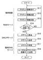
(第2実施形態)
図4は、本発明の第2実施形態に係るネットワークコミュニケーションシステムの一例を示すブロック図である。図2に示すネットワークコミュニケーションシステム2は、データベースサーバ201、RASサーバ202、動的DNSサーバ203、DHCP(Dynamic Host Configuration Protocol)サーバ204、端末装置群10及びHUB20を備えて構成される。すなわち、第2実施形態のネットワークコミュニケーションシステム2は、第1実施形態のネットワークコミュニケーションシステム1にDHCPサーバ204がさらに設けられた構成になっている。
【0038】
データベースサーバ201、RASサーバ202、動的DNSサーバ203、DHCPサーバ204及び端末装置群10は、ローカルエリアネットワークを介して相互に通信可能なように接続されている。なお、第2実施形態におけるデータベースサーバ201、RASサーバ202、動的DNSサーバ203及び端末装置群10は、上記第1実施形態におけるデータベースサーバ101、RASサーバ102、動的DNSサーバ103及び端末装置群10と同様の構成であるので説明を省略する。
【0039】
DHCPサーバ204は、ネットワーク上のノードである端末装置11,12,13,14,15にIPアドレスを自動的に割り当てるサーバ装置であり、HUB20と接続されている。DHCPサーバ204には、自動的に割り当てるIPアドレスの範囲等があらかじめ登録されている。例えば、このIPアドレスの範囲を192.168.0.10〜192.168.0.255とすると、DHCPサーバ204は、アクセスしてきた端末装置に対して192.168.0.10のIPアドレスを自動的に割り当て、次にアクセスしてきた端末装置に対して192.168.0.11のIPアドレスを自動的に割り当てる。DHCPサーバ204には、例えば、192.168.0.4のIPアドレスが割り当てられている。
【0040】
端末装置群10を構成する端末装置11,12,13,14,15にはIPアドレスが割り当てられておらず、DHCPサーバ204によって動的に割り当てられる。
【0041】
図5は、図4に示すネットワークコミュニケーションシステム2の動作の一例を示すフローチャートである。なお、以下の説明では、複数のユーザのうちの一のユーザが端末装置11を用いる場合について説明するが、他のユーザが端末装置11を用いる場合も同様の処理が行われ、一のユーザが端末装置12,13,14,15のいずれかを用いる場合も同様の処理が行われる。
【0042】
図5におけるステップS11からステップS14までの処理は、図2におけるステップS1からステップS4までの処理と同じであるため、説明を省略する。
【0043】
ステップS15において、DHCPサーバ204は、端末装置11に対してIPアドレスを割り当てる。端末装置11に対して割り当てられるIPアドレスは、例えば、192.168.0.10である。
【0044】
ステップS16において、DHCPサーバ204は、端末装置11に割り当てられたIPアドレスと、端末装置11を使用しているユーザのユーザ名とを対応付けて動的DNSサーバ203に送信する。ステップS17において、動的DNSサーバ203は、DHCPサーバ204から送信された端末装置11のIPアドレスと、端末装置11を使用しているユーザのユーザ名とを受信する。
【0045】
図5におけるステップS18の処理は、図2におけるステップS7の処理と同じであるため、説明を省略する。
【0046】
このようにして、ユーザのユーザ名と、ユーザが使用する端末装置11のIPアドレスとが関連付けられるため、従来IPアドレスを指定することで行われていたデータベース間のネットワークコミュニケーションは、動的DNSサーバ203を参照することでユーザ名を指定することで行われる。
【0047】
また、第2実施形態におけるネットワークコミュニケーションシステム2では、第1実施形態のネットワークコミュニケーションシステム1にDHCPサーバ204がさらに設けられているため、IPアドレスを動的に各端末装置に割り当てることができるので、IPアドレスの管理が容易となる。
【0048】
また、所定の範囲内のIP情報であるIPアドレスの中から特定のIPアドレスが端末装置に対して動的に割り当てられるので、あらかじめ各端末装置のIPアドレスを設定する必要がなく、IPアドレスの設定が容易となる。
(第3実施形態)
図6は、本発明の第3実施形態に係るネットワークコミュニケーションシステムの一例を示すブロック図である。図6に示すネットワークコミュニケーションシステム3は、データベースサーバ301、RASサーバ302、動的DNSサーバ303、DHCPサーバ304、LDAP(Lightweight Directory AccessProtocol)サーバ305、端末装置群10及びHUB20を備えて構成される。すなわち、第3実施形態のネットワークコミュニケーションシステム3は、第2実施形態のネットワークコミュニケーションシステム2にLDAPサーバ305がさらに設けられた構成になっている。
【0049】
データベースサーバ301、RASサーバ302、動的DNSサーバ303、DHCPサーバ304、LDAPサーバ305及び端末装置群10は、ローカルエリアネットワークを介して相互に通信可能なように接続されている。なお、第3実施形態におけるデータベースサーバ301、RASサーバ302、動的DNSサーバ303、DHCPサーバ304及び端末装置群10は、上記第2実施形態におけるデータベースサーバ201、RASサーバ202、動的DNSサーバ203、DHCPサーバ204及び端末装置群10と同様の構成であるので説明を省略する。
【0050】
LDAPサーバ305は、ディレクトリサーバであり、LDAPに従い、ユーザ毎のログ情報を管理しているサーバ装置であり、HUB20と接続されている。すなわち、ユーザとIPアドレスとの関係はログインの度に動的に変化するので、LDAPサーバ305は、アクセスログの管理をIPアドレスに基づいて行うのではなく、ユーザ名に基づいて行うことによって、ユーザ毎のログ情報を管理することができる。LDAPサーバ305には、例えば、192.168.0.5のIPアドレスが割り当てられている。LDAPは、ITU−Tが勧告するディレクトリ・サービスの標準規格であるX.500をインターネット上で使用できるように処理を軽くしたプロトコルであるため、LDAPサーバ305を用いてログ情報を管理することで低コスト化を実現することができる。
【0051】
なお、第3実施形態におけるネットワークコミュニケーションシステム3の動作は、図5に示す第2実施形態におけるネットワークコミュニケーションシステム2の動作と同様であるため、説明を省略する。
【0052】
このようにして、ユーザのユーザ名と、ユーザが使用する端末装置11のIPアドレスとが関連付けられるため、従来IPアドレスを指定することで行われていたデータベース間のネットワークコミュニケーションは、動的DNSサーバ303を参照することでユーザ名を指定することで行われる。また、第3実施形態におけるネットワークコミュニケーションシステム3では、第2実施形態のネットワークコミュニケーションシステム2にLDAPサーバ305がさらに設けられているため、従来のようなIPアドレスに基づくログ情報の管理ではなく、ユーザ名に基づくログ情報の管理ができるため、ユーザ毎のログ情報の管理が容易となる。
【0053】
なお、第3実施形態において、LDAPサーバ305が認証サーバの機能を有している場合、RASサーバ302を省略した構成でもよい。この場合、LDAPサーバ305がユーザの使用する端末装置からのアカウント情報を受信し、認証する。
【0054】
なお、本実施形態において、データベースサーバ101,201,301はサービス提供サーバに相当し、RASサーバ102,202,302は認証サーバに相当し、動的DNSサーバ103,203,303はIP情報記憶サーバに相当し、DHCPサーバ204,304は動的IP情報割当サーバに相当し、LDAPサーバ305はディレクトリサーバに相当する。
【0055】
また、本実施形態では、動的DNSサーバ103,203,303は、端末使用者を直接的に特定することができるユーザ名(例えば、ユーザの名前)を含むユーザ情報とIPアドレスとを関連付けて記憶しているが、本発明は特にこれに限定されず、端末使用者を特定することができない匿名性を有する匿名情報とIPアドレスとを関連付けて記憶してもよい。この場合、RASサーバ102,202,302には、ユーザを特定することができるユーザ名を含むユーザ情報とユーザ名を含まない匿名性を有する匿名情報とが対応付けられている。
【0056】
このように、RASサーバ102,202,302には、ユーザを直接的に特定することができるユーザ名を含むユーザ情報と、ユーザ名を含まない匿名情報とが対応付けて記憶されており、動的DNSサーバ103,203,303には、匿名情報とIPアドレスとが関連付けて記憶されているため、ネットワーク通信を行う際にユーザを直接的に特定することができるユーザ名を含むユーザ情報が用いられることがなく、ユーザ名を含まない匿名情報が用いられ、ユーザを特定することができるユーザ情報が外部に公開されにくくなり、セキュリティーを強化することができる。
【0057】
また、ユーザ毎のデータベースをデータベースサーバ101,201,301で一括して管理することができ、データベースサーバ101,201,301のデータベース101d,201d,301dに記憶されている各ユーザのデータを各端末装置11,12,13,14,15に分散させてデータベース11d,12d,13d,14d,15dを構成させることができ、さらに、各端末装置間でデータのレプリケーションを行うことができる。
【0058】
また、本実施形態では、HUB20を用いたスター型のネットワークトポロジとなっているが、本発明は特にこれに限定されず、バス型やリング型等のネットワークトポロジにおいても用いることができる。
【0059】
また、本実施形態では、データベースサーバ101,201,301、RASサーバ102,202,302、動的DNSサーバ103,203,303、DHCPサーバ204,304及びLDAPサーバ305と、端末装置11,12,13,14,15とは、HUB20を介してケーブル等の伝送媒体で接続されているが、本発明は特にこれに限定されず、無線LANを用いてもよい。この場合、データベースサーバ101,201,301、RASサーバ102,202,302、動的DNSサーバ103,203,303、DHCPサーバ204,304及びLDAPサーバ305とHUB20とを接続し、さらにアクセスポイントとHUB20とを接続する。そして、各端末装置11,12,13,14,15には無線LANカードを装着し、相互にデータの送受信を行う。これにより、ユーザは、無線LANの通信範囲内であれば、移動して端末装置を用いることができる。
【0060】
【発明の効果】
以上のように、本発明に係るネットワークコミュニケーションシステムによれば、IP情報記憶サーバに、ユーザを特定するためのユーザ情報と端末装置に割り当てられるIP情報とが関連付けられて記憶されているため、IP情報記憶サーバを参照することで、ユーザ情報から端末装置のIPアドレスを特定することができ、ユーザは特定の端末装置を使用する必要がなくなり、ユーザが端末装置に依存することなくデータの授受を行うことができ、一の端末装置を複数のユーザで共有して使用することができる。
【図面の簡単な説明】
【図1】本発明の第1実施形態に係るネットワークコミュニケーションシステムの一例を示すブロック図である。
【図2】図1に示すネットワークコミュニケーションシステム1の動作の一例を示すフローチャートである。
【図3】端末装置とユーザとの関係を説明するための模式図である。
【図4】本発明の第2実施形態に係るネットワークコミュニケーションシステムの一例を示すブロック図である。
【図5】図2に示すネットワークコミュニケーションシステム2の動作の一例を示すフローチャートである。
【図6】本発明の第3実施形態に係るネットワークコミュニケーションシステムの一例を示すブロック図である。
【図7】従来のネットワークコミュニケーションシステムの一例を示すブロック図である。
【符号の説明】
1,2,3 ネットワークコミュニケーションシステム
101,201,301 データベースサーバ
102,202,302 RASサーバ
103,203,303 動的DNSサーバ
204,304 DHCPサーバ
305 LDAPサーバ
10 端末装置群
11,12,13,14,15 端末装置
20 HUB
A,B ユーザ[0001]
TECHNICAL FIELD OF THE INVENTION
The present invention relates to a network communication system and a network communication method in which a server and a terminal device exchange data in a network.
[0002]
[Prior art]
2. Description of the Related Art Conventionally, a local area network (hereinafter abbreviated as LAN) in which a database server and a plurality of terminal devices are connected has been known (for example, see Patent Document 1). Also, network communication between databases such as replicating a database of one terminal device among a plurality of terminal devices in a LAN to a database of another terminal device is known.
[0003]
FIG. 7 is a block diagram showing an example of a conventional network communication system. The network communication system 4 shown in FIG. 7 includes a
[0004]
In the network communication between the
[0005]
[Patent Document 1]
JP-A-2000-305898
[0006]
[Problems to be solved by the invention]
In the above network communication system 4, an IP address is assigned to each of the
[0007]
The present invention has been made to solve the above problems, and provides a network communication system and a network communication method in which a plurality of users can use one terminal device without depending on the terminal device. It is intended to do so.
[0008]
[Means for Solving the Problems]
A network communication system according to the present invention is a network communication system in which a server and a plurality of terminal devices exchange data in a network, wherein the server includes: a service providing server that provides a service to the terminal device; An authentication server that stores user information for identifying a registered user; and an IP information storage server that can store IP information assigned to the terminal device and the user information in association with each other, The apparatus receives an input of user information for identifying a user, the authentication server authenticates access to the service providing server based on the user information received by the terminal device, and the IP information storage server , For a terminal device authenticated by the authentication server And IP information added, in association with said user information.
[0009]
According to this configuration, first, input of user information for specifying a user is accepted by the terminal device. When the user information received by the terminal device matches the user information registered in advance, the authentication server authenticates access to the service providing server that provides a service to the terminal device. The authentication server associates the user information of the user who uses the terminal device whose access has been authenticated with the IP information and transmits the IP information to the IP information storage server. The IP information storage server stores the IP information assigned to the terminal device whose access has been authenticated by the authentication server and the user information registered in advance in association with each other.
[0010]
That is, since the user information for specifying the user and the IP information assigned to the terminal device are stored in the IP information storage server in association with each other, the terminal device is referred to from the user information by referring to the IP information storage server. The user need not use a specific terminal device. Therefore, the user can exchange data without depending on the terminal device, and one terminal device can be shared and used by a plurality of users.
[0011]
The network communication system further includes a dynamic IP information assignment server that dynamically assigns IP information to the terminal device, wherein the IP information storage server stores the IP assigned by the dynamic IP information assignment server. Preferably, information and the user information are stored in association with each other.
[0012]
According to this configuration, the dynamic IP information allocation server dynamically allocates a specific IP address to the terminal devices from among IP addresses that are IP information within a predetermined range. There is no need to set an IP address, which facilitates setting of the IP address.
[0013]
Preferably, the network communication system further includes a directory server that manages data for each user in a directory and performs a directory service.
[0014]
According to this configuration, since the directory server manages data for each user in a directory and performs a directory service, log information can be managed in association with user information, and log information can be managed in IP address units. Instead of performing log information management, log information can be managed for each user.
[0015]
Further, in the network communication system, the authentication server stores user information including a user name capable of directly specifying a user and anonymous information not including the user name in association with each other. It is preferable that the IP information storage server stores the anonymous information and the IP information in association with each other.
[0016]
According to this configuration, the authentication server stores the user information including the user name capable of directly specifying the user and the anonymous information not including the user name in association with each other. Since the anonymous information and the IP information are stored in association with each other, user information including a user name capable of directly specifying a user when performing network communication is not used, and the user name is not included. The use of anonymous information makes it difficult for user information that can identify a user to be disclosed to the outside, thereby enhancing security.
[0017]
In the network communication system, it is preferable that the service providing server includes a database server, and the terminal device forms a database in the terminal device by receiving data from the database server.
[0018]
According to this configuration, the database for each user can be collectively managed by the database server, and the data of each user stored in the database server can be distributed to a plurality of terminal devices to configure the database. Further, data can be replicated between the terminal devices.
[0019]
A network communication method according to the present invention is a network communication method in which a server and a terminal device exchange data in a network, wherein the server is registered in advance with a service providing server that provides a service to the terminal device. An authentication server that stores user information for specifying the user who has entered, and an IP information storage server that can store the IP information given to the terminal device and the user information in association with each other, wherein the terminal device A first step of receiving an input of user information for specifying a user, and a second step in which the authentication server authenticates access to the service providing server based on the user information received by the terminal device The IP information storage server is authenticated by the authentication server. And IP information assigned to the terminal device which is, and a third step of storing in association with said user information.
[0020]
According to this configuration, in the first step, input of user information for identifying a user is accepted. Then, in the second step, access to a service providing server that provides a service to a plurality of terminal devices is authenticated based on the user information received by the terminal device. The authentication server associates the user information of the user who uses the terminal device whose access has been authenticated with the IP information and transmits the IP information to the IP information storage server. In the third step, IP information assigned to the terminal device authenticated by the authentication server and user information registered in advance are stored in association with each other.
[0021]
That is, since the user information for specifying the user and the IP information assigned to the terminal device are stored in the IP information storage server in association with each other, the terminal device is referred to from the user information by referring to the IP information storage server. The user need not use a specific terminal device. Therefore, the user can exchange data without depending on the terminal device, and one terminal device can be shared and used by a plurality of users.
[0022]
BEST MODE FOR CARRYING OUT THE INVENTION
Hereinafter, embodiments according to the present invention will be described with reference to the drawings.
(1st Embodiment)
FIG. 1 is a block diagram showing an example of the network communication system according to the first embodiment of the present invention. The network communication system 1 illustrated in FIG. 1 includes a
[0023]
In this embodiment, the IP protocol uses version 4 (IPv4), but version 6 (IPv6) may be used.
[0024]
The
[0025]
The
[0026]
The
[0027]
The
[0028]
The
[0029]
In the present embodiment, the
[0030]
FIG. 2 is a flowchart showing an example of the operation of the network communication system 1 shown in FIG. FIG. 3 is a schematic diagram for explaining the relationship between the terminal device and the user. In the following description, a case in which one of a plurality of users uses the
[0031]
In step S1, the
[0032]
In step S2, the
[0033]
In step S4, the
[0034]
In step S5, the
[0035]
In step S7, the
[0036]
In this manner, since the user name of the user and the IP address of the
[0037]
That is, as shown in FIG. 3, when the user A uses the
(2nd Embodiment)
FIG. 4 is a block diagram illustrating an example of the network communication system according to the second embodiment of the present invention. The network communication system 2 illustrated in FIG. 2 includes a
[0038]
The
[0039]
The
[0040]
The
[0041]
FIG. 5 is a flowchart showing an example of the operation of the network communication system 2 shown in FIG. In the following description, a case in which one of a plurality of users uses the
[0042]
The processing from step S11 to step S14 in FIG. 5 is the same as the processing from step S1 to step S4 in FIG.
[0043]
In step S15, the
[0044]
In step S16, the
[0045]
The process in step S18 in FIG. 5 is the same as the process in step S7 in FIG.
[0046]
In this manner, since the user name of the user and the IP address of the
[0047]
In the network communication system 2 according to the second embodiment, since the network communication system 1 according to the first embodiment further includes the
[0048]
Also, since a specific IP address is dynamically assigned to the terminal device from among IP addresses which are IP information within a predetermined range, it is not necessary to set the IP address of each terminal device in advance, and Setting is easy.
(Third embodiment)
FIG. 6 is a block diagram illustrating an example of a network communication system according to the third embodiment of the present invention. The network communication system 3 illustrated in FIG. 6 includes a
[0049]
The
[0050]
The
[0051]
The operation of the network communication system 3 in the third embodiment is the same as the operation of the network communication system 2 in the second embodiment shown in FIG.
[0052]
In this manner, since the user name of the user and the IP address of the
[0053]
In the third embodiment, when the
[0054]
In the present embodiment, the
[0055]
Further, in the present embodiment, the
[0056]
As described above, the
[0057]
In addition, the database for each user can be collectively managed by the
[0058]
Further, in the present embodiment, a star-type network topology using the
[0059]
In the present embodiment, the
[0060]
【The invention's effect】
As described above, according to the network communication system of the present invention, the IP information storage server stores the user information for specifying the user and the IP information assigned to the terminal device in association with each other. By referring to the information storage server, the IP address of the terminal device can be specified from the user information, and the user does not need to use a specific terminal device, and the user can exchange data without depending on the terminal device. This can be performed, and one terminal device can be shared and used by a plurality of users.
[Brief description of the drawings]
FIG. 1 is a block diagram illustrating an example of a network communication system according to a first embodiment of the present invention.
FIG. 2 is a flowchart showing an example of the operation of the network communication system 1 shown in FIG.
FIG. 3 is a schematic diagram for explaining a relationship between a terminal device and a user.
FIG. 4 is a block diagram illustrating an example of a network communication system according to a second embodiment of the present invention.
FIG. 5 is a flowchart showing an example of the operation of the network communication system 2 shown in FIG.
FIG. 6 is a block diagram illustrating an example of a network communication system according to a third embodiment of the present invention.
FIG. 7 is a block diagram illustrating an example of a conventional network communication system.
[Explanation of symbols]
1,2,3 Network communication system
101, 201, 301 Database server
102, 202, 302 RAS server
103, 203, 303 Dynamic DNS server
204, 304 DHCP server
305 LDAP server
10 Terminal device group
11, 12, 13, 14, 15 terminal device
20 HUB
A and B users
Claims (6)
Translated fromJapanese前記サーバは、
前記端末装置にサービスを提供するサービス提供サーバと、
あらかじめ登録されたユーザを特定するためのユーザ情報を記憶する認証サーバと、
前記端末装置に対して付与されるIP情報と前記ユーザ情報とを関連付けて記憶可能なIP情報記憶サーバとを備え、
前記端末装置は、ユーザを特定するためのユーザ情報の入力を受け付け、
前記認証サーバは、前記端末装置によって受け付けられたユーザ情報に基づいて前記サービス提供サーバへのアクセスを認証し、
前記IP情報記憶サーバは、前記認証サーバによって認証された端末装置に対して付与されるIP情報と、前記ユーザ情報とを関連付けて記憶することを特徴とするネットワークコミュニケーションシステム。A network communication system in which a server and a plurality of terminal devices exchange data in a network,
The server comprises:
A service providing server that provides a service to the terminal device;
An authentication server for storing user information for identifying a user registered in advance,
An IP information storage server capable of storing the IP information given to the terminal device and the user information in association with each other,
The terminal device receives an input of user information for identifying a user,
The authentication server authenticates access to the service providing server based on user information received by the terminal device,
The network communication system, wherein the IP information storage server stores IP information assigned to a terminal device authenticated by the authentication server in association with the user information.
前記IP情報記憶サーバは、前記動的IP情報割当サーバによって割り当てられたIP情報と、前記ユーザ情報とを関連付けて記憶することを特徴とする請求項1記載のネットワークコミュニケーションシステム。A dynamic IP information assignment server that dynamically assigns IP information to the terminal device;
2. The network communication system according to claim 1, wherein the IP information storage server stores the IP information assigned by the dynamic IP information assignment server and the user information in association with each other.
前記IP情報記憶サーバは、前記匿名情報と前記IP情報とを関連付けて記憶することを特徴とする請求項1〜3のいずれかに記載のネットワークコミュニケーションシステム。The authentication server stores user information including a user name capable of directly specifying a user and anonymous information not including the user name in association with each other,
The network communication system according to any one of claims 1 to 3, wherein the IP information storage server stores the anonymous information and the IP information in association with each other.
前記端末装置は、前記データベースサーバからのデータを受信することによって前記端末装置内にデータベースを構成することを特徴とする請求項1〜4のいずれかに記載のネットワークコミュニケーションシステム。The service providing server includes a database server,
The network communication system according to any one of claims 1 to 4, wherein the terminal device configures a database in the terminal device by receiving data from the database server.
前記サーバは、
前記端末装置にサービスを提供するサービス提供サーバと、
あらかじめ登録されたユーザを特定するためのユーザ情報を記憶する認証サーバと、
前記端末装置に対して付与されるIP情報と前記ユーザ情報とを関連付けて記憶可能なIP情報記憶サーバとを備え、
前記端末装置が、ユーザを特定するためのユーザ情報の入力を受け付ける第1のステップと、
前記認証サーバが、前記端末装置によって受け付けられたユーザ情報に基づいて前記サービス提供サーバへのアクセスを認証する第2のステップと、
前記IP情報記憶サーバが、前記認証サーバによって認証された端末装置に対して付与されるIP情報と、前記ユーザ情報とを関連付けて記憶する第3のステップとを含むことを特徴とするネットワークコミュニケーション方法。A network communication method in which a server and a terminal device exchange data in a network,
The server comprises:
A service providing server that provides a service to the terminal device;
An authentication server for storing user information for identifying a user registered in advance,
An IP information storage server capable of storing the IP information given to the terminal device and the user information in association with each other,
A first step in which the terminal device receives an input of user information for identifying a user;
A second step in which the authentication server authenticates access to the service providing server based on user information received by the terminal device;
A network communication method comprising: a third step in which the IP information storage server stores the IP information assigned to the terminal device authenticated by the authentication server in association with the user information. .
Priority Applications (1)
| Application Number | Priority Date | Filing Date | Title |
|---|---|---|---|
| JP2002287474AJP2004126785A (en) | 2002-09-30 | 2002-09-30 | Network communication system and network communication method |
Applications Claiming Priority (1)
| Application Number | Priority Date | Filing Date | Title |
|---|---|---|---|
| JP2002287474AJP2004126785A (en) | 2002-09-30 | 2002-09-30 | Network communication system and network communication method |
Publications (1)
| Publication Number | Publication Date |
|---|---|
| JP2004126785Atrue JP2004126785A (en) | 2004-04-22 |
Family
ID=32280268
Family Applications (1)
| Application Number | Title | Priority Date | Filing Date |
|---|---|---|---|
| JP2002287474APendingJP2004126785A (en) | 2002-09-30 | 2002-09-30 | Network communication system and network communication method |
Country Status (1)
| Country | Link |
|---|---|
| JP (1) | JP2004126785A (en) |
Cited By (3)
| Publication number | Priority date | Publication date | Assignee | Title |
|---|---|---|---|---|
| JP2006085578A (en)* | 2004-09-17 | 2006-03-30 | Ricoh Co Ltd | Network device, service usage method, service usage program, and recording medium recording the service usage program |
| US7702694B1 (en) | 2007-09-07 | 2010-04-20 | Southern Company Services, Inc. | System and method for organizing managing and accessing large quantities of data from non-homogenous data sources |
| JP2012198908A (en)* | 2006-11-27 | 2012-10-18 | Qualcomm Inc | Authentication of e-commerce transactions using wireless telecommunications device |
- 2002
- 2002-09-30JPJP2002287474Apatent/JP2004126785A/enactivePending
Cited By (3)
| Publication number | Priority date | Publication date | Assignee | Title |
|---|---|---|---|---|
| JP2006085578A (en)* | 2004-09-17 | 2006-03-30 | Ricoh Co Ltd | Network device, service usage method, service usage program, and recording medium recording the service usage program |
| JP2012198908A (en)* | 2006-11-27 | 2012-10-18 | Qualcomm Inc | Authentication of e-commerce transactions using wireless telecommunications device |
| US7702694B1 (en) | 2007-09-07 | 2010-04-20 | Southern Company Services, Inc. | System and method for organizing managing and accessing large quantities of data from non-homogenous data sources |
Similar Documents
| Publication | Publication Date | Title |
|---|---|---|
| US10135827B2 (en) | Secure access to remote resources over a network | |
| US7706539B2 (en) | Method of guaranteeing users' anonymity and wireless local area network (LAN) system therefor | |
| CN100583874C (en) | Method for creating a peer-to-peer home network using common group label | |
| US8605582B2 (en) | IP network system and its access control method, IP address distributing device, and IP address distributing method | |
| US8312522B2 (en) | Monitoring network traffic by using a monitor device | |
| JP3454931B2 (en) | Network system | |
| US7904712B2 (en) | Service licensing and maintenance for networks | |
| KR101034938B1 (en) | IP6 address and access policy management system and method | |
| US20030229689A1 (en) | Method and system for managing stored data on a computer network | |
| US20030056063A1 (en) | System and method for providing secure access to network logical storage partitions | |
| KR20020036792A (en) | Automated provisioning system | |
| MX2008015235A (en) | Name challenge enabled zones. | |
| KR20040048814A (en) | Method for communication between nodes in peer-to-peer networks using common group label | |
| JP4330342B2 (en) | Packet filtering method and packet communication system for ensuring communication security | |
| US6754212B1 (en) | Repeater and network system utililzing the same | |
| CN114363165A (en) | Configuration method of electronic equipment, electronic equipment and server | |
| JP4835569B2 (en) | Virtual network system and virtual network connection device | |
| CN114884728A (en) | Security access method based on role access control token | |
| JP5187981B2 (en) | Apparatus, method and computer program for allocating network resources | |
| CN101119394A (en) | Network based IP distribution method and bypass equipment | |
| JP2004126785A (en) | Network communication system and network communication method | |
| CA2287788A1 (en) | Method and apparatus providing for internet protocol address authentication | |
| JP2001325172A (en) | Communication setting management system | |
| JP2004030437A (en) | Device and method for managing data and computer program | |
| JP2006295969A (en) | Authentication device and packet communication system for ensuring communication security |
Legal Events
| Date | Code | Title | Description |
|---|---|---|---|
| A621 | Written request for application examination | Free format text:JAPANESE INTERMEDIATE CODE: A621 Effective date:20050927 | |
| A977 | Report on retrieval | Free format text:JAPANESE INTERMEDIATE CODE: A971007 Effective date:20080207 | |
| A131 | Notification of reasons for refusal | Free format text:JAPANESE INTERMEDIATE CODE: A131 Effective date:20080219 | |
| A02 | Decision of refusal | Free format text:JAPANESE INTERMEDIATE CODE: A02 Effective date:20080624 |