JP2004126116A - Designation of location in three-dimensionally displayed electronic map - Google Patents
Designation of location in three-dimensionally displayed electronic mapDownload PDFInfo
- Publication number
- JP2004126116A JP2004126116AJP2002288666AJP2002288666AJP2004126116AJP 2004126116 AJP2004126116 AJP 2004126116AJP 2002288666 AJP2002288666 AJP 2002288666AJP 2002288666 AJP2002288666 AJP 2002288666AJP 2004126116 AJP2004126116 AJP 2004126116A
- Authority
- JP
- Japan
- Prior art keywords
- display
- dimensional
- electronic map
- designated
- virtual space
- Prior art date
- Legal status (The legal status is an assumption and is not a legal conclusion. Google has not performed a legal analysis and makes no representation as to the accuracy of the status listed.)
- Granted
Links
- 238000000034methodMethods0.000claimsdescription38
- 238000004590computer programMethods0.000claimsdescription9
- 238000006243chemical reactionMethods0.000claimsdescription7
- 238000013507mappingMethods0.000claimsdescription5
- 230000004044responseEffects0.000claimsdescription5
- 230000000007visual effectEffects0.000claimsdescription5
- 230000008859changeEffects0.000claimsdescription3
- 238000010586diagramMethods0.000description24
- 230000008569processEffects0.000description16
- 230000004048modificationEffects0.000description14
- 238000012986modificationMethods0.000description14
- 230000015572biosynthetic processEffects0.000description2
- 230000006870functionEffects0.000description2
- 235000004522Pentaglottis sempervirensNutrition0.000description1
- 230000008901benefitEffects0.000description1
- 239000003086colorantSubstances0.000description1
- 230000007423decreaseEffects0.000description1
- 230000000694effectsEffects0.000description1
Images


Landscapes
- Instructional Devices (AREA)
- Processing Or Creating Images (AREA)
Abstract
Description
Translated fromJapanese【0001】
【発明の属する技術分野】
本発明は、3次元的に表示された電子地図における位置の指定に関する。
【0002】
【従来の技術】
従来、コンピュータで利用可能に電子化された、いわゆる電子地図データが普及している。近年では、3次元的な表示が可能な電子地図データも普及している。3次元的に表示された電子地図は、街の鳥瞰や道路の立体交差などを立体的にリアルに表現することができるため、地図の把握がし易いという利点がある。このような3次元的な表示が可能な電子地図データは、いわゆるパーソナルコンピュータにインストールされた地図ソフトや、ナビゲーションシステムなどで利用される。
【0003】
【特許文献1】
特開平4−267427号公報
【特許文献2】
特開平9−265550号公報
【0004】
【発明が解決しようとする課題】
電子地図では、表示画面に表示されるエリアの指定や、ナビゲーションシステムにおける目的地の指定など、ユーザがポインティングデバイスで任意の地点を指定できることが望まれる。しかし、表示画面は2次元であるため、例えば、3次元的に表示された電子地図では、建物の陰になる地点等は、ポインティングデバイスで指定することができなかった。つまり、従来の3次元的に表示された電子地図においては、ポインティングデバイスなどによるオブジェクトや地点の指定方法に支障や制限があった。
【0005】
本発明は、上述の課題を解決するためになされたものであり、3次元的に表示された電子地図において、電子地図上の位置の指定を可能にすることを目的とする。
【0006】
【課題を解決するための手段およびその作用・効果】
上述の課題の少なくとも一部を解決するため、本発明では、以下の構成を採用した。
本発明の第1の地図表示装置は、
所定の電子地図データに基づいて、電子地図を3次元的に表示する地図表示装置であって、
前記電子地図データを参照する参照部と、
前記電子地図データに基づいて定まる3次元の仮想空間を3次元的に表示するための表示画像データを生成し、該表示画像データに基づく表示画像を表示する表示部と、
前記表示画像上で定義された2次元座標系において、ユーザによって指定された指定点に対応する2次元座標値を入力する座標値入力部と、
前記2次元座標値を、前記仮想空間で定義された3次元座標系において、高さが既定値である制約下で、3次元座標値に変換する変換部と、
を備えることを要旨とする。
【0007】
電子地図データは、一般に、緯度、経度などの座標系で、地図上に配置される道路や建物などのオブジェクトの配置位置を示すデータや、オブジェクトの形状データなどを含んでいる。そして、地図表示装置は、このような電子地図データを利用して、3次元の仮想空間を形成し、これを2次元の表示画面上に地図を3次元的に表示することが可能である。3次元の仮想空間は、オブジェクトに現実の高さデータが付与された3次元モデルに基づいて形成してもよいし、2次元の平面モデルにおいて、オブジェクトに任意の高さを付与することによって形成してもよい。ユーザは、地図表示装置の表示画面上で、マウスなどのポインティングデバイスを用いて任意の位置を指定する。
【0008】
本発明では、ユーザによって指定された表示画面上の指定点の2次元座標値を、仮想空間上の3次元座標値へ変換する際に、仮想空間上の3次元座標系における高さを既定値に固定する。このように3次元座標の1つに制約条件をかけることによって、指定点の2次元座標値を3次元座標値に一義的に変換することができる。つまり、3次元的に表示された電子地図において、指定点の電子地図上の位置を一義的に特定することができる。
【0009】
本発明の第1の地図表示装置において、
前記既定値は、例えば、予め設定された所定値であるものとすることができる。
【0010】
「所定値」は、任意に設定可能であり、例えば、地表面の代表高さなど、所定の標高とすることができる。本発明によって、指定点の2次元座標値を、仮想空間内において高さが所定値の3次元座標値に変換することができる。
【0011】
また、本発明の第1の地図表示装置において、
前記既定値は、例えば、前記仮想空間内の地表面に基づいた高さであるものとしてもよい。
【0012】
「地表面に基づいた高さ」とは、例えば、地表面高さであってもよいし、地表面から一定の高さであってもよい。こうすることによって、地表に起伏がある場合でも、指定点の2次元座標値を仮想空間内の地表面上の3次元座標値に変換することができる。
【0013】
上記地図表示装置において、例えば、
前記表示部が、前記仮想空間内に設定された視点および視野枠に基づいて前記表示画像データを生成する場合、
前記変換部は、前記2次元座標値を、前記2次元座標値を前記視野枠に写像して得られる点と、前記視点とを結ぶ直線が、前記仮想空間内の地表面と交差する点の3次元座標値に変換するようにすることができる。
【0014】
こうすることによって、例えば、仮想空間内で地表面が起伏している場合でも、表示画面上の指定点を仮想空間上の3次元座標値に変換し、位置を特定することができる。
【0015】
上述した本発明の第1の地図表示装置において、
前記表示部は、前記仮想空間内に設定された視線ベクトルに基づいて前記表示画像データを生成し、
前記変換部は、前記視線ベクトルと直交する前記仮想空間内の地表面上の軸よりも、前記表示画像において上側の点が前記指定点として指定されているときに、前記2次元座標値を、前記指定点から前記軸への垂線の足に対応する3次元座標値に変換するようにすることができる。
【0016】
3次元的な地図を2次元的な表示画面上に表示する場合、視点に近い領域を表す表示画面の下側よりも、視点から遠い位置を表す表示画面の上側の方が、仮想空間における奥行き方向の座標間隔が狭く表示されるため、ユーザは、表示画面上で位置の指定を行いにくくなる傾向にある。このため、ユーザが意図した指定点と特定結果との誤差が大きくなる場合がある。
【0017】
本発明では、前記軸を境界線として、2次元座標値から3次元座標値への座標値の変換方法、即ち、指定点の特定方法を切り換える。表示画面において、指定点が、視点から遠い、前記軸よりも上側の領域に存在する場合は、ユーザが軸上の点を指定したものとして指定点の2次元座標値を取り扱う。こうすることによって、ユーザの意図と大きく離れた地点が特定されることを回避することができる。
【0018】
本発明の第2の地図表示装置は、
所定の電子地図データに基づいて、電子地図を3次元的に表示する地図表示装置であって、
前記電子地図データを参照する参照部と、
前記電子地図データに基づいて、該電子地図データに含まれる少なくとも一部のオブジェクトを立体オブジェクトとして立体的に表示することにより、前記電子地図データに基づいて定まる3次元の仮想空間を3次元的に表示するための表示画像データを生成し、該表示画像データに基づく表示画像を表示する表示部と、
前記表示画面上で定義された2次元座標系において、ユーザによって指定された指定点に対応する2次元座標値を入力する座標値入力部と、
前記2次元座標値に基づいて、前記指定点に、前記立体オブジェクトの表示画像が存在するか否かを判断する判断部と、
該判断部が、前記立体オブジェクトの表示画像が存在すると判断した場合に、該立体オブジェクトを、前記ユーザが指定する指定オブジェクトとして特定する特定部と、
を備えることを要旨とする。
【0019】
3次元的に表示される電子地図上に配置されるオブジェクトには、ビルなど立体的に表示される立体オブジェクトと、地表面上に沿って通る道路など平面的に表示される平面オブジェクトとがある。本発明では、ユーザが表示画面上で立体オブジェクトの画像を指定したときに、仮想空間上においても、そのオブジェクトが指定されたものとして特定することができる。
【0020】
上記地図表示装置において、更に、
前記特定部は、前記仮想空間において、前記指定オブジェクトに対応づけられた所定の代表点の3次元座標を出力するようにすることができる。
【0021】
電子地図データにおいて、オブジェクトは、通常、その配置位置である代表点と対応付けられている。本発明によって、ユーザによって表示画面上で立体オブジェクトの画像のどの部分(2次元座標値)が指定されても、代表点が指定されたものとして指定点の3次元座標値を特定することができる。
【0022】
上記地図表示装置において、代表点として、例えば、ビルの屋上など、オブジェクトによって異なった、高さを含む3次元座標値を用いるようにしてもよいが、
前記代表点は、前記指定オブジェクトに含まれ、前記仮想空間内の地表面上の一点であるものとすることができる。
【0023】
こうすることによって、複数の立体オブジェクトについて、3次元座標値のうちの高さを統一することができるので、仮想空間における位置の特定を容易に行うことができる。
【0024】
本発明の第2の地図表示装置において、
前記表示部は、前記指定オブジェクトを強調表示するようにすることができる。
【0025】
こうすることによって、ユーザは、自らが表示画面上で指定した立体オブジェクトが地図表示装置によって有効に取り扱われていることを視認することができる。
【0026】
本発明の第2の地図表示装置において、
前記表示部は、少なくとも、前記表示画像上で前記指定オブジェクトの少なくとも一部を遮る立体オブジェクトを半透明表示、あるいは、透明表示するようにしてもよい。
【0027】
こうすることによって、表示画面上に指定オブジェクトの全体像を表示することができるので、ユーザが指定オブジェクトを見易くすることができる。
【0028】
上述した指定オブジェクトを強調表示する、あるいは、指定オブジェクトの少なくとも一部を遮る立体オブジェクトを半透明表示する地図表示装置において、
前記電子地図データは、前記立体オブジェクトと対応付けられ、該立体オブジェクトに関する所定の付加情報を含んでいる場合、
前記地図表示装置は、更に、
前記指定オブジェクトの前記付加情報の表示要求を入力する要求入力部を備え、
前記表示部は、前記表示要求に応じて、更に、前記付加情報を表示するようにすることができる。
【0029】
こうすることによって、ユーザは、指定オブジェクトに対応する付加情報を利用することができ、電子地図の利便性を向上させることができる。
【0030】
本発明の第2の地図表示装置において、更に、
前記指定オブジェクトを半透明表示する指示を入力する指示入力部を備え、
前記表示部は、前記指示に応じて、前記指定オブジェクトを半透明表示するようにしてもよい。また、前記指定オブジェクトを透明表示する指示を入力する指示入力部を備え、前記表示部は、前記指示に応じて、前記指定オブジェクトを透明表示するようにしてもよい。
【0031】
こうすることによって、ユーザの指示によって、指定オブジェクトを半透明表示させることができる。この場合、半透明に表示された指定オブジェクトは、地図上にないものとして取り扱う。この結果、指定オブジェクトの陰に隠れていたオブジェクトを、更に、指定オブジェクトとして指定することができる。
【0032】
上述した本発明の第2の地図表示装置において、
前記表示部は、前記仮想空間内に設定された視線ベクトルに基づいて前記表示画像データを生成し、
更に、前記視線ベクトルと直交する前記仮想空間内の地表面上の軸よりも、前記表示画像において上側の点が前記指定点として指定されているときに、前記2次元座標値を、前記指定点から前記軸への垂線の足に対応する3次元座標値に変換する変換部を備えるようにしてもよい。
【0033】
こうすることによって、先に第1の地図表示装置で説明したのと同様に、指定点の特定を簡易に行うことができる。
【0034】
本発明の第1または第2の地図表示装置において、
前記表示部は、前記指定点の周辺領域を表す2次元の電子地図を、前記3次元的に表示された電子地図と共に表示するようにしてもよい。
【0035】
こうすることによって、ユーザは、指定点の周辺領域の地図を、3次元的な表示と、2次元的な表示との双方で、同時に同じ表示画面で見ることができるので、電子地図の利便性を向上させることができる。更に、3次元的な表示と同時に表示された2次元的に表示された地図において、2次元的な位置の指定を行えるようにしてもよい。
【0036】
なお、上記地図表示装置において、
前記表示部は、前記指定点の周辺領域については、前記3次元的な表示に代えて、前記2次元の電子地図を表示するようにしてもよい。
【0037】
本発明は、画像データ生成装置の発明として構成することもできる。即ち、本発明の画像データ生成装置は、
所定の電子地図データに基づいて、所定の表示装置に電子地図を表示させるための表示画像データを生成する画像データ生成装置であって、
前記電子地図データを参照する参照部と、
前記電子地図データに基づいて定まる3次元の仮想空間を表示するための表示画像データを、該仮想空間内に設定された視点および視線ベクトルに基づいて、該視線ベクトルと前記仮想空間内の地表面とのなす角度および前記視点が、表示対象となる前記仮想空間の領域に応じて、相対的に異なるように生成する表示画像データ生成部と、
を備えることを要旨とする。
【0038】
「視線ベクトルと仮想空間内の地表面とのなす角度および視点が、表示対象となる仮想空間の領域に応じて、相対的に異なる」とは、仮想空間の座標値を固定して、視線ベクトルを変化させてもよいし、視線ベクトルを固定して、仮想空間の座標値を変化させてもよいことを意味している。本発明によって、地図表示装置に、様々な視線から仮想空間の地表面を見たときの地図を表示させることができる。
【0039】
なお、上記画像データ生成装置において、
前記表示画像データ生成部は、前記視線ベクトルと前記地表面とのなす角度および視線を単調に変化させることによって、前記表示画像が3次元的な表示から2次元表示に連続的に変化する表示画像データを生成するようにしてもよい。
【0040】
本発明の画像データ生成装置で生成された表示画像データは、地図表示装置の表示画面に表示される。従って、上述した画像データ生成装置と、生成された表示画像データに基づく表示画像を表示する表示部とを備える地図表示装置の発明として構成することもできる。
【0041】
また、表示画面に表示された地図を印刷装置によって印刷して利用することも可能であり、地図の発明として構成することもできる。
【0042】
本発明は、上述の地図表示装置、画像データ生成装置としての構成の他、電子地図においてユーザが指定した指定点やオブジェクトの特定方法、電子地図を表示させるための画像データ生成方法、電子地図の表示方法の発明として構成することもできる。また、これらを実現するコンピュータプログラム、およびそのプログラムを記録した記録媒体、そのプログラムを含み搬送波内に具現化されたデータ信号など種々の態様で実現することが可能である。なお、それぞれの態様において、先に示した種々の付加的要素を適用することが可能である。
【0043】
本発明をコンピュータプログラムまたはそのプログラムを記録した記録媒体等として構成する場合には、地図表示装置を駆動するプログラム全体として構成するものとしてもよいし、本発明の機能を果たす部分のみを構成するものとしてもよい。また、記録媒体としては、フレキシブルディスクやCD−ROM、DVD−ROM、光磁気ディスク、ICカード、ROMカートリッジ、パンチカード、バーコードなどの符号が印刷された印刷物、コンピュータの内部記憶装置(RAMやROMなどのメモリ)および外部記憶装置などコンピュータが読み取り可能な種々の媒体を利用できる。
【0044】
【発明の実施の形態】
以下、本発明の実施の形態について、実施例に基づき以下の順序で説明する。
A.第1実施例:
A1.地図表示装置の概略構成:
A2.3D地図表示処理:
A3.指定点特定処理:
A4.サブディスプレイ表示処理:
A5.付加情報表示処理:
B.第2実施例:
C.変形例:
【0045】
A.第1実施例:
A1.地図表示装置の概略構成:
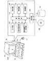
図1は、第1実施例としての地図表示装置10の概略構成を示す説明図である。本実施例の地図表示装置10は、汎用のパーソナルコンピュータであり、図示しないCPUやメモリの他、マウス12や、表示画面DSPを表示するためのディスプレイ14や、ハードディスク16や、CD−ROMドライブ18などを備えている。地図表示装置10は、パーソナルコンピュータに、電子地図を表示するためのアプリケーションプログラムをインストールすることによって構成されている。
【0046】
地図表示装置10は、図示した各機能ブロックをソフトウェア的に備えている。制御部110は、地図表示装置10内の各部の動作制御を行う。参照部120は、電子地図データを記録したコンパクト・ディスクCDや、ハードディスク16から電子地図データを参照する。電子地図データは、地図上の位置を示す緯度、経度や、地図上に配置されるオブジェクトの配置位置を示すデータや、オブジェクト(地物)の形状データや高さデータや、オブジェクトに関する付加情報などを含んでいる。付加情報としては、ビルの名称や、店舗の電話番号、営業時間など、ユーザに提供するための情報が挙げられる。参照部120は、電子地図データを、インターネットなどのネットワークを介して所定のサーバから参照するようにしてもよい。
【0047】
表示画像データ生成部130は、参照部120が参照した電子地図データに基づいて、更に、後述する入力部150に入力された各種指示等に応じて、ディスプレイ14に、2次元表示(2D)の電子地図を表示したり、3次元的な表示(3D)の電子地図を表示したりするための画像データを生成する。表示画像データ生成部130は、更に、後述するように、ユーザからの指示に応じて、表示画面DSPに表示された3D地図上に立体的に表示されたビルなどの立体オブジェクトの表示方法を変更したり、ユーザによって指定されたオブジェクトに対応する付加情報を表示させたりするための表示画像データを生成したりもする。表示制御部140は、表示画像データ生成部130で生成された画像データをディスプレイ14に表示するための制御を行う。
【0048】
入力部150は、ディスプレイ14の表示画面DSPの切り換え等のユーザからの各種指示の入力や、表示画面DSP上で、ユーザによってマウス12を用いて指定された指定点の2次元座標値を入力する。判断部160は、指定点の2次元座標値に基づいて、表示画面DSPに表示された立体オブジェクトの画像と指定点との位置関係などを判断する。この判断の詳細については、後述する。特定部170は、判断部160が、指定点が立体オブジェクトの画像上に存在すると判断したときに、その立体オブジェクトを、ユーザによって指定された指定オブジェクトとして特定する。更に、特定部170は、指定オブジェクトの代表点の3次元座標値を出力する。代表点とは、電子地図上に配置されるオブジェクトに対応付けられた代表的な配置位置の座標値である。本実施例では、代表点は、地表面上の点であるものとした。変換部180は、指定点の2次元座標値を、判断部160の判断結果に応じて、3次元座標値に変換する。
【0049】
A2.3D地図表示処理:
図2は、3D地図表示処理の流れを示すフローチャートである。地図表示装置10のCPUが実行する処理である。まず、CPUは、入力部150によって、ユーザによって指定された表示エリアを取得する(ステップS100)。表示エリアとしては、例えば、「九州」、「福岡県」、「北九州市」、更に、町名、番地などの住所が挙げられる。次に、表示エリアに基づいて、参照部120によって、電子地図データを参照する(ステップS110)。そして、表示画像データ生成部130によって、2次元表示の電子地図を表示するための2D表示画像データを生成し(ステップS120)、表示画面DSPに2D地図を表示する(ステップS130)。次に、入力部150によって、ユーザが2D地図上で指定したエリアについての3D地図の表示指示を取得する(ステップS140)。そして、参照部120によって、電子地図データを参照し、表示画像データ生成部130によって、3次元的な表示の電子地図を表示するための3D表示画像データを生成して(ステップS150)、表示画面DSPに3D地図を表示する(ステップS160)。このとき、表示画面DSPには、2次元座標上で移動するマウスポインタも表示される。なお、本実施例では、2D地図を表示した後に、3D地図を表示するものとしたが、2D地図の表示処理(ステップS120、および、ステップS13)をジャンプしてもよい。
【0050】
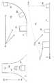
図3は、3D表示画像データの生成方法について示す説明図である。図の右側には、電子地図データに基づいて定まる3次元の仮想空間VSを示した。仮想空間VSの地表面Gには、表示画面DSPに立体オブジェクトとして表示されるビルBLDが配置されている。図の左側には、表示画面DSPを示した。表示画面DSPには、仮想空間VSにおけるビルBLDを立体的に表示した立体オブジェクトとしてのビルbldの画像が配置されている。
【0051】
本実施例では、仮想空間VS内に視点PV、視点PVからの視線ベクトル、および、視野枠FRMを設定し、視点PVから視野枠FRMを通して仮想空間VSの地表面Gを見たときの像を用いて3D表示画像データを生成するものとした。視野枠FRMと視点PVとの距離を変更することによって、あるいは、視野枠FRMのサイズを変更することによって、表示画面DSPに表示される地図の縮尺を変更することができる。なお、視野枠FRMから見える仮想空間VSの地表面Gには、図示した例では、X軸に平行な軸AXが設定されている。軸AXは、地表面G上で視線ベクトルに直交する軸である。この軸AXは、表示画面DSPの軸axと対応している。
【0052】
A3.指定点特定処理:
本実施例の地図表示装置10は、3D地図が表示された表示画面DSP上において、マウス12を用いてユーザによって指定された指定点の仮想空間VS内の位置を特定することができる。指定点の位置の特定は、以下に説明する3通りに分けて行う。即ち、(1)指定点が表示画面DSPの軸axよりも上側の領域に存在する場合、(2)指定点が表示画面DSPの軸axよりも下側の領域に存在し、その点に立体オブジェクトの画像が存在しない場合、(3)指定点が表示画面DSPの軸axよりも下側の領域に存在し、その点に立体オブジェクトの画像が存在する場合、の3通りである。
【0053】
図3に(1)、(2)の場合の指定点の特定方法を併せて示した。図3において、点Paは、表示画面DSPの軸axよりも上側の領域に存在する点である。この場合、点Paから軸axへの垂線の足である点Pa’を求め、点Pa’を視野枠FRMに写像して得られる点Pa’mと視点PVとを結ぶ直線が仮想空間VSの地表面Gと交差する軸AX上の点Pavを仮想空間VS内の指定点として特定する。
【0054】
3D地図を表示する場合、視点PVに近い領域を表す表示画面DSPの下側よりも、視点PVから遠い位置を表す表示画面DSPの上側の方が、仮想空間における奥行き方向の座標間隔が狭く表示されるため、ユーザは、表示画面上で位置の指定を行いにくくなる傾向にある。このため、ユーザが意図した指定点と特定結果との誤差が大きくなる場合がある。先に説明したように、軸axよりも上側の指定点を軸ax上の点として取り扱うことによって、仮想空間VSにおいて、ユーザの意図と大きく離れた地点が特定されることを回避することができる。なお、軸axを考慮せずに、次に説明する(2)、(3)の場合と同様に指定点の特定を行ってもよい。
【0055】
図3において、点Pbは、表示画面DSPの軸axよりも下側の領域に存在し、その点に立体オブジェクトの画像が存在しない点である。この場合、点Pbを視野枠FRMに写像して得られる点Pbmと視点PVとを結ぶ直線が仮想空間VSの地表面Gと交差する点Pbvを仮想空間VS内の指定点として特定する。
【0056】
こうすることによって、例えば、仮想空間VS内で地表面Gが起伏している場合でも、表示画面DSP上の指定点を仮想空間VS上の3次元座標値に変換し、位置を特定することができる。
【0057】
図4は、(3)の場合の仮想空間VSにおける指定点の特定方法を示す説明図である。立体オブジェクトの画像上に表した点P1〜P4は、いずれも図3に示した軸axよりも下側の領域に存在する点であるものとする。この場合、表示画面DSPにおいて、指定点として点P1〜P4のいずれが指定されたとしても、代表点Prが指定されたものとして取り扱う。即ち、代表点Prを視野枠FRMに写像して得られる点と視点PVとを結ぶ直線が仮想空間VSの地表面Gと交差する点を仮想空間VS内の指定点として特定する。
【0058】
こうすることによって、ユーザが表示画面DSPで立体オブジェクトを指定したときに、仮想空間VS上においても、そのオブジェクトが指定されたものとして特定し、更に、3次元座標値を特定することができる。
【0059】
図5は、指定点特定処理の流れを示すフローチャートである。地図表示装置10のCPUが実行する処理である。まず、CPUは、入力部150によって、表示画面DSPにおける指定点の2次元座標値を取得する(ステップS200)。次に、判断部160によって、指定点が表示画面DSP上の軸axよりも上側の領域に存在するか否かを判断する(ステップS210)。指定点が軸axよりも上側の領域に存在する場合は、先に説明したように、仮想空間VS内の地表面G上に設定された軸AX上の3次元座標値に変換する(ステップS220)。
【0060】
ステップS210において、指定点が軸axよりも下側の領域に存在する場合は、指定点に立体オブジェクトの画像が存在するか否かを判断する(ステップS230)。指定点に立体オブジェクトの画像が存在しない場合には、先に説明したように、仮想空間VS内の地表面G上の3次元座標値に変換する(ステップS240)。
【0061】
本実施例の地図表示装置10は、表示画面DSPにおいて、指定点に立体オブジェクトの画像が存在する場合、ユーザの指示によって、その立体オブジェクト(指定オブジェクト)を半透明表示させることができる。
【0062】
図6は、指定オブジェクトを半透明表示させる様子を示す説明図である。ここでは、表示画面DSPに4つのビルBLD1〜BLD4が表示されている例を示した。図6(a)に示したように、ユーザがマウス12によってビルBLD4を指定し、半透明表示させる指示を入力する。そうすると、図6(b)に示したように、ビルBLD4が半透明表示され、ビルBLD4の陰に隠れていたビルBLD1〜BLD3の一部や、道路が表示される。これらの表示画像データは、先に説明したように、表示画像データ生成部130が生成する。
【0063】
こうすることによって、指定オブジェクトの陰に隠れていた他の立体オブジェクトや地表面を表示させることができる。このとき、半透明表示された指定オブジェクトは、地図上にないものとして取り扱われる。従って、ユーザは、半透明表示された領域において、新たに指定点を指定することができる。
【0064】
図5のステップS230において、指定点に立体オブジェクトの画像が存在する場合には、ユーザから半透明表示の指示があるか否かを判断する(ステップS250)。半透明表示の指示がある場合には、指定点に存在する立体オブジェクトを半透明表示する(ステップS260)。そして、次の指定点の2次元座標値を取得し(ステップS265)、ステップS230に戻る。
【0065】
ステップS250において、半透明表示の指示がない場合には、表示画面DSP上で、指定オブジェクトの少なくとも一部を遮っている立体オブジェクトが存在するか否かを判断する(ステップS270)。指定オブジェクトの少なくとも一部を遮っている立体オブジェクトが存在しない場合には、先に説明したように、指定オブジェクトの代表点Prに対応する仮想空間VS内の点の3次元座標値を出力する(ステップS290)。指定オブジェクトの少なくとも一部を遮っている立体オブジェクトが存在する場合には、遮る立体オブジェクトを半透明表示して(ステップS280)、指定オブジェクトの代表点Prに対応する仮想空間VS内の点の3次元座標値を出力する(ステップS290)。
【0066】
図7は、指定オブジェクトの少なくとも一部を遮る立体オブジェクトを半透明表示させる様子を示す説明図である。表示画面DSPに4つのビルBLD1〜BLD4が表示されている例を示した。図7(a)に示したように、ユーザがマウス12によってビルBLD1指定する。図示した例では、ビルBLD2〜BLD4がビルBLD1の一部を遮っているので、図6(b)に示したように、ビルBLD2〜BLD4を半透明に表示する。これらの表示画像データは、表示画像データ生成部130が生成する。
【0067】
こうすることによって、表示画面DSP上に指定オブジェクトの全体像を表示することができるので、ユーザは、自らが指定した指定オブジェクトが地図表示装置10によって有効に取り扱われていることを視認するとともに、指定オブジェクトを見易くすることができる。
【0068】
A4.サブディスプレイ表示処理:
本実施例の地図表示装置10は、指定点の周辺領域について、表示画面DSPに表示された3D地図の中にサブディスプレイ領域を形成し、この領域に2D地図を表示させることができる。
【0069】
図8は、サブディスプレイ表示処理の流れを示す説明図である。指定点の特定後に、地図表示装置10のCPUが実行する処理である。まず。CPUは、入力部150によって、ユーザからのサブディスプレイ表示の指示を取得する(ステップS300)。次に、参照部120によって、電子地図データを参照する(ステップS310)。次に、表示画像データ生成部130によって、指定点の周辺領域の2D表示画像データを生成する(ステップS320)。そして、サブディスプレイの形成位置を指定点付近に設定して、表示画面DSPに表示中の3D地図の3D表示画像データとステップS320で生成した2D表示画像データとを合成し(ステップS330)、合成地図を表示画面DSPに表示する(ステップS340)。
【0070】
図9は、サブディスプレイSDSPの表示例を示す説明図である。図9(a)に示したように、表示画面DSP上でユーザがマウス12によって任意の指定点を指定する。そうすると、先に説明した指定点特定処理によって、仮想空間VS上の点の3次元座標値が特定される。そして、図8に示した処理によって、図9(b)に示したように、表示画面DSP内に、指定点の周辺領域を示す2D地図を表示するサブディスプレイSDSPが表示される。このとき、マウスポインタは、図示するように、サブディスプレイSDSP上で移動する。
【0071】
こうすることによって、ユーザは、指定点の周辺領域の地図を、3次元的な表示と、2次元的な表示との双方で、同時に同じ表示画面DSPで見ることができるので、電子地図の利便性を向上させることができる。更に、3次元的な表示と同時に表示された2次元的に表示された地図において、2次元的な位置の指定を行えるようにしてもよい。
【0072】
A5.付加情報表示処理:
本実施例の地図表示装置10は、ユーザの指示によって、3D電子地図データが含む付加情報を表示画面DSPに表示させることも可能である。
【0073】
図10は、付加情報表示処理の流れを示すフローチャートである。指定点の特定後に、地図表示装置10のCPUが実行する処理である。まず、CPUは、入力部150によって、ユーザからの付加情報の表示指示を取得する(ステップS400)。次に、参照部120によって、電子地図データを参照し(ステップS410)、指定オブジェクトに対応する付加情報を表示画面DSPに表示する(ステップS420)。
【0074】
図11は、付加情報の表示例を示す説明図である。ここでは、ユーザがビルBLD1の付加情報の表示指示を入力した場合について示した。図示するように、指定オブジェクトとしてのビルBLD1の画像とともに、その付加情報が表示される。
【0075】
こうすることによって、3D地図においても、ユーザは、指定オブジェクトに対応する付加情報を利用することができ、電子地図の利便性を向上させることができる。
【0076】
B.第2実施例:
第1実施例では、地図表示装置10は、仮想空間VSにおいて視点PVを固定して、表示画面DSPに3次元的に一様に表示するための表示画像データを生成した。第2実施例では、仮想空間VSが3次元的な表示から2次元表示に連続的に変化する表示画像データを生成し、表示画面DSPに表示する。第2実施例の地図表示装置の構成は、第1実施例の地図表示装置と同様であるので、説明を省略する。
【0077】
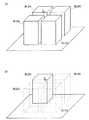
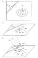
図12は、第2実施例の地図表示装置10における表示画像データの生成方法、および、表示画像の一例を示す説明図である。図12の右側には、表示画像データの生成方法を概念的に示した。右図下段に図示した例では、3次元的な仮想空間VSの地表面Gに3つの建物B1、B2、B3が配置されている様子を示している。ここでは、仮想空間VSの領域に応じて、異なる視点PV1、PV2、PV3、および、視線ベクトルが設定されており、視線ベクトルと仮想空間VSの地表面Gとのなす角度を、仮想空間VSの奥行き方向(Y軸方向)に、単調に増加させて、表示画像データを生成する様子を示している。視線ベクトルと地表面Gとのなす角度は相対的なものであるから、右図上段に図示したように、視点を点PV’に固定し、湾曲した地表面G’の法線方向に建物B1’、B2’、B3’を配置した仮想空間VS’を形成して表示画像データを生成するのと同等である。このようにして生成した表示画像データに基づく表示画像を左図に示した。図示した建物b1、b2、b3の様子から、表示画像が3次元的な表示から2次元表示に連続的に変化している様子が分かる。
【0078】
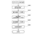
図13は、第2実施例における地図表示処理の流れを示すフローチャートである。地図表示装置10のCPUが実行する処理である。まず、CPUは、入力部150によって、ユーザによって指定された表示エリアを取得する(ステップS500)。次に、表示エリアに基づいて、参照部120によって、電子地図データを参照する(ステップS510)。次に、表示画像データ生成部130によって、図12に示した地表面が湾曲した仮想空間VS’を定義し(ステップS520)、平面オブジェクトおよび立体オブジェクトを配置する(ステップS540)。立体オブジェクトは、それぞれ高さデータに基づいて、地表面から垂直方向に配置される。次に、視点PV’および視野枠FRMを設定する(ステップS540)。そして、先に説明した表示画像データを生成し(ステップS550)、表示画面DSPに地図を表示する(ステップS560)。
【0079】
このように表示画像データを生成することによって、様々な視点から地表面を見た仮想空間の地図を表示することができる。また、本実施例では、仮想空間VSの奥の方の領域において、視線ベクトルと地表面Gとのなす角度が大きいため、奥の方の領域が2次元表示に近い状態で表示される。従って、表示画面上でユーザが位置の指定を行いやすいという利点もある。本実施例の地図表示装置10で表示された地図は、印刷装置で印刷して利用することも可能である。
【0080】
なお、第2実施例の地図表示装置の構成は、第1実施例の地図表示装置10と同様であるから、第2実施例の地図表示装置においても、地図表示装置10と同様にして、指定点特定処理や、サブディスプレイ表示処理や、付加情報表示処理などの処理を行うことができる。
【0081】
C.変形例:
以上、本発明のいくつかの実施の形態について説明したが、本発明はこのような実施の形態になんら限定されるものではなく、その要旨を逸脱しない範囲内において種々なる態様での実施が可能である。例えば、以下のような変形例が可能である。
【0082】
C1.変形例1:
上記第1実施例では、図5〜図7を用いて説明した指定点特定処理のステップS270において、指定オブジェクトを遮る立体オブジェクトを半透明表示するものとしたが、これに限られない。この場合において、例えば、指定オブジェクトを強調表示するようにしてもよい。図14は、変形例としての指定オブジェクトを強調表示した様子を示す説明図である。強調表示としては、例えば、色彩や模様を変化させた表示などが挙げられる。このようにすることによっても、表示画面DSP上に指定オブジェクトの全体像を表示することができるので、ユーザは、自らが指定した指定オブジェクトが地図表示装置10によって有効に取り扱われていることを視認するとともに、指定オブジェクトを見易くすることができる。
【0083】
C2.変形例2:
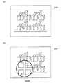
上記第1実施例では、マウスポインタは、表示画面DSPの2次元座標上で移動するものとしたが、仮想空間VS内の3次元座標上で移動するマウスポインタを表示するものとしてもよい。図15は、本変形例におけるマウスポインタの移動の様子を示す説明図である。図15(a)は、2D地図を示している。図中の楕円は、等高線であり、山が存在していることを示している。図15(b)、(c)は、3D地図を示している。図15(b)、(c)中には、マウスポインタが視点から遠ざかるに連れて、徐々に小さくなっていく様子も併せて示した。
【0084】
図15(b)は、図15(a)に示した地点A〜Dまでマウスポインタが地表面上に沿って移動する様子を示している。図示するように地点Aおよび地点Dでは、マウスポインタMPa、MPdは、山の陰に隠れておらず、視点から見える。地点Bおよび地点Cでは、マウスポインタMPb、MPcは、破線で示したように、山の陰に隠れてしまうので、視点から見えない。なお、このようにマウスポインタがオブジェクトの陰に隠れる場合には、オブジェクトの陰の領域が見えるように、視点を変更した3D地図を表示してもよい。また、マウスポインタが見えるように、第1実施例で説明したサブディスプレイの表示を行うようにしてもよい。こうすることによって、ユーザが指定したい地点を3D地図上に表示することができる。
【0085】
図15(b)に示したマウスポインタの表示は、以下の処理によって行う。地図表示装置は、過去に移動したマウスポインタの2次元座標値およびこれに対応する仮想空間の3次元座標値の履歴データを保持する履歴データ保持部を備えている。地図表示装置のCPUは、現在のマウスポインタの2次元座標値と履歴データの2次元座標値とを取得し、両者からマウスポインタの移動方向および移動量を算出する。そして、算出した移動方向、移動量、および、履歴データの3次元座標値に基づいて、地図上にマウスポインタの表示を行う。このような処理によって、図15(b)に示した、マウスポインタが地表面に沿って山を登り、下ってゆく様子を表示することができる。
【0086】
図15(c)は、マウスポインタが仮想空間の空中を移動する様子を示している。本変形例では、マウスポインタが仮想空間内の所定の高さを移動するように設定される。また、仮想空間内の所定位置に太陽sunが設定される。図中に黒で示した矢印SPa、SPdは、マウスポインタMPa、MPdの影である。マウスポインタMPb、マウスポインタMPcの影SPb、SPcは、山の陰に隠れていて見えない。このように、空中を移動するマウスポインタMPa〜MPdおよびその影SPa、SPdの表示を行い、影の地点をマウスポインタが指している地点としてもよい。こうすることによって、マウスポインタがオブジェクトの陰に隠れてしまうことを回避することができる。
【0087】
C3.変形例3:
上記第1実施例では、指定点特定処理において、指定点が表示画面DSPの軸axよりも上側の領域に存在するか否かの判断を行ったが、この判断を行わなくてもよい。この場合、指定点に立体オブジェクトの画像が存在するか否かに応じて、位置の特定方法を切り換えればよい。
【0088】
更に、指定点に立体オブジェクトが存在するか否かの判断も行わなくてもよい。この場合、例えば、指定点が常に地表面上の地点を指定しているものとして、位置の特定を行えばよい。
【0089】
C4.変形例4:
上記第1実施例では、指定点特定処理において、指定点の2次元座標値を仮想空間VSにおける地表面G上の3次元座標値に変換したが、これに限られない。高さは、既定値を用いることが可能であり、例えば、所定の標高など、予め設定された所定値を用いることが可能である。
【0090】
C5.変形例5:
上記第1実施例では、サブディスプレイ表示処理において、サブディスプレイSDSPの形成位置を指定点付近に設定し、図9(b)に示したように、指定点周辺を3次元的な表示に代えて、2次元表示で表示したが、これに限られない。例えば、両者を並べて表示するようにしてもよい。
【0091】
C6.変形例6:
上記第1実施例では、付加情報表示処理において、指定オブジェクトに対応付けられた付加情報を表示するものとしたが、更に、指定オブジェクト内の位置を指定可能とし、その位置に対応付けられた付加情報を表示するようにしてもよい。例えば、高層ビルの各階を指定して、各付加情報を表示できるようにしてもよい。
【0092】
C7.変形例7:
上記第2実施例では、視線ベクトルと地表面とのなす角度を、仮想空間の奥行き方向(Y方向)に、単調に増加させて表示画像データを生成したが、これに限られない。例えば、幅方向(X方向)に変化させてもよい。また、変化のさせ方は、単調な変化に限らず、任意に変化させてもよい。
【0093】
C8.変形例8:
上記実施例では、地図表示装置10は、パーソナルコンピュータに、電子地図を表示するためのアプリケーションプログラムをインストールすることによって構成されているものとしたが、例えば、カーナビゲーション装置などの地図表示装置に本発明を適用するものとしてもよい。
【0094】
また、図1に示した機能ブロックの一部を、ネットワークを介して接続されたサーバに備えるようにしてもよい。例えば、サーバ側で電子地図データを参照し、表示画像データの生成を行うようにしてもよい。
【図面の簡単な説明】
【図1】第1実施例としての地図表示装置10の概略構成を示す説明図である。
【図2】3D地図表示処理の流れを示すフローチャートである。
【図3】3D表示画像データの生成方法について示す説明図である。
【図4】指定点が表示画面DSPの軸axよりも下側の領域に存在し、その点に立体オブジェクトの画像が存在する場合の、仮想空間VSにおける指定点の特定方法を示す説明図である。
【図5】指定点特定処理の流れを示すフローチャートである。
【図6】指定オブジェクトを半透明表示させる様子を示す説明図である。
【図7】指定オブジェクトの少なくとも一部を遮る立体オブジェクトを半透明表示させる様子を示す説明図である。
【図8】サブディスプレイ表示処理の流れを示す説明図である。
【図9】サブディスプレイSDSPの表示例を示す説明図である。
【図10】付加情報表示処理の流れを示すフローチャートである。
【図11】付加情報の表示例を示す説明図である。
【図12】第2実施例の地図表示装置10における表示画像データの生成方法、および、表示画像の一例を示す説明図である。
【図13】第2実施例における地図表示処理の流れを示すフローチャートである。
【図14】変形例としての指定オブジェクトを強調表示した様子を示す説明図である。
【図15】変形例におけるマウスポインタの移動の様子を示す説明図である。
【符号の説明】
10…地図表示装置
12…マウス
14…ディスプレイ
16…ハードディスク
18…CD−ROMドライブ
110…制御部
120…参照部
130…表示画像データ生成部
140…表示制御部
150…入力部
160…判断部
170…特定部
180…変換部
DSP…表示画面
VS、VS’…仮想空間
G、G’、g…地表面
PV、PV1〜PV3、PV’…視点
FRM…視野枠
AX、ax…軸
Pr…代表点
SDSP…サブディスプレイ[0001]
TECHNICAL FIELD OF THE INVENTION
The present invention relates to designation of a position on a three-dimensionally displayed electronic map.
[0002]
[Prior art]
2. Description of the Related Art Conventionally, so-called electronic map data digitized so as to be usable by a computer has been widely used. In recent years, electronic map data that can be displayed three-dimensionally has become widespread. The three-dimensionally displayed electronic map has a merit that the map can be easily grasped because a bird's eye view of a city, a three-dimensional intersection of a road, and the like can be realistically represented in three dimensions. Such electronic map data capable of three-dimensional display is used in map software installed in a so-called personal computer, a navigation system, and the like.
[0003]
[Patent Document 1]
JP-A-4-267427
[Patent Document 2]
JP-A-9-265550
[0004]
[Problems to be solved by the invention]
In an electronic map, it is desired that a user can designate an arbitrary point with a pointing device, such as designation of an area displayed on a display screen or designation of a destination in a navigation system. However, since the display screen is two-dimensional, for example, in an electronic map displayed three-dimensionally, it is not possible to specify a point or the like behind a building with a pointing device. That is, in the conventional three-dimensionally displayed electronic map, there is an obstacle or limitation in a method of specifying an object or a point using a pointing device or the like.
[0005]
The present invention has been made to solve the above-described problem, and has as its object to enable a position on an electronic map to be specified in an electronic map displayed three-dimensionally.
[0006]
[Means for Solving the Problems and Their Functions and Effects]
In order to solve at least a part of the problems described above, the present invention employs the following configurations.
A first map display device according to the present invention includes:
A map display device for displaying an electronic map three-dimensionally based on predetermined electronic map data,
A reference unit that refers to the electronic map data;
A display unit that generates display image data for three-dimensionally displaying a three-dimensional virtual space determined based on the electronic map data, and displays a display image based on the display image data;
A coordinate value input unit for inputting a two-dimensional coordinate value corresponding to a designated point designated by a user in a two-dimensional coordinate system defined on the display image;
A conversion unit that converts the two-dimensional coordinate value into a three-dimensional coordinate value in a three-dimensional coordinate system defined in the virtual space under a constraint that a height is a default value;
The gist is to provide
[0007]
The electronic map data generally includes data indicating an arrangement position of an object such as a road or a building arranged on a map in a coordinate system such as latitude and longitude, and shape data of the object. The map display device can form a three-dimensional virtual space using such electronic map data, and can display the map three-dimensionally on a two-dimensional display screen. The three-dimensional virtual space may be formed based on a three-dimensional model in which real height data is added to an object, or may be formed by giving an arbitrary height to an object in a two-dimensional plane model. May be. The user specifies an arbitrary position on the display screen of the map display device using a pointing device such as a mouse.
[0008]
According to the present invention, when converting a two-dimensional coordinate value of a specified point on a display screen specified by a user into a three-dimensional coordinate value in a virtual space, the height in the three-dimensional coordinate system in the virtual space is set to a predetermined value. Fixed to. Thus, by applying a constraint condition to one of the three-dimensional coordinates, the two-dimensional coordinate value of the designated point can be uniquely converted to a three-dimensional coordinate value. That is, in the electronic map displayed three-dimensionally, the position of the designated point on the electronic map can be uniquely specified.
[0009]
In the first map display device of the present invention,
The predetermined value may be, for example, a predetermined value set in advance.
[0010]
The “predetermined value” can be set arbitrarily, and can be, for example, a predetermined altitude such as a representative height of the ground surface. According to the present invention, a two-dimensional coordinate value of a designated point can be converted into a three-dimensional coordinate value having a predetermined height in a virtual space.
[0011]
Further, in the first map display device of the present invention,
The predetermined value may be, for example, a height based on the ground surface in the virtual space.
[0012]
The “height based on the ground surface” may be, for example, the ground surface height or a constant height from the ground surface. In this way, even when the ground surface has undulations, the two-dimensional coordinate values of the designated point can be converted to three-dimensional coordinate values on the ground surface in the virtual space.
[0013]
In the above map display device, for example,
When the display unit generates the display image data based on a viewpoint and a view frame set in the virtual space,
The conversion unit may be configured to convert the two-dimensional coordinate value into a point obtained by mapping the two-dimensional coordinate value on the visual field frame and a point at which a straight line connecting the viewpoint intersects a ground surface in the virtual space. It can be converted to three-dimensional coordinate values.
[0014]
By doing so, for example, even when the ground surface is undulating in the virtual space, the designated point on the display screen can be converted into a three-dimensional coordinate value in the virtual space, and the position can be specified.
[0015]
In the first map display device of the present invention described above,
The display unit generates the display image data based on a line-of-sight vector set in the virtual space,
The conversion unit, when an upper point in the display image is specified as the specified point than an axis on the ground surface in the virtual space orthogonal to the line of sight vector, the two-dimensional coordinate value, The coordinate may be converted into a three-dimensional coordinate value corresponding to a foot perpendicular to the axis from the designated point.
[0016]
When displaying a three-dimensional map on a two-dimensional display screen, the depth in the virtual space is larger in the upper part of the display screen representing a position far from the viewpoint than in the lower part of the display screen representing an area close to the viewpoint. Since the coordinate interval in the direction is displayed narrow, it tends to be difficult for the user to specify the position on the display screen. For this reason, the error between the specified point intended by the user and the specified result may be large.
[0017]
In the present invention, a method of converting a coordinate value from a two-dimensional coordinate value to a three-dimensional coordinate value, that is, a method of specifying a designated point is switched using the axis as a boundary line. On the display screen, when the specified point is located in a region far from the viewpoint and above the axis, the two-dimensional coordinate value of the specified point is handled as if the user specified a point on the axis. By doing so, it is possible to prevent a point far from the user's intention from being specified.
[0018]
The second map display device of the present invention comprises:
A map display device for displaying an electronic map three-dimensionally based on predetermined electronic map data,
A reference unit that refers to the electronic map data;
Based on the electronic map data, at least a part of the objects included in the electronic map data is displayed as a three-dimensional object three-dimensionally, so that a three-dimensional virtual space determined based on the electronic map data is three-dimensionally displayed. A display unit that generates display image data for display and displays a display image based on the display image data;
A coordinate value input unit for inputting a two-dimensional coordinate value corresponding to a designated point designated by a user in a two-dimensional coordinate system defined on the display screen;
A determining unit configured to determine whether a display image of the three-dimensional object is present at the designated point based on the two-dimensional coordinate value;
A determining unit that, when the determining unit determines that a display image of the three-dimensional object is present, specifies the three-dimensional object as a specified object specified by the user;
The gist is to provide
[0019]
The objects arranged on the three-dimensionally displayed electronic map include a three-dimensional object such as a building and a three-dimensional object and a two-dimensional object such as a road running along the ground surface. . According to the present invention, when a user specifies an image of a three-dimensional object on a display screen, the object can be specified as specified in the virtual space.
[0020]
In the above map display device,
The specifying unit may output three-dimensional coordinates of a predetermined representative point associated with the specified object in the virtual space.
[0021]
In the electronic map data, an object is usually associated with a representative point which is an arrangement position thereof. According to the present invention, no matter what part (two-dimensional coordinate value) of the image of the three-dimensional object is specified on the display screen by the user, the three-dimensional coordinate value of the specified point can be specified as the representative point is specified. .
[0022]
In the above-described map display device, as the representative point, for example, a three-dimensional coordinate value including a height, which differs depending on the object, such as the roof of a building, may be used.
The representative point may be included in the designated object and may be a point on the ground surface in the virtual space.
[0023]
This makes it possible to unify the heights of the three-dimensional coordinate values for the plurality of three-dimensional objects, so that the position in the virtual space can be easily specified.
[0024]
In the second map display device of the present invention,
The display unit may highlight the designated object.
[0025]
By doing so, the user can visually recognize that the three-dimensional object specified by the user on the display screen is being effectively handled by the map display device.
[0026]
In the second map display device of the present invention,
The display unit may display at least a three-dimensional object that blocks at least a part of the designated object on the display image in a translucent or transparent manner.
[0027]
By doing so, the entire image of the designated object can be displayed on the display screen, so that the user can easily see the designated object.
[0028]
In the map display device for highlighting the specified object described above, or for translucently displaying a three-dimensional object that blocks at least a part of the specified object,
When the electronic map data is associated with the three-dimensional object and includes predetermined additional information regarding the three-dimensional object,
The map display device further comprises:
A request input unit for inputting a display request for the additional information of the designated object,
The display unit may further display the additional information in response to the display request.
[0029]
By doing so, the user can use the additional information corresponding to the designated object, and can improve the convenience of the electronic map.
[0030]
In the second map display device of the present invention,
An instruction input unit for inputting an instruction to translucently display the designated object,
The display unit may display the designated object translucently in response to the instruction. Further, an instruction input unit for inputting an instruction to transparently display the designated object may be provided, and the display unit may transparently display the designated object in response to the instruction.
[0031]
By doing so, the designated object can be displayed translucently by the user's instruction. In this case, the translucent designated object is treated as not being on the map. As a result, the object hidden behind the designated object can be further designated as the designated object.
[0032]
In the above-described second map display device of the present invention,
The display unit generates the display image data based on a line-of-sight vector set in the virtual space,
Furthermore, when a point above the axis on the ground surface in the virtual space that is orthogonal to the line-of-sight vector is specified in the display image as the specified point, the two-dimensional coordinate value is changed to the specified point. And a conversion unit for converting into a three-dimensional coordinate value corresponding to a foot of a perpendicular to the axis.
[0033]
By doing so, it is possible to easily specify the designated point in the same manner as described in the first map display device.
[0034]
In the first or second map display device of the present invention,
The display unit may display a two-dimensional electronic map representing an area around the designated point together with the three-dimensionally displayed electronic map.
[0035]
By doing so, the user can simultaneously view the map of the area around the designated point on the same display screen in both the three-dimensional display and the two-dimensional display. Can be improved. Further, a two-dimensional position may be designated on a two-dimensionally displayed map displayed simultaneously with the three-dimensional display.
[0036]
In the above map display device,
The display unit may display the two-dimensional electronic map instead of the three-dimensional display in the area around the designated point.
[0037]
The present invention can be configured as an invention of an image data generation device. That is, the image data generation device of the present invention
An image data generation device that generates display image data for displaying an electronic map on a predetermined display device based on predetermined electronic map data,
A reference unit that refers to the electronic map data;
Display image data for displaying a three-dimensional virtual space determined based on the electronic map data, based on a viewpoint and a line of sight vector set in the virtual space, the line of sight vector and the ground surface in the virtual space. A display image data generation unit that generates the angle and the viewpoint formed with each other according to the region of the virtual space to be displayed, so as to be relatively different from each other;
The gist is to provide
[0038]
"The angle and viewpoint formed between the line-of-sight vector and the ground surface in the virtual space are relatively different depending on the region of the virtual space to be displayed" means that the coordinate value of the virtual space is fixed and the line-of-sight vector is fixed. May be changed, or the line-of-sight vector may be fixed, and the coordinate values of the virtual space may be changed. According to the present invention, it is possible to cause a map display device to display a map when the ground surface of the virtual space is viewed from various lines of sight.
[0039]
In the above image data generation device,
The display image data generating unit is configured to monotonously change an angle between the line-of-sight vector and the ground surface and a line of sight, so that the display image continuously changes from a three-dimensional display to a two-dimensional display. Data may be generated.
[0040]
The display image data generated by the image data generation device of the present invention is displayed on the display screen of the map display device. Therefore, the invention can be configured as an invention of a map display device including the above-described image data generation device and a display unit that displays a display image based on the generated display image data.
[0041]
Further, the map displayed on the display screen can be printed and used by a printing device, and can be configured as a map invention.
[0042]
The present invention provides, in addition to the configurations as the above-described map display device and image data generating device, a method for specifying a designated point or an object specified by a user on an electronic map, an image data generating method for displaying an electronic map, and an electronic map. The invention may be configured as a display method invention. Further, the present invention can be realized in various forms such as a computer program for realizing the above, a recording medium on which the program is recorded, and a data signal including the program and embodied in a carrier wave. In each embodiment, the various additional elements described above can be applied.
[0043]
When the present invention is configured as a computer program or a recording medium on which the program is recorded, the present invention may be configured as an entire program for driving a map display device, or may be configured only as a portion that performs the functions of the present invention. It may be. Examples of the recording medium include a flexible disk, a CD-ROM, a DVD-ROM, a magneto-optical disk, an IC card, a ROM cartridge, a punched card, a printed matter on which a code such as a barcode is printed, and an internal storage device (RAM, Various computer-readable media such as a memory such as a ROM) and an external storage device can be used.
[0044]
BEST MODE FOR CARRYING OUT THE INVENTION
Hereinafter, embodiments of the present invention will be described in the following order based on examples.
A. First embodiment:
A1. Schematic configuration of map display device:
A2.3 3D map display processing:
A3. Designated point identification processing:
A4. Sub-display processing:
A5. Additional information display processing:
B. Second embodiment:
C. Modification:
[0045]
A. First embodiment:
A1. Schematic configuration of map display device:
FIG. 1 is an explanatory diagram showing a schematic configuration of a
[0046]
The
[0047]
The display image
[0048]
The
[0049]
A2.3 3D map display processing:
FIG. 2 is a flowchart showing the flow of the 3D map display process. This is a process executed by the CPU of the
[0050]
FIG. 3 is an explanatory diagram showing a method of generating 3D display image data. The right side of the figure shows a three-dimensional virtual space VS determined based on the electronic map data. On the ground surface G of the virtual space VS, a building BLD displayed as a three-dimensional object on the display screen DSP is arranged. The display screen DSP is shown on the left side of the figure. On the display screen DSP, an image of a building bld as a three-dimensional object that three-dimensionally displays the building BLD in the virtual space VS is arranged.
[0051]
In the present embodiment, a viewpoint PV, a line-of-sight vector from the viewpoint PV, and a visual field frame FRM are set in the virtual space VS, and an image when the ground surface G of the virtual space VS is viewed from the viewpoint PV through the visual field frame FRM is displayed. To generate 3D display image data. The scale of the map displayed on the display screen DSP can be changed by changing the distance between the view frame FRM and the viewpoint PV, or by changing the size of the view frame FRM. Note that, in the illustrated example, an axis AX parallel to the X axis is set on the ground surface G of the virtual space VS viewed from the viewing frame FRM. The axis AX is an axis orthogonal to the line-of-sight vector on the ground surface G. This axis AX corresponds to the axis ax of the display screen DSP.
[0052]
A3. Designated point identification processing:
The
[0053]
FIG. 3 also shows a method of specifying a designated point in the cases (1) and (2). In FIG. 3, a point Pa is a point existing in a region above the axis ax of the display screen DSP. In this case, a point Pa ′, which is a foot of a perpendicular from the point Pa to the axis ax, is obtained, and a straight line connecting the point Pa′m obtained by mapping the point Pa ′ on the field of view frame FRM and the viewpoint PV is a virtual space VS. A point Pav on the axis AX intersecting with the ground surface G is specified as a designated point in the virtual space VS.
[0054]
When displaying a 3D map, the coordinate space in the depth direction in the virtual space is displayed narrower on the upper side of the display screen DSP representing a position far from the viewpoint PV than on the lower side of the display screen DSP representing an area close to the viewpoint PV. Therefore, it tends to be difficult for the user to specify the position on the display screen. For this reason, the error between the specified point intended by the user and the specified result may be large. As described above, by treating the specified point above the axis ax as a point on the axis ax, it is possible to avoid specifying a point that is far from the user's intention in the virtual space VS. . The specified point may be specified without considering the axis ax in the same manner as in the following cases (2) and (3).
[0055]
In FIG. 3, a point Pb exists in a region below the axis ax of the display screen DSP, and is a point at which no image of the three-dimensional object exists. In this case, a point Pbv at which a straight line connecting the point Pbm obtained by mapping the point Pb to the field frame FRM and the viewpoint PV intersects the ground surface G of the virtual space VS is specified as a designated point in the virtual space VS.
[0056]
By doing so, for example, even when the ground surface G is undulating in the virtual space VS, the designated point on the display screen DSP can be converted into three-dimensional coordinate values on the virtual space VS to specify the position. it can.
[0057]
FIG. 4 is an explanatory diagram showing a method for specifying a designated point in the virtual space VS in the case of (3). Points P1 to P4 represented on the image of the three-dimensional object are all points existing in an area below the axis ax shown in FIG. In this case, no matter which of the points P1 to P4 is designated as the designated point on the display screen DSP, the representative point Pr is handled as being designated. That is, the point at which the straight line connecting the point obtained by mapping the representative point Pr to the visual field frame FRM and the viewpoint PV intersects the ground surface G of the virtual space VS is specified as the designated point in the virtual space VS.
[0058]
By doing so, when the user specifies a three-dimensional object on the display screen DSP, the object can be specified as specified on the virtual space VS, and further three-dimensional coordinate values can be specified.
[0059]
FIG. 5 is a flowchart showing the flow of the designated point specifying process. This is a process executed by the CPU of the
[0060]
In step S210, when the specified point is located in the area below the axis ax, it is determined whether or not an image of the three-dimensional object exists at the specified point (step S230). If there is no image of the three-dimensional object at the designated point, as described above, the image is converted into three-dimensional coordinate values on the ground surface G in the virtual space VS (step S240).
[0061]
When an image of a three-dimensional object is present at a specified point on the display screen DSP, the
[0062]
FIG. 6 is an explanatory diagram illustrating a state in which the designated object is displayed in a translucent manner. Here, an example is shown in which four buildings BLD1 to BLD4 are displayed on the display screen DSP. As shown in FIG. 6A, the user designates the building BLD4 with the
[0063]
By doing so, other three-dimensional objects or the ground surface hidden behind the designated object can be displayed. At this time, the designated object that is displayed translucently is treated as not being on the map. Therefore, the user can designate a new designated point in the translucently displayed area.
[0064]
If the image of the three-dimensional object is present at the designated point in step S230 in FIG. 5, it is determined whether or not there is an instruction for translucent display from the user (step S250). If there is a translucent display instruction, the three-dimensional object existing at the designated point is translucently displayed (step S260). Then, the two-dimensional coordinate value of the next designated point is obtained (step S265), and the process returns to step S230.
[0065]
If there is no instruction for translucent display in step S250, it is determined whether or not a three-dimensional object that blocks at least a part of the designated object exists on the display screen DSP (step S270). When there is no three-dimensional object that blocks at least a part of the designated object, as described above, the three-dimensional coordinate value of the point in the virtual space VS corresponding to the representative point Pr of the designated object is output ( Step S290). If there is a three-dimensional object that blocks at least a part of the designated object, the three-dimensional object to be blocked is translucently displayed (step S280), and three points in the virtual space VS corresponding to the representative point Pr of the designated object are displayed. The dimensional coordinate values are output (step S290).
[0066]
FIG. 7 is an explanatory diagram showing a state in which a three-dimensional object that blocks at least a part of the designated object is displayed translucently. An example is shown in which four buildings BLD1 to BLD4 are displayed on the display screen DSP. As shown in FIG. 7A, the user designates the building BLD1 with the
[0067]
By doing so, the entire image of the specified object can be displayed on the display screen DSP, so that the user visually recognizes that the specified object specified by the user is being effectively handled by the
[0068]
A4. Sub-display processing:
The
[0069]
FIG. 8 is an explanatory diagram showing the flow of the sub-display processing. This processing is executed by the CPU of the
[0070]
FIG. 9 is an explanatory diagram showing a display example of the sub-display SDSP. As shown in FIG. 9A, the user designates an arbitrary designated point with the
[0071]
By doing so, the user can simultaneously view the map of the area around the designated point on the same display screen DSP in both the three-dimensional display and the two-dimensional display. Performance can be improved. Further, a two-dimensional position may be designated on a two-dimensionally displayed map displayed simultaneously with the three-dimensional display.
[0072]
A5. Additional information display processing:
The
[0073]
FIG. 10 is a flowchart illustrating the flow of the additional information display process. This processing is executed by the CPU of the
[0074]
FIG. 11 is an explanatory diagram illustrating a display example of additional information. Here, a case where the user inputs a display instruction of additional information of building BLD1 is shown. As shown in the figure, the additional information is displayed together with the image of the building BLD1 as the designated object.
[0075]
By doing so, the user can use the additional information corresponding to the designated object also in the 3D map, and the convenience of the electronic map can be improved.
[0076]
B. Second embodiment:
In the first embodiment, the
[0077]
FIG. 12 is a diagram illustrating a method of generating display image data in the
[0078]
FIG. 13 is a flowchart showing the flow of the map display process in the second embodiment. This is a process executed by the CPU of the
[0079]
By generating the display image data in this manner, it is possible to display a map of a virtual space in which the ground surface is viewed from various viewpoints. Further, in the present embodiment, since the angle between the line-of-sight vector and the ground surface G is large in the region at the back of the virtual space VS, the region at the back is displayed in a state close to two-dimensional display. Therefore, there is also an advantage that the user can easily specify the position on the display screen. The map displayed on the
[0080]
Since the configuration of the map display device of the second embodiment is the same as that of the
[0081]
C. Modification:
As described above, several embodiments of the present invention have been described. However, the present invention is not limited to such embodiments at all, and can be implemented in various modes without departing from the gist thereof. It is. For example, the following modifications are possible.
[0082]
C1. Modification 1
In the first embodiment, in step S270 of the designated point specifying process described with reference to FIGS. 5 to 7, the three-dimensional object that blocks the designated object is displayed translucently. However, the present invention is not limited to this. In this case, for example, the designated object may be highlighted. FIG. 14 is an explanatory diagram showing a state in which a designated object as a modification is highlighted. Examples of the highlighted display include a display in which colors and patterns are changed. By doing so, the entire image of the designated object can be displayed on the display screen DSP, so that the user visually recognizes that the designated object designated by the user is being effectively handled by the
[0083]
C2. Modified example 2:
In the first embodiment, the mouse pointer moves on the two-dimensional coordinates of the display screen DSP. However, the mouse pointer may move on three-dimensional coordinates in the virtual space VS. FIG. 15 is an explanatory diagram showing how the mouse pointer moves in this modification. FIG. 15A shows a 2D map. The ellipse in the figure is a contour line, indicating that a mountain exists. FIGS. 15B and
[0084]
FIG. 15B shows how the mouse pointer moves along the ground surface to points A to D shown in FIG. As shown in the figure, at the points A and D, the mouse pointers MPa and MPd are not hidden behind a mountain but can be seen from the viewpoint. At the points B and C, the mouse pointers MPb and MPc are hidden behind a mountain, as indicated by the broken lines, and cannot be seen from the viewpoint. When the mouse pointer is hidden behind the object, a 3D map whose viewpoint has been changed may be displayed so that the shadow area of the object can be seen. Further, the sub-display described in the first embodiment may be displayed so that the mouse pointer can be seen. By doing so, the point that the user wants to specify can be displayed on the 3D map.
[0085]
The display of the mouse pointer shown in FIG. 15B is performed by the following processing. The map display device includes a history data holding unit that holds history data of two-dimensional coordinate values of a mouse pointer that has moved in the past and corresponding three-dimensional coordinate values of a virtual space. The CPU of the map display device obtains the current two-dimensional coordinate value of the mouse pointer and the two-dimensional coordinate value of the history data, and calculates the moving direction and the moving amount of the mouse pointer from both. Then, the mouse pointer is displayed on the map based on the calculated moving direction, the moving amount, and the three-dimensional coordinate value of the history data. By such processing, it is possible to display a state in which the mouse pointer climbs the mountain along the ground surface and descends as shown in FIG.
[0086]
FIG. 15C shows a state where the mouse pointer moves in the air in the virtual space. In this modification, the mouse pointer is set to move at a predetermined height in the virtual space. The sun sun is set at a predetermined position in the virtual space. Arrows SPa and SPd shown in black in the figure are shadows of the mouse pointers MPa and MPd. The mouse pointer MPb and the shadows SPb and SPc of the mouse pointer MPc are hidden behind a mountain and cannot be seen. In this manner, the mouse pointers MPa to MPd moving in the air and their shadows SPa and SPd are displayed, and the point of the shadow may be the point pointed by the mouse pointer. By doing so, it is possible to prevent the mouse pointer from being hidden behind the object.
[0087]
C3. Modification 3:
In the first embodiment, in the specified point specifying process, it is determined whether or not the specified point exists in the area above the axis ax of the display screen DSP, but this determination may not be performed. In this case, the position specifying method may be switched depending on whether or not the image of the three-dimensional object exists at the designated point.
[0088]
Further, it is not necessary to determine whether or not the three-dimensional object exists at the designated point. In this case, for example, the position may be specified assuming that the specified point always specifies a point on the ground surface.
[0089]
C4. Modification 4:
In the first embodiment, in the designated point specifying process, the two-dimensional coordinate value of the designated point is converted into the three-dimensional coordinate value on the ground surface G in the virtual space VS. However, the present invention is not limited to this. For the height, a predetermined value can be used, and for example, a predetermined value such as a predetermined altitude can be used.
[0090]
C5. Modification 5:
In the first embodiment, in the sub-display processing, the formation position of the sub-display SDSP is set near the designated point, and as shown in FIG. Although the two-dimensional display is used, the present invention is not limited to this. For example, both may be displayed side by side.
[0091]
C6. Modification 6:
In the first embodiment, in the additional information display processing, the additional information associated with the designated object is displayed. However, a position in the designated object can be designated, and the additional information associated with the position can be designated. Information may be displayed. For example, each additional information may be displayed by specifying each floor of a high-rise building.
[0092]
C7. Modification 7:
In the second embodiment, the display image data is generated by monotonically increasing the angle between the line-of-sight vector and the ground surface in the depth direction (Y direction) of the virtual space, but is not limited thereto. For example, it may be changed in the width direction (X direction). In addition, the way of changing is not limited to a monotonous change and may be changed arbitrarily.
[0093]
C8. Modification 8:
In the above embodiment, the
[0094]
Further, a part of the functional blocks shown in FIG. 1 may be provided in a server connected via a network. For example, the server may refer to the electronic map data to generate the display image data.
[Brief description of the drawings]
FIG. 1 is an explanatory diagram showing a schematic configuration of a
FIG. 2 is a flowchart illustrating a flow of a 3D map display process.
FIG. 3 is an explanatory diagram illustrating a method of generating 3D display image data.
FIG. 4 is an explanatory diagram showing a method for specifying a designated point in the virtual space VS when a designated point exists in an area below the axis ax of the display screen DSP and an image of a three-dimensional object exists at that point. is there.
FIG. 5 is a flowchart illustrating a flow of a designated point specifying process.
FIG. 6 is an explanatory diagram showing a state in which a designated object is displayed translucently.
FIG. 7 is an explanatory diagram showing a state in which a three-dimensional object that blocks at least a part of a designated object is displayed translucently.
FIG. 8 is an explanatory diagram showing a flow of sub-display processing.
FIG. 9 is an explanatory diagram showing a display example of a sub-display SDSP.
FIG. 10 is a flowchart illustrating a flow of an additional information display process.
FIG. 11 is an explanatory diagram showing a display example of additional information.
FIG. 12 is a diagram illustrating a method of generating display image data in a
FIG. 13 is a flowchart illustrating a flow of a map display process according to the second embodiment.
FIG. 14 is an explanatory diagram showing a state in which a designated object as a modification is highlighted.
FIG. 15 is an explanatory diagram showing how a mouse pointer moves in a modified example.
[Explanation of symbols]
10. Map display device
12 ... Mouse
14 ... Display
16 ... Hard disk
18 CD-ROM drive
110 ... Control unit
120 ... Reference section
130: Display image data generation unit
140 ... Display control unit
150 ... input unit
160 ... Judgment unit
170 ... Specific part
180 ... Converter
DSP… Display screen
VS, VS '... virtual space
G, G ', g ... ground surface
PV, PV1 to PV3, PV '... viewpoint
FRM: Field of view frame
AX, ax ... axis
Pr: representative point
SDSP… Sub-display
Claims (22)
Translated fromJapanese前記電子地図データを参照する参照部と、
前記電子地図データに基づいて定まる3次元の仮想空間を3次元的に表示するための表示画像データを生成し、該表示画像データに基づく表示画像を表示する表示部と、
前記表示画像上で定義された2次元座標系において、ユーザによって指定された指定点に対応する2次元座標値を入力する座標値入力部と、
前記2次元座標値を、前記仮想空間で定義された3次元座標系において、高さが既定値である制約下で、3次元座標値に変換する変換部と、
を備える地図表示装置。A map display device for displaying an electronic map three-dimensionally based on predetermined electronic map data,
A reference unit that refers to the electronic map data;
A display unit that generates display image data for three-dimensionally displaying a three-dimensional virtual space determined based on the electronic map data, and displays a display image based on the display image data;
A coordinate value input unit for inputting a two-dimensional coordinate value corresponding to a designated point designated by a user in a two-dimensional coordinate system defined on the display image;
A conversion unit that converts the two-dimensional coordinate value into a three-dimensional coordinate value in a three-dimensional coordinate system defined in the virtual space under a constraint that a height is a default value;
A map display device comprising:
前記既定値は、予め設定された所定値である、地図表示装置。The map display device according to claim 1,
The map display device, wherein the predetermined value is a predetermined value set in advance.
前記既定値は、前記仮想空間内の地表面に基づいた高さである、地図表示装置。The map display device according to claim 1,
The map display device, wherein the predetermined value is a height based on a ground surface in the virtual space.
前記表示部は、前記仮想空間内に設定された視点および視野枠に基づいて前記表示画像データを生成し、
前記変換部は、前記2次元座標値を、前記2次元座標値を前記視野枠に写像して得られる点と、前記視点とを結ぶ直線が、前記仮想空間内の地表面と交差する点の3次元座標値に変換する、
地図表示装置。The map display device according to claim 3, wherein
The display unit generates the display image data based on a viewpoint and a field of view set in the virtual space,
The conversion unit is configured to convert the two-dimensional coordinate value into a point obtained by mapping the two-dimensional coordinate value onto the visual field frame and a point at which a straight line connecting the viewpoint intersects a ground surface in the virtual space. Convert to three-dimensional coordinates,
Map display device.
前記電子地図データを参照する参照部と、
前記電子地図データに基づいて、該電子地図データに含まれる少なくとも一部のオブジェクトを立体オブジェクトとして立体的に表示することにより、前記電子地図データに基づいて定まる3次元の仮想空間を3次元的に表示するための表示画像データを生成し、該表示画像データに基づく表示画像を表示する表示部と、
前記表示画面上で定義された2次元座標系において、ユーザによって指定された指定点に対応する2次元座標値を入力する座標値入力部と、
前記2次元座標値に基づいて、前記指定点に、前記立体オブジェクトの表示画像が存在するか否かを判断する判断部と、
該判断部が、前記立体オブジェクトの表示画像が存在すると判断した場合に、該立体オブジェクトを、前記ユーザが指定する指定オブジェクトとして特定する特定部と、
を備える地図表示装置。A map display device for displaying an electronic map three-dimensionally based on predetermined electronic map data,
A reference unit that refers to the electronic map data;
Based on the electronic map data, at least a part of the objects included in the electronic map data is displayed as a three-dimensional object three-dimensionally, so that a three-dimensional virtual space determined based on the electronic map data is three-dimensionally displayed. A display unit that generates display image data for display and displays a display image based on the display image data;
A coordinate value input unit for inputting a two-dimensional coordinate value corresponding to a designated point designated by a user in a two-dimensional coordinate system defined on the display screen;
A determining unit configured to determine whether a display image of the three-dimensional object is present at the designated point based on the two-dimensional coordinate value;
A determining unit that, when the determining unit determines that a display image of the three-dimensional object is present, specifies the three-dimensional object as a specified object specified by the user;
A map display device comprising:
前記特定部は、前記仮想空間において、前記指定オブジェクトに対応づけられた所定の代表点の3次元座標を出力する、
地図表示装置。The map display device according to claim 5, further comprising:
The specifying unit outputs three-dimensional coordinates of a predetermined representative point associated with the designated object in the virtual space.
Map display device.
前記代表点は、前記指定オブジェクトに含まれ、前記仮想空間内の地表面上の一点である、
地図表示装置。The map display device according to claim 6, wherein
The representative point is included in the designated object and is a point on the ground surface in the virtual space.
Map display device.
前記表示部は、前記指定オブジェクトを強調表示する、
地図表示装置。The map display device according to claim 5, wherein
The display unit highlights the designated object;
Map display device.
前記表示部は、少なくとも、前記表示画像上で前記指定オブジェクトの少なくとも一部を遮る立体オブジェクトを半透明表示する、
地図表示装置。The map display device according to claim 5, wherein
The display unit at least, translucently displays a three-dimensional object that blocks at least a part of the designated object on the display image,
Map display device.
前記電子地図データは、前記立体オブジェクトと対応付けられ、該立体オブジェクトに関する所定の付加情報を含んでおり、
前記地図表示装置は、更に、
前記指定オブジェクトの前記付加情報の表示要求を入力する要求入力部を備え、
前記表示部は、前記表示要求に応じて、更に、前記付加情報を表示する、
地図表示装置。The map display device according to claim 8, wherein:
The electronic map data is associated with the three-dimensional object and includes predetermined additional information regarding the three-dimensional object.
The map display device further comprises:
A request input unit for inputting a display request for the additional information of the designated object,
The display unit, in response to the display request, further displays the additional information,
Map display device.
前記指定オブジェクトを半透明表示する指示を入力する指示入力部を備え、
前記表示部は、前記指示に応じて、前記指定オブジェクトを半透明表示する、
地図表示装置。The map display device according to claim 5, further comprising:
An instruction input unit for inputting an instruction to translucently display the designated object,
The display unit displays the designated object translucently in response to the instruction.
Map display device.
前記表示部は、前記指定点の周辺領域を表す2次元の電子地図を、前記3次元的に表示された電子地図と共に表示する、
地図表示装置。The map display device according to claim 1 or 5,
The display unit displays a two-dimensional electronic map representing an area around the designated point, together with the three-dimensionally displayed electronic map.
Map display device.
前記表示部は、該指定点の周辺領域については、前記3次元的な表示に代えて、前記2次元の電子地図を表示する、
地図表示装置。The map display device according to claim 12, wherein
The display unit displays the two-dimensional electronic map, instead of the three-dimensional display, for the area around the designated point.
Map display device.
前記電子地図データを参照する参照部と、
前記電子地図データに基づいて定まる3次元の仮想空間を表示するための表示画像データを、該仮想空間内に設定された視点および視線ベクトルに基づいて、該視線ベクトルと前記仮想空間内の地表面とのなす角度および前記視点が、表示対象となる前記仮想空間の領域に応じて、相対的に異なるように生成する表示画像データ生成部と、
を備える画像データ生成装置。An image data generation device that generates display image data for displaying an electronic map on a predetermined display device based on predetermined electronic map data,
A reference unit that refers to the electronic map data;
Display image data for displaying a three-dimensional virtual space determined based on the electronic map data, based on a viewpoint and a line of sight vector set in the virtual space, the line of sight vector and the ground surface in the virtual space. A display image data generation unit that generates the angle and the viewpoint formed with each other according to the region of the virtual space to be displayed, so as to be relatively different from each other;
An image data generation device comprising:
前記表示画像データ生成部は、前記視線ベクトルと前記地表面とのなす角度および視点を単調に変化させることによって、前記表示画像が3次元的な表示から2次元表示に連続的に変化する表示画像データを生成する、
画像データ生成装置。The image data generation device according to claim 14,
The display image data generating unit is configured to monotonously change an angle and a viewpoint formed between the line-of-sight vector and the ground surface, so that the display image continuously changes from a three-dimensional display to a two-dimensional display. Generate data,
Image data generation device.
(a)前記電子地図データを参照する工程と、
(b)前記電子地図データに基づいて定まる3次元の仮想空間を3次元的に表示するための表示画像データを生成し、該表示画像データに基づく表示画像を表示する工程と、
(c)前記表示画像上で定義された2次元座標系において、ユーザによって指定された指定点に対応する2次元座標値を取得する工程と、
(d)前記2次元座標値を、前記仮想空間で定義された3次元座標系において、高さが既定値である制約下で、3次元座標値に変換する工程と、
を備える特定方法。A method for identifying a designated point designated by a user on an electronic map displayed three-dimensionally based on predetermined electronic map data,
(A) referring to the electronic map data;
(B) generating display image data for three-dimensionally displaying a three-dimensional virtual space determined based on the electronic map data, and displaying a display image based on the display image data;
(C) obtaining a two-dimensional coordinate value corresponding to a specified point specified by a user in a two-dimensional coordinate system defined on the display image;
(D) converting the two-dimensional coordinate values into three-dimensional coordinate values in a three-dimensional coordinate system defined in the virtual space under a constraint that a height is a default value;
Specific method comprising:
(a)前記電子地図データを参照する工程と、
(b)前記電子地図データに基づいて、該電子地図データに含まれる少なくとも一部のオブジェクトを立体オブジェクトとして立体的に表示することにより、前記電子地図データに基づいて定まる3次元の仮想空間を3次元的に表示するための表示画像データを生成し、該表示画像データに基づく表示画像を表示する工程と、
(c)前記表示画面上で定義された2次元座標系において、ユーザによって指定された指定点に対応する2次元座標値を取得する工程と、
(d)前記2次元座標値に基づいて、前記指定点に、前記立体オブジェクトの表示画像が存在するか否かを判断する工程と、
(e)前記工程(d)において、前記立体オブジェクトの表示画像が存在すると判断した場合に、該立体オブジェクトを、前記ユーザが指定する指定オブジェクトとして特定する工程と、
を備える特定方法。A method for identifying a predetermined object specified by a user on an electronic map displayed three-dimensionally based on predetermined electronic map data,
(A) referring to the electronic map data;
(B) displaying a three-dimensional virtual space determined based on the electronic map data by displaying at least some of the objects included in the electronic map data three-dimensionally based on the electronic map data; Generating display image data for dimensional display, and displaying a display image based on the display image data;
(C) obtaining a two-dimensional coordinate value corresponding to a designated point designated by a user in a two-dimensional coordinate system defined on the display screen;
(D) determining whether a display image of the three-dimensional object is present at the designated point based on the two-dimensional coordinate values;
(E) in the step (d), when it is determined that a display image of the three-dimensional object exists, identifying the three-dimensional object as a designated object designated by the user;
Specific method comprising:
(a)前記電子地図データを参照する工程と、
(b)前記電子地図データに基づいて定まる3次元の仮想空間を表示するための表示画像データを、該仮想空間内に設定された視点および視線ベクトルに基づいて、該視線ベクトルと前記仮想空間内の地表面とのなす角度および前記視点が、表示対象となる前記仮想空間の領域に応じて、相対的に異なるように生成する工程と、
を備える生成方法。A generation method for generating display image data for displaying an electronic map on a predetermined display device based on predetermined electronic map data,
(A) referring to the electronic map data;
(B) display image data for displaying a three-dimensional virtual space determined based on the electronic map data, based on the viewpoint and the line-of-sight vector set in the virtual space; Generating an angle with the ground surface and the viewpoint, depending on the region of the virtual space to be displayed, so as to be relatively different,
A generation method comprising:
前記電子地図データを参照する機能と、
前記電子地図データに基づいて定まる3次元の仮想空間を3次元的に表示するための表示画像データを生成し、該表示画像データに基づく表示画像を表示させる機能と、
前記表示画像上で定義された2次元座標系において、ユーザによって指定された指定点に対応する2次元座標値を取得する機能と、
前記2次元座標値を、前記仮想空間で定義された3次元座標系において、高さが既定値である制約下で、3次元座標値に変換する機能と、
をコンピュータに実現させるためのコンピュータプログラム。A computer program for specifying a designated point designated by a user on an electronic map displayed three-dimensionally based on predetermined electronic map data,
A function of referring to the electronic map data,
A function of generating display image data for three-dimensionally displaying a three-dimensional virtual space determined based on the electronic map data, and displaying a display image based on the display image data;
A function of acquiring a two-dimensional coordinate value corresponding to a designated point designated by a user in a two-dimensional coordinate system defined on the display image;
A function of converting the two-dimensional coordinate value into a three-dimensional coordinate value in a three-dimensional coordinate system defined in the virtual space under a constraint that a height is a default value;
Computer program to make a computer realize.
前記電子地図データを参照する機能と、
前記電子地図データに基づいて、該電子地図データに含まれる少なくとも一部のオブジェクトを立体オブジェクトとして立体的に表示することにより、前記電子地図データに基づいて定まる3次元の仮想空間を3次元的に表示するための表示画像データを生成し、該表示画像データに基づく表示画像を表示させる機能と、
前記表示画面上で定義された2次元座標系において、ユーザによって指定された指定点に対応する2次元座標値を取得する機能と、
前記2次元座標値に基づいて、前記指定点に、前記立体オブジェクトの表示画像が存在するか否かを判断する機能と、
前記判断結果において、前記立体オブジェクトの表示画像が存在すると判断した場合に、該立体オブジェクトを、前記ユーザが指定する指定オブジェクトとして特定する機能と、
をコンピュータに実現させるためのコンピュータプログラム。A computer program for specifying a predetermined object specified by a user in an electronic map displayed three-dimensionally based on predetermined electronic map data,
A function of referring to the electronic map data,
Based on the electronic map data, at least a part of the objects included in the electronic map data is displayed as a three-dimensional object three-dimensionally, so that a three-dimensional virtual space determined based on the electronic map data is three-dimensionally displayed. A function of generating display image data for display and displaying a display image based on the display image data;
A function of acquiring a two-dimensional coordinate value corresponding to a designated point designated by a user in a two-dimensional coordinate system defined on the display screen;
A function of determining whether or not a display image of the three-dimensional object exists at the designated point based on the two-dimensional coordinate value;
A function of identifying the three-dimensional object as a designated object designated by the user when it is determined in the determination result that a display image of the three-dimensional object is present;
Computer program to make a computer realize.
前記電子地図データを参照する機能と、
前記電子地図データに基づいて定まる3次元の仮想空間を表示するための表示画像データを、該仮想空間内に設定された視点および視線ベクトルに基づいて、該視線ベクトルと前記仮想空間内の地表面とのなす角度および前記視点が、表示対象となる前記仮想空間の領域に応じて、相対的に異なるように生成する機能と、
をコンピュータに実現させるためのコンピュータプログラム。A computer program for generating display image data for displaying an electronic map on a predetermined display device based on predetermined electronic map data,
A function of referring to the electronic map data,
Display image data for displaying a three-dimensional virtual space determined based on the electronic map data, based on a viewpoint and a line of sight vector set in the virtual space, the line of sight vector and the ground surface in the virtual space. A function to generate the angle and the viewpoint with each other so as to be relatively different depending on the region of the virtual space to be displayed,
Computer program to make a computer realize.
Priority Applications (1)
| Application Number | Priority Date | Filing Date | Title |
|---|---|---|---|
| JP2002288666AJP4414643B2 (en) | 2002-10-01 | 2002-10-01 | Map display device, method for specifying position on map, computer program, and recording medium |
Applications Claiming Priority (1)
| Application Number | Priority Date | Filing Date | Title |
|---|---|---|---|
| JP2002288666AJP4414643B2 (en) | 2002-10-01 | 2002-10-01 | Map display device, method for specifying position on map, computer program, and recording medium |
Related Child Applications (2)
| Application Number | Title | Priority Date | Filing Date |
|---|---|---|---|
| JP2008241918ADivisionJP4918077B2 (en) | 2008-09-22 | 2008-09-22 | MAP DISPLAY DEVICE, MAP DISPLAY METHOD, AND COMPUTER PROGRAM |
| JP2008241920ADivisionJP2009020906A (en) | 2008-09-22 | 2008-09-22 | Map display device, method for specifying position on map, and computer program |
Publications (3)
| Publication Number | Publication Date |
|---|---|
| JP2004126116Atrue JP2004126116A (en) | 2004-04-22 |
| JP2004126116A5 JP2004126116A5 (en) | 2005-11-24 |
| JP4414643B2 JP4414643B2 (en) | 2010-02-10 |
Family
ID=32281089
Family Applications (1)
| Application Number | Title | Priority Date | Filing Date |
|---|---|---|---|
| JP2002288666AExpired - Fee RelatedJP4414643B2 (en) | 2002-10-01 | 2002-10-01 | Map display device, method for specifying position on map, computer program, and recording medium |
Country Status (1)
| Country | Link |
|---|---|
| JP (1) | JP4414643B2 (en) |
Cited By (8)
| Publication number | Priority date | Publication date | Assignee | Title |
|---|---|---|---|---|
| JP2007093661A (en)* | 2005-09-27 | 2007-04-12 | Alpine Electronics Inc | Navigation system and map display device |
| JP2009115584A (en)* | 2007-11-06 | 2009-05-28 | Honda Motor Co Ltd | Navigation device |
| JP2009199167A (en)* | 2008-02-19 | 2009-09-03 | Sharp Corp | Information processing apparatus, information processing method, program, and computer readable recording medium with program recorded thereon |
| JP2012141939A (en)* | 2010-12-16 | 2012-07-26 | Nintendo Co Ltd | Display control program, display control device, display control system and display control method |
| JP2012177808A (en)* | 2011-02-25 | 2012-09-13 | Geo Technical Laboratory Co Ltd | Map data generation system |
| WO2014078991A1 (en)* | 2012-11-20 | 2014-05-30 | Qi Linzhi | Information processing method and information processing device |
| US10506218B2 (en) | 2010-03-12 | 2019-12-10 | Nintendo Co., Ltd. | Computer-readable storage medium having stored therein display control program, display control apparatus, display control system, and display control method |
| CN115035259A (en)* | 2022-05-17 | 2022-09-09 | 九识(苏州)智能科技有限公司 | 3D high-precision vector map generation method based on track information |
- 2002
- 2002-10-01JPJP2002288666Apatent/JP4414643B2/ennot_activeExpired - Fee Related
Cited By (9)
| Publication number | Priority date | Publication date | Assignee | Title |
|---|---|---|---|---|
| JP2007093661A (en)* | 2005-09-27 | 2007-04-12 | Alpine Electronics Inc | Navigation system and map display device |
| JP2009115584A (en)* | 2007-11-06 | 2009-05-28 | Honda Motor Co Ltd | Navigation device |
| JP2009199167A (en)* | 2008-02-19 | 2009-09-03 | Sharp Corp | Information processing apparatus, information processing method, program, and computer readable recording medium with program recorded thereon |
| US10506218B2 (en) | 2010-03-12 | 2019-12-10 | Nintendo Co., Ltd. | Computer-readable storage medium having stored therein display control program, display control apparatus, display control system, and display control method |
| US10764565B2 (en) | 2010-03-12 | 2020-09-01 | Nintendo Co., Ltd. | Computer-readable storage medium having stored therein display control program, display control apparatus, display control system, and display control method |
| JP2012141939A (en)* | 2010-12-16 | 2012-07-26 | Nintendo Co Ltd | Display control program, display control device, display control system and display control method |
| JP2012177808A (en)* | 2011-02-25 | 2012-09-13 | Geo Technical Laboratory Co Ltd | Map data generation system |
| WO2014078991A1 (en)* | 2012-11-20 | 2014-05-30 | Qi Linzhi | Information processing method and information processing device |
| CN115035259A (en)* | 2022-05-17 | 2022-09-09 | 九识(苏州)智能科技有限公司 | 3D high-precision vector map generation method based on track information |
Also Published As
| Publication number | Publication date |
|---|---|
| JP4414643B2 (en) | 2010-02-10 |
Similar Documents
| Publication | Publication Date | Title |
|---|---|---|
| KR100520708B1 (en) | Method for displaying three dimensional map | |
| US20130057550A1 (en) | Three-dimensional map drawing system | |
| KR100520707B1 (en) | Method for displaying multi-level text data in three dimensional map | |
| US8880341B2 (en) | Method and apparatus for displaying three-dimensional terrain and route guidance | |
| JP4715353B2 (en) | Image processing apparatus, drawing method, and drawing program | |
| WO2006092853A1 (en) | Map display device and map display method | |
| US20130127852A1 (en) | Methods for providing 3d building information | |
| US9549169B2 (en) | Stereoscopic map display system | |
| JP2012073397A (en) | Three-dimentional map display system | |
| US9250093B2 (en) | Navigation device, method of predicting a visibility of a triangular face in an electronic map view, and method for generating a database | |
| JP2009020906A (en) | Map display device, method for specifying position on map, and computer program | |
| US20060152503A1 (en) | Method and apparatus for transforming two-dimensional building data to three-dimensional building data in real time and method and apparatus for three-dimensionally visualizing two-dimensional building data in real time | |
| JP4414643B2 (en) | Map display device, method for specifying position on map, computer program, and recording medium | |
| JP2014182314A (en) | Three-dimensional map display device, three-dimensional map display method and computer program | |
| JP2012221491A (en) | Navigation device and method of outputting three-dimensional roof structure, and method of generating database | |
| JP4918077B2 (en) | MAP DISPLAY DEVICE, MAP DISPLAY METHOD, AND COMPUTER PROGRAM | |
| JP5028790B2 (en) | Information processing apparatus, information processing method, and program | |
| JP2013161466A (en) | Point designation system in three-dimensional map | |
| JP4786842B2 (en) | Map display device, map display method, and computer program used in the map display device | |
| JP4592510B2 (en) | 3D map image generating apparatus and method | |
| JP3725021B2 (en) | Map display system and map display method | |
| KR100523514B1 (en) | Method for displaying the name of two-dimensional place in three-dimensional map | |
| JP2005345299A (en) | Map display device | |
| JP3365313B2 (en) | 3D terrain display device | |
| JP2007133464A (en) | Information processor, information processing method, and program |
Legal Events
| Date | Code | Title | Description |
|---|---|---|---|
| A521 | Written amendment | Free format text:JAPANESE INTERMEDIATE CODE: A523 Effective date:20050930 | |
| A621 | Written request for application examination | Free format text:JAPANESE INTERMEDIATE CODE: A621 Effective date:20050930 | |
| A131 | Notification of reasons for refusal | Free format text:JAPANESE INTERMEDIATE CODE: A131 Effective date:20080722 | |
| A521 | Written amendment | Free format text:JAPANESE INTERMEDIATE CODE: A523 Effective date:20080922 | |
| A131 | Notification of reasons for refusal | Free format text:JAPANESE INTERMEDIATE CODE: A131 Effective date:20081224 | |
| A521 | Written amendment | Free format text:JAPANESE INTERMEDIATE CODE: A523 Effective date:20090128 | |
| A131 | Notification of reasons for refusal | Free format text:JAPANESE INTERMEDIATE CODE: A131 Effective date:20090707 | |
| A521 | Written amendment | Free format text:JAPANESE INTERMEDIATE CODE: A523 Effective date:20090828 | |
| TRDD | Decision of grant or rejection written | ||
| A01 | Written decision to grant a patent or to grant a registration (utility model) | Free format text:JAPANESE INTERMEDIATE CODE: A01 Effective date:20091104 | |
| A01 | Written decision to grant a patent or to grant a registration (utility model) | Free format text:JAPANESE INTERMEDIATE CODE: A01 | |
| A61 | First payment of annual fees (during grant procedure) | Free format text:JAPANESE INTERMEDIATE CODE: A61 Effective date:20091120 | |
| FPAY | Renewal fee payment (event date is renewal date of database) | Free format text:PAYMENT UNTIL: 20121127 Year of fee payment:3 | |
| R150 | Certificate of patent or registration of utility model | Ref document number:4414643 Country of ref document:JP Free format text:JAPANESE INTERMEDIATE CODE: R150 Free format text:JAPANESE INTERMEDIATE CODE: R150 | |
| FPAY | Renewal fee payment (event date is renewal date of database) | Free format text:PAYMENT UNTIL: 20121127 Year of fee payment:3 | |
| FPAY | Renewal fee payment (event date is renewal date of database) | Free format text:PAYMENT UNTIL: 20131127 Year of fee payment:4 | |
| R250 | Receipt of annual fees | Free format text:JAPANESE INTERMEDIATE CODE: R250 | |
| R250 | Receipt of annual fees | Free format text:JAPANESE INTERMEDIATE CODE: R250 | |
| R250 | Receipt of annual fees | Free format text:JAPANESE INTERMEDIATE CODE: R250 | |
| R250 | Receipt of annual fees | Free format text:JAPANESE INTERMEDIATE CODE: R250 | |
| R250 | Receipt of annual fees | Free format text:JAPANESE INTERMEDIATE CODE: R250 | |
| R250 | Receipt of annual fees | Free format text:JAPANESE INTERMEDIATE CODE: R250 | |
| R250 | Receipt of annual fees | Free format text:JAPANESE INTERMEDIATE CODE: R250 | |
| LAPS | Cancellation because of no payment of annual fees |