JP2004124911A - Glow plug with combustion pressure sensor - Google Patents
Glow plug with combustion pressure sensorDownload PDFInfo
- Publication number
- JP2004124911A JP2004124911AJP2002293747AJP2002293747AJP2004124911AJP 2004124911 AJP2004124911 AJP 2004124911AJP 2002293747 AJP2002293747 AJP 2002293747AJP 2002293747 AJP2002293747 AJP 2002293747AJP 2004124911 AJP2004124911 AJP 2004124911A
- Authority
- JP
- Japan
- Prior art keywords
- housing
- pressure sensor
- center shaft
- combustion pressure
- glow plug
- Prior art date
- Legal status (The legal status is an assumption and is not a legal conclusion. Google has not performed a legal analysis and makes no representation as to the accuracy of the status listed.)
- Granted
Links
- 238000002485combustion reactionMethods0.000titleclaimsabstractdescription80
- 239000000463materialSubstances0.000claimsabstractdescription64
- 238000013016dampingMethods0.000claimsabstractdescription63
- 238000010438heat treatmentMethods0.000claimsabstractdescription38
- 229910052751metalInorganic materials0.000claimsdescription22
- 229920005989resinPolymers0.000claimsdescription10
- 239000011347resinSubstances0.000claimsdescription10
- 229920001971elastomerPolymers0.000claimsdescription8
- 239000002184metalSubstances0.000description21
- 239000000919ceramicSubstances0.000description18
- 230000002093peripheral effectEffects0.000description12
- 238000006073displacement reactionMethods0.000description11
- 239000000843powderSubstances0.000description10
- 239000000047productSubstances0.000description10
- 238000001514detection methodMethods0.000description8
- 229920002379silicone rubberPolymers0.000description8
- 229920000459Nitrile rubberPolymers0.000description7
- 238000005219brazingMethods0.000description7
- 238000010586diagramMethods0.000description7
- 238000003860storageMethods0.000description7
- 230000005540biological transmissionEffects0.000description6
- 230000000694effectsEffects0.000description6
- 238000002347injectionMethods0.000description6
- 239000007924injectionSubstances0.000description6
- 239000012212insulatorSubstances0.000description6
- 238000000034methodMethods0.000description5
- 230000008859changeEffects0.000description4
- 238000001723curingMethods0.000description4
- 238000000227grindingMethods0.000description4
- 239000007788liquidSubstances0.000description4
- 239000010445micaSubstances0.000description4
- 229910052618mica groupInorganic materials0.000description4
- 238000005498polishingMethods0.000description4
- 230000036316preloadEffects0.000description4
- 239000004945silicone rubberSubstances0.000description4
- 229920002943EPDM rubberPolymers0.000description3
- PNEYBMLMFCGWSK-UHFFFAOYSA-Naluminium oxideInorganic materials[O-2].[O-2].[O-2].[Al+3].[Al+3]PNEYBMLMFCGWSK-UHFFFAOYSA-N0.000description3
- 239000003795chemical substances by applicationSubstances0.000description3
- 238000011049fillingMethods0.000description3
- 230000005484gravityEffects0.000description3
- 230000007246mechanismEffects0.000description3
- 230000004048modificationEffects0.000description3
- 238000012986modificationMethods0.000description3
- 239000005011phenolic resinSubstances0.000description3
- 230000035945sensitivityEffects0.000description3
- 238000003466weldingMethods0.000description3
- KXGFMDJXCMQABM-UHFFFAOYSA-N2-methoxy-6-methylphenolChemical compound[CH]OC1=CC=CC([CH])=C1OKXGFMDJXCMQABM-UHFFFAOYSA-N0.000description2
- YCKRFDGAMUMZLT-UHFFFAOYSA-NFluorine atomChemical compound[F]YCKRFDGAMUMZLT-UHFFFAOYSA-N0.000description2
- ISWSIDIOOBJBQZ-UHFFFAOYSA-NPhenolChemical compoundOC1=CC=CC=C1ISWSIDIOOBJBQZ-UHFFFAOYSA-N0.000description2
- BQCADISMDOOEFD-UHFFFAOYSA-NSilverChemical compound[Ag]BQCADISMDOOEFD-UHFFFAOYSA-N0.000description2
- 230000006835compressionEffects0.000description2
- 238000007906compressionMethods0.000description2
- 230000007423decreaseEffects0.000description2
- 239000003822epoxy resinSubstances0.000description2
- 229910052731fluorineInorganic materials0.000description2
- 239000011737fluorineSubstances0.000description2
- 229920001973fluoroelastomerPolymers0.000description2
- 239000007789gasSubstances0.000description2
- 238000013007heat curingMethods0.000description2
- 239000011810insulating materialSubstances0.000description2
- 229920001568phenolic resinPolymers0.000description2
- 229920000647polyepoxidePolymers0.000description2
- 230000008569processEffects0.000description2
- 238000012545processingMethods0.000description2
- 238000007789sealingMethods0.000description2
- 229910052709silverInorganic materials0.000description2
- 239000004332silverSubstances0.000description2
- 229910000975Carbon steelInorganic materials0.000description1
- 229910003321CoFeInorganic materials0.000description1
- 239000004593EpoxySubstances0.000description1
- 229910000915Free machining steelInorganic materials0.000description1
- XUIMIQQOPSSXEZ-UHFFFAOYSA-NSiliconChemical compound[Si]XUIMIQQOPSSXEZ-UHFFFAOYSA-N0.000description1
- NINIDFKCEFEMDL-UHFFFAOYSA-NSulfurChemical compound[S]NINIDFKCEFEMDL-UHFFFAOYSA-N0.000description1
- NIXOWILDQLNWCW-UHFFFAOYSA-Nacrylic acid groupChemical groupC(C=C)(=O)ONIXOWILDQLNWCW-UHFFFAOYSA-N0.000description1
- 229910045601alloyInorganic materials0.000description1
- 239000000956alloySubstances0.000description1
- 230000002238attenuated effectEffects0.000description1
- 230000033228biological regulationEffects0.000description1
- 239000010962carbon steelSubstances0.000description1
- 229910010293ceramic materialInorganic materials0.000description1
- VNNRSPGTAMTISX-UHFFFAOYSA-Nchromium nickelChemical compound[Cr].[Ni]VNNRSPGTAMTISX-UHFFFAOYSA-N0.000description1
- 239000000567combustion gasSubstances0.000description1
- 230000007797corrosionEffects0.000description1
- 238000005260corrosionMethods0.000description1
- 230000006866deteriorationEffects0.000description1
- NKZSPGSOXYXWQA-UHFFFAOYSA-Ndioxido(oxo)titanium;lead(2+)Chemical compound[Pb+2].[O-][Ti]([O-])=ONKZSPGSOXYXWQA-UHFFFAOYSA-N0.000description1
- 239000000446fuelSubstances0.000description1
- 239000003365glass fiberSubstances0.000description1
- 230000006872improvementEffects0.000description1
- 230000010354integrationEffects0.000description1
- 238000011835investigationMethods0.000description1
- 229910052451lead zirconate titanateInorganic materials0.000description1
- HFGPZNIAWCZYJU-UHFFFAOYSA-Nlead zirconate titanateChemical compound[O-2].[O-2].[O-2].[O-2].[O-2].[Ti+4].[Zr+4].[Pb+2]HFGPZNIAWCZYJU-UHFFFAOYSA-N0.000description1
- WABPQHHGFIMREM-UHFFFAOYSA-Nlead(0)Chemical compound[Pb]WABPQHHGFIMREM-UHFFFAOYSA-N0.000description1
- 239000012263liquid productSubstances0.000description1
- 239000000314lubricantSubstances0.000description1
- 230000001050lubricating effectEffects0.000description1
- CPLXHLVBOLITMK-UHFFFAOYSA-Nmagnesium oxideInorganic materials[Mg]=OCPLXHLVBOLITMK-UHFFFAOYSA-N0.000description1
- 239000000395magnesium oxideSubstances0.000description1
- AXZKOIWUVFPNLO-UHFFFAOYSA-Nmagnesium;oxygen(2-)Chemical compound[O-2].[Mg+2]AXZKOIWUVFPNLO-UHFFFAOYSA-N0.000description1
- 239000000696magnetic materialSubstances0.000description1
- 238000002156mixingMethods0.000description1
- 229910001120nichromeInorganic materials0.000description1
- 238000012856packingMethods0.000description1
- 230000000149penetrating effectEffects0.000description1
- 229920001721polyimidePolymers0.000description1
- 238000003825pressingMethods0.000description1
- 230000004044responseEffects0.000description1
- 230000004043responsivenessEffects0.000description1
- 239000003566sealing materialSubstances0.000description1
- 229910052710siliconInorganic materials0.000description1
- 239000010703siliconSubstances0.000description1
- 239000010935stainless steelSubstances0.000description1
- 229910001220stainless steelInorganic materials0.000description1
- 229910052717sulfurInorganic materials0.000description1
- 239000011593sulfurSubstances0.000description1
- 230000003746surface roughnessEffects0.000description1
- 230000002123temporal effectEffects0.000description1
- 229920001187thermosetting polymerPolymers0.000description1
- 230000008719thickeningEffects0.000description1
- 238000012546transferMethods0.000description1
- 238000004078waterproofingMethods0.000description1
Images


Classifications
- F—MECHANICAL ENGINEERING; LIGHTING; HEATING; WEAPONS; BLASTING
- F02—COMBUSTION ENGINES; HOT-GAS OR COMBUSTION-PRODUCT ENGINE PLANTS
- F02P—IGNITION, OTHER THAN COMPRESSION IGNITION, FOR INTERNAL-COMBUSTION ENGINES; TESTING OF IGNITION TIMING IN COMPRESSION-IGNITION ENGINES
- F02P19/00—Incandescent ignition, e.g. during starting of internal combustion engines; Combination of incandescent and spark ignition
- F02P19/02—Incandescent ignition, e.g. during starting of internal combustion engines; Combination of incandescent and spark ignition electric, e.g. layout of circuits of apparatus having glowing plugs
- F02P19/028—Incandescent ignition, e.g. during starting of internal combustion engines; Combination of incandescent and spark ignition electric, e.g. layout of circuits of apparatus having glowing plugs the glow plug being combined with or used as a sensor
- F—MECHANICAL ENGINEERING; LIGHTING; HEATING; WEAPONS; BLASTING
- F23—COMBUSTION APPARATUS; COMBUSTION PROCESSES
- F23Q—IGNITION; EXTINGUISHING-DEVICES
- F23Q7/00—Incandescent ignition; Igniters using electrically-produced heat, e.g. lighters for cigarettes; Electrically-heated glowing plugs
- F23Q7/001—Glowing plugs for internal-combustion engines
- F—MECHANICAL ENGINEERING; LIGHTING; HEATING; WEAPONS; BLASTING
- F02—COMBUSTION ENGINES; HOT-GAS OR COMBUSTION-PRODUCT ENGINE PLANTS
- F02D—CONTROLLING COMBUSTION ENGINES
- F02D35/00—Controlling engines, dependent on conditions exterior or interior to engines, not otherwise provided for
- F02D35/02—Controlling engines, dependent on conditions exterior or interior to engines, not otherwise provided for on interior conditions
- F02D35/023—Controlling engines, dependent on conditions exterior or interior to engines, not otherwise provided for on interior conditions by determining the cylinder pressure
- F—MECHANICAL ENGINEERING; LIGHTING; HEATING; WEAPONS; BLASTING
- F23—COMBUSTION APPARATUS; COMBUSTION PROCESSES
- F23Q—IGNITION; EXTINGUISHING-DEVICES
- F23Q7/00—Incandescent ignition; Igniters using electrically-produced heat, e.g. lighters for cigarettes; Electrically-heated glowing plugs
- F23Q7/001—Glowing plugs for internal-combustion engines
- F23Q2007/002—Glowing plugs for internal-combustion engines with sensing means
Landscapes
- Engineering & Computer Science (AREA)
- Chemical & Material Sciences (AREA)
- Combustion & Propulsion (AREA)
- Mechanical Engineering (AREA)
- General Engineering & Computer Science (AREA)
- Measuring Fluid Pressure (AREA)
Abstract
Description
Translated fromJapanese【0001】
【発明の属する技術分野】
本発明は、エンジンの燃焼室内の燃焼圧を検出する燃焼圧センサを有する燃焼圧センサ付きグロープラグに関する。
【0002】
【従来の技術】
この種の一般的な燃焼圧センサ付きグロープラグの概略断面構成を図7に示す(例えば、特許文献1参照。)。
【0003】
このグロープラグJ100は、一端側がエンジンの燃焼室1a側に位置するようにエンジンヘッド1にネジ結合可能な筒状のハウジング201を有する。ハウジング201の外周面には、当該ネジ結合のための取付ネジ部201bが形成されている。ハウジング201の内部には、一端側がハウジング201の一端から露出するようにパイプ部材202が保持されている。
【0004】
このパイプ部材202は、ハウジング201の一端側の部位とロウ付けや圧入などにより固定されている。このパイプ部材202とハウジング201との固定部は、図7中、固定部K1として示してある。
【0005】
パイプ部材202の内部には、通電により発熱する発熱部材203が設けられている。この発熱部材203とパイプ部材202との間には絶縁粉末205が充填されている。それにより、発熱部材203、絶縁粉末205およびパイプ部材202が一体化されてなる発熱体206が構成されている。
【0006】
また、ハウジング201の内部には、金属製の電極としての中軸204が収納されている。中軸204の一端側は発熱部材203と接続されて電気的に導通し、中軸204の他端側はハウジング201の他端から突出している。
【0007】
また、この中軸204においては、中軸204のうちパイプ部材202に挿入された一端側の部位がパイプ部材202に固定されるとともに、中軸204の他端側の部位が、シール材としての円筒リング207を介してハウジング201に固定されている。つまり、軸方向にみたとき、中軸204は、パイプ部材202と円筒リング207との2箇所にてハウジング201に対して保持固定されている。
【0008】
そして、ハウジング201の他端側には、燃焼圧を検出する燃焼圧センサ300が設けられ、この燃焼圧センサ300は、中軸204の他端側に設けられた固定ナット211などによってハウジング201に固定されている。
【0009】
この燃焼圧センサ300は、圧電素子からなるものであり、エンジンの燃焼圧の発生に伴いパイプ部材202に作用する力が中軸204を介して伝達されることで当該燃焼圧を検出するものである。
【0010】
このようなグロープラグJ100は、エンジンに装着された状態において、燃焼室1a内の圧力すなわち燃焼圧に応じた軸方向の荷重がパイプ部材202に印加されると、パイプ部材202はハウジング201に対して微小変動する。
【0011】
このパイプ部材202の変位によりパイプ部材202に固定された中軸204も同様に変位し、この中軸204の変位によって、固定ナット211による燃焼圧センサ300への荷重が変化(緩和)される。そして、その荷重変化に伴って燃焼圧センサ300から出力される信号に基づいて、上記した燃焼圧が検出されるようになっている。
【0012】
【特許文献1】
特開2001−124336号公報(第3−5頁、第1図)
【0013】
【発明が解決しようとする課題】
ところで、近年、ディーゼルエンジンは燃費向上や排ガス規制等をにらんで直噴化が主流となりつつある。これを受けて、グロープラグもエンジン動向に合わせざるを得なくなっている。
【0014】
その実情は、エンジンヘッドの肉厚化やバルブの4弁化などに伴うエンジンヘのグローブラグの装着スペースの制約から、グロープラグは従来エンジンのものと比較すると、グロープラグ自身の全長寸法が長尺化している。例えば、従来の約2倍に長尺化している。
【0015】
そのため、上記図7に示した従来エンジン用の燃焼圧センサ付きグロープラグを直噴エンジン用に適用した場合、発熱部材203を収納するパイプ部材202に固定保持された中軸204も略2倍の長さとなる。ここで、上述したように、中軸204は、基本的には一端側のパイプ部材202と、他端側の円筒状リング207との2点にて保持固定さてれいる。
【0016】
しかしながら、直噴エンジン用の燃焼圧センサ付きグロープラグにおいて、発熱部材通電用の中軸204を同様な方法で保持固定すると、中軸204における上記2点の保持固定部間の距離tすなわち支点問距離tが、従来品の2倍、例えば約80mmとなる。
【0017】
その結果、従来品に比べると、エンジン振動に起因して中軸204の共振周波数が低周波数帯(例えば5kHz以下の周波数帯)へ移行し、また振動レベル自体も大きくなる。そのため、燃焼圧センサ300に伝達される中軸204の機械振動が、機械振動ノイズとして燃焼圧信号に重畳して出力され、SN比の悪化を招くこととなった。
【0018】
そこで、本発明は上記問題に鑑み、燃焼圧センサ付きグロープラグにおいて、中軸を長くしても中軸の振動により発生する出力ノイズを抑制することを目的とする。
【0019】
【課題を解決するための手段】
上記目的を達成するため、請求項1に記載の発明では、一端側がエンジンの燃焼室(1a)側に位置するようにエンジンに取り付けられる筒状のハウジング(201)と、一端側がハウジングの一端から露出するようにハウジングの内部に保持されたパイプ部材(202)と、パイプ部材内に設けられ通電により発熱する発熱部材(203)と、ハウジング内に収納されるとともに一端側がパイプ部材に挿入されて発熱部材と電気的に導通されている金属製の中軸(204)と、エンジンの燃焼圧の発生に伴いパイプ部材に作用する力が中軸を介して伝達されて燃焼圧を検出する燃焼圧センサ(300)とを備え、中軸のうちパイプ部材に挿入された一端側の部位がパイプ部材に固定されるとともに、中軸の他端側の部位がハウジングに固定されている燃焼圧センサ付きグロープラグにおいて、
中軸のうちパイプ部材への固定部(204m)とハウジングへの固定部(204n)との間の部位の周囲には、当該部位とハウジングとの間に充填され中軸の振動を抑制するための制振材(230)が設けられていることを特徴とする。
【0020】
それによれば、上記両固定部(204m、204n)の間に制振材を新たに設けることで、中軸が長くなっても中軸の振動を抑制できる。よって、燃焼圧センサ付きグロープラグにおいて、中軸を長くしても中軸の振動により発生する出力ノイズを抑制することができる。
【0021】
また、請求項2に記載の発明では、中軸(204)におけるパイプ部材(202)への固定部(204m)、中軸におけるハウジング(201)への固定部(204n)、および制振材(230)の間の距離(t、t1〜t3)が、40mm以下となるように、制振材が配置されていることを特徴とする。
【0022】
本発明者らの検討結果によれば、固定されていない部分の中軸の長さが40mm以下であれば、出力ノイズの大きさを実用レベルの範囲に抑制できることから、請求項2の発明のようにすることが好ましい。
【0023】
ここで、制振材は軟らかすぎると中軸の保持強度が低いため、中軸の振動を抑制できない。一方、制振材が硬すぎると中軸とハウジングとが制振材によって強固に固着した場合に、ハウジングによる中軸の拘束が強く、中軸の微小変位の燃焼圧センサへの伝達が阻害され、センサ出力感度が低下する。
【0024】
そのような点を考慮して、制振材の硬度を検討した結果によれば、請求項3に記載の発明のように、制振材(230)の硬度は、デュロメータA10以上デュロメータD90以下であることが好ましい。
【0025】
また、請求項4に記載の発明のように、制振材(230)は、ゴムまたは樹脂からなるものにできる。
【0026】
なお、上記各手段の括弧内の符号は、後述する実施形態に記載の具体的手段との対応関係を示す一例である。
【0027】
【発明の実施の形態】
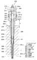
以下、本発明を図に示す実施形態について説明する。図1は、本発明の実施形態に係る燃焼圧センサ付きグロープラグ100の全体概略をディーゼルエンジン(内燃機関)のエンジンヘッド(被取付部)1へ取り付けた状態にて示す縦断面図である。
【0028】
グロープラグ100は、大きくは、発熱体を備えかつ燃焼圧伝達の媒体を果たすプラグ本体部200と、燃焼圧に伴いプラグ本体部200に作用する力を圧電素子の圧電特性に基づく電気信号に変換することによりエンジンの燃焼圧を検出する手段である圧力センサ(本発明でいう燃焼圧センサ)300と、を備えて構成されている。
【0029】
ここで、プラグ本体部200は、大きくは、一端側(図1中の下方側)が燃焼室1a側に位置し他端側(図1中の上方側)がエンジンヘッド1の外部に位置するようにエンジンヘッド1にネジ結合される金属製筒状のハウジング201と、一端側がハウジング201の一端から露出し他端側がハウジング201の内部に保持された筒状のシース管(本発明でいうパイプ部材)202と、シース管202の一端側に収納保持され通電により発熱する発熱コイル(本発明でいう発熱部材)203と、一端側がシース管202に挿入されて発熱コイル203に電気的に導通されるとともに他端側がハウジング201の他端から突出するようにハウジング201の内部に保持された金属製棒状の中軸(電極体、棒状電極)204とを備えている。
【0030】
エンジンヘッド1には、その外表面から内部の燃焼室1aまで貫通するネジ穴(グローホール)が形成されており、プラグ本体部200は、このネジ穴に対してプラグの軸方向(長手方向)に挿入されている。
【0031】
ハウジング201は、硫黄快削鋼または炭素鋼等からなり、その外形形状は一端側(燃焼室1a側)が小径で他端側が大径の段付形状になっている。そして、ハウジング201の小径部外周面におけるプラグ軸方向の中間部には取付ネジ部201bが形成されている。
【0032】
また、ハウジング201の大径部外周面にはグロープラグ100をエンジンヘッド1にネジ結合する際に利用される六角部201aが形成されている。そして、グロープラグ100のプラグ本体部200は、ハウジング201の取付ネジ部201bによって、エンジンヘッド1のネジ穴とネジ結合されている。
【0033】
また、ハウジング201の一端にはテーパ状のシート面201cが形成され、このシート面201cとこれに対向するエンジンヘッド1のネジ穴のシート面とが密着して、燃焼室1aからのガス漏れ防止がなされている。ここで、ハウジング201の六角部201aは、エンジン装着スペースに合わせて、六角部の頂角の一部を除去・円周面を形成して外形を細化しても良い(図示せず)。
【0034】
シース管202は、耐熱・耐食性合金(例えばステンレス材SUS310等)等よりなる。シース管202において、ハウジング201の一端から露出する一端側の先端部は閉塞し、ハウジング201内に位置する他端は開口している。また、発熱コイル203はNiCr及びCoFe等の抵抗線からなるもので、シース管202の先端側内部に配設されている。
【0035】
一方、シース管202の他端側内部には、中軸204の一端側が挿入配置されている。そして、発熱コイル203の他端はシース管202の一端に結合し、発熱コイル203の他端はシース管202に挿入された中軸204の一端に結合している。また、発熱コイル203及び中軸204とシース管202との問には、耐熱性を有する酸化マグネシウム等の絶縁粉末205が充填されている。
【0036】
シース管202にはスウェージングによる絞り加工が施されており、それによって、内部に充填された絶縁粉末205の緻密性を高めるている。つまり、絶縁粉末205の充填密度を高めることにより熱伝導効率を上げている。それとともに、上記絞り加工によって、該絶縁粉末205を介して中軸204及び発熱コイル203が、シース管202に強固に保持固定されている。
【0037】
ここで、シース管202のうち発熱コイル203を包含する部分において、これらシース管202、発熱コイル203及び絶縁粉末205により、発熱体206が構成されている。そして、発熱体206は、その先端部(シース管202の一端側)が露出するように、ハウジング201の一端側の内部に固定され保持されている。
【0038】
これら発熱体206の外周面すなわちシース管202の外周面とハウジング201の内周面とは、嵌合圧入による固着、または、銀ロウ等のロウ付けにより接合、固定されている。
【0039】
それによって、ハウジング201の一端側にてハウジング201の内面とシース管202の外面とが全周に渡って実質的に隙間無く固定された部分K1が固定部として形成される。そして、この固定部K1により、燃焼室1aからの燃焼ガスがハウジング201内部に侵入しないようになっている。
【0040】
なお、固定部K1は、図中の引き出し線にて指示されたハウジング201の内面とシース管202の外面とが接触している界面であり、プラグ径方向の全周に渡っていれば、当該界面の一部でも全部でも構わない。
【0041】
また、シース管202の他端(開口端)において、当該他端と中軸204との問には、絶縁粉末205がスウェージングの際に抜けないようにするためのシール部材(シーリング)205aが設けられている。
【0042】
また、ハウジング201の他端側の内部において、シリコンゴム、フッ素ゴム、EPDM、NBR、H−NBR等からなる円筒リング207が中軸204の他端側から挿入配置されている。
【0043】
ここで、円筒リング207は中軸204の芯出しと振動抑制及びハウジング201内の防水・気密性確保とを目的としたものである。そして、ハウジング201の他端側のうち円筒リング207と接触する部分をテーパ形状にすることによって、円筒リング207とハウジング201との密着性が良くなり、制振効果・防水・気密性はさらに向上する。
【0044】
また、中軸204の他端側には、樹脂系(例えばフェノール樹脂・PPS・積層マイカ)あるいはセラミック系(例えばアルミナ)の絶縁材料から成る絶縁ブッシュ210が嵌め込まれている。また、ハウジング201の六角部201aの内部には段付の大径穴部201dを設けることにより、その大径穴部201dと中軸204の外周面との問に収納部201eが形成されている。
【0045】
この収納部201eには略円環状の圧力センサ300(詳細後述)が収納されている。この圧力センサ300は、収納部201eに収納された後、絶縁ブッシュ210を中軸204に嵌め込み、中軸204の他端に設けられた端子ネジ204aに固定ナット211を締め付けることにより、絶縁ブッシュ210とハウジング201との間に固定保持されている。
【0046】
このように、ハウジング他端側の収納部201eに設けられた圧力センサ300は、固定ナット211の軸力によって、中軸204の一端側方向に向かってハウジング201へ押しつけるように固定されている。
【0047】
また、ハウジング201の大径穴部201dの内周面と圧力センサ300の外周面との問にはOリング208が配置され、圧力センサ300の内周面と中軸204の外周面との問には円筒リング209が挿入され配置されている。なお、このOリング208と円筒リング209は、シリコンゴム、フッ素ゴム、EPDM、NBR、H−NBR等からなる。
【0048】
ここで、Oリング208は、ハウジング201内の防水・気密性確保を目的としたものであり、円筒リング209は、中軸204の振動抑制とハウジング201内の防水・気密性確保とを目的としたものである。そして、センサ300の円筒リング209と接触する部分はテーパー形状にすると円筒リング209との密着性が良くなり、防水・気密性はさらに向上する。
【0049】
また、圧力センサ300と固定ナット211とは、絶縁ブッシュ210により電気的に絶縁されている。さらに、圧力センサ300と中軸204とは円筒リング209によって電気的に絶縁されている。
【0050】
また、中軸204の他端に設けられた端子ネジ204aには、各気筒問との結線用としてコネクティングバー2が端子ナット212によって固定され電気的に接続されている。このコネクティングバー2は図示しない電源に接続され、中軸204、発熱コイル203、シース管202、ハウジング201を介してエンジンヘッド1にアースされている。
【0051】
これにより、グロープラグ100において発熱体206は発熱し、ディーゼルエンジンの着火始動の補助を行うことが可能となっている。なお、各気筒間との結線にあたっては、シース管202(本発明でいうパイプ部材)の微小変位の妨げにならないよう、柔軟性に優れたリードワイヤ(自動車用電線)を用いても良い。
【0052】
[制振材について]
このような基本構成を有する本実施形態の燃焼圧センサ付きグロープラグ100においては、上述したように、中軸204のうちシース管202に挿入された一端側の部位は、シース管202の絞り加工によって絶縁粉末205を介してシース管202に固定されている。この中軸204におけるシース管202への固定部を第1の固定部204mとする。
【0053】
また、中軸204の他端側の部位は円筒リング207を介してハウジング201に固定されている。この中軸204におけるハウジング201への固定部を第2の固定部204nとする。直噴エンジンに用いる場合、この第1および第2の固定部204m、204n間の中軸204の長さは、例えば従来の2倍、約80mmである。
【0054】
そして、本実施形態では独自の構成として、中軸204のうちシース管202への固定部204mとハウジング201への固定部204nとの間の部位の周囲には、当該部位とハウジング201との間に、中軸204の振動を抑制するための制振材230が充填されている。
【0055】
この制振材230は、ゴムまたは樹脂等からなるものであり、その硬度は、デュロメータA10以上デュロメータD90以下であることが好ましい。なお、制振材230は成形品あるいは最終的に固形化(ゲル状を含む)するものであれば充填時は液状でも良い。
【0056】
より具体的に、制振材230としては、例えば、成形ゴム品では、フッ素ゴム、シリコンゴム、H−NBR等を採用でき、成形樹脂品では、エポキシ、フェノール、アクリル等を採用でき、液状ゴムでは、常温硬化型、加熱硬化型、硬化剤混合型のシリコンゴム等を採用でき、液状樹脂では、加熱硬化型、硬化剤混合型のエポキシ樹脂等を採用できる。
【0057】
[圧力センサの詳細構成]
次に、圧力センサ300の詳細構成を図2を参照して説明する。図2は、図1中の圧力センサ300の拡大断面図である。
【0058】
圧力センサ300においては、円環状の極性を有した圧電セラミックス302が、ともに略円環状をなすメタルケース303と電極301に挟持されるようにパッケージングされてなるものである。
【0059】
この圧電セラミックス302は例えば厚さ0.4mmのチタン酸鉛あるいはチタン酸ジルコン酸鉛からなるものである。また、圧力センサ300におけるメタルケース303および電極301とハウジング201の収納部201eとの間には、インシュレータ304が介在されている。
【0060】
このインシュレータ304は天然マイカ、積層マイカ及びアルミナ等のセラミックス材あるいは、ポリイミドフィルム、フェノール等の樹脂材からなるもので、例えば厚さ0.2mm程度のものである。インシュレータ304は、圧力センサ300で発生した出力信号がハウジング201ヘ短絡しない様、電極301を電気的に絶縁している。
【0061】
なお、メタルケース303および電極301における圧電セラミックス302との接触面は、表面粗さ6.3Z以下(例えば3.2Zや1.6Z)となるような研削または研磨加工を施すことにより平面度を向上させることが好ましい。
【0062】
それにより、メタルケース303および電極301が圧電セラミックス302と接触する面において面圧の均一化が図られ、密着性の向上と組み付け加圧時の素子割れを防止しやすくできる。ここで、メタルケース303と電極301の材質は、上記の研削又は研磨加工を容易にするため、磁性材である例えばSUS430を選定することができる。
【0063】
また、メタルケース303は大きくは略円環状のフランジ部303aと突出したパイプ状の小円形部303dで形成されているので、上記の研削又は研磨加工する上では、加工が容易ではない。そこで、メタルケース303をフランジ部と小円筒部に分離し、研削又は研磨力加工を必要とするフランジ部を単純な円盤状とし、加工後に双方をロウ付け等により一体化しても良い。
【0064】
また、メタルケース303の一端側のフランジ部303aには、プラグ軸方向に延びる貫通穴が形成されており、その貫通穴には筒状のプロテクションチューブ303bの一端が挿入され、溶接、ロウ付け等にて一体に形成されている。一方、絶縁ブッシュ210にもプラグ軸方向に延びる貫通穴210aが形成され、その貫通穴210aにプロテクションチューブ303bの他端が挿入されている。
【0065】
このプロテクションチューブ303bには、圧力センサ300の信号を取り出す出力線としてのシールド付き電線305が、挿入されて支持されるようになっている。メタルケース303内に挿入されたシールド付き電線305においては、その芯線305aが電極301に溶接されて結線されている。
【0066】
また、芯線305aとは絶縁されたシールド線305bは、プロテクションチューブ303bとかしめられることにより、ボディーアースでもあるメタルケース303に結線されている。
【0067】
なお、本例の圧力センサ300では、圧電セラミックス302を1枚としているが、その目的は、圧力センサ300の簡素化と低重心化を図り、圧力センサ300自体が発生する振動ノイズを低減し信号出力のS/N比を向上させることにある。
【0068】
しかし、上記した特許文献1の第2図に記載の圧力センサのように、圧電セラミックス302が2枚でも検出は可能である。なお、この場合、電極301の下側のインシュレータ304を排除し圧電セラミックス302を配置することとなる。このように、圧電セラミックス302を2枚並列結合させることにより、出力感度が2倍に高まり、出力信号の対ノイズ性が向上できる。
【0069】
[圧力センサの組付け方法]
この圧力センサ300の組付けは、次のようである。まず、メタルケース303の小径部303dの円周側面にシリコン製の熱収縮性の絶縁チューブ306を加熱して密着させる。
【0070】
次に、圧電セラミックス302、電極301の順に、これらをメタルケース303の小径部303dにはめ込む。ここで、絶縁チューブ306は、圧電セラミックス302および電極301とメタルケース303との電気的短絡を防止している。
【0071】
上記の組付け後、メタルケース303にはめ込まれた電極301に対して、シールド付き電線305の芯線305aを、抵抗溶接あるいはレーザ溶接等にて結線する。
【0072】
また、シールド付き電線305とプロテクションチューブ303bとをシールド線305bを含む部分でかしめる。それにより、シールド線305bとメタルケース303との電気的接続、シールド付き電線305の保持固定、及び、シールド付き電線305とプロテクションチューブ303bとの密着性を確保する。
【0073】
そして、このようにして、メタルケース303、圧電セラミックス302、電極301およびシールド付き電線305が一体化された圧力センサ300は、後述するように、ハウジング201の収納部201eへインシュレータ304を介して配設される。
【0074】
それにより、圧力センサ300は、金属性のメタルケース303と、金属性のプラグ本体部200により包含された形となる。その結果、完全密閉型かつ完全電気シールド型の圧力センサを提供することができる。
【0075】
[燃焼圧センサ付きグロープラグの組付方法]
次に、本実施形態の燃焼圧センサ付きグロープラグ100の組付方法について図1、図2を参照して説明する。まず、中軸204が組み付けられた発熱体206と、メッキを施したハウジング201とを用意する。用意される発熱体206におけるシース管202の外径は、ハウジング201の内径部に対してやや大きく、例えば+60〜+140μmの寸法差を有したものとする。
【0076】
そして、発熱体206のシース管202をハウジング201へ嵌合圧入し、ハウジング201とシース管202とを相互の弾性力で固着して密閉する。こうして、ハウジング201、中軸204及び発熱体206が一体化される。なお、ハウジング201と発熱体206との組付けは、上記以外に、双方を銀ロウ等のロウ付けにより完全接合しても良い。この結果、ハウジング201内部の高い気密性が確保出来る。
【0077】
このようにして、ハウジング201、中軸204及び発熱体206を一体化した後、ハウジング201と中軸204との隙間に制振材230を投入し充填する。制振材230の投入・充填のタイミングは、ハウジング201の内部において、円筒リング207が中軸204の他端側から挿入配置される前に実施する。
【0078】
制振材230が成形ゴム品や成形樹脂品の場合、例えば、外観上は厚さ5mmの円筒状としたものを、中軸204の他端側から中軸204に挿入するとともにハウジング201の他端側開口部から投入し、中軸204とハウジング201との間に配置する。
【0079】
このとき、確実に制振材230自身も保持されるように、制振材230の径方向の圧縮率を10〜30%以内として内外径のつぶし代を設定する。そして、投入の際は、予め制振材230の内外周に潤滑材を塗布し、中軸204他端の端子ネジ204a側より所定位置に達するまで圧入する。このとき、制振材230の数は必要に応じて増やしても良い。なお、制振材230が成形品であると、組付け作業は非常に効率的となる。
【0080】
また、制振材230が液状ゴムや液状樹脂を素材とする場合、例えば定量化可能なディスペンサを用いて、ハウジング201他端の開口部ヘノズルを挿入して注入する。このとき、粘度に応じては真空脱泡することにより、より気泡が無く密度の高い充填が可能となる。その後、制振材230の硬化条件に沿って硬化させる。
【0081】
なお、制振材230の素材が液状品であると、容易にハウジング201空間内に充填させることができ、エンジン振動が大きくなる大排気量向けエンジン用の燃焼圧センサ付きグロープラグには有効である。
【0082】
こうして、制振材230を配置した後、中軸204の他端側(つまり、端子ネジ204a側)からハウジング201内に、円筒リング207、インシュレータ304を順に投入して配置する。そして、フランジ部303aの外周にOリング208を挿入した状態で、圧力センサ300を収納部201e内に配置する。
【0083】
続いて、中軸204の他端側より円筒リング209を投入し、さらには、圧力センサ300に結線されたシールド付き電線305の他端側よりOリング309を投入し、所定場所に配置する。この状態にて絶縁ブッシュ210を中軸204の他端側より投入するとともに、シールド付き電線305は、絶縁ブッシュ210の貫通穴210aを通して外部へ導出する。
【0084】
なお、図2に示すように、Oリング309は、シールド付き電線305の外周面とプロテクションチューブ303bの端面と絶縁ブッシュ210に設けた貫通穴210aの底部端面に接触するように押圧され挿入されている。このOリング309は、シリコンゴム、フッ素ゴム、EPDM、NBR、H−NBR等からなるもので、防水、防振を目的としたものである。
【0085】
また、絶縁ブッシュ210は、樹脂系(例えばフェノール樹脂、PPS、積層マイカ)あるいはセラミック系(例えばアルミナ)の絶縁材料であれば問題はないが、好ましくは、比重が小さく、ヤング率が大きく、クリープ特性に優れた素材が有効である。
【0086】
これにより、絶縁ブッシュ210を軽くして圧力センサ300の低重心化が図られ、振動ノイズレベルを低減できる。また、絶縁ブッシュ210の経時変化すなわちクリープを抑制できるため、このクリープに伴う圧力センサ300に印加される予荷重(つまり固定ナット211による圧力センサ300の加圧力)の変化で生じる出力変動を、低減できる。
【0087】
そこで、絶縁ブッシュ210としては、例えばガラス繊維を配合した熱硬化性のフェノール樹脂を選定し、さらに熱処理として例えば175℃〜205℃、3〜20時間加熱を加えることによりクリープ特性を改善したものを採用できる。
【0088】
こうして、絶縁ブッシュ210まで組み付けた後、中軸204の端子ネジ204aに沿って固定ナット211を締め付けることにより、圧力センサ300を収納部201e内に固定して保持する。
【0089】
なお、固定ナット211を締め付けた後、固定ナット211の六角面の1箇所をかしめて変形させるか、あるいは予め螺着面(ネジの部分)にネジロック剤を塗布して固定ナット211を締め付けることで、振動に対する固定ナット211の緩み防止策を講じても良い。
【0090】
また、絶縁ブッシュ210は、略円環状のものであるが、その円周面の一部に対向し合うフラットな2面を有するものとして良い。このような絶縁ブッシュ210を用いれば、完全に円環状のものに比べて、固定ナット211を締め付ける際に、絶縁ブッシュ210の対向し合うフラットな2面をスパナ等で拘束することで、絶縁ブッシュ210が回転しないように固定ナット211を回転させることができる。
【0091】
それにより、圧力センサ300を構成する圧電セラミック302や電極301と芯線305aとの溶接部へのねじり力を回避しつつ、圧力センサ300へ予荷重を加えることが可能となる。これにより、圧電セラミック302や芯線305へのねじりによる破壊や破断を防止することができる。
【0092】
このようにして、固定ナット211を締め付けて圧力センサ300を固定した後、ハウジング201をエンジンヘッド1にネジ結合して取り付け、次に、固定ナット211の上面にて、コネクティングバー2を端子ネジ204aに取り付け、端子ナット212で固定する。こうして、上記図1に示す状態になる。
【0093】
[燃焼圧センサ付きグロープラグにおける燃焼圧の検出メカニズム]
次に、本実施形態のグロープラグ100における基本的な燃焼圧の検出メカニズムについて、上記図1、図2に加えて、図3も参照して説明する。図3は、燃焼圧の伝達経路を説明するための簡略モデルを示す説明図(半断面図)である。
【0094】
上記図1において、圧力センサ300は予め固定ナット211により、プラグ本体部200に固定保持され一体化が図られている。この時、圧力センサ300に内蔵されている圧電セラミックス302には、エンジン装着後に所定の予荷重が負荷されるように、グロープラグ100がエンジンヘッド1に装着されている。
【0095】
エンジン始動時、コネクテイングバー2を介して電圧が印加され、中軸204、発熱コイル203、シース管202、ハウジング201、取付けネジ部201bを介してエンジンヘッド1にアースされる。
【0096】
これにより、グロープラグ100における発熱体206が発熱し、ディーゼルエンジンの着火始動の補助を行うことができる。そして、エンジン始動後、エンジン内で発生した燃焼圧は、図3の太線矢印に示す如く2つの経路R1及びR2に分散され、圧力センサ300に作用する。
【0097】
第1の経路R1は、発熱体206に印加された燃焼圧が、発熱体206と接合されたハウジング201に伝達され、圧力センサ300に作用するものである。この経路R1においては、ハウジング201自体は取付けネジ部201bによりエンジンヘッド1へ強固に拘束されている。
【0098】
そのため、それより上部では力の伝達は著しく減衰され、圧力センサ300が配置されているハウジング201の収納部201e近傍の位置変動は極めて小さい。
【0099】
一方、第2の経路R2は、発熱体206に印加された燃焼圧が、発熱体206自身に充填された絶縁粉末205、中軸204、固定ナット211、絶縁ブッシュ210の4つの部材を介して圧力センサ300に作用するものである。この経路R2においては、これら4つの部材には位置変動を阻害する部材等の要因は無く、全く開放されている。
【0100】
また、ハウジング201とシース管202とが固定部K1にて固定されていても、シース管202は、ハウジング201の弾性力を利用してプラグの軸方向(図3中の上下方向)へ変位できる。そのため、第2の経路R2に沿って発熱体206に燃焼圧が印加されたとき、シース管202及び中軸204は一体に、プラグの軸方向へ変位する。
【0101】
この結果、第1の経路R1で発生するハウジング201の収納部201e近傍の変位量と、第2の経路R2で発生する主たる中軸204の変位量とでは差が生じる。つまり、第2の経路R2の変位量の方が第1の経路R1の変位量よりも大きくなる。この変動に伴い、圧力センサ300には、固定ナット211にて予め負荷されている予荷重が緩和される。
【0102】
こうして、圧力センサ300に内蔵された圧電セラミックス302に負荷される荷重状態が変化するために、圧電セラミックス302の有する圧電特性に伴って出力される電気信号としての発生電荷が変化する。
【0103】
そして、この電気信号は、図2に示す電極301を介してシールド付き電線305の芯線305aと、アースであるメタルケース303、プロテクションチューブ303bを介してアース線を兼用したシールド線305bとの問に出力される。
【0104】
この出力信号を、シールド付き電線305を介して、出力である発生電荷を電圧に変換して増幅させるチャージアンプ(図示せず)及び車載ECU(エンジン制御回路/図示せず)へ入力することによって、燃焼圧を電気信号として、燃焼制御に応用することができる。本実施形態の燃焼圧の検出メカニズムは、以上であるが、図4に本実施形態による検出波形の一例を示す。
【0105】
[検出波形の一例]
図4(a)及び(b)は、図1に示したグロープラグ100において、エンジン条件を1200rpmで40N負荷時とした場合の検出結果を示している、図4において、(a)は、指圧計のエンジン出力波形(つまり基準筒内圧)とグロープラグ100における圧力センサ300の出力波形(実施形態)との比較図、(b)は、グロープラグ100における圧力センサ300からの出力を縦軸に、指圧計からの出力を横軸にとった相関出力波形を示す。
【0106】
図4からわかる様に、本グロープラグ100における圧力センサ300からの出力と指圧計からの出力とはほぼ同一形状波形を示し、また、相関出力波形も圧力上昇時、減少時を含めほぼ直線的な値を示し応答性に優れていることがわかる。
【0107】
このことから、本グローブラグ100による燃焼圧の検出において、エンジン内の圧力変動に対応して圧力センサ300に作用する荷重の変動が正確に測定できていることがわかる。つまり、SN比が小さく、ヒステリシスがほとんどなく応答性に優れた出力特性を実現できている。
【0108】
[本実施形態の効果等について]
このように、本実施形態において、中軸204を長くしても中軸204の振動により発生する出力ノイズが抑制され、安定した出力特性が得られるのは、中軸204のうち第1の固定部204mと第2の固定部204nとの間の部位の周囲に、本実施形態独自の構成として制振材230を新たに設けたことによる。
【0109】
従来の構成(図7参照)では、第1および第2の固定部204m、204nの2点で中軸の固定保持がなされており、中軸204の長尺化に伴って発生する振動を抑制できなかった。
【0110】
しかし、本実施形態では、両固定部204m、204nの間に制振材230を新たに設けることで、中軸204が長くなっても中軸204の支点間距離tを短くできる。図1の例では、支点間距離tは、制振材230と第2の固定部204nとの間の距離である。
【0111】
そのため、本実施形態では、中軸204が長くなっても、エンジン振動に起因する中軸204の共振周波数の低周波数帯への移行を防止し、且つ振動レベル自体の増大も抑制できる。
【0112】
そのため、圧力センサ300に伝達される中軸204の機械振動が、機械振動ノイズとして燃焼圧信号に重畳して出力されても、SN比を従来レベルに維持することができる。その結果、本実施形態では、中軸204を長くしても中軸204の振動により発生する出力ノイズを抑制できるという効果が発揮されるのである。
【0113】
なお、中軸204の長尺化による中軸204の共振周波数の低周波数帯への移行の防止については、実用的には、5kHz以下の低周波数帯に移行しなければよい。これは、燃焼圧の周波数帯域が約5kHz以下であることから、それ以上の周波数の振動は、電気的にローパスフィルタ等を用いて、出力信号から排除しているためである。
【0114】
また、上述したように、制振材230の硬度は、デュロメータA10以上デュロメータD90以下であることが好ましい。これは、本発明者らの検討結果によるものである。制振材230の硬度がデュロメータA10未満と軟らかすぎると、制振材230による中軸204の保持強度が低いため、制振材230自体も中軸204とともに振動する結果、中軸204の振動を抑制しにくくなる。
【0115】
一方、制振材230の硬度がデュロメータD90より大きく硬すぎても振動抑制に対しては効果を発揮する。しかし、中軸204とハウジング201が制振材230により強固に固着した場合、燃焼圧に応じた軸方向の荷重がシース管202に印加されても、中軸204は制振材230によってハウジング201に拘束されているため、圧力センサ300ヘの微小変位の伝達が阻害される。そのため、出力感度が激減し、結果的にはSN比が悪化することとなる。
【0116】
ちなみに、制振材230の硬度が高くても強固に固着しなければ、すなわち中軸204と制振材230との間あるいはハウジング201と制振材230との間に微小な隙間をもたせれば、中軸204の微小変位の圧力センサ300への伝達が阻害されないと考えられる。
【0117】
例えば、制振材230が保持された状態で、中軸204と制振材230との隙間を50μ以下とすれば、中軸204の振動の抑制効果が得られると考えられるが、そのような微小な隙間を制御することは事実上困難と考えられる。
【0118】
実際に、制振材230の硬度を検討した例を図5に示す。図5は、制振材230の硬度とセンサ出力のノイズ比率との関係を調べた結果を示す図である。なお、ノイズ比率(%)は、上記図4(a)中の圧力センサ300の出力波形におけるピーク高さ(センサ出力の波高値)hに対するノイズの振幅(センサ出力のノイズ幅)の比率であり、小さいほど良い。
【0119】
従来品すなわち中軸204の両固定部204m、204n間の距離が40mm程度のグロープラグにおいては、図5中に示すように、ノイズ比率は4%程度であった。
【0120】
本検討例では、中軸204の両固定部204m、204n間の距離が80mm程度のグロープラグについて、制振材230無しの場合、制振材230としてデュロメータA10のシリコンゴム、デュロメータA50のシリコンゴム、デュロメータA90のシリコンゴム、デュロメータD90のエポキシ樹脂をそれぞれ用いた場合について調べた。
【0121】
その結果、長尺化した中軸204に対して、制振材230の硬度がデュロメータA10以上であれば、従来レベルのノイズ比率を維持できることが確認できた。なお、デュロメータD90より硬度が大きい場合は、上記した理由から好ましくない。
【0122】
また、制振材230の配置位置は、中軸204における第1の固定部204mと第2の固定部204nとの間であれば、任意の位置に配置できる。ただし、第1の固定部(中軸におけるシース管への固定部)204m、第2の固定部(中軸におけるハウジングへの固定部)204n、制振材230の間の距離が、40mm以下であることが好ましい。
【0123】
図1の例では、この距離は、制振材230と第2の固定部204nとの間の支点間距離tであり、この支点間距離tが40mm以下となるように、制振材230を配置することが好ましい。これは、従来のグロープラグにおける支点間距離が40mm程度であり、この従来品の場合、上記図5に示したように、実用レベルのノイズ比率となっていることによる。
【0124】
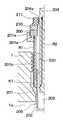
また、制振材230は複数個配置されていても良い。そのような変形例を図6に示す。図6は、本実施形態の変形例としての燃焼圧センサ付きグロープラグ100の全体概略縦断面図である。
【0125】
中軸204における第1の固定部204mと第2の固定部204nとの間に複数個(図6では2個)の制振材230が配置されている。この場合も、上記した本実施形態の効果を発揮できることはもちろんである。
【0126】
また、この図6の例では、第1の固定部204mと下側の制振材230との距離t1、下側の制振材230と上側の制振材230との距離t2、上側の制振材230と第2の固定部204nとの距離t3の各距離t1〜t3が支点間距離であり、これら支点間距離t1〜t3が40mm以下であることが好ましい。この理由は、上記と同様である。
【0127】
なお、本発明は、長尺な直噴エンジン用グロープラグに限定されるものでは無く、効果としては小さいが従来品に適用させても良い。
【図面の簡単な説明】
【図1】本発明の実施形態に係る燃焼圧センサ付きグロープラグの全体概略断面図である。
【図2】図1中の圧力センサの拡大断面図である。
【図3】燃焼圧の伝達経路を説明するための簡略モデルを示す図である。
【図4】上記実施形態による燃焼圧の検出波形の一例を示す図である。
【図5】制振材の硬度とセンサ出力のノイズ比率との関係を示す図である。
【図6】上記実施形態の変形例としての燃焼圧センサ付きグロープラグ全体概略断面図である。
【図7】一般的な燃焼圧センサ付きグロープラグの概略断面構成を示す図である。
【符号の説明】
1a…燃焼室、201…ハウジング、202…シース管、
203…発熱コイル、204…中軸、
204m…中軸におけるシース管への固定部としての第1の固定部、
204n…中軸におけるハウジングへの固定部としての第2の固定部、
230…制振材、300…圧力センサ、t、t1、t2、t3…支点間距離。[0001]
TECHNICAL FIELD OF THE INVENTION
The present invention relates to a glow plug with a combustion pressure sensor having a combustion pressure sensor for detecting a combustion pressure in a combustion chamber of an engine.
[0002]
[Prior art]
FIG. 7 shows a schematic sectional configuration of a general glow plug with a combustion pressure sensor of this type (see, for example, Patent Document 1).
[0003]
The glow plug J100 has a
[0004]
The
[0005]
Inside the
[0006]
Further, inside the
[0007]
In the
[0008]
A
[0009]
The
[0010]
When such a glow plug J100 is mounted on the engine, when a pressure in the
[0011]
The displacement of the
[0012]
[Patent Document 1]
JP 2001-124336 A (Pages 3-5, FIG. 1)
[0013]
[Problems to be solved by the invention]
By the way, in recent years, direct injection of a diesel engine is becoming mainstream in view of improvement of fuel efficiency and regulation of exhaust gas. As a result, glow plugs have had to adapt to engine trends.
[0014]
The fact is that the glow plug has a longer overall length than the conventional engine due to the limited space for glove lugs on the engine due to the thickening of the engine head and the use of four valves. Is being scaled. For example, it is about twice as long as the conventional one.
[0015]
Therefore, when the glow plug with a combustion pressure sensor for the conventional engine shown in FIG. 7 is applied to a direct injection engine, the
[0016]
However, in a glow plug with a combustion pressure sensor for a direct injection engine, if the
[0017]
As a result, the resonance frequency of the
[0018]
In view of the above problems, it is an object of the present invention to provide a glow plug with a combustion pressure sensor that suppresses output noise generated by vibration of a center shaft even when the center shaft is lengthened.
[0019]
[Means for Solving the Problems]
In order to achieve the above object, according to the first aspect of the present invention, a cylindrical housing (201) attached to an engine such that one end is positioned on a side of a combustion chamber (1a) of the engine, and one end is formed from one end of the housing. A pipe member (202) held inside the housing so as to be exposed, a heating member (203) provided in the pipe member and generating heat by energization, and one end side inserted into the pipe member while being housed in the housing. A metal middle shaft (204) electrically connected to the heat generating member, and a combustion pressure sensor for detecting a combustion pressure by transmitting a force acting on a pipe member as the combustion pressure of the engine is generated through the middle shaft ( 300), a portion of the center shaft at one end inserted into the pipe member is fixed to the pipe member, and a portion at the other end of the center shaft is fixed to the housing. In combustion pressure glow plug with sensor being,
Around the portion of the center shaft between the portion for fixing to the pipe member (204m) and the portion for fixing to the housing (204n) is filled with a space between the portion and the housing to suppress vibration of the center shaft. A vibration material (230) is provided.
[0020]
According to this, the vibration of the center shaft can be suppressed even if the center shaft becomes longer by newly providing a vibration damping material between the two fixed portions (204m, 204n). Therefore, in the glow plug with a combustion pressure sensor, even if the central shaft is lengthened, output noise generated by vibration of the central shaft can be suppressed.
[0021]
According to the second aspect of the present invention, the fixed portion (204m) of the center shaft (204) to the pipe member (202), the fixed portion (204n) of the center shaft to the housing (201), and the vibration damping material (230) Is characterized in that the damping material is arranged so that the distance (t, t1 to t3) between them is 40 mm or less.
[0022]
According to the study results of the present inventors, the magnitude of the output noise can be suppressed to a practical level if the length of the center axis of the non-fixed portion is 40 mm or less. Is preferable.
[0023]
Here, if the vibration damping material is too soft, the holding strength of the central shaft is low, so that vibration of the central shaft cannot be suppressed. On the other hand, if the damping material is too hard, when the center shaft and the housing are firmly fixed by the damping material, the restraint of the center shaft by the housing is strong, and the transmission of minute displacement of the center shaft to the combustion pressure sensor is hindered, and the sensor output Sensitivity decreases.
[0024]
According to the result of examining the hardness of the damping material in consideration of such points, the hardness of the damping material (230) is in the range of durometer A10 or more and durometer D90 or less as in the invention of claim 3. Preferably, there is.
[0025]
Further, as in the invention described in claim 4, the damping material (230) can be made of rubber or resin.
[0026]
It should be noted that reference numerals in parentheses of the above-described units are examples showing the correspondence with specific units described in the embodiments described later.
[0027]
BEST MODE FOR CARRYING OUT THE INVENTION
Hereinafter, embodiments of the present invention shown in the drawings will be described. FIG. 1 is a longitudinal sectional view showing a general outline of a
[0028]
The
[0029]
Here, the plug
[0030]
The
[0031]
The
[0032]
A
[0033]
Further, a
[0034]
The
[0035]
On the other hand, inside the other end side of the
[0036]
The
[0037]
Here, in a portion of the
[0038]
The outer peripheral surface of the
[0039]
Thereby, a portion K1 in which the inner surface of the
[0040]
The fixing portion K1 is an interface where the inner surface of the
[0041]
At the other end (open end) of the
[0042]
A
[0043]
Here, the
[0044]
An insulating
[0045]
The
[0046]
As described above, the
[0047]
Further, an O-
[0048]
Here, the O-
[0049]
The
[0050]
A connecting
[0051]
As a result, the
[0052]
[About damping materials]
In the
[0053]
The other end of the
[0054]
In the present embodiment, as a unique configuration, a portion around the portion between the fixing
[0055]
The damping
[0056]
More specifically, as the
[0057]
[Detailed configuration of pressure sensor]
Next, a detailed configuration of the
[0058]
In the
[0059]
The piezoelectric ceramic 302 is made of, for example, lead titanate or lead zirconate titanate having a thickness of 0.4 mm. Further, an
[0060]
The
[0061]
The contact surfaces of the
[0062]
As a result, the surface pressure of the surface where the
[0063]
Further, since the
[0064]
A through hole extending in the axial direction of the plug is formed in the
[0065]
A shielded
[0066]
In addition, the
[0067]
In the
[0068]
However, like the pressure sensor described in FIG. 2 of
[0069]
[Assembly method of pressure sensor]
The assembly of the
[0070]
Next, these are fitted into the
[0071]
After the assembly, the
[0072]
Also, the shielded
[0073]
Then, the
[0074]
As a result, the
[0075]
[Assembly method of glow plug with combustion pressure sensor]
Next, a method of assembling the
[0076]
Then, the
[0077]
After the
[0078]
When the
[0079]
At this time, the compression allowance of the inner and outer diameters is set with the radial compression ratio of the damping
[0080]
When the damping
[0081]
If the material of the damping
[0082]
After the damping
[0083]
Subsequently, the
[0084]
As shown in FIG. 2, the O-
[0085]
The insulating
[0086]
Thus, the weight of the insulating
[0087]
Therefore, as the insulating
[0088]
After assembling up to the insulating
[0089]
After tightening the fixing
[0090]
Further, the insulating
[0091]
This makes it possible to apply a preload to the
[0092]
After fixing the
[0093]
[Detection mechanism of combustion pressure in glow plug with combustion pressure sensor]
Next, a basic combustion pressure detection mechanism in the
[0094]
In FIG. 1 described above, the
[0095]
When the engine is started, a voltage is applied via the connecting
[0096]
As a result, the
[0097]
In the first path R1, the combustion pressure applied to the
[0098]
For this reason, the transmission of the force is significantly attenuated above, and the positional fluctuation in the vicinity of the
[0099]
On the other hand, the second path R2 is a state in which the combustion pressure applied to the
[0100]
Even if the
[0101]
As a result, there is a difference between the amount of displacement of the
[0102]
Thus, since the load state applied to the
[0103]
Then, this electric signal is interrogated by the
[0104]
By inputting this output signal via a shielded
[0105]
[Example of detected waveform]
FIGS. 4A and 4B show detection results when the engine conditions are set to 1200 rpm and a 40 N load is applied to the
[0106]
As can be seen from FIG. 4, the output from the
[0107]
From this, it can be seen that in the detection of the combustion pressure by the
[0108]
[Effects of the Embodiment]
As described above, in the present embodiment, even if the
[0109]
In the conventional configuration (see FIG. 7), the center shaft is fixedly held at the first and second fixing
[0110]
However, in the present embodiment, by newly providing the
[0111]
Therefore, in the present embodiment, even if the
[0112]
Therefore, even if the mechanical vibration of the
[0113]
In order to prevent the shift of the resonance frequency of the
[0114]
Further, as described above, the hardness of the damping
[0115]
On the other hand, even if the hardness of the damping
[0116]
Incidentally, even if the hardness of the damping
[0117]
For example, if the gap between the
[0118]
FIG. 5 shows an example in which the hardness of the damping
[0119]
In a conventional product, that is, a glow plug in which the distance between the fixing
[0120]
In the present study example, for a glow plug in which the distance between the two fixing
[0121]
As a result, it was confirmed that the noise ratio of the conventional level can be maintained when the hardness of the
[0122]
Further, the damping
[0123]
In the example of FIG. 1, this distance is the distance t between fulcrums between the damping
[0124]
Further, a plurality of
[0125]
A plurality (two in FIG. 6) of
[0126]
In the example of FIG. 6, the distance t1 between the first fixed
[0127]
Note that the present invention is not limited to a long glow plug for a direct injection engine, and may be applied to a conventional product although the effect is small.
[Brief description of the drawings]
FIG. 1 is an overall schematic sectional view of a glow plug with a combustion pressure sensor according to an embodiment of the present invention.
FIG. 2 is an enlarged sectional view of the pressure sensor in FIG.
FIG. 3 is a diagram showing a simplified model for explaining a transmission path of a combustion pressure.
FIG. 4 is a diagram showing an example of a combustion pressure detection waveform according to the embodiment.
FIG. 5 is a diagram showing the relationship between the hardness of the damping material and the noise ratio of the sensor output.
FIG. 6 is an overall schematic cross-sectional view of a glow plug with a combustion pressure sensor as a modification of the embodiment.
FIG. 7 is a diagram showing a schematic cross-sectional configuration of a general glow plug with a combustion pressure sensor.
[Explanation of symbols]
1a: combustion chamber, 201: housing, 202: sheath tube,
203: heating coil, 204: center shaft,
204m: a first fixing portion as a fixing portion to the sheath tube in the center shaft,
204n: a second fixing portion as a fixing portion to the housing of the center shaft,
230: damping material, 300: pressure sensor, t, t1, t2, t3: distance between fulcrums.
Claims (4)
Translated fromJapanese一端側が前記ハウジングの前記一端から露出するように前記ハウジングの内部に保持されたパイプ部材(202)と、
前記パイプ部材内に設けられ、通電により発熱する発熱部材(203)と、
前記ハウジング内に収納されるとともに、一端側が前記パイプ部材に挿入されて前記発熱部材と電気的に導通されている金属製の中軸(204)と、
前記エンジンの燃焼圧の発生に伴い前記パイプ部材に作用する力が前記中軸を介して伝達されて前記燃焼圧を検出する燃焼圧センサ(300)とを備え、
前記中軸のうち前記パイプ部材に挿入された前記一端側の部位が前記パイプ部材に固定されるとともに、前記中軸の他端側の部位が前記ハウジングに固定されている燃焼圧センサ付きグロープラグにおいて、
前記中軸のうち前記パイプ部材への固定部(204m)と前記ハウジングへの固定部(204n)との間の部位の周囲には、当該部位と前記ハウジングとの間に充填され前記中軸の振動を抑制するための制振材(230)が設けられていることを特徴とする燃焼圧センサ付きグロープラグ。A cylindrical housing (201) attached to the engine such that one end is located on the combustion chamber (1a) side of the engine;
A pipe member (202) held inside the housing so that one end side is exposed from the one end of the housing;
A heat generating member (203) provided in the pipe member and generating heat by energization;
A metal center shaft (204) housed in the housing and having one end inserted into the pipe member and electrically connected to the heating member;
A combustion pressure sensor (300) for transmitting a force acting on the pipe member with the generation of the combustion pressure of the engine through the center shaft and detecting the combustion pressure;
A glow plug with a combustion pressure sensor, wherein the one end portion of the middle shaft inserted into the pipe member is fixed to the pipe member, and the other end portion of the middle shaft is fixed to the housing.
Around the portion of the center shaft between the fixing portion (204m) to the pipe member and the fixing portion (204n) to the housing, the vibration of the center shaft is filled between the portion and the housing. A glow plug with a combustion pressure sensor, comprising a damping material (230) for suppressing the vibration.
Priority Applications (3)
| Application Number | Priority Date | Filing Date | Title |
|---|---|---|---|
| JP2002293747AJP3900060B2 (en) | 2002-10-07 | 2002-10-07 | Glow plug with combustion pressure sensor |
| FR0311497AFR2845462B1 (en) | 2002-10-07 | 2003-10-01 | PREHEATING PLUG WITH COMBUSTION PRESSURE SENSOR |
| DE10346296.1ADE10346296B4 (en) | 2002-10-07 | 2003-10-06 | Glow plug with combustion pressure sensor |
Applications Claiming Priority (1)
| Application Number | Priority Date | Filing Date | Title |
|---|---|---|---|
| JP2002293747AJP3900060B2 (en) | 2002-10-07 | 2002-10-07 | Glow plug with combustion pressure sensor |
Publications (2)
| Publication Number | Publication Date |
|---|---|
| JP2004124911Atrue JP2004124911A (en) | 2004-04-22 |
| JP3900060B2 JP3900060B2 (en) | 2007-04-04 |
Family
ID=32025485
Family Applications (1)
| Application Number | Title | Priority Date | Filing Date |
|---|---|---|---|
| JP2002293747AExpired - Fee RelatedJP3900060B2 (en) | 2002-10-07 | 2002-10-07 | Glow plug with combustion pressure sensor |
Country Status (3)
| Country | Link |
|---|---|
| JP (1) | JP3900060B2 (en) |
| DE (1) | DE10346296B4 (en) |
| FR (1) | FR2845462B1 (en) |
Cited By (15)
| Publication number | Priority date | Publication date | Assignee | Title |
|---|---|---|---|---|
| JP2006336918A (en)* | 2005-06-01 | 2006-12-14 | Denso Corp | Glow plug with combustion pressure sensor |
| JP2008076155A (en)* | 2006-09-20 | 2008-04-03 | Denso Corp | Pressure sensor |
| JP2008151455A (en)* | 2006-12-19 | 2008-07-03 | Ngk Spark Plug Co Ltd | Glow plug and manufacturing method thereof |
| JP2008537046A (en)* | 2005-04-11 | 2008-09-11 | ローベルト ボツシユ ゲゼルシヤフト ミツト ベシユレンクテル ハフツング | Sheath type glow plug with built-in pressure measuring element |
| JP2008298530A (en)* | 2007-05-30 | 2008-12-11 | Ngk Spark Plug Co Ltd | Pressure detector |
| US7905209B2 (en) | 2007-08-30 | 2011-03-15 | Denso Corporation | Glow plug with combustion pressure sensor |
| JP2012021769A (en)* | 2011-11-02 | 2012-02-02 | Ngk Spark Plug Co Ltd | Glow plug |
| JP2012215524A (en)* | 2011-04-01 | 2012-11-08 | Denso Corp | Combustion pressure sensor |
| JP2013170774A (en)* | 2012-02-22 | 2013-09-02 | Ngk Spark Plug Co Ltd | Glow plug |
| JP2013174439A (en)* | 2013-06-13 | 2013-09-05 | Ngk Spark Plug Co Ltd | Glow plug |
| JP2013234780A (en)* | 2012-05-07 | 2013-11-21 | Ngk Spark Plug Co Ltd | Glow plug |
| JP2015064196A (en)* | 2013-09-25 | 2015-04-09 | ローベルト ボッシュ ゲゼルシャフト ミット ベシュレンクテル ハフツング | Sheath type glow plug for internal combustion engine |
| JP5740002B2 (en)* | 2012-03-28 | 2015-06-24 | 日本特殊陶業株式会社 | Glow plug |
| JP2016075454A (en)* | 2014-10-09 | 2016-05-12 | 日本特殊陶業株式会社 | Glow plug |
| JP2023049395A (en)* | 2021-09-29 | 2023-04-10 | シチズンファインデバイス株式会社 | Pressure sensing device |
Families Citing this family (5)
| Publication number | Priority date | Publication date | Assignee | Title |
|---|---|---|---|---|
| DE102004011098A1 (en)* | 2004-03-06 | 2005-09-22 | Robert Bosch Gmbh | Device for detecting the combustion chamber pressure in an internal combustion engine |
| DE102004047143A1 (en)* | 2004-09-29 | 2006-04-06 | Robert Bosch Gmbh | Piezoelectric combustion chamber pressure sensor with a pressure transfer pin |
| JP4316474B2 (en) | 2004-11-02 | 2009-08-19 | 株式会社デンソー | Combustion chamber pressure detector |
| DE102008009441B4 (en)* | 2008-02-13 | 2011-08-25 | Beru AG, 71636 | pressure measuring glow |
| FR2949537B1 (en)* | 2009-09-01 | 2012-11-16 | Continental Automotive France | PREHEATING PLUG INCORPORATING A FORCE SENSOR AND TWO MEMBRANES |
Family Cites Families (10)
| Publication number | Priority date | Publication date | Assignee | Title |
|---|---|---|---|---|
| US3319130A (en)* | 1964-07-22 | 1967-05-09 | Fuel Ignition Ltd | Electrical ignitors |
| DE2609294A1 (en)* | 1976-03-06 | 1977-09-15 | Bosch Gmbh Robert | PROCEDURE FOR FASTENING A GLOW PLUG IN THE HOUSING OF A GLOW PLUG FOR COMBUSTION MACHINERY |
| DE2835236C2 (en)* | 1978-08-11 | 1986-05-28 | Robert Bosch Gmbh, 7000 Stuttgart | Sheathed-element glow plugs for internal combustion engines |
| US4475030A (en)* | 1981-09-25 | 1984-10-02 | Caterpillar Tractor Co. | Glow plug having resiliently mounted ceramic surface-ignition element |
| JPS5960237A (en)* | 1982-09-30 | 1984-04-06 | Nippon Soken Inc | Glow plug with built-in internal pressure detector |
| JPS5985932A (en)* | 1982-11-09 | 1984-05-18 | Nippon Soken Inc | Glow plug |
| SE506535C2 (en)* | 1995-06-16 | 1998-01-12 | Ericsson Telefon Ab L M | Method and apparatus for deriving instance information in an information management system |
| JP3911930B2 (en) | 1999-10-28 | 2007-05-09 | 株式会社デンソー | Glow plug with combustion pressure sensor |
| JP4300663B2 (en)* | 1999-12-24 | 2009-07-22 | 株式会社デンソー | Combustion pressure sensor structure |
| JP3885515B2 (en)* | 2001-04-26 | 2007-02-21 | 株式会社デンソー | Glow plug with combustion pressure sensor |
- 2002
- 2002-10-07JPJP2002293747Apatent/JP3900060B2/ennot_activeExpired - Fee Related
- 2003
- 2003-10-01FRFR0311497Apatent/FR2845462B1/ennot_activeExpired - Fee Related
- 2003-10-06DEDE10346296.1Apatent/DE10346296B4/ennot_activeExpired - Fee Related
Cited By (17)
| Publication number | Priority date | Publication date | Assignee | Title |
|---|---|---|---|---|
| JP2008537046A (en)* | 2005-04-11 | 2008-09-11 | ローベルト ボツシユ ゲゼルシヤフト ミツト ベシユレンクテル ハフツング | Sheath type glow plug with built-in pressure measuring element |
| JP2006336918A (en)* | 2005-06-01 | 2006-12-14 | Denso Corp | Glow plug with combustion pressure sensor |
| JP2008076155A (en)* | 2006-09-20 | 2008-04-03 | Denso Corp | Pressure sensor |
| JP2008151455A (en)* | 2006-12-19 | 2008-07-03 | Ngk Spark Plug Co Ltd | Glow plug and manufacturing method thereof |
| JP2008298530A (en)* | 2007-05-30 | 2008-12-11 | Ngk Spark Plug Co Ltd | Pressure detector |
| DE102008041712B4 (en)* | 2007-08-30 | 2021-03-04 | Denso Corporation | Glow plug with combustion pressure sensor |
| US7905209B2 (en) | 2007-08-30 | 2011-03-15 | Denso Corporation | Glow plug with combustion pressure sensor |
| JP2012215524A (en)* | 2011-04-01 | 2012-11-08 | Denso Corp | Combustion pressure sensor |
| JP2012021769A (en)* | 2011-11-02 | 2012-02-02 | Ngk Spark Plug Co Ltd | Glow plug |
| JP2013170774A (en)* | 2012-02-22 | 2013-09-02 | Ngk Spark Plug Co Ltd | Glow plug |
| JP5740002B2 (en)* | 2012-03-28 | 2015-06-24 | 日本特殊陶業株式会社 | Glow plug |
| JP2013234780A (en)* | 2012-05-07 | 2013-11-21 | Ngk Spark Plug Co Ltd | Glow plug |
| JP2013174439A (en)* | 2013-06-13 | 2013-09-05 | Ngk Spark Plug Co Ltd | Glow plug |
| JP2015064196A (en)* | 2013-09-25 | 2015-04-09 | ローベルト ボッシュ ゲゼルシャフト ミット ベシュレンクテル ハフツング | Sheath type glow plug for internal combustion engine |
| JP2016075454A (en)* | 2014-10-09 | 2016-05-12 | 日本特殊陶業株式会社 | Glow plug |
| JP2023049395A (en)* | 2021-09-29 | 2023-04-10 | シチズンファインデバイス株式会社 | Pressure sensing device |
| JP7713353B2 (en) | 2021-09-29 | 2025-07-25 | シチズンファインデバイス株式会社 | Pressure Detector |
Also Published As
| Publication number | Publication date |
|---|---|
| JP3900060B2 (en) | 2007-04-04 |
| FR2845462A1 (en) | 2004-04-09 |
| DE10346296B4 (en) | 2018-09-27 |
| DE10346296A1 (en) | 2004-04-22 |
| FR2845462B1 (en) | 2006-09-15 |
Similar Documents
| Publication | Publication Date | Title |
|---|---|---|
| JP3900060B2 (en) | Glow plug with combustion pressure sensor | |
| JP3885515B2 (en) | Glow plug with combustion pressure sensor | |
| JP4300663B2 (en) | Combustion pressure sensor structure | |
| JP3911930B2 (en) | Glow plug with combustion pressure sensor | |
| JP4386117B2 (en) | Glow plug with combustion pressure sensor | |
| US7337657B2 (en) | Pressure glow plug for a diesel engine | |
| EP1486653B1 (en) | Combustion pressure sensor | |
| US7201043B2 (en) | Combustion pressure sensor and glow plug including the same | |
| JP3900059B2 (en) | Mounting structure and mounting method of glow plug with combustion sensor and glow plug with combustion pressure sensor | |
| JP3912352B2 (en) | Glow plug with combustion pressure sensor | |
| JPWO2004015385A1 (en) | Pressure sensor, pressure sensor manufacturing method, and in-cylinder pressure detection structure of internal combustion engine | |
| KR101564493B1 (en) | Glow plug with combustion pressure sensor | |
| JP2003077620A (en) | Spark plug and manufacturing method thereof | |
| JPH03293534A (en) | Pressure sensor mounting equipment | |
| JP4407044B2 (en) | Combustion pressure sensor structure | |
| JP4753389B2 (en) | Sheath type glow plug with combustion chamber pressure sensor and seal element | |
| JP5602026B2 (en) | Pressure measurement glow plug | |
| JP4207070B2 (en) | Glow plug with combustion sensor | |
| JP3541570B2 (en) | In-cylinder pressure sensor for engine | |
| EP1096140B1 (en) | Attachment structure of glow plug | |
| JPS59216028A (en) | Pressure indicator for internal combustion engine | |
| JP2583946Y2 (en) | Pressure sensor | |
| JP2011203103A (en) | Piezoelectric module and glow plug including the same | |
| JP2018136286A (en) | Combustion pressure sensor | |
| JPS60133338A (en) | internal combustion engine pressure detector |
Legal Events
| Date | Code | Title | Description |
|---|---|---|---|
| A621 | Written request for application examination | Free format text:JAPANESE INTERMEDIATE CODE: A621 Effective date:20041215 | |
| A977 | Report on retrieval | Free format text:JAPANESE INTERMEDIATE CODE: A971007 Effective date:20060626 | |
| A131 | Notification of reasons for refusal | Free format text:JAPANESE INTERMEDIATE CODE: A131 Effective date:20060704 | |
| A521 | Request for written amendment filed | Free format text:JAPANESE INTERMEDIATE CODE: A523 Effective date:20060830 | |
| TRDD | Decision of grant or rejection written | ||
| A01 | Written decision to grant a patent or to grant a registration (utility model) | Free format text:JAPANESE INTERMEDIATE CODE: A01 Effective date:20061205 | |
| A61 | First payment of annual fees (during grant procedure) | Free format text:JAPANESE INTERMEDIATE CODE: A61 Effective date:20061218 | |
| R150 | Certificate of patent or registration of utility model | Ref document number:3900060 Country of ref document:JP Free format text:JAPANESE INTERMEDIATE CODE: R150 Free format text:JAPANESE INTERMEDIATE CODE: R150 | |
| FPAY | Renewal fee payment (event date is renewal date of database) | Free format text:PAYMENT UNTIL: 20110112 Year of fee payment:4 | |
| FPAY | Renewal fee payment (event date is renewal date of database) | Free format text:PAYMENT UNTIL: 20120112 Year of fee payment:5 | |
| FPAY | Renewal fee payment (event date is renewal date of database) | Free format text:PAYMENT UNTIL: 20130112 Year of fee payment:6 | |
| FPAY | Renewal fee payment (event date is renewal date of database) | Free format text:PAYMENT UNTIL: 20140112 Year of fee payment:7 | |
| R250 | Receipt of annual fees | Free format text:JAPANESE INTERMEDIATE CODE: R250 | |
| R250 | Receipt of annual fees | Free format text:JAPANESE INTERMEDIATE CODE: R250 | |
| R250 | Receipt of annual fees | Free format text:JAPANESE INTERMEDIATE CODE: R250 | |
| R250 | Receipt of annual fees | Free format text:JAPANESE INTERMEDIATE CODE: R250 | |
| R250 | Receipt of annual fees | Free format text:JAPANESE INTERMEDIATE CODE: R250 | |
| R250 | Receipt of annual fees | Free format text:JAPANESE INTERMEDIATE CODE: R250 | |
| R250 | Receipt of annual fees | Free format text:JAPANESE INTERMEDIATE CODE: R250 | |
| R250 | Receipt of annual fees | Free format text:JAPANESE INTERMEDIATE CODE: R250 | |
| LAPS | Cancellation because of no payment of annual fees |