JP2004124686A - Door lock system and door lock management method - Google Patents
Door lock system and door lock management methodDownload PDFInfo
- Publication number
- JP2004124686A JP2004124686AJP2002359716AJP2002359716AJP2004124686AJP 2004124686 AJP2004124686 AJP 2004124686AJP 2002359716 AJP2002359716 AJP 2002359716AJP 2002359716 AJP2002359716 AJP 2002359716AJP 2004124686 AJP2004124686 AJP 2004124686A
- Authority
- JP
- Japan
- Prior art keywords
- door
- door lock
- monitoring
- electronic key
- communication
- Prior art date
- Legal status (The legal status is an assumption and is not a legal conclusion. Google has not performed a legal analysis and makes no representation as to the accuracy of the status listed.)
- Granted
Links
Images


Landscapes
- Lock And Its Accessories (AREA)
- Time Recorders, Dirve Recorders, Access Control (AREA)
- Closed-Circuit Television Systems (AREA)
- Alarm Systems (AREA)
- Selective Calling Equipment (AREA)
- Telephonic Communication Services (AREA)
Abstract
Translated fromJapaneseDescription
Translated fromJapanese【0001】
【発明の属する技術分野】
この発明は、電子鍵を用いてドアの施錠、開錠を制御するようにするドアロックシステムおよびドアロック管理方法に関する。
【0002】
【従来の技術】
従来の物理的な鍵を鍵シリンダーに差し込んで施錠、開錠を行なうドアロックシステムにおいては、鍵を紛失した場合には、ドアロック機構の鍵シリンダーを当該鍵以外の鍵を用いるものに交換しない限り、開錠されてしまうおそれがつきまとう。
【0003】
この点、電子鍵を用いたドアロックシステムを用いれば、例えば電子鍵として登録した番号を変更することにより、鍵シリンダーを交換したのと同様の作用効果が得られるので、このような問題点を改善することができる。
【0004】
そして、この電子鍵を用いたドアロックシステムによれば、容易にオートロック機構を採用することができるので、玄関ドアやホテルのドアのロック機構として、警備の点で非常に優れたものとなる。
【0005】
【発明が解決しようとする課題】
しかしながら、従来の鍵によるドア開錠・施錠を行なうドアロックシステムにおいては、施錠者や開錠者を特定することができなかったために、室内の在宅者の状況を把握することができなかった。
【0006】
このため、室内のセキュリティ機能と連携させることが困難であり、従来、セキュリティモードをオンにしようとする場合は、室内において、セキュリティモードをオン設定にした後、所定時間内に玄関ドアから全ての家人が家の外に出るようにしている。これは、従来のセキュリティモードは、セキュリティモードを開始設定した後、前記所定時間経過後に、開始となるためで、所定時間以内に家の外に出ないと、家人を侵入者として誤動作してしまうことになるからある。
【0007】
したがって、セキュリティモードを開始設定した後には、急いで家の外に出なければならず、非常に不便であった。また、子供や老人のみが在宅している場合と、父親や母親も在宅している場合とで、セキュリティモードを異ならせたいという要求もあるが、従来は、この要求に答えることが非常に困難であった。
【0008】
この発明は、以上の問題点を解決することができるドアロックシステムを提供することを目的とする。
【0009】
【課題を解決するための手段】
上記課題を解決するために、請求項1の発明によるドアロックシステムは、
ドアの施錠、開錠を行なうためのドアロック機構と、
前記ドアに設けられ、個人識別情報が記憶されている電子鍵と通信を行なうための通信手段と、
少なくとも1つの個人識別情報を記憶する記憶手段と、
前記通信部を通じて電子鍵から受信する前記個人識別情報と、前記記憶手段に記憶されている前記個人識別情報とを比較し、その比較結果に基づいてドアの施錠または開錠を制御するドアロック制御手段と、
前記ドアロック制御手段での前記個人識別情報の比較結果に基づいたドアの施錠または開錠制御に基づいて、前記記憶手段に記憶する前記個人識別情報に対応する個人の前記ドアからの入退出を管理する管理制御手段と、
を備えることを特徴とする。
【0010】
この請求項1の発明によれば、管理制御手段において、個人識別情報により、個人レベルで、ドアからの入退出を管理することができる。
【0011】
また、請求項3の発明のドアロックシステムは、
請求項1に記載のドアロックシステムにおいて、
前記ドアの室内を監視する監視手段を備え、
前記管理制御手段は、前記個人の入退出に基づく在宅状況に応じて前記監視手段を制御する
ことを特徴とする。
【0012】
この請求項3の発明によれば、個人の入退出に基づく在宅状況に応じて監視手段による監視状態を制御することが可能となる。
【0013】
また、請求項4の発明は、請求項1に記載のドアロックシステムにおいて、
予め用意された複数通りのセキュリティレベルの中から選択された一つのセキュリティレベルで前記ドアの室内を監視する監視手段を備え、
前記管理制御手段は、前記在宅状況に応じて前記監視手段におけるセキュリティレベルを選択設定する
ことを特徴とする。
【0014】
この請求項4の発明によれば、予め在宅状況に応じた複数通りのセキュリティレベルを予め用意しておき、個人の入退出に基づく在宅状況に応じて、その複数通りのセキュリティレベルの中から適切なセキュリティレベルを選択制御することが可能となる。
【0015】
また、請求項7の発明によるドアロックシステムは、
ドアの施錠、開錠を行なうためのドアロック機構と、
前記ドアに設けられ、個人識別情報が記憶されている電子鍵と通信を行なうための通信手段と、
少なくとも1つの個人識別情報を記憶する記憶手段と、
前記通信部を通じて電子鍵から受信する前記個人識別情報と、前記記憶手段に記憶されている前記個人識別情報とを比較し、その比較結果に基づいてドアの施錠または開錠を制御するドアロック制御手段と、
前記ドアの室内を監視する監視手段と、
前記通信手段と前記電子鍵との通信に基づいて、前記監視手段により監視を開始させる要求を発生する監視開始要求手段と、
を備えることを特徴とする。
【0016】
この請求項7の発明によれば、ユーザは、電子鍵を通信手段と通信させるようにすることにより、室内を監視する監視手段を起動させることできる。したがって、外出時に、例えば玄関ドアに設けられている通信手段と電子鍵を通信させることができるので、従来のように室内において監視手段を起動した後、所定時間後に玄関ドアから外にでなければならないということがなくなり、便利である。
【0017】
また、請求項8の発明は、請求項7に記載のドアロックシステムにおいて、
前記監視開始要求発生手段は、前記ドアロック制御手段により前記ドアが施錠された後、所定時間以内に前記通信手段と前記電子鍵とで通信が行なわれることに基づいて、前記監視手段により監視を開始させる要求を発生する
ことを特徴とする。
【0018】
この請求項8の発明によれば、通信手段と電子鍵とを通信させて、例えば玄関ドアを施錠した後、もう一度、通信手段と電子鍵とを通信させるという行為により、監視手段の起動をさせることができ、便利である。
【0019】
また、請求項10の発明は、請求項7に記載のドアロックシステムにおいて、
前記監視手段は、予め用意された複数通りのセキュリティレベルの中から選択された一つのセキュリティレベルで前記ドアの室内を監視するものであり、
前記ドアロック制御手段での前記個人識別情報の比較結果に基づいたドアの施錠または開錠制御に基づいて、前記記憶手段に記憶する前記個人識別情報に対応する個人の前記ドアからの入退出を管理して、在宅状況を把握する在宅状況把握手段と、
前記監視開始要求手段から前記監視の開始要求があったときに、前記在宅状況把握手段で把握されている在宅状況に応じて、前記監視手段でのセキュリティレベルを制御するセキュリティレベル設定手段と、
を備えることを特徴とする。
【0020】
この請求項10の発明によれば、在宅状況把握手段により、記憶手段に記憶する個人識別情報に対応する個人のドアからの入退出を管理して、そのときにおける在宅状況を確実に把握することができるので、監視手段は、その在宅状況に基づいたセキュリティレベルで、セキュリティ監視を行なうことが可能になる。
【0021】
また、請求項13の発明は、請求項7に記載のドアロックシステムにおいて、
前記監視手段により異常を検知したときに、当該異常検知を、予め設定されている連絡先に通信ネットワークを通じて連絡するようにする異常連絡通知手段を備える
ことを特徴とする。
【0022】
この請求項13の発明によれば、例えば連絡先を、外出中のユーザが携帯している携帯電話に設定しておくことにより、監視手段が異常を検知したときに、その異常検知連絡を、外出中のユーザが受けることができ、当該ユーザは、警察等に連絡するなど、適切な処置をすることができる。
【0023】
また、請求項14の発明は、請求項13に記載のドアロックシステムにおいて、
前記異常連絡通知手段による前記連絡先への連絡の際には、電話網を通じた音声による連絡と、電子メールによる連絡の双方を実行する
ことを特徴とする。
【0024】
この請求項14の発明によれば、例えば電話の連絡先として携帯電話が設定されているときに、たまたま当該連絡先の携帯電話が電波を受信できない場所にあったり、携帯電話の電源が切れていたりして、電話連絡が行なわれなかったときにも、電子メールによる連絡が併せて行なわれるため、携帯電話で電波を受信できる場所に移動したり、携帯電話に電源が投入されたときには、電子メールによる連絡が行なわれるというメリットがある。
【0025】
また、請求項15の発明は、請求項14に記載のドアロックシステムにおいて、
前記監視手段は監視カメラを含み、前記電子メールには、前記監視カメラによる撮影画像情報を添付する
ことを特徴とする。
【0026】
この請求項15の発明によれば、電子メールには、監視カメラで撮影された画像情報が添付されるので、その画像情報から、連絡の起因となった状況を把握することが可能である。したがって、誤報なのか、緊急性を有する連絡なのかを把握することが可能になる。
【0027】
【発明の実施の形態】
以下、この発明によるドアロックシステムの実施形態を、図を参照しながら説明する。以下に説明する例は、家の玄関ドアに、実施形態のドアロックシステムを適用した場合である。
【0028】
そして、この例では、家の中に対しては、窓や玄関ドアからの賊の侵入、火災の発生、ガス漏れを検知して、それぞれの異常事態に対応する措置を取るセキュリティ監視システムが設けられており、このセキュリティ監視システムと、実施形態のドアロックシステムとを、連動させて動作させるようにしている。
【0029】
そして、電子鍵装置としては、種々の形態のものを使用可能であるが、この例では、制御用IC(Integrated Circuit)が埋め込まれたカード(以下、電子鍵カードという)が、電子鍵装置として用いられる。玄関ドアには、電子鍵カードによりドアの施錠、開錠を行なえるようにするためのドアロック装置が取り付けられる。この例では、電子鍵カードとドアロック装置との間では、鍵情報の通信を行ない、ドアロック装置は、その通信に基づいてドアの施錠、開錠を制御するようにする。
【0030】
この例では、電子鍵カードとドアロック装置との間の通信は、例えば電磁誘導や電波などを用いた非接触による通信とされており、後述するように、ドアロック装置の一部を構成する電子鍵カードのリード/ライト部を介して、通信が行われる。この例では、後述するように、電子鍵カードとドアロック装置との通信は、電磁誘導によって行なわれるようにされている。
【0031】
ドアの施錠、開錠を制御するための鍵情報としては、当該家に住む住人の全員に共通の一つとして、各人が、その共通鍵情報を格納する電子鍵カードをそれぞれ持つようにすることもできる。その場合には、ドアロック装置あるいは鍵情報による認証を行なう装置には、当該共通鍵情報を登録しておき、ドアロック装置は、通信により、電子鍵カードから、その共通鍵情報を受信して自装置で認証を行ない、あるいは、受信した共通鍵情報を認証を行なう装置に転送し、当該認証を行なう装置からの認証結果を受けて、ドアの施錠、あるいは開錠を制御するようにすることができる。
【0032】
この例では、鍵情報としては、このような共通鍵情報を用いるのではなく、さらに進んで、当該家に住む住人個々の玄関ドアからの入退出を管理することができるようにするため、鍵情報としては、当該家に住む住人個々に一意に対応する個人識別子(以下個人IDという)を用いるようにする。
【0033】
このため、この例のドアロックシステムでは、当該家に住む住人の全員が、それぞれ、自分を識別する個人IDが書き込まれたICカードからなる電子鍵カードを所有する。一方、ドアロック装置あるいは認証を行なう装置には、予め、それら当該家に住む住人全員の個人IDを登録しておく。そして、ドアロック装置は、通信により、電子鍵カードから、各個人IDを受信して自装置で認証を行ない、あるいは、受信した個人IDを認証を行なう装置に転送し、当該認証を行なう装置からの認証結果を受けて、ドアの施錠、あるいは開錠を制御するようにする。
【0034】
このように個人IDにより、当該家に住む住人それぞれの玄関ドアからの入退出の管理情報を、セキュリティシステムに反映させることにより、より高機能のセキュリティシステムを構築することができる。
【0035】
[実施形態のドアロックシステムを含むセキュリティシステムの概要]
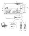
図1は、実施形態のドアロックシステムを含むセキュリティシステムの概要を説明するための図である。
【0036】
家の玄関ドア1には、電子鍵カードと通信を行なうドアロック装置2が取り付けられている。室内には、セキュリティシステムを構成する監視制御装置3が設けられ、ドアロック装置2と接続されている。ドアロック装置2と監視制御装置3とは、この例では接続線により接続されるが、無線により接続するようにしてもよい。
【0037】
監視制御装置3は、ドアロック装置2からの鍵情報を受け取って、前述した鍵情報の認証を行なう装置となることもできる。この例では、鍵情報の認証は、ドアロック装置2において行なうようにされている。
【0038】
そして、この例では、室内には、火災発生を検知する火災センサ4と、ガス漏れを検知するガスセンサ5と、窓の戸締りを検知する窓センサ6a,6bと、テレビ受像機(モニター受像機)7が設けられ、それぞれ監視制御装置3に接続されている。監視制御装置3とそれらとの接続も、接続線により接続されているが、無線により接続してもよい。
【0039】
また、図1では省略したが、火災センサ4で火災発生を検知したときに、その発生現場近傍を撮影できるような位置や、窓センサ6a,6bで賊の侵入を検知したときに、その賊を撮影できるような位置には、監視カメラを設けるようにすることができる。その場合には、それら監視カメラは監視制御装置3に接続され、監視カメラの撮影画像が監視制御装置3に供給されるようにされる。
【0040】
監視制御装置3は、また、電話回線8を通じ、通信ネットワーク9を通じてセキュリティシステムの管理会社が運営する管理サーバ10に接続される。この管理サーバ10も、ドアロック装置2からの鍵情報を、監視制御装置3を介して受け取ることにより、鍵情報の認証を行なう装置となることもできる。
【0041】
通信ネットワーク9は、携帯電話網をも含み、後述するように、監視制御装置3は、異常状態の発生時に、予め、当該監視制御装置3に連絡先としてその電話番号や電子メールアドレスが登録された携帯電話端末11a,11bに、当該異常状態の発生を知らせることが可能とされている。さらに、通信ネットワーク9は、インターネットを含み、パーソナルコンピュータ12は、管理サーバ10に対して当該インターネットを通じてアクセスすることが可能とされている。また、携帯電話端末11a,11bからも、管理サーバ10にアクセスすることが可能とされている。
【0042】
次に、ドアロック装置2の具体的構成例およびその動作、また、監視制御装置3の具体的構成例およびその動作について、詳細に説明する。なお、以下に説明する例では、鍵情報の認証は、ドアロック装置自身が行なうものとする。
【0043】
[ドアロック装置の構成]
図2(A)および図2(B)は、ドアロック装置2の構成例を説明するための図である。図2(A)は、家の外側から玄関ドア1のドアロック装置2の取り付け部分近傍を見た図である。また、図2(B)は、玄関ドア1のドアロック装置2の取り付け部分近傍を、玄関ドア1の端面側から見た図である。
【0044】
この例のドアロック装置2においては、玄関ドア1の外側(戸外側)には、電子鍵カードと通信を行なうための外側電子鍵リーダ/ライタ部21exと、電子鍵カードの認証結果や玄関ドア1の施錠または開錠を視覚的に知らせるための表示素子の例としての外側LED(Light Emitting Diode;発光ダイオード)22exと、電子鍵カードの認証結果や玄関ドア1の施錠または開錠を音声により知らせるための外側スピーカ23exと、外側ドアノブ24exとが設けられている。
【0045】
また、玄関ドア1の内側(屋内側)にも、電子鍵カードと通信を行なうための内側電子鍵リーダ/ライタ部21inと、電子鍵カードの認証結果や玄関ドア1の施錠または開錠を視覚的に知らせるための表示素子の例としての内側LED22inと、電子鍵カードの認証結果や玄関ドア1の施錠または開錠を音声により知らせるための内側スピーカ23inと、内側ドアノブ24inとが設けられている。
【0046】
玄関ドア1には、さらに、玄関ドア係止片25と、ロック片26と、ドア開閉センサ27が設けられている。さらに、玄関ドア1の内側には、ドアロック装置2の動作を制御するためのドアロック制御装置100が設けられており、電子鍵リーダ/ライタ部21exおよび21in、LED22exおよび22in、スピーカ23exおよび23in、ドア開閉センサ27および図示を省略したドアロック機構駆動部が、このドアロック制御装置100に接続されている。
【0047】
玄関ドア係止片25は、ドアノブ24exあるいはドアノブ24inの操作に応じて、玄関ドアの端面1aに垂直な方向に摺動移動する部材である。これは、後述するオートロックモードでない場合において、玄関ドア1が施錠されていないときにも、玄関ドア1の端面1aと対向する壁の端面側に設けられる凹部に勘合して、玄関ドア1を、係止するためのものである。
【0048】
ロック片26は、ドアロック機構の一部を構成する部材であり、図2では図示を省略したドアロック機構駆動部によりドアロック機構が駆動されることにより、玄関ドアの端面1aに垂直な方向に摺動移動して、玄関ドア1を施錠するときには、図2のように、玄関ドア1の端面1aから突出する状態に固定され、玄関ドア1を開錠するときには、玄関ドア1の端面1aから突出しない状態に固定される。
【0049】
なお、図示は省略したが、玄関ドア1の端面1aと対向する壁の端面には、このロック片26が突出した状態のときに嵌合される凹部が形成されており、ロック片26が当該凹部に嵌合される状態が玄関ドアの施錠状態となる。そして、ロック片26が玄関ドア1側に引っ込んで、当該凹部に嵌合していないときには、施錠状態が解除されて、開錠状態になる。
【0050】
玄関ドア開閉センサ27は、例えば光学式センサが用いられ、玄関ドア1が開けられたときは外部光を検知することにより、それを検知し、玄関ドア1が閉じられたときには、玄関ドア1の端面1aが、壁の端面と衝合することにより外部光が遮断されることを検知することにより、それを検知して、玄関ドア1の開閉を検知する。
【0051】
[ドアロック制御装置100の説明]
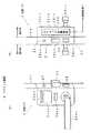
次に、ドアロック制御装置100を中心にしたドアロック装置2の電気的な構成例を図3に示す。
【0052】
すなわち、ドアロック制御装置100は、マイクロコンピュータの構成を備えており、CPU(Central Processing Unit)101に対してシステムバス102を介してプログラムやデータが記録されているROM(Read Only Memory)103と、ワークエリア用RAM(Random Access Memory)104と、鍵情報となる個人IDが記憶されている家族情報メモリ120と、監視制御装置3と通信を行なうための通信インターフェース121とが接続されている。
【0053】
家族情報メモリ120には、予め玄関ドア1の開閉を行なう住人のそれぞれが所持する電子鍵カードに記憶されている個人IDが、電子鍵情報として登録されて格納されている。また、各家族構成員(または住人)の年齢、性別、続き柄、その他の個人情報も、併せて家族情報メモリ120には、格納されている。後述する監視制御装置3の家族情報メモリ205も同様である。電子鍵情報の登録に関しては、後述する。
【0054】
また、システムバス102には、インターフェース105および106を介して内側電子鍵リード/ライト部21inおよび外側電子鍵リード/ライト部21exが接続され、また、内側LED駆動部107を介して内側LED22inが接続され、外側LED駆動部108を介して外側LED22exが接続され、さらに、音声出力インターフェース109を介して内側スピーカ23inが接続され、音声インターフェース110を介して外側スピーカ23exが接続される。
【0055】
さらに、システムバス102には、インターフェース111を介してドア開閉センサ27が接続されると共に、ドアロック機構駆動部112を介して、ロック片26を摺動駆動させるドアロック機構28が接続される。
【0056】
電子鍵リード/ライト部21exまたは21inは、電子鍵カード40と通信を行なう通信部を構成する。電子鍵リード/ライト部21exまたは21inは、この例では、電磁誘導アンテナおよび情報送受信部を含む。
【0057】
この例のドアロック制御装置100は、ドアロック制御モードとして、オートロックモードと、逐次ロックモードとの2通りの制御モードを備えている。
【0058】
オートロックモードは、ドアロック制御装置100が、電子鍵リード/ライト部21ex,21inを介して電子鍵カードと通信することに基づき玄関ドア1を開錠した後、所定時間後に自動的に玄関ドアを施錠状態にするモードである。オートロックモードにおいては、常に、内側と外側の電子鍵リード/ライト部21ex,21inの両方を用いるものとなる。
【0059】
また、逐次ロックモードは、少なくとも玄関ドア1の外側の電子鍵リード/ライト部21exを通じて電子鍵カードと通信することに基づき玄関ドアの施錠、開錠の状態を、そのときの状態とは逆の状態にするモードである。この逐次ロックモードにおいても、内側と外側の電子鍵リード/ライト部21ex,21inの両方を用いることができるが、内側は、別途のマニュアルの施錠手段により施錠するようにした場合には、外側の電子鍵リード/ライト部21exを通じた電子鍵カードとの通信のみにより、玄関ドアの施錠、開錠動作を行なわせるようにすることができる。この逐次ロックモードは、従来からの一般的な鍵による施錠、開錠の方法に合わせたモードである。
【0060】
ドアロック装置2のドアロック制御モードをオートロックモードとするか、逐次ロックモードとするかの選択設定は、この例では、例えば、ドアロック装置2を取り付ける際に、後述するように、作業者により監視制御装置3を通じて行なわれる。
【0061】
ドアロック装置2がいずれのドアロック制御モードに設定されているかの情報は、ドアロック制御装置100内の図示を省略した不揮発性メモリに格納されており、ドアロック制御装置100は、当該不揮発性メモリの記憶情報を参照することにより、自装置のドアロック制御モードが、オートロックモードか、逐次ロックモードかを認識するものである。監視制御装置3を通じたドアロック制御モードの設定動作に関しては、後述する。
【0062】
なお、ドアロック装置2のドアロック制御モードをオートロックモードとするか、逐次ロックモードとするかの選択設定は、監視制御装置3を通じて行なうのではなく、ドアロック装置2に直接的に行なうようにすることもできる。例えば、予め、ドアロック装置2の出荷時に、いずれのドアロック制御モードにするかの設定をドアロック装置2に行なっておくようにしても良い。また、ドアロック装置2に、ドアロック装置2の設置作業者が操作可能な入力操作手段、例えばディップスイッチ等を設けておき、当該入力操作手段を通じて、ドアロック制御モードの設定を行なうようにしてもよい。
【0063】
[電子鍵装置の構成例]
電子鍵装置としては、ICカードからなる電子鍵カード40の他、携帯電話端末やPDA(Personal Digital Assistant)なども用いることができる。この例では、電子鍵装置は、電子鍵情報用の制御用ICチップと通信手段とを備える点では共通している。
【0064】
図4は、電子鍵装置が、ICカードからなる電子鍵カード40である場合の構成例を示す図である。図4(A)は、電子鍵カード40の表面を示し、この表面には、所有者の氏名と、ID番号が表示されている。また、図4(B)は、電子鍵カード40の内部構成例を示しており、電子鍵カード40内には、電子鍵リード/ライト部と通信を行なうための電磁誘導用のアンテナ41と、制御用IC42とが内蔵されている。
【0065】
制御用IC42内には、メモリを含み、電子鍵情報となる識別情報、所有者の氏名、個人IDの他、所有者のその他の必要な個人情報が記憶されている。この個人情報は、父親、母親、子供などの区別が可能なように構成されている。また、制御用IC42内のメモリに、各所有者が行った電子鍵リード/ライト部21exまたは21inとの通信の時刻や履歴(内側と外側のどちらの電子鍵リード/ライト部と通信したか情報を含む)や、各所有者の外出、帰宅の履歴などを書き込むようにされている。
【0066】
なお、これらの履歴情報は、ドアロック制御装置100の家族情報メモリ120や監視制御装置3の後述の家族情報メモリ205における各人に対応するエリアにも記憶されるものである。
【0067】
図5は、電子鍵カード40の内部ブロック構成を示すものである。CPU401に対してシステムバス402を介してプログラムやデータが記録されているROM403と、ワークエリア用RAM404と、電子鍵情報となる識別情報が記憶されている識別情報メモリ405と、通信履歴メモリ406と、送受信インターフェース407とが接続されている。識別情報メモリ405には、使用者の個人情報をも記憶することが可能である。
【0068】
送受信インターフェース407には、電磁誘導アンテナ41に接続されている情報送受信回路408が接続されている。そして、識別情報メモリ405から読み出した識別情報を送受信インターフェース407、情報送受信回路408および電磁誘導アンテナ41を通じて送出する。
【0069】
また、電磁誘導アンテナ41にて受信した情報を、情報送受信回路408および送受信インターフェース407を通じて取り込み、通信履歴メモリ406に書き込んだりする。
【0070】
[監視制御装置3の外観の説明]
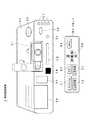
図6は、室内に設けられるセキュリティシステム用の監視制御装置3の構成を説明するための外観図であり、この監視制御装置3は、例えば赤外線や電波を用いたリモートコマンダ50によりリモコン制御可能の構成とされている。
【0071】
監視制御装置3の筐体30には、ビデオカメラ31が組み込まれている。このビデオカメラ31は、この例では、実線位置の横置き状態と、点線位置の縦置き状態とのいずれの状態をも取れる機構により、筐体30に対して取り付けられている。このビデオカメラ31は、セキュリティモードがオンとされたときに、監視制御装置3からの指示により撮影を開始するようにされている。
【0072】
また、ビデオカメラ31による撮影方向は、ビデオカメラが首振り方向に調整可能な構造とされているので、その調整により変えられるようにされている。したがって、使用者は、セキュリティモードオンに先立ち、ビデオカメラ31による撮影方向の調整を行なっておくことができる。
【0073】
そして、筐体30には、ビデオカメラ31による撮影対象部を明るく照明するための撮影用ランプ32が設けられている。また、筐体30には、例えば遠赤外線を検知することにより人を検知する人感センサ33が設けられている。監視制御装置3は、後述するように、セキュリティモードオンのときに人感センサ33で人を検知したときには、賊の侵入であるとして検知し、撮影用ランプ32をオンにすると共に、所定の通報先に撮影画像を送るようにする。
【0074】
筐体30には、また、マイクロホン34とスピーカ35とが設けられている。マイクロホン34は、賊の声や賊侵入時の室内の臨場音を収音するためのものである。スピーカ35は、侵入してきた賊を威嚇する音声を放音するためなどに用いられる。
【0075】
筐体30には、また、電子鍵リード/ライト部36が設けられる。この電子鍵リード/ライト部36は、前述した電子鍵情報としての個人IDの登録の際に用いられるほか、この例では、伝言の記録、再生の際にも用いられる。すなわち、この例においては、監視制御装置3は、伝言装置の役割もできるように構成されており、電子鍵リード/ライト部36により、電子鍵カード40を読み取らせた後、後述するようにリモートコマンダ50の伝言記録ボタンを押すと、設定した相手(家族の誰か)に伝言が残すことができ、また、リモートコマンダ50の伝言再生ボタンを押すと、自分宛ての伝言を再生することができるようになっている。
【0076】
この伝言が記録されているかどうかなどを知らせるため等の用途として、筐体30には、複数個のLED37が設けられている。また、筐体30には、さらに、リモートコマンダ50からのリモコン信号の受信部38が設けられる。
【0077】
また、図6では図示を省略したが、監視制御装置3の背面パネルには、テレビ受像機7のビデオ入力端子に接続される映像出力端子が設けられている。そして、監視制御装置3には、テレビ受像機7の電源のオン・オフなどを制御するためのリモコン送信部39が設けられている。
【0078】
さらに、監視制御装置3は、火災センサ4、ガスセンサ5、窓センサ6a,6b、さらには、監視カメラを接続するためのセンサハブを備えている。また、図1で説明したように、監視制御装置3は、電話回線を通じて、セキュリティシステムの管理会社が運営する管理サーバ10にアクセスできるように構成されている。
【0079】
[監視制御装置3の構成例]
監視制御装置3の内部構成および監視制御装置3と周辺機器との接続状態の構成例を図7に示す。
【0080】
監視制御装置3は、マイクロコンピュータの構成を備えており、CPU201に対して、システムバス202を介して、プログラムやデータが記録されているROM(Read Only Memory)203と、ワークエリア用RAM(Random Access Memory)204と、ドアロック制御装置100の家族情報メモリ120と同様に、電子鍵カード40を所有する家族全員の鍵情報となる個人IDが記憶されている家族情報メモリ205と、ドアロック制御装置100と通信を行なうためのドアロック装置通信インターフェース206と、センサハブ207と、ビデオカメラ31の撮影画像およびマイクロホン34で収音した音声を記憶するための画像・音声メモリ208と、電話回線を通じて管理サーバ10等を通信を行なうための通信インターフェース209とが接続されている。
【0081】
また、システムバス202には、カメラインターフェース210を介してビデオカメラ31が、インターフェース211を介して撮影用ランプ32の照明機構320が、インターフェース212を介して人感センサ33が、インターフェース214を介して電子鍵リード/ライト部36が、インターフェース215を介してリモコン受信部38が、インターフェース216を介してリモコン送信部39が、音声入力インターフェース218を介してマイクロホン34が、インターフェース219を介してLED37が、音声出力インターフェース220を介してスピーカ35が、それぞれ接続されている。
【0082】
さらに、システムバス202は、ビデオ信号出力端子からなるテレビインターフェース217を介してテレビ受像機7に接続されている。また、システムバス202には、時計回路221と、通知連絡設定メモリ222とが接続されている。
【0083】
家族情報メモリ205は、例えばEEPROM(Electronic Erasable Programmable ROM)で構成される。家族情報メモリ205には、ドアロック制御装置100の家族情報メモリ120と同一の複数個の個人ID(電子鍵情報となる識別情報)が格納されている。また、この家族情報メモリ205には、家族構成員のそれぞれについての個人情報や監視制御装置3が玄関ドア1を通じての家族の入退出を管理するための入退出履歴、現在の在宅者の情報も格納される。個人情報としては、例えば氏名、年齢、続き柄、電話番号(携帯電話の電話番号等、連絡先の電話番号となる場合がある)等が格納される。
【0084】
この例の入退出履歴情報には、外出時刻、帰宅時刻が記憶されるほか、外出中であるか、在宅であるかの在/不在フラグが含まれる。この入退出履歴情報は、監視制御装置3が玄関ドア1を通じての家族の入退出を管理するために用いられる。
【0085】
さらに、この例では、この家族情報メモリ205には、セキュリティモード用の情報も格納されている。すなわち、この例では、監視制御装置3では、家族構成員の在宅状況に応じて、セキュリティレベルを変更することが可能なように構成されている。図8は、セキュリティレベルと家族構成員の在宅状況との関係を示すテーブルである。また、図9は、セキュリティレベルとセキュリティ内容との対応を示すテーブルである。
【0086】
図9に示すように、この例においては、セキュリティレベルは、セキュリティレベルが高い方から順に、レベルA、レベルB、レベルC、レベルDまであり、レベルAにおいては、窓および玄関ドアの監視、火災やガス漏れの監視、ビデオカメラ31による監視の全てを行ない、レベルBでは、ビデオカメラ31による監視は行なわずに、窓および玄関ドアの監視および火災やガス漏れの監視を行ない、レベルCでは、火災やガス漏れの監視のみを行ない、レベルDでは、監視を行なわない、という内容である。
【0087】
そして、図8に示すように、家族構成員の在宅状況のそれぞれに対して各セキュリティレベルが割り付けられる。すなわち、この例では、父親が在宅の状況では、監視を行なわないレベルDとされる。また、父親が不在であるが母親が在宅の状況では、火災やガス漏れの監視のみを行なうレベルCとされる。また、子供のみが在宅の状況では、窓および玄関ドアの監視および火災やガス漏れの監視を行なうレベルBとされる。そして、全員が不在である状況では、全ての監視を行なうレベルAとされる。
【0088】
監視制御装置3では、セキュリティモードをオンにするとき、また、セキュリティレベルを変更するとき、これら図8、図9のテーブルを参照し、在宅状況に応じてセキュリティレベルを決定するようにする。
【0089】
図8のセキュリティレベルと、家族構成員の在宅状況との関係は、予め設定しておくこともできるし、使用者が、例えばリモートコマンダ50を用いて監視制御装置3に入力設定することにより、設定を変更することできるように構成されている。
【0090】
なお、これら図8、図9のテーブル情報は、家族情報メモリ205ではなく、別のメモリに格納するようにしても良いことは言うまでもない。
【0091】
ドアロック装置通信インターフェース206は、ドアロック制御装置100に接続されている。センサハブ207には、火災センサ4、ガスセンサ5、窓センサ6a,6bおよび1個あるいは複数個の監視カメラ13が接続される。
【0092】
画像・音声メモリ208は、セキュリティモードがオンであるときに、ビデオカメラ31で撮影した画像情報と、マイクロホン34で収音した音声情報とをバッファリングする監視情報領域と、伝言として記録されている画像情報および音声情報を記憶する伝言情報領域とを備えている。また、監視情報領域には、監視カメラ13用の画像記憶領域も設けられている。
【0093】
監視情報領域は、この例では、所定時間、例えば30秒分の画像情報および音声情報を、いわゆるリングバッファ形式で記憶する。なお、監視情報領域と伝言情報領域とは、別々のメモリの構成とすることも勿論できる。
【0094】
通信インターフェース209は、この例では、ルータ61に接続されている。ルータ61は、ADSLモデム62、スプリッタ63を通じて電話回線65に接続されている。スプリッタ63には、電話端末64が接続される。
【0095】
時計回路221は、現在時刻の情報をシステムバス202に送出する。現在時刻の情報には、年、月、日、曜日などのいわゆるカレンダー情報も含む。
【0096】
通知連絡設定メモリ222は、使用者により、例えばリモートコマンダ50が用いられて設定された通知連絡先の携帯電話番号や電子メールアドレスなどの設定情報を記憶する。CPU201は、センサハブ207からの情報に基づき異常を検知したときに、この設定情報に基づいて、設定された通知連絡先と監視制御装置との間で通信路(通話路)を形成し、通知連絡先に対して異常発生の連絡を行なうようにする。
【0097】
[リモートコマンダ50の説明]
監視制御装置3用のリモートコマンダ50は、図7に示すように、セキュリティボタン51と、オフボタン52と、伝言記録ボタン53と、伝言再生ボタン54と、メニューボタン55と、上下左右の選択を行なう4個のキーとその中央の決定キーとからなるカーソルボタン56とを備えて構成されている。
【0098】
メニュー項目としては、この例では、管理サーバ10に対する電子鍵情報としての個人IDの登録、ドアロック装置2のドアロック制御モードの設定、通知連絡先の設定登録、その他が、用意されており、それぞれのメニュー項目に対応する処理を実行するアプリケーションプログラムは、監視制御装置3のROM203に格納されている。
【0099】
次に、以上のような構成のドアロックシステムの種々の動作について、以下に説明する。
【0100】
[電子鍵カード40の電子鍵情報の登録]
この電子鍵情報としての個人IDの登録が簡単にできることはセキュリティの点で好ましくないので、この例では、この電子鍵情報としての個人IDの登録は、次のようにセキュリティを重視した方法により、例えばドアロック装置2の販売業者あるいは設置業者もしくは使用者により行なわれる。
【0101】
先ず、電子鍵リード/ライト部を備えるパーソナルコンピュータを用意する。このパーソナルコンピュータからインターネットを通じて管理サーバ10のホームページにアクセスし、予め定められたパスワードを入力して、電子鍵情報としての個人ID登録のページにアクセスし、ドアロック装置2のシリアル番号、ドアロック装置2が設置された住所、電話番号、ドアロック装置2の利用者の氏名など、必要な事項を入力する。
【0102】
そして、当該電子鍵情報の登録のページにアクセス中において、登録ボタンをクリックすると、パーソナルコンピュータは、登録したい電子鍵カード40から電子鍵リード/ライト部により個人IDを含む個人情報を読み取って、管理サーバ10に送る。
【0103】
すると、管理サーバ10では、受け取った個人情報中の個人IDを、前記入力されたシリアル番号のドアロック装置2についての電子鍵情報として登録する。そして、管理サーバ10は、登録した電子鍵情報としての個人IDを含む個人情報を、通信ネットワーク9を通じて監視制御装置3に送信する。
【0104】
監視制御装置3は、受け取った個人IDを含む個人情報を、家族情報メモリ205に書き込むと共に、ドアロック制御装置100にも、転送する。ドアロック制御装置100は、受け取った個人IDを含む個人情報を家族情報メモリ120に、電子鍵情報として書き込む。
【0105】
なお、以上の電子鍵情報としての個人IDの登録動作は一例であって、例えば監視制御装置3を通じて同様にして管理サーバ10にアクセスして、登録するようにしても良い。また、管理サーバ10を介することなく、監視制御装置3およびドアロック制御装置100に、電子鍵情報としての個人IDを登録することができるようにしても良い。
【0106】
[監視制御装置3における伝言記録および伝言再生;図10]
前述したように、この例の監視制御装置3は、電子鍵カード40と、リモートコマンダ50を用いて、特定の家人を指定して、伝言を記録しておくことができる。伝言が監視制御装置3に記録されているときには、LED37が点灯あるいは点滅して、その旨を知らせるようにしている。
【0107】
そして、監視制御装置3に、伝言が記録されている場合には、帰宅した家人が、自分の電子鍵カード40を、この電子鍵リード/ライト部36により読み取らせ、リモートコマンダ50により伝言再生を指示すると、記録されている伝言が、その人宛ての伝言である場合には、監視制御装置3は、記録されている伝言を、テレビ受像機7やスピーカ35を通じて再生するようにするように構成されている。
【0108】
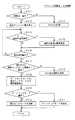
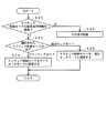
図10は、この伝言記録および再生のための監視制御装置3の処理を説明するためのフローチャートである。この図10の各ステップSの処理は、CPU201がROM203に記憶されているプログラムにしたがって実行されるものである。
【0109】
すなわち、まず、使用者は、伝言記録または伝言再生をするには、自分の電子鍵カード40を電子鍵リード/ライト部36にかざして、通信を行なうようにする。CPU201は、電子鍵リード/ライト部36で電子鍵カード40と通信が行なわれたか否か判別し(ステップS1)、通信が行われたと判別すると、個人IDを認識する(ステップS2)。
【0110】
次に、リモートコマンダ50からのリモコン信号の到来を待ち(ステップS3)、リモコン信号を受信したことを確認したら、そのリモコン信号は、伝言記録ボタン53の操作によるものか否か判別し(ステップS4)、伝言記録ボタン53の操作によるものであると判別したときには、CPU201は、伝言記録動作を行なうようにする(ステップS12)。
【0111】
この伝言記録動作においては、監視制御装置3は、ビデオカメラ31で撮影された伝言者の画像情報をカメラインターフェース210を介して取り込み、画像・音声メモリ208の伝言記録領域に格納すると共に、マイクロホン34で収音した伝言音声情報(伝言メッセージ)をインターフェース218を通じて取り込み、画像・音声メモリ208の伝言記録領域に格納する。このとき、それら画像情報および音声情報は、電子鍵カード40から読み込んだ個人IDに対応付けられて、当該個人IDと共に画像・音声メモリ208に格納される。
【0112】
次に、CPU201は、家族情報メモリ208に記憶されている家族の個人IDを参照して、伝言記録をしようとしている操作者以外の伝言相手のリストをテレビ受像機7の画面に表示する(ステップS14)。このとき、テレビ受像機7に電源が投入されていないときには、リモコン送信部38を通じて電源をオンにするリモコン信号をテレビ受像機7に供給して、テレビ受像機7に電源を投入しておく。なお、伝言相手のリストの画面は、例えばスーパーインポーズによりテレビ番組の画像に重ねて表示するようにしてもよいし、テレビ番組の画像に重ねることなく単独の画面としてもよい。
【0113】
操作者は、この伝言相手のリストから、リモートコマンダ50のカーソルキー56を用いて、伝言相手の選択入力を行ない、カーソルキー56中の中央の決定キーを押す。監視制御装置3のCPU201は、この伝言相手の選択入力を受信して(ステップS15)、当該伝言相手の情報を、画像・音声メモリ208の伝言記録領域の、前記画像情報および伝言音声メッセージに対応させて格納して登録する(ステップS16)。そして、伝言が記録されたことを報知するために、1個のLED37を点灯させる(ステップS17)。LED37は、図6に示したように複数個設けられており、記録されている伝言の数だけ、点灯することとなる。
【0114】
また、ステップS4において、リモコン信号が伝言記録ボタン53の操作によるものではないと判別したときには、伝言再生ボタン54の操作によるものであるか否か判別する(ステップS5)。伝言再生ボタン54の操作によるものでないと判別したときには、CPU201は、当該操作されたボタンに応じた処理を行なう(ステップS6)。
【0115】
そして、ステップS5において、伝言再生ボタン54の操作によるものであると判別したときには、CPU21は、ステップS2で認識した個人IDを検索子として、画像・音声メモリ208の伝言記録領域の記憶内容を検索して、電子鍵カード40を電子鍵リード/ライト部36にかざした操作者宛ての伝言があるか否か判別する(ステップS7)。
【0116】
そして、ステップS7において、操作者宛ての伝言が無いと判別したときには、CPU201は、例えば予めROM203に用意されている「伝言はありません」の文字情報をテレビ受像機7の画面に表示すると共に、スピーカ35を通じて音声として放音して、操作者に報知する(ステップS8)。
【0117】
また、ステップS7において、操作者宛ての伝言が有ると判別したときには、当該操作者宛ての伝言画像および伝言音声を画像・音声メモリ208から読み出して、テレビ受像機7に表示すると共に、スピーカ35から放音して再生する(ステップS9)。
【0118】
伝言の再生が終了すると、CPU201は、テレビ受像機7の画面に伝言を消去するかどうかの問い合わせを表示するので、操作者は、その表示画面に含まれる「YES」、「NO」のいずれかをリモートコマンダ50のカーソルキー56を用いて選択する。CPU201は、当該操作者の選択入力から、伝言を消去するか否か判別し(ステップS10)、消去すると判別したときには、画像・音声メモリ208の対応する画像・音声情報を消去し(ステップS11)、点灯しているLED37の一つを消灯する(ステップS12)。そして、この伝言記録再生処理ルーチンを終了する。
【0119】
また、ステップS10で、伝言を消去しないと判別したときには、そのまま、この伝言記録再生処理ルーチンを終了する。
【0120】
[ドアロック制御モードの選択設定;図11、図12]
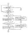
前述したように、この実施形態では、監視制御装置3を通じてドアロック制御モードの設定ができるようにされているので、その設定動作を、図11のフローチャートを参照しながら説明する。
【0121】
先ず、監視制御装置3のCPU201は、リモコン受信部38の受信信号を監視して、ドアロック制御モードの設定を含む設定メニューのための特定のボタン操作がなされたか否か判別する(ステップS21)。この例では、この特定のボタン操作としては、通常の使用者が行なわない操作とされており、例えばセキュリティボタン51とメニューボタン55との同時操作などとされている。このような特定のボタン操作は、ドアロック装置2の設置業者等が設定作業を行なうために定義されている。
【0122】
ステップS21で、前記の特定のボタン操作はされないと判別されたときには、単独のボタン操作に応じた処理などの、その他の処理を行なう(ステップS22)。また、ステップS21で、前記の特定のボタン操作がされたと判別されたときには、設定メニューの一覧をテレビ受像機7の画面に、前述の伝言記録再生の場合と同様にして表示するようにする(ステップS23)。
【0123】
この設定メニューの一覧表示に対しては、操作者は、行ないたい設定メニュー項目の選択をリモートコマンダ50のカーソルキーを用いて行なう。CPU201は、リモコン受信部38の受信信号を監視してメニュー項目の選択操作がなされたか否か判別し(ステップS24)、メニュー項目の選択操作がなされたと判別したときには、例えば反転表示して示す選択中項目を、選択操作に応じて変更する(ステップS25)。そして、設定項目の決定操作がなされたか否か判別する(ステップS26)。また、ステップS24で、メニュー項目の選択操作がなされないと判別したときには、即座にステップS26に進んで設定項目の決定操作がなされたか否か判別する。
【0124】
ステップS26で、設定項目の決定操作がなされないと判別したときには、ステップS24に戻る。また、ステップS26で、設定項目の決定操作がなされたと判別したときには、選択された設定項目はドアロック制御モードの設定であるか否か判別し(ステップS27)、そうではなかったときには選択された他の設定項目についての処理ルーチンを実行する(ステップS28)。
【0125】
ステップS27で、選択された設定項目はドアロック制御モードの設定であると判別したときには、CPU201は、テレビ受像機7の画面にオートロックモードと、逐次ロックモードとの選択画面を表示する(ステップS29)。操作者は、この選択画面において、いずれかの選択入力をカーソルキー56を用いて行なう。
【0126】
そこで、CPU201は、リモコン受信部38を監視して、オートロックモードが選択されたか否か判別し(ステップS30)、オートロックモードが選択されたと判別したときには、ドアロック装置2をオートロックモードに設定する設定動作を行なう(ステップS31)。
【0127】
すなわち、CPU201は、監視制御装置3に内蔵の不揮発性メモリ部のドアロック装置2のドアロック制御モードの記憶領域に、オートロックモードであることを示す情報を記憶すると共に、オートロックモードにする旨の指示をドアロック装置2に対して、ドアロック装置通信インターフェース206を通じて送る。
【0128】
また、ステップS30で、オートロックモードではないと判別したときには、CPU201は、逐次ロックモードが選択されたと判別して、ドアロック装置2を逐次ロックモードにする設定動作を行なう(ステップS32)。
【0129】
すなわち、CPU201は、監視制御装置3に内蔵の不揮発性メモリ部のドアロック装置2のドアロック制御モードの記憶領域に、逐次ロックモードであることを示す情報を記憶すると共に、逐次ロックモードにする旨の指示をドアロック装置2に対して、ドアロック装置通信インターフェース206を通じて送る。
【0130】
以上で、監視制御装置3におけるロック制御モードの設定時の動作は終了となる。
【0131】
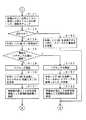
次に、ドアロック装置通信インターフェース206を通じて送られてきたドアロック制御モードの指示情報を受信したドアロック制御装置100の動作について、図12のフローチャートを参照して説明する。
【0132】
先ず、ドアロック制御装置100のCPU101は、ドアロック制御モードの設定指示情報を監視制御装置3から受け取ったか否か判別し(ステップS41)、受け取らないときには、その他の処理を行なう(ステップS42)。
【0133】
ステップS41で、ドアロック制御モードの設定指示情報を監視制御装置3から受け取ったと判別したときには、CPU101は、選択指示されたドアロック制御モードは、オートロックモードと逐次ロックモードのいずれであるか判別する(ステップS43)。
【0134】
ステップS43で、選択指示されたドアロック制御モードはオートロックモードであると判別したときには、CPU101は、ドアロック装置2のドアロック制御モードをオートロックモードに設定する処理を行なう(ステップS44)。
【0135】
すなわち、ステップS44においては、ドアロック制御装置100のCPU101は、オートロックモードの設定指示に基づき、ドアロック装置2の内側電子鍵リード/ライト部21inと、外側電子鍵リード/ライト部21exとの両方をアクティブにし、かつ、プログラムROM13のドアロック制御のアプリケーションを、オートロックモード用のものとするようにする。そして、CPU101は、ドアロック制御装置100が備える不揮発性メモリ部のドアロック制御モードの記憶領域に、オートロックモードであることを示す情報を記憶する。
【0136】
また、ステップS43で、選択指示されたドアロック制御モードは逐次ロックモードであると判別したときには、CPU101は、ドアロック装置2のドアロック制御モードを逐次ロックモードに設定する処理を行なう(ステップS45)。
【0137】
すなわち、ステップS45においては、ドアロック制御装置100のCPU101は、逐次ロックモードの設定指示に基づき、この例では、ドアロック装置2の内側電子鍵リード/ライト部21inと、外側電子鍵リード/ライト部21exとの両方をアクティブにし、かつ、プログラムROM13のドアロック制御のアプリケーションを、逐次ロックモード用のものとするようにする。そして、CPU101は、ドアロック制御装置100が備える不揮発性メモリ部のドアロック制御モードの記憶領域に、逐次ロックモードであることを示す情報を記憶する。
【0138】
なお、この例では、逐次ロックモードにおいても、内側電子鍵リード/ライト部21inと、外側電子鍵リード/ライト部21exとの両方を用いるようにしたが、この逐次ロックモードにおいては、外側電子鍵リード/ライト部exのみをアクティブにして、内側電子鍵リード/ライト部21inを用いないようにすることもできる。その場合には、家の内側からの施錠が問題になるが、例えば、内側からの玄関ドアの施錠を、電子鍵カードを用いずにマニュアル操作で行なえる構成とすればよい。
【0139】
次に、オートロックモードと、逐次ロックモードのそれぞれの場合のドアロック装置2の動作について説明する。以下に説明するフローチャートにおける各ステップSの動作は、ドアロック制御装置100のCPU101が主として実行する処理動作である。
【0140】
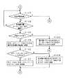
[オートロックモード;図13〜図18]
オートロックモードのときの動作を、図13〜図18のフローチャートを参照しながら説明する。このオートロックモードのときには、玄関ドア1は、定常状態では、施錠状態とされる。そして、電子鍵カード40が、内側電子鍵リード/ライト部21inまたは外側電子鍵リード/ライト部21exにかざされて通信が両者の間で行なわれ、個人IDについての認証がとれたときには、所定時間のみ玄関ドアを開錠し、所定時間後に、自動的に玄関ドア1は施錠状態に戻るように、ドアロック制御装置100により制御されるものである。
【0141】
CPU101は、インターフェース105,106を介して、内側電子鍵リード/ライト部21inおよび外側電子鍵リード/ライト部21exを監視し、電子鍵カード40がかざされて、電子鍵カード40と内側電子鍵リード/ライト部21inまたは外側電子鍵リード/ライト部21exとの間で通信が行われるのを待つ(ステップS51)。
【0142】
そして、ステップS51において、電子鍵カード40がかざされて、電子鍵カード40と通信が行なわれたと判別したときには、CPU101は、個人IDを含む個人情報を電子鍵カード40から受信し、例えばRAM104などに一時的に格納する(ステップS52)。このとき、ドアロック制御装置100が備える時計回路(図示を省略)の時刻情報が、電子鍵カード40に与えられ、制御用IC内42のメモリに書き込まれる。また、内側電子鍵リード/ライト部21inまたは外側電子鍵リード/ライト部21exのどちらと通信をしたかの情報として、通信相手のID等が制御用IC42のメモリに書き込まれる。
【0143】
次に、CPU101は、内側電子鍵リード/ライト部21inまたは外側電子鍵リード/ライト部21exのどちらで電子鍵カード40と通信が行われたかを判別する(ステップS53)。その判別結果と、前記の通信の時刻情報とは、家族情報メモリ120の、前記個人IDに対応する家人の記録エリアにも書き込まれ、また、監視制御装置3にも、その家族情報メモリ205に記憶させるために転送される。
【0144】
[内側電子鍵リード/ライト部21inでの通信の場合;図13〜図15]
ステップS53で、電子鍵カード40と通信が行われたのが内側電子鍵リード/ライト部21inであると判別したときには、CPU101は、在宅者が外出する場合であるとして、以下のような処理を行なう。なお、この例では、在宅者が玄関ドア1を開錠し、玄関ドア1を開けたときには、それまでにセキュリティモードがオンになっていても、一旦、セキュリティモードは、オフとされるものとしている。
【0145】
CPU101は、先ず、家族情報メモリ120に記憶されている個人IDと、電子鍵カード40から受信した個人IDとを比較して、家族情報メモリ120に記憶されている個人IDの中に、電子鍵カード40から受信した個人IDと一致するものがあるかどうかにより、当該電子鍵カード40がドアロック装置2に登録された電子鍵カードであるか否かを判別して、当該電子鍵カード40についての認証を行なう(ステップS54)。
【0146】
そして、その認証結果を判別し(ステップS55)、家族情報メモリ120に記憶されている個人IDの中に、電子鍵カード40から受信した個人IDと一致するものがなくて、認証が取れなかったとき(認証NG)であると判別したときには、CPU101は、内側LED駆動部107を駆動して、内側LED22inを赤色で点滅させると共に、内側スピーカ23inから警告音を放音して、認証NGであることを電子鍵カード40の使用者に報知する(ステップS56)。そして、ドアロック機構28は施錠状態のままとして、ステップS51に戻る。
【0147】
また、ステップS55で、家族情報メモリ120に記憶されている個人IDの中に、電子鍵カード40から受信した個人IDと一致するものがあって、認証がOKであると判別したときには、CPU101は、内側LED駆動部107を駆動して、内側LED22inを緑色で1秒間点灯させ、認証OKであることを電子鍵カード40の使用者に報知する(ステップS57)。このとき、CPU101により、併せて内側スピーカ23inから「認証がとれました」というメッセージを放音させるようにしても良い。
【0148】
そして、このとき、認証がOKであることから、CPU101は、ドアロック機構駆動部112を駆動制御して、ドアロック機構28により玄関ドア1を開錠状態にし(ステップS58)、内側スピーカ23inから、「ドアロックを解除しました」というメッセージを放音させる(ステップS59)。このとき、内側LED22inを、例えば緑色で点滅させ、ドアロックの解除状態を電子鍵カード40の使用者に報知するようにしてもよい。
【0149】
このとき、CPU101は、電子鍵カード40により内側から玄関ドア1が開錠されたことを認識していることに基づき、当該電子鍵カード40の使用者(在宅者)が外出しようとしていると認識する。そして、監視制御装置3に対して窓の開閉状態についての問い合わせを送る(図14のステップS61)。
【0150】
これに対して、監視制御装置3では、窓センサ6a,6bのセンサ出力をセンサハブ207を通じて取得して、窓の開閉を確認する。つまり、戸締りを確認する。そして、窓の開閉状態についての確認結果をドアロック装置インターフェース206を通じてドアロック制御装置100に返信するようにする。
【0151】
ドアロック制御装置100では、この窓の開閉状態についての確認結果を、通信インターフェース121を通じて受信する(ステップS62)。そして、CPU101は、受信した当該確認結果を解析して、窓が開放されているか否か判別する(ステップS63)。
【0152】
そして、窓が開いていると判別したときには、CPU101は、窓が開いていることを内側スピーカ23inからの放音音声により警告する(ステップS64)。また、窓が閉じていると判別したときには、CPU101は、戸締りがOKであることを内側スピーカ23inからの放音音声により報知する(ステップS65)。
【0153】
次に、CPU101は、ドア開閉センサ27のセンサ出力をインターフェース111を通じて取り込み、玄関ドア1が開けられた否か監視する(ステップS66)。そして、CPU101は、玄関ドア1が開けられずに所定時間、例えば10秒経過したかどうかを判別し(ステップS67)、10秒経過したと判別したときには、玄関ドア1を自動的に施錠状態に戻すようにする(ステップS68)。そして、CPU101は、内側LED22inを緑色で点滅して、玄関ドア1が施錠状態に戻ったことを報知する(ステップS69)。
【0154】
また、ステップS66で、ステップS58での開錠後、10秒以内に玄関ドア1が開かれたと判別したときには、CPU101は、ステップS52で取り込んだ個人IDで示される在宅者が外出をしたと認識して、当該個人IDを含む個人情報を、外出者情報として監視制御装置3に転送する(ステップS70)。
【0155】
その後、CPU101は、ドア開閉センサ27のセンサ出力を参照して、玄関ドア1が閉じられたことを確認し(ステップS71)、玄関ドア1が閉じられた後、所定時間、例えば3秒経過したことを確認したら(ステップS72)、ドアロック機構駆動部112を駆動制御して、ドアロック機構28により玄関ドア1を施錠状態に復帰させるようにする(図15のステップS81)。そして、CPU101は、外側LED22exを緑色で点滅して、玄関ドア1が施錠状態に戻ったことを電子鍵カード40の使用者に報知する(ステップS82)。この外側LED22exの緑色点滅は、所定時間、例えば10秒間続けられる。
【0156】
その後、CPU101は、前記所定時間、例えば10秒経過したか否か判別し(ステップS83)、所定時間経過していないと判別したときには、ステップS51で通信が行われたと判別された電子鍵カードが、再度、外側電子鍵リード/ライト部21exと通信したか否か判別する(ステップS84)、通信がなされないと判別したときにはステップS83に戻る。
【0157】
そして、ステップS83で、電子鍵カードと外側電子鍵リード/ライト部21exとで通信が行われずに、前記所定時間経過したと判別したときには、CPU101は、内側電子鍵リード/ライト部21inに対して電子鍵カード40がかざされたことにより開始された玄関ドアのロック制御動作を一段落したとして、図13のステップS51に戻る。
【0158】
また、ステップS84で、玄関ドア施錠復帰後、外側LED22exの緑色点滅が終了する所定時間経過する前に、ステップS51において通信が行われたと判別された電子鍵カードと外側電子鍵リード/ライト部21exとで通信が行われたと判別すると、ステップS61〜S63で確認された戸締りを再確認する(ステップS85)。
【0159】
ステップS85で、戸締りがOKであると判別したときには、CPU101は、通信インターフェース121を通じてセキュリティモードをオンにする要求を監視制御装置3に送信する(ステップS86)。
【0160】
この要求に対しては、監視制御装置3は、そのときの在宅状況をチェックして、セキュリティレベルが図8に示したいずれのレベルとなるかを判定する。そして、監視制御装置3は、その判定の結果、セキュリティレベルがレベルDであるときには、セキュリティモードはオンにできないので、その旨をドアロック制御装置100に返し、セキュリティレベルがレベルD以外であるときには、セキュリティモードをオンにできるので、その旨をドアロック制御装置100に返す。
【0161】
ドアロック制御装置100のCPU101は、監視制御装置3からのセキュリティモードオンの要求に対する返答を解析して、セキュリティモードをオンにできるか否か判別する(ステップS87)。そして、セキュリティモードがオンにできる旨の返答を監視制御装置3から受けたと判別したときには、CPU101は、外側スピーカ23exから、「セキュリティモードをオンにします」というメッセージを放音させる(ステップS88)。
【0162】
また、ステップS87で、セキュリティモードがオンにできない旨の返答を監視制御装置3から受けたと判別したときには、CPU101は、外側スピーカ23exから、「在宅者が存在するため、セキュリティモードをオンにはできません」というメッセージを放音させる(ステップS89)。その後、ステップS51に戻る。
【0163】
また、ステップS85で、窓が開いていて戸締りが完了していないと判別したときには、CPU101は、「窓が開いているため、セキュリティモードをオンにすることはできません」という警告メッセージを放音する(ステップS90)。そして、その後、ステップS51に戻る。
【0164】
[外側電子鍵リード/ライト部21exでの通信の場合;図16〜図18]
ステップS51で、電子鍵カード40と通信が行われたのが外側電子鍵リード/ライト部21exであると判別したときには、CPU101は、家人が帰宅した場合あるいはその他の外にいる者の入室要求であるとして、以下のような処理を行なう。
【0165】
CPU101は、まず、家族情報メモリ120に記憶されている個人IDと、電子鍵カード40から受信した個人IDとを比較して、家族情報メモリ120に記憶されている個人IDの中に、電子鍵カード40から受信した個人IDと一致するものがあるかどうかにより、当該電子鍵カード40がドアロック装置2に登録された電子鍵カードであるか否かを判別して、当該電子鍵カード40についての認証を行なう(図16のステップS101)。
【0166】
そして、その認証結果を判別し(ステップS102)、家族情報メモリ120に記憶されている個人IDの中に、電子鍵カード40から受信した個人IDと一致するものがなくて、認証が取れなかったとき(認証NG)であると判別したときには、CPU101は、外側LED駆動部108を駆動して、外側LED22exを赤色で点滅させると共に、外側スピーカ23exから警告音を放音して、認証NGであることを電子鍵カード40の使用者に報知する(ステップS103)。そして、ドアロック機構28は施錠状態のままとして、図13のステップS51に戻る。
【0167】
また、ステップS102で、家族情報メモリ120に記憶されている個人IDの中に、電子鍵カード40から受信した個人IDと一致するものがあって、認証がOKであると判別したときには、CPU101は、外側LED駆動部108を駆動して、外側LED22exを緑色で1秒間点灯させ、認証OKであることを電子鍵カード40の使用者に報知する(ステップS104)。このとき、CPU101により、合わせて外側スピーカ23exから「認証がとれました」というメッセージを放音させるようにしても良い。
【0168】
そして、このとき、認証がOKであることから、CPU101は、ドアロック機構駆動部112を駆動制御して、ドアロック機構28により玄関ドア1を開錠状態にし(ステップS105)、外側スピーカ23exから、「ドアロックを解除しました」というメッセージを放音させる(ステップS106)。このとき、外側LED22exを、例えば緑色で点滅させ、ドアロックの解除状態を電子鍵カード40の使用者に報知するようにしてもよい。
【0169】
次に、CPU101は、ドア開閉センサ27のセンサ出力をインターフェース111を通じて取り込み、玄関ドア1が開けられた否か監視する(ステップS107)。そして、CPU101は、玄関ドア1が開けられずに所定時間、例えば10秒経過したかどうかを判別し(ステップS108)、10秒経過したと判別したときには、玄関ドア1を自動的に施錠状態に戻すようにする(ステップS109)。そして、CPU101は、外側LED22exを緑色で点滅して、玄関ドア1が施錠状態に戻ったことを報知する(ステップS110)。
【0170】
その後、CPU101は、所定時間、例えば10秒経過したか否か判別し(図17のステップS111)、所定時間経過していないと判別したときには、ステップS51で通信が行われたと判別された電子鍵カード40が外側電子鍵リード/ライト部21exと通信したか否か判別し(ステップS112)、通信がなされないと判別したときにはステップS111に戻る。
【0171】
そして、ステップS111で、電子鍵カード40と外側電子鍵リード/ライト部21exとで通信が行われずに、所定時間経過したと判別したときには、CPU101は、外側電子鍵リード/ライト部21exに対して電子鍵カード40がかざされたことにより開始された玄関ドアのロック制御動作を一段落したとして、図13のステップS51に戻る。
【0172】
また、ステップS112で、玄関ドア施錠復帰後、所定時間経過する前に、ステップS51において通信が行われたと判別された電子鍵カード40と外側電子鍵リード/ライト部21exとで通信が行われたと判別すると、戸締りを確認する(ステップS113)。
【0173】
このステップS113での戸締りの確認は、前述のステップS61〜S63において説明した処理と同様に行なう。つまり、ドアロック制御装置100は、監視制御装置3に対して窓の開閉状態についての問い合わせを行ない、問い合わせ結果を監視制御装置3から取得する。そして、その問い合わせ結果から、戸締りがOKかどうかを判別する。
【0174】
ステップS113で、戸締りがOKであると判別したときには、CPU101は、通信インターフェース121を通じてセキュリティモードをオンにする要求を監視制御装置3に送信する(ステップS114)。
【0175】
この要求に対しては、監視制御装置3は、そのときの在宅状況をチェックして、セキュリティレベルが図8に示したいずれのレベルとなるかを判定する。そして、監視制御装置3は、その判定の結果、セキュリティレベルがレベルDであるときには、セキュリティモードはオンにできないので、その旨をドアロック制御装置100に返し、セキュリティレベルがレベルD以外であるときには、セキュリティモードをオンにできるので、その旨をドアロック制御装置100に返す。
【0176】
ドアロック制御装置100のCPU101は、監視制御装置3からのセキュリティモードオンの要求に対する返答を解析して、セキュリティモードをオンにできるか否か判別する(ステップS115)。そして、セキュリティモードがオンにできる旨の返答を監視制御装置3から受けたと判別したときには、CPU101は、外側スピーカ23exから、「セキュリティモードをオンにします」というメッセージを放音させる(ステップS116)。
【0177】
また、ステップS115で、セキュリティモードがオンにできない旨の返答を監視制御装置3から受けたと判別したときには、CPU101は、外側スピーカ23exから、「在宅者が存在するため、セキュリティモードをオンにはできません」というメッセージを放音させる(ステップS117)。その後、ステップS51に戻る。
【0178】
また、ステップS113で、窓が開いていて戸締りが完了していないと判別したときには、CPU101は、「窓が開いているため、セキュリティモードをオンにすることはできません」という警告メッセージを放音する(ステップS118)。そして、その後、図13のステップS51に戻る。
【0179】
ステップS111〜ステップS118の処理は、一旦、玄関ドア1を内側から開錠した後、所定時間以内に、外側電子鍵リード/ライト部21exに電子鍵カード40をかざして、セキュリティモードをオンにするのを忘れた者が、もう一度、室内に戻って、内側電子鍵リード/ライト部21inに対して電子鍵カード40をかざすところからやり直す手間を防止するための処理である。
【0180】
すなわち、一旦、玄関ドア1を内側から開錠した後、所定時間以内に、外側電子鍵リード/ライト部21exに電子鍵カード40をかざして、セキュリティモードをオンにするのを忘れた、あるいは失敗した場合に、外側電子鍵リード/ライト部21exに電子鍵カード40をかざして、玄関ドア1を一旦開錠させ、その後、10秒待って再施錠になった後、10秒以内に、再び、外側電子鍵リード/ライト部21exに電子鍵カード40をかざすことにより、セキュリティモードをオンにすることができるものである。このようにすれば、セキュリティモードをオンに設定するために、開錠してから室内に入り、内側電子鍵リード/ライト部21inに電子鍵カード40をかざすところからやり直す必要がなく、便利である。
【0181】
次に、ステップS107で、ステップS105でのドアロックの開錠後、10秒以内に玄関ドア1が開かれたと判別したときには、CPU101は、ステップS52で取り込んだ個人IDで示される外出者が帰宅したと認識して、当該個人IDを含む個人情報を、帰宅者情報として監視制御装置3に転送する(図18のステップS121)。
【0182】
その後、CPU101は、ドア開閉センサ27のセンサ出力を参照して、玄関ドア1が閉じられたことを確認し(ステップS122)、玄関ドア1が閉じられた後、所定時間、例えば3秒経過したことを確認したら(ステップS123)、ドアロック機構駆動部112を駆動制御して、ドアロック機構28により玄関ドア1を施錠状態に復帰させるようにする(ステップS124)。そして、CPU101は、内側LED22inを緑色で点滅して、玄関ドア1が施錠状態に戻ったことを報知する(ステップS125)。
【0183】
その後、CPU101は、帰宅者があったことから在宅状況が変更することに基づき、セキュリティレベルの変更指示を監視制御装置3に送る(ステップS126)。
【0184】
このセキュリティレベルの変更指示を受け取った監視制御装置3では、ステップS121での帰宅者情報による在宅状況の変化を認識し、図8に示した在宅状況とセキュリティレベルとの対応テーブルを参照して、セキュリティレベルの変更の必要があるか否か判別し、必要があるときには、セキュリティレベルを変更する。そして、監視制御装置3は、セキュリティレベルを変更したかどうかを、ドアロック制御装置100に通知する。
【0185】
ドアロック制御装置100のCPU101は、監視制御装置3からのセキュリティレベルの変更に関する通知を受け取って(ステップS127)、セキュリティレベルが変更されたか否かを判別する(ステップS128)。
【0186】
そして、ステップS128で、セキュリティモードが変更されたと判別したときには、CPU101は、内側スピーカ23inから、「セキュリティレベルを変更しました」というメッセージを放音する(ステップS129)。そして、ステップS51に戻る。
【0187】
なお、以上の説明では、帰宅者があったときには、ドアロック制御装置100から、ステップS126において、監視制御装置3にセキュリティレベルの変更指示を送るようにしたが、監視制御装置3では、ステップS121での帰宅者情報の転送を受けるので、ドアロック制御装置100からのセキュリティレベルの変更指示を受けなくても、自動的にセキュリティレベルの変更が必要かどうかを判断して、必要である場合には、セキュリティレベルを自動的に変更するようにしても良い。その場合には、セキュリティレベルを変更したときには、その旨をドアロック制御装置100に転送するようにする。
【0188】
[逐次ロックモードの説明;図19〜図21]
次に、逐次ロックモードのときの動作を、図19および図20のフローチャートを参照しながら説明する。この逐次ロックモードのときには、電子鍵カード40が、内側電子鍵リード/ライト部21inまたは外側電子鍵リード/ライト部21exにかざされて通信が両者の間で行なわれ、個人IDについての認証がとれたときには、そのときの玄関ドア1の開錠あるいは施錠の状態とは逆の状態になるように、ドアロック機構28は、ドアロック制御装置100により制御されるものである。
【0189】
CPU101は、インターフェース105,106を介して、内側電子鍵リード/ライト部21inおよび外側電子鍵リード/ライト部21exを監視し、電子鍵カード40がかざされて、電子鍵カード40と内側電子鍵リード/ライト部21inまたは外側電子鍵リード/ライト部21exとの間で通信が行われるのを待つ(ステップS131)。
【0190】
そして、ステップS131において、電子鍵カード40がかざされて、電子鍵カード40と通信が行なわれたと判別したときには、CPU101は、個人IDを含む個人情報を電子鍵カード40から受信し、例えばRAM104などに一時的に格納する(ステップS132)。このとき、前述と同様に、電子鍵カード40には時刻情報等が書き込まれると共に、家族情報メモリ120および監視制御装置3の家族情報メモリ205への時刻情報等の書き込みが行なわれる。
【0191】
内側電子鍵リード/ライト部21inまたは外側電子鍵リード/ライト部21exのどちらで電子鍵カード40と通信が行われたかを判別する(ステップS133)。
【0192】
[内側電子鍵リード/ライト部21inでの通信の場合;図19]
ステップS133で、電子鍵カード40と通信が行われたのが内側電子鍵リード/ライト部21inであると判別したときには、CPU101は、在宅者が外出する場合あるいは玄関ドア1をセキュリティのために施錠する場合であるとして、以下のような処理を行なう。
【0193】
CPU101は、先ず、家族情報メモリ120に記憶されている個人IDと、電子鍵カード40から受信した個人IDとを比較して、家族情報メモリ120に記憶されている個人IDの中に、電子鍵カード40から受信した個人IDと一致するものがあるかどうかにより、当該電子鍵カード40がドアロック装置2に登録された電子鍵カードであるか否かを判別して、当該電子鍵カード40についての認証を行なう(ステップS134)。
【0194】
そして、その認証結果を判別し(ステップS135)、家族情報メモリ120に記憶されている個人IDの中に、電子鍵カード40から受信した個人IDと一致するものがなくて、認証が取れなかったとき(認証NG)であると判別したときには、CPU101は、内側LED駆動部107を駆動して、内側LED22inを赤色で点滅させると共に、内側スピーカ23inから警告音を放音して、認証NGであることを電子鍵カード40の使用者に報知する(ステップS136)。そして、ドアロック機構28は、その前の状態のままとして、ステップS131に戻る。
【0195】
また、ステップS135で、家族情報メモリ120に記憶されている個人IDの中に、電子鍵カード40から受信した個人IDと一致するものがあって、認証がOKであると判別したときには、CPU101は、内側LED駆動部107を駆動して、内側LED22inを緑色で1秒間点灯させ、認証OKであることを電子鍵カード40の使用者に報知する(ステップS137)。このとき、CPU101により、併せて内側スピーカ23inから「認証がとれました」というメッセージを放音させるようにしても良い。
【0196】
そして、CPU101は、現在のドアロック機構28による玄関ドア1のロック状態は、施錠状態になっているか否か判別する(ステップS138)。このステップS138で、ドアロック機構28による玄関ドア1のロック状態が、開錠状態であると判別したときには、その逆の状態である施錠状態にするように、ドアロック機構駆動部112を駆動制御する(ステップS139)。
【0197】
そして、CPU101は、内側LED22inを、例えば緑色で点滅させると共に、内側スピーカ23inから、「玄関ドアを施錠しました」というメッセージを放音させ、施錠状態にしたことを電子鍵カード40の使用者に報知するようにする(ステップS140)。
【0198】
そして、CPU101は、ステップS132で取り込んだ個人IDで示される者が、セキュリティのために施錠をしたと認識して、当該個人IDを含む個人情報を、在宅者情報として監視制御装置3に転送する(ステップS141)。
【0199】
また、ステップS138で、現在のドアロック機構28のロック状態は、施錠状態であると判別したときには、CPU101は、ドアロック機構駆動部112を駆動制御して、ドアロック機構28を開錠状態にし(ステップS142)、内側LED22inを、例えば緑色で点滅させると共に、内側スピーカ23inから、「ドアロックを解除しました」というメッセージを放音させる(ステップS143)。
【0200】
そして、このときには、CPU101は、ステップS132で取り込んだ個人IDで示される者が、開錠をして外出をしたと認識して、当該個人IDを含む個人情報を、外出者情報として監視制御装置3に転送する(ステップS144)。
【0201】
[外側電子鍵リード/ライト部21exでの通信の場合;図20〜図21]
ステップS131で、電子鍵カード40と通信が行われたのが外側電子鍵リード/ライト部21exであると判別したときには、CPU101は、家人が帰宅して開錠する場合あるいは家人が外出のため施錠する場合であるとして、以下のような処理を行なう。
【0202】
CPU101は、まず、家族情報メモリ120に記憶されている個人IDと、電子鍵カード40から受信した個人IDとを比較して、家族情報メモリ120に記憶されている個人IDの中に、電子鍵カード40から受信した個人IDと一致するものがあるかどうかにより、当該電子鍵カード40がドアロック装置2に登録された電子鍵カードであるか否かを判別して、当該電子鍵カード40についての認証を行なう(ステップS151)。
【0203】
そして、その認証結果を判別し(ステップS152)、家族情報メモリ120に記憶されている個人IDの中に、電子鍵カード40から受信した個人IDと一致するものがなくて、認証が取れなかったとき(認証NG)であると判別したときには、CPU101は、外側LED駆動部108を駆動して、外側LED22exを赤色で点滅させると共に、外側スピーカ23exから警告音を放音して、認証NGであることを電子鍵カード40の使用者に報知する(ステップS153)。そして、ドアロック機構28は施錠状態のままとして、ステップS131に戻る。
【0204】
また、ステップS102で、家族情報メモリ120に記憶されている個人IDの中に、電子鍵カード40から受信した個人IDと一致するものがあって、認証がOKであると判別したときには、CPU101は、外側LED駆動部108を駆動して、外側LED22exを緑色で1秒間点灯させ、認証OKであることを電子鍵カード40の使用者に報知する(ステップS154)。このとき、CPU101により、併せて外側スピーカ23exから「認証がとれました」というメッセージを放音させるようにしても良い。
【0205】
そして、CPU101は、現在のドアロック機構28のロック状態は、施錠状態になっているか否か判別する(ステップS155)。このステップS155で、現在のドアロック機構28による玄関ドア1のロック状態は、施錠状態であると判別したときには、CPU101は、ドアロック機構駆動部112を駆動制御して、ドアロック機構28により玄関ドア1を開錠状態にし(ステップS156)、内側LED22inを、例えば緑色で点滅させると共に、内側スピーカ23inから、「ドアロックを解除しました」というメッセージを放音させる(ステップS157)。
【0206】
そして、CPU101は、ステップS132で取り込んだ個人IDで示される者が、帰宅のため開錠をしたと認識して、当該個人IDを含む個人情報を、帰宅者情報として監視制御装置3に転送する(ステップS158)。
【0207】
また、ステップS155で、現在の玄関ドア1のロック状態が開錠状態であると判別したときには、その逆の状態である施錠状態にするように、ドアロック機構駆動部112を駆動制御して、ドアロック機構28により玄関ドア1を施錠状態にする(ステップS159)。
【0208】
そして、CPU101は、内側LED22inを、例えば緑色で点滅させると共に、内側スピーカ23inから、「玄関ドアを施錠しました」というメッセージを放音させ、施錠状態にしたことを電子鍵カード40の使用者に報知するようにする(ステップS160)。
【0209】
そして、CPU101は、ステップS132で取り込んだ個人IDで示される者が、外出のために施錠をしたと認識して、当該個人IDを含む個人情報を、外出者情報として監視制御装置3に転送する(ステップS161)。
【0210】
そして、施錠後、CPU101は、所定時間、例えば10秒経過したか否か判別し(図21のステップS162)、所定時間経過していないと判別したときには、ステップS131で通信が行われたと判別された電子鍵カードが、再度、外側電子鍵リード/ライト部21exと通信したか否か判別し(ステップS163)、通信がなされないと判別したときにはステップS162に戻る。
【0211】
また、ステップS163で、玄関ドア施錠後、所定時間経過する前に、ステップS51において通信が行われたと判別された電子鍵カードと外側電子鍵リード/ライト部21exとで通信が行われたと判別すると、戸締りを確認する(ステップS164)。
【0212】
このステップS164での戸締りの確認は、前述のステップS61〜S63において説明した処理と同様に行なう。つまり、ドアロック制御装置100は、監視制御装置3に対して窓の開閉状態についての問い合わせを行ない、問い合わせ結果を監視制御装置3から取得する。そして、その問い合わせ結果から、戸締りがOKかどうかを判別する。
【0213】
ステップS164で、戸締りがOKであると判別したときには、CPU101は、通信インターフェース121を通じてセキュリティモードをオンにする要求を監視制御装置3に送信する(ステップS165)。
【0214】
この要求に対しては、監視制御装置3は、そのときの在宅状況をチェックして、セキュリティレベルが図8に示したいずれのレベルとなるかを判定する。そして、監視制御装置3は、その判定の結果、セキュリティレベルがレベルDであるときには、セキュリティモードはオンにできないので、その旨をドアロック制御装置100に返し、セキュリティレベルがレベルD以外であるときには、セキュリティモードをオンにできるので、その旨をドアロック制御装置100に返す。
【0215】
ドアロック制御装置100のCPU101は、監視制御装置3からのセキュリティモードオンの要求に対する返答を解析して、セキュリティモードをオンにできるか否か判別する(ステップS166)。そして、セキュリティモードがオンにできる旨の返答を監視制御装置3から受けたと判別したときには、CPU101は、外側スピーカ23exから、「セキュリティモードをオンにします」というメッセージを放音させる(ステップS167)。
【0216】
また、ステップS166で、セキュリティモードがオンにできない旨の返答を監視制御装置3から受けたと判別したときには、CPU101は、外側スピーカ23exから、「在宅者が存在するため、セキュリティモードをオンにはできません」というメッセージを放音させる(ステップS168)。その後、ステップS131に戻る。
【0217】
また、ステップS164で、窓が開いていて戸締りが完了していないと判別したときには、CPU101は、「窓が開いているため、セキュリティモードをオンにすることはできません」という警告メッセージを放音する(ステップS169)。そして、その後、ステップS131に戻る。
【0218】
[監視制御装置3の動作;図22〜図27]
[異常発生時の通知連絡先の設定動作;図22および図23]
この実施形態では、監視制御装置3では、異常を検知したときに、予め設定されている通知連絡先に異常発生の通知を行なうようにしている。通知連絡先の設定は、前述したように、この例では、リモートコマンダ50のメニューボタン55を押して、テレビ受像機7の画面にメニュー表示して、その中から、通知連絡先設定項目を選んで行なう。
【0219】
図22および図23は、この実施形態の場合における監視制御装置3への各種設定入力のための処理のフローチャートである。
【0220】
先ず、監視制御装置3のCPU201は、リモコン受信部38の受信信号を監視して、リモートコマンダ50でボタン操作されたか否か判別する(ステップS171)。このステップS171で、ボタン操作されないと判別されたときには、その他の処理を行なう(ステップS172)。
【0221】
ステップS171で、リモートコマンダ50でボタン操作がされたと判別したときには、CPU201は、リモートコマンダ50で操作されたボタンは、メニューボタン55であるか否か判別する(ステップS173)。メニューボタン55ではないと判別したときには、CPU201は、操作されたボタンに対応する処理を実行する(ステップS174)。
【0222】
また、ステップS173で、操作されたボタンがメニューボタン55であると判別したときには、CPU201は、テレビ受像機7に電源が投入されていないときには、テレビ受像機7の電源をオンにして(ステップS175)、メニューの一覧をテレビ受像機7の画面に、前述の伝言記録再生の場合と同様にして表示するようにする(ステップS176)。
【0223】
このメニューの一覧表示に対しては、操作者は、行ないたい設定メニュー項目の選択をリモートコマンダ50のカーソルキーを用いて行なう。CPU201は、リモコン受信部38の受信信号を監視してメニュー項目の選択操作がなされたか否か判別し(ステップS177)、メニュー項目の選択操作がなされたと判別したときには、例えば反転表示して示す選択中項目を、選択操作に応じて変更する(ステップS178)。そして、設定項目の決定操作がなされたか否か判別する(ステップS179)。
【0224】
また、ステップS177で、メニュー項目の選択操作がなされないと判別したときには、CPU201は、即座にステップS179に進んで設定項目の決定操作がなされたか否か判別する。そして、ステップS179で、設定項目の決定操作がなされないと判別したときには、ステップS177に戻る。
【0225】
また、ステップS179で、設定項目の決定操作がなされたと判別したときには、CPU201は、選択された設定項目は通知連絡先の設定であるか否か判別し(図23のステップS181)、そうではなかったときには、当該選択された設定項目に関する設定用画面をテレビ受像機7の画面に表示して、使用者による設定事項の入力を受け付ける(ステップS182)。そして、設定事項の入力が終了したか否か判別し(ステップS183)、終了したと判別したときには、入力された設定事項をメモリに格納し(ステップS184)、その後、テレビ受像機7の電源をオフとして(ステップS188)、この設定の処理ルーチンを終了する。
【0226】
また、ステップS181において、選択された項目が通知連絡先の設定であると判別したときには、当該通知連絡先の設定用画面をテレビ受像機7の画面に表示して、通知連絡先の設定入力を受け付ける(ステップS185)。ここで、受け付けられる通知連絡先の設定入力としては、この例では、携帯電話等の電話番号と、電子メールアドレスとされる。なお、電子メールアドレスは、必ず設定入力する必要はない。
【0227】
そして、通知連絡先の設定事項の入力が終了したか否か判別し(ステップS186)、終了したと判別したときには、入力された通知連絡先の情報を通知連絡設定メモリ222に格納し(ステップS187)、その後、テレビ受像機7の電源をオフとして(ステップS188)、この設定の処理ルーチンを終了する。
【0228】
[監視制御装置3におけるセキュリティ動作;図24]
上述のようにして、監視制御装置3は、ドアロック制御装置100からの指示を受けてセキュリティモードをオンにするが、リモートコマンダ50のセキュリティボタン51を押すことによってもセキュリティモードをオンにすることができる。そして、監視制御装置3のセキュリティモードオン状態は、リモートコマンダ50のオフボタン52を操作すると、オフとすることができる。
【0229】
図24は、リモートコマンダ50を操作することにより、監視制御装置3のセキュリティモードのオン・オフを制御する動作を説明するためのフローチャートである。
【0230】
まず、CPU201は、リモートコマンダ50からの遠隔操作信号を監視して、リモートコマンダ50で操作入力がなされたか否か判別する(ステップS191)。そして、操作入力がなされたと判別したときには、CPU201は、操作されたのはセキュリティボタン51であるか否か判別する(ステップS192)。
【0231】
ステップS192での判別の結果、セキュリティボタン51の操作であると判別したときには、CPU201は、リモコン送信部39から電源オンのリモコン信号をテレビ受像機7のリモコン受信部に送り、テレビ受像機7をオンにする(ステップS193)。
【0232】
そして、CPU201は、ROM203から読み出したデータに基づいて生成した画像情報を、テレビインターフェース217を通じてテレビ受像機7に送り、テレビ受像機7の画面にセキュリティモードオンの確認画面を表示する(ステップS194)。その後、CPU201は、リモコン送信部39からテレビ受像機7の電源をオフするリモコン信号を送出して、テレビ受像機7をオフさせる(ステップS195)。
【0233】
そして、CPU201は、その所定時間、例えば5分経過後、セキュリティモードをオンにして(ステップS197)、セキュリティ監視動作を実行する(ステップS198)。ステップS197における所定時間は、セキュリティボタン51を操作した使用者が、セキュリティモードオンに設定した後、玄関ドアから退出するまでの時間を考慮した時間とされている。
【0234】
ステップS192において、リモートコマンダ50で操作されたボタンがセキュリティボタン51ではないと判別したときには、CPU201は、操作されたのはオフボタン52であるか否か判別する(ステップS199)。このステップS199でオフボタン52ではないと判別したときには、CPU201は、その他のボタンが押されたことによる処理を実行する(ステップS200)。
【0235】
ステップS199での判別の結果、オフボタン52であると判別したときには、CPU201は、リモコン送信部39から電源オンのリモコン信号をテレビ受像機7のリモコン受信部に送り、テレビ受像機7をオンにする(ステップS201)。
【0236】
そして、CPU201は、ROM203から読み出したデータに基づいて生成した画像情報を、テレビインターフェース217を通じてテレビ受像機7に送り、テレビ受像機7の画面にセキュリティモードオフの確認画面を表示する(ステップS202)。その後、CPU201は、リモコン送信部39からテレビ受像機7の電源をオフするリモコン信号を送出して、テレビ受像機7をオフさせる(ステップS203)。
【0237】
そして、CPU201は、セキュリティモードをオフにする処理を行なう(ステップS204)。以上で、図24の処理ルーチンは終了となる。
【0238】
[セキュリティモードオンにおける監視動作]
図25、図26および図27は、監視制御装置3において、セキュリティモードオンとされたときの処理動作である。これは、前述のリモートコマンダ50でのセキュリティボタン51の操作時に起動されるもので、このときのセキュリティレベルは、レベルAの場合である。なお、ドアロック制御装置100からのセキュリティモードオン指示があったときには、前述したように、在宅者の状況が参酌されてセキュリティレベルが決定され、その決定されたセキュリティレベルでセキュリティモードがオンとされるものである。
【0239】
図23においては、先ず、CPU201は、ビデオカメラ31の撮影画像の取り込みを開始する(ステップS211)。このとき、マイクロホン34で収音した音声も一緒に取り込みを行なう。前述したように、画像・音声メモリ208に設けられるセキュリティモード用の監視情報領域は、リングバッファ形式とされており、この例では、最新の30秒分の画像・音声情報が常に画像・音声メモリ208に格納されるようにされている。監視カメラ13からの撮影画像についても同様にされている。
【0240】
次に、CPU201は、センサハブ207からの窓センサ16a、16bのセンサ出力と、玄関ドア1のドア開閉センサ27のセンサ出力の監視を開始するように制御する(ステップS212)。さらに、CPU201は、火災センサ4およびガスセンサ5のセンサ出力の監視を開始するように制御する(ステップS213)。監視カメラ13は、火災センサ4やガスセンサ5のオン・オフに応じてオン・オフする。
【0241】
次に、CPU201は、人感センサ33のセンサ出力を監視して、侵入者がないかどうかチェックする(ステップS214)。侵入者なしと判別したときには、窓センサ16a,16bのセンサ出力や、ドア開閉センサ27のセンサ出力から、異常を検知したか否か判別する(図26のステップS221)。
【0242】
ステップS221で、異常を検知しないと判別したときには、CPU201は、火災センサ4やガスセンサ5のセンサ出力から、異常を検知したか否か判別する(ステップS222)。ステップS222で、異常を検知しないと判別したときには、ステップS214に戻る。
【0243】
そして、ステップS214で、侵入者を人感センサ33により検知したと判別したときには、CPU201は、照明機構320を制御して、照明32をオンにする(ステップS215)。そして、侵入者の検知時点の10秒前から、検知時点の20秒後までの30秒分の画像・音声情報を、画像・音声メモリ208から読み出し、1回目の画像として、管理サーバ10に転送する(ステップS216)。管理サーバ10では、この転送されてきた画像・音声情報により、侵入者を認識して、適切な処置を取ることができる。
【0244】
次に、CPU201は、リモコン送信部39からテレビ受像機7に電源オンのリモコン信号を送り、テレビ受像機7をオンにする(ステップS217)。そして、CPU201は、予め用意している威嚇画像および威嚇音声の情報をテレビ受像機7に送り、それら威嚇画像および威嚇音声を出力する(ステップS218)。この威嚇画像・音声により侵入した賊を威嚇して、退散させることが可能となる。
【0245】
次に、CPU201は、監視制御装置3に予め登録されている連絡先、例えば警備会社、警察署等の他、登録された家人の携帯電話に対して異常検知を電話連絡する(ステップS219)。すなわち、監視制御装置3には、センサハブ207を通じて検知した異常発生の原因に応じた音声メッセージが、図示を省略したメモリに格納されており、通知連絡設定メモリ222に記憶されている通知連絡先に電話がかけられ、音声メッセージによる異常発生が通知される。
【0246】
次に、CPU201は、通知連絡設定メモリ222を検索して、通知連絡先として電子メールアドレスが設定されているか否か判別し(図27のステップS241)、電子メールアドレスが設定されていると判別したときには、設定されている連絡先に検知した異常に応じた文字メッセージからなる電子メールを送る。このとき、この電子メールには、監視カメラによって撮影された異常が検知された場所近傍の撮影画像情報が添付されて送信される(ステップS242)。
【0247】
そして、CPU201は、その後、数秒間隔で、画像・音声メモリ208のリングバッファに格納されている30秒分の画像・音声情報を繰り返し管理サーバ10に転送する(ステップS243)。そして、CPU201は、人感センサ33が侵入者を検知しなくなったか否か判別し(ステップS244)、検知しなくなるまで、30秒分の画像・音声情報を管理サーバ10に転送する処理作業を継続する。
【0248】
そして、CPU201は、ステップS244で人感センサ33が侵入者を検知しなくなったと判別したときには、30秒分の画像・音声情報の管理サーバ10への転送を中止する(ステップS245)。そして、ステップS211に戻って、セキュリティ監視を続ける。
【0249】
また、ステップS221において、異常を検知したと判別したときには、CPU201は、窓センサ6a,6bやドア開閉センサ27の近傍に設置されている監視カメラ13からの検知時点の10秒前から、検知時点の20秒後までの30秒分画像を1回目として、管理サーバ10に転送する(ステップS223)。
【0250】
そして、CPU201は、リモコン送信部39からテレビ受像機7に電源オンのリモコン信号を送り、テレビ受像機7をオンにする(ステップS224)。そして、CPU201は、予め用意している威嚇画像および威嚇音声の情報をテレビ受像機7に送り、それら威嚇画像および威嚇音声を出力する(ステップS225)。この威嚇画像・音声により侵入した賊を威嚇して、退散させることが可能となる。
【0251】
次に、CPU201は、監視制御装置3に予め登録されている連絡先、例えば警備会社、警察署の他、登録された家人の携帯電話に対して異常検知を、前述した音声メッセージにより電話連絡する(ステップS226)。
【0252】
次に、CPU201は、通知連絡設定メモリ222を検索して、通知連絡先として電子メールアドレスが設定されているか否か判別し(ステップS227)、電子メールアドレスが設定されていると判別したときには、設定されている連絡先に検知した異常に応じた文字メッセージからなる電子メールを送る。このとき、この電子メールには、監視カメラによって撮影された異常が検知された場所近傍の撮影画像情報が添付されて送信される(ステップS228)。
【0253】
そして、CPU201は、その後、数秒間隔で、画像・音声メモリ208のリングバッファに格納されている30秒分の画像・音声情報を繰り返し管理サーバ10に転送する(ステップS229)。そして、CPU201は、リモートコマンダ50のオフボタン52によるオフ指示を待ち(ステップS230)、オフ指示が有ったときには、セキュリティモードをオフとして、この処理ルーチンを終了する。
【0254】
また、ステップS222で、火災センサ4またはガスセンサ5で異常が検知されたと判別したときには、CPU201は、監視制御装置3に設定登録されている、例えば警備会社、消防署の他、登録された家人の携帯電話に対して異常検知を、前述した音声メッセージにより電話連絡する(ステップS231)。
【0255】
次に、CPU201は、通知連絡設定メモリ222を検索して、通知連絡先として電子メールアドレスが設定されているか否か判別し(ステップS232)、電子メールアドレスが設定されていると判別したときには、設定されている連絡先に検知した異常に応じた文字メッセージからなる電子メールを送る。このとき、この電子メールには、監視カメラによって撮影された異常が検知された場所近傍の撮影画像情報が添付されて送信される(ステップS233)。そして、ステップS230に進む。
【0256】
以上のようにして、この実施形態では、連絡先として電子メールアドレスを設定したときには、電話連絡に加えて電子メールにより、異常検知連絡が送られてくる。したがって、携帯電話端末が電波の届かないところにあったり、電源がオフとされていたりして、電話連絡による異常検知連絡が届かないときでも、電子メールによる異常検知連絡により通知連絡先には確実に届くことになる。
【0257】
そして、この実施形態では、電子メールには、監視カメラによる撮影画像情報が添付されるので、その画像情報を見ることにより、通知連絡を受けたユーザは、異常状態の大よその様子を知ることが出来、誤報を検知することができると共に、緊急事態に対して適切な対処ができる。
【0258】
さらに、この実施形態では、画像・音声情報を監視制御装置3から受け取った管理サーバ10は、Webページにそれらの画像・音声情報を載せるようにする。そこで、電子メールに添付された画像情報では、正確な様子が不明であるときには、通知連絡先である携帯電話の持ち主は、管理サーバ10の当該Webページにアクセスして、どのような異常が発生したかを正確に知ることができ、より適切な対応処置を講じることが可能になる。
【0259】
[監視御装置3におけるドアロック制御装置100からの指示による連携;図28]
監視制御装置3のCPU201は、ドアロック制御装置100から受け取った情報や指示に応じて、図28に示すような連携動作を行なう。なお、この例は、セキュリティレベルの変更は、CPU201が、ドアロック制御装置100からの変更指示を受けて行なうのではなく、ドアロック制御装置100からの個人情報を受け取った結果による在宅状況の変化をチェックして、必要に応じて行なうようにした場合である。
【0260】
すなわち、CPU201は、ドアロック制御装置100からセキュリティモードオンの指示を受け取ったか否か判別する(ステップS251)。受け取らないと判別したときには、CPU201は、その他の処理を行なう(ステップS252)。
【0261】
ステップS251でセキュリティモードオンの指示を受信したと判別したときには、CPU201は、家族情報メモリ205の記憶情報を参照して、在宅状況をチェックする(ステップS253)。そして、図8に示したテーブルを参照して、在宅状況に応じたセキュリティレベルを認識し、セキュリティモードオンにすることが可能であるか否か判別する(ステップS254)。
【0262】
ステップS254で、セキュリティモードオンにすることができないと判別したときには、CPU201は、その旨をドアロック制御装置100に通知する(ステップS255)。
【0263】
一方、ステップS254で、セキュリティモードオンにすることが可能であると判別したときには、セキュリティモードをオンにすることができる旨をドアロック制御装置100に通知し(ステップS256)、所定時間経過するのを待つ(ステップS257)。
【0264】
所定時間経過したことを確認したら、CPU201は、在宅状況に応じたセキュリティレベルでセキュリティモードをオンにする(ステップS258)。そして、セキュリティ監視動作を開始する(ステップS259)。
【0265】
このセキュリティ監視動作中において、ドアロック制御装置100から個人IDを含む個人情報を受信したか否か判別し(ステップS260)、受信しなければステップS259に戻って、セキュリティ監視動作を継続する。ドアロック制御装置100から個人情報を受信したと判別したときには、その結果としての在宅状況の変化をチェックし(ステップS261)、セキュリティレベルの変更が必要であるか判別する(ステップS262)。
【0266】
セキュリティレベルの変更が必要ではないと判別したときには、CPU201は、ステップS259に戻って、セキュリティ監視動作を継続する。また、ステップS262で、セキュリティレベルの変更が必要であると判別したときには、変更の結果、セキュリティモードはオフにすべきものであるか否か判別し(ステップS263)、そうではないときには、在宅状況に応じてセキュリティレベルを変更する(ステップS264)。そして、セキュリティレベルを変更した旨をドアロック制御装置100に通知する(ステップS265)。
【0267】
また、ステップS263で、セキュリティモードはオフにすべきものであると判別したときには、セキュリティモードをオフにし(ステップS266)、その旨をドアロック制御装置100に通知する(ステップS267)。そして、ステップS251に戻る。
【0268】
以上のようにして、この実施形態によれば、非接触の電子鍵カードを用いて、施錠、開錠を行なうので、鍵穴がなく、いわゆるピッキング対策の防犯効果がある。
【0269】
また、ドアロック装置2を、オートロックモードと、逐次ロックモードとで使い分けることができるので、使用者が、自分の使い勝ってに合わせて、いずれのモードにするかを選択することができて、非常に便利である。
【0270】
また、内側電子鍵リード/ライト部21inを設けて、この内側電子鍵リード/ライト部21inによっても、ドアのロック状態を電子鍵カードにより制御することができるので、窓などから侵入した不審者が玄関ドアから退出するのを妨げることができる。
【0271】
また、内側電子鍵リード/ライト部21inと、外側電子鍵リード/ライト部21exとを設けることにより、これらと電子鍵カードとの通信により、家族の入退出の管理をすることが容易である。
【0272】
そのため、ドアロック装置2と、監視制御装置3とを組み合わせることにより、効率的なセキュリティ管理をすることができるようになる。そして、セキュリティモードをドアロック時に設定できるようにしているので、従来は、家の中で設定して、所定時間後に、家の外に出なければならないなどのあわただしさを解消することができる。
【0273】
また、窓の閉め忘れがあったときには、ドアの開閉時に確認されるので、窓の閉め忘れを防止することができる。
【0274】
また、家人の年齢、性別などにより、セキュリティモードのレベルを可変することができるようにしたので、在宅者が弱者である場合にも効果的なセキュリティレベルを設定することができる。また、ドアロックの開錠、施錠に連携して、在宅状況の変化を把握することにより、セキュリティレベルの変更をすることができるというメリットもある。
【0275】
[他の実施形態、変形例]
なお、上述の実施形態では、電子鍵カード40を、外側電子鍵リード/ライト部21exに対して、ドアの施錠後、所定時間以内にかざした場合に、セキュリティモードをオンにするようにしたが、ドアロック制御装置100または監視制御装置3では、玄関ドア1からの入退出を管理しているので、在宅者が無くなったら、自動的にセキュリティレベルAでセキュリティモードをオンにするようにすることもできる。
【0276】
その場合に、ドアロック制御装置100で、在宅者無しを検出したときに、監視制御装置3にセキュリティモードオンを要求しても良いし、監視制御装置3が、自装置で、在宅者無しを検出したときに、セキュリティモードオンとするようにしても良い。
【0277】
なお、この例では、在宅者が玄関ドア1を開錠し、玄関ドア1を開けたときには、それまでにセキュリティモードがオンになっていても、一旦、セキュリティモードは、オフとされるものとしたが、セキュリティモードがオンになっているときに外出者があった場合には、外出者を電子鍵カードとの通信により取得される個人IDにより認識して、監視制御装置3が、帰宅者があった場合と全く同様にして、在宅状況の変化に対応して自動的にセキュリティレベルを変更するようにすることもできる。
【0278】
なお、以上の実施形態の説明では、鍵情報としての個人IDの認証は、ドアロック装置で行なうようにしたが、ドアロック装置2は、監視制御装置3に、あるいは監視制御装置3を介して管理サーバ10に鍵情報を送り、監視制御装置3あるいは管理サーバ10で、認証作業を行ない、その認証結果を、ドアロック装置2に返す(管理サーバ10の場合には監視制御装置3を介して返す)ようにしても良い。
【0279】
また、開錠者、施錠者の個人IDも監視制御装置3ではなく、管理サーバ10に送り、管理サーバ10により、セキュリティ管理をするようにしてもよい。
【0280】
また、以上の説明では、外出者か帰宅者かは、ドアロック制御装置100で判別するようにしたが、監視制御装置3においても、ドアロック制御装置100でのドアロック制御モードの設定情報を備えているので、ドアロック制御装置100は、電子鍵カード40が、内側電子鍵リード/ライト部21inまたは外側電子鍵リード/ライト部21exにかざされて通信が両者の間で行なわれ、個人IDについての認証がとれたときには、その個人IDと、内側電子鍵リード/ライト部21inまたは外側電子鍵リード/ライト部21exのいずれと通信したかの情報と、開錠か施錠かの情報とを、監視制御装置3に送り、監視制御装置3が、外出か帰宅かを判別するようにすることもできる。
【0281】
なお、電子鍵は、ICカードに限られるものではなく、例えばICカードと同様の制御用ICおよび通信手段を内蔵する携帯電話、携帯情報機器なども電子鍵として使用することができる。
【0282】
また、電子鍵は、上述の実施形態のような非接触形式で電子鍵情報の通信を行なうのものに限られるものではなく、接触形式で電子鍵情報の通信を行なうものであっても勿論よい。
【0283】
【発明の効果】
以上説明したように、この発明によれば、ドアからの入退出を個人レベルで管理することができ、在宅状況に応じたセキュリティ管理ができるなどの効果がある。
【図面の簡単な説明】
【図1】ドアロックシステムの実施形態を含むセキュリティシステムの概要を説明するための図である。
【図2】ドアロックシステムの実施形態の要部を説明するための図である。
【図3】実施形態のドアロック装置の構成例を示す図である。
【図4】電子鍵装置の一例を示す図である。
【図5】電子鍵装置の一例の内部構成を示すブロック図である。
【図6】セキュリティシステムに用いる監視制御装置の例を示す図である。
【図7】図6の監視制御装置の構成例を示すブロック図である。
【図8】セキュリティモードの内容を説明するための図である。
【図9】セキュリティモードの内容を説明するための図である。
【図10】図6の監視制御装置の伝言記録および再生機能を説明するためのフローチャートである。
【図11】ドアロック制御モードの設定動作を説明するためのフローチャートである。
【図12】ドアロック制御モードの設定動作を説明するためのフローチャートである。
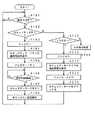
【図13】ドアロック制御モードの一つの例であるオートロックモードでのドアロック制御動作を説明するためのフローチャートの一部である。
【図14】ドアロック制御モードの一つの例であるオートロックモードでのドアロック制御動作を説明するためのフローチャートの一部である。
【図15】ドアロック制御モードの一つの例であるオートロックモードでのドアロック制御動作を説明するためのフローチャートの一部である。
【図16】ドアロック制御モードの一つの例であるオートロックモードでのドアロック制御動作を説明するためのフローチャートの一部である。
【図17】ドアロック制御モードの一つの例であるオートロックモードでのドアロック制御動作を説明するためのフローチャートの一部である。
【図18】ドアロック制御モードの一つの例であるオートロックモードでのドアロック制御動作を説明するためのフローチャートの一部である。
【図19】ドアロック制御モードの一つの例である逐次ロックモードでのドアロック制御動作を説明するためのフローチャートの一部である。
【図20】ドアロック制御モードの一つの例である逐次ロックモードでのドアロック制御動作を説明するためのフローチャートの一部である。
【図21】ドアロック制御モードの一つの例である逐次ロックモードでのドアロック制御動作を説明するためのフローチャートの一部である。
【図22】監視制御装置における通知連絡先の設定入力動作を説明するためのフローチャートの一部である。
【図23】監視制御装置における通知連絡先の設定入力動作を説明するためのフローチャートの一部である。
【図24】監視制御装置のリモートコマンダからの信号の受信処理動作を説明するためのフローチャートである。
【図25】監視制御装置におけるセキュリティモードオン時の動作を説明するためのフローチャートの一部である。
【図26】監視制御装置におけるセキュリティモードオン時の動作を説明するためのフローチャートの一部である。
【図27】監視制御装置におけるセキュリティモードオン時の動作を説明するためのフローチャートの一部である。
【図28】監視制御装置におけるドアロック装置との連携動作を説明するための図である。
【符号の説明】
1…玄関ドア、2…ドアロック装置、3…監視制御装置、4…火災センサ、5…ガスセンサ、6a,6b…窓センサ、7…テレビ受像機、8…電話回線、10…管理サーバ、100…ドアロック制御装置、21in…内側電子鍵リード/ライト部、21ex…外側電子鍵リード/ライト部、40…電子鍵カード[0001]
TECHNICAL FIELD OF THE INVENTION
The present invention relates to a door lock system and a door lock management method that control locking and unlocking of a door using an electronic key.
[0002]
[Prior art]
In a conventional door lock system in which a physical key is inserted into a key cylinder for locking and unlocking, if the key is lost, the key cylinder of the door lock mechanism is not replaced with a key using a key other than the key. As long as there is a risk of being unlocked.
[0003]
In this regard, if a door lock system using an electronic key is used, for example, by changing the number registered as an electronic key, the same operation and effect as when a key cylinder is replaced can be obtained. Can be improved.
[0004]
According to the door lock system using the electronic key, an automatic lock mechanism can be easily adopted, so that the door lock system of a front door or a hotel is very excellent in terms of security as a lock mechanism. .
[0005]
[Problems to be solved by the invention]
However, in a conventional door lock system that unlocks and locks a door with a key, it is not possible to identify a locked person or an unlocked person, and thus it is not possible to grasp the situation of a resident at home.
[0006]
For this reason, it is difficult to cooperate with the indoor security function.Conventionally, when the security mode is to be turned on, after turning on the security mode in the room, all the doors are opened from the entrance door within a predetermined time. The people are leaving the house. This is because the conventional security mode starts after the predetermined time elapses after the security mode is set and started, and if the user does not go out of the house within the predetermined time, the occupant may malfunction as a trespasser. Because it will be.
[0007]
Therefore, after the security mode is started and set, the user must rush out of the house, which is very inconvenient. In addition, there is a demand that the security mode be different between a case where only a child or an elderly person is at home and a case where a father or mother is also at home, but it has been extremely difficult to respond to this request in the past. Met.
[0008]
An object of the present invention is to provide a door lock system that can solve the above problems.
[0009]
[Means for Solving the Problems]
In order to solve the above problems, a door lock system according to the invention of
A door lock mechanism for locking and unlocking the door,
Communication means provided on the door for communicating with an electronic key in which personal identification information is stored;
Storage means for storing at least one personal identification information;
Door lock control for comparing the personal identification information received from the electronic key through the communication unit with the personal identification information stored in the storage means, and controlling locking or unlocking of the door based on the comparison result Means,
Based on the locking or unlocking control of the door based on the comparison result of the personal identification information in the door lock control means, the entry / exit of the individual corresponding to the personal identification information stored in the storage means from the door. Management control means for managing;
It is characterized by having.
[0010]
According to the first aspect of the present invention, the management control means can manage entry / exit from the door at the individual level based on the personal identification information.
[0011]
In the door lock system according to the third aspect of the present invention,
The door lock system according to
Monitoring means for monitoring the interior of the door,
The management control unit controls the monitoring unit according to a home situation based on the entry / exit of the individual.
It is characterized by the following.
[0012]
According to the third aspect of the present invention, it is possible to control the monitoring state by the monitoring means according to the at-home situation based on individual entry / exit.
[0013]
According to a fourth aspect of the present invention, in the door lock system according to the first aspect,
Monitoring means for monitoring the interior of the door at one security level selected from a plurality of security levels prepared in advance,
The management control means selects and sets a security level in the monitoring means according to the home situation.
It is characterized by the following.
[0014]
According to the fourth aspect of the present invention, a plurality of security levels are prepared in advance in accordance with the at-home situation, and an appropriate security level is selected from the plurality of security levels in accordance with the at-home situation based on individual entry / exit. Security level can be selectively controlled.
[0015]
The door lock system according to the invention of
A door lock mechanism for locking and unlocking the door,
Communication means provided on the door for communicating with an electronic key in which personal identification information is stored;
Storage means for storing at least one personal identification information;
Door lock control for comparing the personal identification information received from the electronic key through the communication unit with the personal identification information stored in the storage means, and controlling locking or unlocking of the door based on the comparison result Means,
Monitoring means for monitoring the interior of the door,
Monitoring start requesting means for generating a request to start monitoring by the monitoring means based on communication between the communication means and the electronic key;
It is characterized by having.
[0016]
According to the invention of
[0017]
According to an eighth aspect of the present invention, in the door lock system according to the seventh aspect,
The monitoring start request generating unit is configured to perform monitoring by the monitoring unit based on communication between the communication unit and the electronic key within a predetermined time after the door is locked by the door lock control unit. Generate a request to start
It is characterized by the following.
[0018]
According to this invention, the communication means and the electronic key are made to communicate with each other, for example, after the entrance door is locked, and then the communication means and the electronic key are once again communicated to activate the monitoring means. Can be convenient.
[0019]
According to a tenth aspect of the present invention, in the door lock system according to the seventh aspect,
The monitoring means monitors the interior of the door at one security level selected from a plurality of security levels prepared in advance,
Based on the locking or unlocking control of the door based on the comparison result of the personal identification information in the door lock control means, the entry / exit of the individual corresponding to the personal identification information stored in the storage means from the door. A home status grasping means for managing and monitoring the home status;
A security level setting unit that controls a security level in the monitoring unit according to a home situation grasped by the home situation grasping unit when the monitoring start request is issued from the monitoring start request unit;
It is characterized by having.
[0020]
According to the tenth aspect of the present invention, the at-home status grasping means manages the entry / exit of the individual corresponding to the personal identification information stored in the storage means from the door, and reliably grasps the at-home situation at that time. Therefore, the monitoring means can perform security monitoring at a security level based on the home situation.
[0021]
According to a thirteenth aspect, in the door lock system according to the seventh aspect,
An abnormality notification unit configured to notify the abnormality detection to a preset contact through a communication network when an abnormality is detected by the monitoring unit;
It is characterized by the following.
[0022]
According to the thirteenth aspect of the present invention, for example, by setting the contact information to a mobile phone carried by a user who is out, when the monitoring means detects an abnormality, the abnormality detection notification is made. The user who is out can receive the information, and the user can take appropriate measures such as contacting the police or the like.
[0023]
According to a fourteenth aspect of the present invention, in the door lock system according to the thirteenth aspect,
When contacting the contact by the abnormal contact notifying means, both the contact by voice through the telephone network and the contact by e-mail are executed.
It is characterized by the following.
[0024]
According to the fourteenth aspect of the present invention, for example, when a mobile phone is set as a telephone contact, the mobile phone of the contact happens to be in a place where radio waves cannot be received or the power of the mobile phone is turned off. However, even if a telephone call is not made, the e-mail will be sent at the same time, so if you move to a place where you can receive radio waves with your mobile phone, or if your mobile phone is turned on, There is a merit that communication by e-mail is performed.
[0025]
According to a fifteenth aspect, in the door lock system according to the fourteenth aspect,
The surveillance unit includes a surveillance camera, and the electronic mail attaches image information captured by the surveillance camera.
It is characterized by the following.
[0026]
According to the fifteenth aspect of the present invention, since the image information taken by the surveillance camera is attached to the e-mail, it is possible to grasp the situation that caused the contact from the image information. Therefore, it is possible to grasp whether the report is a false report or an urgent contact.
[0027]
BEST MODE FOR CARRYING OUT THE INVENTION
Hereinafter, an embodiment of a door lock system according to the present invention will be described with reference to the drawings. The example described below is a case where the door lock system of the embodiment is applied to a front door of a house.
[0028]
In this example, a security monitoring system is installed inside the house that detects the intrusion of thieves from windows and entrance doors, the occurrence of fires, and gas leaks, and takes measures to respond to each abnormal situation. The security monitoring system and the door lock system of the embodiment are operated in conjunction with each other.
[0029]
Various types of electronic key devices can be used. In this example, a card (hereinafter, referred to as an electronic key card) in which a control IC (Integrated Circuit) is embedded is used as the electronic key device. Used. A door lock device for locking and unlocking the door with an electronic key card is attached to the entrance door. In this example, communication of key information is performed between the electronic key card and the door lock device, and the door lock device controls locking and unlocking of the door based on the communication.
[0030]
In this example, the communication between the electronic key card and the door lock device is a non-contact communication using, for example, electromagnetic induction or radio waves, and forms a part of the door lock device as described later. Communication is performed via a read / write unit of the electronic key card. In this example, as described later, communication between the electronic key card and the door lock device is performed by electromagnetic induction.
[0031]
As key information for controlling the locking and unlocking of the door, each person has an electronic key card storing the common key information as one common to all residents living in the house. You can also. In this case, the common key information is registered in the door lock device or the device that performs the authentication using the key information, and the door lock device receives the common key information from the electronic key card through communication. Authentication is performed by the own device, or the received common key information is transferred to the authentication device, and the locking or unlocking of the door is controlled in response to the authentication result from the authentication device. Can be.
[0032]
In this example, instead of using such common key information as the key information, in order to be able to manage the entrance and exit of each resident who lives in the house from the front door, the key is used. As the information, a personal identifier (hereinafter, referred to as a personal ID) uniquely corresponding to each resident living in the house is used.
[0033]
For this reason, in the door lock system of this example, all the residents who live in the house each have an electronic key card composed of an IC card in which a personal ID for identifying oneself is written. On the other hand, in the door lock device or the device for performing authentication, the personal IDs of all the residents living in the house are registered in advance. Then, the door lock device receives each personal ID from the electronic key card by communication and performs authentication by itself, or transfers the received personal ID to the device that performs authentication, and transmits the received personal ID to the device that performs authentication. In response to the authentication result, the locking or unlocking of the door is controlled.
[0034]
As described above, by using the personal ID to reflect the management information of entry / exit from the entrance door of each resident who lives in the house in the security system, a more sophisticated security system can be constructed.
[0035]
[Overview of Security System Including Door Lock System of Embodiment]
FIG. 1 is a diagram illustrating an outline of a security system including a door lock system according to an embodiment.
[0036]
A
[0037]
The
[0038]
In this example, in the room, a
[0039]
Although not shown in FIG. 1, when a fire occurrence is detected by the
[0040]
The
[0041]
The
[0042]
Next, a specific configuration example of the
[0043]
[Configuration of door lock device]
FIGS. 2A and 2B are diagrams for explaining a configuration example of the
[0044]
In the
[0045]
Also, inside the entrance door 1 (indoor side), an inside electronic key reader / writer unit 21in for communicating with the electronic key card and the result of authentication of the electronic key card and the locking or unlocking of the
[0046]
The
[0047]
The entrance
[0048]
The
[0049]
Although not shown, a concave portion is formed on the end face of the wall facing the end face 1a of the
[0050]
As the entrance door opening /
[0051]
[Description of Door Lock Control Device 100]
Next, FIG. 3 shows an electrical configuration example of the
[0052]
That is, the door
[0053]
In the
[0054]
The
[0055]
Further, a door opening /
[0056]
The electronic key read / write unit 21ex or 21in forms a communication unit that communicates with the electronic
[0057]
The door
[0058]
In the auto lock mode, the
[0059]
In the sequential lock mode, the state of locking and unlocking the entrance door is changed based on communication with the electronic key card through at least the electronic key read / write unit 21ex on the outside of the
[0060]
In this example, the selection of whether the door lock control mode of the
[0061]
Information on which door lock control mode the
[0062]
Note that the selection of whether the door lock control mode of the
[0063]
[Configuration Example of Electronic Key Device]
As the electronic key device, a mobile phone terminal, a PDA (Personal Digital Assistant), or the like can be used in addition to the electronic
[0064]
FIG. 4 is a diagram showing a configuration example when the electronic key device is an electronic
[0065]
The control IC 42 includes a memory and stores identification information serving as electronic key information, a name of the owner, a personal ID, and other necessary personal information of the owner. The personal information is configured so that a father, a mother, a child, and the like can be distinguished. In addition, the time and history of communication with the electronic key read / write unit 21ex or 21in performed by each owner (information as to which of the inner and outer electronic key read / write units was communicated is stored in the memory in the control IC 42). ) And the history of each owner going out and returning home.
[0066]
These pieces of history information are also stored in an area corresponding to each person in a
[0067]
FIG. 5 shows an internal block configuration of the electronic
[0068]
An information transmission / reception circuit 408 connected to the
[0069]
Further, information received by the
[0070]
[Description of Appearance of Monitoring and Control Device 3]
FIG. 6 is an external view for explaining the configuration of the
[0071]
A
[0072]
The shooting direction of the
[0073]
The
[0074]
The
[0075]
The
[0076]
The
[0077]
Although not shown in FIG. 6, a video output terminal connected to a video input terminal of the
[0078]
Further, the
[0079]
[Configuration example of monitoring control device 3]
FIG. 7 shows an example of the internal configuration of the
[0080]
The
[0081]
The
[0082]
Further, the
[0083]
The
[0084]
The entry / exit history information of this example stores the time of going out and the time of returning home, and also includes a presence / absence flag indicating whether the user is going out or at home. The entry / exit history information is used by the
[0085]
Further, in this example, the
[0086]
As shown in FIG. 9, in this example, the security levels are, in order from the highest security level, level A, level B, level C, and level D. In level A, monitoring of windows and entrance doors is performed. At the level B, the monitoring of the windows and the entrance doors and the monitoring of the fires and gas leaks are performed without monitoring by the
[0087]
Then, as shown in FIG. 8, each security level is assigned to each of the family members' home status. That is, in this example, when the father is at home, the level is set to the level D at which monitoring is not performed. In the situation where the father is absent but the mother is at home, the level is set to level C in which only monitoring of fire and gas leakage is performed. When only children are at home, the level is set to level B for monitoring windows and entrance doors and monitoring for fires and gas leaks. Then, in a situation where all members are absent, the level is set to level A where all monitoring is performed.
[0088]
When turning on the security mode or changing the security level, the
[0089]
The relationship between the security level in FIG. 8 and the home status of family members can be set in advance, or by the user inputting and setting to the
[0090]
It is needless to say that the table information in FIGS. 8 and 9 may be stored in another memory instead of the
[0091]
The door lock
[0092]
The image /
[0093]
In this example, the monitoring information area stores image information and audio information for a predetermined time, for example, 30 seconds, in a so-called ring buffer format. It should be noted that the monitoring information area and the message information area may have different memory configurations.
[0094]
The
[0095]
The
[0096]
The notification
[0097]
[Description of Remote Commander 50]
As shown in FIG. 7, the remote commander 50 for the
[0098]
In this example, registration of a personal ID as electronic key information in the
[0099]
Next, various operations of the door lock system configured as described above will be described below.
[0100]
[Registration of Electronic Key Information of Electronic Key Card 40]
Since it is not preferable from the viewpoint of security that the registration of the personal ID as the electronic key information can be easily performed, in this example, the registration of the personal ID as the electronic key information is performed by a method that emphasizes security as follows. For example, it is performed by a dealer or an installer or a user of the
[0101]
First, a personal computer having an electronic key read / write unit is prepared. The personal computer accesses the homepage of the
[0102]
When the registration button is clicked while accessing the registration page of the electronic key information, the personal computer reads the personal information including the personal ID from the electronic
[0103]
Then, the
[0104]
The
[0105]
Note that the above-described operation of registering the personal ID as the electronic key information is merely an example. For example, the
[0106]
[Message recording and message reproduction in
As described above, the
[0107]
Then, when a message is recorded in the
[0108]
FIG. 10 is a flowchart for explaining the processing of the
[0109]
That is, first, in order to record or reproduce a message, the user holds his / her electronic
[0110]
Next, it waits for the arrival of a remote control signal from the remote commander 50 (step S3). After confirming that the remote control signal has been received, it is determined whether or not the remote control signal is caused by the operation of the message recording button 53 (step S4). If it is determined that the operation is performed by operating the message recording button 53, the
[0111]
In this message recording operation, the
[0112]
Next, the
[0113]
The operator uses the
[0114]
If it is determined in step S4 that the remote control signal is not due to the operation of the message recording button 53, it is determined whether or not the signal is due to the operation of the message playback button 54 (step S5). When it is determined that the operation is not performed by operating the
[0115]
If it is determined in step S5 that the message is due to the operation of the
[0116]
When it is determined in step S7 that there is no message addressed to the operator, the
[0117]
When it is determined in step S7 that there is a message addressed to the operator, the message image and the message voice addressed to the operator are read out from the image /
[0118]
When the reproduction of the message is completed, the
[0119]
If it is determined in step S10 that the message is not to be deleted, the message recording / reproducing process routine is terminated.
[0120]
[Selection setting of door lock control mode; FIGS. 11 and 12]
As described above, in this embodiment, the setting of the door lock control mode can be performed through the
[0121]
First, the
[0122]
If it is determined in step S21 that the specific button operation is not performed, other processing such as processing corresponding to a single button operation is performed (step S22). When it is determined in step S21 that the specific button operation has been performed, a list of setting menus is displayed on the screen of the
[0123]
With respect to the list display of the setting menu, the operator uses the cursor keys of the remote commander 50 to select a desired setting menu item. The
[0124]
When it is determined in step S26 that the setting item determination operation is not performed, the process returns to step S24. If it is determined in step S26 that the setting item determination operation has been performed, it is determined whether or not the selected setting item is the setting of the door lock control mode (step S27). If not, the selected item is selected. A processing routine for other setting items is executed (step S28).
[0125]
When it is determined in step S27 that the selected setting item is the setting of the door lock control mode, the
[0126]
Therefore, the
[0127]
That is, the
[0128]
If it is determined in step S30 that the automatic lock mode is not set, the
[0129]
That is, the
[0130]
The operation at the time of setting the lock control mode in the
[0131]
Next, the operation of the door
[0132]
First, the
[0133]
If it is determined in step S41 that the door lock control mode setting instruction information has been received from the
[0134]
When it is determined in step S43 that the selected and instructed door lock control mode is the automatic lock mode, the
[0135]
That is, in step S44, the
[0136]
When it is determined in step S43 that the selected and instructed door lock control mode is the sequential lock mode, the
[0137]
That is, in step S45, the
[0138]
In this example, both the inner electronic key read / write unit 21in and the outer electronic key read / write unit 21ex are used in the sequential lock mode, but in this sequential lock mode, the outer electronic key is used. It is also possible to activate only the read / write unit ex and not use the inner electronic key read / write unit 21in. In that case, locking from the inside of the house is a problem. For example, a configuration may be adopted in which the entrance door can be locked manually from the inside without using an electronic key card.
[0139]
Next, the operation of the
[0140]
[Auto lock mode; FIGS. 13 to 18]
The operation in the auto lock mode will be described with reference to the flowcharts of FIGS. In the automatic lock mode, the
[0141]
The
[0142]
Then, in step S51, when it is determined that the electronic
[0143]
Next, the
[0144]
[In the case of communication in the inner electronic key read / write unit 21in; FIGS. 13 to 15]
If it is determined in step S53 that the communication with the electronic
[0145]
The
[0146]
Then, the authentication result is discriminated (step S55), and none of the personal IDs stored in the
[0147]
If it is determined in step S55 that some of the personal IDs stored in the
[0148]
Then, at this time, since the authentication is OK, the
[0149]
At this time, the
[0150]
On the other hand, the
[0151]
The door
[0152]
Then, when determining that the window is open, the
[0153]
Next, the
[0154]
If it is determined in step S66 that the
[0155]
Thereafter, the
[0156]
Thereafter, the
[0157]
Then, in step S83, when it is determined that the predetermined time has elapsed without communication between the electronic key card and the outer electronic key read / write unit 21ex, the
[0158]
Also, in step S84, after the entrance door has been locked and before the lapse of a predetermined period of time in which the outer LED 22ex stops blinking green, the electronic key card and the outer electronic key read / write unit 21ex determined to have communicated in step S51. When it is determined that the communication has been performed, the door lock confirmed in steps S61 to S63 is reconfirmed (step S85).
[0159]
If it is determined in step S85 that the closing is OK, the
[0160]
In response to this request, the
[0161]
The
[0162]
Also, in step S87, when it is determined that a response to the effect that the security mode cannot be turned on has been received from the
[0163]
When it is determined in step S85 that the window is open and the doors are not closed, the
[0164]
[In the case of communication by the outer electronic key read / write unit 21ex; FIGS. 16 to 18]
In step S51, when it is determined that the communication with the electronic
[0165]
First, the
[0166]
Then, the authentication result is discriminated (step S102), and there is no personal ID stored in the
[0167]
If it is determined in step S102 that some of the personal IDs stored in the
[0168]
Then, at this time, since the authentication is OK, the
[0169]
Next, the
[0170]
Thereafter, the
[0171]
Then, in step S111, when it is determined that the predetermined time has elapsed without performing communication between the electronic
[0172]
Further, in step S112, before the predetermined time elapses after the entrance door is locked, communication is performed between the electronic
[0173]
The confirmation of the door closing in step S113 is performed in the same manner as the processing described in steps S61 to S63. That is, the door
[0174]
If it is determined in step S113 that the closing is OK, the
[0175]
In response to this request, the
[0176]
The
[0177]
When it is determined in step S115 that a response to the effect that the security mode cannot be turned on has been received from the
[0178]
If it is determined in step S113 that the window is open and the doors are not closed, the
[0179]
In steps S111 to S118, the security mode is turned on by holding the electronic
[0180]
That is, once the
[0181]
Next, in step S107, when it is determined that the
[0182]
Thereafter, the
[0183]
After that, the
[0184]
The
[0185]
The
[0186]
If it is determined in step S128 that the security mode has been changed, the
[0187]
In the above description, when there is a returnee, the door
[0188]
[Explanation of the sequential lock mode; FIGS. 19 to 21]
Next, the operation in the sequential lock mode will be described with reference to the flowcharts of FIGS. In the sequential lock mode, the electronic
[0189]
The
[0190]
Then, in step S131, when it is determined that the electronic
[0191]
It is determined which of the inside electronic key read / write unit 21in and the outside electronic key read / write unit 21ex has communicated with the electronic key card 40 (step S133).
[0192]
[In the case of communication in the inner electronic key read / write unit 21in; FIG. 19]
If it is determined in step S133 that the communication with the electronic
[0193]
The
[0194]
Then, the authentication result is determined (step S135), and none of the personal IDs stored in the
[0195]
If it is determined in step S135 that some of the personal IDs stored in the
[0196]
Then, the
[0197]
Then, the
[0198]
Then, the
[0199]
If it is determined in step S138 that the current lock state of the
[0200]
Then, at this time, the
[0201]
[In the case of communication by the outer electronic key read / write unit 21ex; FIGS. 20 to 21]
In step S131, when it is determined that the communication with the electronic
[0202]
The
[0203]
Then, the authentication result is discriminated (step S152), and none of the personal IDs stored in the
[0204]
If it is determined in step S102 that some of the personal IDs stored in the
[0205]
Then, the
[0206]
Then, the
[0207]
Further, when it is determined in step S155 that the current locked state of the
[0208]
Then, the
[0209]
Then, the
[0210]
After locking, the
[0211]
If it is determined in step S163 that the communication has been performed between the electronic key card determined to have been performed in step S51 and the outer electronic key read / write unit 21ex before the predetermined time has elapsed after the entrance door is locked, Then, the door lock is confirmed (step S164).
[0212]
The confirmation of the door closing in step S164 is performed in the same manner as the processing described in steps S61 to S63. That is, the door
[0213]
If it is determined in step S164 that the closing is OK, the
[0214]
In response to this request, the
[0215]
The
[0216]
When it is determined in step S166 that a response indicating that the security mode cannot be turned on has been received from the
[0217]
If it is determined in step S164 that the window is open and the doors are not closed, the
[0218]
[Operation of the
[Operation for setting notification contact when an abnormality occurs; FIGS. 22 and 23]
In this embodiment, when an abnormality is detected, the
[0219]
FIG. 22 and FIG. 23 are flowcharts of processing for inputting various settings to the
[0220]
First, the
[0221]
If it is determined in step S171 that a button operation has been performed on the remote commander 50, the
[0222]
When it is determined in step S173 that the operated button is the
[0223]
For this menu list display, the operator selects a setting menu item to be performed using the cursor keys of the remote commander 50. The
[0224]
If it is determined in step S177 that a menu item selection operation has not been performed, the
[0225]
If it is determined in step S179 that a setting item determination operation has been performed, the
[0226]
In step S181, when it is determined that the selected item is the setting of the notification contact, the setting screen of the notification contact is displayed on the screen of the
[0227]
Then, it is determined whether or not the input of the setting items of the notification contact has been completed (step S186). When it is determined that the input has been completed, the information of the input notification contact is stored in the notification communication setting memory 222 (step S187). Then, the power of the
[0228]
[Security operation in
As described above, the
[0229]
FIG. 24 is a flowchart for explaining an operation of controlling the security mode of the monitoring and
[0230]
First, the
[0231]
As a result of the determination in step S192, when it is determined that the operation is the operation of the
[0232]
Then, the
[0233]
Then, after a lapse of the predetermined time, for example, 5 minutes, the
[0234]
If it is determined in step S192 that the button operated by the remote commander 50 is not the
[0235]
As a result of the determination in step S199, when it is determined that the button is the
[0236]
Then, the
[0237]
Then, the
[0238]
[Monitoring operation when security mode is on]
FIG. 25, FIG. 26, and FIG. 27 show processing operations when the security mode is turned on in the
[0239]
In FIG. 23, first, the
[0240]
Next, the
[0241]
Next, the
[0242]
If it is determined in step S221 that no abnormality has been detected, the
[0243]
If it is determined in step S214 that an intruder has been detected by the
[0244]
Next, the
[0245]
Next, the
[0246]
Next, the
[0247]
Then, the
[0248]
Then, when determining that the
[0249]
When it is determined in step S221 that an abnormality has been detected, the
[0250]
Then, the
[0251]
Next, the
[0252]
Next, the
[0253]
Then, the
[0254]
When it is determined in step S222 that an abnormality has been detected by the
[0255]
Next, the
[0256]
As described above, in this embodiment, when the e-mail address is set as the contact, the abnormality detection notification is sent by e-mail in addition to the telephone communication. Therefore, even if the mobile phone terminal is out of radio waves or the power is turned off, and the abnormality detection notification by telephone communication does not arrive, the notification contact will be securely notified by the abnormality detection notification by e-mail. Will arrive at
[0257]
In this embodiment, since the image information captured by the surveillance camera is attached to the e-mail, the user who has received the notification can see the outline of the abnormal state by looking at the image information. This makes it possible to detect false alarms and take appropriate measures for emergency situations.
[0258]
Further, in this embodiment, the
[0259]
[Cooperation by an instruction from the door
The
[0260]
That is, the
[0261]
When it is determined in step S251 that the instruction to turn on the security mode has been received, the
[0262]
If it is determined in step S254 that the security mode cannot be turned on, the
[0263]
On the other hand, when it is determined in step S254 that the security mode can be turned on, the fact that the security mode can be turned on is notified to the door lock control device 100 (step S256). (Step S257).
[0264]
After confirming that the predetermined time has elapsed, the
[0265]
During this security monitoring operation, it is determined whether or not personal information including a personal ID has been received from the door lock control device 100 (step S260), and if not received, the process returns to step S259 to continue the security monitoring operation. When it is determined that the personal information has been received from the door
[0266]
When determining that the security level does not need to be changed, the
[0267]
If it is determined in step S263 that the security mode should be turned off, the security mode is turned off (step S266), and the fact is notified to the door lock control device 100 (step S267). Then, the process returns to step S251.
[0268]
As described above, according to this embodiment, since locking and unlocking are performed using a non-contact electronic key card, there is no keyhole, and there is a so-called anti-picking security effect.
[0269]
In addition, since the
[0270]
Further, the inside electronic key read / write unit 21in is provided, and the locked state of the door can be controlled by the inside electronic key read / write unit 21in using the electronic key card. It can prevent you from exiting the entrance door.
[0271]
In addition, by providing the inside electronic key read / write unit 21in and the outside electronic key read / write unit 21ex, it is easy to manage entry / exit of a family through communication between them and the electronic key card.
[0272]
Therefore, by combining the
[0273]
In addition, when the user forgets to close the window, it is confirmed when the door is opened and closed, so that the user can prevent forgetting to close the window.
[0274]
Further, since the security mode level can be changed according to the age, gender, etc. of the family members, an effective security level can be set even when the resident is a weak person. Another advantage is that the security level can be changed by grasping a change in the home situation in cooperation with the unlocking and locking of the door lock.
[0275]
[Other Embodiments, Modifications]
In the above-described embodiment, the security mode is turned on when the electronic
[0276]
In this case, when the door
[0277]
Note that, in this example, when the resident unlocks the
[0278]
In the above description of the embodiment, the authentication of the personal ID as the key information is performed by the door lock device. However, the
[0279]
Also, the personal IDs of the unlocker and the locker may be sent to the
[0280]
Further, in the above description, whether the person is an out-of-home person or a returning person is determined by the door
[0281]
Note that the electronic key is not limited to an IC card. For example, a mobile phone or a portable information device having a control IC and communication means similar to the IC card can be used as the electronic key.
[0282]
Further, the electronic key is not limited to one that performs communication of electronic key information in a non-contact manner as in the above-described embodiment, and may be one that performs communication of electronic key information in a contact manner. .
[0283]
【The invention's effect】
As described above, according to the present invention, entry and exit from a door can be managed at an individual level, and security management can be performed according to the home situation.
[Brief description of the drawings]
FIG. 1 is a diagram for describing an outline of a security system including an embodiment of a door lock system.
FIG. 2 is a diagram illustrating a main part of the embodiment of the door lock system.
FIG. 3 is a diagram illustrating a configuration example of a door lock device according to an embodiment.
FIG. 4 is a diagram illustrating an example of an electronic key device.
FIG. 5 is a block diagram illustrating an internal configuration of an example of an electronic key device.
FIG. 6 is a diagram illustrating an example of a monitoring control device used in a security system.
FIG. 7 is a block diagram illustrating a configuration example of the monitoring control device of FIG. 6;
FIG. 8 is a diagram for explaining the contents of a security mode.
FIG. 9 is a diagram for explaining the contents of a security mode.
FIG. 10 is a flowchart for explaining a message recording and reproducing function of the monitoring control device of FIG. 6;
FIG. 11 is a flowchart illustrating a setting operation of a door lock control mode.
FIG. 12 is a flowchart illustrating a setting operation of a door lock control mode.
FIG. 13 is a part of a flowchart for describing a door lock control operation in an auto lock mode which is one example of the door lock control mode.
FIG. 14 is a part of a flowchart for describing a door lock control operation in an auto lock mode which is one example of the door lock control mode.
FIG. 15 is a part of a flowchart for describing a door lock control operation in an auto lock mode, which is one example of the door lock control mode.
FIG. 16 is a part of a flowchart for describing a door lock control operation in an auto lock mode, which is one example of the door lock control mode.
FIG. 17 is a part of a flowchart for describing a door lock control operation in an auto lock mode, which is one example of the door lock control mode.
FIG. 18 is a part of a flowchart for describing a door lock control operation in an auto lock mode, which is one example of the door lock control mode.
FIG. 19 is a part of a flowchart for explaining a door lock control operation in a sequential lock mode, which is one example of the door lock control mode.
FIG. 20 is a part of a flowchart for describing a door lock control operation in a sequential lock mode, which is one example of the door lock control mode.
FIG. 21 is a part of a flowchart for describing a door lock control operation in a sequential lock mode, which is one example of the door lock control mode.
FIG. 22 is a part of a flowchart for describing a notification contact setting input operation in the monitoring control device.
FIG. 23 is a part of a flowchart for describing a notification contact setting input operation in the monitoring control device.
FIG. 24 is a flowchart for explaining an operation of the monitoring control device for receiving a signal from a remote commander.
FIG. 25 is a part of a flowchart for describing an operation when the security mode is turned on in the monitoring control apparatus.
FIG. 26 is a part of a flowchart for describing an operation when the security mode is turned on in the monitoring control device.
FIG. 27 is a part of a flowchart for describing an operation when the security mode is turned on in the monitoring control device.
FIG. 28 is a diagram for explaining a cooperative operation of the monitoring control device with a door lock device.
[Explanation of symbols]
DESCRIPTION OF
Claims (23)
Translated fromJapanese前記ドアに設けられ、個人識別情報が記憶されている電子鍵と通信を行なうための通信手段と、
少なくとも1つの個人識別情報を記憶する記憶手段と、
前記通信部を通じて電子鍵から受信する前記個人識別情報と、前記記憶手段に記憶されている前記個人識別情報とを比較し、その比較結果に基づいてドアの施錠または開錠を制御するドアロック制御手段と、
前記ドアロック制御手段での前記個人識別情報の比較結果に基づいたドアの施錠または開錠制御に基づいて、前記記憶手段に記憶する前記個人識別情報に対応する個人の前記ドアからの入退出を管理する管理制御手段と、
を備えることを特徴とするドアロックシステム。A door lock mechanism for locking and unlocking the door,
Communication means provided on the door for communicating with an electronic key in which personal identification information is stored;
Storage means for storing at least one personal identification information;
Door lock control for comparing the personal identification information received from the electronic key through the communication unit with the personal identification information stored in the storage means, and controlling locking or unlocking of the door based on the comparison result Means,
Based on the locking or unlocking control of the door based on the comparison result of the personal identification information in the door lock control means, the entry / exit of the individual corresponding to the personal identification information stored in the storage means from the door. Management control means for managing;
A door lock system comprising:
前記ドアの室内の戸締りを監視する戸締り監視手段と、
前記戸締り監視手段により室内の戸締りが完全でないときには、前記ドアロック制御手段による前記ドアの施錠の前に、戸締りが不完全であることを告知する告知手段と
を備えることを特徴とするドアロックシステム。The door lock system according to claim 1,
Door-locking monitoring means for monitoring door-tightening of the door indoors,
A door lock system comprising, before the door is locked by the door lock control unit, a notifying unit for notifying that the door locking is incomplete, when the indoor locking by the door locking monitoring unit is not complete. .
前記ドアの室内を監視する監視手段を備え、
前記管理制御手段は、前記個人の入退出に基づく在宅状況に応じて前記監視手段を制御する
ことを特徴とするドアロックシステム。The door lock system according to claim 1,
Monitoring means for monitoring the interior of the door,
A door lock system, wherein the management control means controls the monitoring means in accordance with a home situation based on the entry / exit of the individual.
予め用意された複数通りのセキュリティレベルの中から選択された一つのセキュリティレベルで前記ドアの室内を監視する監視手段を備え、
前記管理制御手段は、前記在宅状況に応じて前記監視手段におけるセキュリティレベルを選択設定する
ことを特徴とするドアロックシステム。The door lock system according to claim 1,
Monitoring means for monitoring the interior of the door at one security level selected from a plurality of security levels prepared in advance,
The door lock system, wherein the management control means selects and sets a security level in the monitoring means according to the home situation.
予め用意された複数通りのセキュリティレベルの中から選択された一つのセキュリティレベルで前記ドアの室内を監視する監視手段を備え、
前記管理制御手段は、前記個人の入退出に基づく前記在宅状況の変化により、前記監視手段におけるセキュリティレベルの変更制御をする
ことを特徴とするドアロックシステム。The door lock system according to claim 1,
Monitoring means for monitoring the interior of the door at one security level selected from a plurality of security levels prepared in advance,
A door lock system, wherein the management control means controls change of a security level in the monitoring means based on a change in the home situation based on the entry / exit of the individual.
前記監視手段におけるセキュリティレベルが変更されたときに、当該変更を告知する手段を設けた
ことを特徴とするドアロックシステム。The door lock system according to claim 5,
A door lock system, further comprising means for notifying the change when the security level in the monitoring means is changed.
前記ドアに設けられ、個人識別情報が記憶されている電子鍵と通信を行なうための通信手段と、
少なくとも1つの個人識別情報を記憶する記憶手段と、
前記通信部を通じて電子鍵から受信する前記個人識別情報と、前記記憶手段に記憶されている前記個人識別情報とを比較し、その比較結果に基づいてドアの施錠または開錠を制御するドアロック制御手段と、
前記ドアの室内を監視する監視手段と、
前記通信手段と前記電子鍵との通信に基づいて、前記監視手段により監視を開始させる要求を発生する監視開始要求手段と、
を備えるドアロックシステム。A door lock mechanism for locking and unlocking the door,
Communication means provided on the door for communicating with an electronic key in which personal identification information is stored;
Storage means for storing at least one personal identification information;
Door lock control for comparing the personal identification information received from the electronic key through the communication unit with the personal identification information stored in the storage means, and controlling locking or unlocking of the door based on the comparison result Means,
Monitoring means for monitoring the interior of the door,
Monitoring start requesting means for generating a request to start monitoring by the monitoring means based on communication between the communication means and the electronic key;
Door lock system comprising:
前記監視開始要求発生手段は、前記ドアロック制御手段により前記ドアが施錠された後、所定時間以内に前記通信手段と前記電子鍵とで通信が行なわれることに基づいて、前記監視手段により監視を開始させる要求を発生する
ことを特徴とするドアロックシステム。The door lock system according to claim 7,
The monitoring start request generating unit is configured to perform monitoring by the monitoring unit based on communication between the communication unit and the electronic key within a predetermined time after the door is locked by the door lock control unit. A door lock system for generating a request to start.
前記ドアの室内の戸締りを監視する戸締り監視手段と、
前記戸締り監視手段により室内の戸締りが完全でないときには、前記ドアロック制御手段による前記ドアの施錠の前に、戸締りが不完全であることを告知する告知手段と
を備えることを特徴とするドアロックシステム。The door lock system according to claim 7,
Door-locking monitoring means for monitoring door-tightening of the door indoors,
A door lock system comprising, before the door is locked by the door lock control unit, a notifying unit for notifying that the door locking is incomplete, when the indoor locking by the door locking monitoring unit is not complete. .
前記監視手段は、予め用意された複数通りのセキュリティレベルの中から選択された一つのセキュリティレベルで前記ドアの室内を監視するものであり、
前記ドアロック制御手段での前記個人識別情報の比較結果に基づいたドアの施錠または開錠制御に基づいて、前記記憶手段に記憶する前記個人識別情報に対応する個人の前記ドアからの入退出を管理して、在宅状況を把握する在宅状況把握手段と、
前記監視開始要求手段から前記監視の開始要求があったときに、前記在宅状況把握手段で把握されている在宅状況に応じて、前記監視手段でのセキュリティレベルを制御するセキュリティレベル設定手段と、
を備えることを特徴とするドアロックシステム。The door lock system according to claim 7,
The monitoring means monitors the interior of the door at one security level selected from a plurality of security levels prepared in advance,
Based on the locking or unlocking control of the door based on the comparison result of the personal identification information in the door lock control means, the entry / exit of the individual corresponding to the personal identification information stored in the storage means from the door. A home status grasping means for managing and monitoring the home status;
A security level setting unit that controls a security level in the monitoring unit according to a home situation grasped by the home situation grasping unit when the monitoring start request is issued from the monitoring start request unit;
A door lock system comprising:
前記ドアからの入退出により在宅状況が変化したときに、前記在宅状況把握手段で把握される在宅状況の変化に応じて、前記監視手段でのセキュリティレベルを変更制御する手段を備える
ことを特徴とするドアロックシステム。The door lock system according to claim 10,
When the home situation changes due to the entrance / exit from the door, according to a change in the home situation grasped by the home situation grasping means, a means for changing and controlling a security level in the monitoring means is provided. Door lock system.
前記電子鍵と前記通信手段との通信は、非接触である
ことを特徴とするドアロックシステム。The door lock system according to claim 1, wherein
A communication between the electronic key and the communication means is in a non-contact manner, wherein a door lock system is provided.
前記監視手段により異常を検知したときに、当該異常検知を、予め設定されている連絡先に通信ネットワークを通じて連絡するようにする異常連絡通知手段を備える
ことを特徴とするドアロックシステム。The door lock system according to claim 7,
A door lock system, comprising: an abnormality notification unit configured to notify a predetermined contact via a communication network when an abnormality is detected by the monitoring unit.
前記異常連絡通知手段による前記連絡先への連絡の際には、電話網を通じた音声による連絡と、電子メールによる連絡の双方を実行する
ことを特徴とするドアロックシステム。The door lock system according to claim 13,
A door lock system, wherein, when contacting the contact by the abnormal contact notifying means, both contact by voice through a telephone network and contact by electronic mail are executed.
前記監視手段は監視カメラを含み、前記電子メールには、前記監視カメラによる撮影画像情報を添付する
ことを特徴とするドアロックシステム。The door lock system according to claim 14,
The door lock system according to claim 1, wherein the monitoring means includes a monitoring camera, and information of an image captured by the monitoring camera is attached to the e-mail.
前記通信検知工程で検知された通信に基づいて、前記電子鍵から前記個人識別情報を受信する個人識別情報受信工程と、
前記個人識別情報受信工程で受信した前記個人識別情報と、予め記憶部に記憶されている個人識別情報とを比較して、その比較結果に基づいてドアの施錠または開錠を制御するドアロック制御工程と、
前記ドアロック制御工程での前記個人識別情報の比較結果に基づいたドアの施錠または開錠制御に基づいて、前記記憶部に記憶されている前記個人識別情報に対応する個人の前記ドアからの入退出を管理する管理工程と、
を備えることを特徴とするドアロック管理方法。A communication detecting step of detecting that communication has been performed with an electronic key in which personal identification information is stored, by a communication unit provided on the door;
Based on the communication detected in the communication detection step, personal identification information receiving step of receiving the personal identification information from the electronic key,
Door lock control for comparing the personal identification information received in the personal identification information receiving step with personal identification information stored in a storage unit in advance, and controlling locking or unlocking of a door based on the comparison result. Process and
Based on the door locking or unlocking control based on the comparison result of the personal identification information in the door lock control step, the entry of an individual corresponding to the personal identification information stored in the storage unit from the door. A management process for managing exits,
A door lock management method, comprising:
前記管理工程では、前記個人の入退出に基づく在宅状況に応じて、前記ドアの室内を監視する監視手段を制御する
ことを特徴とするドアロック管理方法。The door lock management method according to claim 16,
In the management step, a door lock management method includes controlling a monitoring unit that monitors the interior of the door according to a home situation based on the entry and exit of the individual.
前記管理工程では、前記個人の入退出に基づく在宅状況に応じて、前記ドアの室内を監視する監視手段でのセキュリティレベルを制御する
ことを特徴とするドアロック管理方法。The door lock management method according to claim 16,
In the management step, a security level is controlled by a monitoring unit that monitors the interior of the door according to a home situation based on the entry / exit of the individual.
前記通信検知工程で検知された通信に基づいて、前記電子鍵から前記個人識別情報を受信する個人識別情報受信工程と、
前記個人識別情報受信工程で受信した前記個人識別情報と、予め記憶部に記憶されている個人識別情報とを比較して、その比較結果に基づいてドアの施錠または開錠を制御するドアロック制御工程と、
前記通信検知工程で検知された通信が、予め定められた特定の条件の下における通信であったときに、前記ドアの室内を監視する監視手段により監視を開始させる要求を発生する監視開始要求工程と、
を備えることを特徴とするドアロック管理方法。A communication detecting step of detecting that communication has been performed with an electronic key in which personal identification information is stored, by a communication unit provided on the door;
Based on the communication detected in the communication detection step, personal identification information receiving step of receiving the personal identification information from the electronic key,
Door lock control for comparing the personal identification information received in the personal identification information receiving step with personal identification information stored in a storage unit in advance, and controlling locking or unlocking of a door based on the comparison result. Process and
A monitoring start requesting step of, when the communication detected in the communication detecting step is a communication under a predetermined specific condition, generating a request to start monitoring by monitoring means for monitoring the interior of the door; When,
A door lock management method, comprising:
前記監視開始要求発生工程では、前記ドアが施錠された後、所定時間以内に前記通信手段と電子鍵とで通信が行なわれることに基づいて、前記監視手段により監視を開始させる要求を発生する
ことを特徴とするドアロック管理方法。The door lock management method according to claim 19,
In the monitoring start request generating step, a request to start monitoring by the monitoring unit is generated based on communication between the communication unit and the electronic key within a predetermined time after the door is locked. A door lock management method.
前記監視手段は、予め用意された複数通りのセキュリティレベルの中から選択された一つのセキュリティレベルで前記ドアの室内を監視するものであり、
前記ドアロック制御工程での前記個人識別情報の比較結果に基づいたドアの施錠または開錠制御に基づいて、前記記憶部に記憶されている前記個人識別情報に対応する個人の前記ドアからの入退出を管理して、在宅状況を把握する在宅状況把握する管理工程と、
前記監視開始要求工程で前記監視の開始要求が発生したときに、前記在宅状況把握工程で把握されている在宅状況に応じて、前記監視手段でのセキュリティレベルを制御するセキュリティレベル設定工程と、
を備えることを特徴とするドアロック管理方法。The door lock management method according to claim 19,
The monitoring means monitors the interior of the door at one security level selected from a plurality of security levels prepared in advance,
Based on the door locking or unlocking control based on the comparison result of the personal identification information in the door lock control step, the entry of the individual corresponding to the personal identification information stored in the storage unit from the door. A management process for managing the exit and grasping the home situation,
When the monitoring start request occurs in the monitoring start requesting step, a security level setting step of controlling a security level in the monitoring unit according to the home state grasped in the home state grasping step,
A door lock management method, comprising:
前記ドアからの入退出により在宅状況が変化したときに、前記在宅状況把握工程で把握される在宅状況の変化に応じて、前記監視手段でのセキュリティレベルを変更制御する工程を備える
ことを特徴とするドアロック管理方法。The door lock management method according to claim 21,
When the home status changes due to the entrance / exit from the door, a step of changing and controlling the security level in the monitoring means according to the change in the home status grasped in the home situation grasping step is provided. Door lock management method.
前記電子鍵と前記ドアに設けられる前記通信手段との通信は、非接触である
ことを特徴とするドアロック管理方法。The door lock management method according to any one of claims 16 to 22,
Communication between the electronic key and the communication means provided in the door is non-contact, and a door lock management method is provided.
Priority Applications (1)
| Application Number | Priority Date | Filing Date | Title |
|---|---|---|---|
| JP2002359716AJP4318021B2 (en) | 2002-07-31 | 2002-12-11 | Door lock system and door lock management method |
Applications Claiming Priority (2)
| Application Number | Priority Date | Filing Date | Title |
|---|---|---|---|
| JP2002223936 | 2002-07-31 | ||
| JP2002359716AJP4318021B2 (en) | 2002-07-31 | 2002-12-11 | Door lock system and door lock management method |
Publications (3)
| Publication Number | Publication Date |
|---|---|
| JP2004124686Atrue JP2004124686A (en) | 2004-04-22 |
| JP2004124686A5 JP2004124686A5 (en) | 2005-10-27 |
| JP4318021B2 JP4318021B2 (en) | 2009-08-19 |
Family
ID=32300714
Family Applications (1)
| Application Number | Title | Priority Date | Filing Date |
|---|---|---|---|
| JP2002359716AExpired - Fee RelatedJP4318021B2 (en) | 2002-07-31 | 2002-12-11 | Door lock system and door lock management method |
Country Status (1)
| Country | Link |
|---|---|
| JP (1) | JP4318021B2 (en) |
Cited By (12)
| Publication number | Priority date | Publication date | Assignee | Title |
|---|---|---|---|---|
| JP2006031534A (en)* | 2004-07-20 | 2006-02-02 | Sharp Corp | Monitoring device and monitoring method |
| JP2006259953A (en)* | 2005-03-16 | 2006-09-28 | Hitachi Ltd | Security system |
| JP2006348530A (en)* | 2005-06-14 | 2006-12-28 | Nec Corp | Security system and method, portable terminal, security management device, key control device, lock device, program |
| JP2007133693A (en)* | 2005-11-10 | 2007-05-31 | Sogo Keibi Hosho Co Ltd | Security device, security system, and security method |
| JP2008146451A (en)* | 2006-12-12 | 2008-06-26 | Nec Infrontia Corp | Entrance/exit control system, entrance/exit controller and entrance/exit control method |
| JP2009024425A (en)* | 2007-07-20 | 2009-02-05 | Panasonic Electric Works Co Ltd | Electric lock system |
| CN101488241A (en)* | 2009-02-27 | 2009-07-22 | 上海凌锐信息技术有限公司 | Embedded recognition gate system based on handwriting recognition and implementing method thereof |
| JP2013044169A (en)* | 2011-08-24 | 2013-03-04 | Panasonic Corp | System for managing entrance into/exit from room |
| JP2013044170A (en)* | 2011-08-24 | 2013-03-04 | Panasonic Corp | Electric lock system |
| JP2019040318A (en)* | 2017-08-23 | 2019-03-14 | パナソニックIpマネジメント株式会社 | Warning system, communication device, and monitoring device |
| CN114189662A (en)* | 2022-02-17 | 2022-03-15 | 云丁网络技术(北京)有限公司 | Data interaction method and device and computer readable medium |
| WO2023207114A1 (en)* | 2022-04-27 | 2023-11-02 | 青岛海尔空调器有限总公司 | Monitoring method, monitoring apparatus, air conditioner and electronic device |
- 2002
- 2002-12-11JPJP2002359716Apatent/JP4318021B2/ennot_activeExpired - Fee Related
Cited By (14)
| Publication number | Priority date | Publication date | Assignee | Title |
|---|---|---|---|---|
| JP2006031534A (en)* | 2004-07-20 | 2006-02-02 | Sharp Corp | Monitoring device and monitoring method |
| US7755480B2 (en) | 2005-03-16 | 2010-07-13 | Hitachi, Ltd. | Security system |
| JP2006259953A (en)* | 2005-03-16 | 2006-09-28 | Hitachi Ltd | Security system |
| JP2006348530A (en)* | 2005-06-14 | 2006-12-28 | Nec Corp | Security system and method, portable terminal, security management device, key control device, lock device, program |
| JP2007133693A (en)* | 2005-11-10 | 2007-05-31 | Sogo Keibi Hosho Co Ltd | Security device, security system, and security method |
| JP2008146451A (en)* | 2006-12-12 | 2008-06-26 | Nec Infrontia Corp | Entrance/exit control system, entrance/exit controller and entrance/exit control method |
| JP2009024425A (en)* | 2007-07-20 | 2009-02-05 | Panasonic Electric Works Co Ltd | Electric lock system |
| CN101488241A (en)* | 2009-02-27 | 2009-07-22 | 上海凌锐信息技术有限公司 | Embedded recognition gate system based on handwriting recognition and implementing method thereof |
| JP2013044169A (en)* | 2011-08-24 | 2013-03-04 | Panasonic Corp | System for managing entrance into/exit from room |
| JP2013044170A (en)* | 2011-08-24 | 2013-03-04 | Panasonic Corp | Electric lock system |
| JP2019040318A (en)* | 2017-08-23 | 2019-03-14 | パナソニックIpマネジメント株式会社 | Warning system, communication device, and monitoring device |
| JP7026321B2 (en) | 2017-08-23 | 2022-02-28 | パナソニックIpマネジメント株式会社 | Warning systems, communication devices, and monitoring devices |
| CN114189662A (en)* | 2022-02-17 | 2022-03-15 | 云丁网络技术(北京)有限公司 | Data interaction method and device and computer readable medium |
| WO2023207114A1 (en)* | 2022-04-27 | 2023-11-02 | 青岛海尔空调器有限总公司 | Monitoring method, monitoring apparatus, air conditioner and electronic device |
Also Published As
| Publication number | Publication date |
|---|---|
| JP4318021B2 (en) | 2009-08-19 |
Similar Documents
| Publication | Publication Date | Title |
|---|---|---|
| US7212114B2 (en) | Communication apparatus | |
| CN107093245B (en) | Door lock and doorbell control method and system based on active security | |
| CN101043400B (en) | Access authentication system and method using smart communicator | |
| US9948905B2 (en) | Remote access control system for controlling door lock to unlock remotely | |
| KR102341883B1 (en) | Smart door system with facial recognition function | |
| US12417663B2 (en) | Device control methods and systems | |
| US20100283579A1 (en) | Method and system for remotely controlling access to an access point | |
| JP4318021B2 (en) | Door lock system and door lock management method | |
| JP2004180140A (en) | Apartment house common entrance device, apartment house house-to-house intercom instrument, house-to-house container box managing device and communication system | |
| WO2004011747A1 (en) | Collective housing shared entrance device, collective housing door-to-door interphone device, door-to-door container box management device, and communication system | |
| CN109594858A (en) | A kind of unlocking monitoring method of intelligent monitoring safe-guard door lock | |
| JP3961469B2 (en) | Security management device, security management method, security management program, and computer-readable recording medium | |
| JP2004172680A (en) | Intercom apparatus and communication system | |
| JP4340839B2 (en) | Communication device | |
| JP4135071B2 (en) | Communication system and communication method | |
| TW202346695A (en) | Electronic lock with facial authentication features | |
| KR101025830B1 (en) | Fingerprint Security System | |
| JP4318020B2 (en) | Communication system, control device and management device | |
| KR20050089706A (en) | Security door lock system | |
| JP3975345B2 (en) | Security system and supervisory control device | |
| KR100543670B1 (en) | Home Security Service Method Using Robot and Its Robot | |
| US12300081B2 (en) | Intelligent doorbell for a security system | |
| JP4559802B2 (en) | Security system, security device, and security method | |
| JP4106543B2 (en) | Door lock control device and door lock control system | |
| JP2004116052A (en) | Communication device, communication system, controller and authentication device |
Legal Events
| Date | Code | Title | Description |
|---|---|---|---|
| A521 | Request for written amendment filed | Free format text:JAPANESE INTERMEDIATE CODE: A523 Effective date:20050902 | |
| A621 | Written request for application examination | Free format text:JAPANESE INTERMEDIATE CODE: A621 Effective date:20050902 | |
| A977 | Report on retrieval | Free format text:JAPANESE INTERMEDIATE CODE: A971007 Effective date:20080401 | |
| A131 | Notification of reasons for refusal | Free format text:JAPANESE INTERMEDIATE CODE: A131 Effective date:20080528 | |
| A521 | Request for written amendment filed | Free format text:JAPANESE INTERMEDIATE CODE: A523 Effective date:20080725 | |
| A131 | Notification of reasons for refusal | Free format text:JAPANESE INTERMEDIATE CODE: A131 Effective date:20081224 | |
| A521 | Request for written amendment filed | Free format text:JAPANESE INTERMEDIATE CODE: A523 Effective date:20090203 | |
| A131 | Notification of reasons for refusal | Free format text:JAPANESE INTERMEDIATE CODE: A131 Effective date:20090225 | |
| A521 | Request for written amendment filed | Free format text:JAPANESE INTERMEDIATE CODE: A523 Effective date:20090406 | |
| TRDD | Decision of grant or rejection written | ||
| A01 | Written decision to grant a patent or to grant a registration (utility model) | Free format text:JAPANESE INTERMEDIATE CODE: A01 Effective date:20090430 | |
| A01 | Written decision to grant a patent or to grant a registration (utility model) | Free format text:JAPANESE INTERMEDIATE CODE: A01 | |
| A61 | First payment of annual fees (during grant procedure) | Free format text:JAPANESE INTERMEDIATE CODE: A61 Effective date:20090513 | |
| FPAY | Renewal fee payment (event date is renewal date of database) | Free format text:PAYMENT UNTIL: 20120605 Year of fee payment:3 | |
| FPAY | Renewal fee payment (event date is renewal date of database) | Free format text:PAYMENT UNTIL: 20120605 Year of fee payment:3 | |
| LAPS | Cancellation because of no payment of annual fees |