JP2004120782A - Erasure of pilot signal and unwanted traffic signal in cdma system - Google Patents
Erasure of pilot signal and unwanted traffic signal in cdma systemDownload PDFInfo
- Publication number
- JP2004120782A JP2004120782AJP2003375359AJP2003375359AJP2004120782AJP 2004120782 AJP2004120782 AJP 2004120782AJP 2003375359 AJP2003375359 AJP 2003375359AJP 2003375359 AJP2003375359 AJP 2003375359AJP 2004120782 AJP2004120782 AJP 2004120782A
- Authority
- JP
- Japan
- Prior art keywords
- signal
- output
- pilot signal
- traffic signal
- global pilot
- Prior art date
- Legal status (The legal status is an assumption and is not a legal conclusion. Google has not performed a legal analysis and makes no representation as to the accuracy of the status listed.)
- Granted
Links
- 238000004891communicationMethods0.000claimsabstractdescription18
- 238000000034methodMethods0.000claimsabstractdescription7
- 238000001228spectrumMethods0.000abstractdescription10
- 230000000694effectsEffects0.000abstractdescription3
- 230000007423decreaseEffects0.000abstract1
- 230000005540biological transmissionEffects0.000description7
- 238000010586diagramMethods0.000description7
- 238000012545processingMethods0.000description7
- 238000011156evaluationMethods0.000description5
- 230000008030eliminationEffects0.000description3
- 238000003379elimination reactionMethods0.000description3
- 230000010363phase shiftEffects0.000description3
- 238000012937correctionMethods0.000description2
- 230000015556catabolic processEffects0.000description1
- 230000001427coherent effectEffects0.000description1
- 238000006731degradation reactionMethods0.000description1
- 230000001934delayEffects0.000description1
- 238000005516engineering processMethods0.000description1
- 238000001914filtrationMethods0.000description1
- 238000010295mobile communicationMethods0.000description1
- 238000012986modificationMethods0.000description1
- 230000004048modificationEffects0.000description1
Images


Classifications
- H—ELECTRICITY
- H04—ELECTRIC COMMUNICATION TECHNIQUE
- H04B—TRANSMISSION
- H04B1/00—Details of transmission systems, not covered by a single one of groups H04B3/00 - H04B13/00; Details of transmission systems not characterised by the medium used for transmission
- H04B1/69—Spread spectrum techniques
- H04B1/707—Spread spectrum techniques using direct sequence modulation
- H04B1/7097—Interference-related aspects
- H04B1/7103—Interference-related aspects the interference being multiple access interference
- H04B1/7107—Subtractive interference cancellation
- H04B1/71075—Parallel interference cancellation
- H—ELECTRICITY
- H04—ELECTRIC COMMUNICATION TECHNIQUE
- H04B—TRANSMISSION
- H04B1/00—Details of transmission systems, not covered by a single one of groups H04B3/00 - H04B13/00; Details of transmission systems not characterised by the medium used for transmission
- H04B1/69—Spread spectrum techniques
- H04B1/707—Spread spectrum techniques using direct sequence modulation
- H04B1/7097—Interference-related aspects
- H—ELECTRICITY
- H04—ELECTRIC COMMUNICATION TECHNIQUE
- H04B—TRANSMISSION
- H04B2201/00—Indexing scheme relating to details of transmission systems not covered by a single group of H04B3/00 - H04B13/00
- H04B2201/69—Orthogonal indexing scheme relating to spread spectrum techniques in general
- H04B2201/707—Orthogonal indexing scheme relating to spread spectrum techniques in general relating to direct sequence modulation
- H04B2201/70701—Orthogonal indexing scheme relating to spread spectrum techniques in general relating to direct sequence modulation featuring pilot assisted reception
Landscapes
- Engineering & Computer Science (AREA)
- Computer Networks & Wireless Communication (AREA)
- Signal Processing (AREA)
- Noise Elimination (AREA)
- Mobile Radio Communication Systems (AREA)
- Radio Relay Systems (AREA)
- Cable Transmission Systems, Equalization Of Radio And Reduction Of Echo (AREA)
- Traffic Control Systems (AREA)
- Radar Systems Or Details Thereof (AREA)
- Circuits Of Receivers In General (AREA)
- Dc Digital Transmission (AREA)
- Train Traffic Observation, Control, And Security (AREA)
- Selective Calling Equipment (AREA)
Abstract
Description
Translated fromJapanese本発明は、概括的にはディジタル通信に関する。より詳しくいうと、本発明は受信した符号分割多元接続信号からグローバルパイロット信号と不要なトラヒック信号とを除去し、それによって干渉成分であるそれらの信号を復号化の前に除去するシステムと方法に関する。The present invention relates generally to digital communications. More particularly, the present invention relates to a system and method for removing global pilot signals and unwanted traffic signals from a received code division multiple access signal, thereby removing those signals that are interference components prior to decoding. .
今日の高度先進通信技術は、伝送すべきデータを擬似雑音(pn)信号で変調することによりそのデータを拡大帯域で伝送する通信手法を利用している。この技術はディジタルスペクトラム拡散、すなわち、符号分割多元接続(CDMA)として知られる。CDMAは、信号帯域幅よりもはるかに広い帯域幅で信号を伝送することにより、伝送路内の信号歪や干渉周波数に影響を受けることなくデータを伝送できる。高度 Today's highly advanced communication technology utilizes a communication method of transmitting data in an extended band by modulating data to be transmitted with a pseudo noise (pn) signal. This technique is known as digital spread spectrum, or code division multiple access (CDMA). CDMA can transmit data without being affected by signal distortion or interference frequency in a transmission path by transmitting a signal with a bandwidth much wider than the signal bandwidth.
図1に単純化した単一チャネルCDMA通信システムを示す。ある帯域幅のデータ信号をpn系列発生器からの拡散符号と混合してディジタルスペクトラム拡散信号を発生する。特定チャネルのデータを搬送する信号はトラヒック信号と呼ぶ。受信ののち、このデータを当該データの送信に用いたのと同じpn系列と相関をとって再生する。伝送帯域幅内の1つおきの信号が、逆拡散中の信号に対し雑音として現れる。FIG. 1 shows a simplified single channel CDMA communication system. A data signal of a certain bandwidth is mixed with a spread code from a pn sequence generator to generate a digital spread spectrum signal. A signal carrying data of a specific channel is called a traffic signal. After the reception, the data is reproduced by correlating with the same pn sequence used for transmitting the data. Every other signal in the transmission bandwidth appears as noise relative to the signal being despread.
受信機との同期を図るために、各送信機はパイロット信号と称する非変調トラヒック信号を必要とする。このパイロット信号は受信機の各々が所定の送信機と同期をとれるようにし、受信機におけるトラヒック信号の逆拡散を可能にする。送信 In order to achieve synchronization with the receiver, each transmitter needs an unmodulated traffic signal called a pilot signal. This pilot signal allows each of the receivers to synchronize with a given transmitter and allows for despreading of the traffic signal at the receiver.
通常の通信システムでは、基地局は複数の固定または移動加入者と個別に交信する。多くの信号を送信する基地局は、その基地局と交信する複数のユーザに共通のグローバルパイロット信号をより高い電力レベルで送信する。グローバルパイロット信号は、個々のユーザの初期捕捉、ユーザによるコヒーレント受信のための信号評価の達成、および受信中におけるマルチパス成分の合成に利用される。同様に、逆方向では各加入者局が固有割当パイロット信号を伝送して基地局と交信する。で は In a typical communication system, the base station communicates individually with multiple fixed or mobile subscribers. A base station that transmits many signals transmits a common global pilot signal at a higher power level to multiple users communicating with the base station. The global pilot signal is used for initial acquisition of individual users, for achieving signal evaluation by users for coherent reception, and for combining multipath components during reception. Similarly, in the reverse direction, each subscriber station transmits a uniquely assigned pilot signal to communicate with the base station.
pn系列が合致した場合だけ信号を復号化できるが、全ての信号が雑音や干渉成分として作用する。グローバルパイロット信号およびトラヒック信号は逆拡散中のトラヒック信号に対して雑音となる。所望の信号を逆拡散する前にグローバルパイロット信号および全ての不要なトラヒック信号を除去できれば、雑音全体の大部分を減らすことになり、ビット誤り率を減少させ、その結果として逆拡散ずみ信号の信号対雑音比(SNR)が改善される。A signal can be decoded only when the pn sequence matches, but all signals act as noise and interference components. The global pilot signal and the traffic signal become noise with respect to the traffic signal being despread. If the global pilot signal and all unnecessary traffic signals could be removed before despreading the desired signal, this would reduce most of the overall noise, reducing the bit error rate and consequently the signal of the despread signal. The signal-to-noise ratio (SNR) is improved.
受信機のパイロット信号の相対強度に基づいて受信信号からパイロット信号を減算するいくつかの試みがなされてきた。Brackert 名義の米国特許第5,224,122号は、受信信号の中のスペクトラム拡散雑音信号の一部を既知の信号の拡散による評価信号の発生により消去するスペクトラム拡散雑音消去装置を開示している。受信スペクトラム拡散信号の復調出力からその評価信号を減算することによって、上記既知の信号を受信スペクトラム拡散信号から処理で除くのである。その場合は、主稼動セル基地局からの上記既知の信号の振幅情報および位相情報、マルチパス信号の雑音からの振幅情報および従稼動セルからの雑音の振幅に基づいてそれら評価信号を発生する。Yellin
ほか名義のPCT国際出願公開第WO 98 43362号は、スペクトラム拡散信号から少なくとも一つの雑音含有ユーザ信号を検出するとともにパイロット信号の雑音およびその特定のユーザ信号への干渉の影響を除去することによって構成したCDMA雑音消去装置を開示している。しかし、信号強度値は地表反射により互いに異なる遅延を受ける複数の受信信号のために、干渉の計算のための正確な指標にならない。マルチパス伝搬のために電力レベルの評価の信頼性がなくなるのである。Some attempts have been made to subtract the pilot signal from the received signal based on the relative strength of the receiver pilot signal. U.S. Pat. No. 5,224,122 in the name of Brackert discloses a spread spectrum noise canceller for canceling a part of a spread spectrum noise signal in a received signal by generating an evaluation signal by spreading a known signal. . The known signal is removed from the received spread spectrum signal by processing by subtracting the evaluation signal from the demodulated output of the received spread spectrum signal. In such a case, the evaluation signals are generated based on the amplitude information and phase information of the known signal from the master cell base station, the amplitude information from the noise of the multipath signal, and the amplitude of the noise from the slave cell. Yellin
PCT International Application Publication No. WO 98 43362, in the name of another, is constructed by detecting at least one noisy user signal from a spread spectrum signal and removing the effects of the noise of the pilot signal and its interference on a particular user signal. A disclosed CDMA noise canceller is disclosed. However, the signal strength value is not an accurate indicator for the calculation of interference due to the received signals undergoing different delays due to ground reflections. Because of the multipath propagation, the power level evaluation becomes unreliable.
復号化の前に信号から複数の雑音要因を除去することによりシステム全体の性能を改善する必要がある。全体 There is a need to improve overall system performance by removing multiple noise sources from the signal before decoding.
本発明は、スペクトラム拡散通信システムで伝送されるグローバルパイロット信号および不要トラヒック信号の及ぼす雑音を減少させるものである。本発明は、復号化の前に受信機で所望のトラヒック信号からグローバルパイロット信号および不要トラヒック信号を実効的に除去するものである。そのようにして得られた信号では信号対雑音比が改善される。The present invention is to reduce the noise exerted by the global pilot signal and the unnecessary traffic signal transmitted in the spread spectrum communication system. The present invention effectively removes the global pilot signal and unwanted traffic signal from the desired traffic signal at the receiver prior to decoding. The signal thus obtained has an improved signal-to-noise ratio.
従って、本発明の目的は、パイロット信号および不要な活性状態のトラヒック信号の及ぼす雑音を減らす符号分割多元接続通信システム用受信機を提供することである。Accordingly, it is an object of the present invention to provide a receiver for a code division multiple access communication system that reduces noise caused by pilot signals and unnecessary active traffic signals.
本発明のもう一つの目的は、グローバルパイロット信号および活性状態のトラヒック信号の雑音効果を解消することによって所望のトラヒック信号のSNRを改善することである。Another object of the present invention is to improve the SNR of a desired traffic signal by eliminating the noise effect of the global pilot signal and the active traffic signal.
高度電気通信の当業者には、好適な実施例の詳細な説明を読めばこの発明のシステムおよび方法の上記以外の目的と利点が明らかになるであろう。Other objects and advantages of the system and method of the present invention will become apparent to those skilled in the art of advanced telecommunications upon reading the detailed description of the preferred embodiment.
本発明によると、所望のトラヒック信号のSNRを改善しシステム容量を高めたスペクトラム拡散通信システムを提供できる。According to the present invention, it is possible to provide a spread spectrum communication system in which the SNR of a desired traffic signal is improved and the system capacity is increased.
全体を通して同じ参照数字で同じ構成要素を示した図面を参照しながら実施例を説明する。Embodiments will be described with reference to the drawings in which the same reference numerals denote the same components throughout.
第2図に示すとおり、B−CDMATM通信システム17は、基地局または移動加入者局受信機のどちらにも配置できる送信機19と受信機21とを含む。送信機19は音声信号および非音声信号25を種々のビットレートでデータに符号化する信号プロセッサ23を備える。As shown in FIG. 2, the B-CDMA™ communication system 17 includes a transmitter 19 and a receiver 21 that can be located at either a base station or a mobile subscriber station receiver. The transmitter 19 includes a
背景として、多元接続環境における伝送信号の生成には二つのステップが必要とされる。第1のステップでは、2相位相偏移変調信号と見なされ得る入力データを前向き誤り訂正符号化(FEC)27により符号化する。一方の信号を同相チャネル信号I33xで示し、他方の信号を直交位相チャネル信号Q33yで示す。2相位相偏移変調信号IおよびQは通常は4相位相偏移変調(QPSK)と呼ぶ。By way of background, two steps are required to generate a transmission signal in a multiple access environment. In a first step, input data that can be considered as a two-phase phase shift keying signal is encoded by forward error correction coding (FEC) 27. One signal is indicated by the in-phase channel signal I33x, and the other signal is indicated by the quadrature-phase channel signal Q33y. The two-phase shift keying signals I and Q are usually referred to as four-phase shift keying (QPSK).
第2のステップでは、二つの2相位相偏移変調データ、すなわちシンボル33x、33yを複素乗算器39により複素擬似雑音(pn)系列35I,35Qで拡散する。複素数乗算器39の動作は図2Bに示してあり、当該技術分野において周知である。拡散動作は次のとおり表すことができる。In the second step, two two-phase phase shift keying data, that is, the
(x+jy)+(I+jQ)=(xI−yQ)+j(xQ+yI)
=a+jb (式1)
複素数はa+jbの形式であり、この式においてaとbは実数であり、j2=−1である。図2Aを再び参照すると、結果として得られる拡散ずみ信号I37aとQ37bは互いに異なる拡散符号を有する他の拡散ずみ信号(チャネル)と合成され45a、45b、搬送波信号43と乗算(混合)されて送信される47。この送信47は複数の個別の信号を含む。(X + zy) + (I + jQ) = (xI-yQ) + j (xQ + yI)
= A + jb (Equation 1)
Complex numbers are of the form a + jb, where a and b are real numbers and j2 = −1. Referring again to FIG. 2A, the resulting spread signals I37a and Q37b are combined with other spread signals (channels) having different spreading codes and multiplied (mixed) with 45a, 45b and
受信機21は、伝送されてきた広帯域信号47を伝送搬送波43と混合して中間周波数51a、51bにする復調器49a、49bを含んでいる。第2の周波数逓減によりこの信号をベースバンドに下げる。次にQPSK信号55a、55bをフィルタにかけ53、伝送されてきた複素符号の共役値に一致する局部発生複素pn系列35I,35Qと混合する56。同一符号により拡散された原信号だけが逆拡散されることになる。他の全ての信号は受信機21に雑音として現れる。データ57x、57yは、たたみ込み符号化データに対してFEC復号化を行う信号プロセッサ59に供給される。The receiver 21 includes
図3Aと図3Bに示すとおり、QPSKシンボルは同相(I)信号および直交位相(Q)信号の各々の1ビットから成る。これらのビットはアナログサンプルまたは、ディジタルデータを量子化したものを表す。シンボル持続時間tsはビット持続時間に等しいことが分かる。As shown in FIGS. 3A and 3B, a QPSK symbol is composed of one bit for each of an in-phase (I) signal and a quadrature-phase (Q) signal. These bits represent analog samples or quantized digital data. It can be seen that the symbol duration ts is equal to the bit duration.
伝送されてきたシンボルは複素pn系列をQPSKシンボルストリームに乗算することによって拡散される。Iチャネルpn系列およびQチャネルpn系列は一般にシンボルレートの100〜200倍という非常に高い周波数で生成されたビットストリームで構成される。このようなpn系列の一つを図3Cに示す。(上述のとおり)複素pn系列はシンボルビットストリームと混合され、ディジタル拡散信号を生成する。この拡散信号の成分は非常に小さい持続時間tcを有するチップとして知られる。The transmitted symbols are spread by multiplying the complex pn sequence by the QPSK symbol stream. The I-channel pn sequence and the Q-channel pn sequence generally consist of a bit stream generated at a very high frequency of 100 to 200 times the symbol rate. One such pn sequence is shown in FIG. 3C. The complex pn sequence (as described above) is mixed with the symbol bit stream to generate a digital spread signal. This component of the spread signal is known as a chip having a very small duration tc.
この信号を受信して復調すると、ベースバンド信号はチップレベルになる。拡散中に使用するpn系列の共役値により、この信号のI成分およびQ成分を逆拡散すると、この信号はシンボルレベルに戻る。受 信 When this signal is received and demodulated, the baseband signal becomes chip level. When the I and Q components of this signal are despread by the conjugate values of the pn sequence used during spreading, the signal returns to the symbol level.
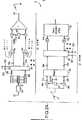
本発明の実施例を図4、図5および図7に示す。グローバルパイロット信号消去システム61の実施例を図4に示す。受信信号rは次のように表される。実 施 Examples of the present invention are shown in FIG. 4, FIG. 5, and FIG. An embodiment of the global pilot
r=αcp+βct+n (式2)
ここで、受信信号rは複素数であって、パイロット信号強度αとパイロット符号cpとを乗算したものに、トラヒック信号強度βとトラヒック符号ctとの積およびランダム雑音nとを加算したものである。この雑音nは全受信雑音を含み、干渉は他の全てのトラヒック信号を含む。受信信号rからグローバルパイロット信号を消去するために、このシステム61はパイロット符号α、すなわち
α≠β (式3)
の信号強度を導き出す必要がある。これは、グローバルパイロット信号がトラヒック信号よりも高い電力レベルで伝送されるからである。r = αcp + βct + n (Equation 2)
Here, the received signal r is a complex number, and is obtained by adding a product of the traffic signal strength β and the traffic code ct and a random noise n to a product of the pilot signal strength α and the pilot code cp. This noise n includes the total received noise, and the interference includes all other traffic signals. To eliminate the global pilot signal from the received signal r, the
Needs to be derived. This is because the global pilot signal is transmitted at a higher power level than the traffic signal.
時間領域で受信信号rを加算すると、式(2)は次のようになる。When the received signal r is added in the time domain, equation (2) becomes as follows.
Σr=αΣcp+βΣct+Σn (式4)
図4を参照すると、受信したベースバンド信号rは、パイロット信号消去システム61およびパイロット逆拡散器65に入力63され、この逆拡散器65により受信信号rからパイロット信号を逆拡散する。第1のミキサ67は、拡散の際に用いたパイロットpn符号の複素共役値cp*69を乗算することにより受信信号rを逆拡散し、次式の信号を生ずる。Σr = αΣcp + βΣct + Σn (Equation 4)
Referring to FIG. 4, the received baseband signal r is
Σrcp*=αΣcpcp*+βΣctcp*+Σncp* (式5)
複素共役値は符号のみが異なり互いに等しい実数部と虚数部とを有する一対の複素数の一つである。Σrcp* = αΣcpcp* + βΣctcp* + Σncp* (Equation 5)
The complex conjugate value is one of a pair of complex numbers having only real signs and imaginary parts that differ only in sign.
逆拡散ずみのパイロット信号71は第1の加算/ダンププロセッサ73に供給され、この信号を時間領域にわたって加算する。第1の加算/ダンププロセッサ73の出力Qsdlは次式で表される。The
Osdl=αL1+βΣctcp*+Σncp* (式6)
ここで、L1はパイロット拡散符号cpとパイロット拡散符号の複素共役値cp*との積をLチップにわたって加算した値である。Osdl = αL1 + βΣctcp* + Σncp* (Equation 6)
Here, L1 is a value obtained by adding the product of the pilot spreading code cp and the complex conjugate value cp* of the pilot spreading code over L chips.
加算/ダンププロセッサ73の出力Osdlは低域フィルタ75に供給される。低域フィルタ75は各信号成分の平均値を算定する。パイロット・トラヒック交差相関の平均値はゼロであり、したがって雑音nの平均値である。それゆえ、フィルタ処理75の後では、式(6)内の第2項および第3項はゼロになる。時間領域にわたる低域フィルタ75の出力Olpfは次の式で表される。The outputOsdl of the addition /
Olpf=αL (式7)
低域フィルタ75の出力Olpfは処理手段77に供給され、パイロット符号強度αを生ずる。処理手段77は低域フィルタ75の出力OlpfをLで除算することによりαを計算する。したがって、処理手段77の出力Opmは次の式で表される。Olpf = αL (Equation 7)
The outputOlpf of the low-
Opm=α
(式8)
パイロット拡散符号cp*複素共役値発生器69は複素共役値プロセッサ79に結合され、パイロット拡散符号cpを生じる。パイロット拡散符号cpは第2のミキサ81に入力され、トラヒック拡散符号ct*複素共役値発生器83の出力と混合される。この第2のミキサ81の出力から得られる積は第2の加算/ダンププロセッサ85に供給される。第2の加算/ダンププロセッサ85の出力Osd2はΣcpct*であり、第3のミキサ87でαと合成される。第3のミキサ87の出力89はαΣcpct*である。Opm = α
(Equation 8)
Pilot spreading code cp*
受信信号rもトラヒック信号逆拡散器91により逆拡散される。トラヒック信号逆拡散器91は、第4のミキサ93を用いて、受信信号rを発生器83からのトラヒック符号複素共役値ct*と混合することにより受信信号rを逆拡散し、次の信号を生じる。The received signal r is also despread by the
Σrct*=αΣcpct*+βΣctct*+Σnct* (式9)
トラヒック信号逆拡散器91の出力95は第3の加算/ダンププロセッサ97に供給される。第3の加算/ダンププロセッサ97の時間に対する出力Osd3は次のようになる。Σrct* = αΣcpct* + βΣctct* + Σnct* (Equation 9)
The
Osd3=Σrct*=βL2+αΣcpct*+Σnct* (式10)
ここで、L2はトラヒック信号拡散符号ctとトラヒック信号拡散符号の複素共役値ct*との積をLチップにわたって加算した値である。Osd3 = Σrct* = βL2 + αΣcpct* + Σnct* (Equation 10)
Here, L2 is a value obtained by adding the product of the traffic signal spreading code ct and the complex conjugate value ct* of the traffic signal spreading code over L chips.
第3の加算/ダンププロセッサ97の出力Osd3は、第3のミキサ87の出力89を減算する加算器99に供給される。加算器99の出力Oaddは次式で与えられる。The output Osd3 of the third addition /
Oadd=βL2+αΣcpct*+Σnct*−αΣcpct* (式11)
したがって、パイロット信号消去システム61の出力Oaddは、下式で単純化したとおり受信信号rマイナスパイロット信号に等しい。Oadd = βL2 + αΣcpct* + Σnct* −αΣcpct* (Equation 11)
Therefore, the output Oadd of the pilot
Oadd=βL2+Σnct*
(式12)
本発明は、所望トラヒック信号から不要なトラヒック信号(s)を消去するのに類似の手法を使う。トラヒック信号は他のトラヒック信号にとってはグローバルパイロット信号と同様に干渉となるが、トラヒック信号はデータで変調されており、したがって動的な性質を備えるので、不要トラヒック信号の消去はグローバルパイロット信号の消去とは異なる。グローバルパイロット信号が一定の位相を備えるのに対して、トラヒック信号ではデータ変調により絶えず位相が変わる。Oadd = βL2 + Σnct*
(Equation 12)
The present invention uses a similar technique to eliminate unwanted traffic signal (s) from the desired traffic signal. Although the traffic signal interferes with other traffic signals as well as the global pilot signal, since the traffic signal is modulated with data and thus has a dynamic nature, the elimination of the unnecessary traffic signal is equivalent to the erasure of the global pilot signal. And different. While the global pilot signal has a fixed phase, the traffic signal changes its phase constantly due to data modulation.
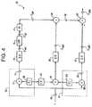
トラヒック信号消去システム101の実施例を図5に示す。上述のとおり、次式の受信信号rがこのシステムに入力103される。FIG. 5 shows an embodiment of the traffic
r=ψdcd+βct+n
(式13)
ここで、受信信号rは複素数であり、トラヒック符号信号強度Ψとトラヒック信号データdと消去すべき不要トラヒック信号のトラヒック符号cdとの積に、所望のトラヒック符号ctを乗算した所望のトラヒック符号強度βと、雑音nとを加算したものである。雑音nは全受信雑音を含み、干渉成分は他の全てのトラヒック信号とグローバルパイロット信号とを含む。受信信号rから不要なトラヒック信号(s)を消去するには、システム101は減算すべき不要トラヒック符号Ψの信号強度を導き出してデータdを推算する必要がある。r = ψdcd + βct + n
(Equation 13)
Here, the received signal r is a complex number, and the desired traffic code strength is obtained by multiplying the product of the traffic code signal strength Ψ, the traffic signal data d, and the traffic code cd of the unnecessary traffic signal to be eliminated by the desired traffic code ct. β and the noise n. The noise n includes the total received noise, and the interference component includes all other traffic signals and the global pilot signal. To eliminate the unnecessary traffic signal (s) from the received signal r, the
ψ≠d≠β (式14)
受信信号rを時間領域にわたって加算すると、式13は次式で表される。ψ ≠ d ≠ β (Equation 14)
When the received signal r is added over the time domain, Expression 13 is expressed by the following expression.
Σr=ψdΣcd+βΣct+Σn (式15)
図5を参照すると、受信ベースバンド信号rは、この受信信号rから所望トラヒック信号を逆拡散する所望トラヒック信号逆拡散器91に入力103される。所望トラヒック信号ミキサ93は受信信号rを、拡散の際に用いた所望トラヒックpn符号の複素共役値ct*と混合する。逆拡散ずみのトラヒック信号を加算/ダンププロセッサ97に加え、時間領域にわたって加算する。加算/ダンププロセッサ97の出力Osd3は次式で与えられる。Σr = ψdΣcd + βΣct + Σn (Equation 15)
Referring to FIG. 5, a received baseband signal r is
Osd3=Σrct*=βL2+ψdΣcdct*+Σnct* (式16)
図5に示したトラヒック信号消去システム101はn個の不要トラヒック信号キャンセラー1151〜115nを含む。この実施例は10個の(n=10)不要トラヒック信号キャンセラー1151〜11510を備えている。Osd3 = Σrct* = βL2 + ψdΣcdct* + Σnct* (Equation 16)
The traffic
不要トラヒック信号キャンセラー1151〜115nの各々は、第1のミキサ1171〜117nおよび不要トラヒック信号符号発生器1191〜119nを含む不要トラヒック信号逆拡散器1391〜139nと、第2のミキサ1331〜133nと、第1および第2の加算/ダンププロセッサ1211〜121nおよび1231〜123nと、難判定プロセッサ1251〜125nと、低域フィルタ1271〜127nと、処理手段1291〜129nと、第3のミキサ1311〜131nと、共役値プロセッサ1351〜135nと、可調整増幅器1371〜137nと、所望トラヒック信号符号発生器83とを備える。Each of the unnecessary traffic signal cancellers 1151 to 115n includes an unnecessary traffic signal despreader 1391 to 139n including a first mixer 1171 to 117n and an unnecessary traffic signal code generator 1191 to 119n, and a second mixer 1331 to 133n. First and second addition / dump processors 1211-121n and 1231-123n, difficulty determination processors 1251-125n, low-pass filters 1271-127n, processing means 1291-129n, and third mixers 1311-131n. , Conjugate value processors 1351 to 135n,
上述のとおり、受信信号rは不要トラヒック信号キャンセラー1151〜115nの各々に入力103される。不要トラヒック信号逆拡散器1391〜139nはこの入力103に接続され、受信信号rを各不要信号対応のトラヒック信号pn系列の複素共役値cdl*―cdn*と混合1171〜117nする。逆拡散ずみのトラヒック信号1391〜139nは、この信号を時間領域で加算する第1の加算/ダンププロセッサ1211〜121nに供給する。第1の加算/ダンプ1211〜121nの出力Osdlは次式で表される。As described above, the received signal r is
Osd1n=Σrcdn*=ψdL3+βΣctcdn*+Σncdn* (式17)
ここで、L3は不要トラヒック信号拡散符号cdnとの積でありcdn*は不要トラヒック信号拡散符号の複素共役値である。Osd1n = Σrcdn* = ψdL3 + βΣctcdn* + Σncdn* (Equation 17)
Here, L3 is the product of the unnecessary traffic signal spreading code cdn, and cdn* is the complex conjugate value of the unnecessary traffic signal spreading code.
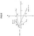
第1の加算/ダンププロセッサ1211〜121nの出力OsdInは難判定プロセッサ1251〜125nに供給する。この難判定プロセッサ1251〜125nは変調によるデータの位相偏移Φを判定する。難判定プロセッサ1251〜125nは逆拡散ずみシンボル値に最も近いQPSKコンステレーション位置dも判定する。出力 The output OsdIn of the first addition /
図6に示すとおり、難判定プロセッサ1251〜125nは信号の受信シンボルp0を四つのQPSKコンステレーション点x1、1、x−1、1、x−1、−1、x1、−1と比較する。マルチパスに起因するか無線周波数に起因するかに関わりなく、雑音や歪みによる伝送47中の劣化があるので、各受信シンボルp0を調べる必要がある。難判定プロセッサは受信シンボルp0から各象限までの四つの距離d1、d2、d3、d4を計算し、最短距離d2を選び、そのシンボルdに位置x−1、1を割当てる。また、難判定プロセッサは選択ずみのシンボル位置x−1、1に対応する位相に等しい位相量Φだけ当初の信号座標p0を位相逆回転(逆回転)する。当初のシンボル座標p0は放棄する。難 As shown in FIG. 6, the
難判定プロセッサ1251〜125nの位相出力Φは低域フィルタ1271〜127nに供給する。これら低域フィルタ1271〜127nは時間の経過とともに各信号成分の平均値を算定する。トラヒック信号相互間交差相関の平均値と雑音nの平均値はゼロである。したがって、時間の経過に伴う低域フィルタ1271〜127nの出力Qlpfnは次式で与えられる。位相 The phase output Φ of the
Olpfn=ψL (式18)
低域フィルタ1271〜127nの出力Qlpfnは処理手段1291〜129nに供給され、不要トラヒック信号符号強度Ψを抽出する。処理手段1291〜129nはフィルタ1271〜127nの出力QlpfnをLで除算することによりΦを推算する。Olpfn = ψL (Equation 18)
Outputs Qlpfn of the low-pass filters 1271-127n are supplied to processing means 1291-129n, and extract the unnecessary traffic signal code strength Ψ. The processing units 1291 to 129n estimate Φ by dividing the output Qlpfn of the
難判定プロセッサ1251〜125nのもう一つの出力はデータdである。これは図6に示すとおり距離d1、d2、d3、d4の最小値に対応するデータ点dである。第3のミキサ1311〜131nは不要トラヒック信号強度Ψを各データ値dと混合する。Another output of the
不要トラヒック信号拡散符号複素共役値発生器cdl*〜cdn*は複素共役値プロセッサ1351〜135nに結合され、不要トラヒック信号拡散符号cdl〜cdnを生じ、これら信号は第2のミキサ1331〜133nに入力され、所望トラヒック信号拡散符号複素共役値発生器ct*の出力と混合される。この積は第2の加算/ダンププロセッサ1231〜123nに供給される。第2の加算/ダンププロセッサ1231〜123nの出力Osd2nはΣcdnct*であり、可変増幅器1371〜137nに供給される。可変増幅器1371〜137nは、決定ずみの利得である第3のミキサ1311〜131nの出力に従って第3の加算/ダンププロセッサ1231〜123nの出力Osd2nを増幅する。Unwanted traffic signal spreading code complex conjugate value generators cdl* to cdn* are coupled to complex conjugate value processors 1351 to 135n to generate unnecessary traffic signal spreading codes cdl to cdn, which are input to second mixers 1331 to 133n. And mixed with the output of the desired traffic signal spreading code complex conjugate value generator ct* . This product is supplied to the second addition / dump processors 1231 to 123n. Outputs Osd2n of the second addition / dump processors 1231 to 123n are Σcdnct* , and are supplied to the
可変増幅器1371〜137nの出力1411〜141nは、所望トラヒック信号逆拡散器105の出力から可変増幅器1371〜137nの各々の出力を減算する加算器143に供給される。この出力Oは次式で与えられる。The
O=βL+ψdΣcdct*+Σnct*−ψdΣcdct*
(式19)
加算器143の出力O(また、不要トラヒック信号消去システム101の出力でもある)は受信信号rマイナス不要トラヒック信号に等しく、次のとおり簡略表示される。O = βL + ψdΣcdct* + Σnct* −ψdΣcdct*
(Equation 19)
The output O of the adder 143 (also the output of the unnecessary traffic signal elimination system 101) is equal to the received signal r minus the unnecessary traffic signal, and is simply represented as follows.
O=βL+Σnct*
(式20)
ここで、雑音nは受信信号から減算したトラヒック信号量に応じて変化する。O = βL + Σnct*
(Equation 20)
Here, the noise n changes according to the traffic signal amount subtracted from the received signal.
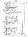
グローバルパイロット信号と不要トラヒック信号とを消去するもう一つの実施例145を図7に示す。前述のとおり、不要トラヒック信号消去システム101は所望トラヒック信号逆拡散器91と複数の不要トラヒック信号キャンセラー1151〜115nとを含む。このトラヒック信号消去システムは上述のパイロット信号消去システム61と並列に結合してあるが、所望トラヒック信号逆拡散器を備えていない。共通入力147をこれら両方のシステム101および61に接続し、これら両システム101および61からの出力OおよびOaddに共通の加算器149を接続してある。パイロット信号および不要トラヒック信号を所望のトラヒック信号から減算することによって、パイロット信号や複数の送信トラヒック信号による干渉のない出力151を生ずる。FIG. 7 shows another
以上、本発明の特定の実施形態を示して説明したが、当業者には本発明の原理や範囲を逸脱することなく多数の変更や修正が可能である。上述の説明は例示のためのものであって、特定の実施の態様に限定するものではない。Although specific embodiments of the present invention have been shown and described above, many changes and modifications can be made by those skilled in the art without departing from the principles and scope of the present invention. The descriptions above are intended to be illustrative, not limiting to particular embodiments.
第3世代モバイル通信システムのシステム容量拡大および費用効率改善に利用できる。利用 Can be used to expand system capacity and improve cost efficiency of third generation mobile communication systems.
17 B−CDMA通信システム
19 送信機
21 受信機
23 シグナルプロセッサ
25 音声および非音声信号
27 前向き誤り訂正符合器
33x,33y シンボル
39 複素乗算器
43 搬送波
45a,45b 合成器
47 受信広帯域信号
49a,49b 復調器
55a,55b QPSK信号
53 フィルタ
56 複素乗算器
57x,57y データ信号
59 シグナルプロセッサ
61 パイロット信号消去システム
63 システム入力
65 パイロット信号逆拡散器
67,93,87 ミキサ
73 加算/ダンププロセッサ
75 低域フィルタ
91 トラヒック逆拡散器
93 所望トラヒック信号ミキサ
101 トラヒック信号逆拡散器
1151・・・115n 不要トラヒック信号キャンセラ
145 複素共役値発生器17 B-CDMA Communication System 19 Transmitter 21
Claims (4)
Translated fromJapanese前記通信信号を受けるシステム入力(147)を含み、
前記所望のトラヒック信号から不要トラヒック信号を減算した差に等しい出力(O)を有するトラヒック信号消去システム(101)に前記システム入力(147)が入力(103)として入力されており、
前記所望のトラヒック信号からグローバルパイロット信号を減算した差に等しい出力(Oadd)を有し前記グローバルパイロット信号を除去するように入力(63)を信号処理するパイロット信号消去システム(61)にも前記システム信号入力(147)を前記入力(63)として入力し、
前記パイロット信号消去システム(61)の出力(Oadd)を前記トラヒック信号消去システム(101)の出力(O)から減算して前記消去システムの出力(151)を生ずる
消去システム。An erasure system for removing a selected signal from a desired traffic signal prior to decoding at a receiver receiving a communication signal from a transmitter (19) via a CDMA radio interface, comprising:
A system input (147) for receiving the communication signal;
The system input (147) is input as an input (103) to a traffic signal cancellation system (101) having an output (O) equal to the difference of the desired traffic signal minus the unwanted traffic signal;
A pilot signal cancellation system (61) that has an output (Oadd) equal to the difference of the desired traffic signal minus the global pilot signal and processes the input (63) to remove the global pilot signal. A signal input (147) is input as said input (63),
An erasure system that subtracts the output (Oadd) of the pilot signal erasure system (61) from the output (O) of the traffic signal erasure system (101) to produce the output (151) of the erasure system.
前記入力(63)に接続され加算出力(Osd1)を有するグローバルパイロット逆拡散器(65)と、
出力(Osd2)を有する所望トラヒック信号・グローバルパイロット信号間交差相関手段と
を含み、
前記グローバルパイロット逆拡散器(65)の出力(Osd1)が出力(Opm)を有するパイロット信号強度算定手段に接続され、
前記パイロット信号強度算定手段の出力(Opm)を前記交差相関手段の出力(Osd2)と乗算し、
前記乗算の出力が前記出力(Oadd)である
請求項1記載の消去システム。The pilot signal cancellation system (61) includes:
A global pilot despreader (65) connected to said input (63) and having an addition output (Osd1);
Means for cross-correlating the desired traffic signal and the global pilot signal having an output (Osd2),
An output (Osd1) of the global pilot despreader (65) is connected to a pilot signal strength calculating means having an output (Opm);
Multiplying the output (Opm) of the pilot signal strength calculating means with the output (Osd2) of the cross-correlation means,
2. The erasure system according to claim 1, wherein the output of the multiplication is the output (Oadd).
前記通信信号およびシステム出力(Oadd)を受ける入力(63)を含み、
各々が加算出力を有するグローバルパイロット信号逆拡散器(65)および所望トラヒック信号逆拡散器(91)に前記入力が接続されており、
所望トラヒック信号・グローバルパイロット信号交差相関手段をさらに含み、
前記グローバルパイロット信号逆拡散器(65)出力(Osd1)を出力(Opm)を有するパイロット信号強度算定手段に接続し、
前記パイロット信号強度算定手段の出力(Opm)を前記交差相関手段の出力(Osd2)と乗算し、
前記乗算の積を前記所望トラヒック信号逆拡散器(91)の加算出力(Osd3)から減算して前記グローバルパイロット信号の影響を免れた前記所望のトラヒック信号出力(Oadd)を出力する
グローバルパイロット信号消去システム(61)。A global pilot signal cancellation system (61) for a receiver for receiving a communication signal from a transmitter via a CDMA radio interface, said system removing said global pilot signal from a desired traffic signal prior to decoding. In (61),
An input (63) for receiving the communication signal and a system output (Oadd);
Said inputs are connected to a global pilot signal despreader (65) and a desired traffic signal despreader (91) each having an added output;
A desired traffic signal / global pilot signal cross-correlation means,
Connecting the global pilot signal despreader (65) output (Osd1) to pilot signal strength calculating means having an output (Opm);
Multiplying the output (Opm) of the pilot signal strength calculating means with the output (Osd2) of the cross-correlation means,
Global pilot signal cancellation for subtracting the product of the multiplication from the added output (Osd3) of the desired traffic signal despreader (91) to output the desired traffic signal output (Oadd) free from the influence of the global pilot signal. System (61).
出力(Olpf)を有する低域フィルタ(75)と、
前記低域フィルタ(75)に接続され前記グローバルパイロット信号強度(Opm)を抽出し出力するプロセッサ(77)と
をさらに含む請求項3記載のグローバルパイロット信号消去システム(61)。The means for extracting the global pilot signal strength comprises:
A low-pass filter (75) having an output (Olpf);
The global pilot signal cancellation system (61) according to claim 3, further comprising: a processor (77) connected to the low-pass filter (75) to extract and output the global pilot signal strength (Opm).
Applications Claiming Priority (1)
| Application Number | Priority Date | Filing Date | Title |
|---|---|---|---|
| US09/175,174US6498784B1 (en) | 1998-10-20 | 1998-10-20 | Cancellation of pilot and traffic signals |
Related Parent Applications (1)
| Application Number | Title | Priority Date | Filing Date |
|---|---|---|---|
| JP2000577778ADivisionJP3527204B2 (en) | 1998-10-20 | 1999-01-27 | Elimination of pilot and unwanted traffic signals in CDMA systems |
Related Child Applications (1)
| Application Number | Title | Priority Date | Filing Date |
|---|---|---|---|
| JP2005070794ADivisionJP4286802B2 (en) | 1998-10-20 | 2005-03-14 | Elimination of pilot and unwanted traffic signals in CDMA systems |
Publications (3)
| Publication Number | Publication Date |
|---|---|
| JP2004120782Atrue JP2004120782A (en) | 2004-04-15 |
| JP2004120782A5 JP2004120782A5 (en) | 2005-08-11 |
| JP4008407B2 JP4008407B2 (en) | 2007-11-14 |
Family
ID=22639248
Family Applications (5)
| Application Number | Title | Priority Date | Filing Date |
|---|---|---|---|
| JP2000577778AExpired - Fee RelatedJP3527204B2 (en) | 1998-10-20 | 1999-01-27 | Elimination of pilot and unwanted traffic signals in CDMA systems |
| JP2003375359AExpired - Fee RelatedJP4008407B2 (en) | 1998-10-20 | 2003-11-05 | Elimination of pilot and unwanted traffic signals in CDMA systems |
| JP2005070794AExpired - Fee RelatedJP4286802B2 (en) | 1998-10-20 | 2005-03-14 | Elimination of pilot and unwanted traffic signals in CDMA systems |
| JP2005289741AExpired - Fee RelatedJP4309388B2 (en) | 1998-10-20 | 2005-10-03 | Elimination of pilot and unwanted traffic signals in CDMA systems |
| JP2007188694ACeasedJP2007312418A (en) | 1998-10-20 | 2007-07-19 | Cancellation of pilot signal and unneeded traffic signal in cdma system |
Family Applications Before (1)
| Application Number | Title | Priority Date | Filing Date |
|---|---|---|---|
| JP2000577778AExpired - Fee RelatedJP3527204B2 (en) | 1998-10-20 | 1999-01-27 | Elimination of pilot and unwanted traffic signals in CDMA systems |
Family Applications After (3)
| Application Number | Title | Priority Date | Filing Date |
|---|---|---|---|
| JP2005070794AExpired - Fee RelatedJP4286802B2 (en) | 1998-10-20 | 2005-03-14 | Elimination of pilot and unwanted traffic signals in CDMA systems |
| JP2005289741AExpired - Fee RelatedJP4309388B2 (en) | 1998-10-20 | 2005-10-03 | Elimination of pilot and unwanted traffic signals in CDMA systems |
| JP2007188694ACeasedJP2007312418A (en) | 1998-10-20 | 2007-07-19 | Cancellation of pilot signal and unneeded traffic signal in cdma system |
Country Status (18)
| Country | Link |
|---|---|
| US (6) | US6498784B1 (en) |
| EP (4) | EP2088682A3 (en) |
| JP (5) | JP3527204B2 (en) |
| KR (1) | KR100424518B1 (en) |
| CN (3) | CN1822516A (en) |
| AT (3) | ATE396549T1 (en) |
| AU (4) | AU764714B2 (en) |
| BR (1) | BR9914658A (en) |
| CA (2) | CA2347207C (en) |
| DE (4) | DE69917060T2 (en) |
| DK (3) | DK1376889T3 (en) |
| EA (6) | EA005780B1 (en) |
| ES (3) | ES2221356T3 (en) |
| ID (1) | ID28838A (en) |
| IL (4) | IL142554A0 (en) |
| NO (3) | NO323536B1 (en) |
| SG (2) | SG141427A1 (en) |
| WO (1) | WO2000024135A1 (en) |
Families Citing this family (49)
| Publication number | Priority date | Publication date | Assignee | Title |
|---|---|---|---|---|
| US8352400B2 (en) | 1991-12-23 | 2013-01-08 | Hoffberg Steven M | Adaptive pattern recognition based controller apparatus and method and human-factored interface therefore |
| US7027490B2 (en)* | 1997-06-11 | 2006-04-11 | Intel Corporation | Method and apparatus for reducing spread spectrum noise |
| US6498784B1 (en)* | 1998-10-20 | 2002-12-24 | Interdigital Technology Corporation | Cancellation of pilot and traffic signals |
| US6859799B1 (en) | 1998-11-30 | 2005-02-22 | Gemstar Development Corporation | Search engine for video and graphics |
| US7904187B2 (en) | 1999-02-01 | 2011-03-08 | Hoffberg Steven M | Internet appliance system and method |
| WO2001050616A1 (en)* | 1999-12-30 | 2001-07-12 | Morphics Technology, Inc. | A configurable all-digital coherent demodulator system for spread spectrum applications |
| US7103906B1 (en) | 2000-09-29 | 2006-09-05 | International Business Machines Corporation | User controlled multi-device media-on-demand system |
| WO2002031701A2 (en) | 2000-10-11 | 2002-04-18 | United Video Properties, Inc. | Systems and methods for providing storage of data on servers in an on-demand media delivery system |
| CA2323164A1 (en)* | 2000-10-11 | 2002-04-11 | Ramesh Mantha | Method, system and apparatus for improving reception in multiple access communication systems |
| GB2369018A (en)* | 2000-11-10 | 2002-05-15 | Ubinetics Ltd | Control channel interference cancellation for a CDMA receiver |
| US6996159B2 (en) | 2001-05-17 | 2006-02-07 | Intel Corporation | Reducing spread spectrum noise |
| US7190749B2 (en) | 2001-06-06 | 2007-03-13 | Qualcomm Incorporated | Method and apparatus for canceling pilot interference in a wireless communication system |
| US8611311B2 (en) | 2001-06-06 | 2013-12-17 | Qualcomm Incorporated | Method and apparatus for canceling pilot interference in a wireless communication system |
| US7574723B2 (en)* | 2001-07-19 | 2009-08-11 | Macrovision Corporation | Home media network |
| US20030072282A1 (en)* | 2001-10-17 | 2003-04-17 | Ying-Chang Liang | Code division multiple access downlink receiver |
| US7236548B2 (en)* | 2001-12-13 | 2007-06-26 | Koninklijke Philips Electronics N.V. | Bit level diversity combining for COFDM system |
| US20030162573A1 (en)* | 2002-02-19 | 2003-08-28 | Jyhchau Horng | Down-link interference cancellation for high-data-rate channels in advanced digital wireless networks |
| US20070220580A1 (en)* | 2002-03-14 | 2007-09-20 | Daniel Putterman | User interface for a media convergence platform |
| KR100461543B1 (en) | 2002-10-14 | 2004-12-16 | 한국전자통신연구원 | Method and apparatus for sir measurement for multiple antenna, high data rate packet access system |
| US7283532B2 (en)* | 2002-10-25 | 2007-10-16 | Alcatel Lucent | Hierarchical scheduler architecture for use with an access node |
| US8931010B2 (en)* | 2002-11-04 | 2015-01-06 | Rovi Solutions Corporation | Methods and apparatus for client aggregation of media in a networked media system |
| US7493646B2 (en) | 2003-01-30 | 2009-02-17 | United Video Properties, Inc. | Interactive television systems with digital video recording and adjustable reminders |
| US7574691B2 (en)* | 2003-03-17 | 2009-08-11 | Macrovision Corporation | Methods and apparatus for rendering user interfaces and display information on remote client devices |
| JP2008501274A (en)* | 2004-05-28 | 2008-01-17 | コーニンクレッカ フィリップス エレクトロニクス エヌ ヴィ | Signal processing method and signal processor in OFDM system |
| US8086575B2 (en)* | 2004-09-23 | 2011-12-27 | Rovi Solutions Corporation | Methods and apparatus for integrating disparate media formats in a networked media system |
| US8422955B2 (en)* | 2004-12-23 | 2013-04-16 | Qualcomm Incorporated | Channel estimation for interference cancellation |
| US8406695B2 (en) | 2004-12-23 | 2013-03-26 | Qualcomm Incorporated | Joint interference cancellation of pilot, overhead and traffic channels |
| US8442441B2 (en) | 2004-12-23 | 2013-05-14 | Qualcomm Incorporated | Traffic interference cancellation |
| US8099123B2 (en)* | 2004-12-23 | 2012-01-17 | Qualcomm Incorporated | Adaptation of transmit subchannel gains in a system with interference cancellation |
| CN1798443B (en)* | 2004-12-29 | 2010-04-28 | 华为技术有限公司 | A Calculation Method of Bit Error Rate of Physical Channel |
| US7508864B2 (en)* | 2005-02-14 | 2009-03-24 | Intel Corporation | Apparatus and method of canceling interference |
| JPWO2006115227A1 (en)* | 2005-04-21 | 2008-12-18 | 株式会社アイ・ピー・ビー | Index word extraction device for survey documents |
| US8472877B2 (en) | 2005-10-24 | 2013-06-25 | Qualcomm Incorporated | Iterative interference cancellation system and method |
| US8385388B2 (en) | 2005-12-06 | 2013-02-26 | Qualcomm Incorporated | Method and system for signal reconstruction from spatially and temporally correlated received samples |
| US9467322B2 (en) | 2005-12-27 | 2016-10-11 | Rovi Solutions Corporation | Methods and apparatus for integrating media across a wide area network |
| US8607287B2 (en)* | 2005-12-29 | 2013-12-10 | United Video Properties, Inc. | Interactive media guidance system having multiple devices |
| US20070157240A1 (en)* | 2005-12-29 | 2007-07-05 | United Video Properties, Inc. | Interactive media guidance system having multiple devices |
| US9681105B2 (en) | 2005-12-29 | 2017-06-13 | Rovi Guides, Inc. | Interactive media guidance system having multiple devices |
| US7929551B2 (en)* | 2006-06-01 | 2011-04-19 | Rovi Solutions Corporation | Methods and apparatus for transferring media across a network using a network interface device |
| US7822399B2 (en) | 2007-05-11 | 2010-10-26 | Telefonaktiebolaget Lm Ericsson (Publ) | Image compensation for wireless receiver |
| US20090019492A1 (en) | 2007-07-11 | 2009-01-15 | United Video Properties, Inc. | Systems and methods for mirroring and transcoding media content |
| US7894555B2 (en)* | 2007-08-02 | 2011-02-22 | Telefonaktiebolaget Lm Ericsson (Publ) | IQ imbalance image suppression |
| US7986930B2 (en)* | 2007-08-02 | 2011-07-26 | Telefonaktiebolaget Lm Ericsson (Publ) | IQ imbalance image suppression in presence of unknown phase shift |
| US8601526B2 (en) | 2008-06-13 | 2013-12-03 | United Video Properties, Inc. | Systems and methods for displaying media content and media guidance information |
| US9014546B2 (en)* | 2009-09-23 | 2015-04-21 | Rovi Guides, Inc. | Systems and methods for automatically detecting users within detection regions of media devices |
| US20110072452A1 (en)* | 2009-09-23 | 2011-03-24 | Rovi Technologies Corporation | Systems and methods for providing automatic parental control activation when a restricted user is detected within range of a device |
| US8805418B2 (en) | 2011-12-23 | 2014-08-12 | United Video Properties, Inc. | Methods and systems for performing actions based on location-based rules |
| US9674563B2 (en) | 2013-11-04 | 2017-06-06 | Rovi Guides, Inc. | Systems and methods for recommending content |
| US10805870B1 (en) | 2019-03-26 | 2020-10-13 | Star Solutions International Inc. | Wireless communication management system and private electronic communication network |
Family Cites Families (44)
| Publication number | Priority date | Publication date | Assignee | Title |
|---|---|---|---|---|
| JPH0693670B2 (en)* | 1984-12-29 | 1994-11-16 | 京セラ株式会社 | Spread spectrum communication system |
| US5506864A (en)* | 1990-12-05 | 1996-04-09 | Interdigital Technology Corporation | CDMA communications and geolocation system and method |
| US5235612A (en)* | 1990-12-21 | 1993-08-10 | Motorola, Inc. | Method and apparatus for cancelling spread-spectrum noise |
| US5224122A (en)* | 1992-06-29 | 1993-06-29 | Motorola, Inc. | Method and apparatus for canceling spread-spectrum noise |
| US5465413A (en)* | 1993-03-05 | 1995-11-07 | Trimble Navigation Limited | Adaptive noise cancellation |
| US5363403A (en) | 1993-04-22 | 1994-11-08 | Interdigital Technology Corporation | Spread spectrum CDMA subtractive interference canceler and method |
| US5553062A (en) | 1993-04-22 | 1996-09-03 | Interdigital Communication Corporation | Spread spectrum CDMA interference canceler system and method |
| US5740208A (en)* | 1993-06-25 | 1998-04-14 | Roke Manor Research Limited | Interference cancellation apparatus for mitigating the effects of poor affiliation between a base station and a mobile unit |
| GB2279851B (en) | 1993-07-01 | 1997-10-01 | Roke Manor Research | Threshold cancellation means for use in digital mobile radio networks |
| JP2570967B2 (en)* | 1993-07-08 | 1997-01-16 | 日本電気株式会社 | CDMA receiver |
| JP2938337B2 (en) | 1994-03-09 | 1999-08-23 | 三菱電機株式会社 | Data demodulation circuit for spread spectrum communication |
| JPH0879130A (en) | 1994-09-01 | 1996-03-22 | Oki Electric Ind Co Ltd | Receiver and pilot signal elimination device |
| EP0700166B1 (en)* | 1994-09-02 | 2007-10-17 | Matsushita Electric Industrial Co., Ltd. | Modulation degree detecting device |
| US5724378A (en) | 1994-12-13 | 1998-03-03 | Nit Mobile Communications Network, Inc. | CDMA multiuser receiver and method |
| US5745485A (en) | 1995-06-19 | 1998-04-28 | Aloha Networks, Inc. | Dual code multiple access for wireless data networks |
| JP2798128B2 (en) | 1996-08-06 | 1998-09-17 | 日本電気株式会社 | CDMA multi-user receiver |
| US6067292A (en)* | 1996-08-20 | 2000-05-23 | Lucent Technologies Inc | Pilot interference cancellation for a coherent wireless code division multiple access receiver |
| JP3390900B2 (en)* | 1996-12-20 | 2003-03-31 | 富士通株式会社 | Interference canceller and provisional determination method |
| KR100204599B1 (en)* | 1996-12-21 | 1999-06-15 | 정선종 | Adaptive and mixed noise eliminating method |
| JP3326679B2 (en) | 1997-01-31 | 2002-09-24 | 沖電気工業株式会社 | CDMA receiver |
| IL120538A (en) | 1997-03-26 | 2000-11-21 | Dspc Tech Ltd | Method and apparatus for reducing spread-spectrum noise |
| JP3373755B2 (en)* | 1997-04-09 | 2003-02-04 | 株式会社鷹山 | Complex despreading processor |
| US6628701B2 (en)* | 1997-06-11 | 2003-09-30 | Intel Corporation | Method and apparatus for reducing spread spectrum noise |
| US6680928B1 (en)* | 1997-07-22 | 2004-01-20 | Ericsson Inc. | Communications system and method for multi-carrier orthogonal coding |
| SG77607A1 (en)* | 1997-08-26 | 2001-01-16 | Univ Singapore | A multi-user code division multiple access receiver |
| US6366607B1 (en)* | 1998-05-14 | 2002-04-02 | Interdigital Technology Corporation | Processing for improved performance and reduced pilot |
| JP3626852B2 (en) | 1998-05-29 | 2005-03-09 | Kddi株式会社 | Method and apparatus for synthesizing signals under diversity reception |
| JP2970656B1 (en)* | 1998-06-25 | 1999-11-02 | 日本電気株式会社 | DS-CDMA multi-user interference canceller |
| US6154443A (en)* | 1998-08-11 | 2000-11-28 | Industrial Technology Research Institute | FFT-based CDMA RAKE receiver system and method |
| JP3800382B2 (en)* | 1998-09-04 | 2006-07-26 | 富士通株式会社 | Propagation path estimation method and interference canceller in interference canceller |
| US6125137A (en)* | 1998-09-11 | 2000-09-26 | Motorola, Inc. | Apparatus and method for performing a signal search in a coherent wireless communication system |
| GB2341757B (en)* | 1998-09-21 | 2003-07-02 | Fujitsu Ltd | Code-division multiple access mobile comunications networks |
| US6498784B1 (en)* | 1998-10-20 | 2002-12-24 | Interdigital Technology Corporation | Cancellation of pilot and traffic signals |
| CN1134119C (en)* | 1998-10-27 | 2004-01-07 | 罗克马诺尔研究有限公司 | Method for improved extraction in CDMA system |
| US6333947B1 (en)* | 1998-11-25 | 2001-12-25 | Nortel Networks Limited | Interference cancellation system and method and CDMA receiver including an interference cancellation circuit |
| KR100343773B1 (en)* | 1999-06-28 | 2002-07-19 | 한국전자통신연구원 | Apparatus and method of partial parallel interference cancellation system for CDMA |
| US6404760B1 (en)* | 1999-07-19 | 2002-06-11 | Qualcomm Incorporated | CDMA multiple access interference cancellation using signal estimation |
| US6278726B1 (en)* | 1999-09-10 | 2001-08-21 | Interdigital Technology Corporation | Interference cancellation in a spread spectrum communication system |
| JP3371956B2 (en)* | 1999-11-09 | 2003-01-27 | 日本電気株式会社 | Interference canceller device |
| US6834043B1 (en)* | 2000-07-24 | 2004-12-21 | Motorola, Inc. | Method and device for exploiting transmit diversity in time varying wireless communication systems |
| US6768727B1 (en)* | 2000-11-09 | 2004-07-27 | Ericsson Inc. | Fast forward link power control for CDMA system |
| US7133353B2 (en)* | 2001-01-08 | 2006-11-07 | Telefonaktiebolaget Lm Ericsson (Publ) | CDMA system using quasi-orthogonal codes |
| US6751264B2 (en)* | 2001-07-27 | 2004-06-15 | Motorola, Inc. | Receiver and method therefor |
| US6819720B1 (en)* | 2002-06-28 | 2004-11-16 | Nortel Networks Limited | Noise cancellation in a predistortion architecture |
- 1998
- 1998-10-20USUS09/175,174patent/US6498784B1/ennot_activeExpired - Lifetime
- 1999
- 1999-01-27KRKR10-2001-7004934Apatent/KR100424518B1/ennot_activeExpired - Fee Related
- 1999-01-27DEDE69917060Tpatent/DE69917060T2/ennot_activeExpired - Lifetime
- 1999-01-27SGSG200800352-7Apatent/SG141427A1/enunknown
- 1999-01-27EAEA200301154Apatent/EA005780B1/ennot_activeIP Right Cessation
- 1999-01-27JPJP2000577778Apatent/JP3527204B2/ennot_activeExpired - Fee Related
- 1999-01-27EPEP09004606Apatent/EP2088682A3/ennot_activeWithdrawn
- 1999-01-27WOPCT/US1999/001883patent/WO2000024135A1/enactiveIP Right Grant
- 1999-01-27DKDK03018127Tpatent/DK1376889T3/enactive
- 1999-01-27DEDE1123584Tpatent/DE1123584T1/enactivePending
- 1999-01-27EAEA200300068Apatent/EA004419B1/ennot_activeIP Right Cessation
- 1999-01-27DEDE69938796Tpatent/DE69938796D1/ennot_activeExpired - Lifetime
- 1999-01-27EAEA200600592Apatent/EA200600592A1/enunknown
- 1999-01-27EAEA200501109Apatent/EA007355B1/ennot_activeIP Right Cessation
- 1999-01-27AUAU24801/99Apatent/AU764714B2/ennot_activeCeased
- 1999-01-27SGSG200301708Apatent/SG120924A1/enunknown
- 1999-01-27ATAT03018126Tpatent/ATE396549T1/ennot_activeIP Right Cessation
- 1999-01-27CACA002347207Apatent/CA2347207C/ennot_activeExpired - Fee Related
- 1999-01-27ILIL14255499Apatent/IL142554A0/enactiveIP Right Grant
- 1999-01-27ESES99904397Tpatent/ES2221356T3/ennot_activeExpired - Lifetime
- 1999-01-27EPEP03018126Apatent/EP1376888B1/ennot_activeExpired - Lifetime
- 1999-01-27DKDK03018126Tpatent/DK1376888T3/enactive
- 1999-01-27ESES03018127Tpatent/ES2329775T3/ennot_activeExpired - Lifetime
- 1999-01-27DKDK99904397Tpatent/DK1123584T3/enactive
- 1999-01-27ATAT99904397Tpatent/ATE266280T1/ennot_activeIP Right Cessation
- 1999-01-27CACA2568247Apatent/CA2568247C/ennot_activeExpired - Fee Related
- 1999-01-27CNCNA2006100550100Apatent/CN1822516A/enactivePending
- 1999-01-27ESES03018126Tpatent/ES2307857T3/ennot_activeExpired - Lifetime
- 1999-01-27DEDE69941098Tpatent/DE69941098D1/ennot_activeExpired - Lifetime
- 1999-01-27BRBR9914658-4Apatent/BR9914658A/ennot_activeApplication Discontinuation
- 1999-01-27CNCN200610095714Apatent/CN100583665C/ennot_activeExpired - Fee Related
- 1999-01-27EAEA200500247Apatent/EA006354B1/ennot_activeIP Right Cessation
- 1999-01-27EPEP03018127Apatent/EP1376889B1/ennot_activeExpired - Lifetime
- 1999-01-27EPEP99904397Apatent/EP1123584B1/ennot_activeExpired - Lifetime
- 1999-01-27IDIDW20010860Apatent/ID28838A/enunknown
- 1999-01-27CNCNB99812401XApatent/CN1251417C/ennot_activeExpired - Fee Related
- 1999-01-27EAEA200100371Apatent/EA003472B1/ennot_activeIP Right Cessation
- 1999-01-27ATAT03018127Tpatent/ATE436122T1/ennot_activeIP Right Cessation
- 2001
- 2001-04-11NONO20011878Apatent/NO323536B1/ennot_activeIP Right Cessation
- 2001-04-12ILIL142554Apatent/IL142554A/ennot_activeIP Right Cessation
- 2002
- 2002-10-08USUS10/266,408patent/US6603743B2/ennot_activeExpired - Lifetime
- 2003
- 2003-06-16USUS10/462,489patent/US6950411B2/ennot_activeExpired - Fee Related
- 2003-10-24AUAU2003257532Apatent/AU2003257532B8/ennot_activeCeased
- 2003-11-05JPJP2003375359Apatent/JP4008407B2/ennot_activeExpired - Fee Related
- 2005
- 2005-03-14JPJP2005070794Apatent/JP4286802B2/ennot_activeExpired - Fee Related
- 2005-09-23USUS11/234,768patent/US7751465B2/ennot_activeExpired - Fee Related
- 2005-10-03JPJP2005289741Apatent/JP4309388B2/ennot_activeExpired - Fee Related
- 2006
- 2006-03-01AUAU2006200879Apatent/AU2006200879B2/ennot_activeCeased
- 2006-05-10ILIL175551Apatent/IL175551A/ennot_activeIP Right Cessation
- 2007
- 2007-01-08NONO20070112Apatent/NO325092B1/ennot_activeIP Right Cessation
- 2007-07-19JPJP2007188694Apatent/JP2007312418A/ennot_activeCeased
- 2008
- 2008-01-21NONO20080404Apatent/NO20080404L/ennot_activeApplication Discontinuation
- 2008-11-06AUAU2008243149Apatent/AU2008243149B2/ennot_activeCeased
- 2010
- 2010-06-01ILIL206123Apatent/IL206123A0/enunknown
- 2010-06-25USUS12/823,407patent/US8369385B2/ennot_activeExpired - Fee Related
- 2013
- 2013-01-22USUS13/746,873patent/US8594157B2/ennot_activeExpired - Fee Related
Also Published As
Similar Documents
| Publication | Publication Date | Title |
|---|---|---|
| JP4286802B2 (en) | Elimination of pilot and unwanted traffic signals in CDMA systems | |
| HK1038450B (en) | Cancellation of pilot and unwanted traffic signals in a cdma system | |
| MXPA01003986A (en) | Cancellation of pilot and unwanted traffic signals in a cdma system | |
| HK1061612B (en) | Cancellation of pilot and unwanted traffic signals in a cdma system | |
| HK1135243A (en) | Cancellation of pilot and unwanted traffic signals in a cdma system | |
| HK1063111B (en) | Cancellation of pilot and unwanted traffic signals in a cdma system |
Legal Events
| Date | Code | Title | Description |
|---|---|---|---|
| A521 | Request for written amendment filed | Free format text:JAPANESE INTERMEDIATE CODE: A523 Effective date:20050117 | |
| A521 | Request for written amendment filed | Free format text:JAPANESE INTERMEDIATE CODE: A523 Effective date:20050314 | |
| A131 | Notification of reasons for refusal | Free format text:JAPANESE INTERMEDIATE CODE: A131 Effective date:20060306 | |
| A601 | Written request for extension of time | Free format text:JAPANESE INTERMEDIATE CODE: A601 Effective date:20060602 | |
| A602 | Written permission of extension of time | Free format text:JAPANESE INTERMEDIATE CODE: A602 Effective date:20060607 | |
| A521 | Request for written amendment filed | Free format text:JAPANESE INTERMEDIATE CODE: A523 Effective date:20060904 | |
| A02 | Decision of refusal | Free format text:JAPANESE INTERMEDIATE CODE: A02 Effective date:20061115 | |
| A521 | Request for written amendment filed | Free format text:JAPANESE INTERMEDIATE CODE: A523 Effective date:20070209 | |
| A521 | Request for written amendment filed | Free format text:JAPANESE INTERMEDIATE CODE: A821 Effective date:20070328 | |
| RD02 | Notification of acceptance of power of attorney | Free format text:JAPANESE INTERMEDIATE CODE: A7422 Effective date:20070328 | |
| RD04 | Notification of resignation of power of attorney | Free format text:JAPANESE INTERMEDIATE CODE: A7424 Effective date:20070521 | |
| A911 | Transfer to examiner for re-examination before appeal (zenchi) | Free format text:JAPANESE INTERMEDIATE CODE: A911 Effective date:20070601 | |
| A521 | Request for written amendment filed | Free format text:JAPANESE INTERMEDIATE CODE: A523 Effective date:20070511 | |
| TRDD | Decision of grant or rejection written | ||
| A01 | Written decision to grant a patent or to grant a registration (utility model) | Free format text:JAPANESE INTERMEDIATE CODE: A01 Effective date:20070817 | |
| A61 | First payment of annual fees (during grant procedure) | Free format text:JAPANESE INTERMEDIATE CODE: A61 Effective date:20070829 | |
| FPAY | Renewal fee payment (event date is renewal date of database) | Free format text:PAYMENT UNTIL: 20100907 Year of fee payment:3 | |
| R150 | Certificate of patent or registration of utility model | Free format text:JAPANESE INTERMEDIATE CODE: R150 | |
| FPAY | Renewal fee payment (event date is renewal date of database) | Free format text:PAYMENT UNTIL: 20100907 Year of fee payment:3 | |
| FPAY | Renewal fee payment (event date is renewal date of database) | Free format text:PAYMENT UNTIL: 20110907 Year of fee payment:4 | |
| FPAY | Renewal fee payment (event date is renewal date of database) | Free format text:PAYMENT UNTIL: 20120907 Year of fee payment:5 | |
| FPAY | Renewal fee payment (event date is renewal date of database) | Free format text:PAYMENT UNTIL: 20130907 Year of fee payment:6 | |
| R250 | Receipt of annual fees | Free format text:JAPANESE INTERMEDIATE CODE: R250 | |
| R250 | Receipt of annual fees | Free format text:JAPANESE INTERMEDIATE CODE: R250 | |
| R250 | Receipt of annual fees | Free format text:JAPANESE INTERMEDIATE CODE: R250 | |
| R250 | Receipt of annual fees | Free format text:JAPANESE INTERMEDIATE CODE: R250 | |
| LAPS | Cancellation because of no payment of annual fees |