JP2004118824A - Storage system for content distribution - Google Patents
Storage system for content distributionDownload PDFInfo
- Publication number
- JP2004118824A JP2004118824AJP2003072916AJP2003072916AJP2004118824AJP 2004118824 AJP2004118824 AJP 2004118824AJP 2003072916 AJP2003072916 AJP 2003072916AJP 2003072916 AJP2003072916 AJP 2003072916AJP 2004118824 AJP2004118824 AJP 2004118824A
- Authority
- JP
- Japan
- Prior art keywords
- data
- file
- storage
- storage device
- master
- Prior art date
- Legal status (The legal status is an assumption and is not a legal conclusion. Google has not performed a legal analysis and makes no representation as to the accuracy of the status listed.)
- Granted
Links
Images


Classifications
- G—PHYSICS
- G06—COMPUTING OR CALCULATING; COUNTING
- G06F—ELECTRIC DIGITAL DATA PROCESSING
- G06F16/00—Information retrieval; Database structures therefor; File system structures therefor
- G06F16/10—File systems; File servers
- G06F16/18—File system types
- G06F16/182—Distributed file systems
- G06F16/184—Distributed file systems implemented as replicated file system
- Y—GENERAL TAGGING OF NEW TECHNOLOGICAL DEVELOPMENTS; GENERAL TAGGING OF CROSS-SECTIONAL TECHNOLOGIES SPANNING OVER SEVERAL SECTIONS OF THE IPC; TECHNICAL SUBJECTS COVERED BY FORMER USPC CROSS-REFERENCE ART COLLECTIONS [XRACs] AND DIGESTS
- Y10—TECHNICAL SUBJECTS COVERED BY FORMER USPC
- Y10S—TECHNICAL SUBJECTS COVERED BY FORMER USPC CROSS-REFERENCE ART COLLECTIONS [XRACs] AND DIGESTS
- Y10S707/00—Data processing: database and file management or data structures
- Y10S707/99951—File or database maintenance
- Y10S707/99952—Coherency, e.g. same view to multiple users
- Y10S707/99953—Recoverability
- Y—GENERAL TAGGING OF NEW TECHNOLOGICAL DEVELOPMENTS; GENERAL TAGGING OF CROSS-SECTIONAL TECHNOLOGIES SPANNING OVER SEVERAL SECTIONS OF THE IPC; TECHNICAL SUBJECTS COVERED BY FORMER USPC CROSS-REFERENCE ART COLLECTIONS [XRACs] AND DIGESTS
- Y10—TECHNICAL SUBJECTS COVERED BY FORMER USPC
- Y10S—TECHNICAL SUBJECTS COVERED BY FORMER USPC CROSS-REFERENCE ART COLLECTIONS [XRACs] AND DIGESTS
- Y10S707/00—Data processing: database and file management or data structures
- Y10S707/99951—File or database maintenance
- Y10S707/99956—File allocation
- Y10S707/99957—Garbage collection
Landscapes
- Engineering & Computer Science (AREA)
- Theoretical Computer Science (AREA)
- Data Mining & Analysis (AREA)
- Databases & Information Systems (AREA)
- Physics & Mathematics (AREA)
- General Engineering & Computer Science (AREA)
- General Physics & Mathematics (AREA)
- Information Retrieval, Db Structures And Fs Structures Therefor (AREA)
Abstract
Translated fromJapaneseDescription
Translated fromJapanese【発明の属する技術分野】
本発明は一般にデータ処理システムに係わり、特にプライマリー記憶システムから数台のセカンダリー記憶システムへブロックレベルのI/Oデータを転送することが可能な記憶システムに関する。ファイルシステムの形式のデータロケーション情報は、別個にセカンダリー記憶システムのユーザに転送される。
【従来の技術】
昨今のように大型の記憶システムが利用出来るようになり、またインターネットを経由してこのような記憶システムに容易にアクセスできるようになると、例えば、エンタテインメントや教育の両面で、リアルタイムでビデオを見るなどのアプリケーションへの要求が出てくる。例えば、通信媒体としてのインターネットの利用により、ビデオファイルを事実上世界中のどこにでも転送することが可能になる。しかしながら、多くのユーザがさらに大きい記憶システムを利用できるようにすると、それに付随して問題が起こる。それは少なくとも多くのユーザがほぼ同時に同じファイルにアクセスしようとした時に当然発生する、ボトルネックの結果として起こる性能低下である。
一つの解決方法は、異なった場所に複数のデータセンターを設置し、ユーザからのアクセス負荷を分散させることである。これにより複数のユーザは多くの場所の一箇所で(ビデオ)ファイルにアクセスすることが出来る。ビデオファイル(映画)における映画スタジオのようなプライマリーロケーションは、ファイルを全てのデータセンターに配布することが出来る。
しかしながら、ビデオファイルは通常はオペレイティングシステムのファイルシステムで管理される。ビデオサーバのようにオペレイティングシステム上で稼働しているアプリケーションは、ビデオをアクセスの便宜上ファイルとして取り扱う。一般に、ビデオファイルの転送には、TCP/IPネットワークを経由して一つのサーバから他のサーバへファイルをコピーするために「ファイルトランスファープロトコル−File transfer Protocol」(FTP)のようなファイルレベルのI/Oを使用する。このプロトコルは、データがファイルシステム上に記憶されていることを想定している。
しかしながら、ファイルに基づくデータ転送方法は、しばしばファイルシステムの大きなオーバヘッドによる、低いデータ転送速度になる欠点がある。ファイルシステムとしては、論理「ボリューム」が、通常は多数のディスクデバイスによる、記憶空間の予め定められた部分にマップする、論理ファイル管理システムがしばしば用いられる。ファイルの読み出し、および/あるいは書き込みには、ファイルシステムは、また、ファイルのメタデータ、しばしばボリューム上のどこにファイルが記憶されているかを識別するファイルを記述している情報、およびファイル名、サイズ、最後にアクセスされた時刻等の関連属性、を読み書きする。メタデータは、また、ボリューム上にも記憶されるので、ファイル上で読み出しおよび/あるいは書き込み動作を伴うメタデータ動作は、CPUの能力とI/Oのバンド幅を低下させる。これがファイル転送に基づく転送速度が低い理由である。
ファイル配布サービスを提供することができるサービスがある。AkamaiとDigital Islandはこのようなサービスのいくつかの例であり、上述のようなファイルベースのデータ転送方法を通常は用いるので、さきに説明した問題の影響を受ける。ブロックレベルのデータ転送を提供するリモートコピー方法もある。この転送方法は米国特許5,742,792に記述されている。しかしながら、用いられている転送方法はファイルシステムを使用するアプリケーションに用いるようには構成されていない。このことは、たとえデータコピーが行なわれたとしても、アプリケーションやファイルシステムは転送されたデータを処理できない、ことを意味する。
【発明が解決しようとする課題】
本発明はプライマリーあるいはマスター記憶システムから多数のセカンダリー記憶システムに配布されたデータの複数のコピーを持つプロセッシングシステムに対するものである。本発明は、記憶システム間でのデータ転送にはブロックレベルI/Oを用いさせながら、サーバ上で実行しているアプリケーションに、記憶システムに対してファイルレベルI/Oアクセスをさせることができる、システムと方法と提供する。
【課題を解決するための手段】
本発明では、プロセッシングシステムは2台あるいはそれ以上のデータセンタを含む。プライマリーデータセンタは、マネージメントコンソール、少なくとも1台のコンテンツマネージャ、オリジナルデータを記憶するための記憶システムを持ち、さらにアプリケーションサーバを持っていることもある。他のデータセンタはアプリケーションサーバと記憶システムを含む。プライマリーデータセンタでは、マネージメントコンソール、コンテンツマネージャ、およびもしあるならば、アプリケーションサーバは、第1のネットワークで相互に交信が可能なように接続され、そして関連する記憶システムに対しては第2のネットワークで接続されている。 プライマリーデータセンタの記憶システムに保持されているオリジナルデータは、他のデータセンタにおける残りの(セカンダリー)記憶システムにミラーされる。
プライマリーデータセンタの記憶システムと他のデータセンタの記憶システムは、第3のネットワークを経由して接続される。マネージメントコンソールとコンテンツマネージャは、それに対するデータアクセスのためにプライマリー記憶システムに結合され、アプリケーションサーバはアクセスのためにセカンダリー記憶システムの1台ないしは別の1台に接続する。データセンタで実行しているアプリケーション処理はファイルレベルのI/Oリクエストを行う一方、記憶システムにより制御される記憶媒体へのアクセスはブロックレベルI/Oを用いる。
マネージメントコンソールを通してのユーザインプット(例えばシステムアドミニストレータ)に対応して、コンテンツマネージャはシステムを構成するように動作する。コンテンツマネージャもまた、プライマリー記憶システム上のファイルのデータの位置を識別するデータ構造を生成し、データを記憶する。
データへの変更(削除、変更など)は、記憶媒体上で変更されたファイルと変更された位置を識別するために、データ構造への変更によって反映される。変更されたデータと対応するデータ構造は、第2のネットワーク上のデータ通信を通して、プライマリー記憶システム上で実行するリモートコピー処理により、セカンダリー記憶システムでも利用可能になる。セカンダリー記憶システムが保持する(ミラー化された)データに対する変更をアプリケーションサーバが知ることが出来るように、コンテンツマネージャのデータ構造とアプリケーションサーバは同期化される。
【発明の実施の形態】
本発明によると、プライマリーあるいはマスターデータセンタはプライマリー処理機構とデータのマスターコピーが保持されている記憶システムを含んでいる。データにはデータの場所を識別するデータ構造(ディレクトリリストやiノードリストなど)が記憶されている。定期的に、データに対しデータの変更(削除や修正など)が行われる。変更は、データを含んでいる記憶媒体の以前には未使用のエリアに書き込まれる。データの変更が終わると、変更したデータの場所を識別するためにデータ構造の修正が行われる。つぎに、変更したデータとデータ構造はリモートコピーキュー上に置かれる。リモートコピープロセスは、最後のスキャンの後に行われた変更をみるために、定期的にリモートコピーキューをスキャンし、もし変更されたデータが見つかると、変更されたデータは、関連する修正されたデータ構造とともに、1台ないしはそれ以上のセカンダリー記憶システムにコピーされ、セカンダリー記憶システムに結合されたアプリケーションサーバで利用できるようになる。
プライマリー処理機構は、変更されたデータとそれに伴う修正されたデータ構造がセカンダリー記憶システムに受け取られたとことを確認すると、アプリケーションサーバにメッセージを送る。アプリケーションサーバがメッセージを受け取ると、データが変更されたことを告示する。アプリケーションサーバは、関連した記憶装置から修正されたデータ構造を検索し、古い(変更されていない)データではなく更新されたデータが使用されるようにする。
システム構成
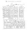
図を見てみると、図1は、本発明を用いた、参照番号10が割り当てられた、基本的なデータプロセシングシステムの説明である。図1が示すように、データプロセシングシステム10は、ここではデータセンタ12Aと12Nで示される、複数のデータセンタを含むことができる。プライマリーデータセンタ12Aは、マネージメントコンソール14、コンテンツマネージャ16を含み、アプリケーションサーバ18と記憶システム22Aを含んでも含まなくてもよい。データセンタ12Nのような他のデータセンタ12は、それぞれが記憶システム22Nを含むアプリケーションサーバである。
マネージメントコンソール14、コンテンツサーバ16およびデータセンタ12Aのアプリケーションサーバ18は、例えばローカルエリアネットワーク(LAN―1)を経由して、記憶システム22Aと接続する。同様に、データセンタ12Nのアプリケーションサーバ18は、LAN接続により関連する記憶装置22Nに接続する。以下に詳細を説明するように、各記憶システム22Aと22Nは、ブロックI/Oを実行するためのディスクコントローラ24、とリモートコピー(RC)プロセス26、28を含む。さらに、各ディスクコントローラは、以下に説明するペアテーブル30と呼ばれるデータ構造を保持している。
ディスクコントローラ24は、記憶媒体34と36に結合し、その1個ないしはそれ以上の「ボリューム」が、記憶媒体34と36を使う磁気ディスク記憶ユニットに位置づけされている、「論理」記憶装置を優先的に実行する。このような論理記憶装置は、記憶媒体にアクセスするためにブロックレベルI/Oを用いるデータセンタ12のサーバ(例えば、アプリケーションサーバ18やコンテンツマネージャ16など)からのI/Oリクエストに応答しやすくする。(従来技術と同様に、例えばサーバ18上で実行する、アプリケーション処理は、サーバのファイルシステムにファイルレベルI/Oリクエストを発行する。順に、ファイルシステムは、記憶システム24にブロックレベルI/Oリクエストとしてリクエストを発行する。記憶システムは必ずしもデータ構造を理解するわけではないが、ブロックレベルで変更される部分は認識することが出来る。本発明によれば、これにより、データセンタ12Aの記憶システム24は、これらの変更を他のデータセンタ12へ送ることが出来る。)マスターボリューム34は、システムの全てのデータのマスターコピーを受け取り保持する。RCプロセス28を使用して、データセンタ12Aのディスクコントローラ24は、そのデータと、そのデータに対するその後の変更を、他のデータセンタ12の複製されたボリューム36にコピーする。このようにして、複製されたボリューム36はマスターボリューム34のデータをミラーする。
記憶媒体34と36へのアクセスを開始させるブロックレベルI/Oのリクエストを受け取るため、論理記憶装置が、記憶システム22のディスクコントローラ24によって実施される。コンテンツマネージャ16は、記憶媒体上のファイルにアクセスするためにブロックレベルI/Oに変換する、ファイルシステムに対してファイルレベルI/Oリクエストを用いて、ファイルを探し出すために必要なデータ構造を保持する。マネージメントコンソール14は、記憶システム22の記憶媒体上へのファイルの配置を含めて、システム10を構成する手段を提供する。
図1が示すように、アプリケーションサーバ18は、コンテンツマネージャに、ローカルエリアネットワーク(LAN2)接続、あるいはインターネットのようなワイドエリアネットワーク(WAN1)接続により、通信可能に接続されていることに注意が必要である。記憶システム22は、別個に、インターネットあるいは他のネットワーク接続でよいワイドエリアネットワーク(WAN2)を用いて、相互に接続される。マスターボリューム34上に保持されているデータイメージに変更が加えられると、これらの変更は記憶装置の使用されていないエリアに書き込まれる。
つぎに、そのデータを探し出すためにファイルシステムにより用いられている各種のファイル構造が修正され、そして修正されたファイル構造も記憶装置に書き込まれる。得られたデータイメージやファイル構造の変更は、後で、記憶システム22AからのブロックI/Oレベルにおける複製されたボリューム36に対する記憶媒体34から、他の記憶システム22BにWAN2接続を用いてコピーされる。また、その変更されたデータに対して必要なパスは、ファイルレベルI/Oフォーマットで、LAN2とWAN1のコミュニケーションパスを用いて、コンテンツマネージャ16からアプリケーションサーバ18に送られる。(ボブ:必要なパスとファイルレベルI/Oフォーマットはどういう意味なの?私はこのステップの意味が分からない。コンテンツマネージャは、LANとWAN1を経由して、メッセージをアプリケーションサーバへ送り、そしてメッセージはアプリケーションサーバのメモリーにあるキャッシュデータをフラッシュ(言い換えると、無効にする)するために用いられ、その結果アプリケーションサーバは、セカンダリー記憶システムでは新しいデータの代わりに旧いデータを使用することが無い。)
さらに図1が示すように、マネージメントコンソールは、コンフィギュレーションマネージャプロセス14a、ファイル更新プロセス14b、コンフィギュレーション変更プロセス14c、および更新ファイルチェックプログラム14dを実行する、あるいは実行することが可能である。これらのプロセスは、見て分かるように、ファイルレベルI/Oアクセスのために、ファイル構造を構成したり変更したりするための、以下で説明する他の機能を遂行するとともに、グローバルマウントポイントテーブル14eを管理し保持する。
コンテンツマネージャはアプリケーションプロセス、マスターファイルシステム、記憶システム22A上の各ファイル記憶装置を記述するメタデータを保持するように動作するマウントクライアント、ローカルマウントポイントテーブル、および更新されたiノードリストを実行する(あるいは実行することが出来る)。アプリケーションサーバは、それぞれアプリケーション、クライアントファイルシステム、およびなかんずく、記憶システム22のデータにファイルレベルI/Oアクセスをするためのメタデータやローカルマウントポイントテーブルを使用するように動作するマウントクライアントを実行する。
特定のシステムアーキテクチャは、代表的なものであって、この分野で熟練した人にとって、他のシステム設計が使用できると言うことは明らかである。たとえば、アプリケーションは、記憶システム22により保持されているデータにアクセスするようにファイルサーバを通して動作するアプリケーションサーバ上で実行してもよい。もしそうであるならば、ファイルサーバ上で、記憶システム上のファイルを読むようにアプリケーションサーバは実行されるので、アプリケーションサーバはクライアントファイルシステムをインストールする必要がない。
テーブル
上記に示すように、マネージメントコンソール14、コンテンツマネージャ16、およびアプリケーションサーバ18は、本発明を実施するに際し、各種のデータ構造やテーブルを保持する。これらのテーブルの説明を以下に示す。
グローバルマウントポイントテーブル
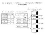
グローバルマウントポイントテーブル14eはマネージメントコンソール14により保持され、システム構成の情報を含んでいる。図2はグローバルマウントポイントテーブルの例を示す。図2が示すように、テーブルは、列40に構成名(例えば、CONF1、...、CONFm)を含む。各構成においては、コラム42に表示されるマウントポイント(/mnt1、...、mntm)とマスターファイルシステムのサーバ名(コラム44)がある。コラム46、48と50は、それぞれマスターファイルシステムにより管理されるファイルを使用するサーバ、ボリュームのリスト、およびサーバとボリュームの間のマッピングを記載している。マウントポイントは、どこにサーバがボリュームをマウントするかを識別するために使用される。マッピングは、サーバがどのボリュームを使用するかを示す。記憶システムとボリュームの識別子は記憶システムでのボリュームを指定する。
ファイルのいくつかのセットは特定のデータセンタへコピーされ、ファイルの他のセットは他のデータセンタへコピーされるとような場合がある。これが多くの構成がある理由である。各構成は、互いに異なっている、それぞれのデータセットを識別する。
ローカルマウントポイントテーブル
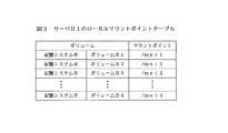
図3に示されるのがローカルマウントポイントテーブルであり、その一つはコンテンツマネージャ16にあり、システムの各アプリケーションサーバ16にある。ローカルマウントポイントテーブルは、どのボリュームをユニット(コンテンツマネージャまたはサーバ)がマウントするかについての情報を含んでいる。図3に示すように、サーバB1は記憶システムBとボリュームB1により指定されたボリュームをディレクトリ/mnt1にマウントする。ローカルマウントポイントテーブルはコンフィギュレーションマネージャプロセス14aにより生成され、配布される。
ペアテーブル
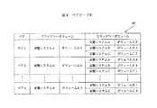
ペアテーブル30はディスクコントローラ24により管理され、どのボリュームが他のどのボリュームによりミラーされているか、また、どのボリュームがどの記憶システムと関連しているかというような情報を含んでいる。ペアテーブルの構造と内容の例を図4に示す。図では、ペアテーブル30‘は、コラム56、59と60のそれぞれが、ペアの名称、ペアの名称に関連したプライマリーボリュームの識別、1つないしはそれ以上のセカンダリーボリュームを含むことを示している。ペアの名称は、基本的にはグローバルマウントポイントテーブルの構成名に対応している。
プライマリーボリュームはオリジナルファイルを含むボリュームであり、コンテンツマネージャ16のマスターファイルシステムプロセスにより管理される。セカンダリーボリュームはプライマリーボリュームをミラーし、プライマリーボリュームのデータの複製を保持する。セカンダリーボリュームはアプリケーションサーバにより使用される。
ディレクトリリスト
ディレクトリリストはテーブルであって、ファイルシステムの各ディレクトリに一つ存在するものである。ディレクトリリストは、ディレクトリの各ファイルを、ファイルの各々のiノード番号とともに識別する情報を含んでいる。図5はディレクトリリストの例であって、例とするディレクトリabcが、ファイル1、ファイル2、...、ファイルnのファイルと、関連するiノード番号の1、2、...、nを識別することを示している。
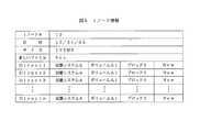
Iノードインフォメーション
ファイルレベルのシステムにおいては一般的であるが、iノードはファイルシステムの各ファイルに対して存在し、ファイルに関連する属性だけでなく、対応する記憶媒体34または36上のファイルを探し出すための情報も含んでいる。図6は、代表的なiノード情報を示す図であって、ファイルがiノード番号10を持ち、ファイル属性がファイルが最後に修正されたときのデータ、ファイルサイズ、「新ファイル」フラッグ、ディレクトリのリスト(「Direct」)のエントリーを含むことを示している。新ファイルフラッグはマスターファイルシステムで使用され、ファイルがオープンされたときにファイルが存在するか否かを示す。
ディレクトリエントリー(例えば、Direct1、Direct2など)は、記憶システム上でファイルを形成する各種のボリュームデータの位置を識別する。各ディレクトリエントリーは、それに関連して、その位置がファイルの現在のiノードにより使用されているか否かを示す「新」フラグを持つ。このフラグに関する詳細を以下に説明する。
例えば、このように、iノード番号10を持つファイルは、12/31/05に最新の更新がされ、大きさが100MBで、その構成部分は記憶システムAのボリュームA1にあるブロック1、2、...、nにある。
図7Aと図7Bは、ファイルをボリュームに記憶させる際の、ファイル、ディレクトリリスト、およびiノード情報の間の関係について図示している。
図7Aは、ファイルは容易にビデオファイルや他のファイルであってもよいのだが、テキストを含んでいるファイルを説明する。図7Bは、「ファイル3」というファイル名を持つファイルが「10」のiノードを持つことを示している。番号10のiノードは、ファイルを構成するデータのパーツが記憶媒体上、すなわち記憶システムAのボリュームA1にある。
更新されたiノードリスト
更新されたiノードリストは、最後のファイル更新がされた後で、どのファイルが更新あるいは生成されたかの情報を含むテーブルである。更新されたファイルに関連するiノードもこのテーブルに含まれている。図8は更新されたiノードリストの例である。ファイルネームコラムは、ファイルを識別し、「新iノード番号」は(更新された)ファイルに割り当てられたiノードを識別する。
利用可能なブロックリスト
利用可能なブロックリストは、各マスターボリューム43のどのロケーションが使用され、どのロケーションが使用可能かの情報を含むテーブルである。図9は利用可能なブロックリストの例である。この例では、記憶システムAのボリュームA1のブロック1の利用可能フラグ(No/Yes)はNoである。これは、このロケーションが何らかのファイルあるいはメタデータを記憶するために使用されていることを意味する。一方、同じボリュームのブロック3は、新しいファイルあるいは更新されたファイルを記憶するために使用可能である。
利用可能なiノードリスト
利用可能なブロックリストと同様に、利用可能なiノードリストは、どのiノード番号が使用され、どれが利用可能であるかを識別するテーブルである。図10はリストの例である。iノード番号の利用可能フラグがYesの場合は、そのiノード番号は利用可能である。それがNoの場合は、iノード番号はファイルを識別するために使用されている。
開かれたiノードリスト
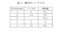
開かれたiノードリストは、どのファイルがアプリケーションにより現在使用されている(すなわち、開かれている)かの情報を含んでいるテーブルである。図11はそのようなリストの例である。リストは、開かれたファイルの識別子としてのファイル記述子を含んでいる。
いくつかのファイルシステムと同様に、アプリケーションがファイルを開くと、ファイルシステムはファイル記述子をファイルオープンに対して割り当てる。その後は、アプリケーションは、ファイルが開かれている間は、このファイル記述子を使用する。この例では、ファイル記述子1はiノード番号4を持つ関連したファイルにより使用されている。一方、ファイル記述子3はどのアプリケーションによっても使用されていないので、従って、使用可能である。
マネージメントコンソール
マネージメントコンソールは、たとえば、システムを構成し、そして時刻に合わせファイル更新を提供するシステムアドミニストレータに対する、グラフィックユーザインタフェース(GUI)を提供するプロセッサーユニットである。たとえファイルがコンテンツマネージャにより更新されても、その内容は、マネージメントコンソールからタイミングを伝えなくては、アプリケーションサーバには見えない。
GUI
マネージメントコンソール14は、一つの(例えば、システムアドミニストレータ)構成変更が、マネージメントコンソール上でマウントポイントアップデート処理を実行するための、GUIコールになるように、グラフィックユーザインタフェース(GUI:図示なし)を駆動するように動作する。
さらに、GUIは時刻を指定したファイルの更新の手段を、システムアドミニストレータに提供することが出来る。アドミニストレータは構成名を指定することが出来、そしてOKボタンを押すことでコンテンツマネージャにタイミングを指示できる。どのファイルが、指定の構成のために更新されたかを容易に理解させるために、GUIスクリーン(図示されず)は更新されたファイルのリストを提供することが出来る。GUIにより呼び出されると、更新ファイルチェックプログラム14d(図1)はこのリストを提供する。
ファイル更新プロセス
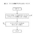
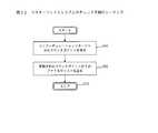
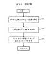
上記に示されたように、このプロセスはコンフィギュレーションマネージャプロセス14aのGUIにより呼ばれる。ファイル更新プロセス(14b)は、アプリケーションサーバ18に送られるべき更新されたファイルの識別を要求するために、コンテンツマネージャ16と交信する。図12はファイル更新プロセス14aが取るステップを示している。それはコンテンツマネージャ上で実行しているマスターファイルシステムに対して、ファイル更新メッセージを送る(ステップ90)。次に、マスターファイルシステムからの完了メッセージを待つ(ステップ92)。
Config変更プログラム
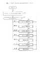
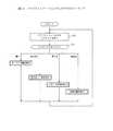
このプログラムは、コンフィギュレーションマネージャプロセス14aのGUIにより呼ばれ、GUIを介して、システムアドミニストレータからの入力情報に基づいて、グローバルマウントポイントテーブル14e(図2)、ペアテーブル30(図4)およびローカルマウントポイントテーブル(図3)を生成する。図13は、Config変更プログラムの動作の説明である。
ステップ101では、GUIからの入力は、その入力に基づいてグローバルマウントポイントテーブルでの変更を有効にするために受信される。つぎに、ステップ102では、各アプリケーションサーバ18について、サーバがコンテンツマネージャやアプリケーションサーバを含んでいるグローバルマウントポイントテーブルに基づいて、サーバに対して新しいローカルマウントポイントテーブルを生成する。各サーバについて、Config変更プログラムは、新しいローカルマウントポイントテーブルをシステム10のサーバ18に送る(ステップ103)。
ステップ104では、Config変更プログラムは、サーバの全てから完了メッセージが来るのを待つ。つぎに、ステップ105では、グローバルマウントポイントテーブルに基づいて新しいペアテーブルが生成される。ステップ106では、Config変更プログラムは、新しいペアテーブルを記憶システム22A(図1)へ送る。
Config変更プロセスは、ステップ107では、記憶システムからの完了メッセージを待ち、そしてそれを受け取ると、ステップ108で処理を完了させる。
更新ファイルチェックプログラム
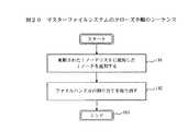
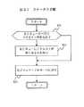
更新ファイルチェックプログラム14dは、最後のファイル更新が行われてから、どのファイルが更新されたかをチェックするために、コンフィギュレーションマネージャのGUIに呼び出される。図14は動作のシーケンスを示しており、コンテンツマネージャ16のマスターファイルシステムに対し、マウントポイントを付けてチェックメッセージを送るステップ120で始まる。マスターファイルシステムは、次に、更新ファイルチェックプログラムがステップ122で待っているマウントポイントのもとでの更新されたファイルのリストを返送する。リストが受け取られると(ステップ124)、リストはGUIのディスプレー(図示なし)に表示される。
コンテンツマネージャ
コンテンツマネージャ16は、基本的にはファイルを更新するためにサーバを動作させる。ファイルが生成、更新あるいは削除されると、ディレクトリーリスト、利用可能なブロックリスト、iノード情報、および利用可能なiノードリストを含むコンテンツマネージャにより維持されるメタデータも、変更される。
アプリケーションサーバ18により保持されているクライアントファイルシステムは、マスターファイルシステムと共にディレクトリーリストとiノード情報を共有する。共有のiノード情報はマスターファイルシステムによって変更されず、たとえリクエストがファイルの修正であっても、単に新しいiノードが生成されるだけである。また、すでにファイルにより使用されているブロック上のデータも変更されない。マスターファイルシステムは、マスターファイルシステムとクライアントファイルシステムとの間に不整合が生じないように、ディレクトリリストをアトミックに変更する。
マスターファイルシステム
コンテンツマネージャ16上で実行するマスターファイルシステムプロセスは、マスターボリューム34においてファイルを生成し、更新し、削除するように動作する。説明したように、各マスターボリュームは複数の複製されたボリューム36によりミラーされる。マスターボリュームの更新は、ディスクコントローラ24で実行中のリモートコピープロセス28により(上記で示したように時間ベースで)、アプリケーションサーバ18のクライアントファイルシステムで読み出して使用するために、複製されたボリューム36にコピーされる。それにより、マスターボリューム34上に保持されているデータと複製されたボリューム36に保持されているデータの間の整合性が維持される。
マスターファイルシステムプロセスを用いるアプリケーションは、7つのタイプのファイルレベルI/Oリクエストを作成する:すなわち、オープン、書き込み、読み出し、クローズ、削除、チェック、そして更新である。最後の2つのタイプはコンフィギュレーションマネージャによってのみ使用される。
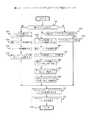
図15は、受け取った各種のI/Oリクエストを取り扱う際の、マスターファイルシステムの動作のステップを説明するものである。最初は(ステップ130)、プロセスはアプリケーションからのリクエストを待つ。リクエストを受け取ると、ステップ132ではタイプ(例えば、そのリクエストはファイルをオープンするのか、クローズするのか、書き込むのかなど)によりチェックされる。つぎに、リクエストのタイプが決まると、マスターファイルシステムプロセスは、リクエストのタイプに従い、7種類の手順133の一つを呼び出す。
オープン手順
オープン手順133aは、ファイルの使用を開始するときに、アプリケーションにより呼び出される。図16は用いられるステップを示す。考慮すべき三つのケースがある:すなわち、新しいファイルの生成(ケースa)と、現存のファイルへのデータ書き込みで、最後のファイル更新のあと初めてファイルが開かれる(ケースb)と、現存のファイルへのデータ書き込みで、最後のファイル更新のあとファイルが開かれるのは2回目かそれ以上(ケースc)。最初のケースと次の二つのケースとを区別するために、ファイルに対応したiノード情報(図6)の新しいファイルフラグが使用される。第2のケースと第3のケースを区別するためには、更新されたiノードリスト(図8)を参照する。更新されたiノードリストは、最後のファイル更新のあとで開かれたiノードを識別する。
第2のケースでは、マスターファイルシステムは、ファイルの現在のiノードを変更せず、むしろファイルに対する新しいiノードを生成する。第3のケースでは、マスターファイルシステムは、iノードはマスターファイルシステムのみが所有するという理由で、更新されたiノードリストのiノードのみを使用する。
図16を参照すると、ステップ142では、オープン手順は、チェックしてリクエストされたファイルが新しいかどうかを決める。そうであるなら、ステップ142aに進み、そうでないなら、ステップ142bに進む。ステップ142aは、ファイルに対して、利用可能なiノードのリスト(図10)から新しいiノード番号を割り当てることになる。つぎに、ステップ143aでは、手順は、利用可能なiノードリストから選択したiノード番号を使って、新しいiノードを生成し、利用可能なブロックリストにあるいくつかの利用可能なブロックを使用して、ボリューム上にiノード情報を記憶する。
つぎに、ステップ144aでは、オープン手順は、iノードの属性フィールドやそのiノード番号を初期化し、生成の日付を付け、その大きさやダイレクトエントリーのリストを識別する。ステップ145aでは、新しいファイルフラグはYesに設定される。これで、最後のファイル更新の後に生成されたものとしてファイルを識別する。手順は、以下に議論するステップ150と152に進む。もしリクエストされたファイルが新しくない場合は、手順はステップ142を離れてステップ142bに進み、リクエストされたファイルが更新されたiノードリストにあるかどうかをチェックする。もしそうであるなら、手順はステップ143cに進み、新しいiノード番号が、利用可能なiノードリストから、ファイルに割り当てられる。図17Aと図17Bは、ファイル(「ファイル3」オリジナルiノード番号は10)の修正と、新しいiノード番号(「11」)をファイル3に割り当てることと、ファイルを収容しているディレクトリ(「abc1/def/」)の修正の概略を説明している。
図16に戻り、もしリクエストされたファイルが更新されたiノードリストに無かったら、ステップ143bは新しいiノード番号を割り当てる。つぎに、ステップ144bでは、オープン手順は、新しいiノード番号で新しいiノードを生成する。つぎに、ステップ145bでは、オープン手順は、記憶システムのボリュームまたはキャッシュメモリーからファイルの現在のiノードを得る。つぎに、ステップ146bでは、手順は、現在のiノード情報の内容を新しいiノード情報にコピーする。これにステップ147bが続いて、そこで新しいファイルフラグが新しいiノードにおいて「No」に設定される。ステップ148bでは、各ディレクトリ(direct)エントリ−のフラグが、iノードの中で「No」に設定される。このエントリーは、ディレクトリエントリーで指定されたブロックはファイルの現在のiノードで使用されていることを知らせる。手順は、それ後ステップ150と152に進む。
ステップ150では、手順は、ファイルハンドルを開かれたiノードリストからファイルオープンへ割り当てる。ステップ152では、手順は、参考用として使用するためにファイルハンドルをアプリケーションへ戻し、ステップ154で終了する。
書き込み手順
書き込み手順133bは、ファイルにデータを書き込むために呼び出され、そうするためのステップは図18で説明される。考慮の必要がある三つのケースがある:すなわち、ファイルの終わりを越えてのデータ書き込みの場合(ケースa)、ファイルのオーバライトで、書き込まれるべきブロックが最後のファイル更新の後で割り当てられた場合(ケースb)、ファイルのオーバライトで、書き込まれるべきブロックがアプリケーションサーバ上のクライアントファイルシステムにより共有されている場合(ケースc)である。
ケースaでは、コンテンツマネージャ16上で動作しているマスターファイルシステム(図1)は、ファイルに新しいブロックを割り当てる。ケースbである第2のケースでは、マスターファイルシステムは、ファイルに新しいブロックを割り当てて、共有リソースへのデータ書き込みを防いでいる。ケースbでは、ブロックは、マスターファイルシステムだけが使用するので、ブロックはオーバライトされる。
図18を参照すると、書き込み手順はステップ160から始まり、リクエストで指定されたオフセットがファイルの終わりを越えているか否かを見るためのチェックをする。もし越えているなら、ステップ162aに進む。もし越えていないなら、手順はステップ162bに進む。一般には、オフセットはファイルの先頭からのアドレスである。
ステップ162aでは、書き込み手順は、利用可能なブロックリスト(図9)から新しいブロック番号を割り当てる。つぎに、ステップ163aでは、新しいディレクトリエントリーが、ファイルのiノードの終わりにブロック番号とともに追加される。また、ダイレクトエントリーのフラグが「Yes」に設定され、ステップ163aは終了する。下記で論議されるステップ170と172に進む。
一方、もし、ステップ160での判定が不成立である場合は、ステップ162bに進み、書き込まれるファイルのiノードからのアドレスに対応するダイレクトエントリーの選択を行う。つぎに、ステップ163bでは、ダイレクトエントリーについてフラグのチェックが行われる。もしそれが「Yes」であったら、ステップ164bに進み、もしそうでないなら、ステップ164cに進む。
ステップ164bでは、手順はダイレクトエントリーからブロック番号を得て、ステップ170、172に進む。
もしステップ164cがステップ162bに続くのであれば、手順は、リクエストされたファイルに割り当てるために、利用可能なブロックリスト(図9)から新しいブロック番号を選択する。図17Aと図17Bは、どのようにしてファイルが修正されるかも説明している。この図では、ディレクトリ「direct2」は、ファイルに追加される新しいデータ(「Mars」)を記憶するために、新しいロケーションA/A1/20を識別するように修正される(図17A参照)。
ステップ165cでは、iノードのダイレクトエントリーのブロック番号は、新しいブロック番号に変更され、次のステップ166cで、新しいダイレクトエントリーのフラグを「Yes」に設定する。
[95] ステップ170では、データは、ブロック番号で指定された場所に書き込まれ、ステップ172では、完了メッセージが、I/O書き込みリクエストが作成するアプリケーションに返される。つぎに、手順はステップ174で終了する。
読み出し手順
読み出し手順133cは、ファイルからデータを読み出すために呼び出されるもので、図19で説明される。ファイル上の読み出し動作は、共有リソースの変更を何も要求しない。このため、この手順は、ファイルのiノードに従い、リクエストで特定されたデータを単に読み出す。このようにして、図19が示すように、ステップ180は、ファイルのiノードからアプリケーションが特定したアドレスに対応するダイレクトエントリーを取り出す。
つぎに、ステップ183では、データが、ダイレクトエントリーのブロック番号で指定された場所から読み出される。つぎに、ステップ184では、データは要求しているアプリケーションに送られ、手順はステップ188で終了する。
クローズ手順
この手順は、ファイルの使用を完了させるために呼び出されるもので、図20で説明される。クローズ手順133dはステップ191から開始され、使用されたiノードとそのファイル名を更新されたiノードリストに追加する。これに続くステップ192では、前にアプリケーションによる使用のために割り当てたファイルハンドルの割り当て取り消しを行う。開かれたiノードリストのファイルハンドルのエントリーはYesに設定される。クローズ手順133dはステップ193で完了する。
削除手順
図21に示されるこの手順は、存在するファイルを削除するために呼び出される。削除手順133eがマスターファイルシステムにより呼び出されたときに、削除しようとしているファイルが、その時点で1ないしはそれ以上のアプリケーションサーバ18により使用されている可能性がある。ファイルを削除することは、マスターファイルシステム(コンテンツマネージャ16上で実行中)とクライアントファイルシステム(アプリケーションサーバ18上で実行中)とが共有しているいくつかのリソースを動作させることになる。したがって、マスターファイルシステムがこのような共有リソースを変更できる前に、アプリケーションサーバ18上で稼働中のアプリケーションがこのようなデータの削除を認識するように、マスターファイルシステムとクライアントファイルシステムとの間である種の同期化をしておく必要がある。
図21を参照すると、ステップ201と202は、ディレクトリリストからファイルのエントリーを消去し、ディレクトリリストを含むブロックをキャッシュメモリーから記憶システムへフラッシュすることを含んでいる。これは、エントリーのサイズが小さくて1セグメントに収まるので、同期化は無しに行うことが出来る。セグメントとは、ディスクドライブの読み書きするデータの単位である。したがって、この操作はアトミックである。
クライアントファイルシステムの挙動として三つのケースがある。もしクライアントファイルシステムがファイルを使用している場合は、ファイルに割り当てられたファイルのiノード情報とブロックはまだ消去されていないので、ファイルに対するI/Oを継続することが可能である。もしクライアントファイルシステムがファイルを使用していなくても、ファイルあるいはファイルのiノードを持つディレクトリリストが、クライアントファイルシステムのメモリーにキャッシュされている場合には、クライアントファイルシステムはまだファイルを読み出すことが出来る。もしクライアントファイルシステムがファイルを使用しておらず、ディレクトリリストとファイルのiノードをキャッシュしていない場合は、クライアントファイルシステムはファイルをそれ以上使用することは出来ない。
このようにして、ステップ203では、マスターファイルシステムは、修正されたエントリーを持つブロックが記憶システムの全てに到達するまで待つ。それを行うには、マスターファイルシステムは、ブロックが存在する特定のペアのステータスをチェックするために記憶システムのインターフェイスを使用する。このリクエストでペアの名称が特定される。
ステップ204では、無効メッセージが、各クライアントファイルシステムに、ファイルのiノード番号を付けて送られ、続いて、すべてのクライアントファイルシステムから完了メッセージが来るのを待つ(ステップ205)。予定した全ての完了メッセージを受信すると、マスターファイルシステムは、どのクライアントファイルシステムも消去するファイルを使っていないこと、どのクライアントファイルシステムもファイルのiノード情報を持っていないこと、およびクライアントファイルシステムのすべてがステップ201で修正された新しいディレクトリリストを読み出すことを確認する。
ステップ206では、マスターファイルシステムは、ファイルのために使われていた全てのブロックの割り当てを取り消す。つぎに、ステップ207では、ファイルのiノードが消去され、iノードに使用されていたブロックは割り当てを解除される。ステップ208では、完了メッセージがファイルの消去を要求していたアプリケーションに送られ、手順はステップ209で終了する。
チェック手順
図22に示される手順は、コンフィギュレーションマネージャプロセス14a(データセンタ12Aのマネージメントコンソール14上で実行;図1)が、更新されたiノードリストを得るために使用される。ステップ211で開始し、マウントポイントがコンフィギュレーションマネージャから取り出される。ステップ212では、マスターファイルシステムは、マウントポイントより下に記憶されていて、更新されたiノードリストにあるファイルのリストを、コンフィギュレーションマネージャに送る。手順は、ステップ213で終了する。
更新手順
この手順は、コンフィギュレーションマネージャが、更新されたiノードリストにあるファイルを更新するために使用され、図23に示されている。まず、ディレクトリリストが変更され、その結果アプリケーションサーバは更新されたファイルの新しいiノードを使用することが出来る。その後、全てのクライアントファイルシステムは、更新されたファイルのディレクトリリストとiノードに対応する、それらのキャッシュデータを無効にするように指示される。このステップ無しでは、クライアントファイルシステムが、更新されたファイルの、古くなったディレクトリリストとiノードを使い続ける可能性がある。最後に、マスターファイルシステムは、更新されたファイルの古くなったiノードに関連した情報の割り当てを取り消し、その情報を消去する。
図23を参照すると、ステップ221では、更新されたiノードリストにある新しいファイルに対して、対応するディレクトリリストにエントリーが追加される。更新されたiノードリストの更新されたファイルに関して、対応するディレクトリリストのエントリーのiノード番号が、新しいiノード番号に変更される。ステップ222では、修正されたディレクトリリストを持つブロックは、キャッシュメモリーから記憶システムへフラッシュされ、ステップ223では、ブロックが全ての記憶システムに届くことが出来るように、待ちが挿入される。つぎに、ステップ224では、無効メッセージが、各クライアントファイルシステムに、更新されたファイルのiノード番号をつけて送られる。ステップ225では、手順は、全てのクライアントファイルシステムから完了メッセージが来るのを待つ。
ステップ226では、更新されたファイルの古いiノードでのみ使用されていたブロックの全ての割り当てを取り消す。ステップ227では、古いiノードは削除され、古いiノードによって使用されていた全てのブロックは、割り当てが取り消される。つぎに、ステップ228では、更新されたiノードリストは消去され、手順はステップ229で終了する。
マウントクライアント
コンテンツマネージャ16のマウントクライアントプロセスは、ローカルマウントポイントテーブルに従って、特定のディレクトリに新しいボリュームをマウントする機能を持つ。このテーブルは、各サーバに記憶されるので、サーバがリブートする時には、マウントクライアントは、ボリュームをマウントするためにローカルマウントポイントテーブルを使用する。リブート後、コンフィギュレーションマネージャはシステムの構成を変更する。
この場合、コンフィギュレーションマネージャ上のマウントポイント更新プログラムは、各サーバに対しローカルマウントポイントテーブルを作成し、それをサーバに送る。したがって、マウントクライアントは、新しいローカルlマウントポイントテーブルに従って、ボリュームをマウントし、アンマウントする。図24はマウントクライアントプロセスのシーケンスを示しており、マネージメントコンソール14で実行するコンフィギュレーションマネージャ14aから、新しいローカルマウントポイントテーブルが来るのを待つ、ステップ231で始まる。
つぎに、テーブルの各マウントポイントについて、ボリュームは指定されたディレクトリにマウントされる(ステップ232)。ステップ233では、サーバ上のマウントした各ボリュームについて、もしローカルマウントポイントテーブルにボリュームに対するエントリーがない場合は、ボリュームはアンマウントされ、ステップ234では、完了メッセージがマウントポイントアップデートプログラムに送られ、そして手順はステップ231に戻り、新しい変更を待つ。
アプリケーションサーバ
アプリケーションサーバ18は、例えばビデオサーバなどの、アプリケーションを実行するサーバである。アプリケーションは、記憶システム22に記憶されているファイルを、クライアントファイルシステムを通して使用する。本発明では、アプリケーションはファイルを修正することなく、単に読み出すだけ、としている。
クライアントファイルシステム
クライアントファイルは、記憶システム22からファイルを探し出し、読み出すために用いられる、サーバ18で実行するプロセスであり、マスターファイルシステムと交信する必要はない。したがって、クライアントファイルシステムプロセスは、アプリケーションに対して、ファイルを開く、ファイルを読み出す、ファイルを閉じる、およびキャッシュデータを無効にするためのインターフェイスを提供する。無効化のインターフェイスはマスターファイルシステムだけが使用する。図25は、クライアントファイルシステムプロセスが、クライアントファイルシステムのサーバ18上で稼働するアプリケーションからのリクエストを引き受けるのに行うステップを示している。
図25が示すように、クライアントファイルシステムは、ステップ241において、アプリケーションからのリクエストを待つ。リクエストを受け取ると、プロセスは、ステップ242で、リクエストのタイプに応じて、手順(オープン、読み出す、クローズ、または無効)の一つを呼び出す。
オープン手順
アプリケーションがファイルを使い始めるときには、オープン手順が呼び出される。図26は、ステップ251で始まるオープン動作のステップを示している。このステップでは、開くファイルのiノード番号をディレクトリリストから取り出す。つぎに、ステップ252では、iノード番号に対応するiノード情報が、記憶システムあるいはキャッシュメモリーから読み出される。ステップ253では、ファイルハンドルが、開かれたiノードリストから、このファイルオープンのために割り当てられ、ステップ256でアプリケーションへ返される。ステップ257で手順は終了する。
読み出し手順
この読み出し手順は、ファイルの読み出しであり、そのステップは、基本的には、図19に示すマスターファイルシステムの読み出し動作により行われる、読み出し動作に用いられるものと同じである。
クローズ手順
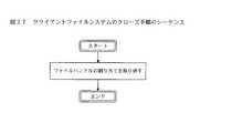
この手順は、アプリケーションがファイルの使用を終了するときに呼び出される。図27は、ファイルハンドルの割り当て取り消しだけを含む、手順の主なステップを示している。
無効手順
この手順は、マスターサーバにより更新されたキャッシュデータを無効にするために、コンテンツマネージャ16(図1)のマスターファイルシステムにより呼び出される。無効にした後は、クライアントファイルシステムは、ファイルシステムを実行しているアプリケーションが必要とする場合は、更新されたディレクトリリスト、新しいiノードなどを読み出す。図28に使用されるステップを示す。最初に、手順は、リクエストにより指定されたiノードをどのアプリケーションも使わなくなるまで待つ(ステップ261)。つぎに、ステップ262では、手順は、中にiノードのエントリーがあるディレクトリリストとiノード自身とファイルに割り当てられたブロックを含む、キャッシュされたデータを無効にし、ステップ263では、完了メッセージをマスターファイルシステムに送り、ステップ264で完了する。
マウントクライアント
マウントクライアントは、ローカルマウントポイントテーブルに従って、特定のディレクトリに新しいボリュームをマウントする。マウントクライアントプロセスで用いられるステップは、基本的にはマスターファイルシステムで用いられるものと同じであり、したがって図24で示されている。
記憶システム
記憶システム22は、論理記憶装置の技術を用いており、したがって、図1に示すように、マスターボリューム34や複製されたボリューム36を含む複数のボリュームで構成される。各記憶システムは、少なくとも1台のディスクコントローラ24と、ディスクコントローラとボリュームの間のI/Oパスを含んでいる。マスターボリュームは、オリジナルファイルを保有するボリュームであり、マスターファイルシステムにより管理される。複製されたボリュームは、それぞれがマスターボリュームの複製であり、アプリケーションサーバにより使用される。
ディスクコントローラでは、ブロックI/Oプロセスとリモートコピープロセスの二つの処理が実行されている。ブロックI/Oプロセスは、サーバからのI/Oリクエストを処理する仕事をする。リモートコピープロセスは、マスターボリュームからデータを少なくとも1個の複製されたボリュームにコピーする仕事をする。マスターボリュームと複製されたボリュームは、同じ記憶システムにあること、あるいは異なった記憶システムにある事が出来る。同じ記憶システムの場合は、データは内部のI/Oパス経由でコピーされる。異なった記憶システムの場合には、データは記憶システム間のWANネットワークを経由してコピーされる。ペアテーブルは、どのボリュームがどのボリュームに複製されたのかを示す。
ブロックI/Oプロセス
図29は、ブロックI/Oプロセス26のステップを示す。ステップ271では、ブロックI/OプロセスはサーバからのI/Oリクエストを待つ。
リクエストを受け取ると、プロセスはステップ272でタイプをチェックする。リクエストには、データ読み出しとデータ書き込みの、二つのタイプがある。もしリクエストが読み出しであれば、ステップ273は読み出し手順を呼び出し、もしそれが書き込みリクエストであれば、書き込み手順が呼び出される。手順は、次にステップ271に戻り、次のリクエストを待つ。
図30は読み出し手順を示す。まず、手順は、ブロックI/Oプロセスがデータを読み出す場所を得る(ステップ281)。サーバからのI/Oリクエストはこのような種類の情報を含んでいる。例えば、SCSIプロトコルの読み出しコマンドは、SCSIターゲットID、LUN、オフセットおよびデータのサイズを含んでいる。この場合、場所は、SCSIターゲットID、LUN、オフセットおよびサイズによって指定される。手順は、次にその場所からデータを読み出し(ステップ282)、それをサーバに完了メッセージを付けて送る(ステップ283)。
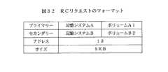
図31は、ブロックI/Oプロセスによって呼び出される書き込み手順の図である。ステップ291から始まり、プロセスは送られたデータが書き込まれる場所を知る。次に、データをその場所に書き込み(ステップ292)、続いてステップ293で、完了メッセージを返す。次に、その位置がペアテーブル(図4)のいずれかのボリュームに関係づけらるかを判定するために、ステップ294でチェックが行われる。もし関係づけ出来ない場合は、手順はステップ298で終了する。しかし、もし関係づけ出来る場合は、どのペアにその位置が属するかを識別するために、手順はステップ295へ進む。ステップ296では、このI/Oに対するリモートコピー(RC)リクエストが生成される。図32はRCリクエストの構造の例である。
図32が示すように、RCリクエストは、4つの行、すなわちプライマリー、セカンダリー、アドレス、およびサイズを持っている。プライマリーは、ペアのプライマリーボリューム情報を識別する。セカンダリーは、ペアのセカンダリーボリューム情報である。アドレスは、データが書き込まれたアドレスである。サイズは、書き込まれれたデータのサイズである。
図31に戻り、ステップ297では、手順は、RCリクエストのリストであるRCキューにRCリクエストを挿入する。リモートコピープロセスは、このRCキューを使って、どのデータをどの位置にコピーする必要があるのかを知る。図33は、多数のRCリクエストを示しているRCキューの例を示す。
リモートコピープロセス
リモートコピープロセスは図34で示されており、プライマリー記憶システムから来るデータがあるかどうかを確定するためのステップ301から始まる。もしデータがあるなら、受信手順を呼び出すためにステップ301aに進む。もしデータがないなら、プロセスはステップ302に行く。これは、セカンダリー記憶システムで実行しているリモートコピープロセスがプライマリー記憶システムから更新されたデータを受け取るケースである。
ステップ302では、RCキューに保留されているRCリクエストがあるかどうかを判定する。もしあるなら、ステップ302aで送信手順を呼び出す。もしないなら、ステップ303に進む。これは、プライマリー記憶システムで実行しているリモートコピープロセスがセカンダリー記憶システムに更新されたデータを送るケースである。
ステップ303では、RCキューがペアテーブルの構成を変えるリクエストを持っているかどうかを知るためにチェックする。もし持っているなら、ステップ303aでリクエストに従ってテーブルを変更する。もし持っていなければ、ステップ304に進む。これは、コンフィギュレーションマネージャがリクエストを送り、リモートコピープロセスがテーブルを再構成するケースである。
ステップ304では、ペアのステータスチェックのリクエストがあるか、RCキューのチェックが行われる。もしあるなら、ステップ304aはステータス手順を呼びだし、もしないなら、ステップ301へ戻る。これは、マスターファイルシステムが、更新されたデータの全てがセカンダリー記憶システムの全てに届いているかを知ることを希望するケースである。
RCプロセスのステップ302aで呼び出される送信手順は、図35で示される。ステップ311では、手順は、RCリクエストをRCキューから取り出し、プライマリーボリュームからリクエストにより特定された位置からリクエストされた対応するデータを読み出し(ステップ312)、そのデータをセカンダリーボリュームの識別子と位置とともに指定された記憶システムに送る(ステップ313)。
図36は受信手順を示す。呼び出されると、ステップ321で、読み出し手順は、セカンダリーボリュームの識別子と受信したデータを書き込むアドレスとを得る。つぎに、ステップ322では、データをその位置に書き込む。最後に、ステップ323では、完了メッセージがプライマリー記憶システムに送られる。
図37は、リモートコピープロセスのステップ304aで呼び出されるステータス手順を示す。呼び出されると、手順は、ステップ331で、RCキューにおいて特定のペアに対するRCリクエストがあるかどうかを知るためにチェックを行う。もしこのようなリクエストが存在するならば、手順は、ステップ332で、そのペアに対する全てのリクエストが完了するまで待ち、次に、ステップ333では、サーバに完了メッセージを返す。もし、ステップ331で、RCキューに特定のペアに対するRCリクエストが無いと判断された場合は、手順は単に完了メッセージをサーバに送る。
結論
要約すると、サーバがデータを共有し、単にデータを読み出したりする、多くのクラスターサーバおよび分散されたクラスターサーバの間でデータを分散および共有するための装置と方法が開示された。このようなサーバの例は、WEBサーバ、ビデオサーバおよびコンテンツディストリビューションサーバである。
【発明の効果】
プライマリーデータセンタの記憶システムはファイルを自分から他のデータセンタの記憶システムにブロックレベル転送を用いてコピーするので、ファイルシステムの助けを必要としない。これにより、CPU負荷またはサーバのI/Oバンド幅は無駄にされないので、データ転送速度を制約せず、また高めることが出来る。
【図面の簡単な説明】
【図1】本発明を利用するために構成された、プライマリー記憶システムと複数のセカンダリー記憶システムを含む、代表的なデータプロセッシングシステムのブロックダイアグラムである。
【図2】プライマリー記憶システムとセカンダリー記憶システム上のファイルの位置を識別するために、図1のデータプロセッシングシステムのコンテンツマネージャにより管理されるデータ構造の一部を形成する、グローバルマウントポイントテーブルの説明である。
【図3】それぞれのペアがプライマリー記憶システムの記憶エリアであり、1ないしはそれ以上のセカンダリー記憶システムの記憶エリアである、記憶エリアのペアを識別するのに用いられるペアテーブルの説明である。
【図4】セカンダリー記憶システムに使用されるであろうローカルマウントポイントテーブルの説明である。
【図5】どのファイルがディレクトリーにあるかを識別する情報を持っている、特定のディレクトリに対するディレクトリリストの説明である。
【図6】ファイルに関連する特定のファイルと属性の場所を識別する、iノードリストの例である。
【図7A】図5のディレクトリリストと図6のiノードリストとの間の関係の図による説明である。
【図7B】図5のディレクトリリストと図6のiノードリストとの間の関係の図による説明である。
【図8】更新されたiノードリストの説明である。
【図9】利用可能なブロックリストを示す。
【図10】利用可能なiノードリストを示す。
【図11】開かれたiノードリストを示す。
【図12】ファイル更新シーケンスを説明するフロー図である。
【図13】システム構成を変更するためのステップのフロー図である。
【図14】ファイル更新チェックの主要なステップを説明するフロー図である。
【図15】ファイルオペレーション手順を呼び出すための、マスターファイルシステムでの主要なステップを示す。
【図16】マスターファイルシステムにより呼び出された、オープン手順を説明するフロー図である。
【図17A】オープン手順でファイルを修正する際に使用される、利用可能なiノードリストから新しいiノードを選択する事についての説明である。
【図17B】オープン手順でファイルを修正する際に使用される、利用可能なiノードリストから新しいiノードを選択する事についての説明である。
【図18】マスターファイルシステムにより呼び出された、書き込み手順を説明するフロー図である。
【図19】マスターファイルシステムにより呼び出された、読み出し手順を説明するフロー図である。
【図20】マスターファイルシステムにより呼び出された、クローズ手順を説明するフロー図である。
【図21】マスターファイルシステムにより呼び出された、削除手順を説明するフロー図である。
【図22】マスターファイルシステムにより呼び出された、チェック手順を説明するフロー図である。
【図23】iノードリストを更新するために、マスターファイルシステムにより呼び出された、更新手順を説明するフロー図である。
【図24】特定のディレクトリに新しいボリュームをマウントするために、マウントクライアントプロセスによりとられるシーケンスを説明する。
【図25】ファイルシステム手順を呼び出すためにクライアントファイルシステムプロセスにより取られるシーケンスステップを示す。
【図26】クライアントファイルシステムプロセスのオープン手順に対する呼び出しにより取られるステップを説明する。
【図27】クライアントファイルシステムプロセスのクローズ手順に対する呼び出しにより取られるステップを説明する。
【図28】クライアントファイルシステムプロセスの無効化手順に対する呼び出しにより取られるステップを説明する。
【図29】図1の記憶システムにより実行されるブロックI/Oプロセスの処理手順のステップを示す。
【図30】図29のブロックI/Oプロセスにより呼び出される際の、読み出し手順の動作を説明する。
【図31】図29のブロックI/Oプロセスにより呼び出される際の、書き込み手順の動作を説明する。
【図32】書き込み手順によりなされるであろうリモートコピー(RC)リクエストの説明である。
【図33】図1の記憶システムにより用いられる可能性のあるリモートコピーキューの例である。
【図34】リモートコピープロセスにしたがって、図1の記憶システムにより取られるステップを説明する。
【図35】図34のリモートコピープロセスにより呼び出される送信手順のステップを示す。
【図36】図34のリモートコピープロセスにより呼び出される受信手順のステップを示す。
【図37】図34のリモートコピープロセスにより呼び出されるステータス手順のステップを示す。
【符号の説明】
14・・・マネージメントコンソール、14a・・・コンフィギュレーションマネージャ、14b・・・ファイル更新プロセス、14c・・・コンフィグ変更プロセス、14d・・・更新ファイルチェックプログラム、14e・・・グローバルマウントポイントテーブル、16・・・コンテンツマネージャ、16a・・・アプリケーション、16b・・・マスターファイルシステム、16c・・・マウントクライアント、16d・・・メタデータ、16e・・・ローカルマウントポイントテーブル、16f・・・更新されたiノードリスト、18b・・・クライアントファイルシステム、18c・・・マウントクライアント、18d・・・メタデータ、18e・・・ローカルマウントポイントテーブル、22A…記憶システムA、24・・・ディスクコントローラ、26・・・ブロックI/Oプロセス、28・・・リモートコピープロセス、30・・・ペアテーブル、34・・・マスターボリューム、36・・・複製されたボリュームTECHNICAL FIELD OF THE INVENTION
The present invention relates generally to data processing systems, and more particularly to a storage system capable of transferring block-level I / O data from a primary storage system to several secondary storage systems. Data location information in the form of a file system is separately transferred to a user of the secondary storage system.
[Prior art]
With the availability of large storage systems such as these days and easy access to such storage systems via the Internet, for example, watching videos in real time for both entertainment and education The request for the application comes out. For example, the use of the Internet as a communication medium allows video files to be transferred virtually anywhere in the world. However, as many users have access to larger storage systems, there are associated problems. It is a performance degradation that occurs as a result of a bottleneck, which occurs naturally when at least many users try to access the same file at about the same time.
One solution is to set up multiple data centers in different locations to distribute the access load from users. This allows multiple users to access (video) files at one location in many locations. A primary location, such as a movie studio in a video file (movie), can distribute the file to all data centers.
However, video files are usually managed in the operating system's file system. Applications running on the operating system, such as video servers, treat the video as a file for convenience of access. Generally, video file transfer involves file-level I / O, such as "File Transfer Protocol" (FTP), to copy a file from one server to another via a TCP / IP network. Use / O. This protocol assumes that the data is stored on a file system.
However, file-based data transfer methods have the drawback of low data transfer rates, often due to the large overhead of the file system. As a file system, a logical file management system is often used in which a logical "volume" maps to a predetermined portion of storage space, usually by a number of disk devices. For reading and / or writing files, the file system also includes the file's metadata, information describing the file, which often identifies where the file is stored on the volume, and the file name, size, Read and write related attributes such as last access time. Because the metadata is also stored on the volume, metadata operations involving read and / or write operations on the file reduce CPU power and I / O bandwidth. This is why the transfer speed based on file transfer is low.
There are services that can provide a file distribution service. Akamai and Digital Island are some examples of such services, and are subject to the problems described earlier because they typically use file-based data transfer methods as described above. There are also remote copy methods that provide block-level data transfer. This transfer method is described in U.S. Pat. No. 5,742,792. However, the transfer method used is not configured to be used for applications that use the file system. This means that even if the data is copied, the application or file system cannot process the transferred data.
[Problems to be solved by the invention]
The present invention is directed to a processing system having multiple copies of data distributed from a primary or master storage system to a number of secondary storage systems. The present invention enables an application running on a server to make file-level I / O access to a storage system while allowing block-level I / O to be used for data transfer between storage systems. Provides systems and methods.
[Means for Solving the Problems]
In the present invention, the processing system includes two or more data centers. The primary data center has a management console, at least one content manager, a storage system for storing original data, and may also have an application server. Other data centers include application servers and storage systems. In the primary data center, the management console, the content manager, and the application server, if any, are interconnectedly connected to one another on a first network and to a second network for an associated storage system. Connected. The original data held in the storage system at the primary data center is mirrored to the remaining (secondary) storage systems at other data centers.
The storage system of the primary data center and the storage system of another data center are connected via a third network. The management console and the content manager are coupled to the primary storage system for data access thereto, and the application server connects to one or another of the secondary storage systems for access. Application processes running in the data center make file-level I / O requests, while accessing storage media controlled by the storage system uses block-level I / O.
In response to user input through the management console (eg, a system administrator), the content manager operates to configure the system. The content manager also generates a data structure that identifies the location of the data of the file on the primary storage system and stores the data.
Changes to the data (deletions, changes, etc.) are reflected by changes to the data structure to identify changed files and changed locations on the storage medium. The data structure corresponding to the changed data is also made available on the secondary storage system through a data communication on the second network, by a remote copy process executed on the primary storage system. The data structure of the content manager and the application server are synchronized so that the application server can know changes to the data (mirrored) held by the secondary storage system.
BEST MODE FOR CARRYING OUT THE INVENTION
According to the present invention, a primary or master data center includes a primary processing mechanism and a storage system in which a master copy of the data is maintained. The data stores a data structure (a directory list, an inode list, etc.) for identifying the location of the data. Data is periodically changed (deleted, modified, etc.). The changes are written to a previously unused area of the storage medium containing the data. When the data has been changed, the data structure is modified to identify the location of the changed data. Next, the changed data and data structure are placed on the remote copy queue. The remote copy process periodically scans the remote copy queue to see the changes made since the last scan, and if changed data is found, the changed data is Along with the structure, it is copied to one or more secondary storage systems and made available to an application server coupled to the secondary storage system.
The primary processing mechanism sends a message to the application server upon confirming that the changed data and the associated modified data structure have been received by the secondary storage system. When the application server receives the message, it signals that the data has changed. The application server retrieves the modified data structure from the associated storage device so that the updated data is used instead of the old (unmodified) data.
System configuration
Turning to the figures, FIG. 1 is an illustration of a basic data processing system, designated by the
The
The
Logical storage is implemented by the
Note that as shown in FIG. 1, the
Next, the various file structures used by the file system to locate the data are modified, and the modified file structures are also written to the storage device. The resulting data image or file structure changes are later copied from the
As further shown in FIG. 1, the management console executes or is capable of executing a configuration manager process 14a, a file update process 14b, a configuration change process 14c, and an update file check program 14d. These processes, as can be seen, perform the other functions described below for configuring and modifying the file structure for file-level I / O access, as well as the global mount point table. 14e is managed and held.
The content manager executes an application process, a master file system, a mount client that operates to hold metadata describing each file storage device on
The particular system architecture is representative, and it will be apparent to one skilled in the art that other system designs can be used. For example, an application may execute on an application server that operates through a file server to access data held by storage system 22. If so, the application server does not need to install a client file system because the application server is executed on the file server to read the file on the storage system.
table
As described above, the
Global mount point table
The global mount point table 14e is held by the
Some sets of files may be copied to a particular data center, other sets of files may be copied to other data centers, and so on. This is why there are many configurations. Each configuration identifies a different data set that is different from each other.
Local mount point table
FIG. 3 shows a local mount point table, one of which is in the content manager 16 and in each application server 16 of the system. The local mount point table contains information about which volume the unit (content manager or server) mounts. As shown in FIG. 3, the server B1 mounts the volume designated by the storage system B and the volume B1 on the directory / mnt1. The local mount point table is generated and distributed by the configuration manager process 14a.
Pair table
The pair table 30 is managed by the
The primary volume is a volume containing the original file, and is managed by the master file system process of the content manager 16. The secondary volume mirrors the primary volume and holds a copy of the data on the primary volume. The secondary volume is used by the application server.
Directory listing
The directory list is a table, one for each directory in the file system. The directory list contains information identifying each file in the directory along with each inode number of the file. FIG. 5 is an example of a directory list, in which the directory abc is
Inode information
As is common in file-level systems, an inode is present for each file in the file system, not only the attributes associated with the file, but also information for locating the file on the corresponding
Directory entries (eg, Direct1, Direct2, etc.) identify the locations of various volume data that form files on the storage system. Each directory entry has a "new" flag associated with it that indicates whether the location is used by the file's current inode. Details regarding this flag will be described below.
For example, as described above, the file having the
FIGS. 7A and 7B illustrate the relationship between a file, a directory list, and inode information when storing a file in a volume.
FIG. 7A illustrates a file containing text, although the file could easily be a video file or other file. FIG. 7B shows that a file having a file name of “
Updated inode list
The updated inode list is a table including information on which file has been updated or generated since the last file update. The inode associated with the updated file is also included in this table. FIG. 8 is an example of an updated inode list. The file name column identifies the file, and the "new inode number" identifies the inode assigned to the (updated) file.
Available block list
The available block list is a table including information on which location of each
Available inode list
Like the available block list, the available inode list is a table that identifies which inode numbers are used and which are available. FIG. 10 is an example of a list. If the availability flag of the i-node number is Yes, the i-node number is available. If it is No, the inode number has been used to identify the file.
Open inode list
The open inode list is a table that contains information about which files are currently used (ie, open) by the application. FIG. 11 is an example of such a list. The list contains the file descriptor as an identifier of the opened file.
As with some file systems, when an application opens a file, the file system assigns a file descriptor to the file open. Thereafter, the application uses this file descriptor while the file is open. In this example, file
Management console
The management console is, for example, a processor unit that provides a graphic user interface (GUI) to a system administrator that configures the system and provides file updates on time. Even if the file is updated by the content manager, its contents will not be visible to the application server without telling the timing from the management console.
GUI
The
Further, the GUI can provide the system administrator with a means for updating the file with the specified time. The administrator can specify the configuration name, and can instruct the content manager on the timing by pressing the OK button. A GUI screen (not shown) can provide a list of updated files to easily understand which files have been updated for the specified configuration. When called by the GUI, the update file check program 14d (FIG. 1) provides this list.
File update process
As indicated above, this process is called by the GUI of the configuration manager process 14a. The file update process (14b) contacts the content manager 16 to request identification of the updated file to be sent to the
Config change program
This program is called by the GUI of the configuration manager process 14a, and through the GUI, based on input information from the system administrator, the global mount point table 14e (FIG. 2), the pair table 30 (FIG. 4), and the local mount Generate a point table (FIG. 3). FIG. 13 illustrates the operation of the Config change program.
At
In
The Config change process waits for a completion message from the storage system at
Update file check program
The update file check program 14d is called by the GUI of the configuration manager to check which file has been updated since the last file update. FIG. 14 shows a sequence of the operation, and starts at
Content Manager
The content manager 16 basically operates a server to update a file. As files are created, updated, or deleted, the metadata maintained by the content manager including the directory list, available block list, inode information, and available inode list also changes.
The client file system held by the
Master file system
A master file system process running on the content manager 16 operates to create, update, and delete files on the
Applications that use the master file system process make seven types of file-level I / O requests: open, write, read, close, delete, check, and update. The last two types are used only by the configuration manager.
FIG. 15 illustrates steps of the operation of the master file system when handling various received I / O requests. Initially (step 130), the process waits for a request from the application. Upon receiving the request, step 132 checks by type (eg, whether the request opens, closes, or writes a file). Next, when the type of request is determined, the master file system process calls one of seven types of procedures 133 according to the type of request.
Open procedure
The open procedure 133a is called by the application when starting to use a file. FIG. 16 shows the steps used. There are three cases to consider: creating a new file (case a), writing data to an existing file, and opening the file for the first time after the last file update (case b), When writing data to the file, the file is opened for the second time or more after the last file update (case c). In order to distinguish between the first case and the next two cases, a new file flag of the inode information (FIG. 6) corresponding to the file is used. To distinguish the second case from the third case, refer to the updated inode list (FIG. 8). The updated inode list identifies inodes that have been opened since the last file update.
In the second case, the master file system does not change the file's current inode, but rather creates a new inode for the file. In the third case, the master file system uses only the inodes in the updated inode list, because the inode is owned only by the master file system.
Referring to FIG. 16, at
Next, in
Referring back to FIG. 16, if the requested file is not in the updated inode list, step 143b assigns a new inode number. Next, in
In step 150, the procedure assigns a file handle from the opened inode list to a file open. At
Writing procedure
Write procedure 133b is called to write data to the file, and the steps to do so are described in FIG. There are three cases that need to be considered: when writing data beyond the end of the file (case a), in a file overwrite, the block to be written was allocated after the last file update Case (case b) is a case where a block to be written is shared by a client file system on an application server due to overwriting of a file (case c).
In case a, the master file system (FIG. 1) running on the content manager 16 allocates a new block to the file. In the second case, case b, the master file system allocates new blocks to the file to prevent writing data to shared resources. In case b, the block is overwritten because it is used only by the master file system.
Referring to FIG. 18, the write procedure begins at
In
On the other hand, if the determination in
In step 164b, the procedure obtains the block number from the direct entry, and proceeds to
If step 164c follows step 162b, the procedure selects a new block number from the available block list (FIG. 9) to assign to the requested file. FIGS. 17A and 17B also illustrate how the file is modified. In this figure, directory "direct2" is modified to identify a new location A /
In step 165c, the block number of the direct entry of the inode is changed to a new block number, and in the
[95] At step 170, the data is written to the location specified by the block number, and at
Readout procedure
The read procedure 133c is called to read data from a file, and is described in FIG. A read operation on a file does not require any modification of the shared resource. Thus, this procedure simply reads the data specified in the request according to the inode of the file. Thus, as shown in FIG. 19,
Next, in
Closing procedure
This procedure is called to complete the use of the file and is described in FIG. The close procedure 133d starts at
Removal procedure
This procedure, shown in FIG. 21, is called to delete an existing file. When the
Referring to FIG. 21,
There are three cases of client file system behavior. If the client file system is using the file, I / O to the file can be continued because the inode information and blocks of the file assigned to the file have not been erased yet. Even if the client file system is not using the file, the client file system may still be able to read the file if the file or directory listing with the file's inode is cached in the client file system's memory. I can do it. If the client file system is not using the file and has not cached the directory list and the file's inode, the client file system cannot use the file anymore.
Thus, in
In
In
Check procedure
The procedure shown in FIG. 22 is used by the configuration manager process 14a (executed on the
Update procedure
This procedure is used by the configuration manager to update the files in the updated inode list and is shown in FIG. First, the directory listing is changed, so that the application server can use the new inode for the updated file. Thereafter, all client file systems are instructed to invalidate their cached data corresponding to the updated file directory listing and inode. Without this step, the client file system could continue to use outdated directory listings and inodes for updated files. Finally, the master file system deallocates the information associated with the stale inode of the updated file and erases the information.
Referring to FIG. 23, in step 221, for a new file in the updated inode list, an entry is added to the corresponding directory list. For the updated file in the updated inode list, the inode number of the corresponding directory list entry is changed to the new inode number. In
In
Mount client
The mount client process of the content manager 16 has a function of mounting a new volume on a specific directory according to the local mount point table. This table is stored on each server, so when the server reboots, the mount client uses the local mount point table to mount volumes. After the reboot, the configuration manager changes the configuration of the system.
In this case, the mount point update program on the configuration manager creates a local mount point table for each server and sends it to the server. Therefore, the mount client mounts and unmounts the volume according to the new local l mount point table. FIG. 24 shows the sequence of the mount client process, starting at
Next, for each mount point in the table, the volume is mounted on the specified directory (step 232). In
Application server
The
Client file system
A client file is a process executed on the
As shown in FIG. 25, in step 241, the client file system waits for a request from an application. Upon receiving the request, the process calls one of the procedures (open, read, close, or invalid), depending on the type of request, at
Open procedure
When an application starts using a file, the open procedure is called. FIG. 26 shows the steps of the open operation starting at
Readout procedure
This reading procedure is a file reading, and the steps are basically the same as those used for the reading operation performed by the reading operation of the master file system shown in FIG.
Closing procedure
This procedure is called when the application finishes using the file. FIG. 27 shows the main steps of the procedure, including only the deallocation of the file handle.
Invalidation procedure
This procedure is called by the master file system of the content manager 16 (FIG. 1) to invalidate cache data updated by the master server. After disabling, the client file system reads updated directory listings, new inodes, etc., if required by the application running the file system. FIG. 28 illustrates the steps used. First, the procedure waits until no application uses the inode specified by the request (step 261). Next, in
Mount client
The mount client mounts a new volume on a specific directory according to the local mount point table. The steps used in the mount client process are basically the same as those used in the master file system, and are therefore shown in FIG.
Storage system
The storage system 22 uses the technology of a logical storage device, and is therefore composed of a plurality of volumes including a
In the disk controller, two processes of a block I / O process and a remote copy process are executed. The block I / O process is responsible for handling I / O requests from the server. The remote copy process serves to copy data from the master volume to at least one replicated volume. The master volume and the replicated volume can be on the same storage system or on different storage systems. For the same storage system, data is copied via an internal I / O path. In the case of different storage systems, data is copied over the WAN network between the storage systems. The pair table indicates which volume has been copied to which volume.
Block I / O process
FIG. 29 shows the steps of the block I / O process 26. In
Upon receiving the request, the process checks the type at
FIG. 30 shows the reading procedure. First, the procedure obtains a location from which the block I / O process reads data (step 281). The I / O request from the server contains such kind of information. For example, a read command of the SCSI protocol includes a SCSI target ID, LUN, offset, and data size. In this case, the location is specified by the SCSI target ID, LUN, offset and size. The procedure then reads the data from the location (step 282) and sends it to the server with a completion message (step 283).
FIG. 31 is a diagram of the write procedure called by the block I / O process. Beginning at
As shown in FIG. 32, the RC request has four lines: primary, secondary, address, and size. The primary identifies the primary volume information of the pair. Secondary is the secondary volume information of the pair. The address is the address where the data was written. The size is the size of the written data.
Referring back to FIG. 31, in
Remote copy process
The remote copy process is shown in FIG. 34 and begins with
In
In
In step 304, the RC queue is checked for a request for a status check of the pair. If so,
The transmission procedure called in
FIG. 36 shows the receiving procedure. When called, in
FIG. 37 shows the status procedure called in
Conclusion
In summary, an apparatus and method for distributing and sharing data among a number of clustered servers and distributed clustered servers, where the servers share data and simply read data, has been disclosed. Examples of such a server are a web server, a video server and a content distribution server.
【The invention's effect】
The storage system of the primary data center copies files from itself to the storage systems of other data centers using block-level transfer and does not require the help of a file system. As a result, the CPU load or the I / O bandwidth of the server is not wasted, so that the data transfer speed can be restricted and increased.
[Brief description of the drawings]
FIG. 1 is a block diagram of an exemplary data processing system including a primary storage system and a plurality of secondary storage systems configured to utilize the present invention.
FIG. 2 is a description of a global mount point table that forms part of a data structure managed by a content manager of the data processing system of FIG. 1 to identify locations of files on a primary storage system and a secondary storage system. It is.
FIG. 3 is an illustration of a pair table used to identify pairs of storage areas, each pair being a storage area of a primary storage system and one or more secondary storage systems.
FIG. 4 is an illustration of a local mount point table that may be used for a secondary storage system.
FIG. 5 is an illustration of a directory listing for a particular directory having information identifying which files are in the directory.
FIG. 6 is an example of an inode list identifying specific file and attribute locations associated with a file.
7A is a diagrammatic description of the relationship between the directory list of FIG. 5 and the inode list of FIG. 6;
7B is a graphical description of the relationship between the directory list of FIG. 5 and the inode list of FIG. 6;
FIG. 8 is an explanation of an updated inode list.
FIG. 9 shows an available block list.
FIG. 10 shows a list of available inodes.
FIG. 11 shows an opened inode list.
FIG. 12 is a flowchart illustrating a file update sequence.
FIG. 13 is a flowchart of steps for changing a system configuration.
FIG. 14 is a flowchart illustrating main steps of a file update check.
FIG. 15 shows the main steps in a master file system for invoking a file operation procedure.
FIG. 16 is a flowchart illustrating an open procedure called by the master file system.
FIG. 17A is an illustration of selecting a new inode from an available inode list used when modifying a file in an open procedure.
FIG. 17B is an illustration of selecting a new inode from an available inode list used when modifying a file in an open procedure.
FIG. 18 is a flowchart illustrating a writing procedure called by the master file system.
FIG. 19 is a flowchart illustrating a reading procedure called by the master file system.
FIG. 20 is a flowchart illustrating a closing procedure called by the master file system.
FIG. 21 is a flowchart illustrating a deletion procedure called by the master file system.
FIG. 22 is a flowchart illustrating a check procedure called by the master file system.
FIG. 23 is a flowchart illustrating an update procedure called by the master file system to update the inode list.
FIG. 24 illustrates a sequence taken by a mount client process to mount a new volume on a specific directory.
FIG. 25 illustrates sequence steps taken by a client file system process to invoke a file system procedure.
FIG. 26 illustrates steps taken by a call to an open procedure of a client file system process.
FIG. 27 illustrates steps taken by a call to a close procedure of a client file system process.
FIG. 28 illustrates steps taken by a call to a client file system process invalidation procedure.
FIG. 29 shows steps of a processing procedure of a block I / O process executed by the storage system of FIG. 1;
FIG. 30 describes the operation of a read procedure when called by the block I / O process of FIG. 29;
FIG. 31 illustrates an operation of a writing procedure when called by the block I / O process of FIG. 29;
FIG. 32 is an illustration of a remote copy (RC) request that would be made by a write procedure.
FIG. 33 is an example of a remote copy queue that may be used by the storage system of FIG. 1;
FIG. 34 illustrates steps taken by the storage system of FIG. 1 according to a remote copy process.
FIG. 35 shows steps of a transmission procedure called by the remote copy process of FIG. 34;
FIG. 36 shows steps of a reception procedure called by the remote copy process of FIG. 34.
FIG. 37 shows steps of a status procedure called by the remote copy process of FIG. 34.
[Explanation of symbols]
14 management console, 14a configuration manager, 14b file update process, 14c configuration change process, 14d updated file check program, 14e global mount point table, 16 ... Content manager, 16a ... Application, 16b ... Master file system, 16c ... Mount client, 16d ... Metadata, 16e ... Local mount point table, 16f ... Updated inode list, 18b: client file system, 18c: mount client, 18d: metadata, 18e: local mount point table, 22A: storage system A, 24 ... I disk controller, 26 ... Block I / O process, 28 ... remote copy process, 30 ... pair table, 34 ... master volume, 36 ... replicated volume
Claims (15)
Translated fromJapanese各々が第2のディスクコントローラを含み、各々がオリジナルデータのコピーを記憶する複数のセカンダリー記憶システムと、
オリジナルデータとオリジナルデータのコピーにそれぞれアクセスするためのI/Oリクエストを受信するように動作し、ブロックレベルI/Oを使用してデータを記憶する、前記第1と第2のディスクコントローラと、
オリジナルデータにアクセスするためのアプリケーションプログラムからのファイルレベルI/Oリクエストに応答するファイルシステムプロセスを持つ前記マスター記憶システムと結合し、前記マスター記憶システムに記憶されたオリジナルデータに対応するファイルデータの位置を識別するデータ構造を保持しているマネージャプロセッサーと、
複数のセカンダリー記憶システムの一つと結合され、各々は、セカンダリー記憶システムにあるファイルデータを探し出すためのデータ構造の少なくとも一部のコピーを持つ少なくとも二つのサーバプロセッサーとで構成されるデータプロセシングシステムであって、
前記マネージャプロセッサーは、ファイルデータへ変更を書き込み、オリジナルデータへの対応する変更が、変更されたデータを識別するように、データ構造を変更し、前記サーバプロセッサーにオリジナルデータ構造が変更されたことを通知するように動作し、および
変更されたオリジナルデータとデータ構造のコピーは、前記マスター記憶システムによりセカンダリー記憶システムへ送られることを特徴とするデータプロセシングシステム。A master storage system including a storage medium and a first disk controller for storing and accessing original data on the storage medium;
A plurality of secondary storage systems each including a second disk controller, each storing a copy of the original data;
Said first and second disk controllers operative to receive I / O requests to access original data and copies of the original data, respectively, and to store data using block-level I / O;
A location of file data corresponding to the original data stored in the master storage system coupled to the master storage system having a file system process responsive to a file level I / O request from an application program to access the original data A manager processor holding a data structure identifying
A data processing system coupled to one of the plurality of secondary storage systems, each including at least two server processors having at least a copy of a data structure for locating file data on the secondary storage system. hand,
The manager processor writes a change to the file data and changes the data structure so that the corresponding change to the original data identifies the changed data, and informs the server processor that the original data structure has been changed. A data processing system operable to notify and wherein a copy of the modified original data and data structure is sent by said master storage system to a secondary storage system.
さらに、ローカルとリモートのデータ記憶装置へのファイルレベルアクセスリクエストを受信するように動作するマネージャプロセッサーにおいて実行するファイルシステムと、
データイメージと複製されたデータイメージへのブロックレベルI/Oアクセスと、
対応する変更を複製されたデータイメージにも行うために、ブロックレベルI/Oを使用して複数のリモート記憶機構へデータイメージに対する変更を転送する手段とを含んでいることを特徴とするデータ記憶装置とディストリビューションシステム。A data storage and distribution system including a manager processor, a local data storage for storing the data image, and a plurality of remote data storages each storing a copy of the data image,
A file system executing on a manager processor operable to receive file level access requests to local and remote data storage devices;
Block level I / O access to the data image and the replicated data image;
Means for transferring the changes to the data image to a plurality of remote storages using block-level I / O to make corresponding changes to the replicated data image. Equipment and distribution system.
前記複数のリモート記憶機構の各々は、複製されたデータイメージに含まれているデータにアクセスするための少なくとも1台のサーバプロセッサーに結合されていることを特徴とするデータ記憶装置とディストリビューションシステム。3. The data storage device and distribution system according to claim 2, wherein
A data storage and distribution system, wherein each of said plurality of remote storage mechanisms is coupled to at least one server processor for accessing data contained in a replicated data image.
オリジナルデータを記憶するためのマスター記憶装置を含み、オリジナルデータでのファイルデータの位置を識別する第1のデータ構造を保持している第1のデータセンタと、
オリジナルデータの少なくとも一部のコピーを記憶するための第2の記憶装置を含み、オリジナルデータの前記一部の位置を識別する第2のデータ構造を持つ第2のデータセンタと、
前記第1のデータセンタは、オリジナルデータに書き込むあるいは変更するように動作し、オリジナルデータの書き込みや変更を反映するように前記第1のデータ構造を変更し、
前記マスター記憶装置は、書き込まれたあるいは変更されたデータと変更された第1のデータ構造を第2の記憶装置に伝達し、および
前記第1のデータセンタは、変更されたデータとデータ構造を第2のデータセンタに通知することで構成されることを特徴とするデータプロセッシングシステム。A data processing system,
A first data center including a master storage device for storing the original data and holding a first data structure identifying a location of the file data in the original data;
A second data center including a second storage device for storing at least a copy of the original data and having a second data structure identifying a location of said portion of the original data;
The first data center operates to write or change the original data, changes the first data structure to reflect the writing or the change of the original data,
The master storage device communicates the written or changed data and the changed first data structure to a second storage device, and the first data center transfers the changed data and the data structure. A data processing system configured by notifying a second data center.
Applications Claiming Priority (1)
| Application Number | Priority Date | Filing Date | Title |
|---|---|---|---|
| US10/104,779US7115919B2 (en) | 2002-03-21 | 2002-03-21 | Storage system for content distribution |
Publications (3)
| Publication Number | Publication Date |
|---|---|
| JP2004118824Atrue JP2004118824A (en) | 2004-04-15 |
| JP2004118824A5 JP2004118824A5 (en) | 2006-04-06 |
| JP4297706B2 JP4297706B2 (en) | 2009-07-15 |
Family
ID=29731670
Family Applications (1)
| Application Number | Title | Priority Date | Filing Date |
|---|---|---|---|
| JP2003072916AExpired - Fee RelatedJP4297706B2 (en) | 2002-03-21 | 2003-03-18 | Storage system |
Country Status (2)
| Country | Link |
|---|---|
| US (1) | US7115919B2 (en) |
| JP (1) | JP4297706B2 (en) |
Cited By (2)
| Publication number | Priority date | Publication date | Assignee | Title |
|---|---|---|---|---|
| JP2012531675A (en)* | 2009-06-26 | 2012-12-10 | シンプリヴィティ・コーポレーション | File system |
| US10474631B2 (en) | 2009-06-26 | 2019-11-12 | Hewlett Packard Enterprise Company | Method and apparatus for content derived data placement in memory |
Families Citing this family (40)
| Publication number | Priority date | Publication date | Assignee | Title |
|---|---|---|---|---|
| US7574481B2 (en)* | 2000-12-20 | 2009-08-11 | Microsoft Corporation | Method and system for enabling offline detection of software updates |
| WO2003003140A2 (en)* | 2001-06-27 | 2003-01-09 | Compumedics Limited | Distributed event notification system |
| JP4066705B2 (en)* | 2002-05-01 | 2008-03-26 | ブラザー工業株式会社 | Image processing system, program, and recording medium |
| JP4250914B2 (en)* | 2002-06-03 | 2009-04-08 | 株式会社日立製作所 | Storage system |
| US7096333B2 (en)* | 2002-07-18 | 2006-08-22 | International Business Machines Corporation | Limited concurrent host access in a logical volume management data storage environment |
| US20040068523A1 (en)* | 2002-10-07 | 2004-04-08 | Keith Robert Olan | Method and system for full asynchronous master-to-master file synchronization |
| JPWO2004055675A1 (en)* | 2002-12-18 | 2006-04-20 | 富士通株式会社 | File management apparatus, file management program, file management method, and file system |
| US7809728B2 (en)* | 2003-07-09 | 2010-10-05 | Canon Kabushiki Kaisha | Recording/playback apparatus and method |
| US7478381B2 (en)* | 2003-12-15 | 2009-01-13 | Microsoft Corporation | Managing software updates and a software distribution service |
| US7574706B2 (en)* | 2003-12-15 | 2009-08-11 | Microsoft Corporation | System and method for managing and communicating software updates |
| US7562216B2 (en)* | 2004-06-28 | 2009-07-14 | Symantec Operating Corporation | System and method for applying a file system security model to a query system |
| US7933966B2 (en)* | 2005-04-26 | 2011-04-26 | Hewlett-Packard Development Company, L.P. | Method and system of copying a memory area between processor elements for lock-step execution |
| US7933936B2 (en) | 2005-06-10 | 2011-04-26 | Network Appliance, Inc. | Method and system for automatic management of storage space |
| US7600083B2 (en)* | 2005-06-10 | 2009-10-06 | Network Appliance, Inc. | Method and system for automatic write request suspension |
| US7734914B1 (en)* | 2005-09-02 | 2010-06-08 | Adobe Systems Incorporated | System and method for allowing applications to securely access files |
| JP2007148520A (en)* | 2005-11-24 | 2007-06-14 | Hitachi Ltd | Information notification method and computer system |
| US7627710B1 (en)* | 2006-06-26 | 2009-12-01 | Emc Corporation | Converting an object identifier to a block I/O address to identify a storage location on a server |
| JP4842720B2 (en)* | 2006-06-29 | 2011-12-21 | 株式会社日立製作所 | Storage system and data replication method |
| US7966599B1 (en) | 2006-08-29 | 2011-06-21 | Adobe Systems Incorporated | Runtime library including a virtual file system |
| US7882159B2 (en)* | 2007-07-25 | 2011-02-01 | Apple Inc. | Associative references in a garbage collected programming environment |
| US8504596B2 (en)* | 2007-07-25 | 2013-08-06 | Apple Inc. | Extended garbage collection |
| JP2009157815A (en) | 2007-12-27 | 2009-07-16 | Hitachi Ltd | Advertisement distribution system and advertisement distribution method |
| US20090193101A1 (en)* | 2008-01-24 | 2009-07-30 | Panasonic Corporation | Multimedia data transmitting apparatus and multimedia data management method |
| US8392386B2 (en)* | 2009-08-05 | 2013-03-05 | International Business Machines Corporation | Tracking file contents |
| US8181061B2 (en) | 2010-04-19 | 2012-05-15 | Microsoft Corporation | Memory management and recovery for datacenters |
| US9813529B2 (en) | 2011-04-28 | 2017-11-07 | Microsoft Technology Licensing, Llc | Effective circuits in packet-switched networks |
| US8996611B2 (en) | 2011-01-31 | 2015-03-31 | Microsoft Technology Licensing, Llc | Parallel serialization of request processing |
| US9170892B2 (en) | 2010-04-19 | 2015-10-27 | Microsoft Technology Licensing, Llc | Server failure recovery |
| US8438244B2 (en) | 2010-04-19 | 2013-05-07 | Microsoft Corporation | Bandwidth-proportioned datacenters |
| US9454441B2 (en) | 2010-04-19 | 2016-09-27 | Microsoft Technology Licensing, Llc | Data layout for recovery and durability |
| US8533299B2 (en) | 2010-04-19 | 2013-09-10 | Microsoft Corporation | Locator table and client library for datacenters |
| US8447833B2 (en) | 2010-04-19 | 2013-05-21 | Microsoft Corporation | Reading and writing during cluster growth phase |
| US8843502B2 (en) | 2011-06-24 | 2014-09-23 | Microsoft Corporation | Sorting a dataset of incrementally received data |
| US9858288B2 (en) | 2012-08-03 | 2018-01-02 | Egnyte, Inc. | System and method for event-based synchronization of remote and local file systems |
| US9778856B2 (en) | 2012-08-30 | 2017-10-03 | Microsoft Technology Licensing, Llc | Block-level access to parallel storage |
| US11422907B2 (en) | 2013-08-19 | 2022-08-23 | Microsoft Technology Licensing, Llc | Disconnected operation for systems utilizing cloud storage |
| US9798631B2 (en) | 2014-02-04 | 2017-10-24 | Microsoft Technology Licensing, Llc | Block storage by decoupling ordering from durability |
| US10380076B2 (en)* | 2014-07-21 | 2019-08-13 | Egnyte, Inc. | System and method for policy based synchronization of remote and local file systems |
| US10530857B2 (en) | 2017-01-19 | 2020-01-07 | International Business Machines Corporation | Smart mounting of storage devices |
| US11893064B2 (en)* | 2020-02-05 | 2024-02-06 | EMC IP Holding Company LLC | Reliably maintaining strict consistency in cluster wide state of opened files in a distributed file system cluster exposing a global namespace |
Family Cites Families (15)
| Publication number | Priority date | Publication date | Assignee | Title |
|---|---|---|---|---|
| US5544347A (en)* | 1990-09-24 | 1996-08-06 | Emc Corporation | Data storage system controlled remote data mirroring with respectively maintained data indices |
| US6289390B1 (en)* | 1993-08-18 | 2001-09-11 | Microsoft Corporation | System and method for performing remote requests with an on-line service network |
| US5802301A (en)* | 1994-05-11 | 1998-09-01 | International Business Machines Corporation | System for load balancing by replicating portion of file while being read by first stream onto second device and reading portion with stream capable of accessing |
| US5956509A (en)* | 1995-08-18 | 1999-09-21 | Microsoft Corporation | System and method for performing remote requests with an on-line service network |
| US5768511A (en)* | 1995-09-18 | 1998-06-16 | International Business Machines Corporation | Method and system for managing objects in networked computer system with action performed in the server and object updated in the client |
| US6029175A (en)* | 1995-10-26 | 2000-02-22 | Teknowledge Corporation | Automatic retrieval of changed files by a network software agent |
| US6061504A (en)* | 1995-10-27 | 2000-05-09 | Emc Corporation | Video file server using an integrated cached disk array and stream server computers |
| US5933603A (en)* | 1995-10-27 | 1999-08-03 | Emc Corporation | Video file server maintaining sliding windows of a video data set in random access memories of stream server computers for immediate video-on-demand service beginning at any specified location |
| US5594491A (en)* | 1995-12-29 | 1997-01-14 | Vxl/Hcr Technology Corporation | Near-video-on-demand digital video distribution system utilizing asymmetric digital subscriber lines |
| US5819281A (en)* | 1996-02-26 | 1998-10-06 | Electronic Data Systems Corporation | Notification of aspect value change in object-oriented programming |
| US5933653A (en)* | 1996-05-31 | 1999-08-03 | Emc Corporation | Method and apparatus for mirroring data in a remote data storage system |
| US6094680A (en)* | 1996-06-27 | 2000-07-25 | Microsoft Corporation | System and method for managing distributed resources on networks |
| JP3609599B2 (en)* | 1998-01-30 | 2005-01-12 | 富士通株式会社 | Node proxy system, node monitoring system, method thereof, and recording medium |
| US6163855A (en)* | 1998-04-17 | 2000-12-19 | Microsoft Corporation | Method and system for replicated and consistent modifications in a server cluster |
| US6058416A (en)* | 1998-05-22 | 2000-05-02 | International Business Machines Corportion | Flexible state sharing and consistency mechanism for interactive applications |
- 2002
- 2002-03-21USUS10/104,779patent/US7115919B2/ennot_activeExpired - Fee Related
- 2003
- 2003-03-18JPJP2003072916Apatent/JP4297706B2/ennot_activeExpired - Fee Related
Cited By (2)
| Publication number | Priority date | Publication date | Assignee | Title |
|---|---|---|---|---|
| JP2012531675A (en)* | 2009-06-26 | 2012-12-10 | シンプリヴィティ・コーポレーション | File system |
| US10474631B2 (en) | 2009-06-26 | 2019-11-12 | Hewlett Packard Enterprise Company | Method and apparatus for content derived data placement in memory |
Also Published As
| Publication number | Publication date |
|---|---|
| US7115919B2 (en) | 2006-10-03 |
| US20030236850A1 (en) | 2003-12-25 |
| JP4297706B2 (en) | 2009-07-15 |
Similar Documents
| Publication | Publication Date | Title |
|---|---|---|
| JP4297706B2 (en) | Storage system | |
| JP4919851B2 (en) | Intermediate device for file level virtualization | |
| JP4349301B2 (en) | Storage management system, method and program | |
| US8296340B2 (en) | Managing files using layout storage objects | |
| US8171100B2 (en) | Reducing latency of access requests in distributed storage systems having a shared data set | |
| JP5775177B2 (en) | Clone file creation method and file system using it | |
| US6058400A (en) | Highly available cluster coherent filesystem | |
| JP5608811B2 (en) | Information processing system management method and data management computer system | |
| US8706833B1 (en) | Data storage server having common replication architecture for multiple storage object types | |
| US6026414A (en) | System including a proxy client to backup files in a distributed computing environment | |
| US7769722B1 (en) | Replication and restoration of multiple data storage object types in a data network | |
| US9058305B2 (en) | Remote copy method and remote copy system | |
| US9122397B2 (en) | Exposing storage resources with differing capabilities | |
| US8504648B2 (en) | Method and apparatus for storage-service-provider-aware storage system | |
| US7313579B2 (en) | Network storage system and handover method between plurality of network storage devices | |
| US12050540B2 (en) | Methods for managing storage systems with dual-port solid-state disks accessible by multiple hosts and devices thereof | |
| US20090112789A1 (en) | Policy based file management | |
| JP4704161B2 (en) | How to build a file system | |
| US20110029487A1 (en) | Simultaneously accessing file objects through Web services and file services | |
| US20070192375A1 (en) | Method and computer system for updating data when reference load is balanced by mirroring | |
| US20030204572A1 (en) | Computer system with virtualization function | |
| JP4955678B2 (en) | Move data from a file on a storage volume to an alternate location for free space | |
| US20050234867A1 (en) | Method and apparatus for managing file, computer product, and file system | |
| JP4278452B2 (en) | Computer system | |
| JP2003173279A (en) | File transfer method between storage devices |
Legal Events
| Date | Code | Title | Description |
|---|---|---|---|
| A521 | Request for written amendment filed | Free format text:JAPANESE INTERMEDIATE CODE: A523 Effective date:20060213 Free format text:JAPANESE INTERMEDIATE CODE: A821 Effective date:20060213 | |
| A621 | Written request for application examination | Free format text:JAPANESE INTERMEDIATE CODE: A621 Effective date:20060213 | |
| RD02 | Notification of acceptance of power of attorney | Free format text:JAPANESE INTERMEDIATE CODE: A7422 Effective date:20060213 | |
| RD04 | Notification of resignation of power of attorney | Free format text:JAPANESE INTERMEDIATE CODE: A7424 Effective date:20061023 | |
| A131 | Notification of reasons for refusal | Free format text:JAPANESE INTERMEDIATE CODE: A131 Effective date:20081217 | |
| A521 | Request for written amendment filed | Free format text:JAPANESE INTERMEDIATE CODE: A523 Effective date:20090209 | |
| RD04 | Notification of resignation of power of attorney | Free format text:JAPANESE INTERMEDIATE CODE: A7424 Effective date:20090219 | |
| TRDD | Decision of grant or rejection written | ||
| A01 | Written decision to grant a patent or to grant a registration (utility model) | Free format text:JAPANESE INTERMEDIATE CODE: A01 Effective date:20090406 | |
| A01 | Written decision to grant a patent or to grant a registration (utility model) | Free format text:JAPANESE INTERMEDIATE CODE: A01 | |
| A61 | First payment of annual fees (during grant procedure) | Free format text:JAPANESE INTERMEDIATE CODE: A61 Effective date:20090414 | |
| R150 | Certificate of patent or registration of utility model | Free format text:JAPANESE INTERMEDIATE CODE: R150 | |
| FPAY | Renewal fee payment (event date is renewal date of database) | Free format text:PAYMENT UNTIL: 20120424 Year of fee payment:3 | |
| FPAY | Renewal fee payment (event date is renewal date of database) | Free format text:PAYMENT UNTIL: 20120424 Year of fee payment:3 | |
| FPAY | Renewal fee payment (event date is renewal date of database) | Free format text:PAYMENT UNTIL: 20130424 Year of fee payment:4 | |
| LAPS | Cancellation because of no payment of annual fees |