JP2004117355A - Airtightness inspecting method for container and its device - Google Patents
Airtightness inspecting method for container and its deviceDownload PDFInfo
- Publication number
- JP2004117355A JP2004117355AJP2003327598AJP2003327598AJP2004117355AJP 2004117355 AJP2004117355 AJP 2004117355AJP 2003327598 AJP2003327598 AJP 2003327598AJP 2003327598 AJP2003327598 AJP 2003327598AJP 2004117355 AJP2004117355 AJP 2004117355A
- Authority
- JP
- Japan
- Prior art keywords
- tank
- container
- mass flow
- overpressure
- pressure
- Prior art date
- Legal status (The legal status is an assumption and is not a legal conclusion. Google has not performed a legal analysis and makes no representation as to the accuracy of the status listed.)
- Granted
Links
- 238000000034methodMethods0.000titleclaimsabstractdescription32
- 239000000203mixtureSubstances0.000claimsabstractdescription18
- 238000009833condensationMethods0.000claimsabstractdescription13
- 230000005494condensationEffects0.000claimsabstractdescription13
- 238000002485combustion reactionMethods0.000claimsdescription13
- 239000012530fluidSubstances0.000claimsdescription13
- 238000007689inspectionMethods0.000claimsdescription9
- 238000009423ventilationMethods0.000claimsdescription8
- 230000008020evaporationEffects0.000claimsdescription6
- 238000001704evaporationMethods0.000claimsdescription6
- 239000007788liquidSubstances0.000abstractdescription4
- 238000005276aeratorMethods0.000abstract2
- 239000003570airSubstances0.000description18
- 239000000446fuelSubstances0.000description13
- 230000007423decreaseEffects0.000description6
- 238000001311chemical methods and processMethods0.000description3
- 238000010586diagramMethods0.000description3
- 230000000694effectsEffects0.000description3
- 230000008602contractionEffects0.000description2
- 238000003745diagnosisMethods0.000description2
- 230000005489elastic deformationEffects0.000description2
- 239000012071phaseSubstances0.000description2
- 239000000126substanceSubstances0.000description2
- 238000012360testing methodMethods0.000description2
- 238000013022ventingMethods0.000description2
- 239000012080ambient airSubstances0.000description1
- 230000015572biosynthetic processEffects0.000description1
- 230000001419dependent effectEffects0.000description1
- 238000002474experimental methodMethods0.000description1
- 239000007791liquid phaseSubstances0.000description1
- 238000005259measurementMethods0.000description1
- 238000010943off-gassingMethods0.000description1
- 238000003825pressingMethods0.000description1
Images


Classifications
- G—PHYSICS
- G01—MEASURING; TESTING
- G01M—TESTING STATIC OR DYNAMIC BALANCE OF MACHINES OR STRUCTURES; TESTING OF STRUCTURES OR APPARATUS, NOT OTHERWISE PROVIDED FOR
- G01M3/00—Investigating fluid-tightness of structures
- G01M3/02—Investigating fluid-tightness of structures by using fluid or vacuum
- F—MECHANICAL ENGINEERING; LIGHTING; HEATING; WEAPONS; BLASTING
- F02—COMBUSTION ENGINES; HOT-GAS OR COMBUSTION-PRODUCT ENGINE PLANTS
- F02M—SUPPLYING COMBUSTION ENGINES IN GENERAL WITH COMBUSTIBLE MIXTURES OR CONSTITUENTS THEREOF
- F02M37/00—Apparatus or systems for feeding liquid fuel from storage containers to carburettors or fuel-injection apparatus; Arrangements for purifying liquid fuel specially adapted for, or arranged on, internal-combustion engines
- F02M37/04—Feeding by means of driven pumps
- F02M37/08—Feeding by means of driven pumps electrically driven
- F02M37/10—Feeding by means of driven pumps electrically driven submerged in fuel, e.g. in reservoir
- F02M37/106—Feeding by means of driven pumps electrically driven submerged in fuel, e.g. in reservoir the pump being installed in a sub-tank
- F—MECHANICAL ENGINEERING; LIGHTING; HEATING; WEAPONS; BLASTING
- F02—COMBUSTION ENGINES; HOT-GAS OR COMBUSTION-PRODUCT ENGINE PLANTS
- F02M—SUPPLYING COMBUSTION ENGINES IN GENERAL WITH COMBUSTIBLE MIXTURES OR CONSTITUENTS THEREOF
- F02M25/00—Engine-pertinent apparatus for adding non-fuel substances or small quantities of secondary fuel to combustion-air, main fuel or fuel-air mixture
- F02M25/08—Engine-pertinent apparatus for adding non-fuel substances or small quantities of secondary fuel to combustion-air, main fuel or fuel-air mixture adding fuel vapours drawn from engine fuel reservoir
- F02M25/0809—Judging failure of purge control system
- F02M25/0818—Judging failure of purge control system having means for pressurising the evaporative emission space
- F—MECHANICAL ENGINEERING; LIGHTING; HEATING; WEAPONS; BLASTING
- F02—COMBUSTION ENGINES; HOT-GAS OR COMBUSTION-PRODUCT ENGINE PLANTS
- F02M—SUPPLYING COMBUSTION ENGINES IN GENERAL WITH COMBUSTIBLE MIXTURES OR CONSTITUENTS THEREOF
- F02M25/00—Engine-pertinent apparatus for adding non-fuel substances or small quantities of secondary fuel to combustion-air, main fuel or fuel-air mixture
- F02M25/08—Engine-pertinent apparatus for adding non-fuel substances or small quantities of secondary fuel to combustion-air, main fuel or fuel-air mixture adding fuel vapours drawn from engine fuel reservoir
- F02M25/089—Layout of the fuel vapour installation
- G—PHYSICS
- G01—MEASURING; TESTING
- G01M—TESTING STATIC OR DYNAMIC BALANCE OF MACHINES OR STRUCTURES; TESTING OF STRUCTURES OR APPARATUS, NOT OTHERWISE PROVIDED FOR
- G01M3/00—Investigating fluid-tightness of structures
- G01M3/02—Investigating fluid-tightness of structures by using fluid or vacuum
- G01M3/26—Investigating fluid-tightness of structures by using fluid or vacuum by measuring rate of loss or gain of fluid, e.g. by pressure-responsive devices, by flow detectors
- G01M3/32—Investigating fluid-tightness of structures by using fluid or vacuum by measuring rate of loss or gain of fluid, e.g. by pressure-responsive devices, by flow detectors for containers, e.g. radiators
- G01M3/3236—Investigating fluid-tightness of structures by using fluid or vacuum by measuring rate of loss or gain of fluid, e.g. by pressure-responsive devices, by flow detectors for containers, e.g. radiators by monitoring the interior space of the containers
- G01M3/3254—Investigating fluid-tightness of structures by using fluid or vacuum by measuring rate of loss or gain of fluid, e.g. by pressure-responsive devices, by flow detectors for containers, e.g. radiators by monitoring the interior space of the containers using a flow detector
- F—MECHANICAL ENGINEERING; LIGHTING; HEATING; WEAPONS; BLASTING
- F02—COMBUSTION ENGINES; HOT-GAS OR COMBUSTION-PRODUCT ENGINE PLANTS
- F02M—SUPPLYING COMBUSTION ENGINES IN GENERAL WITH COMBUSTIBLE MIXTURES OR CONSTITUENTS THEREOF
- F02M25/00—Engine-pertinent apparatus for adding non-fuel substances or small quantities of secondary fuel to combustion-air, main fuel or fuel-air mixture
- F02M25/08—Engine-pertinent apparatus for adding non-fuel substances or small quantities of secondary fuel to combustion-air, main fuel or fuel-air mixture adding fuel vapours drawn from engine fuel reservoir
- F02M2025/0881—Engine-pertinent apparatus for adding non-fuel substances or small quantities of secondary fuel to combustion-air, main fuel or fuel-air mixture adding fuel vapours drawn from engine fuel reservoir with means to heat or cool the canister
Landscapes
- Engineering & Computer Science (AREA)
- Chemical & Material Sciences (AREA)
- Combustion & Propulsion (AREA)
- Mechanical Engineering (AREA)
- General Engineering & Computer Science (AREA)
- Physics & Mathematics (AREA)
- General Physics & Mathematics (AREA)
- Examining Or Testing Airtightness (AREA)
- Cooling, Air Intake And Gas Exhaust, And Fuel Tank Arrangements In Propulsion Units (AREA)
Abstract
Description
Translated fromJapanese本発明は独立請求項1および7の上位概念に記載の容器の気密検査方法および装置に関するものである。The present invention relates to a method and an apparatus for inspecting the airtightness of a container according to the preambles of independent claims 1 and 7.
流体で満たされている容器例えば内燃機関を備えた自動車のタンク装置の非気密性を検出するために、容器に負圧または過圧が与えられる。非気密性が存在している場合、この非気密性により流体が容器内に流入ないし容器から流出し、これにより負圧ないし過圧が低下される。負圧ないし過圧の低下は非気密性変数に対する尺度として使用される。Negative pressure or overpressure is applied to the container to detect the non-tightness of the container filled with fluid, for example, the tank device of a motor vehicle with an internal combustion engine. If non-hermeticity is present, the non-hermeticity causes fluid to flow into or out of the container, thereby reducing negative or overpressure. The reduction of underpressure or overpressure is used as a measure for non-hermetic variables.
例えば、内燃機関を備えた自動車のタンク装置の場合、内燃機関の吸気管内の負圧により、特に燃料蒸気および空気からなる混合物がタンク装置から吸引される。このために、吸気管とタンク装置との間のタンク通気弁が開かれる。あとから続いてフレッシュ・エア(すなわち、外気又は外の空気)がタンク装置内に流入することを阻止するために、タンク装置のフレッシュ・エア供給配管が遮断弁で閉じられる。それに続いてタンク通気弁が閉じられ、およびタンク装置内の負圧が、タンク装置内に配置されている圧力センサにより測定される。タンク装置内に非気密性が存在する場合、周囲空気がタンク装置内に流入可能であり、これが負圧を低下させることになる。For example, in the case of a tank device of an automobile equipped with an internal combustion engine, a mixture composed of fuel vapor and air is sucked from the tank device by the negative pressure in the intake pipe of the internal combustion engine. For this purpose, the tank vent valve between the intake pipe and the tank device is opened. Subsequently, the fresh air supply line of the tank device is closed with a shut-off valve in order to prevent fresh air (ie outside air or outside air) from flowing into the tank device. Subsequently, the tank vent valve is closed and the negative pressure in the tank device is measured by a pressure sensor located in the tank device. If non-hermeticity exists in the tank device, ambient air can flow into the tank device, which will reduce the negative pressure.
車両タンク装置の気密試験方法が、国際特許公開第01/59286号から既知である。この方法においては、ポンプにより負圧が形成される。
負圧ないし過圧によりタンク装置の弾性構成部分特にタンクそれ自身が変形することがあり、これによりタンク装置内の負圧ないし過圧は低下する。クリープ現象とも呼ばれるこの現象は、負圧ないし過圧の形成において、各構成部分に対してただ1回のみ発生する。A method for testing the tightness of a vehicle tank device is known from WO 01/59286. In this method, a negative pressure is created by a pump.
Due to the underpressure or overpressure, the elastic components of the tank arrangement, in particular the tank itself, may be deformed, whereby the underpressure or overpressure in the tank arrangement is reduced. This phenomenon, also called creep phenomenon, occurs only once for each component in the formation of negative or overpressure.
負圧を形成したとき、気相内の吸引された量を補充するために、容器内に存在する流体特に燃料の一部が液相から気相に移行する(ガス発生)。ガス発生は同様に負圧を低下させる。ガス発生は、蒸発された流体量の増大と共に、圧力平衡に到達するまで、流体蒸気圧およびガス状流体の分圧の関数として低下する。(4) When a negative pressure is formed, a part of the fluid, particularly the fuel, existing in the container shifts from the liquid phase to the gas phase in order to replenish the sucked amount in the gas phase (gas generation). Outgassing also reduces the negative pressure. Gas evolution decreases with increasing vaporized fluid volume as a function of fluid vapor pressure and partial pressure of the gaseous fluid until pressure equilibrium is reached.
流体で満たされている容器に負圧ないし過圧を与えたとき、容器内に存在する流体のガス発生ないし凝縮および/または容器の弾性構成部分の変形は負圧ないし過圧を低下させ、これにより気密検査の精度が制限されることになる。
ここで、容器構成部分の弾性および/または容器内に存在する液体のガス発生ないし容器内に存在するガスまたはガス混合物の凝縮の、容器内の負圧ないし過圧への影響が低減され、これにより、実行されている物理的および/または化学的プロセスとは無関係に、容器の非気密性を高い確実性で検出可能であり且つ非気密性変数を高い精度で決定可能な、容器特に内燃機関を備えた自動車のタンク装置およびタンク通気装置の気密検査方法および装置を提供することが本発明の技術的課題である。Here, the effect of the elasticity of the container components and / or the gas generation of the liquid present in the container or the condensation of the gas or gas mixture present in the container on the negative or overpressure in the container is reduced. A container, in particular an internal combustion engine, with which the non-hermeticity of the container can be detected with high certainty and the non-hermetic variable can be determined with high accuracy, independently of the physical and / or chemical processes being performed It is a technical object of the present invention to provide a method and an apparatus for inspecting the airtightness of a tank device and a tank ventilating device of a motor vehicle provided with the above.
本発明は、この課題を、独立請求項1および7の特徴により解決する。本発明の対象の有利な形態が従属請求項に記載されている。
本発明により、圧力源によって、容器に所定の一定の負圧または過圧が与えられる。この場合、圧力源は制御されながら操作されるので、非気密性が存在する場合、非気密性により平均して一定の空気質量流量(空気質量の流れ)が設定される。ここで、負圧ないし過圧を一定に保持するために、圧力源は平均して一定の操作変数で操作される。この操作変数から、非気密性変数を計算可能である。The invention solves this problem with the features of independent claims 1 and 7. Advantageous embodiments of the subject of the invention are set out in the dependent claims.
According to the invention, a predetermined constant negative or overpressure is applied to the container by the pressure source. In this case, since the pressure source is operated while being controlled, if airtightness exists, the airtightness sets an average air mass flow rate (air mass flow) on average. Here, in order to maintain a constant underpressure or overpressure, the pressure source is operated on average with constant operating variables. From this manipulated variable, a non-hermetic variable can be calculated.
容器への各供給ないし容器からの各排出が遮断され、容器に、設定可能な、大気圧に対して負圧ないし過圧が与えられ、およびこのために必要なガス質量流量(ガス質量の流れ)特に空気質量流量を表わす第1の信号が測定される、容器特に内燃機関を備えた自動車のタンク装置およびタンク通気装置の本発明による気密検査方法は、一定の負圧ないし過圧が達成されるようにガス質量流量(ガス質量の流れ)が制御され、および設定可能な限界値よりも大きい、平均して一定のガス質量流量が設定された場合に、非気密性の存在が推測されるように設計されている。ここで、非気密性が存在する場合においてのみ、負圧ないし過圧を保持するためのガス質量流量が常に調節されなければならないので、一定のガス質量流量が設定されることが有利である。ガス発生および/または容器特にタンクの弾性構成部分の変形特に収縮による負圧の低下、ないしガスないしガス混合物の凝縮および/または容器の弾性構成部分の膨張による過圧の低下は、時間の経過と共に減少する。僅かなガス発生ないし僅かな凝縮による僅かな圧力低下を誤って非気密性と診断することがないように、一定のガス質量流量が限界値より大きいときにのみ非気密性であると推測することが有利である。The supply to the vessel or the discharge from the vessel is shut off, the vessel is set to a configurable negative or overpressure with respect to atmospheric pressure, and the gas mass flow required for this (gas mass flow) The method according to the invention for checking the tightness of a container, in particular of a motor vehicle equipped with an internal combustion engine and a tank ventilator, in which a first signal representative of the air mass flow is measured, achieves a constant underpressure or overpressure. The gas mass flow (gas mass flow) is controlled such that a non-hermetic presence is assumed when an average constant gas mass flow is set, which is greater than a configurable limit. It is designed to be. Here, it is advantageous to set a constant gas mass flow, since the gas mass flow for maintaining the negative or overpressure has to be constantly adjusted only in the presence of non-tightness. With the passage of time, the reduction in negative pressure due to gas generation and / or deformation, in particular contraction, of the elastic component of the container, in particular of the tank, or the reduction of overpressure due to condensation of the gas or gas mixture and / or expansion of the elastic component of the container. Decrease. Inferring that the gas-tightness is only at a certain gas mass flow rate above the limit value, so that a slight pressure drop due to slight gas evolution or slight condensation is not mistakenly diagnosed as non-tightness. Is advantageous.
この限界値が、容器の弾性、および/または容器内における少なくとも1つの流体の残余蒸発ないしガス混合物の少なくとも1つの成分の残余凝縮の関数として設定され、これにより、気密検査の精度が明らかに向上されることが有利である。This limit value is set as a function of the elasticity of the container and / or the residual evaporation of at least one fluid or the residual condensation of at least one component of the gas mixture in the container, which significantly improves the accuracy of the tightness test. Advantageously.
負圧ないし過圧を保持するために、本来存在する圧力源の排出能力が調節されることが有利である。
特に内燃機関の吸気管と結合されている通気弁(換言すれば、ガス抜き弁)特にタンク通気弁を有する容器の場合、通気弁の開度の変化によりきわめて容易に負圧を制御可能であり、および通気弁が操作される操作変数から、非気密性を推測可能ないし非気密性変数を計算可能であることが有利である。In order to maintain the underpressure or overpressure, it is advantageous for the discharge capacity of the pressure source which is present to be adjusted.
In particular, in the case of a vent valve connected to the intake pipe of an internal combustion engine (in other words, a vent valve), particularly a container having a tank vent valve, it is possible to control the negative pressure very easily by changing the opening of the vent valve. Advantageously, the non-hermeticity can be inferred or the non-hermeticity variable can be calculated from the operating variables with which the vent valve is operated.
本発明による容器の気密検査装置は、圧力源が、設定可能な平均して一定の負圧ないし過圧を保持するように制御可能であり、および制御のために圧力源を操作可能な操作変数から、非気密性変数を計算可能であるように設計されている。制御可能な圧力源を使用することにより、ガス発生ないし凝縮および/または容器構成部分の弾性とは無関係に、負圧ないし過圧を一定に保持することが可能である。The device for checking the tightness of a container according to the invention is characterized in that the pressure source is controllable to maintain a configurable average constant negative pressure or overpressure, and that the operating variables operable by the pressure source for control are controlled. Is designed so that non-hermetic variables can be calculated. By using a controllable pressure source, it is possible to maintain a constant underpressure or overpressure independent of the gas generation or condensation and / or the elasticity of the container components.
圧力源が、制御ユニットにより、特に本来存在するエンジン制御装置により制御され、これにより追加構造部分を必要としないことは好ましい。
圧力源が電磁駆動ポンプであり、そのポンプ電流が操作変数としてきわめて容易に決定可能であることが有利である。Preferably, the pressure source is controlled by the control unit, in particular by the inherently existing engine control, so that no additional components are required.
Advantageously, the pressure source is an electromagnetically driven pump, the pump current of which can be determined very easily as a manipulated variable.
本発明のその他の利点および特徴が、本発明の好ましい実施態様に関する以下の説明並びに図面から明らかである。Other advantages and features of the invention will be apparent from the following description of preferred embodiments of the invention and from the drawings.
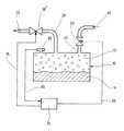
以下に、本発明による方法を、図1ないし2に示されている、内燃機関を備えた自動車内のタンク10を有するタンク装置により説明する。この方法は、自動車のタンク10に限定されず、むしろ任意の容器または種々の流体特に燃料に対するタンク装置において、および特に種々の分野におけるタンク装置のタンク通気系において、例えば化学工業において使用される容器においても、気密検査に使用可能である。In the following, the method according to the invention will be described with reference to the tank arrangement shown in FIGS. 1 and 2 and having a
気密性に関して検査されるべき、図1に略図で示されているタンク10はフレッシュ・エア供給配管40を有し、フレッシュ・エア供給配管40内に制御可能な遮断弁50が配置されている。このフレッシュ・エア供給配管40を介して、タンク10に、フレッシュ・エアが矢印45の方向に流入可能である。さらに、タンク10は吸引配管20を有し、吸引配管20内に電磁駆動真空ポンプ(ポンプ30)が配置されている。ポンプ30の代わりに、例えば機械駆動および/または油圧駆動真空源が設けられていてもよい。The
ポンプ30により、ガス混合物12は、矢印25の方向に、吸引配管20を介してタンク10から吸引される。ポンプ30は、制御ライン35を介して、制御ユニット70特にエンジン制御装置により操作可能且つ制御可能である。さらに、制御ユニット70により、制御ライン55を介して、遮断弁50の開閉操作が可能である。The
さらに、タンク10は圧力センサ60を有し、圧力センサ60により、タンク10内の圧力を測定可能である。圧力センサ60は、同じ圧力が作用しているタンク装置内の他の位置に配置されていてもよいことは明らかである。圧力センサ60の信号は信号ライン65を介して制御ユニット70に伝送される。Furthermore, the
圧力は、圧力センサ60を用いる代わりに、他の方法で、例えば圧力センサの特性を表わす、タンク装置および/またはポンプ30の任意の運転変数から決定されてもよい。
タンク10は、図1に例として示されているように、少なくとも一部が燃料11で満たされている。燃料11の上方にガス混合物12が存在する。ガス混合物12は特に燃料蒸気および空気を有している。タンクはガス混合物12のみで充満されていてもよい。Instead of using the
The
図2に示されている第2の実施態様においては、図1に示されている第1の実施態様と同じ構成部分には同じ符号が付けられているので、それらの説明に関しては、第1の実施態様の説明がそのまま参照される。この実施態様は、ポンプ30の代わりに制御可能なタンク通気弁30′が設けられていることにより第1の実施態様とは異なり、タンク通気弁30′により吸引配管20内のガス質量流量を制御可能である。ここで、吸引配管20は、図示されていない内燃機関の吸気管と結合されている。内燃機関が運転しているとき、タンク通気弁30′が少なくとも一部開かれている場合、吸気管内の負圧により、ガス混合物12は矢印25の方向にタンク10から吸引される。In the second embodiment shown in FIG. 2, the same components as those in the first embodiment shown in FIG. The description of the embodiment is referred to as it is. This embodiment is different from the first embodiment in that a controllable tank vent valve 30 'is provided in place of the
ここで、遮断弁50が閉じられ、および図1に示されているポンプ30により、ないし図2に示されているタンク通気弁30′を開くことにより、吸引配管20を介してガス混合物12が吸引された場合、タンク装置内特にタンク10内に負圧が形成される。Here, the shut-off
ここで本発明による気密検査を実行するために、図3に示されているように、本方法がステップ20からスタートされる。
最初にステップ210において遮断弁50が閉じられ、これによりフレッシュ・エア供給配管40は遮断され、したがってフレッシュ・エアはタンク10内に流入可能ではない。The method is now started from
First, in
それに続いてステップ220において、タンク10内の負圧の制御が行われる。このために、ポンプ30ないしタンク通気弁30′が図1ないし2に示されているように操作され、且つタンク10内に負圧が形成される。この場合、負圧は、例えばメーカー側で設定された所定の一定の値に制御される。(4) Subsequently, in
この制御過程により、燃料11のガス発生による、および/またはタンク装置の弾性構成部分の変形例えば収縮による負圧の低下が補償される。したがって、時間線図内にガス質量流量の低下が現われ、このガス質量流量の低下は、負圧を保持するために必要なポンプ30の排出能力の低下ないしタンク通気弁30′の開度の低減により検出可能である。
タンク装置内に非気密性が存在する場合、燃料11のガス発生がほとんど終了すると直ちに、一定に制御される負圧により、定常的に、非気密性による平均して一定の空気質量流量が設定される。燃料11の残余蒸発は負圧低下に僅かに寄与するにすぎない。
弾性構成部分はこれ以上収縮しないので、これによりさらに負圧の低下は行われない。吸引配管20内のガス質量流量は、ほぼ一定の空気質量流量であることから、定常状態にある。This control process compensates for a reduction in negative pressure due to gassing of the
If non-hermeticity exists in the tank device, as soon as the gas generation of the
Since the elastic component does not contract any further, this does not further reduce the negative pressure. Since the gas mass flow rate in the
ポンプ30ないしタンク通気弁30′は、定常状態において、平均して一定の操作変数で操作され、この場合、この操作変数は、制御ユニット70内で、圧力センサ60により決定されたタンク10内の圧力に対する信号から、それ自身既知の方法で決定される。ここで、操作変数は例えばポンプ電流である。しかしながら、ここで操作変数として回転速度等が使用されてもよい。電磁操作タンク通気装置30′は例えば周期的に操作されてもよく、このときにはサイクル周波数が操作変数である。In the steady state, the
ここでステップ230において、ガス質量流量が設定可能な限界値より大きいかどうかが検査され、この限界値は、例えば実験により予め決定され、且つ例えばメーカー側で設定されたものであり、この限界値は、タンク装置ないし燃料11の物理的および/または化学的性質例えば燃料11の残余蒸発に対して特有のものである。ガス質量流量が設定限界値より大きくない場合、ステップ240において、非気密性が存在しないこと、即ち特に非気密性による周囲からの空気の流入が可能ではないことが推測される。それに続いてこの方法はステップ280において終了される。Here, in
それとは逆に、ステップ230において、ガス質量流量が設定限界値より大きいことが特定された場合、ステップ250において、非気密性が存在することが推測される。それに続いてステップ260において、ステップ220において決定された操作変数から非気密性変数が計算される。Conversely, if it is determined in
計算された非気密性変数は、ステップ270において、図示されていない出力ユニットまたは制御ユニット70に伝送される。
それに続いてステップ280においてこの方法が終了される。The calculated non-hermetic variable is transmitted in
Subsequently, at
負圧の代わりにタンク10内に過圧が形成されてもよい。このために、このとき、ポンプ30またはタンク通気弁30′の代わりに対応過圧源が必要である。このときには、ガス発生の代わりにガス混合物12の凝縮が補償可能である。過 An overpressure may be formed in the
このように、上記実施形態は、容器(特に自動車タンク装置)の気密検査方法に関するものである。従来、タンクに加圧して、圧力低下を測定したり、基準漏れを並列に設けて、診断する方法があった。また、負圧にして、圧力上昇から診断する方法もあった。負圧にする場合、燃料の蒸発、タンク自体の弾性変形(収縮)が測定誤差となる。加圧にする場合、ガス混合物の凝縮、タンク自体の弾性変形(膨張)が診断誤差となる。この誤差要因を排除した方法および装置が上記実施形態である。タンク内に一定の負圧が達成されるように、真空ポンプ30または吸気管通気弁30′で、ガス質量流量が制御され、ガス質量流量が限界値より大きいときにタンクの非気密性が推測される。前記一定のガス質量流量から、非気密性変数を計算することができる。限界値は、容器の弾性、流体の残余蒸発、ガス混合物の残余凝縮の関数として設定することができる。タンク内に一定の加圧を形成するときは、ポンプを使うことができる。ポンプを使う例が第1の実施態様(図1)、吸気管通気弁を使う例が第2の実施態様(図2)、図3に、タンク気密検査方法の流れ図が示されている。As described above, the above embodiment relates to a method for inspecting the airtightness of a container (particularly, an automobile tank device). Conventionally, there has been a method of diagnosing by applying pressure to a tank and measuring a pressure drop or providing a reference leak in parallel. There has also been a method in which a negative pressure is applied and a diagnosis is made from an increase in pressure. In the case of a negative pressure, evaporation of fuel and elastic deformation (shrinkage) of the tank itself cause measurement errors. In the case of pressurization, condensation of the gas mixture and elastic deformation (expansion) of the tank itself result in a diagnosis error. The above-described embodiment is a method and an apparatus in which this error factor is eliminated. The gas mass flow is controlled by the
以上のように、上記実施形態は、容器(10、20、30、40、50)特に内燃機関を備えた自動車のタンク装置およびタンク通気装置の気密検査方法および装置において、実行されている物理的および/または化学的プロセスとは無関係に、容器(10、20、30、40、50)の非気密性を高い確実性で検出可能であり且つ非気密性変数を高い精度で決定可能なように、容器(10、20、30、40、50)の構成部分特にタンク(10)の弾性、および/または容器(10、20、30、40、50)内に存在する液体(11)のガス発生ないし容器(10、20、30、40、50)内に存在するガスまたはガス混合物(12)の凝縮の、容器(10、20、30、40、50)内の負圧または過圧への影響を低減させるために、容器(10、20、30、40、50)内に一定の負圧ないし過圧が達成されるようにガス質量流量が制御され、および設定可能な限界値よりも大きい、平均して一定のガス質量流量が設定された場合に、非気密性の存在が推測される。一定のガス質量流量を表わす信号から、非気密性変数が計算される。As described above, the above embodiment is implemented in a method and an apparatus for airtightness inspection of a container (10, 20, 30, 40, 50), particularly a tank device and a tank ventilation device of an automobile equipped with an internal combustion engine. And / or independent of the chemical process so that the tightness of the container (10, 20, 30, 40, 50) can be detected with high certainty and the tightness variable can be determined with high accuracy. The elasticity of the components of the container (10, 20, 30, 40, 50), in particular the tank (10), and / or the gassing of the liquid (11) present in the container (10, 20, 30, 40, 50). Or the effect of the condensation of the gas or gas mixture (12) present in the container (10, 20, 30, 40, 50) on the negative or overpressure in the container (10, 20, 30, 40, 50) Reduce In addition, the gas mass flow is controlled in such a way that a constant underpressure or overpressure is achieved in the container (10, 20, 30, 40, 50) and is, on average, constant, greater than a settable limit value When the gas mass flow rate is set, the existence of non-hermeticity is assumed. From the signal representing the constant gas mass flow, the non-hermetic variable is calculated.
このようにして、容器構成部分の弾性および/または容器内に存在する液体のガス発生ないし容器内に存在するガスまたはガス混合物の凝縮の、容器内の負圧ないし過圧への影響が低減され、これにより、実行されている物理的および/または化学的プロセスとは無関係に、容器の非気密性を高い確実性で検出可能であり且つ非気密性変数を高い精度で決定可能な、容器特に内燃機関を備えた自動車のタンク装置およびタンク通気装置の気密検査方法および装置を提供する。In this way, the effect of the elasticity of the container components and / or the gassing of the liquid present in the container or the condensation of the gas or gas mixture present in the container on the negative or overpressure in the container is reduced. This makes it possible to detect the non-hermeticity of the container with high certainty and to determine the non-hermetic variable with high accuracy independently of the physical and / or chemical processes being carried out. An airtightness inspection method and apparatus for a tank device and a tank ventilation device of an automobile having an internal combustion engine are provided.
10 タンク
11 流体(燃料)
12 ガス混合物
20 吸引配管
25 吸引(矢印)
30 ポンプ(圧力源)
30′ 通気弁(換言すれば、ガス抜き弁)
35、55 制御ライン
40 フレッシュ・エア供給配管(すなわち、外気供給配管)
45 供給(矢印)
50 遮断弁
60 圧力センサ
65 信号ライン
70 制御ユニット10
12
30 pump (pressure source)
30 'vent valve (in other words, vent valve)
35, 55
45 Supply (arrow)
50 Shut-off
Claims (10)
Translated fromJapanese一定の負圧ないし過圧が達成されるようにガス質量流量が制御され、および設定可能な限界値よりも大きい、平均して一定のガス質量流量が設定された場合に、非気密性の存在が推測されることを特徴とする容器の気密検査方法。The supply to the container or the discharge from the container (45) is shut off, the container is set to a configurable negative or overpressure with respect to atmospheric pressure, and the gas mass flow required for this, in particular air In a method for checking the tightness of a tank device and a tank ventilation device of a container, in particular a motor vehicle with an internal combustion engine, wherein a first signal representative of the mass flow is measured.
The gas mass flow is controlled such that a constant underpressure or overpressure is achieved, and the presence of non-hermeticity when an average constant gas mass flow is set which is greater than a configurable limit. Airtightness inspection method for containers, characterized in that:
圧力源(30;30′)が、設定可能な平均して一定の負圧ないし過圧を保持するように制御可能であることと、および
制御のために圧力源(30;30′)を操作可能な操作変数から、非気密性変数が計算可能であることと、
を特徴とする容器の気密検査装置。A supply or discharge (45), in particular a shut-off valve (50) for shutting off the supply of fresh air to the container, and a configurable, negative or overpressure with respect to atmospheric pressure on the container. An airtightness inspection system for a tank device and a tank ventilation device for a motor vehicle equipped with a container, particularly an internal combustion engine, for performing the method according to any one of claims 1 to 6, provided with a pressure source (30; 30 '). ,
The pressure source (30; 30 ') is controllable to maintain a configurable and constant negative or overpressure, and the pressure source (30; 30') is operated for control That the non-hermetic variables can be calculated from the possible manipulated variables,
An airtightness inspection device for containers.
Applications Claiming Priority (1)
| Application Number | Priority Date | Filing Date | Title |
|---|---|---|---|
| DE10243807ADE10243807B4 (en) | 2002-09-20 | 2002-09-20 | Method and device for leak testing a container |
Publications (2)
| Publication Number | Publication Date |
|---|---|
| JP2004117355Atrue JP2004117355A (en) | 2004-04-15 |
| JP4353758B2 JP4353758B2 (en) | 2009-10-28 |
Family
ID=31969330
Family Applications (1)
| Application Number | Title | Priority Date | Filing Date |
|---|---|---|---|
| JP2003327598AExpired - Fee RelatedJP4353758B2 (en) | 2002-09-20 | 2003-09-19 | Container airtightness inspection method and apparatus |
Country Status (4)
| Country | Link |
|---|---|
| US (1) | US6840234B2 (en) |
| JP (1) | JP4353758B2 (en) |
| KR (1) | KR20040025844A (en) |
| DE (1) | DE10243807B4 (en) |
Cited By (2)
| Publication number | Priority date | Publication date | Assignee | Title |
|---|---|---|---|---|
| JP2007536559A (en)* | 2005-01-10 | 2007-12-13 | モコン・インコーポレーテッド | Apparatus and method for detecting leaks in hermetically sealed packages |
| KR20110072610A (en)* | 2009-12-23 | 2011-06-29 | 두산인프라코어 주식회사 | Pressure holding device of hydraulic oil tank |
Families Citing this family (7)
| Publication number | Priority date | Publication date | Assignee | Title |
|---|---|---|---|---|
| CN100416252C (en)* | 2005-12-09 | 2008-09-03 | 北京北方微电子基地设备工艺研究中心有限责任公司 | Method for detecting leak rate of air passage cabinet of etching machine |
| DE102006026408B4 (en)* | 2006-06-07 | 2009-11-19 | Dr. Ing. H.C. F. Porsche Aktiengesellschaft | Method for determining a fuel spill on a fuel tank |
| DE102012204975A1 (en)* | 2012-03-28 | 2013-10-02 | Robert Bosch Gmbh | Method for injection calculation for an internal combustion engine |
| CN103728124A (en)* | 2013-06-27 | 2014-04-16 | 四川海普流体技术有限公司 | Vehicle-mounted pressure testing equipment |
| US9574807B2 (en)* | 2013-11-13 | 2017-02-21 | Mahle International Gmbh | Thermally driven condenser unit and adsorption heat or refrigeration plant |
| US20230139875A1 (en)* | 2021-10-29 | 2023-05-04 | Robert Bosch Gmbh | Vacuum-Based Leak Detection |
| DE102023206302A1 (en)* | 2023-07-03 | 2025-01-09 | Vitesco Technologies GmbH | Method for modeling an input current of a pump and control unit |
Family Cites Families (10)
| Publication number | Priority date | Publication date | Assignee | Title |
|---|---|---|---|---|
| US5092259A (en)* | 1989-07-10 | 1992-03-03 | Mo Husain | Inert gas control in a system to reduce spillage of oil due to rupture of ship's tank |
| DE4208585A1 (en)* | 1991-03-19 | 1992-09-24 | Rolf Pohlmann | Testing gas pipe seals for suitability for natural gas - using test gas hold at raised pressure during test interval where gas supply is lower pressure town gas |
| DE4317634A1 (en)* | 1993-05-27 | 1994-12-01 | Bosch Gmbh Robert | Method and device for checking the tightness of a tank venting installation |
| JP3106816B2 (en)* | 1993-10-30 | 2000-11-06 | スズキ株式会社 | Failure diagnosis device for evaporative system |
| US5850819A (en)* | 1994-12-09 | 1998-12-22 | Mitsubishi Jidosha Kogyo Kabushiki Kaisha | Fuel evaporative emission treatment system |
| JP4045665B2 (en)* | 1998-09-02 | 2008-02-13 | 日産自動車株式会社 | Evaporative fuel processing device for internal combustion engine |
| DE10006185C1 (en)* | 2000-02-11 | 2001-06-13 | Bosch Gmbh Robert | Seal testing method for automobile fuel tank system has measurement interval extended when leak is indicated for verification before leakage signal is supplied |
| DE10006186C1 (en)* | 2000-02-11 | 2001-06-13 | Bosch Gmbh Robert | Seal testing method for automobile fuel tank system, has measurement repeated when leak is indicated for verification before leakage signal is supplied |
| DE10018441B4 (en)* | 2000-04-13 | 2005-12-29 | Robert Bosch Gmbh | Method and device for environmentally sound leak testing of a container |
| JP2002130061A (en)* | 2000-10-20 | 2002-05-09 | Denso Corp | Evaporative fuel processing system |
- 2002
- 2002-09-20DEDE10243807Apatent/DE10243807B4/ennot_activeExpired - Fee Related
- 2003
- 2003-09-19JPJP2003327598Apatent/JP4353758B2/ennot_activeExpired - Fee Related
- 2003-09-19KRKR1020030064986Apatent/KR20040025844A/ennot_activeCeased
- 2003-09-22USUS10/664,942patent/US6840234B2/ennot_activeExpired - Fee Related
Cited By (3)
| Publication number | Priority date | Publication date | Assignee | Title |
|---|---|---|---|---|
| JP2007536559A (en)* | 2005-01-10 | 2007-12-13 | モコン・インコーポレーテッド | Apparatus and method for detecting leaks in hermetically sealed packages |
| KR20110072610A (en)* | 2009-12-23 | 2011-06-29 | 두산인프라코어 주식회사 | Pressure holding device of hydraulic oil tank |
| KR101648981B1 (en) | 2009-12-23 | 2016-08-17 | 두산인프라코어 주식회사 | Pressure maintenance apparatus for oil tank |
Also Published As
| Publication number | Publication date |
|---|---|
| US20040055369A1 (en) | 2004-03-25 |
| DE10243807A1 (en) | 2004-04-01 |
| DE10243807B4 (en) | 2013-08-01 |
| JP4353758B2 (en) | 2009-10-28 |
| KR20040025844A (en) | 2004-03-26 |
| US6840234B2 (en) | 2005-01-11 |
Similar Documents
| Publication | Publication Date | Title |
|---|---|---|
| KR100234603B1 (en) | Method and apparatus for checking the functional capability of the tank vent device of the vehicle | |
| US9399970B2 (en) | Combination pressure- and vacuum-based EVAP leak detection method | |
| US11326559B2 (en) | Leakage detector for fuel vapor treatment device | |
| CN101576031B (en) | Leak diagnostic apparatus for an evaporative emission control system | |
| US20170159588A1 (en) | Fuel vapor processing system and method for operating fuel vapor processing system | |
| US7219535B2 (en) | Leakage diagnosis apparatus for fuel vapor purge system and method thereof | |
| US7448257B2 (en) | Leak check apparatus for fuel vapor processing apparatus | |
| US8751174B2 (en) | Method for determining the size of a leak | |
| JP2003057143A (en) | Method and apparatus for inspecting airtightness of container especially automobile tank ventilating device, and diagnostic unit | |
| JP6316347B2 (en) | Blockage detection apparatus and blockage detection method | |
| JP2000282972A (en) | Failure diagnosing device for evaporated fuel processing device | |
| JP2004117355A (en) | Airtightness inspecting method for container and its device | |
| US10899223B2 (en) | Method for testing the tightness of a fuel supply system | |
| US10712228B2 (en) | Blockage diagnosis device | |
| JP2000065671A (en) | Method for inspecting functionality of venting apparatus for container, particularly tank | |
| JP2019078172A (en) | Fuel residual estimation device and abnormality diagnosis device of fuel vapor tight system | |
| US11118958B2 (en) | System for determining a filling level in a fuel tank | |
| JP4278329B2 (en) | Airtight inspection method for vehicle tank device | |
| US10914271B1 (en) | Leak diagnosis system using purge pump of active purge system and leak diagnosis method using purge pump of active purge system | |
| CN114761777A (en) | Determining the size of a leak in a fuel tank system | |
| US11156190B2 (en) | Occlusion diagnosis device | |
| JP7115209B2 (en) | Evaporative fuel processing device | |
| JPH09133598A (en) | Air-pressure testing method for functionality of tank-bent device and method for testing air pressure and airtightness of container | |
| JP2010071198A (en) | Device and method for diagnosing failure of in-tank canister system | |
| JP2000120495A (en) | Evaporated gas purging system |
Legal Events
| Date | Code | Title | Description |
|---|---|---|---|
| A621 | Written request for application examination | Free format text:JAPANESE INTERMEDIATE CODE: A621 Effective date:20060914 | |
| A131 | Notification of reasons for refusal | Free format text:JAPANESE INTERMEDIATE CODE: A131 Effective date:20081201 | |
| A601 | Written request for extension of time | Free format text:JAPANESE INTERMEDIATE CODE: A601 Effective date:20090227 | |
| A602 | Written permission of extension of time | Free format text:JAPANESE INTERMEDIATE CODE: A602 Effective date:20090304 | |
| A601 | Written request for extension of time | Free format text:JAPANESE INTERMEDIATE CODE: A601 Effective date:20090331 | |
| A602 | Written permission of extension of time | Free format text:JAPANESE INTERMEDIATE CODE: A602 Effective date:20090403 | |
| A601 | Written request for extension of time | Free format text:JAPANESE INTERMEDIATE CODE: A601 Effective date:20090430 | |
| A602 | Written permission of extension of time | Free format text:JAPANESE INTERMEDIATE CODE: A602 Effective date:20090508 | |
| A521 | Written amendment | Free format text:JAPANESE INTERMEDIATE CODE: A523 Effective date:20090601 | |
| TRDD | Decision of grant or rejection written | ||
| A01 | Written decision to grant a patent or to grant a registration (utility model) | Free format text:JAPANESE INTERMEDIATE CODE: A01 Effective date:20090629 | |
| A01 | Written decision to grant a patent or to grant a registration (utility model) | Free format text:JAPANESE INTERMEDIATE CODE: A01 | |
| A61 | First payment of annual fees (during grant procedure) | Free format text:JAPANESE INTERMEDIATE CODE: A61 Effective date:20090728 | |
| R150 | Certificate of patent or registration of utility model | Free format text:JAPANESE INTERMEDIATE CODE: R150 | |
| FPAY | Renewal fee payment (event date is renewal date of database) | Free format text:PAYMENT UNTIL: 20120807 Year of fee payment:3 | |
| FPAY | Renewal fee payment (event date is renewal date of database) | Free format text:PAYMENT UNTIL: 20130807 Year of fee payment:4 | |
| R250 | Receipt of annual fees | Free format text:JAPANESE INTERMEDIATE CODE: R250 | |
| R250 | Receipt of annual fees | Free format text:JAPANESE INTERMEDIATE CODE: R250 | |
| R250 | Receipt of annual fees | Free format text:JAPANESE INTERMEDIATE CODE: R250 | |
| LAPS | Cancellation because of no payment of annual fees |