JP2004109222A - Endoscope apparatus - Google Patents
Endoscope apparatusDownload PDFInfo
- Publication number
- JP2004109222A JP2004109222AJP2002268729AJP2002268729AJP2004109222AJP 2004109222 AJP2004109222 AJP 2004109222AJP 2002268729 AJP2002268729 AJP 2002268729AJP 2002268729 AJP2002268729 AJP 2002268729AJP 2004109222 AJP2004109222 AJP 2004109222A
- Authority
- JP
- Japan
- Prior art keywords
- unit
- bending
- section
- endoscope apparatus
- grip
- Prior art date
- Legal status (The legal status is an assumption and is not a legal conclusion. Google has not performed a legal analysis and makes no representation as to the accuracy of the status listed.)
- Pending
Links
- 238000005452bendingMethods0.000claimsabstractdescription70
- 238000003780insertionMethods0.000claimsabstractdescription59
- 230000037431insertionEffects0.000claimsabstractdescription59
- 238000007689inspectionMethods0.000claimsdescription12
- 230000001225therapeutic effectEffects0.000abstract1
- 230000003287optical effectEffects0.000description9
- 230000000694effectsEffects0.000description7
- 238000005286illuminationMethods0.000description7
- 238000004804windingMethods0.000description2
- 239000000470constituentSubstances0.000description1
- 239000004973liquid crystal related substanceSubstances0.000description1
- 238000012986modificationMethods0.000description1
- 230000004048modificationEffects0.000description1
- 239000000126substanceSubstances0.000description1
Images


Classifications
- A—HUMAN NECESSITIES
- A61—MEDICAL OR VETERINARY SCIENCE; HYGIENE
- A61B—DIAGNOSIS; SURGERY; IDENTIFICATION
- A61B1/00—Instruments for performing medical examinations of the interior of cavities or tubes of the body by visual or photographical inspection, e.g. endoscopes; Illuminating arrangements therefor
- A61B1/005—Flexible endoscopes
- A61B1/0051—Flexible endoscopes with controlled bending of insertion part
- A—HUMAN NECESSITIES
- A61—MEDICAL OR VETERINARY SCIENCE; HYGIENE
- A61B—DIAGNOSIS; SURGERY; IDENTIFICATION
- A61B1/00—Instruments for performing medical examinations of the interior of cavities or tubes of the body by visual or photographical inspection, e.g. endoscopes; Illuminating arrangements therefor
- A61B1/00002—Operational features of endoscopes
- A61B1/00039—Operational features of endoscopes provided with input arrangements for the user
- A61B1/00042—Operational features of endoscopes provided with input arrangements for the user for mechanical operation
- A—HUMAN NECESSITIES
- A61—MEDICAL OR VETERINARY SCIENCE; HYGIENE
- A61B—DIAGNOSIS; SURGERY; IDENTIFICATION
- A61B1/00—Instruments for performing medical examinations of the interior of cavities or tubes of the body by visual or photographical inspection, e.g. endoscopes; Illuminating arrangements therefor
- A61B1/00002—Operational features of endoscopes
- A61B1/00043—Operational features of endoscopes provided with output arrangements
- A61B1/00045—Display arrangement
- A61B1/00052—Display arrangement positioned at proximal end of the endoscope body
- A—HUMAN NECESSITIES
- A61—MEDICAL OR VETERINARY SCIENCE; HYGIENE
- A61B—DIAGNOSIS; SURGERY; IDENTIFICATION
- A61B1/00—Instruments for performing medical examinations of the interior of cavities or tubes of the body by visual or photographical inspection, e.g. endoscopes; Illuminating arrangements therefor
- A61B1/00147—Holding or positioning arrangements
- A61B1/0016—Holding or positioning arrangements using motor drive units
- A—HUMAN NECESSITIES
- A61—MEDICAL OR VETERINARY SCIENCE; HYGIENE
- A61B—DIAGNOSIS; SURGERY; IDENTIFICATION
- A61B1/00—Instruments for performing medical examinations of the interior of cavities or tubes of the body by visual or photographical inspection, e.g. endoscopes; Illuminating arrangements therefor
- A61B1/012—Instruments for performing medical examinations of the interior of cavities or tubes of the body by visual or photographical inspection, e.g. endoscopes; Illuminating arrangements therefor characterised by internal passages or accessories therefor
- A61B1/018—Instruments for performing medical examinations of the interior of cavities or tubes of the body by visual or photographical inspection, e.g. endoscopes; Illuminating arrangements therefor characterised by internal passages or accessories therefor for receiving instruments
Landscapes
- Life Sciences & Earth Sciences (AREA)
- Health & Medical Sciences (AREA)
- Surgery (AREA)
- Engineering & Computer Science (AREA)
- Biophysics (AREA)
- Medical Informatics (AREA)
- Nuclear Medicine, Radiotherapy & Molecular Imaging (AREA)
- Optics & Photonics (AREA)
- Pathology (AREA)
- Radiology & Medical Imaging (AREA)
- Veterinary Medicine (AREA)
- Biomedical Technology (AREA)
- Heart & Thoracic Surgery (AREA)
- Physics & Mathematics (AREA)
- Molecular Biology (AREA)
- Animal Behavior & Ethology (AREA)
- General Health & Medical Sciences (AREA)
- Public Health (AREA)
- Mechanical Engineering (AREA)
- Endoscopes (AREA)
- Instruments For Viewing The Inside Of Hollow Bodies (AREA)
Abstract
Description
Translated fromJapanese【0001】
【発明の属する技術分野】
本発明は、主に工業用分野で使用され、パイプ内などの検査対象空間内に挿入されてその検査対象空間内などを観察する内視鏡装置に関する。
【0002】
【従来の技術】
一般に、工業用の内視鏡には、パイプ内などの検査対象空間内に挿入される細長い挿入部の基端部に手元側の操作部が連結された構成が多い。ここで、挿入部の最先端部側には観察用の観察光学系や、照明光学系などが組み込まれたヘッド部が設けられている。さらに、このヘッド部の後方には上下方向、左右方向、およびこれらを組み合わせた任意の方向に湾曲変形可能な湾曲部が配設されている。この湾曲部には複数、例えば4本の湾曲操作ワイヤの先端部が固定されている。各湾曲操作ワイヤの基端部は手元側に延出され、手元側の操作部に配設された湾曲操作機構に連結されている。
【0003】
また、手元側の操作部には湾曲操作機構を駆動して湾曲部を湾曲操作する操作ノブが配設されている。そして、この操作ノブの回動操作に基いて湾曲操作機構が駆動され、湾曲操作ワイヤが牽引操作されて各湾曲操作ワイヤの牽引動作に連動して湾曲部が操作ノブの回動操作に応じて湾曲操作されるようになっている。
【0004】
また、内視鏡の挿入部には鉗子などの処置具類を挿入するための内部チャンネル(処置具挿通路)が配設されている。挿入部のヘッド部にはこの内部チャンネルの先端側開口端が形成されている。さらに、操作部には、この内部チャンネルの鉗子口(基端側開口端)が配設されている。
【0005】
また、近年は湾曲機構の電動化が進み、その湾曲入力手段も手動による操作ノブから、例えば、特許文献1に示されているように傾け角度に相当した信号を発するジョイスティックなどの電動湾曲操作式の湾曲入力手段に置き換わる場合がある。この場合には必ずしも挿入部の後端側の操作部に常時、ジョイスティックなどの操作入力手段が固定されている必要はない。
【0006】
そこで、ジョイスティックなどの湾曲入力手段を挿入部の後端側の操作部とは別の場所に独立に設けることが考えられている。この場合には、内視鏡装置の使用時に湾曲操作のみを行ないたい場合は、操作部とは別の場所でジョイスティックなどの湾曲入力装置だけを操作し、挿入部は任意の位置で把持すればよい。また、鉗子操作のみ行ないたい場合には、操作部を把持した状態で鉗子口またはその近傍で鉗子類を操作すればよい。
【0007】
【特許文献1】
米国特許第5,373,317号明細書
【0008】
【発明が解決しようとする課題】
しかしながら、ジョイスティックなどの電動湾曲操作式の湾曲入力手段を操作部とは別の場所に配設した場合にはジョイスティックなどの湾曲入力手段の操作による湾曲部の湾曲操作と、鉗子口からの鉗子操作の両方を行ないたい場合に、その操作を別の場所で別々に行なう必要がある。そのため、操作部に、手動による操作ノブと内部チャンネルの鉗子口とが配設されている従来構成の内視鏡に比べてその操作が行ない難い問題がある。
【0009】
本発明は上記事情に着目してなされたもので、その目的は、電動湾曲操作式の湾曲入力手段の操作による湾曲部の湾曲操作と、処置具などの操作の両方を簡単に行なうことができ、操作性の良い内視鏡装置を提供することにある。
【0010】
【課題を解決するための手段】
請求項1の発明は、検査対象空間内に挿入される可撓性を有する細長い挿入部に湾曲部が配設され、
前記湾曲部を湾曲操作するための湾曲操作手段と把持部とを備えた操作部が前記挿入部の基端側に配置された内視鏡装置において、
前記挿入部の先端側に開口する先端側開口端と前記挿入部の基端側に開口する基端側開口端との間を連通する処置具挿通路を前記挿入部に設け、
前記操作部の把持部に前記処置具挿通路の基端側開口端を設けたことを特徴とする内視鏡装置である。
【0011】
そして、本請求項1の発明では、操作部の湾曲操作手段によって湾曲部を湾曲操作するとともに、その近傍位置の把持部の処置具挿通路の基端側開口端で処置具などの操作を行なうことができるようにしたものである。
【0012】
請求項2の発明は、前記把持部は、内視鏡の観察像を表示する表示手段を有することを特徴とする請求項1に記載の内視鏡装置である。
【0013】
そして、本請求項2の発明では、把持部の表示手段によって内視鏡の観察像を表示するようにしたものである。
【0014】
請求項3の発明は、前記表示手段は、表示パネルと、この表示パネルを支持する枠体とを備え、
前記処置具挿通路の基端側開口端は、前記枠体に配置されていることを特徴とする請求項2に記載の内視鏡装置である。
【0015】
そして、本請求項3の発明では、表示手段の表示パネルを支持する枠体の処置具挿通路の基端側開口端で処置具などの操作を行なうことができるようにしたものである。
【0016】
請求項4の発明は、前記処置具挿通路の基端側開口端は、前記把持部の裏面に配置されていることを特徴とする請求項1に記載の内視鏡装置である。
【0017】
そして、本請求項4の発明では、把持部の裏面の処置具挿通路の基端側開口端で処置具などの操作を行なうことができるようにしたものである。
【0018】
【発明の実施の形態】
以下、本発明の第1の実施の形態を図1(A),(B)乃至図9を参照して説明する。図1(A)は本実施の形態の工業用内視鏡装置1を示すものである。この内視鏡装置1には内視鏡の構成要素をを備えた内視鏡装置本体101と、この内視鏡装置本体101を着脱可能に収納する内視鏡収納ケース102とが設けられている。内視鏡装置本体101にはスコープ部2と、光源装置やカメラコントロールユニット(CCU)などを備えた固定ユニット100とが設けられている。なお、固定ユニット100には電源コード104の基端部が接続され、この電源コード104の先端にプラグ104aが接続されている。
【0019】
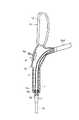
さらに、スコープ部2は少なくとも検査対象空間内に挿入される可撓性を有する細長い挿入部2aと、操作部2bと、ユニバーサルコード2cとを有している。ここで、挿入部2aは、最先端位置に配置され、観察用の観察光学系や、照明光学系などが組み込まれたヘッド部2a1と、遠隔的に湾曲操作可能な湾曲部2a2と、細長い可撓管部2a3とから構成されている。そして、ヘッド部2a1と可撓管部2a3との間に湾曲部2a2が介設されている。
【0020】
また、図1(B)に示すようにヘッド部2a1の先端面には照明光学系用の照明窓3と、観察光学系用の観察窓4と、挿入部2aの内部に配設された内部チャンネル(処置具挿通路)5(図3に示す)の先端側開口端6などがそれぞれ配設されている。さらに、挿入部2aの内部には照明光学系に照明光を伝送する図示しないライトガイドと、観察光学系に配設された例えばCCDなどの撮像素子に接続された電気コードと、湾曲部2a2を湾曲操作する湾曲ワイヤなどがそれぞれ配設されている。
【0021】
また、挿入部2aの可撓管部2a3の基端部には操作部2bの先端部が連結されている。図2は操作部2bの外観を示すものである。この操作部2bには少なくとも図4に示すように使用者が片手で把持可能なグリップ部(把持部)7が設けられている。このグリップ部7には、スコープ部2の湾曲部2a2の湾曲方向を上下左右方向に遠隔的に湾曲操作するための電動湾曲操作式の湾曲入力手段であるジョイスティック(湾曲操作手段)8と、パワーボタン9とが主に設けられている。
【0022】
ここで、ジョイスティック8には基端部が回動支点を介して回動可能に支持された操作レバー8aが設けられている。そして、この操作レバー8aの傾け角度に相当した信号を発するようになっている。
【0023】
さらに、操作部2bのグリップ部7の上部表面には、モニター部(表示手段)10と、内部チャンネル5の鉗子口(基端側開口端)11とが設けられている。ここで、モニター部10には例えば液晶ディスプレイ(LCD)などの表示パネル12と、この表示パネル12を支持する枠体13とが設けられている。
【0024】
また、モニター部10は図3に示すようにグリップ部7のケーシング7aの平面に対して略平行に配置されている。ここで、モニター部10を斜めに傾斜させた状態で組み付けてもよい。なお、ケーシング7aにモニター部10の傾斜角度を任意に変更可能な支持機構を設けても良い。
【0025】
さらに、グリップ部7のケーシング7aにはモニター部10の下端部とジョイスティック8の近傍位置に内部チャンネル5の鉗子口11を形成する管状の鉗子口構成部材14が固定されている。そして、この鉗子口構成部材14の内端部に内部チャンネル5の基端側開口部5aが連結固定されている。なお、鉗子口構成部材14はジョイスティック8の作動領域と干渉しない位置に配置されている。さらに、鉗子口構成部材14はグリップ部7の端末部側(操作者側)に向けて開口するよう配置されていてもよい。
【0026】
また、グリップ部7の下端部にはユニバーサルコード2cの先端部との連結部が設けられている。このユニバーサルコード2cの内部には挿入部2a側から延出されるライトガイドと、CCDから出力される画像信号伝送用の電気コードと、モニター部10の表示パネル12に接続された電気コードなどが延設されている。
【0027】
また、ユニバーサルコード2cの基端部にはコネクタ15が設けられている。このコネクタ15にはライトガイドの接続端部や、電気コードなどの接続端子などが設けられている。そして、このコネクタ15は固定ユニット100に着脱可能に連結されるようになっている。
【0028】
また、固定ユニット100には電源部と、光源装置と、カメラコントロールユニットなどが内蔵されている。そして、コネクタ15が固定ユニット100に連結された際に、コネクタ15のライトガイドの接続端部が光源装置に接続され、光源装置から出射される照明光がライトガイドの接続端部に入射されるようになっている。さらに、コネクタ15の電気コードなどの接続端子などはカメラコントロールユニットに接続されるようになっている。
【0029】
そして、CCDで撮像された内視鏡観察像の画像データは電気信号に変換されて電気コードを介してカメラコントロールユニットに伝送されるようになっている。このとき、カメラコントロールユニットで映像信号に変換されたのち、このカメラコントロールユニットからの出力信号は電気コードを介してモニター部10の表示パネル12に入力されるようになっている。これにより、モニター部10の表示パネル12に内視鏡観察像が表示されるようになっている。
【0030】
また、本実施の形態のスコープ部2の湾曲部2a2の湾曲駆動機構の駆動モータは操作部2bのグリップ部7内や、コネクタ15内に設けられていてもよく、または固定ユニット100内に設けられていても良い。なお、コネクタ15内や固定ユニット100内に湾曲駆動機構の駆動モータが配置されている場合にはこの湾曲駆動機構の駆動モータの駆動力を伝達する部材、例えばアングルワイヤがユニバーサルコード2cの内部に挿通されている。
【0031】
また、内視鏡収納ケース102には上面が開口された箱型のケース本体102aと、このケース本体102aの上面開口部を開閉する蓋102bとが設けられている。この蓋102bは図示しないヒンジ部を介してケース本体102aの上面開口部の一側部に回動可能に連結されている。
【0032】
さらに、ケース本体102aの内部は2室103a,103bに仕切られている。そして、第1の収納室103a内には内視鏡装置本体101の固定ユニット100が収納され、第2の収納室103b内にはスコープ部2の挿入部2aと、操作部2bと、ユニバーサルコード2cとが例えば略リング状に丸く束ねた状態で収納されるようになっている。
【0033】
次に、上記構成の作用について説明する。本実施の形態の工業用内視鏡装置1の使用時には操作部2bのグリップ部7が使用者によって片手で把持される。このとき、図4や、図5に示すように使用者の片手によってグリップ部7全体を把持する状態、或いは図7に示すように使用者の両手によってグリップ部7の上部から下部にかけてを把持する状態、或いは図6に示すように使用者の片手によってグリップ部7の下部を把持する状態など様々な形態で把持してよい。この状態で、スコープ部2の挿入部2aが検査対象空間内に挿入されて検査対象空間内の内視鏡検査が行なわれる。
【0034】
また、内視鏡検査時には、図8に示すようにヘッド部2a1の観察光学系のCCDで撮像された内視鏡観察像の画像データは電気信号に変換されて電気コードを介してカメラコントロールユニットに伝送される。このとき、カメラコントロールユニットで映像信号に変換されたのち、このカメラコントロールユニットからの出力信号は電気コードを介してモニター部10の表示パネル12に入力される。これにより、モニター部10の表示パネル12に内視鏡観察像が表示される。なお、図8はタービンなどの被検体の検査対象空間内にスコープ部2の挿入部2aを挿入して被検体の検査対象空間内におけるブレード16の亀裂部17などを観察している状態を示している。
【0035】
さらに、内視鏡検査中は、モニター部10の表示パネル12の内視鏡観察像を目視しながら操作部2bのジョイスティック8が操作される。この場合、操作部2bのグリップ部7が使用者によって片手で把持されたままの状態で、図8に示すように片手の指でジョイスティック8の操作レバー8aを操作する。このとき、操作レバー8aを任意の方向に傾ける操作によってスコープ部2の湾曲部2a2の湾曲方向を操作レバー8aの操作方向と対応する方向に遠隔的に湾曲操作させることができる。
【0036】
また、図9に示すように鉗子などの処置具18を使用する場合には右手で処置具18を鉗子口構成部材14の鉗子口11に挿入する操作を行なう。このとき、図7に示すように鉗子口構成部材14の鉗子口11は、モニター部10の表示パネル12およびジョイスティック8の近傍位置に配置されているので、表示パネル12の内視鏡観察像と、左手による湾曲操作と、右手による処置具18のワイヤ18aの操作とを同時に目視しながらその操作が行なわれる。そして、この処置具18によって異物の回収作業などが行なわれる。
【0037】
そこで、上記構成のものにあっては次の効果を奏する。すなわち、本実施の形態の工業用内視鏡装置1では、操作部2bのグリップ部7に鉗子口構成部材14の鉗子口11を設け、この鉗子口11をモニター部10の表示パネル12およびジョイスティック8の近傍位置に配置している。そのため、表示パネル12の内視鏡観察像と、左手によるジョイスティック8の操作と、右手による処置具18の操作とを同時に目視しながらその操作を行なうことができる。その結果、左手によるジョイスティック8の操作による湾曲操作に加え、右手による処置具18の操作も操作部2bのグリップ部7上でできるため、その操作が単純で済むという効果がある。
【0038】
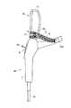
また、図10および図11は本発明の第2の実施の形態を示すものである。本実施の形態は第1の実施の形態(図1(A),(B)乃至図9参照)の工業用内視鏡装置1の操作部2bの構成を次の通り変更したものである。なお、本実施の形態では工業用内視鏡装置1の基本構成は第1の実施形態とほぼ同様なので、第1の実施形態と同一部分には同一の符号を付してその説明を省略する。
【0039】
すなわち、本実施の形態の操作部2bではモニター部10の枠体13上に鉗子口11を設けている。ここで、鉗子口11の鉗子口構成部材14は図10に示すように枠体13の下端部一側部に配置されている。そして、図11に示すようにこの鉗子口構成部材14の内端部に内部チャンネル5の基端側開口部5aが連結固定されている。
【0040】
そこで、上記構成の本実施の形態の操作部2bではモニター部10の枠体13における枠体13の下端部一側部に鉗子口11を設けたので、操作者により近い面に鉗子口11を配置することができる。そのため、鉗子などの処置具18の挿管を行ない易い効果がある。
【0041】
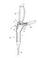
また、図12は本発明の第3の実施の形態を示すものである。本実施の形態は第1の実施の形態(図1(A),(B)乃至図9参照)の工業用内視鏡装置1の操作部2bの構成を次の通り変更したものである。
【0042】
すなわち、本実施の形態の操作部2bではグリップ部7のケーシング7aの裏面に下向きに開口する鉗子口11を設けている。この鉗子口11はグリップ部7の裏面におけるジョイスティック8と対応する位置よりも後方位置に配置されている。
【0043】
そこで、上記構成の本実施の形態の操作部2bではグリップ部7のケーシング7aの裏面に下向きに開口する鉗子口11を設けている。そのため、この鉗子口11に挿通された鉗子などの処置具18の基端側部分、すなわち、鉗子口11の外側に延出されている部分が下向きにだらりと垂れ下がっても、この垂れ下がった処置具18の基端側部分はグリップ部7の裏面側に配置されているので、ジョイスティック8の操作の邪魔にならない効果がある。
【0044】
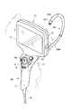
また、図13および図14は本発明の第4の実施の形態を示すものである。本実施の形態は第1の実施の形態(図1(A),(B)乃至図9参照)の工業用内視鏡装置1の操作部2bの構成を次の通り変更したものである。
【0045】
すなわち、本実施の形態の操作部2bではモニター部10における枠体13の右側部位置に鉗子口11を設けている。ここで、図14に示すように枠体13の側部位置と可撓管部2a3の基端部位置との間にはパイプ状のチューブ支持部材19が設けられている。このチューブ支持部材19の先端部位置に鉗子口11の鉗子口構成部材14が固定されている。そして、内部チャンネル5の基端部はこのチューブ支持部材19の下端部からチューブ支持部材19の内部に延出され、この内部チャンネル5の基端側開口部5aが鉗子口構成部材14の内端部に連結固定されている。
【0046】
そこで、上記構成の本実施の形態の操作部2bではモニター部10における枠体13の側部位置に鉗子口11を設けているので、鉗子口11の位置はジョイスティック8の操作レバー8aの操作範囲から離れた位置に配置されている。そのため、鉗子口11がジョイスティック8の操作レバー8aの操作の邪魔にならない効果がある。なお、鉗子口11は必ずしもモニター部10における枠体13の右側部位置に配置する必要はなく、例えばモニター部10における枠体13の上端位置、左側部位置に配置する構成にしてもよい。
【0047】
また、図15および図16は本発明の第5の実施の形態を示すものである。本実施の形態は第1の実施の形態(図1(A),(B)乃至図9参照)の工業用内視鏡装置1の操作部2bの構成を次の通り変更したものである。
【0048】
すなわち、本実施の形態の操作部2bではグリップ部7のケーシング7aにおける下端側の端末部にケーシング7aの下方向きに開口する鉗子口11を設けている。
【0049】
そこで、上記構成の本実施の形態の操作部2bでは鉗子口11に挿通された鉗子などの処置具18の基端側部分、すなわち、鉗子口11の外側に延出されている部分が下向きにだらりと垂れ下がっても、この垂れ下がった処置具18の基端側部分はグリップ部7のケーシング7aにおける下端側の端末部側に配置されているので、ジョイスティック8の操作の邪魔にならない効果がある。
【0050】
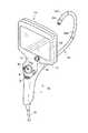
また、図17は本発明の第6の実施の形態を示すものである。本実施の形態は第5の実施の形態(図15および図16参照)の工業用内視鏡装置1の操作部2bの構成を次の通り変更したものである。
【0051】
すなわち、本実施の形態の操作部2bでは第5の実施の形態のモニター部10をグリップ部21に対して着脱可能に連結したものである。ここで、グリップ部21の上端部にはモニター部取付け穴部22が形成されている。このモニター部取付け穴部22にはモニター部10の下部に突設された連結部10aが着脱可能に連結されるようになっている。
【0052】
そこで、上記構成の本実施の形態ではグリップ部21から必要に応じてモニター部10を取外すことができる。そして、モニター部10を取外した場合にはこのモニター部10の分だけグリップ部21全体の重量を軽減することができ、軽い操作ができる効果がある。
【0053】
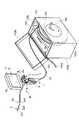
また、図18は本発明の第7の実施の形態を示すものである。本実施の形態は第1の実施の形態(図1(A),(B)乃至図9参照)の工業用内視鏡装置1の内視鏡収納ケース102の構成を次の通り変更したものである。
【0054】
すなわち、本実施の形態の内視鏡収納ケース102では第2の収納室103b内に巻き取りドラム105が配設されている。内視鏡収納ケース102のフロントパネル102cには巻き取りドラム105の取っ手106が配設されている。
【0055】
そこで、上記構成の本実施の形態では、取っ手106を図18中で矢印方向に回転操作することにより、巻き取りドラム105にスコープ部2の挿入部2aと、ユニバーサルコード2cとを操作部2bごと巻き取ることができる。そのため、使用後のスコープ部2の収納操作を簡単に行なうことができる効果がある。
【0056】
さらに、本発明は上記実施の形態に限定されるものではなく、本発明の要旨を逸脱しない範囲で種々変形実施できることは勿論である。
次に、本出願の他の特徴的な技術事項を下記の通り付記する。
記
(付記項1) 挿入部基端側に配置され、少なくとも片手で把持し、湾曲操作を行なう湾曲操作入力手段と把持部を有する操作部と、
前記挿入部内に配置され、前記挿入部先端側に一端が開口し、他端が前記挿入部の基端側に開口する処置具挿通路とを有する内視鏡において、
把持部に前記処置具挿通路の基端側開口部を設けたことを特徴とする内視鏡装置。
【0057】
(付記項2) 付記項1の把持部に連続して、枠体により設置された内視鏡の観察像を表示する表示手段を有し、前記把持部および枠体に前記開口部を設けたことを特徴とする内視鏡装置。
【0058】
(付記項1、2の従来技術) 挿入部内に鉗子挿通チャンネルを有し、挿入部基端側に電動湾曲操作部を有する内視鏡がある。
【0059】
【発明の効果】
請求項1の発明によれば、挿入部の先端側に開口する先端側開口端と挿入部の基端側に開口する基端側開口端との間を連通する処置具挿通路を挿入部に設け、操作部の把持部に処置具挿通路の基端側開口端を設けたので、電動湾曲操作式の湾曲入力手段の操作による湾曲部の湾曲操作と、処置具などの操作の両方を簡単に行なうことができ、操作性の良い内視鏡装置を提供することができる。
【0060】
請求項2の発明によれば、把持部の表示手段によって内視鏡の観察像を表示することができる。
【0061】
請求項3の発明によれば、表示手段の表示パネルを支持する枠体の処置具挿通路の基端側開口端で処置具などの操作を行なうことができる。
【0062】
請求項4の発明によれば、把持部の裏面の処置具挿通路の基端側開口端で処置具などの操作を行なうことができる。
【図面の簡単な説明】
【図1】本発明の第1の実施の形態を示すもので、(A)は工業用内視鏡装置全体の概略構成を示す斜視図、(B)は工業用内視鏡のヘッド部の先端面を示す平面図。
【図2】第1の実施の形態の工業用内視鏡装置における操作部の外観を示す斜視図。
【図3】第1の実施の形態の工業用内視鏡装置における操作部の一部を断面にして示す側面図。
【図4】第1の実施の形態の工業用内視鏡装置における操作部のグリップ部を使用者の片手によって把持する状態の第1の例を示す斜視図。
【図5】第1の実施の形態の工業用内視鏡装置における操作部のグリップ部を使用者の片手によって把持する状態の第2の例を示す斜視図。
【図6】第1の実施の形態の工業用内視鏡装置における操作部のグリップ部の下部を使用者の片手によって把持する状態を示す斜視図。
【図7】第1の実施の形態の工業用内視鏡装置における操作部のグリップ部を使用者の両手によって把持する状態を示す斜視図。
【図8】第1の実施の形態の工業用内視鏡装置における内視鏡検査時の状態を示す斜視図。
【図9】第1の実施の形態の工業用内視鏡装置における内視鏡検査時に鉗子などの処置具を使用している状態を示す斜視図。
【図10】本発明の第2の実施の形態の工業用内視鏡装置における操作部の外観を示す斜視図。
【図11】第2の実施の形態の工業用内視鏡装置における操作部の一部を断面にして示す側面図。
【図12】本発明の第3の実施の形態の工業用内視鏡装置における操作部の一部を断面にして示す側面図。
【図13】本発明の第4の実施の形態の工業用内視鏡装置における操作部の外観を示す斜視図。
【図14】第4の実施の形態の工業用内視鏡装置における操作部の一部を断面にして示す側面図。
【図15】本発明の第5の実施の形態の工業用内視鏡装置における操作部の外観を示す斜視図。
【図16】第5の実施の形態の工業用内視鏡装置における操作部の一部を断面にして示す側面図。
【図17】本発明の第6の実施の形態の工業用内視鏡装置における操作部の外観を示す斜視図。
【図18】本発明の第7の実施の形態の工業用内視鏡装置全体の外観を示す斜視図。
【符号の説明】
2 スコープ部
2a 挿入部
2a2 湾曲部
5 内部チャンネル(処置具挿通路)
6 先端側開口端
7 グリップ部(把持部)
8 ジョイスティック(湾曲操作手段)
10 モニター部(表示手段)
11 鉗子口(基端側開口端)[0001]
TECHNICAL FIELD OF THE INVENTION
The present invention relates to an endoscope apparatus mainly used in the industrial field, which is inserted into an inspection space such as a pipe and observes the inspection space.
[0002]
[Prior art]
In general, industrial endoscopes often have a configuration in which a proximal operation portion is connected to a base end of an elongated insertion portion that is inserted into a test space such as a pipe. Here, a head unit in which an observation optical system for observation, an illumination optical system, and the like are incorporated is provided on the most distal end side of the insertion unit. Further, a bending portion that can be bent in an up-down direction, a left-right direction, or any combination of these directions is provided behind the head portion. The distal end portions of a plurality of, for example, four bending operation wires are fixed to the bending portion. The proximal end of each bending operation wire extends to the proximal side and is connected to a bending operation mechanism provided in the operation unit on the proximal side.
[0003]
Further, an operation knob for driving the bending operation mechanism and performing a bending operation on the bending portion is provided in the operation unit on the hand side. Then, the bending operation mechanism is driven based on the turning operation of the operation knob, the bending operation wire is pulled, and the bending portion is operated in accordance with the turning operation of the operation knob in conjunction with the pulling operation of each bending operation wire. Bending operation is performed.
[0004]
The insertion section of the endoscope is provided with an internal channel (treatment instrument insertion passage) for inserting treatment tools such as forceps. The head portion of the insertion portion is formed with an opening end on the distal end side of the internal channel. Further, a forceps port (a base end side open end) of the internal channel is provided in the operation unit.
[0005]
In addition, in recent years, the bending mechanism has been electrified, and the bending input means is also operated by a manual operation knob, for example, an electric bending operation type such as a joystick that emits a signal corresponding to the tilt angle as shown in Patent Document 1. In some cases. In this case, the operation input means such as the joystick need not always be fixed to the operation section on the rear end side of the insertion section.
[0006]
Therefore, it has been considered that a bending input unit such as a joystick is provided independently of the operation unit on the rear end side of the insertion unit separately from the operation unit. In this case, if you want to perform only the bending operation when using the endoscope device, operate only the bending input device such as a joystick at a place different from the operation unit, and hold the insertion unit at an arbitrary position. Good. When only the forceps operation is to be performed, the forceps may be operated at the forceps port or in the vicinity thereof while holding the operation unit.
[0007]
[Patent Document 1]
US Patent No. 5,373,317
[Problems to be solved by the invention]
However, when an electric bending operation-type bending input means such as a joystick is disposed at a place different from the operation section, the bending operation of the bending section by the operation of the bending input means such as the joystick and the forceps operation from the forceps port are performed. If you want to do both, you need to do that separately in another place. Therefore, there is a problem that the operation is difficult to perform as compared with the endoscope of the conventional configuration in which the operation knob and the forceps port of the internal channel are arranged in the operation unit.
[0009]
The present invention has been made in view of the above circumstances, and an object of the present invention is to easily perform both a bending operation of a bending portion by operating a bending input unit of an electric bending operation type and an operation of a treatment tool. To provide an endoscope apparatus with good operability.
[0010]
[Means for Solving the Problems]
According to the first aspect of the present invention, the bending portion is provided in the flexible elongated insertion portion inserted into the inspection target space,
In an endoscope apparatus, an operation unit including a bending operation unit and a grip unit for performing a bending operation on the bending unit is disposed on a base end side of the insertion unit.
A treatment tool insertion passage communicating between a distal open end that opens to the distal end of the insertion portion and a proximal open end that opens to the proximal end of the insertion portion is provided in the insertion portion,
An endoscope apparatus characterized in that a base end side opening end of the treatment instrument insertion passage is provided in a grip portion of the operation portion.
[0011]
According to the first aspect of the present invention, the bending section is operated to bend by the bending operation means of the operation section, and the treatment tool or the like is operated at the base end side opening end of the treatment tool insertion passage of the grasping section in the vicinity thereof. It is something that can be done.
[0012]
The invention according to
[0013]
According to the second aspect of the present invention, the observation image of the endoscope is displayed by the display means of the grip portion.
[0014]
According to a third aspect of the present invention, the display means includes a display panel and a frame supporting the display panel.
The endoscope apparatus according to
[0015]
According to the third aspect of the present invention, the operation of the treatment tool or the like can be performed at the base end side opening end of the treatment tool insertion passage of the frame supporting the display panel of the display means.
[0016]
The invention according to claim 4 is the endoscope apparatus according to claim 1, wherein a proximal open end of the treatment tool insertion passage is disposed on a back surface of the grip portion.
[0017]
According to the fourth aspect of the present invention, the operation of the treatment tool or the like can be performed at the base end side open end of the treatment tool insertion passage on the back surface of the grip portion.
[0018]
BEST MODE FOR CARRYING OUT THE INVENTION
Hereinafter, a first embodiment of the present invention will be described with reference to FIGS. FIG. 1A shows an industrial endoscope apparatus 1 according to the present embodiment. The endoscope apparatus 1 is provided with an endoscope apparatus
[0019]
Further, the
[0020]
Further, as shown in FIG. 1B, an
[0021]
The distal end of the
[0022]
Here, the
[0023]
Further, a monitor section (display means) 10 and a forceps port (opening end on the proximal side) 11 of the
[0024]
The
[0025]
Further, a tubular forceps
[0026]
The lower end of the
[0027]
A
[0028]
The fixed
[0029]
The image data of the endoscope observation image captured by the CCD is converted into an electric signal and transmitted to the camera control unit via an electric code. At this time, after being converted into a video signal by the camera control unit, an output signal from the camera control unit is input to the
[0030]
Further, the drive motor of the bending drive mechanism of the bending section 2a2 of the
[0031]
Further, the
[0032]
Further, the inside of the
[0033]
Next, the operation of the above configuration will be described. When the industrial endoscope apparatus 1 according to the present embodiment is used, the
[0034]
At the time of an endoscope inspection, as shown in FIG. 8, image data of an endoscope observation image picked up by a CCD of an observation optical system of a head unit 2a1 is converted into an electric signal, and is converted into a camera control unit via an electric cord. Transmitted to At this time, after being converted into a video signal by the camera control unit, an output signal from the camera control unit is input to the
[0035]
Further, during the endoscopic inspection, the
[0036]
When using a
[0037]
Therefore, the above configuration has the following effects. That is, in the industrial endoscope apparatus 1 of the present embodiment, the
[0038]
FIGS. 10 and 11 show a second embodiment of the present invention. In the present embodiment, the configuration of the
[0039]
That is, in the
[0040]
Therefore, in the
[0041]
FIG. 12 shows a third embodiment of the present invention. In the present embodiment, the configuration of the
[0042]
That is, in the
[0043]
Therefore, in the
[0044]
FIGS. 13 and 14 show a fourth embodiment of the present invention. In the present embodiment, the configuration of the
[0045]
That is, the
[0046]
Therefore, in the
[0047]
FIGS. 15 and 16 show a fifth embodiment of the present invention. In the present embodiment, the configuration of the
[0048]
That is, in the
[0049]
Therefore, in the
[0050]
FIG. 17 shows a sixth embodiment of the present invention. In the present embodiment, the configuration of the
[0051]
That is, in the
[0052]
Therefore, in the present embodiment having the above configuration, the
[0053]
FIG. 18 shows a seventh embodiment of the present invention. In the present embodiment, the configuration of the
[0054]
That is, in the
[0055]
Therefore, in the present embodiment having the above configuration, the
[0056]
Furthermore, the present invention is not limited to the above-described embodiment, and it goes without saying that various modifications can be made without departing from the spirit of the present invention.
Next, other characteristic technical matters of the present application will be additionally described as follows.
(Additional Item 1) An operation unit that is disposed on the proximal end side of the insertion unit, has a bending operation input unit that grips with at least one hand and performs a bending operation, and an operation unit that has a grip unit.
An endoscope having a treatment tool insertion passage disposed in the insertion portion, one end of which is open on the distal end side of the insert portion, and the other end of which is open on the proximal end side of the insert portion.
An endoscope apparatus wherein a base end side opening of the treatment instrument insertion passage is provided in a grip portion.
[0057]
(Additional Item 2) A display means for displaying an observation image of an endoscope provided by a frame body is provided continuously with the grip portion of Additional Item 1, and the opening is provided in the grip portion and the frame body. An endoscope apparatus characterized by the above-mentioned.
[0058]
There is an endoscope having a forceps insertion channel in an insertion portion and an electric bending operation portion on a proximal end side of the insertion portion.
[0059]
【The invention's effect】
According to the first aspect of the present invention, the treatment tool insertion passage communicating between the distal end opening end opening to the distal end side of the insertion portion and the proximal opening end opening to the proximal end side of the insertion portion is provided in the insertion portion. Since the base end side opening end of the treatment instrument insertion passage is provided in the grip portion of the operation section, both the bending operation of the bending section by the operation of the electric bending operation type bending input means and the operation of the treatment instrument and the like are simplified. And an endoscope device with good operability can be provided.
[0060]
According to the second aspect of the present invention, the observation image of the endoscope can be displayed by the display means of the grip portion.
[0061]
According to the third aspect of the present invention, the operation of the treatment tool or the like can be performed at the base end side open end of the treatment tool insertion passage of the frame supporting the display panel of the display means.
[0062]
According to the fourth aspect of the present invention, the operation of the treatment tool or the like can be performed at the base end side opening end of the treatment tool insertion passage on the back surface of the grip portion.
[Brief description of the drawings]
1A and 1B show a first embodiment of the present invention, in which FIG. 1A is a perspective view showing a schematic configuration of an entire industrial endoscope apparatus, and FIG. 1B is a perspective view of a head section of the industrial endoscope. FIG. 3 is a plan view showing a tip surface.
FIG. 2 is a perspective view showing an appearance of an operation unit in the industrial endoscope device according to the first embodiment.
FIG. 3 is a side view showing a part of the operation unit in the industrial endoscope apparatus according to the first embodiment in cross section;
FIG. 4 is a perspective view showing a first example of a state in which the grip portion of the operation unit in the industrial endoscope device according to the first embodiment is gripped by one hand of a user.
FIG. 5 is a perspective view showing a second example of a state in which the grip section of the operation section in the industrial endoscope apparatus according to the first embodiment is gripped by one hand of a user.
FIG. 6 is an exemplary perspective view showing a state in which the lower part of the grip portion of the operation unit in the industrial endoscope device according to the first embodiment is gripped by one hand of a user;
FIG. 7 is an exemplary perspective view showing a state in which the grip section of the operation section in the industrial endoscope apparatus according to the first embodiment is gripped by both hands of a user;
FIG. 8 is a perspective view showing a state of the industrial endoscope apparatus according to the first embodiment at the time of endoscopic inspection.
FIG. 9 is a perspective view showing a state in which a treatment tool such as forceps is used at the time of endoscopic inspection in the industrial endoscope apparatus according to the first embodiment.
FIG. 10 is a perspective view showing the appearance of an operation unit in an industrial endoscope apparatus according to a second embodiment of the present invention.
FIG. 11 is a side view showing a cross section of a part of an operation unit in the industrial endoscope apparatus according to the second embodiment.
FIG. 12 is a side view showing a cross section of a part of an operation unit in an industrial endoscope apparatus according to a third embodiment of the present invention.
FIG. 13 is a perspective view showing the appearance of an operation unit in an industrial endoscope apparatus according to a fourth embodiment of the present invention.
FIG. 14 is a side view showing a cross section of a part of the operation unit in the industrial endoscope apparatus according to the fourth embodiment;
FIG. 15 is a perspective view showing the appearance of an operation unit in an industrial endoscope apparatus according to a fifth embodiment of the present invention.
FIG. 16 is a side view showing, in section, a part of the operation unit in the industrial endoscope apparatus according to the fifth embodiment.
FIG. 17 is a perspective view showing the appearance of an operation unit in an industrial endoscope apparatus according to a sixth embodiment of the present invention.
FIG. 18 is a perspective view showing the appearance of an entire industrial endoscope apparatus according to a seventh embodiment of the present invention.
[Explanation of symbols]
2
6 Tip side
8 Joystick (bending operation means)
10. Monitor part (display means)
11 Forceps port (proximal open end)
Claims (4)
Translated fromJapanese前記湾曲部を湾曲操作するための湾曲操作手段と把持部とを備えた操作部が前記挿入部の基端側に配置された内視鏡装置において、
前記挿入部の先端側に開口する先端側開口端と前記挿入部の基端側に開口する基端側開口端との間を連通する処置具挿通路を前記挿入部に設け、
前記操作部の把持部に前記処置具挿通路の基端側開口端を設けたことを特徴とする内視鏡装置。A curved portion is arranged in a flexible elongated insertion portion inserted into the inspection target space,
In an endoscope apparatus, an operation unit including a bending operation unit and a grip unit for performing a bending operation on the bending unit is disposed on a base end side of the insertion unit.
A treatment tool insertion passage communicating between a distal open end that opens to the distal end of the insertion portion and a proximal open end that opens to the proximal end of the insertion portion is provided in the insertion portion,
An endoscope apparatus wherein a base end side opening end of the treatment instrument insertion passage is provided in a grip portion of the operation unit.
前記処置具挿通路の基端側開口端は、前記枠体に配置されていることを特徴とする請求項2に記載の内視鏡装置。The display means includes a display panel, and a frame supporting the display panel,
The endoscope apparatus according to claim 2, wherein a proximal open end of the treatment instrument insertion passage is disposed in the frame.
Priority Applications (2)
| Application Number | Priority Date | Filing Date | Title |
|---|---|---|---|
| JP2002268729AJP2004109222A (en) | 2002-09-13 | 2002-09-13 | Endoscope apparatus |
| US10/658,381US7214183B2 (en) | 2002-09-13 | 2003-09-10 | Endoscope apparatus having an insertion channel |
Applications Claiming Priority (1)
| Application Number | Priority Date | Filing Date | Title |
|---|---|---|---|
| JP2002268729AJP2004109222A (en) | 2002-09-13 | 2002-09-13 | Endoscope apparatus |
Related Child Applications (1)
| Application Number | Title | Priority Date | Filing Date |
|---|---|---|---|
| JP2005232546ADivisionJP4451363B2 (en) | 2005-08-10 | 2005-08-10 | Endoscope device |
Publications (2)
| Publication Number | Publication Date |
|---|---|
| JP2004109222Atrue JP2004109222A (en) | 2004-04-08 |
| JP2004109222A5 JP2004109222A5 (en) | 2005-10-27 |
Family
ID=31986786
Family Applications (1)
| Application Number | Title | Priority Date | Filing Date |
|---|---|---|---|
| JP2002268729APendingJP2004109222A (en) | 2002-09-13 | 2002-09-13 | Endoscope apparatus |
Country Status (2)
| Country | Link |
|---|---|
| US (1) | US7214183B2 (en) |
| JP (1) | JP2004109222A (en) |
Cited By (20)
| Publication number | Priority date | Publication date | Assignee | Title |
|---|---|---|---|---|
| JP2006068453A (en)* | 2004-09-06 | 2006-03-16 | Olympus Corp | Endoscope device equipped with drum mechanism |
| JP2006149881A (en)* | 2004-11-30 | 2006-06-15 | Olympus Medical Systems Corp | Endoscope |
| JP2006204582A (en)* | 2005-01-28 | 2006-08-10 | Olympus Corp | Endoscope apparatus |
| JP2007252925A (en)* | 2006-03-23 | 2007-10-04 | Ethicon Endo Surgery Inc | Disposable endoscope device |
| JP2009006118A (en)* | 2007-05-28 | 2009-01-15 | Olympus Corp | Endoscope apparatus |
| JP2009508636A (en)* | 2005-09-20 | 2009-03-05 | エイアイ メディカル デバイセズ、インコーポレイテッド | Endotracheal intubation device |
| JP2011019908A (en)* | 2009-07-15 | 2011-02-03 | Medical Intubation Technology Corp | Endoscope device and endoscope device image processing method |
| JP2011062250A (en)* | 2009-09-15 | 2011-03-31 | Olympus Corp | Endoscope apparatus |
| JP2011069883A (en)* | 2009-09-24 | 2011-04-07 | Olympus Corp | Endoscope device |
| JP2011189119A (en)* | 2010-03-12 | 2011-09-29 | Microline Surgical Inc | Picture in picture clip applier video system |
| JP4896272B1 (en)* | 2010-12-24 | 2012-03-14 | オリンパス株式会社 | Endoscope device |
| JP4897117B1 (en)* | 2010-12-24 | 2012-03-14 | オリンパス株式会社 | Endoscope device |
| JP4896273B1 (en)* | 2010-12-24 | 2012-03-14 | オリンパス株式会社 | Endoscope device |
| JP4897116B1 (en)* | 2010-12-24 | 2012-03-14 | オリンパス株式会社 | Endoscope device |
| US8177710B1 (en) | 2011-08-02 | 2012-05-15 | Olympus Corporation | Endoscopic device |
| US8182416B1 (en) | 2011-08-02 | 2012-05-22 | Olympus Corporation | Endoscopic device |
| JP5006478B2 (en)* | 2010-08-05 | 2012-08-22 | オリンパスメディカルシステムズ株式会社 | Endoscope |
| JPWO2013069699A1 (en)* | 2011-11-07 | 2015-04-02 | 株式会社フジクラ | Suction catheter |
| WO2018230131A1 (en)* | 2017-06-15 | 2018-12-20 | オリンパス株式会社 | Endoscope |
| WO2022218323A1 (en)* | 2021-04-16 | 2022-10-20 | 深圳市显文数码科技有限公司 | Omnidirectional endoscope mechanism |
Families Citing this family (73)
| Publication number | Priority date | Publication date | Assignee | Title |
|---|---|---|---|---|
| US20040199052A1 (en) | 2003-04-01 | 2004-10-07 | Scimed Life Systems, Inc. | Endoscopic imaging system |
| US8517921B2 (en)* | 2004-04-16 | 2013-08-27 | Gyrus Acmi, Inc. | Endoscopic instrument having reduced diameter flexible shaft |
| JP4091016B2 (en)* | 2004-04-22 | 2008-05-28 | オリンパス株式会社 | Endoscope system |
| US8251891B2 (en)* | 2004-05-14 | 2012-08-28 | Nathan Moskowitz | Totally wireless electronically embedded action-ended endoscope utilizing differential directional illumination with digitally controlled mirrors and/or prisms |
| JP2008514363A (en)* | 2004-09-30 | 2008-05-08 | ボストン サイエンティフィック リミテッド | Multifunctional endoscope system for use in electrosurgical applications |
| US7584534B2 (en)* | 2005-01-10 | 2009-09-08 | Perceptron, Inc. | Remote inspection device |
| US20060155168A1 (en)* | 2005-01-10 | 2006-07-13 | Pease Alfred A | Optical snake |
| US7384308B2 (en)* | 2005-01-10 | 2008-06-10 | Perceptron, Inc. | Detachable coupling for a remote inspection device |
| WO2006086106A2 (en)* | 2005-01-10 | 2006-08-17 | Perceptron, Inc. | Optical snake |
| US20070185379A1 (en)* | 2005-01-10 | 2007-08-09 | Perceptron, Inc. | Modular remote inspection device with digital imager |
| WO2007002526A1 (en)* | 2005-06-24 | 2007-01-04 | Everest Vit, Inc. | Insertion tube storage carousel |
| USD618794S1 (en)* | 2005-10-25 | 2010-06-29 | Pentax Corporation | Video laryngoscope |
| USD611142S1 (en)* | 2008-08-01 | 2010-03-02 | Envisionier Medical Technologies, Inc. | Holder for a removable camera screen |
| US20100145146A1 (en)* | 2005-12-28 | 2010-06-10 | Envisionier Medical Technologies, Inc. | Endoscopic digital recording system with removable screen and storage device |
| US7581988B2 (en)* | 2006-06-30 | 2009-09-01 | Perceptron, Inc. | Detachable coupling for a remote inspection device |
| USD581051S1 (en)* | 2006-06-30 | 2008-11-18 | Envisionier Medical Technologies Llc | Camera |
| JP2008011992A (en)* | 2006-07-04 | 2008-01-24 | Olympus Medical Systems Corp | Endoscope |
| US20100286477A1 (en)* | 2009-05-08 | 2010-11-11 | Ouyang Xiaolong | Internal tissue visualization system comprising a rf-shielded visualization sensor module |
| FR2907918B1 (en)* | 2006-10-31 | 2009-01-23 | Tokendo Soc Par Actions Simpli | VIDEO PROBEENDOSCOPY WITH INTEGRATED IMAGE STORAGE DEVICE |
| US20080269556A1 (en)* | 2007-04-02 | 2008-10-30 | Jagasia Ashok A | Endoscope with flexible tip |
| DE102008018931A1 (en) | 2007-04-17 | 2008-11-13 | Gyrus ACMI, Inc., Southborough | Light source power based on a predetermined detected condition |
| US20080262293A1 (en)* | 2007-04-19 | 2008-10-23 | Olympus Medical Systems Corp | Endoscopic operation assisting device |
| CA2625548C (en) | 2007-08-04 | 2012-04-10 | John A. Law | An airway intubation device |
| CA2717860C (en) | 2008-03-07 | 2016-11-08 | Milwaukee Electric Tool Corporation | Battery pack for use with a power tool and a non-motorized sensing tool |
| GB2470327B (en)* | 2008-03-07 | 2012-03-21 | Milwaukee Electric Tool Corp | Visual inspection device |
| US20100022824A1 (en) | 2008-07-22 | 2010-01-28 | Cybulski James S | Tissue modification devices and methods of using the same |
| US20110009694A1 (en)* | 2009-07-10 | 2011-01-13 | Schultz Eric E | Hand-held minimally dimensioned diagnostic device having integrated distal end visualization |
| US20100121139A1 (en) | 2008-11-12 | 2010-05-13 | Ouyang Xiaolong | Minimally Invasive Imaging Systems |
| JP5500844B2 (en)* | 2009-03-18 | 2014-05-21 | 富士フイルム株式会社 | Endoscope |
| JP5052553B2 (en)* | 2009-03-19 | 2012-10-17 | オリンパス株式会社 | Treatment endoscope |
| WO2011013453A1 (en)* | 2009-07-29 | 2011-02-03 | オリンパスメディカルシステムズ株式会社 | Endoscope device |
| US20110028785A1 (en)* | 2009-07-31 | 2011-02-03 | There In One Enterprises Co., Ltd. | Endoscope with adjustable viewing angle |
| US8512232B2 (en) | 2009-09-08 | 2013-08-20 | Gyrus Acmi, Inc. | Endoscopic illumination system, assembly and methods for staged illumination of different target areas |
| TWM394136U (en)* | 2009-12-24 | 2010-12-11 | Tien-Sheng Chen | Probe with image-capturing device |
| US9049351B2 (en) | 2010-05-03 | 2015-06-02 | Inspectron, Inc. | Insulator design for video inspection devices |
| CN203550906U (en) | 2011-02-16 | 2014-04-16 | 米沃奇电动工具公司 | Visual inspection equipment |
| HK1198738A1 (en)* | 2011-05-03 | 2015-06-05 | Endosee股份有限公司 | Method and apparatus for hysteroscopy and endometrial biopsy |
| USD671214S1 (en)* | 2011-08-08 | 2012-11-20 | Olympus Corporation | Endoscope |
| USD671213S1 (en)* | 2011-08-08 | 2012-11-20 | Olympus Corporation | Endoscope |
| USD659840S1 (en)* | 2011-09-16 | 2012-05-15 | Medimaging Integrated Solution, Inc. | Digital diagnostic device |
| WO2013106444A1 (en)* | 2012-01-10 | 2013-07-18 | Boston Scientific Scimed, Inc. | A steerable medical device having an imaging system |
| US8556801B2 (en)* | 2012-02-23 | 2013-10-15 | Jung-Tung Liu | Combined endoscope and surgical instrument guide device |
| CN104219987B (en)* | 2012-03-23 | 2016-10-26 | 奥林巴斯株式会社 | Insertion apparatus |
| US9468367B2 (en) | 2012-05-14 | 2016-10-18 | Endosee Corporation | Method and apparatus for hysteroscopy and combined hysteroscopy and endometrial biopsy |
| US9622646B2 (en) | 2012-06-25 | 2017-04-18 | Coopersurgical, Inc. | Low-cost instrument for endoscopically guided operative procedures |
| USD714167S1 (en)* | 2012-09-04 | 2014-09-30 | S.P.M. Instrument Ab | Control device |
| US9736342B2 (en)* | 2012-10-19 | 2017-08-15 | Milwaukee Electric Tool Corporation | Visual inspection device |
| US9186049B2 (en)* | 2012-10-25 | 2015-11-17 | Choon Kee Lee | Extensible and guidable apparatus |
| US9168099B2 (en)* | 2012-10-25 | 2015-10-27 | Gyrus Acmi, Inc. | Lithotripsy apparatus using a flexible endoscope |
| USD723684S1 (en)* | 2013-02-20 | 2015-03-03 | Olympus Corporation | Industrial endoscope |
| DE102013207109A1 (en)* | 2013-04-19 | 2014-11-06 | Henke-Sass, Wolf Gmbh | Endoscope with a rigid curved shaft and method for producing such an endoscope |
| JP6245877B2 (en) | 2013-07-26 | 2017-12-13 | オリンパス株式会社 | Operation input device for endoscope treatment tool |
| US9370295B2 (en) | 2014-01-13 | 2016-06-21 | Trice Medical, Inc. | Fully integrated, disposable tissue visualization device |
| US11547446B2 (en) | 2014-01-13 | 2023-01-10 | Trice Medical, Inc. | Fully integrated, disposable tissue visualization device |
| US10342579B2 (en) | 2014-01-13 | 2019-07-09 | Trice Medical, Inc. | Fully integrated, disposable tissue visualization device |
| JP6717752B2 (en) | 2014-04-04 | 2020-07-01 | ボストン サイエンティフィック サイムド,インコーポレイテッドBoston Scientific Scimed,Inc. | Medical devices for diagnosis and treatment |
| WO2016137838A1 (en)* | 2015-02-23 | 2016-09-01 | Xiaolong Ouyang | Handheld surgical endoscope |
| US10869592B2 (en) | 2015-02-23 | 2020-12-22 | Uroviu Corp. | Handheld surgical endoscope |
| WO2017027749A1 (en) | 2015-08-11 | 2017-02-16 | Trice Medical, Inc. | Fully integrated, disposable tissue visualization device |
| WO2017030036A1 (en)* | 2015-08-18 | 2017-02-23 | オリンパス株式会社 | Endoscope |
| US10702305B2 (en) | 2016-03-23 | 2020-07-07 | Coopersurgical, Inc. | Operative cannulas and related methods |
| US10245112B2 (en)* | 2016-06-27 | 2019-04-02 | Corindus, Inc. | Interlocking system and method for joysticks in a catheter procedure system |
| US11832797B2 (en) | 2016-09-25 | 2023-12-05 | Micronvision Corp. | Endoscopic fluorescence imaging |
| US11684248B2 (en) | 2017-09-25 | 2023-06-27 | Micronvision Corp. | Endoscopy/stereo colposcopy medical instrument |
| US11445890B2 (en)* | 2017-08-17 | 2022-09-20 | David M Schreck | Modular endoscope |
| US20230172433A1 (en)* | 2017-08-17 | 2023-06-08 | Marc A. Levinson | Modular endoscope with a bayonet connection |
| US11771304B1 (en) | 2020-11-12 | 2023-10-03 | Micronvision Corp. | Minimally invasive endoscope |
| US11980342B2 (en) | 2020-11-12 | 2024-05-14 | Micronvision Corp. | Minimally invasive endoscope |
| US12268358B2 (en) | 2019-12-05 | 2025-04-08 | Uroviu Corp. | Portable endoscope with side-mountable disposable portion |
| EP3773235B1 (en) | 2018-03-29 | 2023-07-19 | Trice Medical, Inc. | Fully integrated endoscope with biopsy capabilities |
| WO2020039498A1 (en)* | 2018-08-21 | 2020-02-27 | オリンパス株式会社 | Endoscope |
| EP4003138A4 (en) | 2019-07-25 | 2023-08-30 | Uroviu Corp. | DISPOSABLE ENDOSCOPY NEEDLE WITH INTEGRATED GRIPPER |
| WO2024129771A1 (en)* | 2022-12-12 | 2024-06-20 | Vanderbilt University | Controller with a touchpad user interface for operating robotically actuated devices |
Family Cites Families (30)
| Publication number | Priority date | Publication date | Assignee | Title |
|---|---|---|---|---|
| US3897775A (en)* | 1973-09-07 | 1975-08-05 | Olympus Optical Co | Endoscope with facile bending operation |
| US4598698A (en)* | 1983-01-20 | 1986-07-08 | Warner-Lambert Technologies, Inc. | Diagnostic device |
| JPS60137342A (en)* | 1983-12-27 | 1985-07-20 | オリンパス光学工業株式会社 | Electronic scope |
| DE3569876D1 (en)* | 1984-02-20 | 1989-06-08 | Olympus Optical Co | Endoscopic ovum picker instruments |
| JPS6233801U (en)* | 1985-08-14 | 1987-02-27 | ||
| US4649904A (en)* | 1986-01-02 | 1987-03-17 | Welch Allyn, Inc. | Biopsy seal |
| JPS6335226A (en) | 1986-07-30 | 1988-02-15 | オリンパス光学工業株式会社 | Endoscope |
| US4905082A (en)* | 1987-05-06 | 1990-02-27 | Olympus Optical Co., Ltd. | Rigid video endoscope having a detachable imaging unit |
| CH672255A5 (en)* | 1987-06-29 | 1989-11-15 | Renaud Croisy | |
| US4874364A (en)* | 1988-03-22 | 1989-10-17 | Circon Corporation | Inspection instrument channel aspirator and pressure neutralizing device |
| US4934340A (en)* | 1989-06-08 | 1990-06-19 | Hemo Laser Corporation | Device for guiding medical catheters and scopes |
| US5531664A (en)* | 1990-12-26 | 1996-07-02 | Olympus Optical Co., Ltd. | Bending actuator having a coil sheath with a fixed distal end and a free proximal end |
| US5183031A (en)* | 1991-05-13 | 1993-02-02 | Rossoff Leonard J | Fiberoptic intubating laryngoscope |
| US5658238A (en)* | 1992-02-25 | 1997-08-19 | Olympus Optical Co., Ltd. | Endoscope apparatus capable of being switched to a mode in which a curvature operating lever is returned and to a mode in which the curvature operating lever is not returned |
| JP3421038B2 (en)* | 1992-09-01 | 2003-06-30 | エドウィン エル アデアー, | Sterilizable endoscope having a detachable disposable tube assembly |
| EP0587514A1 (en)* | 1992-09-11 | 1994-03-16 | Welch Allyn, Inc. | Processor module for video inspection probe |
| US5314070A (en)* | 1992-12-16 | 1994-05-24 | Welch Allyn, Inc. | Case for flexible borescope and endoscope insertion tubes |
| US5373317B1 (en) | 1993-05-28 | 2000-11-21 | Welch Allyn Inc | Control and display section for borescope or endoscope |
| US5964740A (en)* | 1996-07-09 | 1999-10-12 | Asahi Kogaku Kogyo Kabushiki Kaisha | Treatment accessory for an endoscope |
| US6221007B1 (en)* | 1996-05-03 | 2001-04-24 | Philip S. Green | System and method for endoscopic imaging and endosurgery |
| US5928137A (en)* | 1996-05-03 | 1999-07-27 | Green; Philip S. | System and method for endoscopic imaging and endosurgery |
| US5873814A (en)* | 1996-07-12 | 1999-02-23 | Adair; Edwin L. | Sterile encapsulated endoscopic video monitor and method |
| US5785644A (en)* | 1996-07-12 | 1998-07-28 | Circon Corporation | Pivotal handle assembly for a video operating laparoscope |
| US6554765B1 (en)* | 1996-07-15 | 2003-04-29 | East Giant Limited | Hand held, portable camera with adaptable lens system |
| US5971917A (en)* | 1997-02-26 | 1999-10-26 | Fuji Photo Optical Co., Ltd. | Endoscope having washing ports |
| FR2785132B1 (en)* | 1998-10-27 | 2000-12-22 | Tokendo Sarl | DISTAL COLOR CCD SENSOR VIDEOENDOSCOPIC PROBE |
| US6652453B2 (en)* | 1999-03-03 | 2003-11-25 | Vincent A. Smith | Portable video laryngoscope |
| US6569084B1 (en)* | 1999-03-31 | 2003-05-27 | Olympus Optical Co., Ltd. | Endoscope holder and endoscope device |
| US6858005B2 (en)* | 2000-04-03 | 2005-02-22 | Neo Guide Systems, Inc. | Tendon-driven endoscope and methods of insertion |
| US7261728B2 (en)* | 2002-03-15 | 2007-08-28 | Ethicon Endo-Surgery, Inc. | Biopsy forceps device and method |
- 2002
- 2002-09-13JPJP2002268729Apatent/JP2004109222A/enactivePending
- 2003
- 2003-09-10USUS10/658,381patent/US7214183B2/ennot_activeExpired - Fee Related
Cited By (36)
| Publication number | Priority date | Publication date | Assignee | Title |
|---|---|---|---|---|
| JP2006068453A (en)* | 2004-09-06 | 2006-03-16 | Olympus Corp | Endoscope device equipped with drum mechanism |
| JP2006149881A (en)* | 2004-11-30 | 2006-06-15 | Olympus Medical Systems Corp | Endoscope |
| JP2006204582A (en)* | 2005-01-28 | 2006-08-10 | Olympus Corp | Endoscope apparatus |
| JP2009508636A (en)* | 2005-09-20 | 2009-03-05 | エイアイ メディカル デバイセズ、インコーポレイテッド | Endotracheal intubation device |
| JP2007252925A (en)* | 2006-03-23 | 2007-10-04 | Ethicon Endo Surgery Inc | Disposable endoscope device |
| JP2009006118A (en)* | 2007-05-28 | 2009-01-15 | Olympus Corp | Endoscope apparatus |
| JP2011019908A (en)* | 2009-07-15 | 2011-02-03 | Medical Intubation Technology Corp | Endoscope device and endoscope device image processing method |
| JP2011062250A (en)* | 2009-09-15 | 2011-03-31 | Olympus Corp | Endoscope apparatus |
| JP2011069883A (en)* | 2009-09-24 | 2011-04-07 | Olympus Corp | Endoscope device |
| JP2011189119A (en)* | 2010-03-12 | 2011-09-29 | Microline Surgical Inc | Picture in picture clip applier video system |
| US8920309B2 (en) | 2010-03-12 | 2014-12-30 | Microline Surgical, Inc. | Picture in picture clip applier video system |
| US8858427B2 (en) | 2010-08-05 | 2014-10-14 | Olympus Medical Systems Corp. | Endoscope |
| JP5006478B2 (en)* | 2010-08-05 | 2012-08-22 | オリンパスメディカルシステムズ株式会社 | Endoscope |
| WO2012086065A1 (en)* | 2010-12-24 | 2012-06-28 | オリンパス株式会社 | Endoscopic device |
| CN102665525B (en)* | 2010-12-24 | 2013-09-25 | 奥林巴斯株式会社 | Endoscopic device |
| JP4896272B1 (en)* | 2010-12-24 | 2012-03-14 | オリンパス株式会社 | Endoscope device |
| WO2012086083A1 (en)* | 2010-12-24 | 2012-06-28 | オリンパス株式会社 | Endoscopic device |
| WO2012086046A1 (en)* | 2010-12-24 | 2012-06-28 | オリンパス株式会社 | Endoscopic device |
| JP4897116B1 (en)* | 2010-12-24 | 2012-03-14 | オリンパス株式会社 | Endoscope device |
| WO2012086064A1 (en)* | 2010-12-24 | 2012-06-28 | オリンパス株式会社 | Endoscopic device |
| JP4896273B1 (en)* | 2010-12-24 | 2012-03-14 | オリンパス株式会社 | Endoscope device |
| CN102665523A (en)* | 2010-12-24 | 2012-09-12 | 奥林巴斯株式会社 | Endoscopic device |
| CN102665525A (en)* | 2010-12-24 | 2012-09-12 | 奥林巴斯株式会社 | Endoscopic device |
| CN102711581A (en)* | 2010-12-24 | 2012-10-03 | 奥林巴斯株式会社 | Endoscopic device |
| US8911361B2 (en) | 2010-12-24 | 2014-12-16 | Olympus Corporation | Endoscope apparatus |
| EP2636358A4 (en)* | 2010-12-24 | 2013-10-30 | Olympus Corp | Endoscopic device |
| US8758230B2 (en) | 2010-12-24 | 2014-06-24 | Olympus Corporation | Endoscope apparatus |
| US8795160B2 (en) | 2010-12-24 | 2014-08-05 | Olympus Corporation | Endoscope apparatus |
| US8840544B2 (en) | 2010-12-24 | 2014-09-23 | Olympus Corporation | Endoscope apparatus |
| JP4897117B1 (en)* | 2010-12-24 | 2012-03-14 | オリンパス株式会社 | Endoscope device |
| US8177710B1 (en) | 2011-08-02 | 2012-05-15 | Olympus Corporation | Endoscopic device |
| US8182416B1 (en) | 2011-08-02 | 2012-05-22 | Olympus Corporation | Endoscopic device |
| JPWO2013069699A1 (en)* | 2011-11-07 | 2015-04-02 | 株式会社フジクラ | Suction catheter |
| US11147435B2 (en) | 2011-11-07 | 2021-10-19 | Fujikura Ltd. | Suction catheter |
| WO2018230131A1 (en)* | 2017-06-15 | 2018-12-20 | オリンパス株式会社 | Endoscope |
| WO2022218323A1 (en)* | 2021-04-16 | 2022-10-20 | 深圳市显文数码科技有限公司 | Omnidirectional endoscope mechanism |
Also Published As
| Publication number | Publication date |
|---|---|
| US20040054254A1 (en) | 2004-03-18 |
| US7214183B2 (en) | 2007-05-08 |
Similar Documents
| Publication | Publication Date | Title |
|---|---|---|
| JP2004109222A (en) | Endoscope apparatus | |
| JP4169549B2 (en) | Endoscope | |
| US4617915A (en) | Construction of manual control section of endoscope | |
| CN103517664B (en) | endoscope | |
| JP2008212239A (en) | Endoscope | |
| US20120265007A1 (en) | Endoscope | |
| WO2006098190A1 (en) | Electric flexible endoscope device and endoscope holding device | |
| JP4454956B2 (en) | Endoscope | |
| JP5484763B2 (en) | Endoscope device and endoscope display device | |
| JP4331540B2 (en) | Endoscope device | |
| US20050054898A1 (en) | Endoscope | |
| JP4451363B2 (en) | Endoscope device | |
| JP4009600B2 (en) | Endoscope device | |
| JP4477332B2 (en) | Portable endoscope device | |
| JP4776933B2 (en) | Endoscope device | |
| JP2005131161A (en) | Endoscope | |
| JP3971400B2 (en) | Endoscope device | |
| JP3970057B2 (en) | Endoscope | |
| JP2001272609A (en) | Operation remote controller for endoscope | |
| JP2006149880A (en) | Endoscope operation unit | |
| JP2006320501A (en) | Endoscope | |
| JP2004194827A (en) | Endoscope apparatus | |
| JP4515237B2 (en) | Endoscope | |
| WO2017126162A1 (en) | Portable endoscope | |
| JP2005279120A (en) | Operation device for endoscope and endoscope system |
Legal Events
| Date | Code | Title | Description |
|---|---|---|---|
| A521 | Request for written amendment filed | Free format text:JAPANESE INTERMEDIATE CODE: A523 Effective date:20050826 | |
| A621 | Written request for application examination | Free format text:JAPANESE INTERMEDIATE CODE: A621 Effective date:20050826 | |
| A977 | Report on retrieval | Free format text:JAPANESE INTERMEDIATE CODE: A971007 Effective date:20070620 | |
| A131 | Notification of reasons for refusal | Free format text:JAPANESE INTERMEDIATE CODE: A131 Effective date:20070703 | |
| A521 | Request for written amendment filed | Free format text:JAPANESE INTERMEDIATE CODE: A523 Effective date:20070830 | |
| A131 | Notification of reasons for refusal | Free format text:JAPANESE INTERMEDIATE CODE: A131 Effective date:20071023 | |
| A02 | Decision of refusal | Free format text:JAPANESE INTERMEDIATE CODE: A02 Effective date:20080729 |