JP2004106545A - Manufacturing process of center belt - Google Patents
Manufacturing process of center beltDownload PDFInfo
- Publication number
- JP2004106545A JP2004106545AJP2003309171AJP2003309171AJP2004106545AJP 2004106545 AJP2004106545 AJP 2004106545AJP 2003309171 AJP2003309171 AJP 2003309171AJP 2003309171 AJP2003309171 AJP 2003309171AJP 2004106545 AJP2004106545 AJP 2004106545A
- Authority
- JP
- Japan
- Prior art keywords
- belt
- center
- center belt
- mold
- rubber
- Prior art date
- Legal status (The legal status is an assumption and is not a legal conclusion. Google has not performed a legal analysis and makes no representation as to the accuracy of the status listed.)
- Pending
Links
- 238000004519manufacturing processMethods0.000titleclaimsabstractdescription27
- 229920001971elastomerPolymers0.000claimsabstractdescription31
- 239000005060rubberSubstances0.000claimsabstractdescription31
- 230000005540biological transmissionEffects0.000claimsabstractdescription21
- 238000000034methodMethods0.000claimsabstractdescription19
- 229920000098polyolefinPolymers0.000claimsabstractdescription14
- 238000004073vulcanizationMethods0.000claimsabstractdescription8
- 238000003825pressingMethods0.000claimsabstractdescription7
- 239000011247coating layerSubstances0.000claimsdescription4
- 239000003795chemical substances by applicationSubstances0.000abstractdescription17
- 238000010438heat treatmentMethods0.000abstractdescription2
- 229920005989resinPolymers0.000description13
- 239000011347resinSubstances0.000description13
- 239000010410layerSubstances0.000description12
- 239000000463materialSubstances0.000description8
- XLOMVQKBTHCTTD-UHFFFAOYSA-NZinc monoxideChemical compound[Zn]=OXLOMVQKBTHCTTD-UHFFFAOYSA-N0.000description6
- -1polypropylenePolymers0.000description6
- 239000002131composite materialSubstances0.000description5
- 239000000835fiberSubstances0.000description5
- 239000012779reinforcing materialSubstances0.000description5
- 229920003189Nylon 4,6Polymers0.000description4
- 229920001577copolymerPolymers0.000description4
- 230000002093peripheral effectEffects0.000description4
- 229920000049Carbon (fiber)Polymers0.000description3
- YCKRFDGAMUMZLT-UHFFFAOYSA-NFluorine atomChemical compound[F]YCKRFDGAMUMZLT-UHFFFAOYSA-N0.000description3
- 239000004917carbon fiberSubstances0.000description3
- 230000000694effectsEffects0.000description3
- 239000011737fluorineSubstances0.000description3
- 229910052731fluorineInorganic materials0.000description3
- 238000000465mouldingMethods0.000description3
- 239000011295pitchSubstances0.000description3
- 229920000728polyesterPolymers0.000description3
- 229920001343polytetrafluoroethylenePolymers0.000description3
- 239000004810polytetrafluoroethyleneSubstances0.000description3
- 229920003002synthetic resinPolymers0.000description3
- 239000000057synthetic resinSubstances0.000description3
- 239000011787zinc oxideSubstances0.000description3
- QTBSBXVTEAMEQO-UHFFFAOYSA-MAcetateChemical compoundCC([O-])=OQTBSBXVTEAMEQO-UHFFFAOYSA-M0.000description2
- 244000043261Hevea brasiliensisSpecies0.000description2
- 229920000459Nitrile rubberPolymers0.000description2
- 239000004677NylonSubstances0.000description2
- 239000004696Poly ether ether ketoneSubstances0.000description2
- 239000004952PolyamideSubstances0.000description2
- 239000004642PolyimideSubstances0.000description2
- 239000004734Polyphenylene sulfideSubstances0.000description2
- 238000005299abrasionMethods0.000description2
- 229920006231aramid fiberPolymers0.000description2
- 238000005520cutting processMethods0.000description2
- 239000003365glass fiberSubstances0.000description2
- 230000001788irregularEffects0.000description2
- 239000007788liquidSubstances0.000description2
- 229910052751metalInorganic materials0.000description2
- 239000002184metalSubstances0.000description2
- VNWKTOKETHGBQD-UHFFFAOYSA-NmethaneChemical compoundCVNWKTOKETHGBQD-UHFFFAOYSA-N0.000description2
- 229920003052natural elastomerPolymers0.000description2
- 229920001194natural rubberPolymers0.000description2
- 229920001778nylonPolymers0.000description2
- 229920001084poly(chloroprene)Polymers0.000description2
- 229920002647polyamidePolymers0.000description2
- 229920006122polyamide resinPolymers0.000description2
- 229920001707polybutylene terephthalatePolymers0.000description2
- 229920002530polyetherether ketonePolymers0.000description2
- 229920001721polyimidePolymers0.000description2
- 229920000069polyphenylene sulfidePolymers0.000description2
- 238000007639printingMethods0.000description2
- 238000009987spinningMethods0.000description2
- 238000005507sprayingMethods0.000description2
- 229920003048styrene butadiene rubberPolymers0.000description2
- 229910000838Al alloyInorganic materials0.000description1
- OKTJSMMVPCPJKN-UHFFFAOYSA-NCarbonChemical compound[C]OKTJSMMVPCPJKN-UHFFFAOYSA-N0.000description1
- JOYRKODLDBILNP-UHFFFAOYSA-NEthyl urethaneChemical compoundCCOC(N)=OJOYRKODLDBILNP-UHFFFAOYSA-N0.000description1
- 229920012266Poly(ether sulfone) PESPolymers0.000description1
- 239000004743PolypropyleneSubstances0.000description1
- 229910000831SteelInorganic materials0.000description1
- 230000002411adverseEffects0.000description1
- OJMOMXZKOWKUTA-UHFFFAOYSA-Naluminum;borateChemical compound[Al+3].[O-]B([O-])[O-]OJMOMXZKOWKUTA-UHFFFAOYSA-N0.000description1
- 238000005452bendingMethods0.000description1
- 208000018747cerebellar ataxia with neuropathy and bilateral vestibular areflexia syndromeDiseases0.000description1
- 230000007547defectEffects0.000description1
- 238000010586diagramMethods0.000description1
- NJLLQSBAHIKGKF-UHFFFAOYSA-Ndipotassium dioxido(oxo)titaniumChemical compound[K+].[K+].[O-][Ti]([O-])=ONJLLQSBAHIKGKF-UHFFFAOYSA-N0.000description1
- 239000004744fabricSubstances0.000description1
- 229910002804graphiteInorganic materials0.000description1
- 239000010439graphiteSubstances0.000description1
- 230000005484gravityEffects0.000description1
- 239000012784inorganic fiberSubstances0.000description1
- 238000004898kneadingMethods0.000description1
- 238000010030laminatingMethods0.000description1
- 239000000203mixtureSubstances0.000description1
- CWQXQMHSOZUFJS-UHFFFAOYSA-Nmolybdenum disulfideChemical compoundS=[Mo]=SCWQXQMHSOZUFJS-UHFFFAOYSA-N0.000description1
- 229910052982molybdenum disulfideInorganic materials0.000description1
- 239000000049pigmentSubstances0.000description1
- 229920002312polyamide-imidePolymers0.000description1
- 229920001155polypropylenePolymers0.000description1
- 229920003225polyurethane elastomerPolymers0.000description1
- 230000000750progressive effectEffects0.000description1
- 230000002787reinforcementEffects0.000description1
- 230000003014reinforcing effectEffects0.000description1
- 239000010959steelSubstances0.000description1
- 239000000126substanceSubstances0.000description1
- XLYOFNOQVPJJNP-UHFFFAOYSA-NwaterSubstancesOXLYOFNOQVPJJNP-UHFFFAOYSA-N0.000description1
Images


Classifications
- F—MECHANICAL ENGINEERING; LIGHTING; HEATING; WEAPONS; BLASTING
- F16—ENGINEERING ELEMENTS AND UNITS; GENERAL MEASURES FOR PRODUCING AND MAINTAINING EFFECTIVE FUNCTIONING OF MACHINES OR INSTALLATIONS; THERMAL INSULATION IN GENERAL
- F16G—BELTS, CABLES, OR ROPES, PREDOMINANTLY USED FOR DRIVING PURPOSES; CHAINS; FITTINGS PREDOMINANTLY USED THEREFOR
- F16G5/00—V-belts, i.e. belts of tapered cross-section
- F16G5/16—V-belts, i.e. belts of tapered cross-section consisting of several parts
- F16G5/166—V-belts, i.e. belts of tapered cross-section consisting of several parts with non-metallic rings
Landscapes
- Engineering & Computer Science (AREA)
- General Engineering & Computer Science (AREA)
- Mechanical Engineering (AREA)
Abstract
Description
Translated fromJapanese本発明は、センターベルトに長手方向にブロックを配置した自動車、自動二輪車や農機具などの無段変速装置など高負荷を伝動するような用途に用いられる高負荷伝動ベルト用センターベルトの製造方法であり、センターベルトを製造する際に離型剤を使用しなくても金型からの離型を行うことができ、また、ベルトへのマーキングも行うことができるセンターベルトの製造方法に関する。The present invention is a method of manufacturing a center belt for a high-load transmission belt used for transmitting a high load such as an automobile in which blocks are arranged in a longitudinal direction on a center belt, a continuously variable transmission such as a motorcycle or an agricultural machine. Also, the present invention relates to a method of manufacturing a center belt, which can release a mold from a mold without using a release agent when manufacturing a center belt, and can also perform marking on the belt.
ベルト式無段変速装置に使用するベルトは、プーリのV溝幅を変えることによってプーリに巻きかかる有効径を変化させ変速比を調節する様な変速プーリに巻き掛けて使用するものであり、プーリからの側圧が大きくなるのでベルトは大きな側圧に耐えるものでなくてはならない。また、無段変速の用途以外にも通常のゴムベルトでは寿命が短くなりすぎるような高負荷伝動の用途には、特別に高負荷に耐えうるようなベルトを用いる必要がある。The belt used in the belt-type continuously variable transmission is used by being wound around a speed-change pulley that changes the effective diameter of the pulley by changing the V-groove width of the pulley and adjusts the speed ratio. Since the lateral pressure from the belt increases, the belt must withstand the large lateral pressure. In addition to the use of the continuously variable transmission, it is necessary to use a belt that can withstand a high load especially in a high load transmission application in which the life of a normal rubber belt is too short.
そのようなベルトとして使用されるものの中に、センターベルトにブロックを固定してベルト幅方向の強度を高めた高負荷伝動ベルトがあり、具体的な構成としては、心体をゴムなどのゴム中に埋設したセンターベルトにボルトやリベットなどの止着材を用いてセンターベルトに使用しているゴムよりも比較的硬質のブロックを止着固定したものや、特許文献1に示すようにブロックの両側面に溝を有しており、一対のセンターベルトを前記側面に設けた溝に嵌合したようなベルトがある。Among such belts, there is a high-load transmission belt in which a block is fixed to a center belt to increase the strength in the width direction of the belt. A block relatively harder than the rubber used for the center belt is fastened and fixed to the center belt embedded in the center belt using a fastening material such as a bolt or a rivet, or as shown in
このようなベルトに用いるセンターベルトは張力を担う部材であり、ゴム中に高強力低伸度の心線が埋設されており、センターベルトの内外周面にはブロックと嵌合するための凹部と凸部が交互に設けられている。例えばブロック両側面の溝内にも、前記センターベルトの凹部に対応する位置に凸部が設けられ、互いに嵌合することによってブロックはセンターベルトに対して高負荷伝動ベルトの進行方向に動かないよう固定されている。センターベルトの表面には補強のためにカバー帆布が積層されている。The center belt used for such a belt is a member that bears tension, a high-strength, low-elongation cord is buried in rubber, and a concave portion for fitting with a block is formed on the inner and outer peripheral surfaces of the center belt. Protrusions are provided alternately. For example, in the grooves on both side surfaces of the block, a convex portion is provided at a position corresponding to the concave portion of the center belt, and the block is fitted so that the block does not move in the traveling direction of the high load transmission belt with respect to the center belt. Fixed. A cover canvas is laminated on the surface of the center belt for reinforcement.
このようなセンターベルトの製造方法は、カバー帆布とゴムシートを重ね合せてプレスすることよってブロックと噛み合うための凹凸を片面に設けた複合体シートを作製し、該複合体シートを円筒形のモールドに巻きつけて心線を上からスパイラル状に巻き、ゴムシートを巻きつけて加硫する。Such a center belt manufacturing method is such that a cover sheet and a rubber sheet are overlapped and pressed to produce a composite sheet provided with irregularities on one side for engaging with the block, and the composite sheet is formed into a cylindrical mold. And the core wire is spirally wound from above, and a rubber sheet is wound and vulcanized.
加硫後にモールドから取り出して、背面側にゴムシートを積層して再度プレスによって凹凸形状を設けるとともに加硫する。続いて所定幅にカットおよび仕上げ加工することによって、両面に凹凸を有するセンターベルトを得ることができる。後 に After vulcanization, remove it from the mold, stack a rubber sheet on the back side, provide unevenness by pressing again, and vulcanize. Subsequently, a center belt having irregularities on both surfaces can be obtained by cutting and finishing to a predetermined width.
またセンターベルトは両面に凹凸を有しているためにベルトへの品番やロット番号のマーキングは困難である。従来ベルトの背面などにマーキングするのに用いられているアセテートやナイロンからなる転写マーキング用フィルムを用いるとフィルム自身に十分な伸縮性がないことから、帆布とゴムがモールドの凹凸に沿いにくくなり所定寸法の凹凸を形成することが困難になり、許容できるだけの寸法を得ることができなくなるといった問題があった。インクジェットによる印刷を行うという方法も考えられるが、装置が大掛かりになるためコスト的に不利であるといった問題もある。Because the center belt has irregularities on both sides, it is difficult to mark the part number and lot number on the belt. When using a transfer marking film made of acetate or nylon, which is conventionally used for marking on the back of a belt, etc., since the film itself does not have sufficient elasticity, the canvas and rubber do not easily follow the irregularities of the mold There is a problem that it is difficult to form irregularities in dimensions, and it is not possible to obtain dimensions that are acceptable. Although a method of performing printing by inkjet is also conceivable, there is a problem that the apparatus is large-scale and disadvantageous in cost.
特許文献2には転写マーキング用フィルムを用いてベルトにマーキングする技術が開示されており、特許文献3には離型紙を用いてベルトを金型から離型することが開示されている。
以上のようなセンターベルトの製造工程において、プレスや加硫を行う際に金型に離型剤を塗布して行うのが通常である。しかし、金型に成形の際に離型剤を塗布しなければならないといった手間がかかるという問題と、離型剤を塗布することによってセンターベルトの表面に離型剤が付着してしまう。ベルトとして使用する際に悪影響が出ないような離型剤を使用しているというものの影響は全くゼロではなく離型剤の使用を省くことができれば製品への影響をなくすことができることと製造時の工程を省くことができることなどコストメリットもある。In the center belt manufacturing process described above, it is usual to apply a release agent to a mold when performing pressing or vulcanization. However, it takes time and effort to apply a release agent to the mold during molding, and the application of the release agent causes the release agent to adhere to the surface of the center belt. The effect of using a release agent that does not adversely affect when used as a belt is not completely zero, and if the use of a release agent can be omitted, it is possible to eliminate the effect on products and at the time of manufacturing There is also a cost advantage such that the step can be omitted.
そこで本発明は高負荷伝動ベルトのセンターベルトを製造する際に離型剤を使うことなくプレス工程、加硫工程を行うことができ、さらには凹凸面に対してマーキングを行うことができるセンターベルトの製造方法を提供することを目的とする。Therefore, the present invention can perform a pressing step and a vulcanizing step without using a release agent when manufacturing a center belt of a high-load power transmission belt, and can further perform marking on an uneven surface. It is an object of the present invention to provide a method for producing the same.
以上のような目的を達成するために本発明の請求項1では、ゴム中に心体を埋設したセンターベルトと、該センターベルトの少なくとも片面には長手方向に沿って所定ピッチで凹凸部を有し、該凹凸部嵌合固定したブロックとからなる高負荷伝動ベルトに用いるセンターベルトであって表面にカバー帆布を積層したゴムからなるセンターベルトの製造方法において、凹凸形状を有する金型上に離型フィルムを配置してカバー帆布、ゴムシートの順で積層して加熱加圧することによって加硫してその後脱型することを特徴とする。In order to achieve the above object, according to
請求項2では離型フィルムがポリオレフィンフィルムである請求項1記載のセンターベルトの製造方法としている。で は In
請求項3では、ポリオレフィンフィルムの厚みは30〜50μmであるセンターベルトの製造方法としている。で は In claim 3, a method for manufacturing a center belt in which the thickness of the polyolefin film is 30 to 50 μm.
請求項4では、離型フィルムにはマークを印刷したものを用いて、加硫の際に同時にベルト表面にマーキングするセンターベルトの製造方法である。
請求項5では離型フィルムのセンターベルトと当接する側に予めコート層を設けておくことを特徴とするセンターベルトの製造方法である。A fifth aspect of the present invention is a method of manufacturing a center belt, wherein a coating layer is provided in advance on a side of the release film that contacts the center belt.
請求項1のように金型上に離型フィルムを配置して加硫するという方法を採ることによって金型に離型剤を塗布することなくセンターベルトの成形加硫を行うことができるので、離型剤の必要がなくまた離型剤を塗布する手間も省略でき、また得られたベルトには離型剤が付着しているということもない。By adopting a method of arranging a release film on a die and vulcanizing as in
請求項2のようにブロックと嵌合するために凹凸を有するセンターベルトを成形する際に、ポリオレフィンフィルムを用いることによって伸縮性に優れると共にしなやかさに富んでいることから金型の凹凸形状に沿いやすく、ゴムが金型に流れ込むのを阻害することがなく、センターベルトに良好な凹凸を形成することができるものである。When forming a center belt having projections and depressions for fitting with a block as in
請求項3のようにポリオレフィンフィルムの厚みを所定厚みとすることによって、ベルトの製造時にフィルムが破損してしまうことがなく、また剛性が高くなりすぎたり伸縮性に欠けるといったこともないので、金型の凹凸にも沿うことができ、センターベルトは凸部の欠けが発生したりすることもなく所望の形状のセンターベルトを製造することができる。By setting the thickness of the polyolefin film to a predetermined thickness as in claim 3, the film is not damaged at the time of manufacturing the belt, and the rigidity does not become too high or the elasticity is not reduced. The center belt can conform to the unevenness of the mold, and the center belt can produce a center belt of a desired shape without occurrence of chipping of the convex portion.
請求項4のようにすれば表面に凹凸を有する面に対してもマーキングを行うことができる。According to the fourth aspect, marking can be performed on a surface having irregularities on the surface.
請求項5のように離型フィルムにコート層を設けておくことによって、センターベルトの金型からの脱型時に離型フィルムがより確実にセンターベルト側へ付着した状態で脱型することができるので、離型フィルムをつけたまま次の工程へ移行することができ、複数の工程で離型フィルムをそのまま使用することができる。By providing a coating layer on the release film as in
金型上に配置する離型フィルムの素材としてポリオレフィンからなるフィルムを、しかもその厚みが30〜50μmであるものを用いることが好ましい。また、ポリオレフィンの中でもメチルペンテンコポリマーがよい。It is preferable to use a polyolefin film having a thickness of 30 to 50 μm as a material of the release film disposed on the mold. Further, among the polyolefins, a methylpentene copolymer is preferred.
図1は、本発明方法により製造されるセンターベルトを用いた高負荷伝動ベルト1の一例を示す斜視概略図であり、図2はセンターベルトの断面図である。本発明の高負荷伝動ベルト用センターベルトの製造方法にて製造されるセンターベルトを用いる高負荷伝動ベルト1は、ゴム4内にロープ状の心体5をスパイラル状に埋設してなる同じ幅の二本のセンターベルト3a、3bと、側面2a、2bにセンターベルトを3a、3bを嵌めこむ溝14、15を有したブロック2からなっている。FIG. 1 is a schematic perspective view showing an example of a high
このセンターベルト3a、3bの上下面22、23に所定ピッチで形成された凹条部18、19にブロック2の溝14、15内において後で説明するように係止固定されているものである。このブロック2の両ブロック側面2a、2bは、プーリのV溝と係合する傾斜を有する面となっており、駆動されたプーリから動力を受け取って、係止固定されているセンターベルト3a、3bを引張り、駆動側プーリの動力を従動側プーリに伝動している。また、センターベルト3a、3bの上下の表面には帆布24、25が積層されている。The
ブロック2は、図1に示すように、上ビーム部11および下ビーム部12と、上下ビーム部11、12の中央部同士を連結したセンターピラー13からなっており、ブロック2の両側面にはセンターベルト3a、3bを嵌めこむ溝14、15が形成されている。また、図2に示すように溝15内の溝上面16および溝下面17にはセンターベルト3の上面22に設けた凹条部18と下面23に設けた凹条部19に係合する凸条部20、21が設けられており、これによってブロック2とセンターベルト3a、3bは係止固定されている。As shown in FIG. 1, the
センターベルト3a、3bは、図2に示すように心体5がセンターベルトの厚み方向のほぼ中央に埋設されており、その内周側に位置する内層4aとその外周側に位置する外層4bからなっている。As shown in FIG. 2, the
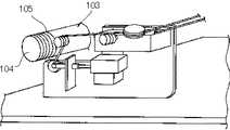
このようなセンターベルトの製造方法としては、凹凸を有する金型100にカバー帆布101とゴムシート102を載置してプレスすることで片面に凹条部19を含む凹凸を有する内層4aとなる帆布付の複合シート103を作製する(図3)。その複合シート103を所定の周長になるようカットして、例えば図4に示すようなスピニング装置を用いて、円筒形の金型104に巻きつけて上から心線105をスピニングし、接着ゴム層(図示しない)を巻きつけて加硫しスリーブとする。As a method for manufacturing such a center belt, a
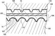
脱型したスリーブ106の凹凸のない側を研摩して所定厚みとし、外層4bとなるゴムシート107とカバー帆布108を積層する(図5)。上記で作製した凹凸と噛み合う凹凸形状を有する下側の金型100と新たに積層したゴムシート107に凹凸を設けるための凹凸形状を有する上側の金型109との間でプレスして外層側にも凹条部18を含む凹凸を形成するとともにゴムを加硫する(図6)。順送りに未加硫部分を加硫していくことによってベルトスリーブ全周を加硫することができる。次いで所定幅にカットすることによってセンターベルトを製造することができる。(4) The unmolded side of the removed
本発明ではこのゴムシートに凹凸を形成したり加硫したりする工程において、図3に示すように金型100の表面に離型フィルム110を配置してベルトを形成するゴム102やカバー帆布101との間に介在することによって、金型100に離型剤を吹き付けたり塗布しなくても金型の凹凸内にゴムが付着してしまうこともなく良好に脱型することができる。もちろん、上側の金型109や円筒形の金型104にも離型フィルム110を適用することができる。In the present invention, in the step of forming unevenness or vulcanizing the rubber sheet, as shown in FIG. 3, a
この離型フィルム110として用いることができるものとしては、ポリオレフィンフィルム、ポリエステル、ナイロン、ポリプロピレン、アセテートなどの樹脂からなるフィルムを用いることとができる。この中でもポリオレフィンフィルム、更にはポリオレフィンの中でもメチルペンテンコポリマーからなるフィルムを用いることが、凹凸形状を有するセンターベルトを製造する場合に伸縮性やしなやかさに富んでいることから好ましいといえる。メチルペンテンコポリマーからなるポリオレフィンフィルムとしては三井化学株式会社製のOpulent オピュラン(登録商標)を挙げることができる。で き る As a film that can be used as the
ポリオレフィンフィルムとしては厚みが30〜50μmのものを用いることができる。厚みが30μm未満であるとベルトの成形時や加硫の際に破損してしまうことがあり、50μmを超える厚みとなると伸縮性としなやかさが十分でなくなり、凹凸を有する金型の形状に沿いにくくなるのでできあがったベルトの凹凸の寸法が許容範囲でなくなってしまうという可能性が高くなるので好ましくない。の も の A polyolefin film having a thickness of 30 to 50 μm can be used. If the thickness is less than 30 μm, the belt may be damaged during molding or vulcanization, and if the thickness exceeds 50 μm, the elasticity and suppleness may not be sufficient, and the shape may be in accordance with the shape of a mold having irregularities. This is not preferable because it becomes more difficult to increase the possibility that the size of the concavities and convexities of the completed belt will be out of the allowable range.
また、上記のような離型フィルムに転写マークを載せておくことによって、センターベルトの加硫時にベルトにマークを転写してマーキングすることができる。転写マークは、未加硫のカラーゴム組成物、例えば天然ゴム、クロロプレンゴム、スチレンブタジエンゴムなどのゴムに加硫剤、加硫助剤、顔料などを配合したものを印刷することによって形成することができる。また、離型フィルムは金型の凹凸形状にそってベルト全面に密着するのでセンターベルトの凸になった部分のみでなく凹状部の底にもまたがったマークとすることも可能である。Also, by placing the transfer marks on the release film as described above, the marks can be transferred to the belt during vulcanization of the center belt for marking. The transfer mark is formed by printing an unvulcanized color rubber composition, for example, a rubber, such as natural rubber, chloroprene rubber, or styrene-butadiene rubber, mixed with a vulcanizing agent, a vulcanizing aid, a pigment, and the like. Can be. Further, since the release film adheres to the entire surface of the belt along the concave and convex shape of the mold, it is possible to form a mark not only on the convex portion of the center belt but also on the bottom of the concave portion.
更に、本発明の製造方法においてセンターベルトの脱型時に離型フィルム110が剥がれてしまい、複数の工程において工程の数だけの離型フィルムを使用することになる。そこで、離型フィルム110のセンターベルトと当接する側に予めコート層を設けたものを用い、意図的にセンターベルト側に付着させた状態で脱型できるようにすれば、離型フィルムをつけたまま次の工程に移行でき、複数の工程でそのまま離型フィルムを使用することができるようになる。この離型フィルム110に設けるコート層として用いることができるものは、ポリテトラフルオロエチレンなどのフッ素樹脂やウレタンなどを挙げることができる。また、離型フィルム上に設ける方法であるが、液状になるものであればスプレー塗布したり、流し込んだりするなどの方法を採ることができ、その他液状になりにくい場合はシート状のものを貼りつけるなど方法で設けることができる。(4) Further, in the manufacturing method of the present invention, the
以上のようにして得られたセンターベルトの凹条部18、19にブロック2を嵌め込んでいくことによって最終的に高負荷伝動ベルト1を得ることができる。高 The high-
また、ブロック内に例えばアルミ合金などからなるインサート材を埋設したブロックでも、インサート材を埋設していないブロックでもどちらでも用いることができる。Either a block in which an insert material such as an aluminum alloy is embedded in the block or a block in which no insert material is embedded can be used.
ブロックの樹脂として用いることができるのは、ポリアミド樹脂、ポリアミドイミド(PAI)樹脂、ポリフェニレンスルフィド(PPS)樹脂、ポリブチレンテレフタレート(PBT)樹脂、ポリイミド(PI)樹脂、ポリエーテルスルフォン(PES)樹脂、ポリエーテルエーテルケトン(PEEK)樹脂等の合成樹脂が用いられるが、中でも低摩擦係数で耐摩耗性に優れ、剛性があるとともに曲げに対しても弾力性を有しており、簡単に破損してしまうことのない樹脂がよく、ポリアミド樹脂、なかでもナイロン46が好ましいといえる。As the resin of the block, polyamide resin, polyamide imide (PAI) resin, polyphenylene sulfide (PPS) resin, polybutylene terephthalate (PBT) resin, polyimide (PI) resin, polyether sulfone (PES) resin, Synthetic resin such as polyetheretherketone (PEEK) resin is used. Among them, it has low friction coefficient and excellent abrasion resistance. It has rigidity and elasticity against bending. It is preferable to use a resin that does not end up, and it is preferable to use a polyamide resin, particularly, nylon 46.
本発明では前述のようにブロックを形成する合成樹脂中に繊維状の補強材やウィスカ状の補強材を配合することは可能であり、繊維状の補強材は15〜40重量%の範囲で配合する。15重量%未満であると補強効果が少なくブロックの耐磨耗性が十分でないなどの問題があり、40重量%を超えると樹脂への配合が困難になることや射出成形が困難になるなどの問題があるので好ましくない。In the present invention, a fibrous reinforcing material or a whisker-like reinforcing material can be compounded in the synthetic resin forming the block as described above, and the fibrous reinforcing material is compounded in a range of 15 to 40% by weight. I do. If it is less than 15% by weight, there is a problem that the reinforcing effect is small and the abrasion resistance of the block is not sufficient. It is not preferable because there is a problem.
合成樹脂に配合する繊維状補強材としては、アラミド繊維、炭素繊維、ガラス繊維、ポリアミド繊維、ポリエステル繊維などを挙げることができる。その中でも前記のブロックを構成する樹脂で好ましい例であるナイロン46と炭素繊維を組み合わせて用いることによって炭素繊維がナイロン46の吸水性の欠点を改善し、剛性を大幅に向上させることができて、且つナイロン46の有する耐摩耗性、耐衝撃性、耐疲労性を生かすことができるものである。繊 維 Examples of the fibrous reinforcing material to be added to the synthetic resin include aramid fiber, carbon fiber, glass fiber, polyamide fiber, polyester fiber and the like. Among them, by using a combination of nylon 46 and carbon fiber, which are preferable examples of the resin constituting the block, carbon fibers improve the water absorbing defect of nylon 46 and can significantly improve rigidity. In addition, the wear resistance, impact resistance, and fatigue resistance of nylon 46 can be utilized.
また、前記繊維状補強材として上記の有機繊維のほかにも酸化亜鉛ウィスカ、チタン酸カリウムウィスカ、ホウ酸アルミニウムウィスカなどの無機繊維を配合してもよい。In addition, as the fibrous reinforcing material, inorganic fibers such as zinc oxide whiskers, potassium titanate whiskers, and aluminum borate whiskers may be blended in addition to the above organic fibers.
また、酸化亜鉛ウィスカは、高比重、高剛性であるため、プーリとの接触時の振動を低減でき、ノイズの発生を小さくすることができる。なお、この酸化亜鉛ウィスカの配合量が少ない場合は添加した効果が発現せず、多すぎると混練できず、成形することが困難となる。亜 鉛 Because the zinc oxide whisker has high specific gravity and high rigidity, the vibration at the time of contact with the pulley can be reduced, and the generation of noise can be reduced. When the amount of the zinc oxide whisker is small, the added effect is not exhibited, and when the amount is too large, kneading cannot be performed, and molding becomes difficult.
このような材料構成とすることによって、プーリと接する際に受ける側圧にも十分に耐えうる剛性、靭性等の強度を有するとともに、耐摩耗性に優れ、更には、摩擦時に発生する熱に対しても強いブロックとすることが可能となり、プーリから受ける動力を効率よくセンターベルト3a、3bに引張力として伝えることができ、引張伝動式の高負荷伝動ベルトを構成することができる。By adopting such a material configuration, it has sufficient strength such as rigidity and toughness that can sufficiently withstand the side pressure received when it comes into contact with the pulley, has excellent wear resistance, and furthermore, with respect to heat generated during friction. It is also possible to form a strong block, and the power received from the pulley can be efficiently transmitted to the
なお、これらの他に、二硫化モリブデン、グラファイト、フッ素系樹脂から選ばれてなる少なくとも一つを混入することによってもブロック2の潤滑性を向上させることができる。フッ素系樹脂としては、ポリ4フッ化エチレン(PTFE)、ポリフッ化エチレンプロピレンエーテル(PFPE)、4フッ化エチレン6フッ化プロピレン共重合体(PFEP)、ポリフッ化アルコキシエチレン(PFA)等が挙げられる。潤滑 In addition, the lubricity of the
センターベルト3a、3bのゴム4として使用されるものは、クロロプレンゴム、天然ゴム、ニトリルゴム、スチレン−ブタジエンゴム、水素化ニトリルゴムなどの単一材またはこれらを適宜ブレンドしたゴムあるいはポリウレタンゴム等が挙げられる。そして、心体5としてはポリエステル繊維、ポリアミド繊維、アラミド繊維、ガラス繊維、スチールワイヤ等から選ばれたロープが用いられる。The rubber used for the
図7に示すのは、本発明の製造方法で得られたセンターベルトを適用できる別のベルトの例であり、ビーム部31の両端から上方に向かって一対のサイドピラー32、33が延びており、このサイドピラー32、33の上端からそれぞれブロック2の中心に向かって延びるロック部34、35が対向するように設けられている。そして、これらビーム部31、サイドピラー32、33及びロック部34、35によってセンターベルト3a、3bが嵌合する嵌合溝30が形成されている。この嵌合溝30に、センターベルト3a、3bが、ロック部34、35間の開口部より挿入され装着される。また、ロック部34、35の嵌合溝30側には、凸部37がそれぞれ設けられており、この凸部37が、センターベルト3a、3bに所定ピッチで設けられている凹部36に嵌合する。これによって、センターベルト3a、3bは、装着後はブロック2から抜けにくい状態となる。FIG. 7 shows another example of a belt to which the center belt obtained by the manufacturing method of the present invention can be applied. A pair of
本発明は自動車や自動二輪車、一般産業機械、農業機械などの駆動に用いられるベルトの張力体となるセンターベルトの製造方法として利用される。The present invention is used as a method for manufacturing a center belt which is a tension member of a belt used for driving an automobile, a motorcycle, a general industrial machine, an agricultural machine, or the like.
1 高負荷伝動ベルト
2 ブロック
3a センターベルト
3b センターベルト
4 ゴム
4a 内層
4b 外層
5 心体
11 上ビーム部
12 下ビーム部
13 センターピラー
14 溝
15 溝
16 溝上面
17 溝下面
18 凹条部
19 凹条部
20 凸条部
21 凸条部
100 金型
101 カバー帆布
102 ゴムシート
103 複合シート
104 金型
105 心線
106 スリーブ
107 ゴムシート
108 カバー帆布
109 金型
DESCRIPTION OF
Claims (5)
Translated fromJapaneseThe method for manufacturing a center belt according to any one of claims 1 to 3, wherein a coating layer is provided in advance on a side of the release film that contacts the center belt.
Priority Applications (1)
| Application Number | Priority Date | Filing Date | Title |
|---|---|---|---|
| JP2003309171AJP2004106545A (en) | 2002-08-30 | 2003-09-01 | Manufacturing process of center belt |
Applications Claiming Priority (2)
| Application Number | Priority Date | Filing Date | Title |
|---|---|---|---|
| JP2002254889 | 2002-08-30 | ||
| JP2003309171AJP2004106545A (en) | 2002-08-30 | 2003-09-01 | Manufacturing process of center belt |
Publications (1)
| Publication Number | Publication Date |
|---|---|
| JP2004106545Atrue JP2004106545A (en) | 2004-04-08 |
Family
ID=32301369
Family Applications (1)
| Application Number | Title | Priority Date | Filing Date |
|---|---|---|---|
| JP2003309171APendingJP2004106545A (en) | 2002-08-30 | 2003-09-01 | Manufacturing process of center belt |
Country Status (1)
| Country | Link |
|---|---|
| JP (1) | JP2004106545A (en) |
Cited By (1)
| Publication number | Priority date | Publication date | Assignee | Title |
|---|---|---|---|---|
| WO2005114002A1 (en)* | 2004-05-22 | 2005-12-01 | Contitech Antriebssysteme Gmbh | High performance hybrid v-belt |
- 2003
- 2003-09-01JPJP2003309171Apatent/JP2004106545A/enactivePending
Cited By (1)
| Publication number | Priority date | Publication date | Assignee | Title |
|---|---|---|---|---|
| WO2005114002A1 (en)* | 2004-05-22 | 2005-12-01 | Contitech Antriebssysteme Gmbh | High performance hybrid v-belt |
Similar Documents
| Publication | Publication Date | Title |
|---|---|---|
| JP6088985B2 (en) | Friction transmission belt, method for manufacturing the same, and belt transmission device | |
| JPH0531012B2 (en) | ||
| EP1218871B1 (en) | Indicia bearing elastomeric article | |
| JP2004106545A (en) | Manufacturing process of center belt | |
| JP6352724B2 (en) | Endless flat belt and manufacturing method thereof | |
| US20080047656A1 (en) | Method of manufacturing a belt | |
| CN110682565A (en) | Method for manufacturing ribbed belt with rib coating | |
| JPH0553977B2 (en) | ||
| JP2003311847A (en) | Method of manufacturing center belt for heavy load transmission belt | |
| EP0492960A1 (en) | Method of transferring an identifying mark onto a belt/belt sleeve | |
| JP2003145636A (en) | Method for manufacturing center belt for high load transmission belt | |
| JP2008006713A (en) | Manufacturing method for double-sided toothed belt | |
| JP2008213145A (en) | Method for producing transmission belt and transmission belt | |
| JP2011251537A (en) | Method of manufacturing power transmitting belt | |
| JP2008265031A (en) | Manufacturing method for transmission belt | |
| JP4772518B2 (en) | Manufacturing method of power transmission belt | |
| JPS59208245A (en) | Multirib belt and manufacture thereof | |
| JPH08281828A (en) | Transmission belt manufacturing method | |
| JP2003191334A (en) | Method for connecting reinforcing cloth of center belt for high load transmission belt | |
| JP2003314626A (en) | Center belt for high-load transmitting belt and high-load transmitting belt | |
| JPH0353107B2 (en) | ||
| JP2001263432A (en) | Manufacturing method of belt for power transmission | |
| JP2008241031A (en) | Belt for power transmission | |
| JP2006168356A (en) | Manufacturing method of center belt | |
| JP2008030460A (en) | Manufacturing process of driving belt |