JP2004105219A - Training apparatus - Google Patents
Training apparatusDownload PDFInfo
- Publication number
- JP2004105219A JP2004105219AJP2002267813AJP2002267813AJP2004105219AJP 2004105219 AJP2004105219 AJP 2004105219AJP 2002267813 AJP2002267813 AJP 2002267813AJP 2002267813 AJP2002267813 AJP 2002267813AJP 2004105219 AJP2004105219 AJP 2004105219A
- Authority
- JP
- Japan
- Prior art keywords
- training
- base
- footrest
- slide
- slide base
- Prior art date
- Legal status (The legal status is an assumption and is not a legal conclusion. Google has not performed a legal analysis and makes no representation as to the accuracy of the status listed.)
- Granted
Links
- 238000012549trainingMethods0.000titleclaimsabstractdescription110
- 230000033001locomotionEffects0.000abstractdescription38
- 230000007246mechanismEffects0.000abstractdescription7
- 238000010586diagramMethods0.000description15
- 238000012545processingMethods0.000description10
- 238000001514detection methodMethods0.000description9
- 238000004891communicationMethods0.000description6
- 238000000034methodMethods0.000description6
- 238000013523data managementMethods0.000description4
- 230000002093peripheral effectEffects0.000description4
- 230000033764rhythmic processEffects0.000description4
- 238000004364calculation methodMethods0.000description3
- 235000019577caloric intakeNutrition0.000description3
- 238000012790confirmationMethods0.000description3
- 210000003414extremityAnatomy0.000description3
- 238000012986modificationMethods0.000description3
- 230000004048modificationEffects0.000description3
- 210000003205muscleAnatomy0.000description3
- 230000008569processEffects0.000description3
- 230000005540biological transmissionEffects0.000description2
- 230000008878couplingEffects0.000description2
- 238000010168coupling processMethods0.000description2
- 238000005859coupling reactionMethods0.000description2
- 238000013500data storageMethods0.000description2
- 230000000694effectsEffects0.000description2
- 230000007935neutral effectEffects0.000description2
- 230000003014reinforcing effectEffects0.000description2
- 102100035353Cyclin-dependent kinase 2-associated protein 1Human genes0.000description1
- 210000003489abdominal muscleAnatomy0.000description1
- 230000001133accelerationEffects0.000description1
- 239000003086colorantSubstances0.000description1
- 239000012141concentrateSubstances0.000description1
- 239000004020conductorSubstances0.000description1
- 238000007796conventional methodMethods0.000description1
- 238000012937correctionMethods0.000description1
- 230000007423decreaseEffects0.000description1
- 239000013013elastic materialSubstances0.000description1
- 230000003203everyday effectEffects0.000description1
- 238000009434installationMethods0.000description1
- 210000003127kneeAnatomy0.000description1
- 210000002414legAnatomy0.000description1
- 238000007726management methodMethods0.000description1
- 238000005259measurementMethods0.000description1
- 239000002184metalSubstances0.000description1
- 230000004044responseEffects0.000description1
- 230000009885systemic effectEffects0.000description1
- 230000007704transitionEffects0.000description1
- 238000012384transportation and deliveryMethods0.000description1
Images


Classifications
- A—HUMAN NECESSITIES
- A63—SPORTS; GAMES; AMUSEMENTS
- A63B—APPARATUS FOR PHYSICAL TRAINING, GYMNASTICS, SWIMMING, CLIMBING, OR FENCING; BALL GAMES; TRAINING EQUIPMENT
- A63B22/00—Exercising apparatus specially adapted for conditioning the cardio-vascular system, for training agility or co-ordination of movements
- A63B22/20—Exercising apparatus specially adapted for conditioning the cardio-vascular system, for training agility or co-ordination of movements using rollers, wheels, castors or the like, e.g. gliding means, to be moved over the floor or other surface, e.g. guide tracks, during exercising
- A63B22/201—Exercising apparatus specially adapted for conditioning the cardio-vascular system, for training agility or co-ordination of movements using rollers, wheels, castors or the like, e.g. gliding means, to be moved over the floor or other surface, e.g. guide tracks, during exercising for moving a support element in reciprocating translation, i.e. for sliding back and forth on a guide track
- A63B22/203—Exercising apparatus specially adapted for conditioning the cardio-vascular system, for training agility or co-ordination of movements using rollers, wheels, castors or the like, e.g. gliding means, to be moved over the floor or other surface, e.g. guide tracks, during exercising for moving a support element in reciprocating translation, i.e. for sliding back and forth on a guide track in a horizontal plane
- A—HUMAN NECESSITIES
- A63—SPORTS; GAMES; AMUSEMENTS
- A63B—APPARATUS FOR PHYSICAL TRAINING, GYMNASTICS, SWIMMING, CLIMBING, OR FENCING; BALL GAMES; TRAINING EQUIPMENT
- A63B23/00—Exercising apparatus specially adapted for particular parts of the body
- A63B23/035—Exercising apparatus specially adapted for particular parts of the body for limbs, i.e. upper or lower limbs, e.g. simultaneously
- A63B23/04—Exercising apparatus specially adapted for particular parts of the body for limbs, i.e. upper or lower limbs, e.g. simultaneously for lower limbs
- A—HUMAN NECESSITIES
- A63—SPORTS; GAMES; AMUSEMENTS
- A63B—APPARATUS FOR PHYSICAL TRAINING, GYMNASTICS, SWIMMING, CLIMBING, OR FENCING; BALL GAMES; TRAINING EQUIPMENT
- A63B21/00—Exercising apparatus for developing or strengthening the muscles or joints of the body by working against a counterforce, with or without measuring devices
- A63B21/02—Exercising apparatus for developing or strengthening the muscles or joints of the body by working against a counterforce, with or without measuring devices using resilient force-resisters
- A63B21/023—Wound springs
- A—HUMAN NECESSITIES
- A63—SPORTS; GAMES; AMUSEMENTS
- A63B—APPARATUS FOR PHYSICAL TRAINING, GYMNASTICS, SWIMMING, CLIMBING, OR FENCING; BALL GAMES; TRAINING EQUIPMENT
- A63B22/00—Exercising apparatus specially adapted for conditioning the cardio-vascular system, for training agility or co-ordination of movements
- A63B22/14—Platforms for reciprocating rotating motion about a vertical axis, e.g. axis through the middle of the platform
- A—HUMAN NECESSITIES
- A63—SPORTS; GAMES; AMUSEMENTS
- A63B—APPARATUS FOR PHYSICAL TRAINING, GYMNASTICS, SWIMMING, CLIMBING, OR FENCING; BALL GAMES; TRAINING EQUIPMENT
- A63B24/00—Electric or electronic controls for exercising apparatus of preceding groups; Controlling or monitoring of exercises, sportive games, training or athletic performances
- A—HUMAN NECESSITIES
- A63—SPORTS; GAMES; AMUSEMENTS
- A63B—APPARATUS FOR PHYSICAL TRAINING, GYMNASTICS, SWIMMING, CLIMBING, OR FENCING; BALL GAMES; TRAINING EQUIPMENT
- A63B69/00—Training appliances or apparatus for special sports
- A63B69/18—Training appliances or apparatus for special sports for skiing
- A—HUMAN NECESSITIES
- A63—SPORTS; GAMES; AMUSEMENTS
- A63B—APPARATUS FOR PHYSICAL TRAINING, GYMNASTICS, SWIMMING, CLIMBING, OR FENCING; BALL GAMES; TRAINING EQUIPMENT
- A63B71/00—Games or sports accessories not covered in groups A63B1/00 - A63B69/00
- A63B71/06—Indicating or scoring devices for games or players, or for other sports activities
- A63B71/0619—Displays, user interfaces and indicating devices, specially adapted for sport equipment, e.g. display mounted on treadmills
- A63B71/0622—Visual, audio or audio-visual systems for entertaining, instructing or motivating the user
- A—HUMAN NECESSITIES
- A63—SPORTS; GAMES; AMUSEMENTS
- A63B—APPARATUS FOR PHYSICAL TRAINING, GYMNASTICS, SWIMMING, CLIMBING, OR FENCING; BALL GAMES; TRAINING EQUIPMENT
- A63B22/00—Exercising apparatus specially adapted for conditioning the cardio-vascular system, for training agility or co-ordination of movements
- A63B22/0025—Particular aspects relating to the orientation of movement paths of the limbs relative to the body; Relative relationship between the movements of the limbs
- A63B2022/0028—Particular aspects relating to the orientation of movement paths of the limbs relative to the body; Relative relationship between the movements of the limbs the movement path being non-parallel to the body-symmetrical-plane, e.g. support elements moving at an angle to the body-symmetrical-plane
- A63B2022/003—Particular aspects relating to the orientation of movement paths of the limbs relative to the body; Relative relationship between the movements of the limbs the movement path being non-parallel to the body-symmetrical-plane, e.g. support elements moving at an angle to the body-symmetrical-plane the movement path being perpendicular to the body-symmetrical-plane
- A—HUMAN NECESSITIES
- A63—SPORTS; GAMES; AMUSEMENTS
- A63B—APPARATUS FOR PHYSICAL TRAINING, GYMNASTICS, SWIMMING, CLIMBING, OR FENCING; BALL GAMES; TRAINING EQUIPMENT
- A63B22/00—Exercising apparatus specially adapted for conditioning the cardio-vascular system, for training agility or co-ordination of movements
- A63B22/0025—Particular aspects relating to the orientation of movement paths of the limbs relative to the body; Relative relationship between the movements of the limbs
- A63B2022/0033—Lower limbs performing together the same movement, e.g. on a single support element
- A—HUMAN NECESSITIES
- A63—SPORTS; GAMES; AMUSEMENTS
- A63B—APPARATUS FOR PHYSICAL TRAINING, GYMNASTICS, SWIMMING, CLIMBING, OR FENCING; BALL GAMES; TRAINING EQUIPMENT
- A63B21/00—Exercising apparatus for developing or strengthening the muscles or joints of the body by working against a counterforce, with or without measuring devices
- A63B21/02—Exercising apparatus for developing or strengthening the muscles or joints of the body by working against a counterforce, with or without measuring devices using resilient force-resisters
- A63B21/04—Exercising apparatus for developing or strengthening the muscles or joints of the body by working against a counterforce, with or without measuring devices using resilient force-resisters attached to static foundation, e.g. a user
- A63B21/0407—Anchored at two end points, e.g. installed within an apparatus
- A63B21/0421—Anchored at two end points, e.g. installed within an apparatus the ends moving relatively by a pivoting arrangement
- A—HUMAN NECESSITIES
- A63—SPORTS; GAMES; AMUSEMENTS
- A63B—APPARATUS FOR PHYSICAL TRAINING, GYMNASTICS, SWIMMING, CLIMBING, OR FENCING; BALL GAMES; TRAINING EQUIPMENT
- A63B2208/00—Characteristics or parameters related to the user or player
- A63B2208/02—Characteristics or parameters related to the user or player posture
- A63B2208/0204—Standing on the feet
- A—HUMAN NECESSITIES
- A63—SPORTS; GAMES; AMUSEMENTS
- A63B—APPARATUS FOR PHYSICAL TRAINING, GYMNASTICS, SWIMMING, CLIMBING, OR FENCING; BALL GAMES; TRAINING EQUIPMENT
- A63B2220/00—Measuring of physical parameters relating to sporting activity
- A63B2220/10—Positions
- A63B2220/13—Relative positions
- A—HUMAN NECESSITIES
- A63—SPORTS; GAMES; AMUSEMENTS
- A63B—APPARATUS FOR PHYSICAL TRAINING, GYMNASTICS, SWIMMING, CLIMBING, OR FENCING; BALL GAMES; TRAINING EQUIPMENT
- A63B2220/00—Measuring of physical parameters relating to sporting activity
- A63B2220/50—Force related parameters
- A63B2220/51—Force
- A—HUMAN NECESSITIES
- A63—SPORTS; GAMES; AMUSEMENTS
- A63B—APPARATUS FOR PHYSICAL TRAINING, GYMNASTICS, SWIMMING, CLIMBING, OR FENCING; BALL GAMES; TRAINING EQUIPMENT
- A63B2225/00—Miscellaneous features of sport apparatus, devices or equipment
- A63B2225/15—Miscellaneous features of sport apparatus, devices or equipment with identification means that can be read by electronic means
- A—HUMAN NECESSITIES
- A63—SPORTS; GAMES; AMUSEMENTS
- A63B—APPARATUS FOR PHYSICAL TRAINING, GYMNASTICS, SWIMMING, CLIMBING, OR FENCING; BALL GAMES; TRAINING EQUIPMENT
- A63B2225/00—Miscellaneous features of sport apparatus, devices or equipment
- A63B2225/20—Miscellaneous features of sport apparatus, devices or equipment with means for remote communication, e.g. internet or the like
- A—HUMAN NECESSITIES
- A63—SPORTS; GAMES; AMUSEMENTS
- A63B—APPARATUS FOR PHYSICAL TRAINING, GYMNASTICS, SWIMMING, CLIMBING, OR FENCING; BALL GAMES; TRAINING EQUIPMENT
- A63B2225/00—Miscellaneous features of sport apparatus, devices or equipment
- A63B2225/50—Wireless data transmission, e.g. by radio transmitters or telemetry
- A—HUMAN NECESSITIES
- A63—SPORTS; GAMES; AMUSEMENTS
- A63B—APPARATUS FOR PHYSICAL TRAINING, GYMNASTICS, SWIMMING, CLIMBING, OR FENCING; BALL GAMES; TRAINING EQUIPMENT
- A63B2244/00—Sports without balls
- A63B2244/22—Dancing
- A—HUMAN NECESSITIES
- A63—SPORTS; GAMES; AMUSEMENTS
- A63B—APPARATUS FOR PHYSICAL TRAINING, GYMNASTICS, SWIMMING, CLIMBING, OR FENCING; BALL GAMES; TRAINING EQUIPMENT
- A63B23/00—Exercising apparatus specially adapted for particular parts of the body
- A63B23/02—Exercising apparatus specially adapted for particular parts of the body for the abdomen, the spinal column or the torso muscles related to shoulders (e.g. chest muscles)
- A63B23/0205—Abdomen
- A63B23/0222—Abdomen moving torso and lower limbs
- A—HUMAN NECESSITIES
- A63—SPORTS; GAMES; AMUSEMENTS
- A63B—APPARATUS FOR PHYSICAL TRAINING, GYMNASTICS, SWIMMING, CLIMBING, OR FENCING; BALL GAMES; TRAINING EQUIPMENT
- A63B26/00—Exercising apparatus not covered by groups A63B1/00 - A63B25/00
- A63B26/003—Exercising apparatus not covered by groups A63B1/00 - A63B25/00 for improving balance or equilibrium
- A—HUMAN NECESSITIES
- A63—SPORTS; GAMES; AMUSEMENTS
- A63B—APPARATUS FOR PHYSICAL TRAINING, GYMNASTICS, SWIMMING, CLIMBING, OR FENCING; BALL GAMES; TRAINING EQUIPMENT
- A63B69/00—Training appliances or apparatus for special sports
- A63B69/0093—Training appliances or apparatus for special sports for surfing, i.e. without a sail; for skate or snow boarding
- A—HUMAN NECESSITIES
- A63—SPORTS; GAMES; AMUSEMENTS
- A63B—APPARATUS FOR PHYSICAL TRAINING, GYMNASTICS, SWIMMING, CLIMBING, OR FENCING; BALL GAMES; TRAINING EQUIPMENT
- A63B71/00—Games or sports accessories not covered in groups A63B1/00 - A63B69/00
- A63B71/06—Indicating or scoring devices for games or players, or for other sports activities
- A63B71/0686—Timers, rhythm indicators or pacing apparatus using electric or electronic means
Landscapes
- Health & Medical Sciences (AREA)
- General Health & Medical Sciences (AREA)
- Physical Education & Sports Medicine (AREA)
- Cardiology (AREA)
- Vascular Medicine (AREA)
- Orthopedic Medicine & Surgery (AREA)
- Engineering & Computer Science (AREA)
- Life Sciences & Earth Sciences (AREA)
- Biophysics (AREA)
- Multimedia (AREA)
- Human Computer Interaction (AREA)
- Rehabilitation Tools (AREA)
Abstract
Description
Translated fromJapanese【0001】
【発明の属する技術分野】
本発明は、スライド運動及びツイスト運動を同時に行うトレーニング装置に関するものである。
【0002】
【従来の技術】
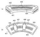
従来、スライド運動やツイスト運動を行うことのできるトレーニング装置が知られている。この装置は、図14(a)、(b)に示すように、ベース401はアーチ形状の軌道402を有し、この軌道402上に2本の同心円通路403、404が形成され、そして、可動台405、406が同心円通路403、404に沿って移動可能に設けられていると共に、この各可動台405、406には、足置き台としての靴407が各可動台405,406の水平面内で回転可能に取り付けられているものである。プレイヤは、靴407上に乗り(左右の足を置き)、可動台405、406を同心円通路403、404に沿って移動させてスライド運動を行ったり、あるいは、靴407を回転させてツイスト運動を行うことによって、スキー等のトレーニングができる。
【0003】
また、従来装置として、図15に示すように、滑り台501上に、横長な溝502を切った第1の枠503を固着し、その第1の枠503の溝502の中に、回転する円形の第2の枠504を設け、さらに、第2の枠504の中に、回転する2個の円形のターンテーブル505を設けたものが知られている。プレイヤはターンテーブル505上に両足を乗せ、左右方向へのスライド運動を行ったり、ツイスト運動を行うことによって、スキー等のトレーニングを行うことができる。
【0004】
【発明が解決しようとする課題】
日常生活やスポーツシーンにおいて、不安定なポジション(姿勢)で体を動かす機会は非常に多い。この不安定な状態で体のバランスを取ろうとするとき、四肢(手足)だけでなく、腹筋や背筋といった、所謂体幹部に力を入れていることが多い。したがって、体のトレーニングを行う場合、四肢のトレーニングだけでなく、体幹部のトレーニングを併行して行うことが重要となる。
【0005】
しかしながら、上記従来の技術では、左右の足置き台が個々に移動や回転するものであるため、スライド運動もツイスト運動もそれぞれの足で分散して行うものとなる。
【0006】
また、従来装置として、左右の足置き台が連携して可動する装置が知られているが、この装置は、足元に加える力の方向を単に変えるだけで移動が可能となるものであるため、全身的な運動効果が期待し難い。また、運動中は足元のみに注意を払えばよいことから、次の運動への移行も容易であり、体幹部が有効に鍛えられるものではないという問題がある。
【0007】
本発明は、上記の問題点に鑑みてなされたものであり、その目的は、足踏み動作などを必要とせずスライド運動とツイスト運動とを連動して行え、体幹部を効果的にトレーニングできるトレーニング装置を提供することにある。
【0008】
【課題を解決するための手段】
請求項1記載の発明は、左右方向に延びるガイドレールを備えた基台と、上記ガイドレールに沿ってスライド移動可能なスライド基部と、上記スライド基部の上部に回動可能に設けられた足置き台と、上記足置き台のスライド位置と回動角とを関連付けるべく上記基台の左右方向略中間の適所と上記足置き台とを係合する連結手段と、上記スライド基部に上記基台の左右方向略中間位置に向かう付勢力を与える付勢手段とを備えたトレーニング装置である。
【0009】
上記構成によれば、スライド基部をガイドレールに沿って左右方向にスライド移動させると、スライド基部上の足置き台は、連結手段が設けられたことにより、スライド移動距離に応じた角度だけスライド基部に対して回転する。すなわち、スライド基部がスライド運動すると、足置き台はスライド移動方向で揺動運動する。また、復元力を発生するための付勢手段が設けられたことにより、左右にスライド移動した足置き台は、ガイドレールの長手方向中央部の中立位置に自動的に復帰されると共に、左右にスライド移動させる際には適当な負荷が発生し、トレーニング上好ましい。プレイヤは、足置き台に両足を乗せた状態で、体のバランスを崩すことなくスライド運動とツイスト運動とが同時に実行可能となり、体幹部が効果的にトレーニングされる。
【0010】
請求項2記載の発明は、請求項1記載のトレーニング装置において、上記連結手段は、一端が上記足置き台に連結された揺動アームと、この揺動アームの他端側を回動かつ摺動自在に支持する上記基台に設けられた揺動アーム支持部とを備えることを特徴とする。この構成によれば、足置き台の回転運動は、揺動アームを揺動運動の腕として、かつ揺動アーム支持部を回転中心(軸)としてスライド運動と連動して行われる。
【0011】
請求項3記載の発明は、請求項2記載のトレーニング装置において、上記揺動アームは棒状体からなり、上記揺動アーム支持部は上記棒状体を挟持するローラ対を含むことを特徴とする。この構成によれば、揺動アームが簡易な構造となる。また、揺動アームがローラ対の挟持位置で揺動中心となると共に摺動することで揺動動作が実現される。
【0012】
請求項4記載の発明は、請求項1〜3のいずれかに記載のトレーニング装置において、上記ガイドレールは2本が並設されてなり、上記スライド基部はその前後方向両端部で各ガイドレールを挟持するものであることを特徴とする。この構成によれば、スライド基部は安定してスライド移動される。
【0013】
請求項5記載の発明は、請求項1〜4のいずれかに記載のトレーニング装置において、上記スライド基部は上記ガイドレールを上下方向から挟持するローラ対を備えることを特徴とする。この構成によれば、スライド基部がガイドレールから外れるのが防止される。
【0014】
請求項6記載の発明は、請求項5記載のトレーニング装置において、上記ガイドレールを上下方向から挟持するローラ対のうち、上側のローラの軸は水平であり、下側のローラの軸は傾斜して配置されていることを特徴とする。この構成によれば、下側のローラの軸は、水平な場合に比して高い位置でスライド基部に軸支可能となるので、その分、スライド基部の高さ寸法が短縮され、したがってスライド基部をコンパクト化できる。
【0015】
請求項7記載の発明は、請求項1〜6のいずれかに記載のトレーニング装置において、上記付勢手段は、上記スライド基部と上記基台間に張設されたスプリングであることを特徴とする。この構成によれば、付勢手段が簡易な構造となる。
【0016】
請求項8記載の発明は、請求項1〜7のいずれかに記載のトレーニング装置において、上記基台は、手摺り部を備えていることを特徴とする。この構成によれば、手摺り部を掴むことにより、足置き台を両足で踏ん張ってスライド始動が容易となり、また、スライド運動と回転運動とを同時に行いながらも体のバランスが取り易くなる。
【0017】
請求項9記載の発明は、請求項1〜8のいずれかに記載のトレーニング装置において、トレーニングガイド用の画像を表示するモニタを備えることを特徴とする。この構成によれば、モニタ画面を介してトレーニングガイド用の画像が提供される。
【0018】
請求項10記載の発明は、請求項9記載のトレーニング装置において、上記モニタに表示されるトレーニングガイド用の画像の切換を指示操作するコントローラを備えることを特徴とする。この構成によれば、コントローラを介してプレイヤに所望のトレーニングガイドが提供される。
【0019】
請求項11記載の発明は、請求項10記載のトレーニング装置において、上記コントローラは、上記手摺り部に設けられていることを特徴とする。この構成によれば、足置き台に乗った状態でコントローラの操作が可能となる。
【0020】
【発明の実施の形態】
図1は、本発明に係るトレーニング装置の一実施形態を示す外観斜視図、図2は、図1のカバー類を取り外した状態での構造を示す図で、(a)は後方斜視図、(b)は前方斜視図、図3は、図2の平面図で、(a)は足置き部がスライドしていない状態を示す図、(b)は足置き部がスライドしている状態を示す図である。
【0021】
図1〜3に示すように、本トレーニング装置1は、基台10、スライド基部20、足置き部30(足置き台)、連結機構部40(連結手段)、付勢部50(付勢手段)を備えると共に、手摺り部60、ガイド部70、コントローラ80を備えている。
【0022】
図1において、本トレーニング装置1は、基台10に対して左右にスライド可能にされたスライド基部20を備えると共に、このスライド基部20の上部に回動可能な足置き部30を備え、この足置き部30上にプレイヤが乗って下半身部分を左右に移動自在にしたものである。手摺り部60はトレーニング中のプレイヤが把持することで運動し易さを援助するものであり、ガイド70はトレーニングガイド用の画像等をコンダクターとしてプレイヤに提供するものであり、コントローラ80はプレイヤにより操作可能にされ、トレーニングモードの選択その他の所要の内容を入力するものである。
【0023】
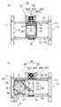
続いて、図2〜図5により、詳細構造を説明する。なお、図4は、基台10とスライド基部20との連結構造を示す図、図5は、足置き部30と連結機構部40との連結構造を説明する下方から見た図である。
【0024】
基台10は、左右一対の外枠11、左右の外枠11を連結する2本の渡し用梁12、渡し用梁12を強度的に補強する左右中央位置の中央梁13、左右の外枠11間に張られた2本の平行なスライドシャフト(ガイドレール)14、及び外枠11の内側に突設されたストッパ15を備えている。
【0025】
基部10は、左右一対の長尺の外枠11と前後の渡し用梁12とからなる四角形をなす枠組みを基本構造とするものである。スライドシャフト14は、所要長を有する断面が所定形状、本実施形態では円形である丸棒であり、両端が左右の外枠11に取り付けられ、かつ外枠11の前後方向に所定間隔だけ離れて並設されている。スライドシャフト14は、スライド基部20のスライドをガイドするレール(ステー)として機能する。ストッパ15は、ゴムなどの弾性材が突設されたもので、スライド基部20が左右方向にスライド移動した際の外枠11との衝突による衝撃を緩和するものである。
【0026】
スライド基部20は、四角形状を有する堅牢な金属製等からなる板状体で、各端辺が所要寸法だけ下方に屈曲された側壁が形成されると共に、側壁のうち前後側の側壁には対応して上コロ21と下コロ22とからなるローラ対が、左右方向に2対だけ取り付けられている。図4に示すように、上コロ21、下コロ22はいずれも周面がスライドガイド14の曲率に対応した凹面211,221に形成され、スライドガイド14に周面全体で当接し、上下方向でのスライドガイド14との確実な挟持を実現している。更に、図4に示すように、上コロ21は鎖線で示す水平な軸周りにスライド基部2の側壁201に軸支され、下コロ22の支持軸は側壁201から水平方向に対して45度未満の角度だけ下方に向けて、すなわち傾斜方向に設定されている。なお、前後の側壁201に設けられた下コロ22の傾斜の向きは、互いに反対、すなわち前後の下コロ22はハの字状を有し、これによりスライド基部20がスライドシャフト14から外れるのを効果的に防止している。しかも、スライド基部20の側壁201の上下方向の幅(高さ方向の幅)を、下コロ22を水平に支持する場合の幅に比して短縮できるので、スライド基部20の上下寸法をコンパクトにでき、かつスライド基部20上に配置される足置き部30の高さが低くできるので、プレイ動作を可及的に低い位置で行えると共に、プレイ位置への昇降を容易にできる。
【0027】
なお、上コロ21及び下コロ22からなるローラ対の個数は、1本のスライドシャフト14に対して2個の他、3個でもよく、要はスライド基部20の姿勢とスライドの安定性を確保し得る所定数であればよい。また、下コロ22は水平軸に軸支される態様であってもよい。
【0028】
足置き部30は、略四角形を有する板状体で、上面にトレー形状が形成されている。また、図5に示すように、足置き部30の裏面中央には、筒体31が突設されている。一方、スライド基部20の上面中央には、上記筒体31内に遊嵌可能な径寸法を有する円柱体23が突設されている。筒体31に円柱体23を嵌挿することによって、足置き部30がスライド基部20に対して回動可能に支持される。なお、筒体31は軸受であることが円滑な回動を実現する上で好ましい。
【0029】
連結機構部40は、基台10の左右方向略中間の適所と足置き部30とを係合する部位であり、揺動アームとしてのロッド41と、揺動アーム支持部42とから構成されている。ロッド41は一端(基端)が筒体31の外周に連結された所定長を有する断面円形の棒状体であり、揺動アーム支持部41は渡し用梁12の左右方向中間位置であって、前方に突出して設けられた水平基台421、水平基台421上に立設された支持台422、支持台422に回動自在に設けられた回動部材423、及び回動部材423上に配置された複数の立直軸にそれぞれ軸支されたコロ424とから構成されている。
【0030】
コロ424は左右に所定寸法、すなわちロッド41の直径寸法だけ離間して配置されたローラ対が前後に近接して合計2対が回動部材421の回動軸周りに設けられている。各ローラ対の間にはロッド41が挟持されている。本実施形態では、ローラ424の周面はロッド41の曲率と同一の凹面を有し、ロッド41と周面全体で当接するようにされている。かかる構成により、ロッド41は足置き部30(すなわちスライド基部20)が左右方向にスライド移動する際に、回動部材423の回動軸を中心に回動するようにされている。また、足置き部20の筒体23と回動部材423との距離は、足置き部30が左右方向にスライド移動することに応じて変化し、この変化に応じてロッド41の先端側は複数のコロ424から構成されるローラ対に挟持された状態で摺動することで吸収されており、これにより足置き部30の左右へのスライド移動が実現可能にされている。
【0031】
付勢部50は、スプリング(バネ)などの弾性体であり、一端はスライド基部20の前部に図略の止め具によって係止され、他端は中央梁13の後部に図略の止め具によって係止され、これによって、スライド基部20と基台10間に張設されている。なお、本実施形態では、スプリング51、52と2本並設しているが、本数は1本でもよく、あるいは3本としてもよい。付勢部50は、開放状態で左右方向中央位置にスライド基部20が復帰する付勢力を得るためと、左右へのスライド移動時にプレイヤに所要の負荷を与えるものとして機能する。
【0032】
なお、上記図3において、付勢部50は後方のスライドシャフト14側に近い位置で係止されているが、足置き部30が中央部に向けて付勢される構造であれば、前方のスライドシャフト14側に近い位置で係止してもよい。
【0033】
手摺り部60は、プレイヤが把持可能な径を有するパイプなどの棒状体からなり、左右の外枠11の前部から立直されプレイヤの肘の高さ位置で屈曲されて左右に亘る水平部が形成されている。左右の立直部は外枠11の後部から立直した補強パイプと連結されている。
【0034】
ガイド部70は、図1に示すように、長身の本体部71、本体部71の上部に配置された、所定の画像例えばトレーニング用の画像を表示するモニタ72、スピーカ73を備えると共に、高さ方向中間には足置き部30(あるいはスライド基部20)の左右位置を遠隔的に検出する赤外線センサ等のセンサ74が設けられている。また、後述のコントローラ80からの指令信号を受信する受信部75を備えている。
【0035】
コントローラ80は、個人情報、操作指示などの所定の情報を入力するためのもので、手摺り部60の所定位置、例えば略中央位置に取り付けられている。コントローラ80は、文字(例えば「START」等)や数字などのボタンを備えたテンキーユニット81、及び発信機からなどの所定の信号を受信するための受信部82、及びガイド部70の受信部75への所定の指示信号等を送信する送信部83を備えている。なお、受信部82は、例えばプレイヤの腕などに嵌められたトランスポンダTP(発信機、図7参照)付きリング(図示せず)を、近接する(かざす)ことによってトランスポンダTPからの送信信号を受信するものである。また、受信部75と送信部83との間の接続は有線の他、無線であってもよい。
【0036】
以上の構成につき、次に動作を説明する。
【0037】
足置き部30が中立の中央位置から左右方向、例えば図3(a)から図3(b)に示すように左方向(矢印Aの方向)へ移動すると、スライド基部20すなわち足置き部30は、スライドシャフト14に沿って左方向へ移動する。このとき、ロッド41の基端は足置き部30に固定されている一方、かつ、他端側は、コロ424によって回動支点となり、かつ摺動可能であるから、ロッド41はコロ424の中心すなわち回動部材423の軸を中心にして揺動する。すなわち、足置き部30はロッド41の揺動分だけ回転する。ロッド41の揺動量は、足置き部30のスライド量に対応するから、足置き部30は中央位置からの移動距離と回転角度とが対応する。
【0038】
以上のように、スライド基部20のスライド移動に伴って足置き部30が回転することにより、足置き部30上のプレイヤはスライド移動しながら体を捻った状態にすることができる。すなわち、図6に示すトレーニング動作の一例のように、プレイヤPはスライド運動と連動したツイスト運動を行うことができる。そして、この運動によって、脚部等、身体の一部のみを鍛える従来のトレーニング機器では実現できなかった全身運動が可能となる。また、本トレーニング装置によれば、スライド運動とツイスト運動によって全身のバランスが適度に崩れた状態で運動を行うことから、体幹部をも効果的にトレーニングすることができる。
【0039】
また、スライド移動した状態から中央位置に戻るときに、付勢部50による付勢力を利用することにより、連続運動を容易に行うことが可能となる。また、手摺り部60を設けることで、スライド運動及びツイスト運動時のバランスをとる動作や、足置き部30の回転角度を制御することによるスライド移動の加速、減速を自然な連続動作(円滑な動作)で行うことができる。
【0040】
さらに、足置き部30は、足を乗せる位置を足置き部30の前側にするほど、より大きな、スライド基部20(足置き台30)をスライド移動させる際の横(左右)方向に押す力と、足置き部30に加える回転力(捻り力)とが必要となり、逆に、足を乗せる位置を足置き台30の後側にするほど、横方向へ押す力が小さくて済むようになる。すなわち、足置き部30の立ち位置を前方にするとトレーニングの負荷が大きくなり、立ち位置を後方にするとトレーニングの負荷が小さくなる。したがって、ブレーキやウエイト等による負荷機構がない簡易な構造で、個人に適合した運動強度を設定できる。
【0041】
図7は、本トレーニング装置1におけるトレーニングガイドを行う制御系を示すブロック図である。制御部100は、本トレーニング装置の制御全般を行うためのCPUを備えると共に、トレーニング制御プログラムを記憶したROM101,処理途中のデータを一時的に記憶するRAM102及びモニタ72に表示するための画像データ及びスピーカ73へ送出する音声データを記憶するデータ記憶部103が接続されている。
【0042】
制御部100は、画像生成部1001、音声制御部1002、タイマ1003、検出信号処理部1004、演算部1005及び通信制御部1006を備える。画像生成部1001は、プレイヤ登録、トレーニングモード選択用及びトレーニングガイド用画像のモニタ72への表示を行わせるものである。音声制御部1002は、運動時の伴奏音、例えばリズム音等のスピーカ73への送出を行わせるものである。タイマ1003は、計時動作を行うものである。検出信号処理部1004は、センサ74からの検出信号に基づき、スライド基部20すなわちプレイヤPの検出情報を生成するものである。
【0043】
演算部1005は、タイマ1003、検出信号処理部1004からの情報、及びコントローラ80から入力された個人情報などに基づいて、プレイヤPのトレーニング状況を算出する部位である。例えば、検出信号処理部1004からの往復運動回数の情報、タイマ1003の計時情報から運動速度情報、あるいは、トランスポンダTPから発信されコントローラ71に入力された、性別、年齢などのプレイヤPの個人情報に基づき、スライド運動のタイミング、すなわち、足置き部30の操作タイミングや、トレーニングに要した消費カロリーなどを算出する。
【0044】
通信制御部1006は、トレーニング装置1外の所定の位置(例えば管理室あるいはネット回線を介してのサーバ内)に設けられたデータ管理部90との通信を行うものである。データ管理部90は、複数人の、例えば、トレーニング会員などの識別番号(会員番号)、トレーニング履歴などの個人情報のデータを管理するもので、制御部100で入手され、通信制御部1006から送信された情報に基づいて、個人の認証処理を行い、必要に応じて返信を行う。
【0045】
図8は、モニタへの表示処理を示すフローチャートである。通常時はモニタ72には、トレーニング時に表示される一連の映像が、デモンストレーション(外周デモ)映像として表示されている(ステップST1)。このデモ映像の表示中においてもモニタ72画面の一部にはトレーニング催促指示、例えば「ボタンを押してください」等の表示が継続されている。画面プレイヤPが、足置き部30上に乗り、この「ボタンを押してください」との指示を受けてコントローラ80のキーを押下すると(ステップST3でYES)、待機状態から、「電子KEYを持っている方は、テンキー上にかざしてください」との電子KEY入力画面に切り替えられる(ステップST5)。ここで、プレイヤPの電子KEYの有無を確認し(ステップST7)、電子KEYを持っている場合、トランスポンダTP付きリングなどの電子KEYを受信部82上にかざすと、トランスポンダTPからの個人情報が取り込まれる。この個人情報は、制御部100に取り込まれ、通信制御部1006を介してデータ管理部90と通信し、プレイヤPの認証(電子KEY確認)が行われる(ステップST9)。
【0046】
なお、電子KEY入力は、上記のような、「電子KEYを持っている方は、テンキー上にかざしてください」などのメッセージが表示されたタイミングでのみ行うことができ、それ以降は、例えば運動中に誤って電子KEYをコントローラ71にかざしたとしても入力を受け付けないようになっている。
【0047】
電子KEYの有無を確認し(ステップST7)、プレイヤPが電子KEYを持っていない場合、パーソナルデータ入力画面が表示され、この画面の案内に従って、個人情報をコントローラ80のテンキーユニット81から入力する(ステップST11)。この際、電子KEYを用いた場合と同様、制御部100は、通信制御部1006を介してデータ管理部90と通信して個人の認証確認を行なう(ステップST13)。
【0048】
図9は、モニタ画面721に表示される個人情報(パーソナルデータ)入力画面を示す。コントローラ80のテンキーユニット81から入力する際、例えば、図9(a)の年齢入力画面に示すように「年齢を入力してください」、あるいは図9(b)の体重入力画面に示すように「体重を入力してください」などとメッセージが表示され、これら案内に従って、性別、年齢、及び体重などの個人情報を順に入力していく。入力した個人情報の内容を確認し(ステップST13)、訂正する場合はステップST11に戻って再入力する。個人情報を確認して良ければ次のステップST15に進む。
【0049】
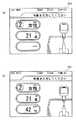
図10は、トレーニング内容選択画面を示す。上述のように電子KEY、又はテンキーによる個人情報の入力によって個人認証されると、例えば、図10(a)に示すように、「トレーニングモードを選択してください」などとメッセージが表示されたトレーニングメニュー選択画面がモニタ画面721に表示される(ステップST15)。トレーニングメニュー選択画面から、例えば、個人のペースでトレーニングできるレッスンモード(1番)、又はスピーカ73からのリズム(リズム音楽)などに合わせてエクササイズできるダンスモード(2番)が選択できる。1番あるいは2番のトレーニングモードを選択すると(ステップST17、ステップST25)、例えば、図10(b)に示すように、「コースを選択してください」などとメッセージが表示されたコース選択画面が表示される。レッスンメニュー選択画面には、例えば、初級(1番)、中級(2番)、及び上級(3番)の選択コースが表示されるので、これらの中から好みのコース(各モードにおけるレッスンメニュー)が選択できる。次に、入力した内容を確認し(ステップST19、ステップST27)、訂正する場合、ステップST15に戻る。この内容で良ければトレーニングを開始する(ステップST21、ステップST29)。
【0050】
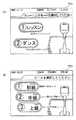
ここで、図11、12に、トレーニング時にモニタ画面721に表示される各トレーニングモード画面を示す。図11は、レッスンモードを選択した場合のレッスン画面の一例を示している。まず、レッスンには、トレーニング時の手摺り部60の掴まり方などによって幾つかの種類に分かれており(例えば、片手だけで掴まって行う、又は、腕を狭めた状態で掴まって行うトレーニング)、この各種類のレッスンをミニレッスンという。レッスン画面の下部には、各ミニレッスンが識別できるような代表的な動作姿勢(ポーズ)が表現された、ミニレッスンシンボルキャラが表示される。レッスン画面の中心部付近には、現在行われているミニレッスンの動作を確認するためのムービー(動作確認ムービー)が表示される。すなわち、ミニレッスンシンボルキャラが、各ミニレッスンに合わせた動きとともに表示される。この動作確認ムービー表示部の左横には、現在行われているミニレッスンの名称(技名)が表示されている。また、画面左側には、次のレッスンの動作を確認するためのムービー(次動作確認ミニムービー)が表示されている。画面中央部には、各ミニレッスンにおける反復回数(現在の回数/規定回数)が表示されている(回数表示部)。画面上部には、「次に両ヒザを曲げましょう」などとトレーニング動作を説明するメッセージが順に表示される。また、画面右側には、トレーニングの際、意識を集中して欲しい筋肉部位などが識別可能な表示態様、例えば人体図(人体筋肉図)の一部を色違いで表示している。さらに、画面上部には、トレーニング開始時からカウントされた反復回数、消費カロリー(kcal)及びトレーニング開始からの経過時間などが表示される。
【0051】
図12は、上記ダンスモードを選択した場合のダンス画面の一例を示す。図12は、図11の画面構成と同様であり、上記レッスンモードと同様に画面表示を行える。ただし、図12のダンス画面には人体図や回数表示部が表示されていないが、これらを表示してもよい。本ダンスモード(ダンス画面)では、曲(リズム音楽)によってミニレッスンが進行するため、上記動作確認ムービーの各ミニレッスン画面の切り替えを意識させるために、この動作確認ムービー画面上に大きく目立つように、例えば、「3、2、1、0」などとカウント表示を行ってもよい。
【0052】
図11、12の各トレーニングモード画面の指示内容に従って全てのトレーニング(ミニレッスン)を終了した後、あるいは、途中でトレーニングを終了したい場合、コントローラ80、又は腕に嵌めたトランスポンダTP付きリングなどに設けられた終了ボタンを押し、終了信号を制御部100に送信する(ステップST23、ステップST31)。この終了信号を受信した表示処理部100は、画像生成部1001や音声制御部1002に、トレーニングの終了動作をさせる。すなわち、モニタ画面721に「トレーニングを終了します」などとメッセージを表示させる。また、制御部100は、演算部1005にトレーニング結果の集計を行うよう指示する。例えば、演算部1005では、上述のように、タイマ1003やセンサ検出信号処理部1004からの情報に基づいて、スライド運動(ツイスト運動)の反復回数、トレーニング開始から終了までの経過時間(所要時間)、操作タイミングが一致していた回数、又はトータル消費カロリーなどを集計する。そして、これらの結果をモニタ画面721に表示する(ステップST33)。
【0053】
なお、終了動作を行う前のトレーニング(ミニレッスン)時における(ステップST21、ステップST29)、図11、12の各モード画面に表示されるような、反復回数(現在の回数/規定回数)、消費カロリー及びトレーニング開始からの経過時間なども、同様に制御部100によって表示制御される。
【0054】
このように、トレーニング装置1は、モードやコースなどのトレーニングメニューが選択でき、また、そのトレーニング結果がモニタ72に表示されるので、トレーニング目的を明確にできる同時に、運動方法(トレーニング装置1の使用方法)、あるいは、トレーニングを効果的に行うための理解を高められるようになる。さらに、モニタ72に表示される内容(コンテンツ)によってトレーニング表示以外のゲームや、テレビ等の娯楽映像を表示させ、単調、かつ退屈になりがちなトレーニング時間を楽しく過ごせるようにすることもできる。
【0055】
図13は、トレーニング装置の変形態様を示す上面概略構成図である。この変形態様に係る構成部1′は、基台10′、スライド基部20′、足置き部30′、連結部40′を備える。基台10′は左右に伸びる所要幅及び所要厚みを有する板状体で、内部には所要幅を有し、長手方向に亘る長孔11′が切欠かれている。スライド基部20′は円柱状体であり、長孔11′の幅寸法に対応する直径を有し、この長孔11′に遊嵌されるものである。円柱状体20′の上面にはこの円柱状体20′を回動中心が一致するように、所定形状例えば円板状をなす足置き部30′が取り付けられている。円柱状体20′と足置き部30′は供回り構造でも、相対回転可能な構造でもよい。足置き部30′の側部適所には中心から放射状に延設される所要幅を有するアーム41′が設けられている。基台10′の中心前方位置には所要径を有する円柱状の揺動軸42′が取り付けられている。アーム41′の内部には長手方向に亘って揺動軸42′に対応する幅を有する長孔411′が切欠かれている。揺動軸42′はこの長孔411′に嵌合されている。なお、付勢部は、前記実施形態と同様に基部10′とスライド基部20′間に係合させて張設しておけばよい。この構成によっても、スライド運動と回転動作とを連動して行わせることが可能となる。
【0056】
なお、本発明は以下の変形態様を採用することができる。
(1)足置き部30の形状は、四角形状の他、円形状や、四角以外の多角形状であってもよい。したがって、例えば、足置き部30をサーフボード、スノーボードあるいはスキー板の形状を模したものとしてもよい。
【0057】
(2)スライドシャフト14及びロッド41は直線形状でなくともよく、一部あるいは全体に亘って湾曲部を有していてもよい。また、スライドシャフト14及びロッド41の断面形状は、真円でなくともよく、楕円(偏心円)であってもよいし、長方形や正方形をした多角形であってもよい。また、ロッド41と筒体31とは一体形成されていてもよい。この場合、上コロ21、下コロ22、及びコロ424の周面は可及的に全面で当接する形状に対応して形成されればよい。
【0058】
(3)コロ424の設置位置は、スライド基部20のスライド移動面内でなくともよく、足置き部30の上方に設置されていてもよい。例えば、ロッド41をスライド基部20(足置き部30)の水平面に対して鉛直方向上向きに立設し、垂直面内の揺動運動となるようにして、前後方向の寸法の小型化を図ってもよい。
【0059】
(4)センサ74は、ガイド部70に設けなくともよく、例えば、手摺り部60の適所やコントローラ80に設けてもよい。また、スライド移動により往復運動した回数を計測するために、例えば、近接センサや機械的スイッチで構成する位置センサを、基台10の左右適所に取り付けておき、スライド基部20の存在を検出し、その検出回数をカウントすることで、往復回数を計数するようにしてもよい。あるいは、揺動アーム支持部42適所に、ロッド41の揺動を検出する位置センサを設けて、その揺動回数を計数するようにしてもよい。
【0060】
(5)圧力センサを足置き部30上、あるいは足置き部30内部乃至は下面に取り付け、足置き部30上にかかる荷重を検出することで足置き部30上にプレイヤが乗ったことを検知するようにしてもよい。
【0061】
(6)モニタ72は、基台10側と別体とせず、一体で構成してもよい。このようにすれば、コントローラ80との信号線の配線が容易となる。
【0062】
(7)トランスポンダTP付きリングなどの代わりに、個人情報が記録されたカードなどを用い、コントローラ80などにカード情報読み取り部(カード挿入部)を設け、ここにカードを差し込むなどすることで個人認証を行ってもよい。
【0063】
(8)モニタ72表面に透明体からなる公知のタッチパネルセンサを貼り、制御部100内に、画面上の位置とタッチパネルセンサの位置との座標を関連付けする手段と、タッチ位置の検出座標から画面上に表示した各ボタンのいずれかを特定する手段を設ける態様としてもよい。これによれば、コントローラ操作がその分、容易となる。
【0064】
【発明の効果】
請求項1記載の発明によれば、足踏み動作などを必要とせずスライド運動とツイスト運動とを連動して行え、体幹部を効果的にトレーニングできるトレーニング装置を提供することができる。
【0065】
請求項2記載の発明によれば、足置き台の回転運動を、揺動アームを揺動運動の腕として、かつ揺動アーム支持部を回転中心(軸)としてスライド回転と連動して行わせることができる。
【0066】
請求項3記載の発明によれば、揺動アームを簡易な構造とすることができる。また、揺動アームをローラ対の挟持位置で揺動中心とし、かつ摺動可能にすることで揺動動作を容易に実現できる。
【0067】
請求項4記載の発明によれば、スライド基部を安定してスライド移動させることができる。
【0068】
請求項5記載の発明によれば、スライド基部のガイドレールからの離脱を効果的に防止できる。
【0069】
請求項6記載の発明によれば、下側のローラの軸を、水平な場合に比して高い位置でスライド基部に軸支できるので、その分、スライド基部の高さ寸法を短縮でき、したがってスライド基部をコンパクト化できる。
【0070】
請求項7記載の発明によれば、付勢手段を簡易な構造で実現できる。
【0071】
請求項8記載の発明によれば、手摺り部を掴むことにより、足置き台を両足で踏ん張ってスライド始動を容易にでき、また、スライド運動と回転運動とを同時に行いながらも体のバランスを取り易くすることができる。
【0072】
請求項9記載の発明によれば、モニタ画面を介してトレーニングガイド用の画像を提供できる。
【0073】
請求項10記載の発明によれば、コントローラを介してプレイヤに所望のトレーニングガイドを提供できる。
【0074】
請求項11記載の発明によれば、足置き台に乗った状態でコントローラの操作を可能にできる。
【図面の簡単な説明】
【図1】本発明に係るトレーニング装置の一実施形態を示す外観斜視図である。
【図2】図1のカバー類を取り外した状態での構造を示す図で、(a)は後方斜視図、(b)は前方斜視図である。
【図3】図2の平面図で、(a)は足置き部がスライドしていない状態を示す図、(b)は足置き部がスライドしている状態を示す図である。
【図4】基台とスライド基部との連結構造を示す図である。
【図5】足置き部と連結機構部との連結構造を説明する下方から見た図である。
【図6】トレーニング動作の一例を示す図である。
【図7】トレーニング装置におけるトレーニングガイドを行う制御系を示すブロック図である。
【図8】モニタへの表示処理を示すフローチャートである。
【図9】モニタ画面に表示される個人情報入力画面で、(a)は年齢入力画面、(b)は体重入力画面を示している。
【図10】トレーニング内容選択画面で、(a)はトレーニングメニュー選択画面を、(b)はコース選択画面を示している。
【図11】レッスンモードを選択した場合のレッスン画面の一例を示す図である。
【図12】ダンスモードを選択した場合のダンス画面の一例を示す図である。
【図13】トレーニング装置の変形態様を示す上面概略構成図である。
【図14】従来のトレーニング装置で、(a)は斜視図を、(b)は平面図を示している。
【図15】従来の他のトレーニング装置の斜視図を示している。
【符号の説明】
1 トレーニング装置
10 基台
11 外枠
12 渡し用梁
13 中央梁
14 スライドシャフト(ガイドレール)
15 ストッパ
20 スライド基部
21 上コロ(ローラ対、上側のローラ)
22 下コロ(ローラ対、下側のローラ)
23 円柱体
30 足置き部(足置き台)
31 筒体
40 連結機構部(連結手段)
41 ロッド(揺動アーム)
42 揺動アーム支持部
423 回動部材
424 コロ(ローラ対)
50 付勢部(付勢手段)
51,52 スプリング
60 手摺り部
70 ガイド部
71 本体部
72 モニタ
73 スピーカ
74 センサ
80 コントローラ
81 テンキーユニット
82 受信部
100 制御部
103 データ記憶部
1001 画像生成部
1002 音声制御部
1003 タイマ
1004 検出信号処理部
1005 演算部
1006 通信制御部
TP トランスポンダ[0001]
TECHNICAL FIELD OF THE INVENTION
The present invention relates to a training device that performs a slide exercise and a twist exercise at the same time.
[0002]
[Prior art]
2. Description of the Related Art Conventionally, a training device capable of performing a slide exercise or a twist exercise has been known. In this device, as shown in FIGS. 14A and 14B, the
[0003]
As a conventional device, as shown in FIG. 15, a
[0004]
[Problems to be solved by the invention]
In everyday life and sports scenes, there are many opportunities to move the body in an unstable position (posture). When trying to balance the body in this unstable state, it is often the case that so-called torso, such as the abdominal muscles and the back muscles, is exerted not only on the limbs (limbs). Therefore, when performing body training, it is important to perform not only limb training but also trunk training.
[0005]
However, in the above-mentioned conventional technique, since the left and right footrests individually move and rotate, both the sliding motion and the twisting motion are performed separately by each foot.
[0006]
Also, as a conventional device, a device in which the left and right footrests move in cooperation with each other is known, but since this device can be moved simply by changing the direction of the force applied to the foot, It is difficult to expect systemic exercise effects. In addition, since it is only necessary to pay attention to the feet during exercise, the transition to the next exercise is easy, and there is a problem that the trunk cannot be effectively trained.
[0007]
The present invention has been made in view of the above problems, and has as its object to provide a training apparatus that can perform a slide exercise and a twist exercise in conjunction with each other without requiring a stepping operation or the like, and can effectively train the trunk. Is to provide.
[0008]
[Means for Solving the Problems]
The invention according to
[0009]
According to the above configuration, when the slide base is slid in the left-right direction along the guide rail, the footrest on the slide base is connected to the slide base by an angle corresponding to the slide movement distance due to the provision of the connecting means. Rotate against That is, when the slide base slides, the footrest swings in the slide movement direction. In addition, since the biasing means for generating the restoring force is provided, the footrest slid to the left and right is automatically returned to the neutral position in the longitudinal center of the guide rail, and When the slide is moved, an appropriate load is generated, which is preferable for training. The player can simultaneously perform the slide exercise and the twist exercise without disturbing the balance of the body with both feet on the footrest, and the trunk is effectively trained.
[0010]
According to a second aspect of the present invention, in the training apparatus according to the first aspect, the connecting means includes: a swing arm having one end connected to the footrest; A swing arm support provided on the base for movably supporting the base. According to this configuration, the rotary motion of the footrest is performed in conjunction with the slide motion with the swing arm as the swing arm and the swing arm support as the center of rotation (axis).
[0011]
According to a third aspect of the present invention, in the training apparatus according to the second aspect, the swing arm is formed of a rod-shaped body, and the swing arm support portion includes a pair of rollers for holding the rod-shaped body. According to this configuration, the swing arm has a simple structure. Further, the swinging operation is realized by the swinging arm being the center of swinging and sliding at the sandwiching position of the roller pair.
[0012]
According to a fourth aspect of the present invention, in the training apparatus according to any one of the first to third aspects, two guide rails are arranged in parallel, and each of the slide bases has a respective guide rail at both ends in the front-rear direction. It is characterized by being sandwiched. According to this configuration, the slide base is slidably moved in a stable manner.
[0013]
According to a fifth aspect of the present invention, in the training apparatus according to any one of the first to fourth aspects, the slide base includes a pair of rollers that sandwich the guide rail from above and below. According to this configuration, the slide base is prevented from coming off the guide rail.
[0014]
According to a sixth aspect of the present invention, in the training apparatus according to the fifth aspect, the shaft of the upper roller of the pair of rollers that sandwiches the guide rail from above and below is horizontal, and the axis of the lower roller is inclined. It is characterized by being arranged. According to this configuration, the shaft of the lower roller can be pivotally supported on the slide base at a higher position than in the case of being horizontal, so that the height dimension of the slide base is shortened accordingly, and therefore the slide base is Can be made more compact.
[0015]
According to a seventh aspect of the present invention, in the training apparatus according to any one of the first to sixth aspects, the biasing means is a spring stretched between the slide base and the base. . According to this configuration, the urging means has a simple structure.
[0016]
According to an eighth aspect of the present invention, in the training apparatus according to any one of the first to seventh aspects, the base is provided with a handrail. According to this configuration, by grasping the handrail portion, it is easy to start the slide by stepping on the footrest with both feet, and it is easy to balance the body while performing the sliding motion and the rotating motion simultaneously.
[0017]
According to a ninth aspect of the present invention, there is provided the training apparatus according to any one of the first to eighth aspects, further comprising a monitor for displaying a training guide image. According to this configuration, an image for a training guide is provided via the monitor screen.
[0018]
According to a tenth aspect of the present invention, there is provided the training apparatus according to the ninth aspect, further comprising a controller for instructing switching of a training guide image displayed on the monitor. According to this configuration, a desired training guide is provided to the player via the controller.
[0019]
An eleventh aspect of the present invention is the training apparatus according to the tenth aspect, wherein the controller is provided in the handrail. According to this configuration, it is possible to operate the controller while riding on the footrest.
[0020]
BEST MODE FOR CARRYING OUT THE INVENTION
FIG. 1 is an external perspective view showing an embodiment of a training device according to the present invention, FIG. 2 is a diagram showing a structure in a state where covers are removed in FIG. 1, (a) is a rear perspective view, 3B is a front perspective view, FIG. 3 is a plan view of FIG. 2, FIG. 3A is a view showing a state where the footrest is not slid, and FIG. 3B is a view showing a state where the footrest is slid. FIG.
[0021]
As shown in FIGS. 1 to 3, the
[0022]
In FIG. 1, the
[0023]
Subsequently, a detailed structure will be described with reference to FIGS. FIG. 4 is a diagram showing a connection structure between the base 10 and the
[0024]
The
[0025]
The basic structure of the
[0026]
The
[0027]
The number of pairs of rollers consisting of the
[0028]
The
[0029]
The
[0030]
The
[0031]
The urging
[0032]
In FIG. 3 described above, the biasing
[0033]
The
[0034]
As shown in FIG. 1, the
[0035]
The
[0036]
The operation of the above configuration will now be described.
[0037]
When the
[0038]
As described above, by rotating the
[0039]
Further, when returning to the center position from the state of sliding movement, continuous movement can be easily performed by using the urging force of the urging
[0040]
Further, the force of pushing the slide base 20 (footrest 30) in the lateral (left / right) direction when the slide base 20 (the footrest 30) is slid is increased as the position on which the
[0041]
FIG. 7 is a block diagram illustrating a control system that performs a training guide in the
[0042]
The
[0043]
The
[0044]
The
[0045]
FIG. 8 is a flowchart showing the display processing on the monitor. Normally, a series of images displayed during training are displayed on the
[0046]
Note that the electronic key input can be performed only at the time when a message such as “Please hold the electronic key over the numeric keypad” as described above is displayed. Even if the electronic key is mistakenly held over the
[0047]
It is confirmed whether or not the electronic key is present (step ST7). If the player P does not have the electronic key, a personal data input screen is displayed, and personal information is input from the ten
[0048]
FIG. 9 shows a personal information (personal data) input screen displayed on the
[0049]
FIG. 10 shows a training content selection screen. When the personal authentication is performed by inputting the personal information using the electronic key or the numeric keypad as described above, for example, as shown in FIG. 10A, the training in which the message “Please select the training mode” is displayed. A menu selection screen is displayed on monitor screen 721 (step ST15). From the training menu selection screen, for example, a lesson mode (No. 1) in which training can be performed at an individual pace or a dance mode (No. 2) in which exercise can be performed in accordance with rhythm (rhythm music) from the
[0050]
Here, FIGS. 11 and 12 show respective training mode screens displayed on the
[0051]
FIG. 12 shows an example of the dance screen when the dance mode is selected. FIG. 12 is the same as the screen configuration of FIG. 11, and the screen can be displayed in the same manner as in the lesson mode. Although the human body figure and the number-of-times display unit are not displayed on the dance screen of FIG. 12, these may be displayed. In this dance mode (dance screen), the mini-lesson progresses according to the tune (rhythm music). For example, a count display such as “3, 2, 1, 0” may be performed.
[0052]
When all training (mini-lesson) is completed according to the instruction contents of each training mode screen of FIGS. 11 and 12 or when training is to be completed in the middle, provided on the
[0053]
Note that, during the training (mini-lesson) before performing the end operation (step ST21, step ST29), the number of repetitions (current number / specified number) and consumption as displayed on the mode screens of FIGS. The display of the calories, the elapsed time from the start of the training, and the like are similarly controlled by the
[0054]
As described above, the
[0055]
FIG. 13 is a schematic top view showing a modification of the training apparatus. The component 1 'according to this modification includes a base 10', a slide base 20 ', a footrest 30', and a connecting portion 40 '. The base 10 'is a plate-like body having a required width and a required thickness extending left and right. The base 10' has a required width inside, and has a long hole 11 'extending in the longitudinal direction. The slide base 20 'is a columnar body, has a diameter corresponding to the width of the elongated hole 11', and is loosely fitted in the elongated hole 11 '. A footrest 30 'having a predetermined shape, for example, a disk shape, is attached to the upper surface of the columnar body 20' so that the center of rotation of the columnar body 20 'coincides. The
[0056]
The present invention can adopt the following modified embodiments.
(1) The shape of the
[0057]
(2) The
[0058]
(3) The installation position of the
[0059]
(4) The
[0060]
(5) A pressure sensor is mounted on the
[0061]
(6) The
[0062]
(7) Instead of a ring with a transponder TP or the like, a card or the like in which personal information is recorded is used. May be performed.
[0063]
(8) A publicly-known touch panel sensor made of a transparent body is attached to the surface of the
[0064]
【The invention's effect】
According to the first aspect of the present invention, it is possible to provide a training apparatus capable of performing a slide exercise and a twist exercise in conjunction with each other without requiring a stepping operation or the like and effectively training the trunk.
[0065]
According to the second aspect of the present invention, the rotary motion of the footrest is performed in conjunction with the slide rotation using the swing arm as the swing motion arm and the swing arm support portion as the rotation center (axis). be able to.
[0066]
According to the third aspect of the present invention, the swing arm can have a simple structure. In addition, the swing operation can be easily realized by making the swing arm the swing center at the sandwiching position of the roller pair and making the swing arm slidable.
[0067]
According to the fourth aspect of the present invention, the slide base can be slid and moved stably.
[0068]
According to the fifth aspect of the present invention, the detachment of the slide base from the guide rail can be effectively prevented.
[0069]
According to the invention of claim 6, since the shaft of the lower roller can be supported on the slide base at a higher position than in the case of being horizontal, the height dimension of the slide base can be shortened accordingly, and therefore, The slide base can be made compact.
[0070]
According to the seventh aspect of the present invention, the urging means can be realized with a simple structure.
[0071]
According to the invention as set forth in claim 8, by grasping the handrail portion, it is possible to easily start the slide by stepping on the footrest with both feet, and to balance the body while simultaneously performing the slide movement and the rotation movement. It can be easily taken.
[0072]
According to the ninth aspect, an image for a training guide can be provided via the monitor screen.
[0073]
According to the tenth aspect, a desired training guide can be provided to the player via the controller.
[0074]
According to the eleventh aspect of the present invention, it is possible to operate the controller while riding on the footrest.
[Brief description of the drawings]
FIG. 1 is an external perspective view showing an embodiment of a training device according to the present invention.
FIGS. 2A and 2B are diagrams showing a structure in a state in which covers of FIG. 1 are removed, wherein FIG. 2A is a rear perspective view, and FIG.
FIGS. 3A and 3B are plan views of FIG. 2, wherein FIG. 3A is a diagram illustrating a state where the footrest is not slid, and FIG. 3B is a diagram illustrating a state where the footrest is slid.
FIG. 4 is a diagram showing a connection structure between a base and a slide base.
FIG. 5 is a diagram illustrating a connection structure between a footrest unit and a connection mechanism unit as viewed from below.
FIG. 6 is a diagram illustrating an example of a training operation.
FIG. 7 is a block diagram showing a control system for performing a training guide in the training device.
FIG. 8 is a flowchart showing display processing on a monitor.
FIG. 9 is a personal information input screen displayed on a monitor screen, wherein (a) shows an age input screen and (b) shows a weight input screen.
FIG. 10 shows a training content selection screen, (a) showing a training menu selection screen, and (b) showing a course selection screen.
FIG. 11 is a diagram showing an example of a lesson screen when a lesson mode is selected.
FIG. 12 is a diagram illustrating an example of a dance screen when a dance mode is selected.
FIG. 13 is a schematic top view showing a modification of the training apparatus.
14 (a) is a perspective view and FIG. 14 (b) is a plan view of a conventional training apparatus.
FIG. 15 is a perspective view of another conventional training apparatus.
[Explanation of symbols]
1 Training device
10 bases
11 Outer frame
12 Beam for delivery
13 Central beam
14 Slide shaft (guide rail)
15 Stopper
20 slide base
21 Upper roller (roller pair, upper roller)
22 Lower roller (roller pair, lower roller)
23 cylinder
30 Footrest (footrest)
31 cylinder
40 connection mechanism (connection means)
41 Rod (Swinging arm)
42 swing arm support
423 Rotating member
424 rollers (roller pair)
50 urging unit (urging means)
51,52 Spring
60 Handrail
70 Guide
71 Main unit
72 monitors
73 speaker
74 sensor
80 Controller
81 Numeric keypad unit
82 Receiver
100 control unit
103 Data storage unit
1001 Image generation unit
1002 Voice control unit
1003 timer
1004 detection signal processing unit
1005 Operation unit
1006 Communication control unit
TP transponder
Claims (11)
Translated fromJapanesePriority Applications (7)
| Application Number | Priority Date | Filing Date | Title |
|---|---|---|---|
| JP2002267813AJP3535866B2 (en) | 2002-09-13 | 2002-09-13 | Training equipment |
| US10/527,369US7303508B2 (en) | 2002-09-13 | 2003-09-05 | Training equipment |
| EP03795292AEP1550484A4 (en) | 2002-09-13 | 2003-09-05 | Training equipment |
| KR1020057004181AKR100678531B1 (en) | 2002-09-13 | 2003-09-05 | Training device |
| AU2003261949AAU2003261949A1 (en) | 2002-09-13 | 2003-09-05 | Training equipment |
| PCT/JP2003/011331WO2004024241A1 (en) | 2002-09-13 | 2003-09-05 | Training equipment |
| CNB038215942ACN100428968C (en) | 2002-09-13 | 2003-09-05 | Training equipment |
Applications Claiming Priority (1)
| Application Number | Priority Date | Filing Date | Title |
|---|---|---|---|
| JP2002267813AJP3535866B2 (en) | 2002-09-13 | 2002-09-13 | Training equipment |
Publications (2)
| Publication Number | Publication Date |
|---|---|
| JP2004105219Atrue JP2004105219A (en) | 2004-04-08 |
| JP3535866B2 JP3535866B2 (en) | 2004-06-07 |
Family
ID=31986726
Family Applications (1)
| Application Number | Title | Priority Date | Filing Date |
|---|---|---|---|
| JP2002267813AExpired - Fee RelatedJP3535866B2 (en) | 2002-09-13 | 2002-09-13 | Training equipment |
Country Status (7)
| Country | Link |
|---|---|
| US (1) | US7303508B2 (en) |
| EP (1) | EP1550484A4 (en) |
| JP (1) | JP3535866B2 (en) |
| KR (1) | KR100678531B1 (en) |
| CN (1) | CN100428968C (en) |
| AU (1) | AU2003261949A1 (en) |
| WO (1) | WO2004024241A1 (en) |
Cited By (7)
| Publication number | Priority date | Publication date | Assignee | Title |
|---|---|---|---|---|
| JP2006262964A (en)* | 2005-03-22 | 2006-10-05 | Matsushita Electric Works Ltd | Massage machine |
| JP2010046198A (en)* | 2008-08-20 | 2010-03-04 | Grand Works Japan Inc | Training equipment |
| JP2012523287A (en)* | 2009-04-09 | 2012-10-04 | フィットワークス, エルエルシー | Sliding abdominal exercise device |
| JP2017038756A (en)* | 2015-08-19 | 2017-02-23 | 智一 丸山 | Exercise support device and exercise support program |
| JP2019205594A (en)* | 2018-05-29 | 2019-12-05 | 株式会社コナミスポーツライフ | Exercise instruction device, program, training system and exercise apparatus |
| JP2020195470A (en)* | 2019-05-31 | 2020-12-10 | アイデス株式会社 | Sliding toy |
| JP7174456B1 (en) | 2021-10-12 | 2022-11-17 | 株式会社コナミアミューズメント | Game system, computer program used therefor, and control method |
Families Citing this family (61)
| Publication number | Priority date | Publication date | Assignee | Title |
|---|---|---|---|---|
| US7614987B2 (en)* | 2004-06-15 | 2009-11-10 | Vincenzo Guadagno | Balance and motion exercise training an conditioning device |
| ITFI20040265A1 (en)* | 2004-12-17 | 2005-03-17 | Enrico Tacconi | DEVICE FOR THE REHABILITATION OF ARTS AND TRUNK |
| US7458924B1 (en)* | 2005-09-08 | 2008-12-02 | Ladd Anderson | Frame for dance platform |
| US7635324B2 (en)* | 2005-10-04 | 2009-12-22 | Anastasios Balis | Extensor muscle based postural rehabilitation systems and methods with integrated multimedia therapy and instructional components |
| USD548291S1 (en)* | 2005-10-25 | 2007-08-07 | Yu Sung Chiang | Slimming machine |
| US20070184953A1 (en)* | 2006-02-09 | 2007-08-09 | Sportkat, Llc | System and method of balance training |
| US20070219065A1 (en)* | 2006-03-13 | 2007-09-20 | Anderson Timothy T | Climber apparatus |
| EP2007485A2 (en)* | 2006-04-14 | 2008-12-31 | Icon Health & Fitness, Inc. | Exercise apparatuses, components for exercise apparatuses and related methods |
| US20080119337A1 (en) | 2006-10-20 | 2008-05-22 | Wilkins Larry C | Exercise device with features for simultaneously working out the upper and lower body |
| WO2008126084A1 (en)* | 2007-04-16 | 2008-10-23 | Haim Hazan | Exercise device for stomach muscles |
| USD580502S1 (en)* | 2007-08-16 | 2008-11-11 | Power Plate North America Inc. | Flip-over element for an exercise apparatus |
| US7666120B2 (en)* | 2007-11-16 | 2010-02-23 | Brunswick Corporation | Exercise apparatus with three dimensional motion |
| US7625317B2 (en)* | 2007-11-16 | 2009-12-01 | Brunswick Corporation | Exercise apparatus with coupled motion mechanism |
| US20090156367A1 (en)* | 2007-12-14 | 2009-06-18 | Z-Man Fishing Products, Inc. | Hand exerciser |
| GB2462680A (en)* | 2008-08-21 | 2010-02-24 | Ludmila Scott | Dance Exercise Apparatus |
| US7927257B2 (en)* | 2008-10-21 | 2011-04-19 | Rakesh Patel | Assisted stair training machine and methods of using |
| US7955240B2 (en)* | 2009-06-12 | 2011-06-07 | Yasser Nadim | Exercise device and method of using same |
| US8057362B2 (en)* | 2009-06-12 | 2011-11-15 | Yasser Nadim | Exercise device and method of using same |
| USD640334S1 (en)* | 2010-03-01 | 2011-06-21 | Morris Aboody | Whole body vibration machine |
| USD624611S1 (en)* | 2010-03-23 | 2010-09-28 | Actervis Gmbh | Vibrating exercise device |
| USD640336S1 (en)* | 2010-06-24 | 2011-06-21 | Morris Aboody | Whole body vibration machine |
| US9339691B2 (en) | 2012-01-05 | 2016-05-17 | Icon Health & Fitness, Inc. | System and method for controlling an exercise device |
| USD694349S1 (en)* | 2012-03-16 | 2013-11-26 | Paul Chen | Balancing exerciser |
| DE202012003092U1 (en) | 2012-03-26 | 2012-04-26 | Oliver Seitz | training device |
| US9999818B2 (en)* | 2012-08-27 | 2018-06-19 | Wahoo Fitness Llc | Bicycle trainer |
| WO2014153158A1 (en) | 2013-03-14 | 2014-09-25 | Icon Health & Fitness, Inc. | Strength training apparatus with flywheel and related methods |
| US20160256737A1 (en)* | 2013-03-25 | 2016-09-08 | Saburo Yoshioka | Low impact exercise machine for improving balance and stable mobility |
| CN105848733B (en) | 2013-12-26 | 2018-02-13 | 爱康保健健身有限公司 | Magnetic resistance mechanism in hawser apparatus |
| US10433612B2 (en) | 2014-03-10 | 2019-10-08 | Icon Health & Fitness, Inc. | Pressure sensor to quantify work |
| WO2015191445A1 (en) | 2014-06-09 | 2015-12-17 | Icon Health & Fitness, Inc. | Cable system incorporated into a treadmill |
| WO2015195965A1 (en) | 2014-06-20 | 2015-12-23 | Icon Health & Fitness, Inc. | Post workout massage device |
| US10258828B2 (en) | 2015-01-16 | 2019-04-16 | Icon Health & Fitness, Inc. | Controls for an exercise device |
| US10391361B2 (en) | 2015-02-27 | 2019-08-27 | Icon Health & Fitness, Inc. | Simulating real-world terrain on an exercise device |
| CN104689548B (en)* | 2015-03-03 | 2017-05-10 | 刘宇平 | Skiing simulation trainer |
| US10245494B1 (en)* | 2015-03-03 | 2019-04-02 | Christopher Lee Gentry | Trick board training apparatus |
| US10537764B2 (en) | 2015-08-07 | 2020-01-21 | Icon Health & Fitness, Inc. | Emergency stop with magnetic brake for an exercise device |
| US10953305B2 (en) | 2015-08-26 | 2021-03-23 | Icon Health & Fitness, Inc. | Strength exercise mechanisms |
| US10625137B2 (en) | 2016-03-18 | 2020-04-21 | Icon Health & Fitness, Inc. | Coordinated displays in an exercise device |
| US10293211B2 (en) | 2016-03-18 | 2019-05-21 | Icon Health & Fitness, Inc. | Coordinated weight selection |
| US10561894B2 (en) | 2016-03-18 | 2020-02-18 | Icon Health & Fitness, Inc. | Treadmill with removable supports |
| US10272317B2 (en) | 2016-03-18 | 2019-04-30 | Icon Health & Fitness, Inc. | Lighted pace feature in a treadmill |
| US10493349B2 (en) | 2016-03-18 | 2019-12-03 | Icon Health & Fitness, Inc. | Display on exercise device |
| US10252109B2 (en) | 2016-05-13 | 2019-04-09 | Icon Health & Fitness, Inc. | Weight platform treadmill |
| US10471299B2 (en) | 2016-07-01 | 2019-11-12 | Icon Health & Fitness, Inc. | Systems and methods for cooling internal exercise equipment components |
| US10441844B2 (en) | 2016-07-01 | 2019-10-15 | Icon Health & Fitness, Inc. | Cooling systems and methods for exercise equipment |
| US10671705B2 (en) | 2016-09-28 | 2020-06-02 | Icon Health & Fitness, Inc. | Customizing recipe recommendations |
| US10500473B2 (en) | 2016-10-10 | 2019-12-10 | Icon Health & Fitness, Inc. | Console positioning |
| US10376736B2 (en) | 2016-10-12 | 2019-08-13 | Icon Health & Fitness, Inc. | Cooling an exercise device during a dive motor runway condition |
| US10661114B2 (en) | 2016-11-01 | 2020-05-26 | Icon Health & Fitness, Inc. | Body weight lift mechanism on treadmill |
| TWI646997B (en) | 2016-11-01 | 2019-01-11 | 美商愛康運動與健康公司 | Distance sensor for console positioning |
| TWI637770B (en) | 2016-11-01 | 2018-10-11 | 美商愛康運動與健康公司 | Drop-in pivot configuration for stationary bikes |
| US10625114B2 (en) | 2016-11-01 | 2020-04-21 | Icon Health & Fitness, Inc. | Elliptical and stationary bicycle apparatus including row functionality |
| CN106422265B (en)* | 2016-11-15 | 2019-06-18 | 运达体育管理(北京)有限公司 | Skis ranging calibration system and simulation skiing instrument |
| TWI680782B (en) | 2016-12-05 | 2020-01-01 | 美商愛康運動與健康公司 | Offsetting treadmill deck weight during operation |
| US10702736B2 (en) | 2017-01-14 | 2020-07-07 | Icon Health & Fitness, Inc. | Exercise cycle |
| US9987518B1 (en) | 2017-01-30 | 2018-06-05 | Louis John Stack | Balance board |
| EP3579934B1 (en)* | 2017-02-13 | 2024-08-07 | Woodway USA, Inc. | Console assembly for a treadmill |
| US11451108B2 (en) | 2017-08-16 | 2022-09-20 | Ifit Inc. | Systems and methods for axial impact resistance in electric motors |
| US10729965B2 (en) | 2017-12-22 | 2020-08-04 | Icon Health & Fitness, Inc. | Audible belt guide in a treadmill |
| CN108671514B (en)* | 2018-05-21 | 2020-04-28 | 牡丹江师范学院 | Auxiliary device for university student skiing training |
| CN115193003B (en)* | 2022-07-21 | 2023-08-15 | 东北石油大学 | An aerobics body training action correction device |
Family Cites Families (15)
| Publication number | Priority date | Publication date | Assignee | Title |
|---|---|---|---|---|
| US3364875A (en)* | 1965-01-07 | 1968-01-23 | Bilaisis Viktoras | Training device for teaching the art of sking |
| JPS432391Y1 (en)* | 1965-06-24 | 1968-01-31 | ||
| CH468836A (en)* | 1968-05-30 | 1969-02-28 | Schuerch Ernst | Exercise device |
| US4607839A (en)* | 1983-03-04 | 1986-08-26 | Knudson Mark M | Snow ski machine |
| FR2577814A1 (en)* | 1985-02-28 | 1986-08-29 | Riccobene Renee | Apparatus intended for training skiers |
| JPH0239492Y2 (en)* | 1985-10-25 | 1990-10-23 | ||
| JPS6374155A (en) | 1986-09-18 | 1988-04-04 | Sankyo Seiki Mfg Co Ltd | Magnetic recording and reproducing device |
| JPS6374155U (en)* | 1986-10-31 | 1988-05-18 | ||
| US6569064B1 (en)* | 2000-03-22 | 2003-05-27 | R. Joel Loane | Ski exercising apparatus |
| JPH04506464A (en)* | 1989-01-26 | 1992-11-12 | スキー ジャイブ リミッテド | exercise equipment |
| US5078389A (en)* | 1991-07-19 | 1992-01-07 | David Chen | Exercise machine with three exercise modes |
| US5209711A (en)* | 1992-03-30 | 1993-05-11 | Nick Scrima | Leg stretching machine |
| US5328427A (en)* | 1993-11-15 | 1994-07-12 | Sleamaker Robert H | Skating/skiing simulator with ergometric input-responsive resistance |
| JP2001070473A (en)* | 1999-09-09 | 2001-03-21 | Sekisui House Ltd | Generating and displaying CG images |
| US6786850B2 (en)* | 2000-10-04 | 2004-09-07 | Skatestrider Inc. | Exercise apparatus for simulating skating movement |
- 2002
- 2002-09-13JPJP2002267813Apatent/JP3535866B2/ennot_activeExpired - Fee Related
- 2003
- 2003-09-05AUAU2003261949Apatent/AU2003261949A1/ennot_activeAbandoned
- 2003-09-05EPEP03795292Apatent/EP1550484A4/ennot_activeWithdrawn
- 2003-09-05WOPCT/JP2003/011331patent/WO2004024241A1/enactiveApplication Filing
- 2003-09-05KRKR1020057004181Apatent/KR100678531B1/ennot_activeExpired - Fee Related
- 2003-09-05CNCNB038215942Apatent/CN100428968C/ennot_activeExpired - Fee Related
- 2003-09-05USUS10/527,369patent/US7303508B2/ennot_activeExpired - Fee Related
Cited By (12)
| Publication number | Priority date | Publication date | Assignee | Title |
|---|---|---|---|---|
| JP2006262964A (en)* | 2005-03-22 | 2006-10-05 | Matsushita Electric Works Ltd | Massage machine |
| JP2010046198A (en)* | 2008-08-20 | 2010-03-04 | Grand Works Japan Inc | Training equipment |
| JP2012523287A (en)* | 2009-04-09 | 2012-10-04 | フィットワークス, エルエルシー | Sliding abdominal exercise device |
| JP2017038756A (en)* | 2015-08-19 | 2017-02-23 | 智一 丸山 | Exercise support device and exercise support program |
| JP2019205594A (en)* | 2018-05-29 | 2019-12-05 | 株式会社コナミスポーツライフ | Exercise instruction device, program, training system and exercise apparatus |
| JP2020195470A (en)* | 2019-05-31 | 2020-12-10 | アイデス株式会社 | Sliding toy |
| JP7255856B2 (en) | 2019-05-31 | 2023-04-11 | アイデス株式会社 | slide playground equipment |
| JP7174456B1 (en) | 2021-10-12 | 2022-11-17 | 株式会社コナミアミューズメント | Game system, computer program used therefor, and control method |
| WO2023063120A1 (en)* | 2021-10-12 | 2023-04-20 | 株式会社コナミアミューズメント | Game system, computer program used therein, and control method |
| JP2023058005A (en)* | 2021-10-12 | 2023-04-24 | 株式会社コナミアミューズメント | Game system, computer program used therefor, and control method |
| JP2023057672A (en)* | 2021-10-12 | 2023-04-24 | 株式会社コナミアミューズメント | Game system, computer program used therefor, and control method |
| JP7429062B2 (en) | 2021-10-12 | 2024-02-07 | 株式会社コナミアミューズメント | Game system, computer program used therefor, and control method |
Also Published As
| Publication number | Publication date |
|---|---|
| CN1681562A (en) | 2005-10-12 |
| KR100678531B1 (en) | 2007-02-05 |
| WO2004024241A1 (en) | 2004-03-25 |
| US20060009329A1 (en) | 2006-01-12 |
| CN100428968C (en) | 2008-10-29 |
| EP1550484A4 (en) | 2007-12-12 |
| EP1550484A1 (en) | 2005-07-06 |
| US7303508B2 (en) | 2007-12-04 |
| JP3535866B2 (en) | 2004-06-07 |
| KR20050053647A (en) | 2005-06-08 |
| AU2003261949A1 (en) | 2004-04-30 |
Similar Documents
| Publication | Publication Date | Title |
|---|---|---|
| JP3535866B2 (en) | Training equipment | |
| US7022048B1 (en) | Video fitness machine | |
| US8241186B2 (en) | Interactive exercise devices | |
| US20070123390A1 (en) | Exercise equipment with interactive gaming component | |
| US6536770B1 (en) | Intelligent basketball game assembly | |
| US5785631A (en) | Exercise device | |
| US9039576B2 (en) | Curved track simulation device | |
| US8118718B2 (en) | Abdominal exercise training device | |
| JP3742370B2 (en) | Training equipment | |
| US20050209066A1 (en) | Martial Arts Exercise Device and Method | |
| JP2007307284A (en) | Controller holder with sensor | |
| JP2006136694A (en) | Portable game holder | |
| EP4106889B1 (en) | Camera equipped cycle and coordinated punch exercise device and methods | |
| CN203989684U (en) | A ski simulation system | |
| WO2014196866A1 (en) | An apparatus for multipurpose training and exercise | |
| EP2252378A2 (en) | Interactive exercising system | |
| KR20150123574A (en) | Elderly balanced movement system and control method | |
| WO2008053591A1 (en) | Exercise supporting device, and detecting device | |
| JP2007020977A (en) | Exercise assisting apparatus and exercise instrument | |
| KR101847886B1 (en) | Method and apparatus for core exercise | |
| JP3263039B2 (en) | Exercise equipment | |
| HK1075851A (en) | Training equipment | |
| CN1398654A (en) | Speech and music interactive fun device for sports equipment | |
| JPH10216285A (en) | Form learning mentality reinforcing device and mentality reinforcing device | |
| US20240316410A1 (en) | Exercise apparatus with control interfaces on handles |
Legal Events
| Date | Code | Title | Description |
|---|---|---|---|
| A521 | Request for written amendment filed | Free format text:JAPANESE INTERMEDIATE CODE: A523 Effective date:20040107 | |
| TRDD | Decision of grant or rejection written | ||
| A01 | Written decision to grant a patent or to grant a registration (utility model) | Free format text:JAPANESE INTERMEDIATE CODE: A01 Effective date:20040309 | |
| A61 | First payment of annual fees (during grant procedure) | Free format text:JAPANESE INTERMEDIATE CODE: A61 Effective date:20040312 | |
| R150 | Certificate of patent or registration of utility model | Free format text:JAPANESE INTERMEDIATE CODE: R150 | |
| R250 | Receipt of annual fees | Free format text:JAPANESE INTERMEDIATE CODE: R250 | |
| FPAY | Renewal fee payment (event date is renewal date of database) | Free format text:PAYMENT UNTIL: 20090319 Year of fee payment:5 | |
| FPAY | Renewal fee payment (event date is renewal date of database) | Free format text:PAYMENT UNTIL: 20100319 Year of fee payment:6 | |
| FPAY | Renewal fee payment (event date is renewal date of database) | Free format text:PAYMENT UNTIL: 20110319 Year of fee payment:7 | |
| FPAY | Renewal fee payment (event date is renewal date of database) | Free format text:PAYMENT UNTIL: 20130319 Year of fee payment:9 | |
| FPAY | Renewal fee payment (event date is renewal date of database) | Free format text:PAYMENT UNTIL: 20130319 Year of fee payment:9 | |
| FPAY | Renewal fee payment (event date is renewal date of database) | Free format text:PAYMENT UNTIL: 20140319 Year of fee payment:10 | |
| R250 | Receipt of annual fees | Free format text:JAPANESE INTERMEDIATE CODE: R250 | |
| LAPS | Cancellation because of no payment of annual fees |