JP2004102300A - Method and machine for automatically vending photograph sticker - Google Patents
Method and machine for automatically vending photograph stickerDownload PDFInfo
- Publication number
- JP2004102300A JP2004102300AJP2003347017AJP2003347017AJP2004102300AJP 2004102300 AJP2004102300 AJP 2004102300AJP 2003347017 AJP2003347017 AJP 2003347017AJP 2003347017 AJP2003347017 AJP 2003347017AJP 2004102300 AJP2004102300 AJP 2004102300A
- Authority
- JP
- Japan
- Prior art keywords
- image
- imaging
- strobe lighting
- ceiling
- subject
- Prior art date
- Legal status (The legal status is an assumption and is not a legal conclusion. Google has not performed a legal analysis and makes no representation as to the accuracy of the status listed.)
- Pending
Links
- 238000000034methodMethods0.000titleclaimsabstractdescription61
- 238000003384imaging methodMethods0.000claimsabstractdescription71
- 238000005286illuminationMethods0.000claimsdescription29
- 238000009434installationMethods0.000claimsdescription3
- 230000000694effectsEffects0.000abstractdescription8
- 238000009792diffusion processMethods0.000description17
- 238000010586diagramMethods0.000description8
- 230000005236sound signalEffects0.000description5
- 230000012447hatchingEffects0.000description3
- 238000003780insertionMethods0.000description3
- 230000037431insertionEffects0.000description3
- BQCADISMDOOEFD-UHFFFAOYSA-NSilverChemical compound[Ag]BQCADISMDOOEFD-UHFFFAOYSA-N0.000description2
- 238000004891communicationMethods0.000description2
- 239000000463materialSubstances0.000description2
- 239000003973paintSubstances0.000description2
- 229910052709silverInorganic materials0.000description2
- 239000004332silverSubstances0.000description2
- 241000238370SepiaSpecies0.000description1
- 238000007599dischargingMethods0.000description1
- 230000003340mental effectEffects0.000description1
- 239000000203mixtureSubstances0.000description1
- 238000010422paintingMethods0.000description1
- 238000007747platingMethods0.000description1
Images


Landscapes
- Stroboscope Apparatuses (AREA)
- Cameras Adapted For Combination With Other Photographic Or Optical Apparatuses (AREA)
Abstract
Description
Translated fromJapaneseこの発明は、例えばゲームセンター等のアミューズメント施設、遊園地、テーマパーク、旅館、観光施設等の施設に設置され、被写体を照明してデジタルカメラ等のカメラで写真を撮像し、その画像をプリンタにてシール紙に印刷するような写真シール自動販売の方法及びその装置に関する。The present invention is installed in an amusement facility such as a game center, an amusement park, a theme park, an inn, a tourist facility, or the like, illuminates a subject, takes a picture with a camera such as a digital camera, and prints the image on a printer. The present invention relates to a method and an apparatus for automatically selling photo stickers, such as printing on sticker paper.
従来、上述の写真シール自動販売装置には、照明装置として撮像と同期してストロボ発光するストロボ照明や蛍光灯等を利用している。前記ストロボ照明装置は、ボックス状の撮像空間の前面に備えられたカメラの近傍に備えられ、撮像時に被写体を前面から照明する。また、蛍光灯照明装置は床や天井等にも備えられ、写真シール自動販売装置を利用者に利用可能にしている間、常時撮像空間を照明している。Conventionally, the above-mentioned photo sticker vending apparatus uses a strobe light, a fluorescent light, or the like that emits a strobe light in synchronization with imaging as an illuminating device. The strobe lighting device is provided near a camera provided in the front of a box-shaped imaging space, and illuminates a subject from the front during imaging. The fluorescent lamp lighting device is also provided on a floor, a ceiling, or the like, and constantly illuminates the imaging space while the photo sticker vending device is made available to the user.
上述のような写真シール自動販売装置は、ストロボ照明装置による前面からの照明では、蛍光灯照明装置に比較して光量は多いものの陰影が強調されてしまうという欠点と、頭髪の上部等が十分照明されず、細部がきれいに撮像できないという欠点があった。
また、蛍光灯照明装置では被写体を十分に照明しきれず、床や天井に備えても前記ストロボ照明装置の欠点を補う効果は少なかった。The above-mentioned photo sticker vending device has the disadvantage that the illumination from the front with a strobe lighting device has a larger amount of light compared to a fluorescent lamp lighting device, but the shadow is emphasized, and the upper part of the hair is sufficiently illuminated. However, there was a drawback that details could not be clearly imaged.
Further, the fluorescent lamp illuminator could not sufficiently illuminate the subject, and even if it was provided on the floor or ceiling, the effect of compensating for the drawbacks of the strobe illuminator was small.
この発明は、撮像空間の前面を除く位置からも撮像と同期して照明することで被写体を細部まで十分照明し、その照明を略均一にすることで陰影を強調させずに被写体を光で包み込み、例えば専用器具を使用したスタジオ撮影と同等の照明効果による美しい撮像画像を得ることを目的とする。The present invention illuminates a subject sufficiently by illuminating in synchronization with imaging even from a position other than the front of the imaging space, and wraps the subject in light without emphasizing shadows by making the illumination substantially uniform. For example, an object of the present invention is to obtain a beautiful captured image with a lighting effect equivalent to that of studio photography using a dedicated device.
この発明は、1以上の被写体を照明手段で照明しボックス状の撮像空間の前面に備えた撮像手段で撮像して撮像画像を作成する撮像処理を許容し、編集対象の画像に対して編集手段で編集して編集画像を作成する編集処理を許容し、所定の画像を出力画像として出力手段で出力する写真シール自動販売方法であって、前記照明手段を上から斜め後方に向かって被写体を照射するよう水平より前面側に向かって少し前のめりになるように傾けて前記撮像空間の天井部に配置した複数の天井ストロボ照明ボックスで構成し、該複数の天井ストロボ照明ボックスによって撮像と同期して被写体を照明する写真シール自動販売方法又はその装置であることを特徴とする。The present invention allows an imaging process of illuminating one or more objects with an illumination unit and imaging with an imaging unit provided in front of a box-shaped imaging space to create a captured image. A photo sticker automatic vending method for permitting an editing process of creating an edited image by outputting the image as an output image by an output unit, wherein the illumination unit irradiates a subject obliquely from the top to the back. A plurality of ceiling strobe lighting boxes arranged at a ceiling portion of the imaging space at an angle so as to be slightly turned forward from the horizontal side toward the front side, and the plurality of ceiling strobe lighting boxes are used to synchronize the subject with the imaging. A method for automatically selling a photo sticker or a device therefor.
前記撮像手段は、デジタルカメラ又はデジタルビデオカメラで構成することができる。
前記編集対象の画像は、前記撮像画像のほか、通信手段又は記憶媒体読取手段等のデータ取込手段で取得する画像、すなわち個人用デジタルカメラでの撮像やパソコンでのグラフィック制作等によるデジタル画像や、写真や絵画等の実画像をスキャナでスキャニングしたスキャニング画像を含む。The imaging means can be constituted by a digital camera or a digital video camera.
The image to be edited is, in addition to the captured image, an image acquired by a data capturing unit such as a communication unit or a storage medium reading unit, i.e., a digital image captured by a personal digital camera or a graphic created by a personal computer. And a scanned image obtained by scanning an actual image such as a photograph or a painting with a scanner.
前記所定の画像は、前記撮像画像、前記デジタル画像、前記スキャニング画像、及び/又はこれらの画像を編集手段で編集した編集画像であることを含む。
前記出力手段は、モノトーンプリンタ、セピア(sepia)トーンプリンタ又はカラープリンタ等画像を印刷する印刷手段、画像データを送信する通信手段、又は画像データを記憶媒体に書き込む記憶媒体リーダ/ライタであることを含む。The predetermined image includes the captured image, the digital image, the scanning image, and / or an edited image obtained by editing these images by an editing unit.
The output means may be a printing means for printing an image, such as a monotone printer, a sepia tone printer or a color printer, a communication means for transmitting image data, or a storage medium reader / writer for writing image data to a storage medium. Including.
前記構成により、被写体がどの位置にいても、天井から照明して毛髪等の被写体の上面部分を照明することができる撮像空間の天井面を天井ストロボ照明ボックス16aで覆って照明する場合と同様に、撮像空間全体を上から照明することができる。また、図11に示す被写体Mに斜線で表すように、複数人の被写体Mが存在する場合であっても、それぞれを十分照明することができ、正面からの照明では光が届かず陰になるような部分も照明できる。With the above configuration, the ceiling surface of the imaging space in which the top surface of the subject such as hair can be illuminated from the ceiling and illuminated from the ceiling, regardless of the position of the subject, is illuminated by covering with the ceiling
また、天井ストロボ照明ボックスを、前記照明手段を上から斜め後方に向かって被写体を照射するよう水平より前面側に向かって少し前のめりになるように傾けて前記撮像空間の天井部に配置したことにより、被写体の上部前方側や側部前方側等の部分を照明することができ、撮像手段で撮像され得る部分であって正面からの照明では光が届かない部分に対して、十分照明することができる。Further, by arranging the ceiling strobe lighting box on the ceiling portion of the imaging space by tilting the lighting means so as to slightly turn forward from the horizontal side toward the front side so as to irradiate the subject diagonally rearward from above. It is possible to illuminate a portion such as the upper front side or the side front side of the subject, and to sufficiently illuminate a portion which can be imaged by the imaging means and which does not reach light by frontal illumination. it can.
好ましい実施の形態として、前記複数の天井ストロボ照明ボックスの後方側の設置数を、前面側よりも増加して配置し、撮像と同期して被写体を照明することができる。
これにより、正面ストロボ照明ボックス16bの照明光があまり届かない後方の被写体Mを十分照明することができる。As a preferred embodiment, the number of installations on the rear side of the plurality of ceiling strobe lighting boxes is arranged to be greater than that on the front side, so that a subject can be illuminated in synchronization with imaging.
Thereby, it is possible to sufficiently illuminate the rear subject M to which the illumination light of the front
好ましい実施の形態として、前記複数の天井ストロボ照明ボックスのうち、後方側の天井ストロボ照明ボックスの光量を前面側よりも強く設定し、撮像と同期して被写体を照明することができる。
これにより、上記同様、正面ストロボ照明ボックス16bの照明光があまり届かない後方の被写体Mを十分照明することができる。As a preferred embodiment, of the plurality of ceiling strobe lighting boxes, the light amount of the rear ceiling strobe lighting box is set to be higher than that of the front strobe lighting box, and the subject can be illuminated in synchronization with imaging.
Thereby, similarly to the above, it is possible to sufficiently illuminate the rear subject M to which the illumination light of the front
好ましい実施の形態として、前記複数の天井ストロボ照明ボックスの位置を可動させ、撮像と同期して被写体を照明することができる。
この場合、前記小型ストロボ照明ボックス16cは、内部に備えた雌ネジ部分に挿入した雄ネジ型のシャフトSを正逆転するパルスモータPで回転させることで、断面がL字型のガイドフレームSに沿って前後に可動する。
これにより、被写体Mの位置に合わせて、照明の必要な部分を十分照明することができる。As a preferred embodiment, the positions of the plurality of ceiling strobe lighting boxes can be moved to illuminate a subject in synchronization with imaging.
In this case, the small-sized
Thereby, it is possible to sufficiently illuminate a portion that requires illumination in accordance with the position of the subject M.
この発明により、被写体がどの位置にいても、天井から照明して毛髪等の被写体の上面部分を照明することができる撮像空間の天井面を天井ストロボ照明ボックス16aで覆って照明する場合と同様に、撮像空間全体を上から照明することができる。また、図11に示す被写体Mに斜線で表すように、複数人の被写体Mが存在する場合であっても、それぞれを十分照明することができ、正面からの照明では光が届かず陰になるような部分も照明できる。According to the present invention, a ceiling
また、天井ストロボ照明ボックスを、前記照明手段を上から斜め後方に向かって被写体を照射するよう水平より前面側に向かって少し前のめりになるように傾けて前記撮像空間の天井部に配置したことにより、被写体の上部前方側や側部前方側等の部分を照明することができ、撮像手段で撮像され得る部分であって正面からの照明では光が届かない部分に対して、十分照明することができる。Also, by arranging the ceiling strobe lighting box on the ceiling of the imaging space by tilting the lighting means so as to slightly turn forward from the horizontal side toward the front side so as to irradiate the subject diagonally rearward from above. It is possible to illuminate a portion such as the upper front side or the side front side of the subject, and to sufficiently illuminate a portion which can be imaged by the imaging means and which does not reach light by frontal illumination. it can.
さらに、前記複数の天井ストロボ照明ボックスの後方側の設置数を、前面側よりも増加して配置し、撮像と同期して被写体を照明することで、正面ストロボ照明ボックス16bの照明光があまり届かない後方の被写体Mを十分照明することができる。Furthermore, the number of installations on the rear side of the plurality of ceiling strobe lighting boxes is set to be greater than that on the front side, and the subject is illuminated in synchronization with imaging, so that the illumination light of the front
さらに、前記複数の天井ストロボ照明ボックスのうち、後方側の天井ストロボ照明ボックスの光量を前面側よりも強く設定し、撮像と同期して被写体を照明することで、上記同様、正面ストロボ照明ボックス16bの照明光があまり届かない後方の被写体Mを十分照明することができる。Further, by setting the light intensity of the ceiling strobe lighting box on the rear side of the plurality of ceiling strobe lighting boxes higher than that on the front side and illuminating the subject in synchronization with the imaging, the front
さらに加えて、前記複数の天井ストロボ照明ボックスの位置を可動させ、撮像と同期して被写体を照明することで、被写体Mの位置に合わせて、照明の必要な部分を十分照明することができる。Additionally, by moving the positions of the plurality of ceiling strobe lighting boxes and illuminating the subject in synchronization with the imaging, it is possible to sufficiently illuminate the necessary portions in accordance with the position of the subject M.
以上の効果により、利用者は美しい撮像結果を反映して印刷した写真シールシートを得ることができ、顧客満足度の向上を図ることができる。また、美しく撮像できる写真シール自動販売機に対して人気が高まっているため、写真シール自動販売機を設置する施設の経営者は、利用者増加と売上増加を見込むことができる。With the above effects, the user can obtain a photo sticker sheet printed with a beautiful imaging result reflected thereon, and can improve customer satisfaction. In addition, since the popularity of photo sticker vending machines capable of beautifully capturing images is increasing, managers of facilities where photo sticker vending machines are installed can expect an increase in users and sales.
この発明の一実施形態を、以下図面と共に説明する。
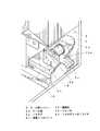
まず、図1に示す写真シール自動販売機1の外観を表した斜視図と共に、写真シール自動販売機1の構成について説明する。An embodiment of the present invention will be described below with reference to the drawings.
First, the configuration of the photo
写真シール自動販売機1はボックス状の枠で囲まれた撮像空間を備え、その一側面には筐体2が設置される。
筐体2の正面上部には、中央にデジタルカメラ17を備え、該デジタルカメラ17は撮像方向を水平よりわずかに下向けに形成して撮像方向を上下に変更可能に設ける。その周辺には、該デジタルカメラ17を左右及び上部から囲むようにして半透明部材からなる3つの拡散板162を備える。The photo
A
前記筐体2の上部は内部を空洞に形成し、前記拡散板162以外の内側面は白色に塗装して反射面163を形成する。その空洞内の中央部には、ストロボ発光する3つのストロボ照明装置161を拡散板162に背を向けて3つ備えており、1つは図2の縦断面図に示すように照明方向を少し上向きに設け、その下に図3の横断面図(平面図)に示すように照明方向を左右外開きに2つ並設する。これらのストロボ照明装置161、拡散板162及び反射面163で、被写体を正面から照明する正面ストロボ照明ボックス16bを構成する。
デジタルカメラ17の左右に設けた前記拡散板162は、図3に示すように板面を正面より内側へ向かってわずかに傾斜させ、デジタルカメラ17の上部に設けた拡散板162は、図2に示すように前面側が低くなるようにわずかに傾斜させることで、これらの各板面が被写体に対向するように形成されている。The upper part of the
The diffusing
筐体2の正面中央には、図1に示すように画像を表示するディスプレイ18を備え、該ディスプレイ18にはタッチパネル14bを重ねて設け、タッチペン14aによって落書き等をペンタッチ入力する入力装置を備える。
筐体2の正面下部には、貨幣(例えば硬貨)を投入する投入口15aを備え、その右側側面に写真シールシート5cを排出する写真シール排出口19aを備える。A
At the lower part of the front surface of the
筐体2の内部左側には、図4の部分拡大図(一部断面図)に示すように、前記写真シール排出口19aの近傍にプリンタ19を備える。
該プリンタ19には、シール紙ユニット5をセットしており、該シール紙ユニット5はロール状に巻いたシール紙5aと正規品か否かを識別させる識別データ等のデータを記憶させたIDタグ5bで構成する。As shown in a partially enlarged view (partial sectional view) of FIG. 4, a
A
前記プリンタ19の背部にはIDタグリーダ/ライタ20を備え付けており、前記IDタグ5bに記憶の前記データを読取る。
なお、前記IDタグ5bとシール紙5aは一体に形成し分離不可にしているが、別体に形成し例えばシール紙5aはプリンタ19に、IDタグ5bはIDタグリーダ/ライタ20にそれぞれセットするように構成しても良い。An ID tag reader /
Although the ID tag 5b and the
写真シール自動販売機1の枠部の天井部には、図1に示すように、撮像空間の天井面を全面的に覆うように、平面視四角形で側面視及び正面視台形の天井ストロボ照明ボックス16aを備える。該天井ストロボ照明ボックス16aは、底面に光を拡散させる拡散板162を設け、他の面の内面を白色に塗装して反射面163を形成する。前記天井ストロボ照明ボックス16aの内部には、図2の縦断面図に示すようにストロボ球が発光するストロボ照明装置161を照明方向が筐体2に向かって水平より上向きになるように備え、その反射光により被写体を上から照明する。この天井ストロボ照明ボックス16aは、前記拡散板162が水平より筐体2側に向かって少し前のめりになるように傾けて備える。As shown in FIG. 1, a ceiling strobe lighting box having a square shape in a plan view and a trapezoidal shape in a side view and a front view is provided on a ceiling portion of a frame portion of the photo
前述の照明手段の構成により、前記ストロボ照明装置161からの光は、ストロボ照明ボックス16(天井ストロボ照明ボックス16a,正面ストロボ照明ボックス16b)の内部で反射面163によって様々な方向に反射し、その反射光が拡散板162で拡散され、図2及び図3の仮想線に示すように、上から斜め後方へ向かって略均一に被写体を照射する。With the configuration of the above-mentioned lighting means, light from the
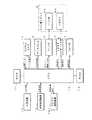
次に図5に示す写真シール自動販売機1の制御回路ブロック図と共に、写真シール自動販売機1の構造について説明する。
制御処理を実行する制御部10(図2)は筐体2の内部に設けられ、該制御部10は、CPU12、ROM11、RAM13にて形成し、CPU12はROM11に格納されているプログラムを読み込んで制御処理を実行し、RAM13に処理用データの読書きを行う。この実施の形態では、被写体である利用者をデジタルカメラ17で撮像するシャッタのタイミングと同期をとってストロボ照明装置161を発光させる制御処理も行う。Next, the structure of the photo
A control unit 10 (FIG. 2) for executing control processing is provided inside the
入力装置14は、前述したようにディスプレイ18に重ねて設けられたタッチパネル14bとタッチペン14aとにより形成され、利用者にタッチペン14aで操作された内容に該当する信号を入力信号としてCPU12に送信する。
貨幣処理装置15は、前述の投入口15aの内部に設けられ、投入された貨幣(例えば硬貨)の真偽判別、金種判別を行い、投入金額を処理信号としてCPU12に送信する。The
The
ストロボ照明装置161は、前述のストロボ照明ボックス16の各内部に収納され、それぞれCPU12からの照明制御信号に従ってストロボ発光を実行し、その光を反射面163で反射させてさらに拡散板162で拡散させ、被写体を略均一に照明する。The
デジタルカメラ17は、CPU12よりシャッタ信号を受取り、動画データや静止画データといった画像データをCPU12に送信する。
ディスプレイ18は、CPU12より画像信号を受信し、該信号に従って画像を表示する。
プリンタ19は、CPU12よりプリント画像データを受信し、シール紙5aに該プリント画像を印刷した写真シールシート5c(図4)を排出する。
IDタグリーダ/ライタ20は、シール紙ユニット5に備えたIDタグ5bに記憶されているデータを読出信号で読取り、更新信号で前記データの更新を実行する。これによって、CPU12はシール紙ユニット5が正規のものであるか否かを判定し、必要に応じて印刷回数であるカウント数を上書きする等の更新処理を実行する。The
The
The
The ID tag reader /
スピーカ21は、CPU12より音声信号を受取り、該信号に従って音声を鳴らす。(4) The speaker 21 receives the audio signal from the
以上の構造により、CPU12はストロボ照明装置161に照明制御信号を送信し、デジタルカメラ17と同期をとって照明動作を実行し、前記ストロボ照明装置161を収納したストロボ照明ボックス16で被写体を略均一に照明する。With the above structure, the
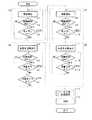
次に図6に示す処理フロー図と共に写真シール自動販売機1の動作について説明する。
利用者に貨幣(例えば硬貨)を投入口15a(図1)に投入されると、貨幣処理装置15(図5)は真偽判定、金種判定を実行し、CPU12に処理信号を送信して処理開始となる。Next, the operation of the photo
When money (for example, coins) is inserted into the insertion slot 15a (FIG. 1) by the user, the money processing device 15 (FIG. 5) executes a true / false judgment and a denomination judgment, and transmits a processing signal to the
前記処理開始を受けて、CPU12はデジタルカメラ17で撮影している映像をディスプレイ18に動画表示し、同時に撮影開始ボタンをディスプレイ18に表示して、利用者にタッチパネル14bの前記撮影開始ボタンの位置をタッチペン14aでタッチされるのを待つ(ステップn1)。In response to the start of the processing, the
利用者が前記撮影開始ボタンをタッチペン14aでタッチすると、CPU12はスピーカ21に音声信号を送信して音声によるカウントダウンを開始する。そのカウントダウンの終了と共に、デジタルカメラ17のシャッタと同期を取ってストロボ照明装置161を発光させ、反射面163で反射して拡散板162で拡散された略均一の均一光で照明された被写体を、デジタルカメラ17で静止画像撮像する。(4) When the user touches the shooting start button with the touch pen 14a, the
この間CPU12は経過時間を管理しており、制限時間(例えば60秒)が経過すれば強制的にステップn4に進む(ステップn2)。このとき、撮像画像が存在していればそれを撮像画像として強制的に採用し、まだ1枚も撮像されていない場合には強制的に撮像を実行してその撮像画像を採用してもよい。
なお、前記制限時間は、撮像画像が決定されるまでの間、CPU12によってディスプレイ18にカウントダウンして表示させる。During this time, the
Note that the
撮像終了時に制限時間が経過していなければ、CPU12はディスプレイ18に前記撮像画像を静止画表示し、同時にキープボタンと撮り直しボタンを表示する。利用者に撮り直しボタンをタッチされた場合はステップn1に戻る。キープボタンをタッチされた場合は、CPU12はステップn1からステップn3までの一連の工程Aで経過した時間(例えば40秒)を前記制限時間から減算し、算出された残時間(この場合は20秒)をRAM13に記憶させて次のステップに進む(ステップn3)。If the time limit has not elapsed at the end of imaging, the
CPU12はディスプレイ18にRGB信号を送信して前記撮像画像を表示させ、ROM12に記憶させている工程Aでの残時間(この場合は20秒)をこれから実行する工程Bの制限時間(例えば60秒)に加算して、制限時間を増加(この場合は80秒)させる(ステップn4)。このとき同時にディスプレイ18には次撮影ボタンと印刷ボタンを表示させ、利用者はタッチペン14aにて落書き画像に落書きを開始する。The
CPU12は工程Bの経過時間を管理し、前記加算した制限時間内(この場合は80秒)であれば次のステップに進み、制限時間が経過すればステップn7に強制的に進む(ステップn5)。
CPU12は、利用者が落書き中であれば、ステップn5に戻り、落書きが終了すれば次のステップに進む(ステップn6)。The
The
利用者に印刷ボタンをタッチペン14aでタッチされると、ステップn14へ一気に進む。次撮影ボタンをタッチされた場合には、CPU12はステップn4からステップn7までの工程Bでの経過時間(例えば50秒)を制限時間(この場合は80秒)から減算し、算出された残時間(この場合は30秒)をRAM13に記憶させて次のステップに進む(ステップn7)。
なお、この次撮影ボタンをタッチされるまでの間、CPU12は工程Bの制限時間(この場合は80秒)をディスプレイ18に表示させている制限時間表示部にカウントダウンして表示させる。When the user touches the print button with the touch pen 14a, the process goes to step n14. When the next shooting button is touched, the
Until the next photographing button is touched, the
次の工程Cはステップn8からステップn10の3つのステップからなり、前記工程Aと同じ動作で撮像処理を行う。ただしこのときは、工程Cの最初のステップn8でCPU12は前記工程Bでの残時間(この場合は30秒)を制限時間(60秒)に加算して制限時間を増加(この場合は90秒)して処理を行う(ステップn8からn10)。The next step C is composed of three steps from step n8 to step n10, and the imaging process is performed by the same operation as the step A. However, in this case, in the first step n8 of the process C, the
次の工程Dはステップn11からステップn12の3つのステップからなり、前記工程Bのステップn4からステップn6の3つのステップと同じ動作を行う。前記工程Cで例えば40秒使用したとすると、残りの50秒が工程Dに与えられている制限時間、例えば60秒に加算され、利用者は110秒の間落書きを行うことができる(ステップn11からn13)。なお、この工程Dでの落書きにおいては、CPU12はサムネイル画像として工程Bでの落書き画像と工程Dでの落書き画像を縮小表示させ、利用者にタッチペン14aでタッチされることで落書き画像を選択された落書き画像に入れ替える。これにより、利用者は工程Dで時間が余れば、工程Aでの落書きの続きを行うことができる。The next step D is composed of three steps n11 to n12, and performs the same operation as the three steps n4 to n6 of the step B. Assuming that, for example, 40 seconds have been used in the process C, the remaining 50 seconds are added to the time limit given in the process D, for example, 60 seconds, and the user can perform graffiti for 110 seconds (step n11). To n13). Note that, in the graffiti in the process D, the
次のステップでは、CPU12はディスプレイ18にRGB信号を送信して後述するシール分割・配置選択処理を実行する(ステップn14)。In the next step, the
前記シール分割・配置選択処理が終了すると、CPU12は選択された分割数及び配置に従って落書き画像を配置した写真シールシート5cをプリンタ19に印刷させ、写真シール排出口19aから排出させる(ステップn15)。When the sticker division / arrangement selection process is completed, the
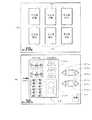
ここで前記シール分割・配置選択処理について、図7に示す処理フロー図と共に説明すると、CPU12は、まず図8の画面イメージ説明図の(A)に示す分割数選択画面をディスプレイ18に表示させる(ステップs1)。該分割数選択画面には分割数選択ボタン30を6つ表示し、それぞれに2人用均等、2人用混合、3人用均等、3人用混合、多人数均等、多人数混合を選択する機能を割り当てる。利用者は、例えば10秒に設定された制限時間内で前記分割数選択ボタン30の1つ(例えば2人用混合)をタッチペン14aでタッチする(ステップs2)。前記制限時間内に前記分割数選択ボタン30の1つがタッチされなければ、例えば2人用均等を選択されたと強制的に決定して次のステップに進む(ステップs3)。Here, the seal division / arrangement selection processing will be described with reference to a processing flowchart shown in FIG. 7. First, the
なお、前記分割数選択ボタン30のうち、混合と表示された3つのボタンは印刷サイズの異なる落書き画像を混合させて印刷する場合に選択し、均等と表示された3つのボタンは印刷サイズを均等に配置した落書き画像を印刷する場合に選択する。Of the division
CPU12は前述のタッチによる入力信号を受けてその選択をROM11に記憶させ(ステップs4)、ディスプレイ18に図8の(B)に示す配置選択画面を表示させる(ステップs5)。該配置選択画面には印刷画像表示部35を表示し、前述の分割数の選択(この場合は2人用であるので2分割)に対応して、上部印刷画像表示部35aと下部印刷画像表示部35bに中央で上下に横点線にて分割する。
該印刷画像表示部35の右側には、前記横点線の上下に分けて配置選択部を表示する。該配置選択部は、前記横点線の上側には上部印刷画像表示部35a内の落書き画像の配置を選択するための進むボタン32a、戻るボタン31a、最初の表示ボタン33aを表示し、下側には下部印刷画像表示部35b内の落書き画像の配置を選択するための進むボタン32b、戻るボタン31b、最初の表示ボタン33bを表示する。なお、図8の前記印刷画像表示部35を左右に分割している縦点線は、左側に1回目の撮像による落書き画像、右側に2回目の撮像による落書き画像を分けて表示していることを示す補助線である。The
On the right side of the print
利用者甲は、選択用ボタンである進むボタン32a、戻るボタン31a、最初の表示ボタン33aをタッチして自分の欲しい枚数、大きさに配置された上部印刷画像表示部35a内の落書き画像の配置を選択し、利用者乙は同様に進むボタン32b、戻るボタン31b、最初の表示ボタン33bをタッチして自分の欲しい枚数、大きさに配置された下部印刷画像表示部35b内の落書き画像の配置を選択する(ステップs6)。The user A touches the forward button 32a, the return button 31a, and the first display button 33a, which are selection buttons, and places the graffiti image in the upper print image display section 35a arranged in the number and size desired by the user. And the user B similarly touches the forward button 32b, the back button 31b, and the first display button 33b, and places the graffiti image in the lower print image display section 35b arranged in the number and size desired by the user. Is selected (step s6).
利用者が例えば30秒に設定された制限時間内で前記選択を終了して印刷ボタン34をタッチすると次のステップである図6に示したステップn15に進み(ステップs7)、前記印刷ボタン34をタッチされなくても前記制限時間が経過すれば強制的に図6に示したステップn15に進む(ステップs8)。When the user finishes the selection and touches the
以上の動作により、利用者はストロボ照明ボックス16によって略均一に細部まで照明されて撮像することができ、特に図9の撮像画像に対する照明効果の説明図の(a)に示すように頭髪の質感を明瞭に撮像することができるため、図中の(b)に示す従来の撮像での頭髪の質感と比較して利用者に与える満足度の向上は顕著であり、その満足度の高い撮像画像に対して落書き編集をした編集画像を印刷した写真シールシート5cを得ることができる。By the above operation, the user can illuminate the image with the
第2の実施例として、上述の写真シール自動販売機1は、図10の斜視図に示すように形成することもできる。すなわちボックス状の枠部上部を拡散板162の傾きに合わせて一部傾斜させて形成し、拡散板162を除く天井部を適宜の板材で覆うことができる。As a second embodiment, the above-mentioned photo
この実施例によれば、撮像空間の天井部と天井ストロボ照明ボックス16aの底面(つまり拡散板162)が密着しているため、該天井ストロボ照明ボックス16aの照明光が撮像空間の外に洩れず、効率よく被写体を照明することができる。According to this embodiment, since the ceiling of the imaging space and the bottom surface of the ceiling
この実施例においても、写真シール自動販売機1の構造及び動作は前述の実施例と同じであるので、同一機能を有するものには同一符号を付して詳細な説明を省略する。Also in this embodiment, since the structure and operation of the photo
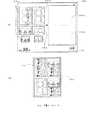
なお、上述の2つの実施例では撮像空間の天井に1つの大きな天井ストロボ照明ボックス16aを設けたが、第3の実施例として図11の左側面から見た縦断面図に示すように、小型に形成した小型ストロボ照明ボックス16cを複数設けても良い。これにより、撮像空間の天井面を天井ストロボ照明ボックス16aで覆って照明する場合と同様に撮像空間全体を上から照明することができる。また、図11に示す被写体Mに斜線で表すように、複数人の被写体Mが存在する場合であっても、それぞれを十分照明することができ、正面からの照明では光が届かず陰になるような部分も照明できる。In the above two embodiments, one large ceiling
また第4の実施例として、前記小型ストロボ照明ボックス16cは、図12の横断面図に示すように、撮像空間の後方側の設置数を増加させても良い。これにより、正面ストロボ照明ボックス16bの照明光があまり届かない後方の被写体Mを十分照明することができる。
また、図12と共に説明したように小型ストロボ照明ボックス16cの数を変化させる代わりに、小型ストロボ照明ボックス16cは一律に配置して後方の小型ストロボ照明ボックス16cの光量を強く設定しても良い。As a fourth embodiment, as shown in the cross-sectional view of FIG. 12, the number of the small
Further, instead of changing the number of the small
また第5の実施例として、図13の左側面から見た縦断面図に示すように、天井ストロボ照明ボックス16aを水平に設置し、該天井ストロボ照明ボックス16aの拡散板162を側面視のこぎり型に形成しても良い。これにより照明光は真下よりも少し後方へ向かい、前述の実施例で天井ストロボ照明ボックス16aを前方へ傾けたのと同様の効果を得ることができ、前後に並んだ被写体の後方の被写体をも照明することができる。加えて、天井ストロボ照明ボックス16aを傾ける必要がないため、該天井ストロボ照明ボックス16aの組立時の構造が簡略化される。As a fifth embodiment, as shown in a vertical sectional view seen from the left side of FIG. 13, a ceiling
また第6の実施例として、前記ストロボ照明ボックス16は、側面や背面、床面等に設けても良い。例えば側面に設けた場合であれば、図14の横断面図に示すように、被写体Mを側面斜め前から照明することができ、正面からの照明では影になりやすい被写体Mの側部等を十分照明することができる。As a sixth embodiment, the
また第7の実施例として、図15の左側面から見た縦断面図に示すように、前記小型ストロボ照明ボックス16cを可動するように形成しても良い。この場合、前記小型ストロボ照明ボックス16cは、内部に備えた雌ネジ部分に挿入した雄ネジ型のシャフトSを正逆転するパルスモータPで回転させることで、断面がL字型のガイドフレームSに沿って前後に可動する。
これにより、被写体Mの位置に合わせて、照明の必要な部分を十分照明することができる。As a seventh embodiment, as shown in a vertical cross-sectional view as viewed from the left side of FIG. 15, the small
Thereby, it is possible to sufficiently illuminate a portion that requires illumination in accordance with the position of the subject M.
また、前記小型ストロボ照明ボックス16cは、拡散板162及び反射面163を備えず、ストロボ照明装置161で直接被写体Mを照明するように形成しても良い。通常ストロボ照明はコントラストが強調されやすいため、拡散板162及び反射面163を備えて被写体Mをソフトに照明するように形成したが、複数のストロボ照明装置161で照明すれば、被写体Mをソフトに照明することができる。The small-sized
また、利用者が主に顔を撮影するアップ撮影と、主に全身を撮影する全身撮影のどちらを選ぶかによって、アップ撮影の時は光量を少なく、全身撮影のときは光量を多くして、撮影の照明光度のバランスを取るように設定しても良い。このとき、撮影パターン(例えばアップ撮影か前進撮影のどちらか等)によって照明光度のバランス等を変化させてもよいし、利用者が自分で照明光度のバランス等を調節できるように構成しても良い。In addition, depending on whether the user selects up-shooting mainly for taking a picture of the face or full-body shooting mainly for taking the whole body, the amount of light is reduced during up-shooting and the amount of light is increased during whole-body shooting. The setting may be made so as to balance the luminous intensity of the shooting. At this time, the balance of the illumination luminosity may be changed depending on the photographing pattern (for example, one of the up photography and the forward photography), or the user may be able to adjust the balance of the illumination luminosity by himself. good.
また、前面と天井のストロボ照明装置161は、同時に発光させるだけでなくどちらか一方のみを発光させることもできるように、利用者が入力手段14で選択できるように形成してもよい。これにより、例えば被写体を1側面から照明して照明側は明るくその反対側は影になるような照明効果を得ることができ、撮像に対する娯楽性を高めることができる。Also, the
また、反射面163は光が反射すればよいので、白色の塗装に変えて銀色の塗装又は銀メッキ等にしてもよいし、素材を紙等の拡散効果の高いものにしてもよい。Since the
また、照明の光を略均一にする方法として、前述の実施例で説明した反射面163による光の反射、又は拡散板162による光の拡散のどちらか一方のみを使用しても良い。この場合は、被写体を略均一に照明する機能をある程度有した上でコストダウンを図ることができる。As a method for making the light of illumination substantially uniform, only one of the reflection of light by the
また、ストロボ照明装置161はデジタルカメラ17からシンクロ信号を受信するように構成し、デジタルカメラ17の撮像と同期をとって前記シンクロ信号に従って発光するように構成しても良い。Also, the
また、第1の実施例で図7と共に説明したシール分割・配置選択処理について詳述すると、図7に示したサブルーチンにおいて、ステップs2で前記分割数選択ボタン30にて例えば3人用均等が選択された場合は、ステップs5で図16の(C)に示す配置選択画面を表示させると良い。この場合は3人用であるので、印刷画像表示部35は上部印刷画像表示部35c、中部印刷画像表示部35d、下部印刷画像表示部35eの3つに均等に分割され、上部には進むボタン32c、戻るボタン31c、最初の表示ボタン33c、中部には進むボタン32d、戻るボタン31d、最初の表示ボタン33d、下部には進むボタン32e、戻るボタン31e、最初の表示ボタン33eがそれぞれ対応している。これにより、ハサミ等で3つに容易に分割できる写真シールシート5cを得ることができる。In the subroutine shown in FIG. 7, in the subroutine shown in FIG. 7, in the subroutine shown in FIG. In this case, the arrangement selection screen shown in FIG. 16C may be displayed in step s5. In this case, for three people, the print
また、そのサブルーチンにおいて、ステップs2で前記分割数選択ボタン30にて例えば多人数混合を選択した場合には、ステップs5で図16の(D)に示す配置選択画面を表示させると良い。この場合は横点線による分割はなく縦点線による分割のみであり、印刷画像表示部35の右側に表示した進むボタン32f、戻るボタン31f、最初の表示ボタン33fで全体の配置を選択する。利用者は、1回目の撮像による落書き画像と2回目の撮像により落書き画像を縦点線で縦に分割した後、それぞれを分配することができる。{Circle around (4)} In the subroutine, when, for example, multi-person mixing is selected by the division
これにより、利用者は撮像画像に落書き編集を行った落書き画像(落書き編集してない場合は撮像画像)を容易に分割できるように配置した写真シールシート5cを得ることができる。(4) Thus, the user can obtain the
なお、図8の(B)、図16の(C)及び(D)に示した縦点線を省き、例えば図8の(B)であれば、上部印刷画像表示部35a及び下部印刷画像表示部35bをそれぞれ一体にして、上部印刷画像表示部35aには1回目の落書き画像のみを配置し、下部印刷画像表示部35bには1回目及び2回目の落書き画像を配置するような選択も可能に形成してもよい。これにより、利用者の選択できる自由度がさらに向上する。Note that the vertical dotted lines shown in FIGS. 8B, 16C and 16D are omitted, and for example, in the case of FIG. 8B, the upper print image display unit 35a and the lower print image display unit It is also possible to select the arrangement in which only the first graffiti image is arranged in the upper print image display section 35a and the first and second graffiti images are arranged in the lower print image display section 35b. It may be formed. As a result, the degree of freedom that the user can select is further improved.
また、例えば図8の(B)で進むボタン32b、戻るボタン31b、最初の表示ボタン33bを表示せず、進むボタン32a、戻るボタン31a、最初の表示ボタン33aを操作して横点線で分割して落書き画像が配置された印刷用画像を印刷画像表示部35に表示するように形成してもよい。これにより、単純なインターフェースで利用者はハサミ等で容易に分割可能な写真シールシート5cを得ることができる。
また、前記印刷画像表示部35は横点線で縦方向に分割したが、これにかぎらず横方向等に分割してもよい。In addition, for example, the forward button 32b, the return button 31b, and the first display button 33b are not displayed in FIG. 8B, and the forward button 32a, the return button 31a, and the first display button 33a are operated to divide by a horizontal dotted line. The print image on which the graffiti image is arranged may be displayed on the print
The print
また、図8の(A)と共に説明した分割数の選択、図8の(B)及び図16の(C),(D)と共に説明した印刷画像表示部35への落書き画像の配置は、以下の各実施例のように構成することができる。The selection of the number of divisions described with reference to FIG. 8A and the arrangement of the graffiti image on the print
第8の実施例として、第1の実施例で図8の(A)と共に説明した分割数選択画面を、図17に示す画面イメージ図のようにすることができる。
すなわち、図中の(E)に示すように、分割数選択ボタン30として実際に分割線を表示したシール紙5aのイメージを表示して、利用者に分割位置を選択させることができる。As an eighth embodiment, the division number selection screen described with reference to FIG. 8A in the first embodiment can be configured as a screen image diagram shown in FIG.
That is, as shown in (E) in the figure, the user can select the division position by displaying the image of the
前記分割位置を選択後に次へボタン37を利用者にタッチされると、次の配置選択画面(図8の(B))を表示する。なお、次へボタン37を設けず、前記分割数選択ボタン30をタッチすれば配置選択画面を表示するように構成してもよい。
本実施例によれば、分割位置が均等でなくても目でみて分割位置が確認できるためメンタルモデル的にわかりやすく、分割位置の選択の幅を広げることができる。When the user touches the
According to this embodiment, even if the division positions are not uniform, the division positions can be visually confirmed, so that it is easy to understand as a mental model, and the range of selection of the division positions can be widened.
第9の実施例として、第1の実施例で図8の(B)及び図16の(C),(D)と共に説明した印刷画像表示部35への落書き画像の配置の決定を、図18の画面説明図に示すように、ドラッグ&ドロップで行うことができる。すなわち、図中の(F)の画面イメージ図に示すように、利用者にタッチペン14aで落書き画像36a,36bのいずれかをタッチして選択させ、次に上部印刷画像表示部35a又は下部印刷画像表示部35bにタッチさせることで、サイズの異なる落書き画像36(36a,36b)を、上部印刷画像表示部35a及び下部印刷画像表示部35bに自由に配置することができる。As a ninth embodiment, the determination of the arrangement of the graffiti image on the print
このように配置して印刷した例として、図中の(G)に示すような写真シールシート5cを得ることができる。該写真シールシート5cには、ハサミ等で分割する位置が識別できるように、落書き画像36と共に点線の分割線5dを印刷する。
本実施例によれば、利用者が任意の位置に任意の落書き画像36を配置できるため、利用者が得られる配置のバリエーションが増加する。As an example of such arrangement and printing, a
According to the present embodiment, since the user can arrange an
第10の実施例として、落書き画像の配置の決定を、図19の画面説明図に示すように落書き画像を配置するパターンを先に選択させて、その後に配置する落書き画像を選択させて決定することができる。As a tenth embodiment, the arrangement of graffiti images is determined by first selecting a pattern for arranging graffiti images and then selecting a graffiti image to be arranged as shown in the screen explanatory diagram of FIG. be able to.
すなわち、図中の(H)の画面イメージ図に示すように、利用者に進むボタン32(32a,32b)、戻るボタン31(31a,31b)、最初の表示ボタン33(33a,33b)で落書き画像を配置するパターンを選択させて該パターンを印刷画像表示部35に表示し、利用者に落書き画像36をタッチして選択させ、前記印刷画像表示部35にタッチさせることで、タッチされた部分(例えばAがタッチされれば6つのA全て)に前記落書き画像36を配置する。That is, as shown in the screen image diagram of (H) in the figure, a graffiti image is displayed by a user proceeding button 32 (32a, 32b), a return button 31 (31a, 31b), and a first display button 33 (33a, 33b). Is displayed on the print
図中の(I)は、前記印刷画像表示部35に表示するパターンの例を示しており、例えば上部印刷画像表示部35aのAには落書き画像36a、Bには落書き画像36cを配置し、下部印刷画像表示部35bのAには落書き画像36b、Bには落書き画像36cを配置した場合であれば図中の(J)に示すような写真シールシート5cが得られる。(I) in the figure shows an example of a pattern displayed on the print
以上の第8,第9及び第10の実施例においても、他の構成・構造・動作は前述の第1の実施例と同様であるので、同一部分には同一符号を付して、詳細な説明を省略する。In the above-described eighth, ninth, and tenth embodiments, the other configurations, structures, and operations are the same as those in the first embodiment. Description is omitted.
なお、分割線5dは、ハサミマークや矢印等の目印を印刷しても良いし、他の部分より余白部分を多くして分割位置が識別できるようにしても良いし、写真シールシート5cの台紙としてミシン目を入れたシール紙5aを準備しておいても良い。Note that the dividing line 5d may be printed with a mark such as a scissor mark or an arrow, may have a margin portion larger than other portions so that the dividing position can be identified, and the mounting sheet of the
また、図7のステップs1で行った分割数の選択は、図6のステップn1とステップn2の間で行うように設定しても良い。またこのとき、分割数を選択した後にOKか否かを選択させるように設定しても良い。
また、前述の入力装置14は、タッチパネル14bを人が指でタッチすることで入力を許容するタッチパネルで形成してもよい。The selection of the number of divisions performed in step s1 in FIG. 7 may be set to be performed between step n1 and step n2 in FIG. At this time, it may be set so as to allow the user to select OK or not after selecting the number of divisions.
The
また第11の実施例として、図6と共に説明した写真シール自動販売機1の動作を示す処理フローの他の形態について、図20に示す処理フロー図と共に説明する。
この実施例では、撮影工程である工程Eを2回繰り返し、編集工程である工程F,Gで2枚の撮影画像に落書きを行う場合について説明する。As an eleventh embodiment, another embodiment of the processing flow showing the operation of the photo
In this embodiment, a case will be described in which step E which is a photographing step is repeated twice, and graffiti is performed on two photographed images in steps F and G which are edit steps.
利用者に貨幣(例えば硬貨)を投入口15a(図1)に投入されると、貨幣処理装置15(図5)は真偽判定、金種判定を実行し、CPU12に処理信号を送信して処理開始となる。When money (for example, coins) is inserted into the insertion slot 15a (FIG. 1) by the user, the money processing device 15 (FIG. 5) executes a true / false judgment and a denomination judgment, and transmits a processing signal to the
前記処理開始を受けて、CPU12はデジタルカメラ17で撮影している映像をディスプレイ18に動画表示し、同時に撮影開始ボタンをディスプレイ18に表示して、利用者にタッチパネル14bの前記撮影開始ボタンの位置をタッチペン14aでタッチされるのを待つ(ステップu1)。In response to the start of the processing, the
利用者が前記撮影開始ボタンをタッチペン14aでタッチすると、CPU12はスピーカ20に音声信号を送信して音声によるカウントダウンを開始する。そのカウントダウンの終了と共にストロボ照明装置16を発光させ、同時にデジタルカメラ17で静止画像を撮影する。この間CPU12は経過時間を管理しており、制限時間(例えば60秒)が経過すれば強制的にステップu5に進む(ステップu2)。このとき、撮影画像が存在していればそれを撮影画像として強制的に採用し、まだ1枚も撮影されていない場合には強制的に撮影を実行してその撮影画像を採用する。
なお、前記制限時間は、撮影画像が決定されるまでの間、CPU12によってディスプレイ18にカウントダウンして表示させ、制限時間が残り少なくなると(例えば残り10秒)、CPU12がスピーカ20に音声信号を送信して利用者に警告する。When the user touches the shooting start button with the touch pen 14a, the
The time limit is counted down and displayed on the
撮影終了時に制限時間が経過していなければ、CPU12はディスプレイ18に前記撮影画像を静止画表示し、同時にキープボタンと撮り直しボタンを表示する。利用者に撮り直しボタンをタッチされた場合はステップu1に戻る。キープボタンをタッチされた場合は、CPU12はステップu1からステップu3までの一連の工程Eで経過した時間(例えば50秒)を前記制限時間から減算し、算出された残時間(この場合は10秒)をRAM13に記憶させて次のステップに進む(ステップu3)。If the time limit has not elapsed at the end of shooting, the
ここで、キープされた撮影画像が1枚目であれば(つまり最後でなければ)、ステップu1に戻り、2枚目であれば(つまり最後であれば)、次のステップに進む(ステップu4)。Here, if the kept captured image is the first image (that is, if it is not the last), the process returns to step u1, and if it is the second image (that is, if it is the last), the process proceeds to the next step (step u4). ).
このとき、CPU12はディスプレイ18にRGB信号を送信して前記撮影画像を表示させ、ROM12に記憶させている工程Eでの残時間(この場合は10秒)をこれから実行する工程Fの制限時間(例えば60秒)に加算して、制限時間を増加(この場合は70秒)させる。これと同時にディスプレイ18には印刷ボタンと、第1の実施例の次撮影ボタンに変えて次落書きボタン(図示省略)を表示させる(ステップu5)。
利用者はタッチペン14aにて図21の画面イメージ図に示すペン18aと消しゴムペン18bで落書き画像18cに落書きを行う。At this time, the
The user draws on the doodle image 18c with the
CPU12は工程Fの経過時間を管理し、前記加算した制限時間内(この場合は70秒)であれば次のステップに進み、制限時間が経過すればステップu9に強制的に進む(ステップu6)。
CPU12は、利用者が落書き中であれば、ステップu6に処理を戻し、落書きが終了すれば次のステップに処理を進める(ステップu7)。The
If the user is graffitiing, the
利用者に印刷ボタンをタッチペン14aでタッチされると、SPU12はステップu13へ一気に処理を進め、次落書きボタンをタッチされた場合には、ステップu5からステップu8までの工程Fでの経過時間(例えば50秒)を制限時間(この場合は70秒)から減算し、算出された残時間(この場合は20秒)をRAM13に記憶させて次のステップに処理を進める(ステップu8)。
なお、この次落書きボタンをタッチされるまでの間、CPU12は工程Fの制限時間(この場合は70秒)をディスプレイ18に表示させている制限時間表示部18g(図21)にカウントダウンして表示させ、制限時間が残り少なくなると(例えば残り10秒)、CPU12がスピーカ20に音声信号を送信して利用者に警告する。When the user touches the print button with the touch pen 14a, the
Until the next graffiti button is touched, the
次の工程Gはステップu9からステップu12の4つのステップからなり、前記工程Fのステップu5からステップu8の4つのステップと同様の動作を行う。The next step G is composed of four steps from step u9 to step u12, and performs the same operation as the four steps from step u5 to step u8 of the step F.
現在工程E,Fを経て20秒の余り時間があるため、工程Gの制限時間は本来の60秒に20秒を加算され、利用者は80秒の間落書きを行うことができる(ステップu9からs12)。なお、この工程Gでは、工程Fでディスプレイ18に表示されていた次落書きボタンを前落書きボタンに変更する(図示省略)。Since there is a remaining time of 20 seconds after steps E and F at present, the time limit of step G is obtained by adding 20 seconds to the original 60 seconds, and the user can perform graffiti for 80 seconds (from step u9). s12). In the process G, the next graffiti button displayed on the
このとき、制限時間内(例えば55秒)にステップu12で利用者が前落書きボタンをタッチすると、CPU12は処理をステップu5に戻し、余り時間の間(つまり25秒)1枚目の撮影画像に対する落書きを許容する。At this time, if the user touches the previous graffiti button in step u12 within the time limit (for example, 55 seconds), the
次のステップu13では、CPU12はディスプレイ18にRGB信号を送信してシール分割数及び配置(例えば16分割均等配置など)を選択させる画面を表示させ、利用者にタッチペン14aでタッチして選択させる(ステップu13)。In the next step u13, the
前記選択がされると、CPU12は選択された分割数及び配置に従って落書き画像を配置した写真シールシート5cをプリンタ19に印刷させ、写真シール排出口19aから排出させる(ステップu14)。When the selection is made, the
以上の動作により、撮影した2枚の撮影画像に対してそれぞれ制限時間を設定した編集工程で落書きを行うため、意図しない落書き洩れを防止することができる。
図20と共に説明したこの実施例においても、他の構成・構造は第1の実施例と同様であるので、詳細な説明を省略する。By the above operation, graffiti is performed on the two photographed images in the editing process in which the time limit is set, so that unintended graffiti leakage can be prevented.
In this embodiment described with reference to FIG. 20, the other configurations and structures are the same as those of the first embodiment, and thus detailed description will be omitted.
なお、以上の実施例において前記ステップu4での最後か否かの判断は、例えば印刷終了ボタンを表示して利用者にタッチさせることで、2枚に限らず複数枚キープ可能に設定しても良い。In the above-described embodiment, the determination as to whether or not it is the last in step u4 may be made, for example, by displaying a print end button and touching the user. good.
また、前記ステップu2で制限時間が経過したときに、ステップu4に進むように設定し、制限時間を設定した工程Eを複数回繰り返して実行することを可能に設定しても良い。
また、工程Eでの余り時間を次の工程Fに追加しない設定にしても良い。Further, when the time limit has elapsed in step u2, the process may be set so as to proceed to step u4, and the process E in which the time limit is set may be set to be executed a plurality of times.
Further, a setting may be made such that the surplus time in the process E is not added to the next process F.
この発明の構成と、上述の実施形態との対応において、
この発明の写真シール自動販売装置は、実施形態の写真シール自動販売機1に対応し、
以下同様に、
識別体は、IDタグ5bに対応し、
制御手段は、CPU12、ROM11及びRAM13に対応し、
編集手段は、入力装置14に対応し、
発光体は、ストロボ照明装置161に対応し、
照明手段である天井ストロボ照明ボックスは、小型ストロボ照明ボックス16cに対応し、
撮像手段は、デジタルカメラ17に対応し、
出力手段は、プリンタ19に対応し、
識別手段は、IDタグリーダ/ライタ20に対応するも、
この発明は、上述の実施形態の構成のみに限定されるものではない。In correspondence between the configuration of the present invention and the above embodiment,
The photo sticker vending device of the present invention corresponds to the photo
Similarly,
The identifier corresponds to the ID tag 5b,
The control means corresponds to the
The editing means corresponds to the
The illuminant corresponds to the
The ceiling strobe lighting box as the lighting means corresponds to the small
The imaging means corresponds to the
The output means corresponds to the
The identification means corresponds to the ID tag reader /
The present invention is not limited only to the configuration of the above embodiment.
1…写真シール自動販売機
5…シール紙ユニット
5a…シール紙
5b…IDタグ
5c…写真シールシート5c
10…制御部
16…ストロボ照明ボックス
16a…天井ストロボ照明ボックス
16b…正面ストロボ照明ボックス
16c…小型ストロボ照明ボックス
17…デジタルカメラ
19…プリンタ
20…IDタグリーダ/ライタ
161…ストロボ照明装置
162…拡散板
163…反射面
1. Photo
DESCRIPTION OF
Claims (8)
Translated fromJapanese編集対象の画像に対して編集手段で編集して編集画像を作成する編集処理を許容し、
所定の画像を出力画像として出力手段で出力する写真シール自動販売方法であって、
前記照明手段を上から斜め後方に向かって被写体を照射するよう水平より前面側に向かって少し前のめりになるように傾けて前記撮像空間の天井部に配置した複数の天井ストロボ照明ボックスで構成し、
該複数の天井ストロボ照明ボックスによって撮像と同期して被写体を照明する
写真シール自動販売方法。An imaging process of illuminating one or more subjects with illumination means and imaging with an imaging means provided in front of a box-shaped imaging space to create a captured image;
Allow editing processing to edit the image to be edited by editing means to create an edited image,
A photo sticker vending method of outputting a predetermined image as an output image by an output unit,
The lighting unit is configured with a plurality of ceiling strobe lighting boxes arranged on the ceiling of the imaging space by being tilted so as to slightly turn forward from the horizontal side toward the front side so as to irradiate the subject diagonally rearward from above,
A method of automatically selling a photo sticker in which a subject is illuminated in synchronization with imaging by the plurality of ceiling strobe lighting boxes.
請求項1に記載の写真シール自動販売方法。2. The automatic photo sticker vending method according to claim 1, wherein the number of ceiling strobe lighting boxes installed behind the plurality of ceiling strobe lighting boxes is set to be greater than that on the front side to illuminate a subject in synchronization with imaging.
請求項1又は2に記載の写真シール自動販売方法。3. The method according to claim 1, wherein a light amount of a ceiling strobe lighting box on a rear side of the plurality of ceiling strobe lighting boxes is set stronger than that on a front side, and a subject is illuminated in synchronization with imaging. .
請求項1から3のいずれか1つに記載の写真シール自動販売方法。4. The method according to claim 1, wherein the plurality of ceiling strobe lighting boxes are moved to illuminate a subject in synchronization with imaging. 5.
編集対象の画像に対して編集手段で編集して編集画像を作成する編集処理を許容し、
所定の画像を出力画像として出力手段で出力する写真シール自動販売装置であって、
前記照明手段を上から斜め後方に向かって被写体を照射するよう水平より前面側に向かって少し前のめりになるように傾けて前記撮像空間の天井部に配置した複数の天井ストロボ照明ボックスで構成し、
該複数の天井ストロボ照明ボックスによって撮像と同期して被写体を照明するよう設定した
写真シール自動販売装置。An imaging process of illuminating one or more subjects with illumination means and imaging with an imaging means provided in front of a box-shaped imaging space to create a captured image;
Allow editing processing to edit the image to be edited by editing means to create an edited image,
A photo sticker vending device that outputs a predetermined image as an output image by an output unit,
The illumination means is configured by a plurality of ceiling strobe lighting boxes arranged on the ceiling of the imaging space by being tilted so as to slightly turn forward from the horizontal side toward the front side so as to irradiate the subject diagonally rearward from above,
An automatic vending machine for photo stickers set to illuminate a subject in synchronization with imaging by the plurality of ceiling strobe lighting boxes.
請求項5に記載の写真シール自動販売装置。The photo sticker vending device according to claim 5, wherein the number of installations on the rear side of the plurality of ceiling strobe lighting boxes is arranged to be greater than that on the front side.
請求項5又は6に記載の写真シール自動販売装置。7. The vending machine according to claim 5, wherein a light amount of a ceiling strobe lighting box on a rear side of the plurality of ceiling strobe lighting boxes is set to be higher than that on a front side. 8.
請求項5から7のいずれか1つに記載の写真シール自動販売装置。
8. The vending machine according to claim 5, wherein the positions of the plurality of ceiling strobe lighting boxes are movably provided.
Priority Applications (1)
| Application Number | Priority Date | Filing Date | Title |
|---|---|---|---|
| JP2003347017AJP2004102300A (en) | 2001-06-08 | 2003-10-06 | Method and machine for automatically vending photograph sticker |
Applications Claiming Priority (3)
| Application Number | Priority Date | Filing Date | Title |
|---|---|---|---|
| JP2001173441 | 2001-06-08 | ||
| JP2001313415 | 2001-10-11 | ||
| JP2003347017AJP2004102300A (en) | 2001-06-08 | 2003-10-06 | Method and machine for automatically vending photograph sticker |
Related Parent Applications (1)
| Application Number | Title | Priority Date | Filing Date |
|---|---|---|---|
| JP2002030443ADivisionJP3502946B2 (en) | 2001-06-08 | 2002-02-07 | Photo-seal automatic vending method and device, seal paper unit and photo-seal sheet |
Publications (1)
| Publication Number | Publication Date |
|---|---|
| JP2004102300Atrue JP2004102300A (en) | 2004-04-02 |
Family
ID=32303153
Family Applications (1)
| Application Number | Title | Priority Date | Filing Date |
|---|---|---|---|
| JP2003347017APendingJP2004102300A (en) | 2001-06-08 | 2003-10-06 | Method and machine for automatically vending photograph sticker |
Country Status (1)
| Country | Link |
|---|---|
| JP (1) | JP2004102300A (en) |
Cited By (2)
| Publication number | Priority date | Publication date | Assignee | Title |
|---|---|---|---|---|
| JP2006323286A (en)* | 2005-05-20 | 2006-11-30 | Make Softwear:Kk | Automatic picture preparing apparatus, control method and program thereof |
| JP2019101076A (en)* | 2017-11-29 | 2019-06-24 | フリュー株式会社 | Photographic sticker forming apparatus |
- 2003
- 2003-10-06JPJP2003347017Apatent/JP2004102300A/enactivePending
Cited By (2)
| Publication number | Priority date | Publication date | Assignee | Title |
|---|---|---|---|---|
| JP2006323286A (en)* | 2005-05-20 | 2006-11-30 | Make Softwear:Kk | Automatic picture preparing apparatus, control method and program thereof |
| JP2019101076A (en)* | 2017-11-29 | 2019-06-24 | フリュー株式会社 | Photographic sticker forming apparatus |
Similar Documents
| Publication | Publication Date | Title |
|---|---|---|
| KR100527618B1 (en) | Automatic photograph seal vending method, apparatus therefor, photograph seal paper unit, and photograph seal sheet | |
| JP2005079662A (en) | Image editing method in photograph vending machine, photograph vending machine, and image editing program | |
| JP5423124B2 (en) | Photo editing device | |
| JP2006072045A (en) | Automatic photographing device | |
| JP2003241296A (en) | Automatic vending method for photograph seal, equipment for the same, seal paper unit, and photographic seal sheet | |
| JP3852585B2 (en) | Photo sticker vending method and apparatus | |
| JP3502946B2 (en) | Photo-seal automatic vending method and device, seal paper unit and photo-seal sheet | |
| JP2004102300A (en) | Method and machine for automatically vending photograph sticker | |
| JP4479739B2 (en) | Photo sticker vending method and apparatus | |
| JP3973913B2 (en) | Photo sticker vending machine | |
| JP5109368B2 (en) | Photography method and apparatus | |
| JP5082690B2 (en) | Photography editing method and photography editing apparatus | |
| JP5428245B2 (en) | Photo editing device | |
| JP2003177461A (en) | Photographing device and method | |
| JP3082547U (en) | Photo sticker vending machine and photo sticker sheet | |
| JP2004170829A (en) | Photograph sticker creation method, its device, and sticker paper unit | |
| JP2003207841A (en) | Method and device for automatically vending picture seal, seal paper unit and picture seal sheet | |
| JP2003177460A (en) | Photographing device and method | |
| JP2003061016A (en) | Photograph seal automatic selling method, device and photograph seal sheet thereof | |
| JP4318565B2 (en) | Photo vending machine, photo vending machine control method, and photo vending machine control program | |
| JP7664511B2 (en) | Photographing device and photographing method | |
| JP2003140256A (en) | Method and device for automatically selling photographic seal, and photographic seal unit | |
| JP4882696B2 (en) | Photo sticker making method, photo sticker making device | |
| JP2004004223A (en) | Photographing device, photograph vending machine, and print media | |
| JP2005115549A (en) | Image input method, image input program, and photograph vending machine |
Legal Events
| Date | Code | Title | Description |
|---|---|---|---|
| A621 | Written request for application examination | Free format text:JAPANESE INTERMEDIATE CODE: A621 Effective date:20050118 | |
| A711 | Notification of change in applicant | Effective date:20050119 Free format text:JAPANESE INTERMEDIATE CODE: A712 | |
| A521 | Written amendment | Effective date:20050307 Free format text:JAPANESE INTERMEDIATE CODE: A523 | |
| A521 | Written amendment | Free format text:JAPANESE INTERMEDIATE CODE: A523 Effective date:20050308 | |
| A072 | Dismissal of procedure | Effective date:20050719 Free format text:JAPANESE INTERMEDIATE CODE: A072 | |
| A711 | Notification of change in applicant | Free format text:JAPANESE INTERMEDIATE CODE: A711 Effective date:20070403 | |
| A131 | Notification of reasons for refusal | Free format text:JAPANESE INTERMEDIATE CODE: A131 Effective date:20080205 | |
| A02 | Decision of refusal | Effective date:20080617 Free format text:JAPANESE INTERMEDIATE CODE: A02 |