JP2004094389A - I/o device and electronic device having i/o device - Google Patents
I/o device and electronic device having i/o deviceDownload PDFInfo
- Publication number
- JP2004094389A JP2004094389AJP2002251781AJP2002251781AJP2004094389AJP 2004094389 AJP2004094389 AJP 2004094389AJP 2002251781 AJP2002251781 AJP 2002251781AJP 2002251781 AJP2002251781 AJP 2002251781AJP 2004094389 AJP2004094389 AJP 2004094389A
- Authority
- JP
- Japan
- Prior art keywords
- touch panel
- actuator
- piezoelectric actuator
- information
- unit
- Prior art date
- Legal status (The legal status is an assumption and is not a legal conclusion. Google has not performed a legal analysis and makes no representation as to the accuracy of the status listed.)
- Granted
Links
Images


Classifications
- G—PHYSICS
- G06—COMPUTING OR CALCULATING; COUNTING
- G06F—ELECTRIC DIGITAL DATA PROCESSING
- G06F3/00—Input arrangements for transferring data to be processed into a form capable of being handled by the computer; Output arrangements for transferring data from processing unit to output unit, e.g. interface arrangements
- G06F3/01—Input arrangements or combined input and output arrangements for interaction between user and computer
- G06F3/016—Input arrangements with force or tactile feedback as computer generated output to the user
- G—PHYSICS
- G06—COMPUTING OR CALCULATING; COUNTING
- G06F—ELECTRIC DIGITAL DATA PROCESSING
- G06F1/00—Details not covered by groups G06F3/00 - G06F13/00 and G06F21/00
- G06F1/16—Constructional details or arrangements
- G06F1/1613—Constructional details or arrangements for portable computers
- G06F1/1626—Constructional details or arrangements for portable computers with a single-body enclosure integrating a flat display, e.g. Personal Digital Assistants [PDAs]
- G—PHYSICS
- G06—COMPUTING OR CALCULATING; COUNTING
- G06F—ELECTRIC DIGITAL DATA PROCESSING
- G06F1/00—Details not covered by groups G06F3/00 - G06F13/00 and G06F21/00
- G06F1/16—Constructional details or arrangements
- G06F1/1613—Constructional details or arrangements for portable computers
- G06F1/1633—Constructional details or arrangements of portable computers not specific to the type of enclosures covered by groups G06F1/1615 - G06F1/1626
- G06F1/1637—Details related to the display arrangement, including those related to the mounting of the display in the housing
- G—PHYSICS
- G06—COMPUTING OR CALCULATING; COUNTING
- G06F—ELECTRIC DIGITAL DATA PROCESSING
- G06F2203/00—Indexing scheme relating to G06F3/00 - G06F3/048
- G06F2203/01—Indexing scheme relating to G06F3/01
- G06F2203/014—Force feedback applied to GUI
- H—ELECTRICITY
- H01—ELECTRIC ELEMENTS
- H01H—ELECTRIC SWITCHES; RELAYS; SELECTORS; EMERGENCY PROTECTIVE DEVICES
- H01H2215/00—Tactile feedback
- H01H2215/028—Tactile feedback alterable
- H—ELECTRICITY
- H01—ELECTRIC ELEMENTS
- H01H—ELECTRIC SWITCHES; RELAYS; SELECTORS; EMERGENCY PROTECTIVE DEVICES
- H01H2215/00—Tactile feedback
- H01H2215/05—Tactile feedback electromechanical
- H01H2215/052—Tactile feedback electromechanical piezoelectric
- H—ELECTRICITY
- H03—ELECTRONIC CIRCUITRY
- H03K—PULSE TECHNIQUE
- H03K2217/00—Indexing scheme related to electronic switching or gating, i.e. not by contact-making or -breaking covered by H03K17/00
- H03K2217/94—Indexing scheme related to electronic switching or gating, i.e. not by contact-making or -breaking covered by H03K17/00 characterised by the way in which the control signal is generated
- H03K2217/96—Touch switches
- H03K2217/96015—Constructional details for touch switches
- H—ELECTRICITY
- H03—ELECTRONIC CIRCUITRY
- H03K—PULSE TECHNIQUE
- H03K2217/00—Indexing scheme related to electronic switching or gating, i.e. not by contact-making or -breaking covered by H03K17/00
- H03K2217/94—Indexing scheme related to electronic switching or gating, i.e. not by contact-making or -breaking covered by H03K17/00 characterised by the way in which the control signal is generated
- H03K2217/96—Touch switches
- H03K2217/9607—Capacitive touch switches
- H03K2217/960755—Constructional details of capacitive touch and proximity switches
Landscapes
- Engineering & Computer Science (AREA)
- Theoretical Computer Science (AREA)
- General Engineering & Computer Science (AREA)
- Computer Hardware Design (AREA)
- Human Computer Interaction (AREA)
- Physics & Mathematics (AREA)
- General Physics & Mathematics (AREA)
- Position Input By Displaying (AREA)
- User Interface Of Digital Computer (AREA)
- Switch Cases, Indication, And Locking (AREA)
- Push-Button Switches (AREA)
Abstract
Description
Translated fromJapanese【0001】
【発明の属する技術分野】
本発明は、使用者がタッチパネルに触覚して情報を入力する際に、その入力操作に対する使用者へのフィードバックを触覚で実現することができる入出力装置および入出力装置を有する電子機器に関するものである。
【0002】
【従来の技術】
電子機器の一例として、たとえばATM(現金自動預金支払機)を例に挙げると、このATMの表示面にはタッチパネルが装着されている。使用者はタッチパネルを介して情報を入力する場合に、その使用者が入力動作を行う際の使用者へのフィードバックとしては、ATMの外部に付加される装置により実現している。この付加装置は、たとえば、ATMの表示画面における画像の変化を起こしたり、あるいはスピーカやサウンダーなどによる音の変化により実現している。
【0003】
【発明が解決しようとする課題】
このような入力動作の画像の変化や音の変化によるフィードバックの方式では、たとえば携帯情報端末のような小型の電子機器をアウトドアで使用する場合には、騒音や暗がりなどの環境下では十分にフィードバックを使用者に伝えることが困難である。
また使用者が指で表示画面上のアイコンなどをポインティングする場合には、操作を行う指が画像を隠してしまい、画像の変化によるフィードバック情報が使用者に伝わらないという難点もある。
【0004】
タッチパネルに何らかの形で触覚フィードバックを与えるという試みは、既にいくつか公表されている以下の文献がある。
特開平9−251347号公報に開示の座標入力装置では、タッチパネルとメカスイッチの組み合わせによりクリック感を出している。
特開平11−212725号公報に開示の情報表示装置および操作入力装置では、圧電素子等を用いてタッチパネルに触覚フィードバックを提示する記述を含んでいるが、実際にフィードバックを得るためには(市場にあるものとしては)積層型の圧電素子あるいはバイモルフ型の圧電素子を使わないと変位量が小さすぎて実現は不可能である。
実開昭63−164127号公報に開示のタッチパネルスイッチでは、圧電体を用いてタッチパネルに触覚フィードバックを付与する記述があるが、タッチパネルとして光学式のものに限定している。
特開平11−85400号公報に開示の表示装置は、画像ディスプレイと入力装置、振動装置を組み合わせたものである。アクチュエータの種類や支持方法など、具体的な記述はない。主に、画像表示装置の下側に入力検出のセンサ(不透明なもの)を配した構造について述べられている。
そこで本発明は上記課題を解消し、使用者がタッチパネルに対して触覚を利用して情報の入力操作を行う際に、情報の種類に応じた入力操作に対する使用者へのフィードバックを使用者に対する触覚で確実に実現することができる入出力装置および入出力装置を有する電子機器を提供することを目的としている。
【0005】
【課題を解決するための手段】
請求項1の発明は、情報を表示する画像表示部と、前記画像表示部の前記情報を表示している位置に対応する部分へ使用者が接触することで前記情報の入出力を行うためのタッチパネルと、前記画像表示部に配置されて、前記情報の種類に応じて前記タッチパネルを通じて異なる種類の触覚を前記使用者にフィードバックさせるための振動発生手段と、前記情報の種類に応じて異なる振動を前記振動発生手段に発生させるための振動制御手段と、を備え、前記振動発生手段は、第1アクチュエータユニットと前記第1アクチュエータユニットに積層された第2アクチュエータユニットを有し、前記第1アクチュエータユニットと前記第2アクチュエータユニットの内の一方が伸び他方が縮むバイモルフ型圧電アクチュエータであり、前記第1アクチュエータユニットと前記第2アクチュエータユニットは、ともに複数の圧電素子層により積層して構成されていることを特徴とする入出力装置である。
【0006】
請求項1では、画像表示部は情報を表示する。タッチパネルは画像表示部の情報を表示している位置に対応する部分へ使用者が接触することで情報の入出力を行う。
振動発生手段は、画像表示部に配置されている。この振動発生手段は、情報の種類に応じてタッチパネルを通じて異なる種類の触覚を使用者にフィードバックさせる。
振動制御手段は、情報の種類に応じて異なる振動を振動発生手段に発生させる。
振動発生手段は、第1アクチュエータユニットと第2アクチュエータユニットを有している。第1アクチュエータユニットと第2アクチュエータユニットは積層されており、第1アクチュエータユニットと第2アクチュエータユニットの内の一方が伸び一方が縮むバイモルフ型圧電アクチュエータが振動発生手段として用いられている。
第1アクチュエータユニットと第2アクチュエータユニットは、共に複数の圧電素子層により積層して構成されている。
【0007】
これにより、振動発生手段は、振動制御手段からの振動に基づいて、情報の種類に応じて異なる振動を発生する。これによって、使用者はタッチパネルを通じて画像表示部の異なる情報の1つを選んで接触することにより、その情報の種類に応じた振動を使用者に対する触覚として使用者にフィードバックさせることができる。したがって使用者は触覚の種類に応じて画像表示部の情報の種類を直感的に知ることができる。
本発明では、タッチパネルに触覚(振動)を利用した表示機能を付加することにより、入力操作に対するフィードバックを触覚で実現できる。この、触覚によるフィードバックは、従来から操作のフィードバックとして一般的に用いられている、クリック感やストローク感などと感覚的に近いものであり、画像や音によるフィードバックに比較して、より直感的であるという利点がある。
また、触覚表示機能を、映像・音など従来から使われている表示機能と組み合わせることで、よりリアリティの高い情報の表示が可能になる。
また、バイモルフ型圧電アクチュエータの第1アクチュエータユニットと第2アクチュエータユニットは、共に複数の圧電素子層により積層して構成されていることから、各アクチュエータユニットが単一の圧電素子層により作られているのに比べて、振動方向への撓み(屈曲)変位を大きくすることができる。
【0008】
請求項2の発明は、請求項1に記載の入出力装置において、前記第1アクチュエータユニットと前記第2アクチュエータユニットの各前記圧電素子の両側には、電極が配置されている。
【0009】
請求項3の発明は、請求項1に記載の入出力装置において、前記バイモルフ型圧電アクチュエータは、前記バイモルフ型圧電アクチュエータの一端部と前記画像表示部の間に配置されて第1支持部と、前記バイモルフ型圧電アクチュエータの他端部と前記画像表示部の間に配置された第2支持部と、前記バイモルフ型圧電アクチュエータの中央部と前記タッチパネルの間に配置された第3支持部と、を有する。
【0010】
請求項3では、バイモルフ型圧電アクチュエータは、第1支持部と、第2支持部と、そして第3支持部を有している。第1支持部はバイモルフ型圧電アクチュエータの一端部と画像表示部の間に配置されている。第2支持部はバイモルフ型圧電アクチュエータの他端部と画像表示部の間に配置されている。第3支持部は、バイモルフ型圧電アクチュエータの中央部とタッチパネルの間に配置されている。このことからバイモルフ型圧電アクチュエータは、タッチパネルと画像表示部の間で3点で支持されている。
【0011】
請求項4の発明は、請求項3に記載の入出力装置において、前記第1支持部と前記第2支持部と第3支持部は、前記使用者が前記タッチパネルに接触する方向とは異なる回転方向に自由度を有している。
【0012】
請求項4では、第1支持部、第2支持部および第3支持部は、使用者がタッチパネルに接触する方向とは異なる回転方向に自由度を有している。このことからバイモルフ型圧電アクチュエータが撓み変位を起こしても第1支持部乃至第3支持部においてはバイモルフ型圧電アクチュエータは自由に回転方向に回転できる。
【0013】
請求項5の発明は、請求項4に記載の入出力装置において、前記第1支持部と前記第2支持部は、突起と、前記バイモルフ型圧電アクチュエータと前記画像表示部に対して前記突起を固定するための軟質の接着剤とを有し、前記第3支持部は、突起と、前記バイモルフ型圧電アクチュエータと前記タッチパネルに対して前記突起を固定するための軟質の接着剤とを有する。
【0014】
請求項5では、第1支持部と第2支持部は突起と軟質の接着剤を有している。第1支持部と第2支持部の軟質の接着剤は、バイモルフ型圧電アクチュエータと画像表示部に対して突起を固定するためのものである。突起はバイモルフ型圧電アクチュエータを支持しており、しかも軟質の接着剤により固定されていることからバイモルフ型圧電アクチュエータは、第1支持部と第2支持部において、回転方向に自由度を有しており、使用者が接触する方向には移動が拘束されている。
第3支持部は、突起と軟質の接着剤を有している。軟質の接着剤は、バイモルフ型圧電アクチュエータとタッチパネルに対し突起を固定している。この突起はバイモルフ型圧電アクチュエータを回転方向に自由度を有するようにしてかつ使用者が指を接触する方向には位置を拘束できるように支持している。
【0015】
請求項6の発明は、請求項1に記載の入出力装置において、前記バイモルフ型圧電アクチュエータは、前記バイモルフ型圧電アクチュエータの一端部と前記タッチパネルとの間と、前記バイモルフ型圧電アクチュエータの他端部と前記タッチパネルとの間にそれぞれ配置された支持部を有する。
【0016】
請求項6では、バイモルフ型圧電アクチュエータは、支持部を有している。この支持部はバイモルフ型圧電アクチュエータの一端部とタッチパネルの間と、さらにバイモルフ型圧電アクチュエータの他端部とタッチパネルとの間の2ヶ所にそれぞれ配置されている。したがってバイモルフ型圧電アクチュエータは、タッチパネル側に対して2つの箇所の支持部により2点支持されている。この支持部は圧電アクチュエータの曲げ変形をさまたげない。
【0017】
請求項7の発明は、請求項6に記載の入出力装置において、前記バイモルフ型圧電アクチュエータの途中には錘が設けられている。
【0018】
請求項7では、バイモルフ型圧電アクチュエータの途中には錘が設けられている。アクチュエータの曲げに伴い支持部に発生する反力を増大している。
【0019】
請求項8の発明は、請求項1に記載の入出力装置において、前記画像表示部は液晶表示部であり、前記タッチパネルと前記液晶表示部の間にダストが侵入するのを防止するダストシールを有する。
【0020】
請求項8では、画像表示部は液晶表示部である。ダストシールは、タッチパネルと液晶表示部の間にダストが侵入するのを防止する。
【0021】
請求項9の発明は、請求項1に記載の入出力装置において、前記振動制御手段は、前記バイモルフ型圧電アクチュエータに対して複数の振動制御波形パターンを記憶していて、各前記振動制御波形パターンは、前記画像表示部に表示されている複数の前記情報に対応している。
【0022】
請求項10の発明は、請求項9に記載の入出力装置において、前記振動制御手段に記憶されている前記振動制御波形パターンは、書き換え可能である。
【0023】
請求項10では、振動制御波形パターンは任意に書き換え可能である。
【0024】
請求項11の発明は、請求項9に記載の入出力装置において、前記振動制御手段は、前記バイモルフ型圧電アクチュエータに対して加わる前記使用者の押圧力に応じて発生する起電力を検知する起電力検知手段を有する。
【0025】
請求項11では、起電力検知手段が、バイモルフ型圧電アクチュエータに対して加わる使用者の押圧力を検知するため、バイモルフ型圧電アクチュエータより発生する起電力を検知することにより、使用者の押圧力をリアルタイムで測定することができる。この使用者の押圧力の測定により、過度の押圧力が加わった場合に使用者に対して注意を促したりすることができる。
【0026】
請求項12の発明は、情報を入出力するための入出力装置を有する電子機器であり、前記入出力装置は、情報を表示する画像表示部と、前記画像表示部の前記情報を表示している位置に対応する部分へ使用者が接触することで前記情報の入出力を行うためのタッチパネルと、前記画像表示部に配置されて、前記情報の種類に応じて前記タッチパネルを通じて異なる種類の触覚を前記使用者にフィードバックさせるための振動発生手段と、前記情報の種類に応じて異なる振動を前記振動発生手段に発生させるための振動制御手段と、を備え、前記振動発生手段は、第1アクチュエータユニットと前記第1アクチュエータユニットに積層された第2アクチュエータユニットを有し、前記第1アクチュエータユニットと前記第2アクチュエータユニットの内の一方が伸び他方が縮むバイモルフ型圧電アクチュエータであり、前記第1アクチュエータユニットと前記第2アクチュエータユニットは、ともに複数の圧電素子層により積層して構成されていることを特徴とする入出力装置を有する電子機器である。
【0027】
請求項12では、画像表示部は情報を表示する。タッチパネルは画像表示部の情報を表示している位置に対応する部分へ使用者が接触することで情報の入出力を行う。
振動発生手段は、画像表示部に配置されている。この振動発生手段は、情報の種類に応じてタッチパネルを通じて異なる種類の触覚を使用者にフィードバックさせる。
振動制御手段は、情報の種類に応じて異なる振動を振動発生手段に発生させる。
振動発生手段は、第1アクチュエータユニットと第2アクチュエータユニットを有している。第1アクチュエータユニットと第2アクチュエータユニットは積層されており、第1アクチュエータユニットと第2アクチュエータユニットの内の一方が伸び一方が縮むバイモルフ型圧電アクチュエータが振動発生手段として用いられている。
第1アクチュエータユニットと第2アクチュエータユニットは、共に複数の圧電素子層により積層して構成されている。
これにより、振動発生手段は、振動制御手段からの振動に基づいて、情報の種類に応じて異なる振動を発生する。これによって、使用者はタッチパネルを通じて画像表示部の異なる情報の1つを選んで接触することにより、その情報の種類に応じた振動を使用者に対する触覚として使用者にフィードバックさせることができる。したがって使用者は触覚の種類に応じて画像表示部の情報の種類を直感的に知ることができる。
【0028】
本発明では、タッチパネルに触覚(振動)を利用した表示機能を付加することにより、入力操作に対するフィードバックを触覚で実現できる。この、触覚によるフィードバックは、従来から操作のフィードバックとして一般的に用いられている、クリック感やストローク感などと感覚的に近いものであり、画像や音によるフィードバックに比較して、より直感的であるという利点がある。
また、バイモルフ型圧電アクチュエータの第1アクチュエータユニットと第2アクチュエータユニットは、共に複数の圧電素子層により積層して構成されていることから、各アクチュエータユニットが単一の圧電素子層により作られているのに比べて、振動方向への撓み(屈曲)変位を大きくすることができる。
【0029】
請求項13の発明は、請求項12に記載の入出力装置を有する電子機器において、前記第1アクチュエータユニットと前記第2アクチュエータユニットの各前記圧電素子の両側には、電極が配置されている。
【0030】
【発明の実施の形態】
以下、本発明の好適な実施の形態を添付図面に基づいて詳細に説明する。
なお、以下に述べる実施の形態は、本発明の好適な具体例であるから、技術的に好ましい種々の限定が付されているが、本発明の範囲は、以下の説明において特に本発明を限定する旨の記載がない限り、これらの形態に限られるものではない。
【0031】
図1は、本発明の入出力装置を有する電子機器の一例を示す斜視図である。図1に示す電子機器10は、いわゆる携帯情報端末(PDA)である。
本発明では、タッチパネルに触覚(振動)を利用した触覚フィードバック発生機能を付加することにより、情報の種類に応じた入力操作に対するフィードバックを使用者に対して触覚で実現できる。この触覚によるフィードバックは、従来から操作のフィードバックとして一般的に用いられているクリック感やストローク感などと感覚的に近いものであり、使用者にとっては、画像や音によるフィードバックに比較して、より直感的であるという利点がある。
また、触覚フィードバック発生機能により、入力操作のフィードバックだけでなく、従来から用いられている画像や音の表示と同様に様々な情報を使用者に提示できる。
【0032】
図1に示す電子機器10は、概略的には本体13、タッチパネル15、複数のバイモルフ型圧電アクチュエータ20、そして入出力装置100を有している。図1の電子機器10の例では、4つのバイモルフ型圧電アクチュエータ20が設けられている。
本体13は、いくつかのキー16乃至19やキー21,22,24そして電源スイッチ23を有している。たとえばキー16は変換キーであり、キー17は決定キーであり、キー18は日本語と英語の切替キーなどである。本体13はその他にも必要なキーが設けられている。
【0033】
図2は、図1に示すタッチパネル15と本体13の支持フレーム25を示している。この支持フレーム25の4隅の位置には、長板状の4つのバイモルフ型圧電アクチュエータ20がたとえば接着剤により固定されている。
【0034】
図3は、タッチパネル15と本体13を示す分解斜視図である。
本体13は、上述したように画像表示部の支持フレーム25と、画像表示部30を有している。この画像表示部30は、たとえば液晶表示部を用いることができる。
画像表示部30は、液晶表示部(LCD)以外に、有機EL(エレクトロルミネッセンス)やCRT(陰極線管)等でもよい。この画像表示部30には、たとえば図1に示すキー24を操作することにより、必要なアイコン31乃至34を一例として表示することができる。
支持フレーム25は、たとえば金属により作られており、画像表示部30の4辺の位置に設けられた4辺形状の枠体である。支持フレーム25のたて枠部25A,25Bには、それぞれ2つずつのバイモルフ型圧電アクチュエータ20が間隔をおいて直列に接着剤により固定されている。バイモルフ型圧電アクチュエータ20は、X方向に平行に配列されている。このX方向は、本体13の短手方向であるY方向と直角の方向である。
【0035】
本体13はたとえばプラスチック、一例としてPC(ポリカーボネート)、ABS(アクリロニトリルブタジエンスチレン)、PI(ポリイミド)、などにより作られているが、特に限定されるものではない。
支持フレーム25は、金属やプラスチックにより作ることができるが、たとえばアルミニウムや鉄板、ステンレス板により作られている。画像表示部30は、たとえばカラー表示をすることができる液晶表示部である。
【0036】
タッチパネル15は、透明のフィルムであり、たとえば薄いポリエステルフィルムを採用することができる。
このタッチパネル15には、たとえば透明な導電膜(ITO)をたとえば短冊状に所定の厚さで蒸着させたものである。このようなポリエステルフィルムを2枚用意して、一方のポリエステルフィルムには縦方向に短冊状に導電膜が形成されており、他方のポリエステルフィルムには、横方向に短冊状に導電膜が形成されている。このような2枚のポリエステルフィルムを重ねてその間に電気絶縁のスペーサを配置することにより、両方の導電膜がそのままでは接触しないようになっている。
そして使用者(操作者とも呼ぶ)が指でポリエステルフィルムの表面を押すことにより、一方のポリエステルフィルムの導電膜と他方のポリエステルフィルムの導電膜を介して電流が流れ、座標軸のX,Yの交点から、図3に示す画像表示部30のどの位置を押しているかが分かるような構造になっている。
そしてこの交点を結ぶことにより流れる電流を電気回路で処理することによって、たとえばCPU(中央処理装置)は、図3に示す画像表示部30のどのアイコン31乃至34が使用者により指で押されたかを判別できるようになっている。
このようなタッチパネル15の形式は特に限定されるものではなく、各種のものを採用することができる。タッチパネル15は、透明のガラス板と透明のフィルムを重ねて形成してもよい。このガラス板の表面の導電膜と、フィルムの表面の導電膜が、接触することで、画像表示部30のどの位置を押しているかが判る。
【0037】
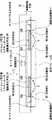
図4は、A−A線における電子機器の断面構造例である。図5は、図4の断面構造例の一部を拡大している。
図4と図5において、タッチパネル15と支持フレーム25の間には、上述した4つのバイモルフ型圧電アクチュエータ20が配置されている。タッチパネル15と支持フレーム25の間隔を設定するために、タッチパネル支持材35が設けられている。このタッチパネル支持材35は、柔軟性がありかつ振動を吸収しない材料により作られており、タッチパネル15のたとえば4隅位置に位置している。
タッチパネル15と支持フレーム25の間の空間には、上述したバイモルフ型圧電アクチュエータ20が配置されている。このバイモルフ型圧電アクチュエータ20と振動伝達機構は、振動発生手段を構成している。バイモルフ型圧電アクチュエータ20の撓み変位による振動がタッチパネル15側に伝達されるようになっている。
【0038】
以下の説明では、バイモルフ型圧電アクチュエータ20は、単に圧電アクチュエータ20と略称して用いる。この圧電アクチュエータ20の一端部20Aと支持フレーム25の間には、第1支持部41が設けられている。同様にして圧電アクチュエータ20の他端部20Bと支持フレーム25の間には第2支持部42が設けられている。圧電アクチュエータ20の中間部分と、タッチパネル15の裏面の間には、第3支持部43が設けられている。
【0039】
図5では、第1支持部41、第2支持部42および第3支持部43が拡大して示されている。図5(A)と図4に示すように、圧電アクチュエータ20の振動変位はUで示している。この振動変位Uは、タッチパネル15と支持フレーム25に対して垂直方向、すなわちZ方向である。このZ方向は図3に示すX方向とY方向に対して直角の方向である。
【0040】
図4と図5(A)に示すように、圧電アクチュエータ20は、タッチパネル15と支持フレーム25の間において、第1支持部41から第3支持部43を用いて、3点により支持されている。第1支持部41乃至第3支持部43は、圧電アクチュエータ20が発生する振動を、タッチパネル15側に伝えるいわゆる上述した振動伝達機構37を構成している。
第1支持部41乃至第3支持部43は、図5(A)に示すように、それぞれナイフエッジ状の突起50と軟質の接着剤51から構成されている。第1支持部41乃至第3支持部43は、それぞれの地点において圧電アクチュエータ20の撓み変形(曲げ変形とも呼ぶ)の妨げにならないように、ナイフエッジ状の突起50を用いて圧電アクチュエータ20の面を支持している。すなわち第1支持部41の突起50は、支持フレーム25に対して圧電アクチュエータ20をR方向に回転可能に支持している。同様にして第2支持部42の突起50は、支持フレーム25に対して圧電アクチュエータ20をR方向に回転可能に支持している。第3支持部43の突起50は、タッチパネル15に対して圧電アクチュエータ20をR方向に回転可能に支持している。
【0041】
第1支持部41乃至第3支持部43の軟質の接着剤51は、それぞれの突起50を支持フレーム25とタッチパネル15にそれぞれ接着して位置ずれを起こさないようにするために用いている。
軟質の接着剤51の材質としては、硬質の材料である突起を接着しかつ圧電アクチュエータ20の撓み変位を減じることなくタッチパネル15側に伝えるような材質を採用できる。
この軟質の接着剤の材質としては、たとえばスチレン系エラストマー(KGゲル:YMG−80−BK(北川工業株式会社))である。
【0042】
図5(B)においては、突起50と軟質の接着剤51を示しており、軟質の接着剤51は破線で示している。
図4と図5に示す圧電アクチュエータ20が発生する振動変位UはZ方向に平行である。第1支持部41乃至第3支持部43においては、上述したようにナイフエッジ状の突起50を有して、接着剤51で固定されいることから、第1支持部41乃至第3支持部43では圧電アクチュエータ20はR方向に沿って回転方向Rにのみ移動の自由度を有しており、振動変位Uに沿ったZ方向には位置が拘束されている。
【0043】
次に、図6と図7を参照して圧電アクチュエータ20の構造例について説明する。
図6は圧電アクチュエータ20の構造を一部省略して図示している。
圧電アクチュエータ20は、いわゆるバイモルフ型の圧電アクチュエータである。このバイモルフ型の圧電アクチュエータは、バイモルフ型圧電振動子などとも呼んでいる。圧電アクチュエータ20は、概略的には第1アクチュエータユニット61と第2アクチュエータユニット62を積層して構成されている。
【0044】
第1アクチュエータユニット61と第2アクチュエータユニット62の構造はほぼ同じであり、それぞれ複数の圧電素子層63を有している。この圧電素子層63は、圧電素子64とこの圧電素子64の両面に形成された電極層65の3層から構成されている。この圧電素子層63は、素アクチュエータユニットとも呼んでいる。
したがって第1アクチュエータユニット61と第2アクチュエータユニット62は、それぞれ複数の圧電素子層63を積層することで構成されている。図6と図7の例では、第1アクチュエータユニット61と第2アクチュエータユニット62は、それぞれ9層の圧電素子層63を積層して構成している。
圧電素子層63の圧電素子64は、たとえばPZT(チタン酸ジルコン酸鉛)により作られている。電極層65はたとえばAg−Pdにより作られている。第1アクチュエータユニット61と第2アクチュエータユニット62の間には、中間の電極層65Aが設けられている。
【0045】
したがって図6と図7に示す圧電アクチュエータ20は、合計18層の圧電素子64と、各圧電素子64の間の電極層65および表裏にある電極層65の合計19層の電極層65とから構成されている。図7に示す圧電素子64の1層当たりの厚さD1は、たとえば28μmである。電極層65の厚さD2は、たとえば約4μmである。圧電アクチュエータ20は、上述した圧電素子層63が18個積層された構造であり、各圧電素子層63はそれぞれ電気的に並列に結合されている。
【0046】
図6に示すように圧電アクチュエータ20に対して層間接続部66A,66Bを設け、これらの層間接続部66A,66Bに対して駆動電圧を印加した場合に、第1アクチュエータユニット61の9層の圧電素子層63が伸び/縮み、第2アクチュエータユニット62の9層の圧電素子層63が縮み/伸びるように、各圧電素子層63の圧電素子64は分極処理が施されている。
したがって、バイモルフ型圧電アクチュエータ20は、結果としてバイメタルと同様な原理で撓み変位するようになっている。図7に示す圧電アクチュエータ20の合計の厚みは、たとえば500μmであり、非常に薄く小型のものである。このような積層型の圧電アクチュエータ20を用いることにより、第1アクチュエータユニット61と第2アクチュエータユニット62をそれぞれ単層の圧電素子層で形成する場合に比べて、限られた駆動電圧を用いた場合により大きな撓み変位を発生させることができる。第1アクチュエータユニット61が伸びれば第2アクチュエータユニット62は縮み、第1アクチュエータユニット61が縮めば第2アクチュエータユニット62が伸びるといったように、圧電アクチュエータ20は図4に示す振動変位Uに沿って変位する。上述したこのバイモルフ型圧電アクチュエータ20は、多層バイモルフ型圧電アクチュエータとも呼んでいる。
【0047】
ここで、小型の携帯機器に特に適するバイモルフ型圧電アクチュエータ20の動作について述べる。
図1に示すような携帯の電子機器10は、通常Li−ionやNi−水素バッテリーを主電源として用いている。上述した通常のバイモルフ型圧電アクチュエータバッテリーに上記のバッテリーが発生する電圧を印加しても、使用者に触覚として知覚せしめるだけの撓み変位や力は発生できない。
この問題の解決のため、本発明の実施の形態では、構造を持つ多層のバイモルフ型圧電アクチュエータ20を用い、同じ撓み変位と力を発生させるために必要な駆動電圧の低電圧化を以下のように図る。
【0048】
バイモルフ型圧電アクチュエータ20を変形(駆動)するための圧電素子のひずみ量ΔL1は次式で与えられる。
ΔL1=d31*E*L(d31:圧電定数、E:印加電界強さ、L:素子長さ)
ひずみ量は電界の強さに比例するので、低電圧化しても電界強さを一定に保てれば歪み量は不変である。たとえば、図9(A)の素子には2V、図9(B)の素子には1Vの電圧が印加されているが、図9(B)の素子の厚さが図9(A)のそれの1/2である。このため、素子内部の電位勾配、すなわち電界強さは両方とも同じであり、結果としてひずみ量も同じである。
【0049】
このように、本発明では図6と図7のように素子を厚さ方向に分割することで、低電圧駆動でも使用者に触覚を感じさせるバイモルフ型圧電アクチュエータ20が実現できる。
この例の場合のアクチュエータ変位量を、たとえば20mmスパンで両端を支持したときの中央部変位として表現すると、印加電圧が10Vのとき、中央部変位は約25μmである。さらに素子の厚さを分割し、たとえばLi−ionバッテリーを用いた場合の電圧約3.3Vで上記と同様に25μm程度の変位を得るためには、1素子あたりの厚さを、図6の約1/3にすれば良いので、10μm程度にすれば実現する。
【0050】
図9に示す電子機器10の画像表示部30には、たとえば4つのアイコン31乃至34が表示されている。この画像表示部30の上には上述したタッチパネル15が配置されている。
【0051】
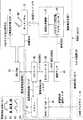
図10は、図9の制御ブロックの例を示している。
電子機器10の制御ブロック70は、振動発生手段71、振動制御手段73、タッチパネル15、画像表示部30を有している。
CPU(中央処理装置)74は、電子機器10の本来の携帯情報端末としての機能を実現するための中央処理装置であり、このCPU74は、画像表示部30とタッチパネル15などの信号処理を行う。すなわちCPU74は、画像表示部30に対してアイコンなどの表示信号S5を送り、タッチパネル15からの座標値S4がCPU74に供給されるようになっている。タッチパネル15は使用者の指Fまたはスタイラス(ペン)で接触して押すようになっている。
【0052】
振動制御手段73は、情報の種類に応じて異なる振動モードを振動発生手段71に発生させるためのものである。この振動制御手段73と振動発生手段71は、通常用いられている電子機器10には無い本発明の実施の形態の特徴的な部分である。
振動制御手段73は、プロセッサ80、メモリー81、外部プログラムポート82、D/Aコンバータ83、そして電流アンプ84を有している。プロセッサ80は、CPU74とメモリー81と外部プログラムポート82およびD/Aコンバータ83に接続されている。
【0053】
メモリー81は図10に示すようなたとえば4つの振動モードである、たとえば振動制御波形パターンP1乃至P4を記憶している。この振動制御波形パターンP(P1乃至P4)は、メモリー81からプロセッサ80に供給できる。これらの振動制御波形パターンP1乃至P4は、図9に示すアイコン31乃至34にそれぞれ対応したパターンである。アイコン31乃至34はそれぞれ異なる情報の例であり、この4種類のアイコン31乃至34は画像表示部30に任意に表示することができる。
【0054】
このデジタル信号である振動制御波形パターンPはプロセッサ80に供給される。メモリー81に対してデジタル信号である振動制御波形パターンPを供給させる方法としては、外部のパーソナルコンピュータなどの外部プログラマ75によって生成された任意の振動制御波形パターンを、外部プログラムポート82を介してプロセッサ80に取り込み、振動制御波形パターンPの登録番号および性質を付与した上でメモリー81に登録させる方法がある。
また、メモリー81に振動制御波形パターンを記憶させる別の方法としては、タッチパネル15から入力される波形の情報に基づいて、プロセッサ80は振動制御波形パターンを生成して、やはり登録番号と性質を付与した上でメモリー81に供給させる。
このように、外部プログラムポート82は、外部のパーソナルコンピュータやその他の外部的な手段により生成された上述したような振動制御波形パターンをプロセッサ80を介してメモリー81に取り込むためのポートである。
【0055】
プロセッサ80は、CPU74から送られるたとえばタッチパネル15上の座標値S4(座標情報)に応じた要求信号座標値Sにより、メモリー81からその要求信号座標値Sに応じた振動制御波形パターンP(P1〜P4)を選択して、デジタル波形S1としてD/Aコンバータ83に出力する信号処理を行う。この座標値S4(座標情報)は、図9に示す画像表示部30の情報としてのアイコン31乃至34の座標とリンクしている。
またプロセッサ80は、すでに述べたように外部的なプログラム手段を用いずに、携帯情報端末としての電子機器10に蓄えられているタッチパネル15などの入力手段により入力された情報により、振動発生手段71の圧電アクチュエータ20を動作させる振動波形制御パターンPを生成するなどの信号処理を行うこともできる。
このようにプロセッサ80とCPU74の間では、座標値S4に応じた要求信号座標値Sをやり取りすることにより、タッチパネル15の座標値S4をプロセッサ80に取り込むことができる。
【0056】
プロセッサ80は、D/Aコンバータ83に対してデジタル波形S1を送ると、D/Aコンバータ83はこのデジタル波形S1を、アナログ電圧波形S2に変換する。電流アンプ84は、このアナログ電圧波形S2を、圧電アクチュエータ20に対して圧電アクチュエータ20を駆動するために十分な電流を持った電圧の指令値S3を生成して振動発生手段71の圧電アクチュエータ20に送る。この電流アンプ84は、アナログ電圧波形S2を、圧電アクチュエータ20を駆動するために十分な電流になるように電流的に増幅して圧電アクチュエータ20に出力するのである。
【0057】
図10に示す振動発生手段71は、圧電アクチュエータ20と振動伝達機構37を有している。
振動伝達機構37は、図4に示すように第1支持部41乃至第3支持部43を有していることは既に述べている。圧電アクチュエータ20は、電流アンプ84からの指令値S3を機械的な撓み変位に変換する。振動伝達機構37は、圧電アクチュエータ20の撓み変位を図4に示すタッチパネル15に対して伝える。
図1と図3に示す携帯型情報端末のような電子機器10は、図10の入出力装置100を有している。この入出力装置100は、図10に示すように画像表示部30、タッチパネル15、振動発生手段71および振動制御手段73を有している。
【0058】
次に、上述した入出力装置100を有する電子機器10の動作について説明する。
使用者は、図9に示すような画像表示部30のアイコン31乃至34を一例として見ている。これらのアイコン31乃至34は、それぞれ異なる情報を示している。
使用者がアイコン31をタッチパネル15を介して指で触れると、画像表示部30の画面上の座標が図10に示すタッチパネル15から座標値S4としてCPU74に送られる。アイコン31とこのアイコン31の座標値S4は予めCPU74内で関係付けられている。
CPU74から使用者が触れたアイコン31を示す信号(たとえばクリックアイコン)が要求信号座標値Sとしてプロセッサ80に送られると、プロセッサ80はそのアイコン31に適した振動制御波形パターンP1をメモリー81から呼び出して、デジタル波形S1としてD/Aコンバータ83に出力する。
【0059】
D/Aコンバータ83は、プロセッサ80からのデジタル波形S1をアナログ電圧波形S2に変換する。電流アンプ84は、アナログ電圧波形S2の電流値を増幅して、指令値S3を圧電アクチュエータ20に供給する。圧電アクチュエータ20は、与えられた指令値S3(電圧値)に従い機械的に撓み曲げ変形をする。
この時に、圧電アクチュエータ20は、図4に示すように第1支持部41乃至第3支持部43によっては撓み曲げ変形を阻害することの無いように自由度を持っている。すなわち上述したように、第1支持部41乃至第3支持部43は、図5(A)に示すようにR方向に沿って回転方向には自由度を有しているが、振動変位U方向には位置変位はしないようになっている。このことから、圧電アクチュエータ20が撓み変形することによって、タッチパネル15は振動変位Uに沿ってのみ変位するのである。圧電アクチュエータ20の中央部の連続的なこのような振動変位Uは、タッチパネル15の連続的な変位に似てすなわち振動の波形として使用者の指Fに触覚フィードバックTBとして提示されることになる。
【0060】
このようにして、本発明の実施の形態では、タッチパネルに触覚(振動)を利用した触覚フィードバック発生機能を付加することにより、入力操作に対するフィードバックを触覚で実現できる。この触覚によるフィードバックは、従来から操作のフィードバックとして一般的に用いられている、クリック感やストローク感などと感覚的に近いものであり、使用者からみて画像や音によるフィードバックに比較して、より直感的であるという利点がある。そして、フィードバック情報だけでなく、触覚情報の表示機能もある。
【0061】
図9に示す別のアイコン32を選択することにより、上述したような同じ要領で、振動制御波形パターンP2がメモリー81から呼び出されて電流アンプ84からの指令値S3に基づいて圧電アクチュエータ20が振動制御波形パターンP2に基づいて振動する。
同様にしてアイコン33を使用者が指で押すことにより、振動制御波形パターンP3に基づいて圧電アクチュエータ20が振動変位を起こす。使用者がアイコン34を押すことにより、振動制御波形パターンP4に基づいて圧電アクチュエータ20が振動変位を起こす。
【0062】
図9に示すように、振動制御波形パターンP1は、クリック感、すなわち剛性感を発生するいわゆる矩形波パターンである。振動制御波形パターンP2は、ハートビートのようなリズム感覚を感じるようなデジタル波形であり、そのパルス幅は任意に設定されている。
振動制御波形パターンP3は、連続的な動きを発生する動作感を感じるような波形であり、階段状の波形である。振動制御波形パターンP4は、普通のタッチパネルの反応、すなわちほぼ一定の振動変位である。
このように、アイコン31乃至34は、それぞれ異なる情報を表示しているが、これらのアイコン31乃至34に応じて、異なる振動制御波形パターンP1乃至P4をそれぞれ割り付けている。このことから、振動制御波形パターンP1乃至P4に基づいて圧電アクチュエータ20が異なる振動変位を起こすことにより、使用者は指を通じてアイコン31乃至34の種類を直感的かつ体感的に感じることができるのである。
なお、アイコン31乃至34とそれらの座標値とそして振動制御波形パターンの関連付けは、図10に示すプロセッサ80で行うようにしてもよい。CPU74とプロセッサ80の信号処理の分担はいろいろ考えられるが、上述した図10に示す例に特に限定されるものでもない。
【0063】
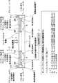
図11と図12は、本発明のさらに別の実施の形態を示している。
図11と図12のそれぞれの別の実施の形態は、図4の実施の形態に対してさらに付加的な要素を有している。
図11の実施の形態と図12の実施の形態の構成要素が、図4の実施の形態と同様な構成要素については、同じ符号を記してその説明を用いることにする。
【0064】
図11の実施の形態で異なるのは、タッチパネル15と支持フレーム25との間に、パネル押えフレーム110が設けられていることである。このパネル押えフレーム110は、タッチパネル15の端部を支持フレーム25に対して固定するためのほぼ断面L字型の部材であり、たとえば4辺を有する枠体である。
このパネル押えフレーム110の上端部111とタッチパネル15の端部の間には、ダストシール113が設けられている。このダストシール113は、たとえばリング状であり、ほぼ断面方形状、断面円形状もしくは断面楕円形状の弾力性を有する部材であり、たとえばプラスチックやゴムにより作られている。
このダストシール113は、タッチパネル15と支持フレーム25の間の空間に塵埃やごみなどのダストが侵入するのを防止するためのシールである。しかもこのダストシール113は、タッチパネル15をパネル押えフレーム110に対して支持するためのタッチパネル支持材の役割も果たしている。ダストシール113は、非常に柔軟性を持った材料か、ある程度柔軟性と振動を減衰しない特性を持った材料で作られており、圧電アクチュエータ20の発生する振動変位の減衰を最小にする作用を持つ。
【0065】
図12のさらに別の実施の形態では、図11のダストシール113およびパネル押えフレーム110に加えて圧電アクチュエータ20の振動伝達機構137の構造が異なっている。
図4では、第1支持部41乃至第3支持部43を用いて圧電アクチュエータ20がタッチパネル15と支持フレーム25の間に3点で支持されている。
これに対して図12の実施の形態では、振動伝達機構137は、支持部141ともう1つの支持部142を有している。支持部141は、圧電アクチュエータ20の一端部20Aと支持フレーム25の間に配置されている。もう1つの支持部142は、圧電アクチュエータ20の他端部20Bとタッチパネル15の内面の間に配置されている。
支持部142は、図5(A)と図5(B)の突起50と軟質の接着剤51を有する構成例と同じである。しかし、支持部141は、硬質の接着剤により画像表示部の支持フレーム25に堅固に固定されている。
このように圧電アクチュエータ20は、支持部141,142を用いた2点支持でタッチパネル15と支持フレーム25の間に支持されている。圧電アクチュエータ20が撓み変位すると、タッチパネル15は振動変位Uに沿って変位する。このような圧電アクチュエータ20はいわゆる片持ち式でタッチパネル15と支持フレーム25の間に支持されている。
【0066】
次に、図13と図14は、本発明のさらに別の実施の形態を示している。
図13の実施の形態では、圧電アクチュエータ20が、タッチパネル15の内面側のみに支持されていることが特徴的である。圧電アクチュエータ20の一端部20Aは、支持部241により支持されており、圧電アクチュエータ20の他端部20Bは、支持部242を用いて支持されている。このような構造を採用しても、圧電アクチュエータ20はR方向に沿って回転方向に自由度を有しているが、振動変位Uに沿ってタッチパネル15に振動を発生させることができる。
【0067】
図14の実施の形態では、図13の実施の形態のさらに圧電アクチュエータ20の中間部分には錘250が固定されている。この錘250の慣性力が圧電アクチュエータ20の振動変位Uを起こす場合に発生する。圧電アクチュエータ20がタッチパネル15を押し上げる時の反力を、この錘250の慣性力が支えるので、圧電アクチュエータ20の撓み変位が効率良くタッチパネル15に伝達できるのである。
図13と図14のように圧電アクチュエータ20がタッチパネル15側のみに支持されるような構成を採用することにより次のようなメリットがある。すなわち、使用者がタッチパネル15を押した時の力が圧電アクチュエータ20に直接加わることが無いので、使用者が誤って過度の力でタッチパネル15を押してしまった場合でも、圧電アクチュエータ20へは外力負荷が加わらないことになる。
【0068】
図15は、図10の制御ブロック70のさらに別の実施の形態を示している。図15の制御ブロック70が図10の制御ブロック70と異なるのは、次の点である。
すなわち振動制御手段73は、A/Dコンバータ89を有していることである。このA/Dコンバータ89は、圧電アクチュエータ20の端子間の電圧S6を測定するためにこの電圧S6を取り込んでアナログ/デジタル変換してデジタル電圧S10をプロセッサ80に送る。
本発明の実施の形態では、圧電アクチュエータ20とタッチパネル15はたとえば図4に示すように直接繋がれているので、使用者がタッチパネル15を押す力はそのまま圧電アクチュエータ20に伝わる。したがって、圧電アクチュエータ20とタッチパネル15との係合部は力に応じて変位する。
圧電アクチュエータ20はこの変位を与えると、それに比例した起電力を生じる性質があるので、この起電力を測定することで使用者の指Fの操作力(押圧力)をプロセッサ80が知ることができる。このように使用者の指Fがタッチパネル15を押すことにより生じる押圧力Wに応じた圧電アクチュエータ20の電圧S6を、プロセッサ80がリアルタイムで測定することができることにより次のようなメリットがある。
【0069】
すなわち使用者の指Fがタッチパネル15を過度な力で操作した場合には、たとえばプロセッサ80がCPU74に指令して画像表示部30に対して過度な力による操作を示すアイコンの表示信号S5を供給して、画像表示部30にそのアイコンを表示させることで使用者に過度な力を加えていることの注意を促すことができる。
入力ペンを用いた手書き入力時などの使用者の操作力(筆圧)を測定して、使用者と対応させて記憶しておくことにより、使用者の特定(認証)ができる。
タッチパネル15から得られる座標の情報(2次元座標情報)と、使用者の操作力の情報とを組み合せて、3次元入力装置として動作させるようなことも考えられる。
【0070】
次に、図16は、ある特定の振動数に限った時に、タッチパネル15を効率良く振動させるための振動指令方式の例について示している。
タッチパネル15およびその第1〜第3支持部41,42,43のすべてを1つの振動系として考えたとき、タッチパネル15の質量をm、タッチパネル15と係合している全ての部材の、バネ定数をKt、粘性係数をCtとすると、系の固有振動数fは次式で与えられる。
f=1/2π*(Kt/m−(Ct/2m))1/2
図10の振動制御手段73より、上記の固有振動数を含む振動波形を指令値として出力することにより、タッチパネル15を効率良く振動させることができる。ここで固有振動数を含む振動波形とは正弦波等の連続的な振動だけでなく、インパルス的な加振のように様々な振動数成分が複合したものの場合もある。なお、系の固有振動数を人間が触覚を感知しやすい50Hz〜300Hzくらいの範囲に調整するためには、タッチパネルの支持部等の材料や形状等を変更して、上述のバネ定数Ktや粘性係数Ctを適当な値にすれば良い。
【0071】
バイモルフ型圧電アクチュエータの圧電素子層は、好ましくは4層以上ある多層バイモルフ型圧電アクチュエータが好ましい。特に、PDAなどの携帯機器を考えた場合、駆動電圧の制約から通常の圧電アクチュエータは使用できない。圧電層を多層化することにより比較的低電圧で駆動が可能なアクチュエータを実現しそれをタッチパネルへの触覚フィードバックに使うことで、携帯機器においても触覚フィードバックのあるタッチパネルが実現できた。
バイモルフ型圧電アクチュエータの両端部および中央部の各支持部は、回転方向には自由度があり、触覚を伝える方向(アクチュエータ中央部の変位の方向)を拘束する。
触覚を伝える方向の拘束としてアクチュエータの変形を妨げないような点または線状の突起を用い、アクチュエータとその支持体との接合のためには軟質の接着剤を用いる。
【0072】
アクチュエータが発生する振動的変位(速度)を損なわないために、アクチュエータ自体をタッチパネルの支持体とする。
タッチパネルを支持する材料は、タッチパネルと画像表示部などの表示装置の間に埃等が侵入するのを防止するダストシールを兼ねている。
タッチパネルとその支持体を含めた振動系の固有振動数を人間が触知し易い周波数領域に設定し、かつその固有振動数そのもの/その振動数を含んだ振動でタッチパネルを加振することで、使用者には効率的に触覚フィードバックを与える。
【0073】
振動制御手段は1つまたは複数の制御パターン(振動波形)を記憶しており、使用者が選択するタッチパネル上の座標(通常アイコン等とリンクしている)に応じて適当な制御パターンを機器が選択し、アクチュエータを制御する。
この振動制御手段が記憶している制御パターンはソフトウェアによって定義されており、メーカーまたは使用者が任意に書き換えることが可能である。
振動制御手段は、アクチュエータに外力が加わることにより生じる起電力を検知する手段を備えており、使用者が入力操作を行うときの押圧力が測定できる。
【0074】
バイモルフ型圧電アクチュエータの片端部のみをベース等に固定し、もう一方の端部はタッチパネルと繋がっている構造も採用できる。
圧電アクチュエータが発生する振動的変位(速度)を損なわないために、ダンピング効果が少なくかつ柔軟な材料(たとえば 北川工業株式会社製のKGゲル)を介してタッチパネルを支持する。
圧電アクチュエータの曲げ変形を妨げないように、圧電アクチュエータは、タッチパネル下面に支持し、圧電アクチュエータが変位することで生じる振動をタッチパネルに伝える。この場合に、圧電アクチュエータの中央部には錘が付加されるようにしてもよい。
【0075】
バイモルフ型圧電アクチュエータを用いることで、携帯機器に適した小型(薄型)で低消費電力という特徴をもった触覚フィードバックシステムを構築できる。特に多層バイモルフ型圧電アクチュエータにすることで、上記の特徴の他、携帯機器で通常使われるLi−ion式やNi−水素式等のバッテリーを電源として動作する低電圧駆動型の触覚フィードバックシステムの構築が可能である。
簡素で安価な構造でバイモルフ型圧電アクチュエータの支持が実現する。
アクチュエータ自体がタッチパネルの支持体になるので、支持体による振動のロスがないばかりか、構造がシンプルになり安価なシステムを提供できる。
タッチパネルの支持部材がダストシールの機能も兼ねているので部材の点数を減らすことが可能で結果として安価なシステムを提供できる。
アクチュエータの出力を小さくしても使用者が触知できる振動を発生させることができるので、小型で安価なシステムを提供できる。
【0076】
入出力装置は、任意波形をもった振動(触覚)フィードバックが可能であるので、入力動作の確認としての操作感をはじめ、様々な触覚情報(感覚)を使用者に提供できる。この触覚情報は、視覚情報や聴覚情報に加えた第3の情報提示チャンネルとして活用することで、使用者に対してよりリアリティの高い、豊かな情報提供が可能である。さらに触覚は視覚や聴覚に比較して人間にとってより根源的な感覚であることを利用して、人間の感情を表現できる可能性もある。また、触覚フィードバックを単独で使うことも想定される。この場合は盲人への情報提示から、運転中や騒音環境下または何らかの状況により視覚・聴覚情報が期待できない場合に、いわゆるブラインド操作を可能にする。
振動波形を容易に書き換えたり、加えたりすることができるため、たとえば機器が使われる国ごとの振動波形の設定や、使用者の好みに合わせた振動パターンの設定が可能である。また、それぞれの使用者が作成した振動パターンをたとえばネットワークを介して他の使用者に提供することも可能である。
【0077】
使用者が機器をどのように使っているか状況がわかるので使用者による機器の破壊などを未然に防ぐことができる。また触覚を提示するために必要な部品と操作力を検知するための部品の大部分が共通で使えるので、安価な3次元入力デバイスを提供できる。
タッチパネルを支持する材料が柔軟性を持っているため圧電アクチュエータの発生する変位が機械的に抑制されることがなく、かつその材料が振動を吸収する特性(たとえばゴムのように)を小さくしてあるので、圧電アクチュエータの発生するエネルギーが効率良くタッチパネルに伝達できる。
使用者がタッチパネルを押したときの力が圧電アクチュエータに加わることがないので、使用者が誤って過度の力でタッチパネルを押してしまった際も圧電アクチュエータへの外力負荷がない。
錘の慣性力が、圧電アクチュエータがタッチパネルを押し上げる時の反力を支えるので、圧電アクチュエータの変位が効率よくタッチパネルに伝達できる。
【0078】
ところで本発明は上述した実施の形態に限定されるものではない。
バイモルフ型圧電アクチュエータ20の第1アクチュエータユニットと第2アクチュエータユニットの積層構造の例としては、それぞれ9層の圧電素子層63を有している。しかしこの圧電素子層63の積層数は9層に限らず、複数層であればよく、好ましくは4層以上であるとより大きな撓み変位を小さな駆動電圧で得ることができる。
図示の例では、第1支持部と第2支持部が画像表示部側に配置され、第3支持部がタッチパネル側に配置されているが、これに限らず第1支持部と第2支持部がタッチパネル側に配置され、かつ第3支持部が画像表示部側に配置されてもよい。
【0079】
本発明の実施の形態の電子機器は、一例として携帯情報端末(PDA)を例に挙げている。しかしこれに限らず本発明の入出力装置100を有する電子機器10は、携帯情報端末に限らず、携帯電話機、リモートコントローラ、DSC(デジタルスティルカメラ)、DVC(デジタルビデオコーダー)、PC(パーソナルコンピュータ)など、全てのタッチパネルを入力手段として備えている入出力装置を備える電子機器を含むものである。
【0080】
【発明の効果】
以上説明したように、本発明によれば、使用者がタッチパネルに対して触覚を利用して情報の入力操作を行う際に、情報の種類に応じた入力操作に対する使用者へのフィードバックを使用者に対する触覚で確実に実現することができる。
【図面の簡単な説明】
【図1】本発明の入出力装置を有する電子機器の好ましい実施の形態を示す斜視図。
【図2】図1の電子機器10のタッチパネルと支持フレームおよびバイモルフ型圧電アクチュエータを示す図。
【図3】図1の電子機器の分解斜視図。
【図4】図3の電子機器のA−A線における断面構造部。
【図5】図4の圧電アクチュエータ、振動伝達機構などを拡大して示す図。
【図6】バイモルフ型圧電アクチュエータの構造例を示しており、一部省略した斜視図。
【図7】図6のバイモルフ型圧電アクチュエータの積層構造例を示す図。
【図8】バイモルフ型圧電アクチュエータが単層の場合と複数層の場合の比較例を示す図。
【図9】画像表示部に一例として表示されたアイコンおよびそれらのアイコンに対応する振動制御波形パターンの例を示す図。
【図10】入出力装置を含む制御ブロックを示す図。
【図11】本発明の別の実施の形態を示す断面図。
【図12】本発明のさらに別の実施の形態を示す断面図。
【図13】本発明のさらに別の実施の形態を示す断面図。
【図14】本発明のさらに別の実施の形態を示す断面図。
【図15】図10に対応して示す制御ブロックの別の実施の形態を示す図。
【図16】本発明のバイモルフ型圧電アクチュエータにおいてある特定の振動子に限った時に、タッチパネルを効率良く振動させるための振動指令方式の例を示す図。
【符号の説明】
10・・・電子機器、15・・・タッチパネル、20・・・バイモルフ型圧電アクチュエータ(圧電アクチュエータ)、25・・・支持フレーム、30・・・画像表示部、31乃至34・・・アイコン(画像表示部に表示される情報の一例)、37・・・振動伝達機構、41・・・第1支持部、42・・・第2支持部、43・・・第3支持部、50・・・支持部の突起、51・・・支持部の軟質の接着剤、61・・・圧電アクチュエータの第1アクチュエータユニット、62・・・圧電アクチュエータの第2アクチュエータユニット、63・・・圧電素子層、64・・・圧電素子、65・・・電極層、71・・・振動発生手段、73・・・振動制御手段、113・・・ダストシール、P1乃至P4・・・振動制御波形パターン、U・・・振動変位[0001]
TECHNICAL FIELD OF THE INVENTION
The present invention relates to an input / output device and an electronic apparatus having the input / output device that can realize, when a user touches a touch panel to input information by touching the touch panel, feedback to the user of the input operation by touch. is there.
[0002]
[Prior art]
As an example of an electronic device, for example, an ATM (automatic teller machine) is provided with a touch panel on a display surface of the ATM. When a user inputs information via a touch panel, feedback to the user when the user performs an input operation is realized by a device external to the ATM. This additional device is realized by, for example, causing a change in an image on a display screen of an ATM or a change in sound by a speaker, a sounder, or the like.
[0003]
[Problems to be solved by the invention]
In such a feedback method based on a change in an image or a change in sound in an input operation, when a small electronic device such as a portable information terminal is used outdoors, sufficient feedback is provided in an environment such as noise or darkness. Is difficult to communicate to the user.
Further, when the user points an icon or the like on the display screen with a finger, there is also a problem that the finger that performs the operation hides the image, and feedback information due to a change in the image is not transmitted to the user.
[0004]
Some attempts to provide some form of tactile feedback to a touch panel include the following documents that have already been published.
In the coordinate input device disclosed in Japanese Patent Application Laid-Open No. 9-251347, a click feeling is provided by a combination of a touch panel and a mechanical switch.
The information display device and the operation input device disclosed in Japanese Patent Application Laid-Open No. H11-212725 include a description that presents tactile feedback to a touch panel using a piezoelectric element or the like. Unless a stacked piezoelectric element or a bimorph piezoelectric element is used, the displacement is too small to be realized.
In the touch panel switch disclosed in Japanese Utility Model Application Laid-Open No. 63-164127, there is a description that a haptic feedback is given to the touch panel by using a piezoelectric body, but the touch panel is limited to an optical touch panel.
The display device disclosed in Japanese Patent Application Laid-Open No. H11-85400 is a combination of an image display, an input device, and a vibration device. There is no specific description such as the type of the actuator and the supporting method. It mainly describes a structure in which an input detection sensor (opaque) is arranged below the image display device.
Therefore, the present invention solves the above-described problems, and when a user performs an input operation of information using a tactile sense on a touch panel, feedback to the user on the input operation according to the type of information is provided to the user using a tactile It is an object of the present invention to provide an input / output device and an electronic apparatus having the input / output device, which can be reliably realized by the above.
[0005]
[Means for Solving the Problems]
The invention according to
[0006]
According to
The vibration generating means is arranged on the image display unit. The vibration generating means feeds back different types of tactile feedback to the user through the touch panel according to the type of information.
The vibration control means causes the vibration generation means to generate different vibrations according to the type of information.
The vibration generating means has a first actuator unit and a second actuator unit. The first actuator unit and the second actuator unit are stacked, and a bimorph type piezoelectric actuator in which one of the first actuator unit and the second actuator unit expands and one contracts is used as the vibration generating means.
The first actuator unit and the second actuator unit are both formed by laminating a plurality of piezoelectric element layers.
[0007]
Thereby, the vibration generating means generates different vibrations according to the type of information based on the vibration from the vibration control means. Thus, by selecting and touching one of the different pieces of information on the image display unit through the touch panel, it is possible to feed back a vibration corresponding to the type of the information to the user as a tactile sensation to the user. Therefore, the user can intuitively know the type of information on the image display unit according to the type of touch.
According to the present invention, by adding a display function using tactile sense (vibration) to the touch panel, feedback to an input operation can be realized by tactile sense. This tactile feedback is intuitively similar to a click feeling or a stroke feeling that has been commonly used as operation feedback in the past, and is more intuitive than image or sound feedback. There is an advantage that there is.
In addition, by combining the tactile display function with a display function that has been conventionally used such as video and sound, it is possible to display information with higher reality.
Further, since the first actuator unit and the second actuator unit of the bimorph type piezoelectric actuator are both formed by laminating a plurality of piezoelectric element layers, each actuator unit is made of a single piezoelectric element layer. In comparison with the above, the bending (bending) displacement in the vibration direction can be increased.
[0008]
According to a second aspect of the present invention, in the input / output device according to the first aspect, electrodes are arranged on both sides of each of the piezoelectric elements of the first actuator unit and the second actuator unit.
[0009]
According to a third aspect of the present invention, in the input / output device according to the first aspect, the bimorph-type piezoelectric actuator is disposed between one end of the bimorph-type piezoelectric actuator and the image display unit; A second support portion disposed between the other end portion of the bimorph type piezoelectric actuator and the image display portion, and a third support portion disposed between a center portion of the bimorph type piezoelectric actuator and the touch panel. Have.
[0010]
According to the third aspect, the bimorph piezoelectric actuator has a first support, a second support, and a third support. The first support is disposed between one end of the bimorph piezoelectric actuator and the image display. The second support is disposed between the other end of the bimorph type piezoelectric actuator and the image display. The third support is disposed between the center of the bimorph piezoelectric actuator and the touch panel. For this reason, the bimorph type piezoelectric actuator is supported at three points between the touch panel and the image display unit.
[0011]
According to a fourth aspect of the present invention, in the input / output device according to the third aspect, the first support, the second support, and the third support rotate differently from a direction in which the user contacts the touch panel. It has a degree of freedom in the direction.
[0012]
According to the fourth aspect, the first support portion, the second support portion, and the third support portion have a degree of freedom in a rotation direction different from a direction in which the user contacts the touch panel. For this reason, even if the bimorph-type piezoelectric actuator is bent and displaced, the bimorph-type piezoelectric actuator can freely rotate in the rotation direction in the first to third support portions.
[0013]
According to a fifth aspect of the present invention, in the input / output device according to the fourth aspect, the first support portion and the second support portion are provided with the projections with respect to the bimorph-type piezoelectric actuator and the image display unit. The third support portion includes a protrusion, and a soft adhesive for fixing the protrusion to the bimorph piezoelectric actuator and the touch panel.
[0014]
According to the fifth aspect, the first support portion and the second support portion have a protrusion and a soft adhesive. The soft adhesive between the first support portion and the second support portion is for fixing the protrusion to the bimorph type piezoelectric actuator and the image display portion. The projection supports the bimorph-type piezoelectric actuator and is fixed by a soft adhesive. Therefore, the bimorph-type piezoelectric actuator has a degree of freedom in the rotation direction at the first support portion and the second support portion. Therefore, the movement is restricted in the direction in which the user contacts.
The third support has a protrusion and a soft adhesive. The soft adhesive fixes the protrusion to the bimorph type piezoelectric actuator and the touch panel. The projection supports the bimorph type piezoelectric actuator so that it has a degree of freedom in the rotational direction and can restrain the position in the direction in which the user contacts the finger.
[0015]
According to a sixth aspect of the present invention, in the input / output device according to the first aspect, the bimorph-type piezoelectric actuator includes a portion between one end of the bimorph-type piezoelectric actuator and the touch panel and another end of the bimorph-type piezoelectric actuator. And a support portion respectively disposed between the touch panel and the touch panel.
[0016]
According to claim 6, the bimorph type piezoelectric actuator has a support portion. The support portions are arranged at two places between one end of the bimorph type piezoelectric actuator and the touch panel, and at two places between the other end of the bimorph type piezoelectric actuator and the touch panel. Therefore, the bimorph type piezoelectric actuator is supported at two points on the touch panel side by the two supporting portions. This support does not hinder the bending deformation of the piezoelectric actuator.
[0017]
According to a seventh aspect of the present invention, in the input / output device according to the sixth aspect, a weight is provided in the middle of the bimorph piezoelectric actuator.
[0018]
In claim 7, a weight is provided in the middle of the bimorph type piezoelectric actuator. The reaction force generated in the support portion due to the bending of the actuator is increased.
[0019]
The invention according to claim 8 is the input / output device according to
[0020]
In claim 8, the image display unit is a liquid crystal display unit. The dust seal prevents dust from entering between the touch panel and the liquid crystal display.
[0021]
According to a ninth aspect of the present invention, in the input / output device according to the first aspect, the vibration control means stores a plurality of vibration control waveform patterns for the bimorph type piezoelectric actuator, and each of the vibration control waveform patterns Corresponds to the plurality of pieces of information displayed on the image display unit.
[0022]
According to a tenth aspect of the present invention, in the input / output device according to the ninth aspect, the vibration control waveform pattern stored in the vibration control means is rewritable.
[0023]
In claim 10, the vibration control waveform pattern can be arbitrarily rewritten.
[0024]
According to an eleventh aspect of the present invention, in the input / output device according to the ninth aspect, the vibration control means detects an electromotive force generated according to a pressing force of the user applied to the bimorph type piezoelectric actuator. It has power detection means.
[0025]
In claim 11, the electromotive force detecting means detects the user's pressing force applied to the bimorph-type piezoelectric actuator, and thus detects the user's pressing force by detecting the electromotive force generated from the bimorph-type piezoelectric actuator. It can be measured in real time. By measuring the pressing force of the user, the user can be alerted when excessive pressing force is applied.
[0026]
The invention according to claim 12 is an electronic device having an input / output device for inputting / outputting information, wherein the input / output device displays an image on a display unit for displaying information and the information on the image display unit. A touch panel for inputting / outputting the information by a user touching a portion corresponding to a position where the touch panel is located, the touch panel being arranged on the image display unit, and providing different types of tactile sensations through the touch panel depending on the type of the information. A vibration generating means for feeding back to the user; and a vibration control means for causing the vibration generating means to generate different vibrations according to the type of the information, wherein the vibration generating means comprises a first actuator unit. And a second actuator unit stacked on the first actuator unit. The first actuator unit and the second actuator unit A first actuator unit and a second actuator unit, each of which is formed by laminating a plurality of piezoelectric element layers. An electronic device having an output device.
[0027]
In claim 12, the image display unit displays information. The touch panel performs input / output of information by a user touching a portion of the image display unit corresponding to a position where information is displayed.
The vibration generating means is arranged on the image display unit. The vibration generating means feeds back different types of tactile feedback to the user through the touch panel according to the type of information.
The vibration control means causes the vibration generation means to generate different vibrations according to the type of information.
The vibration generating means has a first actuator unit and a second actuator unit. The first actuator unit and the second actuator unit are stacked, and a bimorph type piezoelectric actuator in which one of the first actuator unit and the second actuator unit expands and one contracts is used as the vibration generating means.
The first actuator unit and the second actuator unit are both formed by laminating a plurality of piezoelectric element layers.
Thereby, the vibration generating means generates different vibrations according to the type of information based on the vibration from the vibration control means. Thus, by selecting and touching one of the different pieces of information on the image display unit through the touch panel, it is possible to feed back a vibration corresponding to the type of the information to the user as a tactile sensation to the user. Therefore, the user can intuitively know the type of information on the image display unit according to the type of touch.
[0028]
According to the present invention, by adding a display function using tactile sense (vibration) to the touch panel, feedback to an input operation can be realized by tactile sense. This tactile feedback is intuitively similar to a click feeling or a stroke feeling that has been commonly used as operation feedback in the past, and is more intuitive than image or sound feedback. There is an advantage that there is.
Further, since the first actuator unit and the second actuator unit of the bimorph type piezoelectric actuator are both formed by laminating a plurality of piezoelectric element layers, each actuator unit is made of a single piezoelectric element layer. In comparison with the above, the bending (bending) displacement in the vibration direction can be increased.
[0029]
According to a thirteenth aspect of the present invention, in the electronic device having the input / output device according to the twelfth aspect, electrodes are arranged on both sides of each of the piezoelectric elements of the first actuator unit and the second actuator unit.
[0030]
BEST MODE FOR CARRYING OUT THE INVENTION
Hereinafter, preferred embodiments of the present invention will be described in detail with reference to the accompanying drawings.
The embodiments described below are preferred specific examples of the present invention, and therefore, various technically preferable limitations are given. However, the scope of the present invention particularly limits the present invention in the following description. It is not limited to these forms unless otherwise stated.
[0031]
FIG. 1 is a perspective view showing an example of an electronic apparatus having the input / output device of the present invention. The electronic device 10 shown in FIG. 1 is a so-called portable information terminal (PDA).
According to the present invention, by adding a tactile feedback generation function using tactile sense (vibration) to the touch panel, it is possible to provide a user with tactile feedback to an input operation according to the type of information. This tactile feedback is intuitively similar to a click feeling or a stroke feeling that has been generally used as operation feedback in the past, and is more user-friendly than image or sound feedback. It has the advantage of being intuitive.
Further, the tactile feedback generation function can present various information to the user in addition to the feedback of the input operation as well as the conventionally used display of images and sounds.
[0032]
The electronic device 10 illustrated in FIG. 1 roughly includes a main body 13, a
The main body 13 has
[0033]
FIG. 2 shows the
[0034]
FIG. 3 is an exploded perspective view showing the
The main body 13 has the support frame 25 of the image display unit and the
The
The support frame 25 is made of, for example, metal, and is a four-sided frame provided at four sides of the
[0035]
The main body 13 is made of, for example, plastic, for example, PC (polycarbonate), ABS (acrylonitrile butadiene styrene), PI (polyimide), etc., but is not particularly limited.
The support frame 25 can be made of metal or plastic, but is made of, for example, aluminum, iron plate, or stainless plate. The
[0036]
The
The
When a user (also called an operator) presses the surface of the polyester film with a finger, a current flows through the conductive film of one polyester film and the conductive film of the other polyester film, and the intersection of X and Y on the coordinate axis Thus, it is possible to know which position of the
By processing the current flowing by connecting the intersections with an electric circuit, for example, the CPU (central processing unit) determines which icon 31 to 34 of the
The type of the
[0037]
FIG. 4 is an example of a cross-sectional structure of the electronic device taken along line AA. FIG. 5 is an enlarged view of a part of the example of the sectional structure of FIG.
4 and 5, between the
In the space between the
[0038]
In the following description, the bimorph
[0039]
In FIG. 5, the first support portion 41, the second support portion 42, and the third support portion 43 are shown in an enlarged manner. As shown in FIGS. 5A and 4, the vibration displacement of the
[0040]
As shown in FIGS. 4 and 5A, the
As shown in FIG. 5A, the first to third support portions 41 to 43 are each composed of a knife-edge-shaped
[0041]
The
As a material of the
The material of the soft adhesive is, for example, a styrene-based elastomer (KG gel: YMG-80-BK (Kitagawa Kogyo Co., Ltd.)).
[0042]
In FIG. 5B, the
The vibration displacement U generated by the
[0043]
Next, an example of the structure of the
FIG. 6 shows the structure of the
The
[0044]
The structures of the first actuator unit 61 and the second actuator unit 62 are substantially the same, each having a plurality of piezoelectric element layers 63. The
Therefore, the first actuator unit 61 and the second actuator unit 62 are each formed by stacking a plurality of piezoelectric element layers 63. In the examples of FIGS. 6 and 7, the first actuator unit 61 and the second actuator unit 62 are each configured by laminating nine piezoelectric element layers 63.
The
[0045]
Therefore, the
[0046]
As shown in FIG. 6, when the interlayer connecting portions 66A and 66B are provided for the
Therefore, the bimorph
[0047]
Here, the operation of the bimorph
The portable electronic device 10 as shown in FIG. 1 normally uses a Li-ion or Ni-hydrogen battery as a main power supply. Even if a voltage generated by the battery is applied to the normal bimorph-type piezoelectric actuator battery described above, no bending displacement or force that can be perceived as tactile by the user cannot be generated.
In order to solve this problem, in the embodiment of the present invention, a multilayer bimorph
[0048]
The strain amount ΔL1 of the piezoelectric element for deforming (driving) the bimorph
ΔL1 = d31 * E * L (d31: piezoelectric constant, E: applied electric field strength, L: element length)
Since the amount of distortion is proportional to the strength of the electric field, even if the voltage is reduced, the amount of distortion remains unchanged if the strength of the electric field is kept constant. For example, a voltage of 2 V is applied to the element of FIG. 9A and a voltage of 1 V is applied to the element of FIG. 9B, but the thickness of the element of FIG. It is 1/2 of. Therefore, the potential gradient inside the element, that is, the electric field strength is the same for both, and as a result, the strain amount is also the same.
[0049]
As described above, in the present invention, by dividing the element in the thickness direction as shown in FIGS. 6 and 7, it is possible to realize the bimorph
If the amount of actuator displacement in this example is expressed as a central portion displacement when both ends are supported at a span of 20 mm, for example, when the applied voltage is 10 V, the central portion displacement is about 25 μm. In order to further divide the element thickness and obtain a displacement of about 25 μm at a voltage of about 3.3 V when a Li-ion battery is used in the same manner as described above, the thickness per element must be as shown in FIG. Since it may be reduced to about 1/3, it is realized when the thickness is reduced to about 10 μm.
[0050]
For example, four icons 31 to 34 are displayed on the
[0051]
FIG. 10 shows an example of the control block of FIG.
The control block 70 of the electronic device 10 includes a vibration generation unit 71, a
The CPU (Central Processing Unit) 74 is a central processing unit for realizing the function of the electronic device 10 as an original portable information terminal. The
[0052]
The vibration control means 73 causes the vibration generation means 71 to generate different vibration modes according to the type of information. The
The vibration control means 73 has a
[0053]
The
[0054]
The vibration control waveform pattern P, which is a digital signal, is supplied to the
As another method of storing the vibration control waveform pattern in the
As described above, the
[0055]
The
In addition, as described above, the
Thus, by exchanging the request signal coordinate value S corresponding to the coordinate value S4 between the
[0056]
When the
[0057]
The vibration generating means 71 shown in FIG. 10 includes the
It has already been described that the
An electronic device 10 such as the portable information terminal shown in FIGS. 1 and 3 has the input / output device 100 shown in FIG. The input / output device 100 includes an
[0058]
Next, an operation of the electronic device 10 including the above-described input / output device 100 will be described.
The user sees the icons 31 to 34 of the
When the user touches the icon 31 with a finger through the
When a signal (for example, a click icon) indicating the icon 31 touched by the user is sent from the
[0059]
The D /
At this time, as shown in FIG. 4, the
[0060]
As described above, in the embodiment of the present invention, by adding the tactile feedback generation function using the tactile sense (vibration) to the touch panel, the feedback to the input operation can be realized by the tactile sense. This tactile feedback is intuitively similar to a click feeling or a stroke feeling, which has been generally used as operation feedback in the past. It has the advantage of being intuitive. In addition, it has a function of displaying not only feedback information but also tactile information.
[0061]
By selecting another icon 32 shown in FIG. 9, in the same manner as described above, the vibration control waveform pattern P2 is called from the
Similarly, when the user presses the icon 33 with a finger, the
[0062]
As shown in FIG. 9, the vibration control waveform pattern P1 is a so-called rectangular wave pattern that generates a click feeling, that is, a rigid feeling. The vibration control waveform pattern P2 is a digital waveform that gives a rhythmic sensation like a heartbeat, and its pulse width is set arbitrarily.
The vibration control waveform pattern P3 is a waveform that gives a sense of operation that generates a continuous movement, and is a step-like waveform. The vibration control waveform pattern P4 is a response of an ordinary touch panel, that is, a substantially constant vibration displacement.
As described above, the icons 31 to 34 display different information, respectively, and different vibration control waveform patterns P1 to P4 are assigned according to the icons 31 to 34, respectively. Accordingly, the user can intuitively and intuitively feel the types of the icons 31 to 34 through the finger by causing the
Note that the association between the icons 31 to 34, their coordinate values, and the vibration control waveform pattern may be performed by the
[0063]
11 and 12 show still another embodiment of the present invention.
Each of the alternative embodiments of FIGS. 11 and 12 has additional elements to the embodiment of FIG.
The components of the embodiment of FIG. 11 and the embodiment of FIG. 12 which are the same as those of the embodiment of FIG. 4 are denoted by the same reference numerals, and the description thereof will be used.
[0064]
11 is that a panel holding frame 110 is provided between the
A dust seal 113 is provided between an
The dust seal 113 is a seal for preventing dust such as dust and dirt from entering the space between the
[0065]
12, the structure of the vibration transmission mechanism 137 of the
In FIG. 4, the
On the other hand, in the embodiment of FIG. 12, the vibration transmission mechanism 137 has a
The
As described above, the
[0066]
Next, FIG. 13 and FIG. 14 show still another embodiment of the present invention.
The embodiment of FIG. 13 is characterized in that the
[0067]
In the embodiment of FIG. 14, a weight 250 is fixed to an intermediate portion of the
The following advantages are obtained by adopting a configuration in which the
[0068]
FIG. 15 shows another embodiment of the control block 70 of FIG. The control block 70 of FIG. 15 differs from the control block 70 of FIG. 10 in the following point.
That is, the vibration control means 73 has an A /
In the embodiment of the present invention, since the
When the
[0069]
That is, when the user's finger F operates the
The user's operation force (pen pressure) at the time of handwriting input using the input pen or the like is measured and stored in association with the user, whereby the user can be specified (authenticated).
It is also conceivable to operate as a three-dimensional input device by combining information on coordinates (two-dimensional coordinate information) obtained from the
[0070]
Next, FIG. 16 shows an example of a vibration command method for efficiently vibrating the
When the
f = 1 / 2π * (Kt / m- (Ct / 2m))1/2
By outputting a vibration waveform including the above natural frequency as a command value from the vibration control means 73 in FIG. 10, the
[0071]
The piezoelectric element layer of the bimorph piezoelectric actuator is preferably a multilayer bimorph piezoelectric actuator having four or more layers. In particular, when a portable device such as a PDA is considered, a normal piezoelectric actuator cannot be used due to the restriction of the driving voltage. By making the piezoelectric layers multi-layered, an actuator that can be driven at a relatively low voltage was realized and used for haptic feedback to the touch panel, so that a touch panel with haptic feedback was also realized in portable devices.
The support portions at both ends and the center of the bimorph type piezoelectric actuator have a degree of freedom in the rotation direction, and constrain the direction of transmitting the tactile sensation (the direction of displacement of the actuator center).
A point or a linear projection that does not hinder the deformation of the actuator is used as a constraint on the direction of transmitting the tactile sensation, and a soft adhesive is used to join the actuator to its support.
[0072]
In order not to impair the vibrational displacement (speed) generated by the actuator, the actuator itself is used as a support for the touch panel.
The material that supports the touch panel also serves as a dust seal that prevents dust and the like from entering between the touch panel and a display device such as an image display unit.
By setting the natural frequency of the vibration system including the touch panel and its support in a frequency range where humans can easily touch, and by vibrating the touch panel with the natural frequency itself / vibration including the frequency, The user is effectively provided with tactile feedback.
[0073]
The vibration control means stores one or a plurality of control patterns (vibration waveforms), and the device generates an appropriate control pattern in accordance with coordinates on the touch panel (normally linked to an icon or the like) selected by the user. Select and control the actuator.
The control pattern stored in the vibration control means is defined by software, and can be arbitrarily rewritten by a manufacturer or a user.
The vibration control means includes means for detecting an electromotive force generated by an external force applied to the actuator, and can measure a pressing force when the user performs an input operation.
[0074]
A structure in which only one end of the bimorph type piezoelectric actuator is fixed to a base or the like, and the other end is connected to a touch panel can be adopted.
In order not to impair the vibrational displacement (velocity) generated by the piezoelectric actuator, the touch panel is supported via a soft material having a small damping effect (for example, KG gel manufactured by Kitagawa Industries Co., Ltd.).
The piezoelectric actuator is supported on the lower surface of the touch panel so as not to hinder the bending deformation of the piezoelectric actuator, and transmits vibration generated by displacement of the piezoelectric actuator to the touch panel. In this case, a weight may be added to the center of the piezoelectric actuator.
[0075]
By using the bimorph type piezoelectric actuator, a haptic feedback system having characteristics of small size (thinness) and low power consumption suitable for a portable device can be constructed. In particular, by using a multi-layer bimorph type piezoelectric actuator, in addition to the above features, a low-voltage driven haptic feedback system that operates using a battery of Li-ion type or Ni-hydrogen type commonly used in portable devices is constructed. Is possible.
A bimorph-type piezoelectric actuator can be supported with a simple and inexpensive structure.
Since the actuator itself serves as a support for the touch panel, not only is there no loss of vibration due to the support, but the structure is simple and an inexpensive system can be provided.
Since the support member of the touch panel also functions as a dust seal, the number of members can be reduced, and as a result, an inexpensive system can be provided.
Even if the output of the actuator is reduced, vibration that can be touched by the user can be generated, so that a small and inexpensive system can be provided.
[0076]
Since the input / output device is capable of performing vibration (tactile) feedback with an arbitrary waveform, the input / output device can provide the user with various tactile information (feelings) including an operational feeling as confirmation of an input operation. By utilizing the tactile information as a third information presentation channel in addition to the visual information and the auditory information, it is possible to provide the user with more realistic and rich information. Furthermore, there is a possibility that human emotions can be expressed by utilizing that tactile sense is more fundamental to humans than visual and auditory senses. It is also envisioned that haptic feedback may be used alone. In this case, a so-called blind operation is enabled when information on visual and auditory information cannot be expected during driving, in a noisy environment, or due to some conditions from information presentation to a blind person.
Since the vibration waveform can be easily rewritten or added, for example, it is possible to set a vibration waveform for each country where the device is used or to set a vibration pattern according to the user's preference. Also, the vibration pattern created by each user can be provided to other users via a network, for example.
[0077]
Since it is possible to know how the user uses the device, it is possible to prevent the device from being destroyed by the user. Further, since most of the components necessary for presenting the tactile sensation and the components for detecting the operation force can be used in common, an inexpensive three-dimensional input device can be provided.
Because the material supporting the touch panel has flexibility, the displacement generated by the piezoelectric actuator is not mechanically suppressed, and the material absorbs vibration (for example, rubber) to reduce its characteristics. Therefore, the energy generated by the piezoelectric actuator can be efficiently transmitted to the touch panel.
Since the force when the user presses the touch panel is not applied to the piezoelectric actuator, there is no external force load on the piezoelectric actuator even when the user accidentally presses the touch panel with excessive force.
Since the inertial force of the weight supports the reaction force when the piezoelectric actuator pushes up the touch panel, the displacement of the piezoelectric actuator can be efficiently transmitted to the touch panel.
[0078]
Incidentally, the present invention is not limited to the above-described embodiment.
As an example of the laminated structure of the first actuator unit and the second actuator unit of the bimorph
In the illustrated example, the first support unit and the second support unit are arranged on the image display unit side, and the third support unit is arranged on the touch panel side. However, the present invention is not limited to this, and the first support unit and the second support unit are not limited to this. May be arranged on the touch panel side, and the third support unit may be arranged on the image display unit side.
[0079]
An electronic device according to an embodiment of the present invention uses a personal digital assistant (PDA) as an example. However, the electronic device 10 having the input / output device 100 of the present invention is not limited to this, and is not limited to a portable information terminal, but may be a mobile phone, a remote controller, a DSC (digital still camera), a DVC (digital video coder), a PC (personal computer). ), Etc., including electronic devices provided with input / output devices provided with all touch panels as input means.
[0080]
【The invention's effect】
As described above, according to the present invention, when a user performs an input operation of information on a touch panel using a tactile sense, feedback to the user on an input operation according to the type of information is performed by the user. Can be reliably realized by the sense of touch.
[Brief description of the drawings]
FIG. 1 is a perspective view showing a preferred embodiment of an electronic apparatus having an input / output device of the present invention.
FIG. 2 is a diagram showing a touch panel, a support frame, and a bimorph type piezoelectric actuator of the electronic device 10 of FIG.
FIG. 3 is an exploded perspective view of the electronic device of FIG. 1;
FIG. 4 is a cross-sectional structure taken along line AA of the electronic device of FIG. 3;
FIG. 5 is an enlarged view showing a piezoelectric actuator, a vibration transmission mechanism, and the like in FIG. 4;
FIG. 6 is a perspective view showing an example of the structure of a bimorph type piezoelectric actuator, with a part thereof omitted;
FIG. 7 is a view showing an example of a laminated structure of the bimorph type piezoelectric actuator of FIG. 6;
FIG. 8 is a diagram showing a comparative example in a case where the bimorph type piezoelectric actuator has a single layer and a case where the bimorph piezoelectric actuator has a plurality of layers.
FIG. 9 is a diagram showing an example of icons displayed on the image display unit as examples and vibration control waveform patterns corresponding to those icons.
FIG. 10 is a diagram showing a control block including an input / output device.
FIG. 11 is a cross-sectional view showing another embodiment of the present invention.
FIG. 12 is a sectional view showing still another embodiment of the present invention.
FIG. 13 is a sectional view showing still another embodiment of the present invention.
FIG. 14 is a sectional view showing still another embodiment of the present invention.
FIG. 15 is a diagram showing another embodiment of the control block shown corresponding to FIG. 10;
FIG. 16 is a diagram showing an example of a vibration command system for efficiently vibrating the touch panel when the bimorph type piezoelectric actuator of the present invention is limited to a specific vibrator.
[Explanation of symbols]
DESCRIPTION OF SYMBOLS 10 ... Electronic device, 15 ... Touch panel, 20 ... Bimorph type piezoelectric actuator (piezoelectric actuator), 25 ... Support frame, 30 ... Image display part, 31-34 ... Icon (Image An example of information displayed on the display unit), 37: vibration transmitting mechanism, 41: first support unit, 42: second support unit, 43: third support unit, 50 ... Protrusion of support portion, 51 ... Soft adhesive of support portion, 61 ... First actuator unit of piezoelectric actuator, 62 ... Second actuator unit of piezoelectric actuator, 63 ... Piezoelectric element layer, 64 ... piezoelectric element, 65 ... electrode layer, 71 ... vibration generating means, 73 ... vibration control means, 113 ... dust seal, P1 to P4 ... vibration control waveform pattern, U ... vibration Place
Claims (13)
Translated fromJapanese前記画像表示部の前記情報を表示している位置に対応する部分へ使用者が接触することで前記情報の入出力を行うためのタッチパネルと、
前記画像表示部に配置されて、前記情報の種類に応じて前記タッチパネルを通じて異なる種類の触覚を前記使用者にフィードバックさせるための振動発生手段と、
前記情報の種類に応じて異なる振動を前記振動発生手段に発生させるための振動制御手段と、を備え、
前記振動発生手段は、第1アクチュエータユニットと前記第1アクチュエータユニットに積層された第2アクチュエータユニットを有し、前記第1アクチュエータユニットと前記第2アクチュエータユニットの内の一方が伸び他方が縮むバイモルフ型圧電アクチュエータであり、
前記第1アクチュエータユニットと前記第2アクチュエータユニットは、ともに複数の圧電素子層により積層して構成されていることを特徴とする入出力装置。An image display section for displaying information;
A touch panel for inputting and outputting the information by a user touching a portion of the image display unit corresponding to the position displaying the information,
Vibration generating means arranged on the image display unit to feed back different types of tactile feedback to the user through the touch panel according to the type of the information,
Vibration control means for causing the vibration generation means to generate different vibrations according to the type of the information,
The vibration generating means has a first actuator unit and a second actuator unit stacked on the first actuator unit, and a bimorph type in which one of the first actuator unit and the second actuator unit extends and the other contracts. A piezoelectric actuator,
The input / output device, wherein both the first actuator unit and the second actuator unit are formed by laminating a plurality of piezoelectric element layers.
前記バイモルフ型圧電アクチュエータの一端部と前記画像表示部の間に配置されて第1支持部と、
前記バイモルフ型圧電アクチュエータの他端部と前記画像表示部の間に配置された第2支持部と、
前記バイモルフ型圧電アクチュエータの中央部と前記タッチパネルの間に配置された第3支持部と、を有する請求項1に記載の入出力装置。The bimorph type piezoelectric actuator,
A first support portion disposed between one end of the bimorph type piezoelectric actuator and the image display portion;
A second support portion disposed between the other end of the bimorph type piezoelectric actuator and the image display portion,
2. The input / output device according to claim 1, further comprising: a third support portion disposed between the center of the bimorph piezoelectric actuator and the touch panel. 3.
前記第3支持部は、突起と、前記バイモルフ型圧電アクチュエータと前記タッチパネルに対して前記突起を固定するための軟質の接着剤とを有する請求項4に記載の入出力装置。The first support portion and the second support portion include a protrusion, and a soft adhesive for fixing the protrusion to the bimorph piezoelectric actuator and the image display unit,
The input / output device according to claim 4, wherein the third support portion includes a protrusion, and a soft adhesive for fixing the protrusion to the bimorph piezoelectric actuator and the touch panel.
前記バイモルフ型圧電アクチュエータの一端部と前記タッチパネルとの間と、前記バイモルフ型圧電アクチュエータの他端部と前記タッチパネルとの間にそれぞれ配置された支持部を有する請求項1に記載の入出力装置。The bimorph type piezoelectric actuator,
2. The input / output device according to claim 1, further comprising a support portion disposed between one end of the bimorph-type piezoelectric actuator and the touch panel and between the other end of the bimorph-type piezoelectric actuator and the touch panel. 3.
前記入出力装置は、
情報を表示する画像表示部と、
前記画像表示部の前記情報を表示している位置に対応する部分へ使用者が接触することで前記情報の入出力を行うためのタッチパネルと、
前記画像表示部に配置されて、前記情報の種類に応じて前記タッチパネルを通じて異なる種類の触覚を前記使用者にフィードバックさせるための振動発生手段と、
前記情報の種類に応じて異なる振動を前記振動発生手段に発生させるための振動制御手段と、を備え、
前記振動発生手段は、第1アクチュエータユニットと前記第1アクチュエータユニットに積層された第2アクチュエータユニットを有し、前記第1アクチュエータユニットと前記第2アクチュエータユニットの内の一方が伸び他方が縮むバイモルフ型圧電アクチュエータであり、
前記第1アクチュエータユニットと前記第2アクチュエータユニットは、ともに複数の圧電素子層により積層して構成されていることを特徴とする入出力装置を有する電子機器。An electronic device having an input / output device for inputting and outputting information,
The input / output device,
An image display section for displaying information;
A touch panel for inputting and outputting the information by a user touching a portion of the image display unit corresponding to the position displaying the information,
Vibration generating means arranged on the image display unit to feed back different types of tactile feedback to the user through the touch panel according to the type of the information,
Vibration control means for causing the vibration generation means to generate different vibrations according to the type of the information,
The vibration generating means has a first actuator unit and a second actuator unit stacked on the first actuator unit, and a bimorph type in which one of the first actuator unit and the second actuator unit extends and the other contracts. A piezoelectric actuator,
An electronic apparatus having an input / output device, wherein the first actuator unit and the second actuator unit are both formed by laminating a plurality of piezoelectric element layers.
Priority Applications (8)
| Application Number | Priority Date | Filing Date | Title |
|---|---|---|---|
| JP2002251781AJP3937982B2 (en) | 2002-08-29 | 2002-08-29 | INPUT / OUTPUT DEVICE AND ELECTRONIC DEVICE HAVING INPUT / OUTPUT DEVICE |
| US10/525,792US7663604B2 (en) | 2002-08-29 | 2003-08-19 | Input device and electronic device using the input device |
| EP03791230AEP1544720A4 (en) | 2002-08-29 | 2003-08-19 | Input device and electronic device using the input device |
| AU2003257566AAU2003257566A1 (en) | 2002-08-29 | 2003-08-19 | Input device and electronic device using the input device |
| PCT/JP2003/010469WO2004021160A1 (en) | 2002-08-29 | 2003-08-19 | Input device and electronic device using the input device |
| KR1020057003525AKR100974062B1 (en) | 2002-08-29 | 2003-08-19 | Input device and electronic device using the input device |
| CNB03820682XACN100430874C (en) | 2002-08-29 | 2003-08-19 | Input/output device and electronic device using the same |
| TW092123977ATWI277892B (en) | 2002-08-29 | 2003-08-29 | Input device and electronic machine using the input |
Applications Claiming Priority (1)
| Application Number | Priority Date | Filing Date | Title |
|---|---|---|---|
| JP2002251781AJP3937982B2 (en) | 2002-08-29 | 2002-08-29 | INPUT / OUTPUT DEVICE AND ELECTRONIC DEVICE HAVING INPUT / OUTPUT DEVICE |
Publications (2)
| Publication Number | Publication Date |
|---|---|
| JP2004094389Atrue JP2004094389A (en) | 2004-03-25 |
| JP3937982B2 JP3937982B2 (en) | 2007-06-27 |
Family
ID=31972702
Family Applications (1)
| Application Number | Title | Priority Date | Filing Date |
|---|---|---|---|
| JP2002251781AExpired - Fee RelatedJP3937982B2 (en) | 2002-08-29 | 2002-08-29 | INPUT / OUTPUT DEVICE AND ELECTRONIC DEVICE HAVING INPUT / OUTPUT DEVICE |
Country Status (8)
| Country | Link |
|---|---|
| US (1) | US7663604B2 (en) |
| EP (1) | EP1544720A4 (en) |
| JP (1) | JP3937982B2 (en) |
| KR (1) | KR100974062B1 (en) |
| CN (1) | CN100430874C (en) |
| AU (1) | AU2003257566A1 (en) |
| TW (1) | TWI277892B (en) |
| WO (1) | WO2004021160A1 (en) |
Cited By (114)
| Publication number | Priority date | Publication date | Assignee | Title |
|---|---|---|---|---|
| JP2006048302A (en)* | 2004-08-03 | 2006-02-16 | Sony Corp | Piezoelectric composite device, manufacturing method thereof, handling method thereof, control method thereof, input / output device and electronic apparatus |
| JP2006107140A (en)* | 2004-10-05 | 2006-04-20 | Sony Corp | Input/output device with tactile function, and electronic device |
| JP2006127010A (en)* | 2004-10-27 | 2006-05-18 | Kyocera Mita Corp | Vibrating touch panel and electronic device therewith |
| JP2006146611A (en)* | 2004-11-19 | 2006-06-08 | Fujitsu Component Ltd | Haptic panel device |
| JP2006163579A (en)* | 2004-12-03 | 2006-06-22 | Sony Corp | Information processing system, information processor and information processing method |
| JP2006165318A (en)* | 2004-12-08 | 2006-06-22 | Sony Corp | Piezoelectric support structure, piezoelectric body mounting method, input device with tactile function, and electronic device |
| JP2006195734A (en)* | 2005-01-13 | 2006-07-27 | Sony Corp | Input/output device with tactile function, and electronic device |
| JP2006215738A (en)* | 2005-02-02 | 2006-08-17 | Sony Corp | Vibration transmitting structure, input device with tactile function and electronic equipment |
| JP2006227712A (en)* | 2005-02-15 | 2006-08-31 | Nec Infrontia Corp | Electronic equipment |
| JP2007034991A (en)* | 2005-07-29 | 2007-02-08 | Sony Corp | Touch panel display device, electronic equipment with touch panel display device, and camera with touch panel display device |
| JP2007065814A (en)* | 2005-08-30 | 2007-03-15 | Sony Corp | Input/output device and electronic equipment with input/output device |
| JP2007310496A (en)* | 2006-05-16 | 2007-11-29 | Alps Electric Co Ltd | Touch operation input device |
| KR100790906B1 (en) | 2006-06-26 | 2008-01-03 | 삼성전자주식회사 | Display button input device and portable electronic device having same |
| JP2008033739A (en)* | 2006-07-31 | 2008-02-14 | Sony Corp | Touch screen interaction method and apparatus based on tactile force feedback and pressure measurement |
| JP2008046844A (en)* | 2006-08-15 | 2008-02-28 | Ntt Docomo Inc | Mobile terminal device and operation support method thereof |
| JP2008059027A (en)* | 2006-08-29 | 2008-03-13 | Sony Corp | Touch panel display device, electronic equipment and game apparatus |
| CN100380301C (en)* | 2005-02-03 | 2008-04-09 | 日本电气英富醍株式会社 | Electronic apparatus |
| JP2008123429A (en)* | 2006-11-15 | 2008-05-29 | Sony Corp | Touch panel display device, electronic equipment and game machine |
| JP2008186188A (en)* | 2007-01-29 | 2008-08-14 | Sony Corp | Touch panel display device, production method therefor and electronic device |
| EP1967290A1 (en) | 2007-03-09 | 2008-09-10 | Sony Ericsson Mobile Communications Japan, Inc. | Vibration assembly, input device using the vibration assembly and electronic equipment using the input device |
| JP2008282125A (en)* | 2007-05-09 | 2008-11-20 | Sony Corp | Electronic equipment |
| JP2009015791A (en)* | 2007-07-09 | 2009-01-22 | Sony Corp | Input device with tactile function and electronic unit |
| JP2009515351A (en)* | 2005-11-08 | 2009-04-09 | ノキア コーポレイション | Cost-effective element for combined piezoelectric sensor and piezoelectric actuator realized on a robust and small touch screen and method of operation thereof |
| JP2009123205A (en)* | 2007-11-16 | 2009-06-04 | Research In Motion Ltd | Tactile touch screen for electronic device |
| EP2068232A2 (en) | 2007-11-28 | 2009-06-10 | Sony Corporation | Touch-sensitive sheet member, input device and electronic apparatus |
| EP2073099A2 (en) | 2007-12-21 | 2009-06-24 | Sony Corporation | Touch-sensitive sheet member, input device and electronic apparatus |
| KR100907812B1 (en) | 2008-06-02 | 2009-07-16 | 한국과학기술원 | Haptic provision device using lever and haptic feedback providing method |
| KR100912064B1 (en)* | 2008-08-21 | 2009-08-12 | (주)이미지스테크놀로지 | Vibration motor direct drive device using touch screen input signal |
| US7579758B2 (en) | 2006-11-15 | 2009-08-25 | Sony Corporation | Substrate supporting vibration structure, input device having haptic function, and electronic device |
| US7592901B2 (en) | 2004-08-25 | 2009-09-22 | Alps Electric Co., Ltd. | Input device |
| WO2009147741A1 (en)* | 2008-06-05 | 2009-12-10 | 北陸電気工業株式会社 | Display device comprising touch panel and piezoelectric actuator |
| JP2010055282A (en)* | 2008-08-27 | 2010-03-11 | Nec Saitama Ltd | Method of vibrating touch panel and touch panel device |
| JP2010129041A (en)* | 2008-12-01 | 2010-06-10 | Denso Corp | Input device |
| JP2010152888A (en)* | 2008-12-23 | 2010-07-08 | Research In Motion Ltd | Portable electronic device and method of control |
| JP2010528394A (en)* | 2007-05-25 | 2010-08-19 | イマージョン コーポレーション | Customizing tactile effects on end-user devices |
| KR100981268B1 (en)* | 2008-02-15 | 2010-09-10 | 한국표준과학연구원 | Touch screen device using tactile sensor |
| JP2010287207A (en)* | 2009-06-15 | 2010-12-24 | Samsung Electro-Mechanics Co Ltd | Touch input type electronic device |
| EP2278444A2 (en) | 2009-06-10 | 2011-01-26 | Funai Electric Co., Ltd. | Portable terminal |
| JP2011150624A (en)* | 2010-01-25 | 2011-08-04 | Kyocera Corp | Electronic apparatus |
| EP2375311A2 (en) | 2010-04-07 | 2011-10-12 | Sony Corporation | Information presenting device, tactile sense presenting method, and program |
| JP2011528475A (en)* | 2008-07-15 | 2011-11-17 | イマージョン コーポレイション | System and method for switching haptic feedback function between passive and active modes |
| JP2011232796A (en)* | 2010-04-23 | 2011-11-17 | Kyocera Corp | Input device and display equipped therewith |
| JP2012503252A (en)* | 2008-09-18 | 2012-02-02 | マイクロソフト コーポレーション | Integration of tactile control device and touch-sensitive display |
| JP2012064125A (en)* | 2010-09-17 | 2012-03-29 | Alps Electric Co Ltd | Touch type input device |
| US8174495B2 (en)* | 2005-10-28 | 2012-05-08 | Sony Corporation | Electronic apparatus |
| US8203534B2 (en) | 2005-02-04 | 2012-06-19 | Nec Infrontia Corporation | Electronic apparatus |
| WO2012086208A1 (en)* | 2010-12-22 | 2012-06-28 | 京セラ株式会社 | Electronic device |
| JP2012133678A (en)* | 2010-12-22 | 2012-07-12 | Kyocera Corp | Tactile presentation apparatus |
| KR101171163B1 (en) | 2011-03-31 | 2012-08-06 | 주식회사 하이소닉 | Haptic actuator |
| JP2012173892A (en)* | 2011-02-18 | 2012-09-10 | Kyocera Corp | Electronic apparatus |
| WO2012067370A3 (en)* | 2010-11-19 | 2012-09-20 | (주)하이소닉 | Haptic module using piezoelectric element |
| JP2012204855A (en)* | 2011-03-23 | 2012-10-22 | Yuji Hosoi | Mobile phone and sound signal output device |
| JP2012257301A (en)* | 2006-01-26 | 2012-12-27 | Nec Corp | Electronic device and sound reproduction method |
| JP2013005114A (en)* | 2011-06-14 | 2013-01-07 | Yuji Hosoi | Mobile phone |
| US20130285506A1 (en)* | 2012-04-25 | 2013-10-31 | Kyocera Corporation | Electronic device |
| JP2013235614A (en)* | 2013-08-01 | 2013-11-21 | Sony Corp | Input device and imaging device |
| JP2013242809A (en)* | 2012-05-22 | 2013-12-05 | Kyocera Corp | Panel device |
| WO2013186847A1 (en)* | 2012-06-11 | 2013-12-19 | 富士通株式会社 | Drive device, electronic device, and drive control program |
| KR101389522B1 (en) | 2007-12-03 | 2014-04-25 | 가부시키가이샤 한도오따이 에네루기 켄큐쇼 | Quinoxaline derivative, and light emitting element, light emitting device and electronic appliance using the same |
| US8711103B2 (en) | 2007-09-12 | 2014-04-29 | Nec Corporation | Information display device and program storing medium |
| JP5558589B2 (en)* | 2010-12-28 | 2014-07-23 | 太陽誘電株式会社 | Touch panel device |
| US8815412B2 (en) | 2007-12-21 | 2014-08-26 | Semiconductor Energy Laboratory Co., Ltd. | Quinoxaline derivative, and light-emitting element, light-emitting device, and electronic appliance using the quinoxaline derivative |
| JP2014526829A (en)* | 2011-09-09 | 2014-10-06 | クゥアルコム・インコーポレイテッド | Emotion transmission as tactile feedback |
| JP2014202618A (en)* | 2013-04-05 | 2014-10-27 | 日本写真印刷株式会社 | Pressure detection device |
| US8928592B2 (en) | 2009-05-12 | 2015-01-06 | Shelko Electronics Co. Ltd. | Method and apparatus for alphabet input |
| WO2015029384A1 (en)* | 2013-08-26 | 2015-03-05 | 京セラ株式会社 | Audio device, audio system, image display device, and image projection device |
| JPWO2013099743A1 (en)* | 2011-12-27 | 2015-05-07 | 株式会社村田製作所 | Tactile presentation device |
| WO2015083677A1 (en)* | 2013-12-03 | 2015-06-11 | 株式会社村田製作所 | Operation input device |
| US9058077B2 (en) | 2007-11-16 | 2015-06-16 | Blackberry Limited | Tactile touch screen for electronic device |
| JP2015125666A (en)* | 2013-12-27 | 2015-07-06 | 京セラドキュメントソリューションズ株式会社 | Display input device and information processing device |
| JP2015141647A (en)* | 2014-01-30 | 2015-08-03 | 和俊 尾花 | Information processing apparatus, information processing program, information processing system, and information processing method |
| JP2015180264A (en)* | 2006-09-13 | 2015-10-15 | イマージョン コーポレーションImmersion Corporation | Systems and methods for casino gaming haptics |
| JP2015531506A (en)* | 2012-09-10 | 2015-11-02 | エルビット・システムズ・リミテッドElbit Systems Ltd. | Authentication of physical touch events on optical touch screens |
| JP2015228064A (en)* | 2014-05-30 | 2015-12-17 | 京セラドキュメントソリューションズ株式会社 | Display input device and image forming apparatus including the same |
| JP2016009449A (en)* | 2014-06-26 | 2016-01-18 | 京セラ株式会社 | Tactile presentation device |
| US9313306B2 (en) | 2010-12-27 | 2016-04-12 | Rohm Co., Ltd. | Mobile telephone cartilage conduction unit for making contact with the ear cartilage |
| US9392097B2 (en) | 2010-12-27 | 2016-07-12 | Rohm Co., Ltd. | Incoming/outgoing-talk unit and incoming-talk unit |
| US9462097B2 (en) | 2007-11-09 | 2016-10-04 | Lg Electronics Inc. | Mobile terminal |
| US9479624B2 (en) | 2012-01-20 | 2016-10-25 | Rohm Co., Ltd. | Mobile telephone |
| US9485559B2 (en) | 2011-02-25 | 2016-11-01 | Rohm Co., Ltd. | Hearing system and finger ring for the hearing system |
| JP2017010571A (en)* | 2009-03-12 | 2017-01-12 | イマージョン コーポレーションImmersion Corporation | Systems and methods for using multiple actuators to realize textures |
| JP2017045458A (en)* | 2015-08-25 | 2017-03-02 | イマージョン コーポレーションImmersion Corporation | Two-layer tactile feedback actuator |
| US9705548B2 (en) | 2013-10-24 | 2017-07-11 | Rohm Co., Ltd. | Wristband-type handset and wristband-type alerting device |
| JP2017134591A (en)* | 2016-01-27 | 2017-08-03 | 京セラ株式会社 | Tactile presentation device |
| US9729971B2 (en) | 2012-06-29 | 2017-08-08 | Rohm Co., Ltd. | Stereo earphone |
| US9742887B2 (en) | 2013-08-23 | 2017-08-22 | Rohm Co., Ltd. | Mobile telephone |
| JP2017532648A (en)* | 2014-09-02 | 2017-11-02 | アップル インコーポレイテッド | Tactile notification |
| US10013862B2 (en) | 2014-08-20 | 2018-07-03 | Rohm Co., Ltd. | Watching system, watching detection device, and watching notification device |
| US10268272B2 (en) | 2016-03-31 | 2019-04-23 | Apple Inc. | Dampening mechanical modes of a haptic actuator using a delay |
| US10276001B2 (en) | 2013-12-10 | 2019-04-30 | Apple Inc. | Band attachment mechanism with haptic response |
| US10356231B2 (en) | 2014-12-18 | 2019-07-16 | Finewell Co., Ltd. | Cartilage conduction hearing device using an electromagnetic vibration unit, and electromagnetic vibration unit |
| US10353467B2 (en) | 2015-03-06 | 2019-07-16 | Apple Inc. | Calibration of haptic devices |
| US10459521B2 (en) | 2013-10-22 | 2019-10-29 | Apple Inc. | Touch surface for simulating materials |
| US10466792B2 (en) | 2009-03-12 | 2019-11-05 | Immersion Corporation | Systems and methods for friction displays and additional haptic effects |
| US10475300B2 (en) | 2009-09-30 | 2019-11-12 | Apple Inc. | Self adapting haptic device |
| US10481691B2 (en) | 2015-04-17 | 2019-11-19 | Apple Inc. | Contracting and elongating materials for providing input and output for an electronic device |
| US10545604B2 (en) | 2014-04-21 | 2020-01-28 | Apple Inc. | Apportionment of forces for multi-touch input devices of electronic devices |
| US10566888B2 (en) | 2015-09-08 | 2020-02-18 | Apple Inc. | Linear actuators for use in electronic devices |
| US10599223B1 (en) | 2018-09-28 | 2020-03-24 | Apple Inc. | Button providing force sensing and/or haptic output |
| US10609677B2 (en) | 2016-03-04 | 2020-03-31 | Apple Inc. | Situationally-aware alerts |
| US10622538B2 (en) | 2017-07-18 | 2020-04-14 | Apple Inc. | Techniques for providing a haptic output and sensing a haptic input using a piezoelectric body |
| US10651716B2 (en) | 2013-09-30 | 2020-05-12 | Apple Inc. | Magnetic actuators for haptic response |
| US10691211B2 (en) | 2018-09-28 | 2020-06-23 | Apple Inc. | Button providing force sensing and/or haptic output |
| US10747322B2 (en) | 2009-03-12 | 2020-08-18 | Immersion Corporation | Systems and methods for providing features in a friction display |
| US10778824B2 (en) | 2016-01-19 | 2020-09-15 | Finewell Co., Ltd. | Pen-type handset |
| US10795321B2 (en) | 2015-09-16 | 2020-10-06 | Finewell Co., Ltd. | Wrist watch with hearing function |
| US10967521B2 (en) | 2015-07-15 | 2021-04-06 | Finewell Co., Ltd. | Robot and robot system |
| WO2021157410A1 (en)* | 2020-02-04 | 2021-08-12 | 株式会社東海理化電機製作所 | Operating device |
| JP2022099150A (en)* | 2020-12-22 | 2022-07-04 | 菱洋エレクトロ株式会社 | Electronic device using touch panel |
| US11380470B2 (en) | 2019-09-24 | 2022-07-05 | Apple Inc. | Methods to control force in reluctance actuators based on flux related parameters |
| US11526033B2 (en) | 2018-09-28 | 2022-12-13 | Finewell Co., Ltd. | Hearing device |
| CN116532343A (en)* | 2020-08-31 | 2023-08-04 | 乐金显示有限公司 | vibration generating equipment |
| US11809631B2 (en) | 2021-09-21 | 2023-11-07 | Apple Inc. | Reluctance haptic engine for an electronic device |
| US11977683B2 (en) | 2021-03-12 | 2024-05-07 | Apple Inc. | Modular systems configured to provide localized haptic feedback using inertial actuators |
Families Citing this family (219)
| Publication number | Priority date | Publication date | Assignee | Title |
|---|---|---|---|---|
| JP4424729B2 (en) | 2004-02-05 | 2010-03-03 | Smk株式会社 | Tablet device |
| US7342573B2 (en)* | 2004-07-07 | 2008-03-11 | Nokia Corporation | Electrostrictive polymer as a combined haptic-seal actuator |
| JP2006079136A (en)* | 2004-09-06 | 2006-03-23 | Fujitsu Component Ltd | Tactile sense presentation device |
| US7269484B2 (en)* | 2004-09-09 | 2007-09-11 | Lear Corporation | Vehicular touch switches with adaptive tactile and audible feedback |
| FR2879803B1 (en)* | 2004-12-20 | 2007-01-19 | Dav Sa | TOUCH SURFACE ACTIVATION DEVICE, IN PARTICULAR FOR CONTROLS OF A VEHICLE |
| US9275052B2 (en) | 2005-01-19 | 2016-03-01 | Amazon Technologies, Inc. | Providing annotations of a digital work |
| US20060187206A1 (en)* | 2005-02-18 | 2006-08-24 | Jing Lin J | Computer mouse |
| JP2007011785A (en)* | 2005-06-30 | 2007-01-18 | Toshiba Corp | Information processing apparatus and touch panel vibration control method |
| KR100731019B1 (en)* | 2005-09-13 | 2007-06-22 | 엘지전자 주식회사 | Touch screen assembly, a mobile communication terminal having the same, and a method for key input thereto |
| EP1752860B1 (en)* | 2005-08-12 | 2015-03-18 | LG Electronics Inc. | Mobile terminal with touch screen providing haptic feedback and corresponding method |
| KR100714725B1 (en)* | 2005-08-29 | 2007-05-07 | 삼성전자주식회사 | Input device and input method for preventing exposure of input information |
| DE102006012147B4 (en)* | 2005-09-13 | 2017-02-16 | Volkswagen Ag | Input device for a motor vehicle |
| EP1764674B1 (en) | 2005-09-14 | 2012-06-13 | Volkswagen AG | Input device |
| DE102006029506B4 (en)* | 2005-10-28 | 2018-10-11 | Volkswagen Ag | input device |
| DE102006037725B4 (en)* | 2006-06-22 | 2018-05-30 | Volkswagen Ag | Motor vehicle with an input device |
| KR101303881B1 (en) | 2006-08-03 | 2013-09-04 | 삼성디스플레이 주식회사 | Touch screen and method of manufacturing the same, and display having the same |
| US9672533B1 (en) | 2006-09-29 | 2017-06-06 | Amazon Technologies, Inc. | Acquisition of an item based on a catalog presentation of items |
| US8725565B1 (en) | 2006-09-29 | 2014-05-13 | Amazon Technologies, Inc. | Expedited acquisition of a digital item following a sample presentation of the item |
| DE102006046593B4 (en)* | 2006-09-30 | 2009-12-10 | Deutsches Zentrum für Luft- und Raumfahrt e.V. | Device for reducing vibrations of a structure |
| US8120585B2 (en)* | 2006-11-16 | 2012-02-21 | Nokia Corporation | Method, apparatus, and computer program product providing vibration control interface |
| KR101145921B1 (en)* | 2006-12-13 | 2012-05-15 | 엘지전자 주식회사 | A mobile terminal, a mobile communication terminal and a method for providing a user interface using the same |
| WO2008078523A1 (en)* | 2006-12-25 | 2008-07-03 | Konica Minolta Holdings, Inc. | Handwriting electronic input system |
| US20080234044A1 (en)* | 2007-03-21 | 2008-09-25 | Konami Gaming Incorporated | Gaming machine having touch panel switch |
| US9665529B1 (en) | 2007-03-29 | 2017-05-30 | Amazon Technologies, Inc. | Relative progress and event indicators |
| US20080261567A1 (en)* | 2007-04-17 | 2008-10-23 | Xerox Corporation | Mobile telephony device having a print request dedicated key for transmitting digital images to a printing system |
| US20080280657A1 (en)* | 2007-05-09 | 2008-11-13 | Nokia Corporation | Seal and actuator assembly |
| US8234282B2 (en) | 2007-05-21 | 2012-07-31 | Amazon Technologies, Inc. | Managing status of search index generation |
| FR2916545B1 (en)* | 2007-05-23 | 2009-11-20 | Inst Pour Le Dev De La Science | METHOD FOR LOCATING A TOUCH ON A SURFACE AND DEVICE FOR IMPLEMENTING SAID METHOD |
| EP2017703A1 (en)* | 2007-07-09 | 2009-01-21 | Sensitive Object | Touch control system and method for localising an excitation |
| TWI391845B (en)* | 2007-09-14 | 2013-04-01 | Sony Corp | An input device, a control device, a control system, a control method, and a handheld device |
| US20090085879A1 (en)* | 2007-09-28 | 2009-04-02 | Motorola, Inc. | Electronic device having rigid input surface with piezoelectric haptics and corresponding method |
| US8022939B2 (en)* | 2007-10-12 | 2011-09-20 | Epson Imaging Devices Corporation | Touch panel, electro optical device, and electronic apparatus |
| TW200921478A (en)* | 2007-11-06 | 2009-05-16 | Giga Byte Comm Inc | A picture-page scrolling control method of touch panel for hand-held electronic device and device thereof |
| US20090140989A1 (en)* | 2007-12-04 | 2009-06-04 | Nokia Corporation | User interface |
| KR20090062190A (en)* | 2007-12-12 | 2009-06-17 | 삼성전자주식회사 | Tactile input / output device and driving method thereof |
| US8395587B2 (en) | 2007-12-21 | 2013-03-12 | Motorola Mobility Llc | Haptic response apparatus for an electronic device |
| US8373549B2 (en) | 2007-12-31 | 2013-02-12 | Apple Inc. | Tactile feedback in an electronic device |
| US20090207129A1 (en)* | 2008-02-15 | 2009-08-20 | Immersion Corporation | Providing Haptic Feedback To User-Operated Switch |
| US20090244013A1 (en)* | 2008-03-27 | 2009-10-01 | Research In Motion Limited | Electronic device and tactile touch screen display |
| KR100939063B1 (en)* | 2008-06-10 | 2010-01-28 | 한국과학기술원 | Haptic feedback providing device and haptic feedback providing method |
| KR101047771B1 (en)* | 2008-07-01 | 2011-07-07 | 엘지전자 주식회사 | Mobile terminal and control method of mobile terminal |
| GB2462465B (en)* | 2008-08-08 | 2013-02-13 | Hiwave Technologies Uk Ltd | Touch sensitive device |
| JP4655243B2 (en)* | 2008-09-09 | 2011-03-23 | ソニー株式会社 | Speaker system and speaker driving method |
| KR100957005B1 (en)* | 2008-10-24 | 2010-05-13 | 한국과학기술원 | Haptic feedback providing module using heterogeneous actuators, mobile device having same and providing method thereof |
| US20100117809A1 (en)* | 2008-11-11 | 2010-05-13 | Motorola Inc. | Display module with piezoelectric haptics |
| KR101528848B1 (en)* | 2008-11-26 | 2015-06-15 | 엘지전자 주식회사 | Mobile terminal and control method thereof |
| JP5227769B2 (en) | 2008-12-05 | 2013-07-03 | ソニーモバイルコミュニケーションズ, エービー | Mobile terminal and computer program |
| JP4633166B2 (en) | 2008-12-22 | 2011-02-16 | 京セラ株式会社 | Input device and control method of input device |
| CN102265246B (en) | 2008-12-22 | 2015-05-27 | 京瓷株式会社 | input device |
| US8384680B2 (en)* | 2008-12-23 | 2013-02-26 | Research In Motion Limited | Portable electronic device and method of control |
| US8427441B2 (en)* | 2008-12-23 | 2013-04-23 | Research In Motion Limited | Portable electronic device and method of control |
| KR20100074695A (en)* | 2008-12-24 | 2010-07-02 | 삼성전기주식회사 | Touch sensitive interface device |
| US8760413B2 (en)* | 2009-01-08 | 2014-06-24 | Synaptics Incorporated | Tactile surface |
| US8378979B2 (en)* | 2009-01-27 | 2013-02-19 | Amazon Technologies, Inc. | Electronic device with haptic feedback |
| GB2468275A (en) | 2009-02-16 | 2010-09-08 | New Transducers Ltd | A method of making a touch-sensitive data entry screen with haptic feedback |
| US20100225600A1 (en)* | 2009-03-09 | 2010-09-09 | Motorola Inc. | Display Structure with Direct Piezoelectric Actuation |
| TW201104498A (en)* | 2009-03-10 | 2011-02-01 | Artificial Muscle Inc | Electroactive polymer transducers for tactile feedback devices |
| GB0905692D0 (en)* | 2009-04-02 | 2009-05-20 | Tno | Touch sensitive device |
| DE102009015991A1 (en)* | 2009-04-02 | 2010-10-07 | Pi Ceramic Gmbh Keramische Technologien Und Bauelemente | Device for generating a haptic feedback of a keyless input unit |
| KR101067066B1 (en)* | 2009-04-03 | 2011-09-22 | 삼성전기주식회사 | Touch screen device |
| JP5365786B2 (en)* | 2009-04-06 | 2013-12-11 | 並木精密宝石株式会社 | Touch panel structure using piezoelectric elements |
| KR101066941B1 (en)* | 2009-06-16 | 2011-09-26 | 삼성전기주식회사 | Touch input electronics |
| KR101658991B1 (en)* | 2009-06-19 | 2016-09-22 | 삼성전자주식회사 | Touch panel and electronic device including the touch panel |
| KR101667801B1 (en)* | 2009-06-19 | 2016-10-20 | 삼성전자주식회사 | Touch panel and electronic device including the touch panel |
| TW201101137A (en)* | 2009-06-29 | 2011-01-01 | J Touch Corp | Touch panel with matrix type tactile feedback |
| JP2011028555A (en)* | 2009-07-27 | 2011-02-10 | Sony Corp | Information processor and information processing method |
| JP2011048409A (en)* | 2009-07-29 | 2011-03-10 | Kyocera Corp | Input device and control method of input device |
| JP4633184B1 (en) | 2009-07-29 | 2011-02-16 | 京セラ株式会社 | Input device and control method of input device |
| JP4633183B1 (en) | 2009-07-29 | 2011-02-16 | 京セラ株式会社 | Input device and control method of input device |
| DE102009036941B4 (en)* | 2009-08-11 | 2014-03-20 | Siemens Aktiengesellschaft | Medical device and procedure |
| US8390594B2 (en)* | 2009-08-18 | 2013-03-05 | Immersion Corporation | Haptic feedback using composite piezoelectric actuator |
| KR101073684B1 (en)* | 2009-08-25 | 2011-10-14 | 주식회사 지니틱스 | Transparent Electrode Pattern Of Capacitive Touch Screen For Low Resistance |
| US9317116B2 (en)* | 2009-09-09 | 2016-04-19 | Immersion Corporation | Systems and methods for haptically-enhanced text interfaces |
| KR101084852B1 (en)* | 2009-09-09 | 2011-11-21 | 삼성전기주식회사 | Touch screen device |
| US8436806B2 (en)* | 2009-10-02 | 2013-05-07 | Research In Motion Limited | Method of synchronizing data acquisition and a portable electronic device configured to perform the same |
| GB2474047B (en)* | 2009-10-02 | 2014-12-17 | New Transducers Ltd | Touch sensitive device |
| KR101120894B1 (en)* | 2009-10-20 | 2012-02-27 | 삼성전기주식회사 | Haptic feedback device and electronic device |
| KR101133296B1 (en)* | 2009-10-12 | 2012-04-04 | 삼성전기주식회사 | Haptic feedback actuator, haptic feedback device and electronic device |
| KR101133348B1 (en)* | 2009-10-12 | 2012-04-09 | 삼성전기주식회사 | Haptic Feedback Devices and Electronics |
| CN102043465A (en)* | 2009-10-12 | 2011-05-04 | 三星电机株式会社 | Haptic feedback device and electronic device |
| US10068728B2 (en) | 2009-10-15 | 2018-09-04 | Synaptics Incorporated | Touchpad with capacitive force sensing |
| US8624839B2 (en)* | 2009-10-15 | 2014-01-07 | Synaptics Incorporated | Support-surface apparatus to impart tactile feedback |
| MX2012004493A (en)* | 2009-10-19 | 2012-05-23 | Bayer Materialscience Ag | Flexure assemblies and fixtures for haptic feedback. |
| US8319671B2 (en)* | 2009-10-30 | 2012-11-27 | Research In Motion Limited | Keypad structure |
| US9201584B2 (en) | 2009-11-06 | 2015-12-01 | Bose Corporation | Audio/visual device user interface with tactile feedback |
| US8638306B2 (en)* | 2009-11-06 | 2014-01-28 | Bose Corporation | Touch-based user interface corner conductive pad |
| US8350820B2 (en)* | 2009-11-06 | 2013-01-08 | Bose Corporation | Touch-based user interface user operation accuracy enhancement |
| US8692815B2 (en)* | 2009-11-06 | 2014-04-08 | Bose Corporation | Touch-based user interface user selection accuracy enhancement |
| US8686957B2 (en)* | 2009-11-06 | 2014-04-01 | Bose Corporation | Touch-based user interface conductive rings |
| US20110109560A1 (en)* | 2009-11-06 | 2011-05-12 | Santiago Carvajal | Audio/Visual Device Touch-Based User Interface |
| US8669949B2 (en)* | 2009-11-06 | 2014-03-11 | Bose Corporation | Touch-based user interface touch sensor power |
| US20110113371A1 (en)* | 2009-11-06 | 2011-05-12 | Robert Preston Parker | Touch-Based User Interface User Error Handling |
| US8633916B2 (en) | 2009-12-10 | 2014-01-21 | Apple, Inc. | Touch pad with force sensors and actuator feedback |
| KR101109226B1 (en) | 2009-12-21 | 2012-01-30 | 삼성전기주식회사 | Piezoelectric actuator module and touch screen device using same |
| KR101715394B1 (en)* | 2010-01-04 | 2017-03-10 | 엘지이노텍 주식회사 | Apparatus with touch window unit |
| KR101616875B1 (en)* | 2010-01-07 | 2016-05-02 | 삼성전자주식회사 | Touch panel and electronic device including the touch panel |
| KR101631892B1 (en) | 2010-01-28 | 2016-06-21 | 삼성전자주식회사 | Touch panel and electronic device including the touch panel |
| KR101106209B1 (en)* | 2010-02-03 | 2012-01-25 | 한국과학기술원 | Touch screen input method, mobile device passcode input method, mobile device input system |
| KR101097332B1 (en)* | 2010-02-10 | 2011-12-21 | 삼성모바일디스플레이주식회사 | Display module with haptic function |
| KR101710523B1 (en)* | 2010-03-22 | 2017-02-27 | 삼성전자주식회사 | Touch panel and electronic device including the touch panel |
| FR2958424B1 (en) | 2010-04-02 | 2015-05-15 | Thales Sa | HAPTIC INTERACTION DEVICE. |
| US8493356B2 (en) | 2010-04-22 | 2013-07-23 | Maxim Integrated Products, Inc. | Noise cancellation technique for capacitive touchscreen controller using differential sensing |
| US8698766B2 (en)* | 2010-04-22 | 2014-04-15 | Maxim Integrated Products, Inc. | System integration of tactile feedback and touchscreen controller for near-zero latency haptics playout |
| US9391607B2 (en) | 2010-04-22 | 2016-07-12 | Qualcomm Technologies, Inc. | Use of random sampling technique to reduce finger-coupled noise |
| US9791928B2 (en)* | 2010-04-26 | 2017-10-17 | Nokia Technologies Oy | Apparatus, method, computer program and user interface |
| US9733705B2 (en) | 2010-04-26 | 2017-08-15 | Nokia Technologies Oy | Apparatus, method, computer program and user interface |
| US9715275B2 (en) | 2010-04-26 | 2017-07-25 | Nokia Technologies Oy | Apparatus, method, computer program and user interface |
| KR101661728B1 (en) | 2010-05-11 | 2016-10-04 | 삼성전자주식회사 | User's input apparatus and electronic device including the user's input apparatus |
| JP5506552B2 (en) | 2010-06-07 | 2014-05-28 | キヤノン株式会社 | Control device for vibration actuator and control method for vibration actuator |
| EP2600228B1 (en)* | 2010-07-29 | 2018-06-13 | Kyocera Corporation | Input device, display device and machine |
| KR101187980B1 (en) | 2010-08-13 | 2012-10-05 | 삼성전기주식회사 | Haptic feedback device and electronic device including the same |
| KR20120017851A (en)* | 2010-08-20 | 2012-02-29 | 삼성전자주식회사 | Touch input device and method of portable terminal |
| US10645834B2 (en)* | 2010-08-23 | 2020-05-05 | Nokia Technologies Oy | Apparatus and method for providing haptic and audio feedback in a touch sensitive user interface |
| KR20120025684A (en)* | 2010-09-08 | 2012-03-16 | 삼성전자주식회사 | Touch screen panel display device |
| JP5642474B2 (en)* | 2010-09-24 | 2014-12-17 | ミネベア株式会社 | Input device, vibration device, and input detection method |
| KR101809191B1 (en) | 2010-10-11 | 2018-01-18 | 삼성전자주식회사 | Touch panel |
| US10638617B2 (en) | 2010-10-19 | 2020-04-28 | Nokia Technologies Oy | Display apparatus |
| US9046947B2 (en) | 2010-10-21 | 2015-06-02 | Kyocera Corporation | Touch panel apparatus with piezoelectric element |
| CN103180799B (en)* | 2010-11-12 | 2016-02-03 | 京瓷株式会社 | Electronic equipment and there is the portable terminal of this electronic equipment |
| KR101735715B1 (en) | 2010-11-23 | 2017-05-15 | 삼성전자주식회사 | Input sensing circuit and touch panel including the input sensing circuit |
| US8279623B2 (en)* | 2010-12-22 | 2012-10-02 | Research In Motion Limited | Apparatus for vibrating a portable electronic device |
| KR101331727B1 (en)* | 2010-12-24 | 2013-11-20 | 삼성전기주식회사 | Piezo Actuator and Touch Screen using the same |
| WO2012090998A1 (en)* | 2010-12-28 | 2012-07-05 | 京セラ株式会社 | Display device |
| WO2012090031A1 (en)* | 2010-12-31 | 2012-07-05 | Nokia Corporation | A display apparatus producing audio and haptic output |
| US8847890B2 (en) | 2011-01-04 | 2014-09-30 | Synaptics Incorporated | Leveled touchsurface with planar translational responsiveness to vertical travel |
| US8912458B2 (en) | 2011-01-04 | 2014-12-16 | Synaptics Incorporated | Touchsurface with level and planar translational travel responsiveness |
| US8309870B2 (en) | 2011-01-04 | 2012-11-13 | Cody George Peterson | Leveled touchsurface with planar translational responsiveness to vertical travel |
| US20120188700A1 (en)* | 2011-01-25 | 2012-07-26 | Compal Electronics, Inc. | Docking station and electronic apparatus using the same |
| DE102011078127B4 (en)* | 2011-02-01 | 2018-06-14 | Johnson Controls Gmbh | Interactive display unit |
| JPWO2012114761A1 (en)* | 2011-02-23 | 2014-07-07 | 京セラ株式会社 | Electronics |
| US20130335211A1 (en)* | 2011-02-24 | 2013-12-19 | Kyocera Corporation | Electronic device |
| US8735755B2 (en) | 2011-03-07 | 2014-05-27 | Synaptics Incorporated | Capacitive keyswitch technologies |
| JPWO2012137946A1 (en)* | 2011-04-06 | 2014-07-28 | 京セラ株式会社 | Electronic device, operation control method, and operation control program |
| KR101784436B1 (en) | 2011-04-18 | 2017-10-11 | 삼성전자주식회사 | Touch panel and driving device for the touch panel |
| US9448713B2 (en) | 2011-04-22 | 2016-09-20 | Immersion Corporation | Electro-vibrotactile display |
| US8773403B2 (en) | 2011-05-20 | 2014-07-08 | Sony Corporation | Haptic device for position detection |
| US8956230B2 (en)* | 2011-05-20 | 2015-02-17 | Sony Corporation | Haptic device for 3-D gaming |
| US8681130B2 (en) | 2011-05-20 | 2014-03-25 | Sony Corporation | Stylus based haptic peripheral for touch screen and tablet devices |
| US8749533B2 (en) | 2011-05-20 | 2014-06-10 | Sony Corporation | Haptic device for carving and molding objects |
| FR2976371A1 (en)* | 2011-06-07 | 2012-12-14 | St Microelectronics Grenoble 2 | Method for manufacturing vibratory actuator for e.g. resistive type touch panel of mobile terminal, involves forming first vibratory actuator element, coupling interface and electrodes, and forming first multilayer structure on substrate |
| FR2976370A1 (en) | 2011-06-07 | 2012-12-14 | St Microelectronics Grenoble 2 | METHOD FOR CONTROLLING AN OBJECT INTENDED TO BE TAKEN BY HAND USING A HAPTIC RETURN |
| US9201528B2 (en) | 2011-06-07 | 2015-12-01 | Stmicroelectronics Sa | Method of manufacturing a vibratory actuator for a touch panel with haptic feedback |
| CN102681713B (en)* | 2011-06-15 | 2015-06-10 | 北京京东方光电科技有限公司 | Three-dimensional touch display system and method |
| JP5962907B2 (en)* | 2011-07-06 | 2016-08-03 | パナソニックIpマネジメント株式会社 | Electronics |
| CN102902351A (en)* | 2011-07-25 | 2013-01-30 | 富泰华工业(深圳)有限公司 | Touch electronic device |
| FR2978846B1 (en)* | 2011-08-03 | 2013-09-13 | Dav | TOUCH INTERFACE MODULE |
| WO2013024479A1 (en)* | 2011-08-17 | 2013-02-21 | Project Ray Ltd. | Interface layer and operating system facilitating use, including by blind and visually-impaired users, of touch-screen-controlled consumer electronic devices |
| CN104039577B (en) | 2011-08-29 | 2018-05-15 | 汽车交通安全联合公司 | System for the non-intrusion measurement of the analyte in vehicle driver |
| WO2013036614A1 (en) | 2011-09-06 | 2013-03-14 | Immersion Corporation | Haptic output device and method of generating a haptic effect in a haptic output device |
| US9583692B2 (en)* | 2011-10-03 | 2017-02-28 | Kyocera Corporation | Piezoelectric vibration device and portable terminal using the same |
| KR101350543B1 (en)* | 2011-10-18 | 2014-01-14 | 삼성전기주식회사 | Haptic feedback device and portable electronic equipment |
| DE102011088196B4 (en)* | 2011-12-09 | 2015-11-19 | Continental Automotive Gmbh | Data input device of a motor vehicle |
| JP2013161384A (en)* | 2012-02-08 | 2013-08-19 | Alps Electric Co Ltd | Input device |
| US8493354B1 (en) | 2012-08-23 | 2013-07-23 | Immersion Corporation | Interactivity model for shared feedback on mobile devices |
| US8711118B2 (en) | 2012-02-15 | 2014-04-29 | Immersion Corporation | Interactivity model for shared feedback on mobile devices |
| KR101886287B1 (en)* | 2012-03-23 | 2018-09-11 | 엘지이노텍 주식회사 | Touch panel |
| US9046972B2 (en)* | 2012-03-23 | 2015-06-02 | Nokia Technologies Oy | Structure for a tactile display |
| EP2833647A4 (en)* | 2012-03-30 | 2016-03-02 | Kyocera Corp | MOBILE TERMINAL |
| US8570296B2 (en) | 2012-05-16 | 2013-10-29 | Immersion Corporation | System and method for display of multiple data channels on a single haptic display |
| TWI475430B (en)* | 2012-05-22 | 2015-03-01 | Elan Microelectronics Corp | Portable electronic device and an input module thereof and a flexible bridging board thereof |
| US9223349B2 (en)* | 2012-06-20 | 2015-12-29 | Apple Inc. | Low-force dust seal |
| WO2014025786A1 (en) | 2012-08-06 | 2014-02-13 | Synaptics Incorporated | Touchsurface assembly utilizing magnetically enabled hinge |
| US9177733B2 (en) | 2012-08-06 | 2015-11-03 | Synaptics Incorporated | Touchsurface assemblies with linkages |
| US9218927B2 (en) | 2012-08-06 | 2015-12-22 | Synaptics Incorporated | Touchsurface assembly with level and planar translational responsiveness via a buckling elastic component |
| US9040851B2 (en) | 2012-08-06 | 2015-05-26 | Synaptics Incorporated | Keycap assembly with an interactive spring mechanism |
| JP5868821B2 (en)* | 2012-08-09 | 2016-02-24 | 京セラ株式会社 | Tactile presentation device |
| WO2014046279A1 (en)* | 2012-09-24 | 2014-03-27 | 京セラ株式会社 | Vibration device and electronic instrument |
| JP5991672B2 (en)* | 2012-10-15 | 2016-09-14 | パナソニックIpマネジメント株式会社 | Electronic device, information providing system, and electronic device control method |
| CN103777743B (en)* | 2012-10-23 | 2016-12-28 | 联想(北京)有限公司 | A kind of method of information processing and electronic equipment |
| US9196134B2 (en) | 2012-10-31 | 2015-11-24 | Immersion Corporation | Method and apparatus for simulating surface features on a user interface with haptic effects |
| US9053617B2 (en) | 2012-11-21 | 2015-06-09 | Novasentis, Inc. | Systems including electromechanical polymer sensors and actuators |
| US9164586B2 (en) | 2012-11-21 | 2015-10-20 | Novasentis, Inc. | Haptic system with localized response |
| US9357312B2 (en) | 2012-11-21 | 2016-05-31 | Novasentis, Inc. | System of audio speakers implemented using EMP actuators |
| US8947387B2 (en)* | 2012-12-13 | 2015-02-03 | Immersion Corporation | System and method for identifying users and selecting a haptic response |
| US8889977B1 (en)* | 2012-12-20 | 2014-11-18 | David Rowland Gage | Electrical pickup for stringed musical instrument |
| WO2014107677A1 (en)* | 2013-01-07 | 2014-07-10 | Novasentis, Inc. | Method and localized haptic response system provided on an interior-facing surface of a housing of an electronic device |
| US10088936B2 (en) | 2013-01-07 | 2018-10-02 | Novasentis, Inc. | Thin profile user interface device and method providing localized haptic response |
| WO2014164018A1 (en) | 2013-03-11 | 2014-10-09 | Mynd Sting Enterprises Llc | Portable electronic device using a tactile vibrator |
| US9384919B2 (en) | 2013-03-14 | 2016-07-05 | Synaptics Incorporated | Touchsurface assembly having key guides formed in a sheet metal component |
| US9213372B2 (en) | 2013-04-19 | 2015-12-15 | Synaptics Incorporated | Retractable keyboard keys |
| US9939900B2 (en) | 2013-04-26 | 2018-04-10 | Immersion Corporation | System and method for a haptically-enabled deformable surface |
| KR20140139216A (en) | 2013-05-27 | 2014-12-05 | 삼성전기주식회사 | Piezoelectric vibration module and vibrator including thereof |
| JP6553614B2 (en)* | 2013-08-27 | 2019-07-31 | オートモーティブ コアリション フォー トラフィック セーフティ, インコーポレイテッド | System and method for controlling vehicle ignition using biometric data |
| KR20150043138A (en)* | 2013-10-14 | 2015-04-22 | 삼성전기주식회사 | Film type haptic device, haptic feedback electronic device and haptic keyboard |
| US9639158B2 (en) | 2013-11-26 | 2017-05-02 | Immersion Corporation | Systems and methods for generating friction and vibrotactile effects |
| JP2015114948A (en)* | 2013-12-13 | 2015-06-22 | 株式会社東海理化電機製作所 | Operation device |
| US9652946B2 (en) | 2014-05-02 | 2017-05-16 | Novasentis, Inc. | Hands-free, wearable vibration devices and method |
| KR101715926B1 (en)* | 2014-05-14 | 2017-03-14 | 주식회사 엠플러스 | Vibrator and electronic device including the same |
| WO2016027603A1 (en)* | 2014-08-19 | 2016-02-25 | 株式会社村田製作所 | Input terminal |
| US9535550B2 (en) | 2014-11-25 | 2017-01-03 | Immersion Corporation | Systems and methods for deformation-based haptic effects |
| WO2017057579A1 (en)* | 2015-09-30 | 2017-04-06 | 株式会社村田製作所 | Vibration device and tactile sensation presentation device |
| CN105353923A (en)* | 2015-12-18 | 2016-02-24 | 金龙机电(东莞)有限公司 | Pressure sensing touch screen and electronic touch vibration equipment |
| JP6587941B2 (en)* | 2016-01-14 | 2019-10-09 | 株式会社デンソーテン | Input device, display device, and vibration detection method for input device |
| CN105446545A (en)* | 2016-01-19 | 2016-03-30 | 京东方科技集团股份有限公司 | Touch display panel, driving method thereof and display device |
| JP6626755B2 (en)* | 2016-03-25 | 2019-12-25 | 京セラ株式会社 | Actuator and tactile sensation presentation device |
| CN109416579B (en)* | 2016-06-27 | 2021-10-22 | 普瑞有限公司 | Touch sensitive input device with improved haptic generation |
| DE102016223021A1 (en)* | 2016-11-22 | 2018-05-24 | Audi Ag | Operating device for a motor vehicle and motor vehicle |
| KR102368599B1 (en)* | 2017-04-26 | 2022-03-02 | 현대자동차주식회사 | Input apparatus for a vehicle and operating method thereof |
| JP2018206275A (en)* | 2017-06-09 | 2018-12-27 | ホシデン株式会社 | Input device |
| US10503313B2 (en)* | 2017-08-21 | 2019-12-10 | Apple Inc. | Unified input/output interface for electronic device |
| US10684734B2 (en) | 2017-09-28 | 2020-06-16 | Apple Inc. | Transparent high-resistivity layer for electrostatic friction modulation over a capacitive input sensor |
| FI128874B (en) | 2017-10-03 | 2021-02-15 | Aito Bv | Piezo haptic feedback device with integrated support |
| US10521016B2 (en) | 2017-12-18 | 2019-12-31 | Innolux Corporation | Electronic device |
| US10635176B2 (en)* | 2017-12-18 | 2020-04-28 | Innolux Corporation | Electronic device |
| US10948985B2 (en)* | 2018-03-27 | 2021-03-16 | Nvidia Corporation | Retina space display stabilization and a foveated display for augmented reality |
| US11504201B2 (en) | 2018-05-31 | 2022-11-22 | Covidien Lp | Haptic touch feedback surgical device for palpating tissue |
| KR102564250B1 (en)* | 2018-09-11 | 2023-08-07 | 삼성디스플레이 주식회사 | Display device |
| US11675438B2 (en)* | 2019-02-28 | 2023-06-13 | Samsung Display Co., Ltd. | Display device and sound providing method of the display device |
| US11513070B2 (en) | 2019-06-12 | 2022-11-29 | Automotive Coalition For Traffic Safety, Inc. | System for non-invasive measurement of an analyte in a vehicle driver |
| US11334164B2 (en) | 2019-07-22 | 2022-05-17 | Apple Inc. | Portable electronic device having a haptic device with a moving battery element |
| US11106772B2 (en)* | 2020-01-31 | 2021-08-31 | Dell Products, Lp | System and method for continuous user identification via piezo haptic keyboard and touchpad dynamics |
| CN113286029B (en)* | 2020-02-20 | 2023-11-14 | 北京小米移动软件有限公司 | Terminal equipment |
| JP7649108B2 (en)* | 2020-03-11 | 2025-03-19 | Tdk株式会社 | Vibration Device |
| CN111740733B (en)* | 2020-06-10 | 2022-05-27 | 瑞声科技(南京)有限公司 | Touch switch and control method thereof |
| CN114488592A (en)* | 2020-11-11 | 2022-05-13 | 昆山科技大学 | LCD glass panel modulation circuit |
| CN113593373A (en)* | 2020-12-10 | 2021-11-02 | 宁波大学 | Braille dynamic contact unit based on piezoelectric ultrasonic vibration and Braille touch perception device |
| CN117255985A (en)* | 2021-08-30 | 2023-12-19 | 京东方科技集团股份有限公司 | Haptic feedback device, display apparatus, and haptic feedback method |
| US12301744B2 (en) | 2022-01-10 | 2025-05-13 | Apple Inc. | Handheld electronic device |
| CN116820240A (en)* | 2023-06-29 | 2023-09-29 | 北京京东方技术开发有限公司 | Tactile feedback modules and tactile feedback devices |
Citations (9)
| Publication number | Priority date | Publication date | Assignee | Title |
|---|---|---|---|---|
| JPS62208680A (en)* | 1986-03-07 | 1987-09-12 | Murata Mfg Co Ltd | Laminar bymorph |
| JPS63164127U (en)* | 1987-04-14 | 1988-10-26 | ||
| JPH07213997A (en)* | 1994-02-09 | 1995-08-15 | Hokuriku Electric Ind Co Ltd | Piezoelectric vibrator |
| JPH09161602A (en)* | 1995-12-04 | 1997-06-20 | Idec Izumi Corp | Thin switch and display panel with switch |
| JPH11212725A (en)* | 1998-01-26 | 1999-08-06 | Idec Izumi Corp | Information display device and operation input device |
| JP2000269563A (en)* | 1999-03-15 | 2000-09-29 | Sumitomo Heavy Ind Ltd | Fixing structure of piezoelectric transducer to panel |
| JP2001202195A (en)* | 2000-01-18 | 2001-07-27 | Fujitsu Ltd | Information processing system and mouse type input device |
| JP3085481U (en)* | 2000-01-19 | 2002-05-10 | イマージョン コーポレイション | Tactile feedback for touchpads and other touch controls |
| JP2002149312A (en)* | 2000-08-08 | 2002-05-24 | Ntt Docomo Inc | Portable electronic device, electronic device, vibration generator, notification method by vibration, and notification control method |
Family Cites Families (12)
| Publication number | Priority date | Publication date | Assignee | Title |
|---|---|---|---|---|
| JPS6066882A (en)* | 1983-09-22 | 1985-04-17 | Murata Mfg Co Ltd | Piezoelectric displacement element and polarizing method thereof |
| JPS63164127A (en) | 1986-12-25 | 1988-07-07 | オムロン株式会社 | Manufacture of switch |
| JPH0385481U (en)* | 1990-11-02 | 1991-08-29 | ||
| JP2894276B2 (en)* | 1996-05-02 | 1999-05-24 | 日本電気株式会社 | Piezo acoustic transducer |
| DE19638015A1 (en)* | 1996-09-18 | 1998-03-26 | Mannesmann Vdo Ag | Tactile panel for input to computer system |
| US6236143B1 (en)* | 1997-02-28 | 2001-05-22 | The Penn State Research Foundation | Transfer having a coupling coefficient higher than its active material |
| JP4567817B2 (en)* | 1997-09-11 | 2010-10-20 | ソニー株式会社 | Information processing apparatus and control method thereof |
| US6128671A (en)* | 1998-05-18 | 2000-10-03 | F.J. Tieman B.V. | Tactile feel device having a plurality of pins that allow a user to read information from the pins and make selection by depressing the pins |
| US6822635B2 (en)* | 2000-01-19 | 2004-11-23 | Immersion Corporation | Haptic interface for laptop computers and other portable devices |
| US6437485B1 (en)* | 2000-12-20 | 2002-08-20 | Piezomotor Uppsala Ab | Double bimorph electromechanical element |
| DE10144634A1 (en)* | 2001-09-11 | 2003-04-10 | Trw Automotive Electron & Comp | operating system |
| US7368860B2 (en)* | 2005-02-11 | 2008-05-06 | The Regents Of The University Od California | High performance piezoelectric actuator |
- 2002
- 2002-08-29JPJP2002251781Apatent/JP3937982B2/ennot_activeExpired - Fee Related
- 2003
- 2003-08-19EPEP03791230Apatent/EP1544720A4/ennot_activeWithdrawn
- 2003-08-19CNCNB03820682XApatent/CN100430874C/ennot_activeExpired - Fee Related
- 2003-08-19USUS10/525,792patent/US7663604B2/ennot_activeExpired - Fee Related
- 2003-08-19KRKR1020057003525Apatent/KR100974062B1/ennot_activeExpired - Fee Related
- 2003-08-19AUAU2003257566Apatent/AU2003257566A1/ennot_activeAbandoned
- 2003-08-19WOPCT/JP2003/010469patent/WO2004021160A1/enactiveApplication Filing
- 2003-08-29TWTW092123977Apatent/TWI277892B/ennot_activeIP Right Cessation
Patent Citations (9)
| Publication number | Priority date | Publication date | Assignee | Title |
|---|---|---|---|---|
| JPS62208680A (en)* | 1986-03-07 | 1987-09-12 | Murata Mfg Co Ltd | Laminar bymorph |
| JPS63164127U (en)* | 1987-04-14 | 1988-10-26 | ||
| JPH07213997A (en)* | 1994-02-09 | 1995-08-15 | Hokuriku Electric Ind Co Ltd | Piezoelectric vibrator |
| JPH09161602A (en)* | 1995-12-04 | 1997-06-20 | Idec Izumi Corp | Thin switch and display panel with switch |
| JPH11212725A (en)* | 1998-01-26 | 1999-08-06 | Idec Izumi Corp | Information display device and operation input device |
| JP2000269563A (en)* | 1999-03-15 | 2000-09-29 | Sumitomo Heavy Ind Ltd | Fixing structure of piezoelectric transducer to panel |
| JP2001202195A (en)* | 2000-01-18 | 2001-07-27 | Fujitsu Ltd | Information processing system and mouse type input device |
| JP3085481U (en)* | 2000-01-19 | 2002-05-10 | イマージョン コーポレイション | Tactile feedback for touchpads and other touch controls |
| JP2002149312A (en)* | 2000-08-08 | 2002-05-24 | Ntt Docomo Inc | Portable electronic device, electronic device, vibration generator, notification method by vibration, and notification control method |
Cited By (170)
| Publication number | Priority date | Publication date | Assignee | Title |
|---|---|---|---|---|
| US7446456B2 (en) | 2004-08-03 | 2008-11-04 | Sony Corporation | Piezoelectric composite device, method of manufacturing same, method of controlling same, input-output device, and electronic device |
| US7554246B2 (en) | 2004-08-03 | 2009-06-30 | Sony Corporation | Piezoelectric composite device, method of manufacturing same, method of controlling same, input-output device, and electronic device |
| JP2006048302A (en)* | 2004-08-03 | 2006-02-16 | Sony Corp | Piezoelectric composite device, manufacturing method thereof, handling method thereof, control method thereof, input / output device and electronic apparatus |
| US7592901B2 (en) | 2004-08-25 | 2009-09-22 | Alps Electric Co., Ltd. | Input device |
| JP2006107140A (en)* | 2004-10-05 | 2006-04-20 | Sony Corp | Input/output device with tactile function, and electronic device |
| JP2006127010A (en)* | 2004-10-27 | 2006-05-18 | Kyocera Mita Corp | Vibrating touch panel and electronic device therewith |
| JP2006146611A (en)* | 2004-11-19 | 2006-06-08 | Fujitsu Component Ltd | Haptic panel device |
| JP2006163579A (en)* | 2004-12-03 | 2006-06-22 | Sony Corp | Information processing system, information processor and information processing method |
| JP2006165318A (en)* | 2004-12-08 | 2006-06-22 | Sony Corp | Piezoelectric support structure, piezoelectric body mounting method, input device with tactile function, and electronic device |
| JP2006195734A (en)* | 2005-01-13 | 2006-07-27 | Sony Corp | Input/output device with tactile function, and electronic device |
| JP2006215738A (en)* | 2005-02-02 | 2006-08-17 | Sony Corp | Vibration transmitting structure, input device with tactile function and electronic equipment |
| US7825778B2 (en) | 2005-02-03 | 2010-11-02 | Nec Infrontia Corporation | Electronic apparatus providing a vibrating function to give operation feeling to an operator |
| CN100380301C (en)* | 2005-02-03 | 2008-04-09 | 日本电气英富醍株式会社 | Electronic apparatus |
| US8203534B2 (en) | 2005-02-04 | 2012-06-19 | Nec Infrontia Corporation | Electronic apparatus |
| JP2006227712A (en)* | 2005-02-15 | 2006-08-31 | Nec Infrontia Corp | Electronic equipment |
| JP2007034991A (en)* | 2005-07-29 | 2007-02-08 | Sony Corp | Touch panel display device, electronic equipment with touch panel display device, and camera with touch panel display device |
| JP2007065814A (en)* | 2005-08-30 | 2007-03-15 | Sony Corp | Input/output device and electronic equipment with input/output device |
| US8174495B2 (en)* | 2005-10-28 | 2012-05-08 | Sony Corporation | Electronic apparatus |
| JP2009515351A (en)* | 2005-11-08 | 2009-04-09 | ノキア コーポレイション | Cost-effective element for combined piezoelectric sensor and piezoelectric actuator realized on a robust and small touch screen and method of operation thereof |
| JP2012257301A (en)* | 2006-01-26 | 2012-12-27 | Nec Corp | Electronic device and sound reproduction method |
| JP2007310496A (en)* | 2006-05-16 | 2007-11-29 | Alps Electric Co Ltd | Touch operation input device |
| KR100790906B1 (en) | 2006-06-26 | 2008-01-03 | 삼성전자주식회사 | Display button input device and portable electronic device having same |
| WO2008002038A1 (en)* | 2006-06-26 | 2008-01-03 | Samsung Electronics Co., Ltd. | Input device with display buttons and portable electronic device having the same |
| KR100846497B1 (en) | 2006-06-26 | 2008-07-17 | 삼성전자주식회사 | Input device with display button and portable electronic device having the same |
| JP2008033739A (en)* | 2006-07-31 | 2008-02-14 | Sony Corp | Touch screen interaction method and apparatus based on tactile force feedback and pressure measurement |
| JP2008046844A (en)* | 2006-08-15 | 2008-02-28 | Ntt Docomo Inc | Mobile terminal device and operation support method thereof |
| JP2008059027A (en)* | 2006-08-29 | 2008-03-13 | Sony Corp | Touch panel display device, electronic equipment and game apparatus |
| JP2015180264A (en)* | 2006-09-13 | 2015-10-15 | イマージョン コーポレーションImmersion Corporation | Systems and methods for casino gaming haptics |
| US7579758B2 (en) | 2006-11-15 | 2009-08-25 | Sony Corporation | Substrate supporting vibration structure, input device having haptic function, and electronic device |
| JP2008123429A (en)* | 2006-11-15 | 2008-05-29 | Sony Corp | Touch panel display device, electronic equipment and game machine |
| JP2008186188A (en)* | 2007-01-29 | 2008-08-14 | Sony Corp | Touch panel display device, production method therefor and electronic device |
| US7671493B2 (en) | 2007-03-09 | 2010-03-02 | Sony Corporation | Vibration assembly, input device using the vibration assembly, and electronic equipment using the input device |
| EP1967290A1 (en) | 2007-03-09 | 2008-09-10 | Sony Ericsson Mobile Communications Japan, Inc. | Vibration assembly, input device using the vibration assembly and electronic equipment using the input device |
| EP2286930A1 (en) | 2007-03-09 | 2011-02-23 | Sony Ericsson Mobile Communications Japan, Inc. | Electronic equipment with input device using a vibration assembly |
| JP2008282125A (en)* | 2007-05-09 | 2008-11-20 | Sony Corp | Electronic equipment |
| JP2014056614A (en)* | 2007-05-25 | 2014-03-27 | Immersion Corp | Customization of tactile effect on end user device |
| JP2010528394A (en)* | 2007-05-25 | 2010-08-19 | イマージョン コーポレーション | Customizing tactile effects on end-user devices |
| JP2009015791A (en)* | 2007-07-09 | 2009-01-22 | Sony Corp | Input device with tactile function and electronic unit |
| US8711103B2 (en) | 2007-09-12 | 2014-04-29 | Nec Corporation | Information display device and program storing medium |
| US9880690B2 (en) | 2007-11-09 | 2018-01-30 | Lg Electronics Inc. | Mobile terminal |
| US9462097B2 (en) | 2007-11-09 | 2016-10-04 | Lg Electronics Inc. | Mobile terminal |
| JP2009123205A (en)* | 2007-11-16 | 2009-06-04 | Research In Motion Ltd | Tactile touch screen for electronic device |
| US9058077B2 (en) | 2007-11-16 | 2015-06-16 | Blackberry Limited | Tactile touch screen for electronic device |
| EP2068232A2 (en) | 2007-11-28 | 2009-06-10 | Sony Corporation | Touch-sensitive sheet member, input device and electronic apparatus |
| US8223130B2 (en) | 2007-11-28 | 2012-07-17 | Sony Corporation | Touch-sensitive sheet member, input device and electronic apparatus |
| KR101389522B1 (en) | 2007-12-03 | 2014-04-25 | 가부시키가이샤 한도오따이 에네루기 켄큐쇼 | Quinoxaline derivative, and light emitting element, light emitting device and electronic appliance using the same |
| US9658694B2 (en) | 2007-12-21 | 2017-05-23 | Sony Mobile Communications Inc. | Touch-sensitive sheet member, input device and electronic apparatus |
| US9244531B2 (en) | 2007-12-21 | 2016-01-26 | Sony Corporation | Touch-sensitive sheet member, input device and electronic apparatus |
| EP2073099A2 (en) | 2007-12-21 | 2009-06-24 | Sony Corporation | Touch-sensitive sheet member, input device and electronic apparatus |
| US8547341B2 (en) | 2007-12-21 | 2013-10-01 | Sony Corporation | Touch-sensitive sheet member, input device and electronic apparatus |
| US8815412B2 (en) | 2007-12-21 | 2014-08-26 | Semiconductor Energy Laboratory Co., Ltd. | Quinoxaline derivative, and light-emitting element, light-emitting device, and electronic appliance using the quinoxaline derivative |
| KR100981268B1 (en)* | 2008-02-15 | 2010-09-10 | 한국표준과학연구원 | Touch screen device using tactile sensor |
| KR100907812B1 (en) | 2008-06-02 | 2009-07-16 | 한국과학기술원 | Haptic provision device using lever and haptic feedback providing method |
| US8773373B2 (en) | 2008-06-05 | 2014-07-08 | Hokuriku Electric Industry Co., Ltd. | Display apparatus with touch panel and piezoelectric actuator |
| WO2009147741A1 (en)* | 2008-06-05 | 2009-12-10 | 北陸電気工業株式会社 | Display device comprising touch panel and piezoelectric actuator |
| JP5161305B2 (en)* | 2008-06-05 | 2013-03-13 | 北陸電気工業株式会社 | Display device provided with touch panel and piezoelectric actuator |
| JP2011528475A (en)* | 2008-07-15 | 2011-11-17 | イマージョン コーポレイション | System and method for switching haptic feedback function between passive and active modes |
| JP2014002770A (en)* | 2008-07-15 | 2014-01-09 | Immersion Corp | System and method for shifting tactile feedback function between passive and active modes |
| KR100912064B1 (en)* | 2008-08-21 | 2009-08-12 | (주)이미지스테크놀로지 | Vibration motor direct drive device using touch screen input signal |
| JP2010055282A (en)* | 2008-08-27 | 2010-03-11 | Nec Saitama Ltd | Method of vibrating touch panel and touch panel device |
| JP2012503252A (en)* | 2008-09-18 | 2012-02-02 | マイクロソフト コーポレーション | Integration of tactile control device and touch-sensitive display |
| US8698750B2 (en) | 2008-09-18 | 2014-04-15 | Microsoft Corporation | Integrated haptic control apparatus and touch sensitive display |
| JP2010129041A (en)* | 2008-12-01 | 2010-06-10 | Denso Corp | Input device |
| JP2010152888A (en)* | 2008-12-23 | 2010-07-08 | Research In Motion Ltd | Portable electronic device and method of control |
| JP2010152889A (en)* | 2008-12-23 | 2010-07-08 | Research In Motion Ltd | Portable electronic device and method of control |
| US10466792B2 (en) | 2009-03-12 | 2019-11-05 | Immersion Corporation | Systems and methods for friction displays and additional haptic effects |
| JP2017010571A (en)* | 2009-03-12 | 2017-01-12 | イマージョン コーポレーションImmersion Corporation | Systems and methods for using multiple actuators to realize textures |
| JP2018032417A (en)* | 2009-03-12 | 2018-03-01 | イマージョン コーポレーションImmersion Corporation | System and method using multiple actuators to achieve texture |
| US10747322B2 (en) | 2009-03-12 | 2020-08-18 | Immersion Corporation | Systems and methods for providing features in a friction display |
| US8928592B2 (en) | 2009-05-12 | 2015-01-06 | Shelko Electronics Co. Ltd. | Method and apparatus for alphabet input |
| EP2278444A2 (en) | 2009-06-10 | 2011-01-26 | Funai Electric Co., Ltd. | Portable terminal |
| JP2010287207A (en)* | 2009-06-15 | 2010-12-24 | Samsung Electro-Mechanics Co Ltd | Touch input type electronic device |
| US8456432B2 (en) | 2009-06-15 | 2013-06-04 | Samsung Electr-Mechanics Co., Ltd. | Electronic device of touch input type |
| US11043088B2 (en) | 2009-09-30 | 2021-06-22 | Apple Inc. | Self adapting haptic device |
| US12094328B2 (en) | 2009-09-30 | 2024-09-17 | Apple Inc. | Device having a camera used to detect visual cues that activate a function of the device |
| US10475300B2 (en) | 2009-09-30 | 2019-11-12 | Apple Inc. | Self adapting haptic device |
| US11605273B2 (en) | 2009-09-30 | 2023-03-14 | Apple Inc. | Self-adapting electronic device |
| JP2011150624A (en)* | 2010-01-25 | 2011-08-04 | Kyocera Corp | Electronic apparatus |
| EP2375311A2 (en) | 2010-04-07 | 2011-10-12 | Sony Corporation | Information presenting device, tactile sense presenting method, and program |
| US9024889B2 (en) | 2010-04-07 | 2015-05-05 | Sony Corporation | Information presenting device, tactile sense presenting method, and program |
| JP2011232796A (en)* | 2010-04-23 | 2011-11-17 | Kyocera Corp | Input device and display equipped therewith |
| JP2012064125A (en)* | 2010-09-17 | 2012-03-29 | Alps Electric Co Ltd | Touch type input device |
| US9054605B2 (en) | 2010-11-19 | 2015-06-09 | Hysonic. Co., Ltd. | Haptic module using piezoelectric element |
| WO2012067370A3 (en)* | 2010-11-19 | 2012-09-20 | (주)하이소닉 | Haptic module using piezoelectric element |
| JP2012133678A (en)* | 2010-12-22 | 2012-07-12 | Kyocera Corp | Tactile presentation apparatus |
| JP5543615B2 (en)* | 2010-12-22 | 2014-07-09 | 京セラ株式会社 | Electronics |
| WO2012086208A1 (en)* | 2010-12-22 | 2012-06-28 | 京セラ株式会社 | Electronic device |
| US10002501B2 (en) | 2010-12-22 | 2018-06-19 | Kyocera Corporation | Electronic device |
| US10779075B2 (en) | 2010-12-27 | 2020-09-15 | Finewell Co., Ltd. | Incoming/outgoing-talk unit and incoming-talk unit |
| US9313306B2 (en) | 2010-12-27 | 2016-04-12 | Rohm Co., Ltd. | Mobile telephone cartilage conduction unit for making contact with the ear cartilage |
| US9392097B2 (en) | 2010-12-27 | 2016-07-12 | Rohm Co., Ltd. | Incoming/outgoing-talk unit and incoming-talk unit |
| US9894430B2 (en) | 2010-12-27 | 2018-02-13 | Rohm Co., Ltd. | Incoming/outgoing-talk unit and incoming-talk unit |
| US9716782B2 (en) | 2010-12-27 | 2017-07-25 | Rohm Co., Ltd. | Mobile telephone |
| US9196816B2 (en) | 2010-12-28 | 2015-11-24 | Taiyo Yuden Co., Ltd. | Piezoelectric oscillation device with elastic body and touch panel having same |
| JP5558589B2 (en)* | 2010-12-28 | 2014-07-23 | 太陽誘電株式会社 | Touch panel device |
| JP2012173892A (en)* | 2011-02-18 | 2012-09-10 | Kyocera Corp | Electronic apparatus |
| US9980024B2 (en) | 2011-02-25 | 2018-05-22 | Rohm Co., Ltd. | Hearing system and finger ring for the hearing system |
| US9485559B2 (en) | 2011-02-25 | 2016-11-01 | Rohm Co., Ltd. | Hearing system and finger ring for the hearing system |
| JP2012204855A (en)* | 2011-03-23 | 2012-10-22 | Yuji Hosoi | Mobile phone and sound signal output device |
| KR101171163B1 (en) | 2011-03-31 | 2012-08-06 | 주식회사 하이소닉 | Haptic actuator |
| WO2012134047A3 (en)* | 2011-03-31 | 2012-12-06 | (주)하이소닉 | Haptic actuator |
| JP2013005114A (en)* | 2011-06-14 | 2013-01-07 | Yuji Hosoi | Mobile phone |
| JP2014526829A (en)* | 2011-09-09 | 2014-10-06 | クゥアルコム・インコーポレイテッド | Emotion transmission as tactile feedback |
| US9762719B2 (en) | 2011-09-09 | 2017-09-12 | Qualcomm Incorporated | Systems and methods to enhance electronic communications with emotional context |
| JPWO2013099743A1 (en)* | 2011-12-27 | 2015-05-07 | 株式会社村田製作所 | Tactile presentation device |
| US9479624B2 (en) | 2012-01-20 | 2016-10-25 | Rohm Co., Ltd. | Mobile telephone |
| US10778823B2 (en) | 2012-01-20 | 2020-09-15 | Finewell Co., Ltd. | Mobile telephone and cartilage-conduction vibration source device |
| US10158947B2 (en) | 2012-01-20 | 2018-12-18 | Rohm Co., Ltd. | Mobile telephone utilizing cartilage conduction |
| US10079925B2 (en) | 2012-01-20 | 2018-09-18 | Rohm Co., Ltd. | Mobile telephone |
| US20130285506A1 (en)* | 2012-04-25 | 2013-10-31 | Kyocera Corporation | Electronic device |
| US9444370B2 (en)* | 2012-04-25 | 2016-09-13 | Kyocera Corporation | Electronic device |
| JP2013242809A (en)* | 2012-05-22 | 2013-12-05 | Kyocera Corp | Panel device |
| JPWO2013186847A1 (en)* | 2012-06-11 | 2016-02-01 | 富士通株式会社 | DRIVE DEVICE, ELECTRONIC DEVICE, AND DRIVE CONTROL PROGRAM |
| WO2013186847A1 (en)* | 2012-06-11 | 2013-12-19 | 富士通株式会社 | Drive device, electronic device, and drive control program |
| US9729971B2 (en) | 2012-06-29 | 2017-08-08 | Rohm Co., Ltd. | Stereo earphone |
| US10506343B2 (en) | 2012-06-29 | 2019-12-10 | Finewell Co., Ltd. | Earphone having vibration conductor which conducts vibration, and stereo earphone including the same |
| US10834506B2 (en) | 2012-06-29 | 2020-11-10 | Finewell Co., Ltd. | Stereo earphone |
| JP2015531506A (en)* | 2012-09-10 | 2015-11-02 | エルビット・システムズ・リミテッドElbit Systems Ltd. | Authentication of physical touch events on optical touch screens |
| JP2014202618A (en)* | 2013-04-05 | 2014-10-27 | 日本写真印刷株式会社 | Pressure detection device |
| JP2013235614A (en)* | 2013-08-01 | 2013-11-21 | Sony Corp | Input device and imaging device |
| US9742887B2 (en) | 2013-08-23 | 2017-08-22 | Rohm Co., Ltd. | Mobile telephone |
| US10075574B2 (en) | 2013-08-23 | 2018-09-11 | Rohm Co., Ltd. | Mobile telephone |
| US10237382B2 (en) | 2013-08-23 | 2019-03-19 | Finewell Co., Ltd. | Mobile telephone |
| US9807514B2 (en) | 2013-08-26 | 2017-10-31 | Kyocera Corporation | Audio apparatus, audio system, image display apparatus, and image projection apparatus |
| US10231058B2 (en) | 2013-08-26 | 2019-03-12 | Kyocera Corporation | Audio apparatus, audio system, image display apparatus, and image projection apparatus |
| WO2015029384A1 (en)* | 2013-08-26 | 2015-03-05 | 京セラ株式会社 | Audio device, audio system, image display device, and image projection device |
| US10651716B2 (en) | 2013-09-30 | 2020-05-12 | Apple Inc. | Magnetic actuators for haptic response |
| US10459521B2 (en) | 2013-10-22 | 2019-10-29 | Apple Inc. | Touch surface for simulating materials |
| US10103766B2 (en) | 2013-10-24 | 2018-10-16 | Rohm Co., Ltd. | Wristband-type handset and wristband-type alerting device |
| US9705548B2 (en) | 2013-10-24 | 2017-07-11 | Rohm Co., Ltd. | Wristband-type handset and wristband-type alerting device |
| JP5994949B2 (en)* | 2013-12-03 | 2016-09-21 | 株式会社村田製作所 | Operation input device |
| WO2015083677A1 (en)* | 2013-12-03 | 2015-06-11 | 株式会社村田製作所 | Operation input device |
| US10276001B2 (en) | 2013-12-10 | 2019-04-30 | Apple Inc. | Band attachment mechanism with haptic response |
| US9436285B2 (en) | 2013-12-27 | 2016-09-06 | Kyocera Document Solutions Inc. | Display input device and information processing apparatus |
| JP2015125666A (en)* | 2013-12-27 | 2015-07-06 | 京セラドキュメントソリューションズ株式会社 | Display input device and information processing device |
| JP2015141647A (en)* | 2014-01-30 | 2015-08-03 | 和俊 尾花 | Information processing apparatus, information processing program, information processing system, and information processing method |
| US10545604B2 (en) | 2014-04-21 | 2020-01-28 | Apple Inc. | Apportionment of forces for multi-touch input devices of electronic devices |
| JP2015228064A (en)* | 2014-05-30 | 2015-12-17 | 京セラドキュメントソリューションズ株式会社 | Display input device and image forming apparatus including the same |
| JP2016009449A (en)* | 2014-06-26 | 2016-01-18 | 京セラ株式会社 | Tactile presentation device |
| US10380864B2 (en) | 2014-08-20 | 2019-08-13 | Finewell Co., Ltd. | Watching system, watching detection device, and watching notification device |
| US10013862B2 (en) | 2014-08-20 | 2018-07-03 | Rohm Co., Ltd. | Watching system, watching detection device, and watching notification device |
| US10490035B2 (en) | 2014-09-02 | 2019-11-26 | Apple Inc. | Haptic notifications |
| JP2017532648A (en)* | 2014-09-02 | 2017-11-02 | アップル インコーポレイテッド | Tactile notification |
| US11601538B2 (en) | 2014-12-18 | 2023-03-07 | Finewell Co., Ltd. | Headset having right- and left-ear sound output units with through-holes formed therein |
| US10848607B2 (en) | 2014-12-18 | 2020-11-24 | Finewell Co., Ltd. | Cycling hearing device and bicycle system |
| US10356231B2 (en) | 2014-12-18 | 2019-07-16 | Finewell Co., Ltd. | Cartilage conduction hearing device using an electromagnetic vibration unit, and electromagnetic vibration unit |
| US10353467B2 (en) | 2015-03-06 | 2019-07-16 | Apple Inc. | Calibration of haptic devices |
| US10481691B2 (en) | 2015-04-17 | 2019-11-19 | Apple Inc. | Contracting and elongating materials for providing input and output for an electronic device |
| US11402911B2 (en) | 2015-04-17 | 2022-08-02 | Apple Inc. | Contracting and elongating materials for providing input and output for an electronic device |
| US10967521B2 (en) | 2015-07-15 | 2021-04-06 | Finewell Co., Ltd. | Robot and robot system |
| JP2017045458A (en)* | 2015-08-25 | 2017-03-02 | イマージョン コーポレーションImmersion Corporation | Two-layer tactile feedback actuator |
| US10566888B2 (en) | 2015-09-08 | 2020-02-18 | Apple Inc. | Linear actuators for use in electronic devices |
| US10795321B2 (en) | 2015-09-16 | 2020-10-06 | Finewell Co., Ltd. | Wrist watch with hearing function |
| US10778824B2 (en) | 2016-01-19 | 2020-09-15 | Finewell Co., Ltd. | Pen-type handset |
| JP2017134591A (en)* | 2016-01-27 | 2017-08-03 | 京セラ株式会社 | Tactile presentation device |
| US10609677B2 (en) | 2016-03-04 | 2020-03-31 | Apple Inc. | Situationally-aware alerts |
| US10809805B2 (en) | 2016-03-31 | 2020-10-20 | Apple Inc. | Dampening mechanical modes of a haptic actuator using a delay |
| US10268272B2 (en) | 2016-03-31 | 2019-04-23 | Apple Inc. | Dampening mechanical modes of a haptic actuator using a delay |
| US10622538B2 (en) | 2017-07-18 | 2020-04-14 | Apple Inc. | Techniques for providing a haptic output and sensing a haptic input using a piezoelectric body |
| US11526033B2 (en) | 2018-09-28 | 2022-12-13 | Finewell Co., Ltd. | Hearing device |
| US10599223B1 (en) | 2018-09-28 | 2020-03-24 | Apple Inc. | Button providing force sensing and/or haptic output |
| US10691211B2 (en) | 2018-09-28 | 2020-06-23 | Apple Inc. | Button providing force sensing and/or haptic output |
| US11380470B2 (en) | 2019-09-24 | 2022-07-05 | Apple Inc. | Methods to control force in reluctance actuators based on flux related parameters |
| US11763971B2 (en) | 2019-09-24 | 2023-09-19 | Apple Inc. | Methods to control force in reluctance actuators based on flux related parameters |
| JP2021124874A (en)* | 2020-02-04 | 2021-08-30 | 株式会社東海理化電機製作所 | Operating device |
| WO2021157410A1 (en)* | 2020-02-04 | 2021-08-12 | 株式会社東海理化電機製作所 | Operating device |
| CN116532343A (en)* | 2020-08-31 | 2023-08-04 | 乐金显示有限公司 | vibration generating equipment |
| JP2022099150A (en)* | 2020-12-22 | 2022-07-04 | 菱洋エレクトロ株式会社 | Electronic device using touch panel |
| US11977683B2 (en) | 2021-03-12 | 2024-05-07 | Apple Inc. | Modular systems configured to provide localized haptic feedback using inertial actuators |
| US11809631B2 (en) | 2021-09-21 | 2023-11-07 | Apple Inc. | Reluctance haptic engine for an electronic device |
Also Published As
| Publication number | Publication date |
|---|---|
| WO2004021160A1 (en) | 2004-03-11 |
| JP3937982B2 (en) | 2007-06-27 |
| CN100430874C (en) | 2008-11-05 |
| TWI277892B (en) | 2007-04-01 |
| AU2003257566A1 (en) | 2004-03-19 |
| US7663604B2 (en) | 2010-02-16 |
| CN1678978A (en) | 2005-10-05 |
| KR20050038645A (en) | 2005-04-27 |
| EP1544720A1 (en) | 2005-06-22 |
| TW200414014A (en) | 2004-08-01 |
| EP1544720A4 (en) | 2010-12-08 |
| KR100974062B1 (en) | 2010-08-04 |
| US20070080951A1 (en) | 2007-04-12 |
Similar Documents
| Publication | Publication Date | Title |
|---|---|---|
| JP3937982B2 (en) | INPUT / OUTPUT DEVICE AND ELECTRONIC DEVICE HAVING INPUT / OUTPUT DEVICE | |
| US8395587B2 (en) | Haptic response apparatus for an electronic device | |
| JP4869568B2 (en) | Input device and electronic device | |
| JP4697095B2 (en) | Touch panel display device, electronic device and game device | |
| JP4543863B2 (en) | Input/output devices and electronic devices with tactile functions | |
| US7336266B2 (en) | Haptic pads for use with user-interface devices | |
| EP2381340B1 (en) | Transparent piezoelectric combined touch sensor and haptic actuator | |
| JP4910726B2 (en) | Touch panel display device, manufacturing method thereof, and electronic device | |
| US20200125174A1 (en) | Tactile feedback device and electronic device equipped with said tactile feedback device | |
| US20140247227A1 (en) | Haptic device with linear resonant actuator | |
| JP5700086B2 (en) | Input device and imaging device | |
| JP2007034991A (en) | Touch panel display device, electronic equipment with touch panel display device, and camera with touch panel display device | |
| JP2005149197A (en) | Input device, information processor, remote controller and method of controlling input device | |
| JP2013003754A (en) | Input device | |
| JP5126215B2 (en) | Input device and electronic device | |
| JP4163045B2 (en) | Coordinate input device | |
| JP4604902B2 (en) | INPUT / OUTPUT DEVICE AND ELECTRONIC DEVICE HAVING INPUT / OUTPUT DEVICE | |
| JP4808388B2 (en) | Input device and electronic device | |
| JP3941773B2 (en) | INPUT DEVICE, INFORMATION PROCESSING DEVICE, REMOTE CONTROL DEVICE, AND INPUT DEVICE CONTROL METHOD | |
| JP6613153B2 (en) | Tactile presentation device | |
| JP2016095549A (en) | Haptic feedback device | |
| JP2010092071A (en) | Input device and imaging apparatus | |
| US20250258546A1 (en) | Tactile feedback device | |
| JP6572144B2 (en) | Tactile presentation device | |
| JP2014078050A (en) | Electronic apparatus |
Legal Events
| Date | Code | Title | Description |
|---|---|---|---|
| A621 | Written request for application examination | Free format text:JAPANESE INTERMEDIATE CODE: A621 Effective date:20040419 | |
| A131 | Notification of reasons for refusal | Free format text:JAPANESE INTERMEDIATE CODE: A131 Effective date:20060725 | |
| A521 | Written amendment | Free format text:JAPANESE INTERMEDIATE CODE: A523 Effective date:20060925 | |
| TRDD | Decision of grant or rejection written | ||
| A01 | Written decision to grant a patent or to grant a registration (utility model) | Free format text:JAPANESE INTERMEDIATE CODE: A01 Effective date:20070306 | |
| A61 | First payment of annual fees (during grant procedure) | Free format text:JAPANESE INTERMEDIATE CODE: A61 Effective date:20070319 | |
| FPAY | Renewal fee payment (event date is renewal date of database) | Free format text:PAYMENT UNTIL: 20100406 Year of fee payment:3 | |
| FPAY | Renewal fee payment (event date is renewal date of database) | Free format text:PAYMENT UNTIL: 20110406 Year of fee payment:4 | |
| FPAY | Renewal fee payment (event date is renewal date of database) | Free format text:PAYMENT UNTIL: 20120406 Year of fee payment:5 | |
| FPAY | Renewal fee payment (event date is renewal date of database) | Free format text:PAYMENT UNTIL: 20120406 Year of fee payment:5 | |
| FPAY | Renewal fee payment (event date is renewal date of database) | Free format text:PAYMENT UNTIL: 20130406 Year of fee payment:6 | |
| LAPS | Cancellation because of no payment of annual fees |