JP2004090758A - Steering control device for forklift - Google Patents
Steering control device for forkliftDownload PDFInfo
- Publication number
- JP2004090758A JP2004090758AJP2002253841AJP2002253841AJP2004090758AJP 2004090758 AJP2004090758 AJP 2004090758AJP 2002253841 AJP2002253841 AJP 2002253841AJP 2002253841 AJP2002253841 AJP 2002253841AJP 2004090758 AJP2004090758 AJP 2004090758A
- Authority
- JP
- Japan
- Prior art keywords
- steering
- turning
- wheel
- angle
- drive wheel
- Prior art date
- Legal status (The legal status is an assumption and is not a legal conclusion. Google has not performed a legal analysis and makes no representation as to the accuracy of the status listed.)
- Granted
Links
- 238000001514detection methodMethods0.000claimsdescription4
- 238000000034methodMethods0.000claimsdescription4
- 238000010586diagramMethods0.000description4
- 230000000694effectsEffects0.000description3
- 125000002066L-histidyl groupChemical group[H]N1C([H])=NC(C([H])([H])[C@](C(=O)[*])([H])N([H])[H])=C1[H]0.000description2
- 230000008602contractionEffects0.000description1
- 230000007423decreaseEffects0.000description1
Images


Landscapes
- Steering Control In Accordance With Driving Conditions (AREA)
- Power Steering Mechanism (AREA)
- Forklifts And Lifting Vehicles (AREA)
Abstract
Description
Translated fromJapanese【0001】
【発明の属する技術分野】
本発明は、駆動輪が360°旋廻可能に設けられたフォークリフトのステアリング制御装置に関するものである。
【0002】
【従来の技術】
従来から、図1に示すような、座乗式リーチ型フォークリフトが利用されており、運転者は座席4に座り、左手でハンドル8を操作しながら、右手でディレクショナルスイッチ(図1には図示せず)を操作してフォークリフトの進行方向を調節する。また、運転者は、上記フォークリフトのフロアに設けられたアクセルペダル(図示せず)の踏み加減を調節して、フォークリフトの走行速度を調節する。
【0003】
ところで、このような座乗式リーチ型フォークリフトには、機械的なストッパにより駆動輪10の旋廻角がフォークリフトの車体前方向を基準として左右にそれぞれ90°の範囲内に収まるように制限されているものや、上記ストッパが設けられておらず駆動輪10が360°旋廻可能に設けられたもの等がある。これらのうち駆動輪10が360°旋廻可能なフォークリフトは、運転者がハンドル8の操作のみでフォークリフトの進行方向を自在に変更できるので、駆動輪10の旋廻角が所定の範囲内に収まるように制限されたフォークリフトよりも操作性が高く、そのため自由度の高い作業が可能となるという特長がある。
【0004】
【発明が解決しようとする課題】
しかしながら、駆動輪10が360°旋廻可能なフォークリフトの操作は駆動輪10の旋廻角が所定の範囲内に収まるように制限されたフォークリフトでの運転に慣れた者にとっては特殊なものであり、フォークリフトの特長を活かせないばかりか、運転し難いという問題があった。
【0005】
そこで本発明は、運転者が自分の好みに応じた操舵特性を選択して運転することができる、駆動輪が360°旋廻可能なフォークリフトのステアリング制御装置を提供することを目的とする。
【0006】
【課題を解決しようとする手段】
上記の目的を達成するために、本発明のフォークリフトのステアリング制御装置は、車体に360°旋廻可能に設けられた駆動輪をハンドル操作に応じて旋廻させるフォークリフトのステアリング制御装置であって、ハンドルの操作量を検出する操作量検出手段と、駆動輪の旋廻角を検出する旋廻角検出手段と、駆動輪の旋廻許容角度が360°未満の所定値である制限操舵モードと、駆動輪の旋廻許容角度が制限されない無制限操舵モードとを含む複数の操舵モードのうち一つを選択して設定する操舵モード設定手段と、操舵モード設定手段により設定された操舵モードに従い、ハンドルの操作量に基づいて駆動輪の旋廻を制御する旋廻制御手段と、を備え、旋廻制御手段が、駆動輪の旋廻角が旋廻許容角度を超えない範囲で駆動輪を旋廻させることとしている。
【0007】
ここで、駆動輪の旋廻許容角度が360°未満の所定値である制限操舵モードとしては、例えば、駆動輪の旋廻許容角度が180°で車体前方向を基準として左右にそれぞれ90°の範囲で駆動輪の旋廻を許容する制限操舵モードや、駆動輪の旋廻許容角度が240°で車体前方向を基準として左右にそれぞれ120°の範囲で駆動輪の旋廻を許容する制限操舵モードとすることができる。
【0008】
従って、本発明によれば、旋廻制御手段が設定された操舵モードに従い駆動輪の旋廻を制御するので、運転者は自分の好みの操舵モードを選択した上でハンドル操作ができるようになる。例えば、操舵モードを駆動輪の旋廻許容角度が制限されない無制限操舵モードに設定すれば、運転者はハンドル操作により駆動輪を360°旋廻させることができるようになり、ハンドルの操作のみでフォークリフトの進行方向を自在に変更することができる。又、操舵モードを駆動輪の旋廻許容角度が360°未満の所定値である制限操舵モードに設定すれば、旋廻制御手段により駆動輪の旋廻角が旋廻許容角度を超えないように制御されるので、運転者は機械的なストッパにより駆動輪の旋廻が許容される範囲が制限されたフォークリフトを運転する場合と同様の感覚で、駆動輪が360°旋廻可能なフォークリフトを運転することができるようになる。
【0009】
ところで本発明は、ハンドルの操作量と駆動輪の旋廻角との関係を設定する比率設定手段を備え、前記旋廻制御手段が、比率設定手段により設定されたハンドルの操作量と駆動輪の旋廻角との関係に従い、ハンドルの操作量に基づいて駆動輪の旋廻を制御するようにすることができる。ここで、ハンドルの操作量と駆動輪の旋廻角との関係とは、例えばハンドルの操作量に対しどれだけの比率で駆動輪が旋廻するかである。具体的にいえば、ハンドルを1回転(360°回転)させて駆動輪が180°旋廻するときの比率は2:1となる。
【0010】
これにより、駆動輪を頻繁に大きく旋廻させるような運転を行う場合、運転者はハンドルの操作量に対する駆動輪の旋廻角の比率を大きく設定すれば、ハンドルを少し操作するだけで駆動輪を大きく旋廻させることができ、フォークリフトの運転を楽に行える。例えば、比率を2:1から1:2に変更すれば、ハンドルを1回転(360°回転)させたときに駆動輪が180°旋廻していたのを、駆動輪が720°旋廻するように変更できる。また、駆動輪の旋廻角の微調整が必要な運転を行う場合、運転者はハンドルの操作角に対する駆動輪の旋廻角の比率を小さく設定すれば、微調整を楽に行えるようになる。例えば、比率を2:1から4:1に変更すれば、ハンドルを1回転(360°回転)させたときに駆動輪が180°旋廻していたのを、駆動輪が90°旋廻するように変更できる。
【0011】
又、例えば駆動輪の旋廻許容角度が180°に設定される場合には比率を12:1に設定し、駆動輪の旋廻許容角度が240°に設定される場合には比率を9:1に設定すれば、いずれも駆動輪の旋廻が許容される範囲をハンドルでの6回転(2160°)とすることができ、旋廻許容角度は異なっていても同じような感覚で操作できるようになる。
【0012】
さらに本発明は、駆動輪の回転を検出する回転検出手段を備え、駆動輪の回転が停止しているときにのみ、操舵モードの設定、或いはハンドルの操作量と駆動輪の旋廻角との関係の設定を行うことが可能となるようにすることができる。
【0013】
これにより、駆動輪の回転してフォークリフトが走行している最中に、誤って操舵モードが変わったり、ハンドルの操作量と駆動輪の旋廻角との関係が変わったりすること防止でき、作業の安全性を確保することができる。
【0014】
【発明の実施の形態】
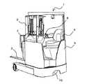
図1は本発明に係る座乗式リーチ型フォークリフトを右前方から見た斜視図である。図1に示すようにこのフォークリフトは、車体1の後方に支持された車体1の前後方向に進退、及び上下方向に伸縮するマスト2と、マスト2に傾動可能に支持されたフォーク3とを備えている。また、車体1の前部には、車体1に対して横向きに座ることができる運転席4が設けられており、この運転席4の下部には、走行装置や操舵装置等を収容するケーシング5が設けられている。さらに、ケーシング5の下方には、フォークリフトの走行と操舵とを担う駆動輪10が配されており、この駆動輪10は360°旋廻することができるようになっている。
【0015】
上記運転席4の右側から車体1の後方側にわたっては、図1及び図2に示すように、運転操作盤7が設けられている。この運転操作盤7には、マスト2の上下方向の伸縮を制御するリフト制御レバー6a、マスト2の前後方向の進退を制御するリーチ制御レバー6b、フォーク3の傾動を制御するチルト制御レバー6c、フォークリフトの走行方向(駆動輪10の回転方向)を制御するディレクショナルスイッチ6d、以下で詳述する制御パネル6e、が配置され、これらの他にも照明灯スイッチ、メインスイッチ、非常停止スイッチなどが配置される。運転操作盤7の右前端部には操舵用のハンドル8が設けられ、さらに、運転席4の床部には図示されていないがブレーキペダル、アクセルペダルが配置されている。なお、本実施の形態では、ハンドル8と駆動輪10との間に機械的な連結構造はなく、いわゆるフライバイワイヤ式ステアリング装置とされている。
【0016】
図3は本発明のステアリング制御装置を含む、このフォークリフトの走行・操舵系の機能ブロック図である。図3に示すように、ハンドル8の操作量(操作角)は、ポテンショメータからなるハンドル回転センサ31にて検出されて、旋廻制御手段32に伝達される。旋廻制御手段32は、ハンドル8の操作角が伝達されると、この操作角に基づいてステアリングモータ11を回転駆動するようになっている。ステアリングモータ11が回転駆動されると操舵歯車16が回転し、この操舵歯車16に噛合う操舵従動歯車15を回転させる。操舵従動歯車15は走行モータ13の回転軸14と同軸上となるよう配されており、操舵従動歯車15が回転すると、走行モータ13と駆動輪10との間に介設された走行用減速機構、及び駆動輪10が旋廻することになる。なお、この際走行モータ13は旋廻せず、そのままの位置で保持される。
【0017】
さらに、操舵従動歯車15には旋廻角検出歯車17が噛合わされており、操舵従動歯車15が回転すると、この旋廻角検出歯車17も回転する。旋廻角検出歯車17はポテンショメータで構成される旋廻角センサ18に連結されているため、旋廻角検出歯車17の回転は旋廻角センサ18により検出され、この検出出力が旋廻制御手段32に伝達されるようになっている。
【0018】
旋廻制御手段32には、操舵モードを設定する操舵モード設定手段33からは設定された操舵モードの情報が伝達され、ハンドル8の操作角と駆動輪10の旋廻角との関係(比率)を設定する比率設定手段34からは設定された比率の情報が伝達されるようになっており、旋廻制御手段32は、設定された操舵モードに従った上で、ハンドル回転センサ31の出力と旋廻角センサ18の出力との関係が設定された比率となるようにステアリングモータ11を駆動する。
【0019】
また、図3に示すように、アクセルペダル9、ディレクショナルスイッチ6dの操作が走行制御手段12に伝達されると、走行制御手段12は走行モータ13を回転駆動させるようになっている。走行モータ13が回転駆動されると、その回転が回転軸14と走行用減速機構を介して駆動輪10に伝わり、駆動輪10が回転することになる。
【0020】
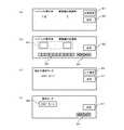
操舵モードの設定は操舵モード設定手段33によって行われ、ハンドル8の操作角と駆動輪10の旋廻角との比率の設定は比率設定手段34によって行われるが、この際に制御パネル6eが活用される。この制御パネル6eは表面がタッチパネルとされたディスプレイ装置であり、操舵モードの設定及び比率の設定時には、例えば図4(a)〜(d)に示す画面が表示されると共に、タッチパネルを操作した信号が操舵モードの設定時には操舵モード設定手段33に伝達され、比率の設定時には比率設定手段34に伝達される。また、操舵モードの設定と比率の設定とを順番に行えるようにするため、操舵モードの設定が終れば比率の設定が可能な状態とされ、比率の設定が終れば操舵モードの設定が可能な状態とされるようになっている。
【0021】
以下、図4ないし図7を参照しながら、操舵モードの設定及び比率の設定の手順につき詳細に説明する。
【0022】
運転者がメインスイッチを操作してフォークリフトの電源を投入すると、比率設定手段34は走行モータ13の回転を検出するロータリーエンコーダで構成される回転センサ19の出力を得て走行モータ13が停止していることを確認する(S501)。
【0023】
走行モータ13が停止していることが確認されると(S501のYES)、次に比率設定手段34は、図4(a)に示すように制御パネル6eに現在のハンドル8の操作角に対する駆動輪10の旋廻角の比率を表示する(S502)。図4(a)では、ハンドル8の操作角と駆動輪10の旋廻角との比率は14対1(ハンドル8が1回転すると、駆動輪10が1/14回転する)となっている。運転者は、ハンドル8の操作角と駆動輪10の旋廻角との比率を変更する場合には、制御パネル6eに表示された比率設定キー61を押下し、変更しない(現状のままで構わない)場合には、決定キー65を押下する。
【0024】
比率設定キー61が押下された場合(S503のYES)、比率設定手段34は、図4(b)に示すように制御パネル6eに入力欄63やテンキー62、カーソルキー64を表示する(S504)。そこで、運転者は表示されたテンキー62やカーソルキー64を用いて入力欄63に、ハンドル8の操作角と駆動輪10の旋廻角との比率を入力する。例えば入力欄63に7:1が入力されると、比率設定手段34は入力された比率を取り込み(S505)、決定キー65が押下されれば(S506のYES)、ハンドル8の操作角と駆動輪10の旋廻角との比率を7:1に設定する(S507)。これ以降、旋廻制御手段32は、旋廻角センサ18から伝達される駆動輪10の旋廻角がハンドル回転センサ31から伝達されるハンドル8の操作角の1/7の角度となるようにステアリングモータ11を回転駆動する。
【0025】
従って、駆動輪10を頻繁に大きく旋廻させるような運転を行う場合、運転者は入力欄63にハンドル8の操作角に対する駆動輪10の旋廻角が大きくなる比率を入力し設定すれば、ハンドル8を少し操作するだけで駆動輪10を大きく旋廻させることができ、フォークリフトの運転を楽に行える。また、駆動輪10の旋廻角の微調整が必要な運転を行う場合、運転者は、入力欄63にハンドル8の操作角に対する駆動輪10の旋廻角が小さくなる比率を入力し設定すれば、微調整を楽に行える。
【0026】
また、例えば駆動輪10の旋廻許容角度が180°に設定される場合には比率を12:1に設定し、駆動輪10の旋廻許容角度が240°に設定される場合には比率を9:1に設定すれば、いずれも駆動輪10の旋廻が許容される範囲をハンドル8での6回転分とすることができ、旋廻許容角度は異なっていても同じような感覚で操作できるようになる。
【0027】
比率設定手段34は比率の設定と同時に、操舵モード設定手段33に対し比率の設定が終了した旨の信号を伝える。すると、操舵モード設定手段33は、図4(c)に示すように制御パネル6eに現在の操舵モードを表示する(S508)。又、比率を変更することなく決定キー65が押下された場合は(S509のYES)、比率設定手段34は現在の比率を保持したままで、操舵モード設定手段33に対し比率の設定が終了した旨の信号を伝える。本実施の形態では、操舵モードには、駆動輪10の旋廻許容角度に制限が無く駆動輪10が360°旋廻することが可能な360°モードと、駆動輪10の旋廻許容角度が180°である180°モードの2種類の操舵モードが採用されている。
【0028】
ここでは、現在360°モードが設定されているとする。従って、図4(c)の制御パネル6eには、現在設定されている操舵モードとして「360°モード」の文字が表示されている。ここで、操舵モードを180°モードに変更する場合、運転者は制御パネル6eに表示されたモード選択キー66を押下し、360°モードのままでよい場合は、制御パネル6eに表示された決定キー67を押下する。
【0029】
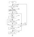
モード選択キー66が押下された場合(S510のYES)、操舵モード設定手段33は、図4(d)に示すように制御パネル6eに操舵モードの表示欄68やカーソルキー64を表示する(S511)。そこで、運転者は表示されたカーソルキー64を用いて表示欄68の操舵モードの表示を切り替える。例えばカーソルキー64を押下して表示欄68に「180°モード」が表示されるようにしたり、「360°モード」が表示されるようにしたりする。表示欄68に「360°モード」が表示されている状態で(S512のYES)、決定キー65が押下されれば(S513のYES)、操舵モード設定手段33は旋廻許容角度の制限を解除して操舵モードを360°モードに設定する(S514)。これ以降、旋廻制御手段32は、360°モードでステアリングモータ11を制御することになり、駆動輪10を無制限に旋廻させることができるようになる。
【0030】
一方、表示欄68に「180°モード」が表示されている状態で(S512のNO)、決定キー65が押下されれば(S515のYES)、操作モード設定手段33は旋廻許容角度を180°に制限して操舵モードを180°モードに設定する(S516)。180°モードが設定されると、操舵モード設定手段33は、旋廻角センサ18からの出力に基づいて、現在の駆動輪10の旋廻角θを検出する(S517)。駆動輪10の旋廻角θとは、図7に示すようにフォークリフトの車体前方向に対する走行モータ13が正回転したときの駆動輪10の進行方向Bの角度のことであり、ここでは左回りに正としている
。
【0031】
操舵モード制御手段33は、検出した旋廻角θが90°〜270°の範囲内であるか否かを判定し(S518)、90°〜270°の範囲内でなければ、駆動輪10の旋廻許容範囲を0°〜90°及び270°〜360°、つまりフォークリフトの車体前方向から左右に90°ずつと設定する(S519)。また、検出した旋廻角θが90°〜270°であれば、操舵モード制御手段33は、駆動輪10の旋廻許容範囲を90°〜270°、つまりフォークリフトの車体後方向から左右に90°ずつと設定し(S520)、更に走行モータ13の極性を反転させる指示を走行制御装置12に与える(S521)。
【0032】
このようにして180°モードが設定された後、旋廻制御手段32は、下記のようにしてステアリングモータ11を制御する。
【0033】
例えば、駆動輪10の旋廻許容範囲が車体前方向から左右に90°ずつと設定されている場合、旋廻制御手段32は、旋廻角センサ18から得られる現在の駆動輪10の旋廻角が車体前方向から左に90°であるときに、ハンドル回転センサ31から伝達されるハンドル8の操作角が駆動輪10の旋廻角を大きくする角度であれば、その操作角の大小に拘わらずステアリングモータ11を駆動しない。また、旋廻制御手段32は、旋廻角センサ18から得られる現在の駆動輪10の旋廻角が車体前方向から右に90°、つまり車体前方向から左に270°であるときに、ハンドル回転センサ31から伝達されるハンドル8の操作角が駆動輪10の旋廻角を小さくする角度であれば、その操作角の大小に拘わらずステアリングモータ11を駆動しない。つまり、駆動輪10の旋廻角が旋廻許容範囲を超えるようにハンドル8を操作しても、ハンドル8が空転するだけで駆動輪10は旋廻しないことになる。駆動輪10の旋廻角が車体前方向から左に90°及び270°以外の場合、駆動輪10の旋廻角が車体前方向から左に90°又は270°であっても旋廻角が旋廻許容範囲の内側へ向うハンドル8を操作である場合には、旋廻制御手段32は、比率設定手段34によって予め設定されたハンドル8の操作角と駆動輪10の旋廻角との比率に従って、ステアリングモータ11を駆動する。
【0034】
このようにして、駆動輪が360°旋廻可能に設けられたフォークリフトでありながら、駆動輪10の旋廻許容範囲が車体前方向から左右に90°ずつとされ、運転者は、機械的なストッパにより駆動輪の旋廻許容範囲が制限されたフォークリフトを運転する場合と同様の感覚で、運転することができるようになる。
【0035】
以上、本発明を座乗式リーチ型フォークリフトに適用した場合について述べたが、本発明はこれ以外のタイプの、駆動輪が360°旋廻可能とされたフォークリフトにも適用可能である。
【0036】
【発明の効果】
本発明によれば、運転者は、自分が運転しやすい操舵モードを選択し設定した上で、ハンドル操作をして駆動輪を旋廻させることができ、また、ハンドルの操作角と駆動輪の旋廻角との関係を自分が運転しやすいものに変更することができるので、フォークリフトを思い通りに運転することができ、その結果としてフォークリフトを用いた作業を効率よく行うことができる。
【図面の簡単な説明】
【図1】駆動輪が360°旋廻可能に設けられたフォークリフトの全体斜視図。
【図2】フォークリフトの運転操作盤付近を示す斜視図。
【図3】本発明のステアリング制御装置の機能ブロック図。
【図4】制御パネルの概念図であり、(a)は比率設定の初期画面、(b)は比率入力画面、(c)は操舵モード設定の初期画面、(d)は操舵モード選択画面を示す。
【図5】ハンドルの操作量と駆動輪の旋廻角との比率の設定手順を示すフローチャート。
【図6】操舵モードの設定手順を示すフローチャート。
【図7】駆動輪の旋廻角を示す説明図。
【符号の説明】
6e 制御パネル
8 ハンドル
10 駆動輪
11 ステアリングモータ
13 走行モータ
18 旋廻角センサ
19 回転センサ
31 ハンドル回転センサ
32 旋廻制御手段
33 操舵モード設定手段
34 比率設定手段[0001]
TECHNICAL FIELD OF THE INVENTION
The present invention relates to a steering control device for a forklift in which drive wheels are provided so as to be able to rotate 360 °.
[0002]
[Prior art]
Conventionally, a seat-type reach-type forklift as shown in FIG. 1 has been used. A driver sits on a
[0003]
By the way, in such a seat-type reach-type forklift, the turning angle of the
[0004]
[Problems to be solved by the invention]
However, the operation of a forklift in which the
[0005]
Accordingly, an object of the present invention is to provide a steering control device of a forklift capable of turning a drive wheel through 360 °, in which a driver can select and operate a steering characteristic according to his / her preference.
[0006]
[Means to solve the problem]
In order to achieve the above object, a steering control device for a forklift according to the present invention is a steering control device for a forklift that rotates a drive wheel, which is provided on a vehicle body so as to be able to rotate through 360 °, in accordance with a steering operation. An operation amount detection means for detecting an operation amount, a rotation angle detection means for detecting a rotation angle of the drive wheel, a limited steering mode in which the rotation allowable angle of the drive wheel is a predetermined value less than 360 °, and a rotation permission of the drive wheel. A steering mode setting means for selecting and setting one of a plurality of steering modes including an unrestricted steering mode in which the angle is not limited, and driving based on an operation amount of a steering wheel according to a steering mode set by the steering mode setting means. Turning control means for controlling the turning of the wheels, the turning control means turning the driving wheels within a range in which the turning angles of the driving wheels do not exceed the allowable turning angles. I am going to make it.
[0007]
Here, the limited steering mode in which the turning angle of the driving wheel is a predetermined value of less than 360 ° is, for example, a turning angle of the driving wheel of 180 ° and a range of 90 ° left and right with respect to the front direction of the vehicle body. The limited steering mode in which the turning of the drive wheel is allowed or the limited steering mode in which the turning of the drive wheel is allowed in a range of 120 ° to the left and right with respect to the forward direction of the vehicle at a drive allowable rotation angle of 240 °. it can.
[0008]
Therefore, according to the present invention, the turning control means controls the turning of the drive wheels in accordance with the set steering mode, so that the driver can operate the steering wheel after selecting his / her favorite steering mode. For example, if the steering mode is set to the unrestricted steering mode in which the turning angle of the driving wheel is not limited, the driver can turn the driving wheel 360 ° by operating the steering wheel, and the forklift can be advanced only by operating the steering wheel. The direction can be changed freely. Further, if the steering mode is set to the limited steering mode in which the turning allowable angle of the drive wheel is a predetermined value of less than 360 °, the turning control means controls the turning angle of the driving wheel so as not to exceed the turning allowable angle. The driver can operate a forklift in which the drive wheels can rotate through 360 ° in the same sense as when driving a forklift in which the range in which the drive wheels are allowed to rotate is limited by a mechanical stopper. Become.
[0009]
By the way, the present invention includes ratio setting means for setting a relationship between the operation amount of the steering wheel and the turning angle of the driving wheel, and the turning control means includes a steering operation amount and a turning angle of the driving wheel set by the ratio setting means. According to the relationship, the turning of the drive wheels can be controlled based on the operation amount of the steering wheel. Here, the relationship between the operation amount of the steering wheel and the turning angle of the drive wheel is, for example, at what ratio the drive wheel rotates with respect to the operation amount of the steering wheel. More specifically, the ratio when the drive wheel rotates 180 ° by rotating the handle one rotation (360 ° rotation) is 2: 1.
[0010]
This allows the driver to set the ratio of the turning angle of the drive wheel to the amount of operation of the steering wheel to be large when the driver sets the ratio of the turning angle of the driving wheel to the operation amount of the steering wheel to increase the drive wheel by operating the steering wheel a little. The forklift can be turned easily and can be operated easily. For example, if the ratio is changed from 2: 1 to 1: 2, the drive wheel rotates by 180 ° when the handle is rotated once (360 °), so that the drive wheel rotates by 720 °. Can be changed. In addition, when performing a driving that requires fine adjustment of the turning angle of the driving wheel, the driver can easily perform the fine adjustment by setting a small ratio of the turning angle of the driving wheel to the operating angle of the steering wheel. For example, if the ratio is changed from 2: 1 to 4: 1, the drive wheel is turned by 180 ° when the steering wheel is turned once (360 °), so that the drive wheel turns by 90 °. Can be changed.
[0011]
Further, for example, when the rotation allowable angle of the driving wheel is set to 180 °, the ratio is set to 12: 1, and when the rotation allowable angle of the driving wheel is set to 240 °, the ratio is set to 9: 1. If set, the range in which the turning of the drive wheel is allowed can be set to six rotations (2160 °) with the handle, and the operation can be performed with the same feeling even if the turning allowable angle is different.
[0012]
Further, the present invention further comprises a rotation detecting means for detecting the rotation of the driving wheel, and only when the rotation of the driving wheel is stopped, the setting of the steering mode or the relationship between the operation amount of the steering wheel and the turning angle of the driving wheel. Can be set.
[0013]
As a result, it is possible to prevent the steering mode from being changed by mistake and the relationship between the operation amount of the steering wheel and the turning angle of the drive wheel to be changed while the drive wheel is rotating and the forklift is running. Safety can be ensured.
[0014]
BEST MODE FOR CARRYING OUT THE INVENTION
FIG. 1 is a perspective view of a seat-type reach-type forklift according to the present invention as viewed from the right front. As shown in FIG. 1, the forklift includes a
[0015]
A driving
[0016]
FIG. 3 is a functional block diagram of a traveling / steering system of the forklift including the steering control device of the present invention. As shown in FIG. 3, the operation amount (operation angle) of the handle 8 is detected by a
[0017]
Further, a turning angle detecting gear 17 is meshed with the steering driven
[0018]
Information about the set steering mode is transmitted to the turning control means 32 from the steering mode setting means 33 for setting the steering mode, and the relationship (ratio) between the operation angle of the steering wheel 8 and the turning angle of the
[0019]
Further, as shown in FIG. 3, when the operations of the
[0020]
The setting of the steering mode is performed by the steering mode setting means 33, and the setting of the ratio between the operation angle of the steering wheel 8 and the turning angle of the
[0021]
Hereinafter, the procedure of setting the steering mode and setting the ratio will be described in detail with reference to FIGS.
[0022]
When the driver turns on the power of the forklift by operating the main switch, the ratio setting means 34 obtains the output of the
[0023]
When it is confirmed that the traveling
[0024]
When the
[0025]
Therefore, in the case of performing a driving operation in which the
[0026]
Further, for example, when the rotation allowable angle of the
[0027]
The ratio setting means 34 transmits a signal to the steering mode setting means 33 to the effect that the ratio setting has been completed, simultaneously with the setting of the ratio. Then, the steering mode setting means 33 displays the current steering mode on the
[0028]
Here, it is assumed that the 360 ° mode is currently set. Therefore, on the
[0029]
When the mode selection key 66 is pressed (YES in S510), the steering mode setting means 33 displays a steering
[0030]
On the other hand, in a state where “180 ° mode” is displayed in the display field 68 (NO in S512), if the
[0031]
The steering mode control means 33 determines whether or not the detected turning angle θ is in the range of 90 ° to 270 ° (S518), and if not, the turning of the
[0032]
After the 180 ° mode is thus set, the turning control means 32 controls the steering motor 11 as described below.
[0033]
For example, when the turning allowable range of the
[0034]
In this way, while the drive wheel is a forklift provided to be able to rotate 360 °, the allowable rotation range of the
[0035]
As described above, the case where the present invention is applied to the sitting-type reach-type forklift is described. However, the present invention is also applicable to other types of forklifts in which the drive wheels can be rotated by 360 °.
[0036]
【The invention's effect】
According to the present invention, the driver can select and set a steering mode in which he or she can easily drive, and then operate the steering wheel to rotate the drive wheel. Since the relationship with the corner can be changed to one that is easy for the driver to drive, the forklift can be driven as desired, and as a result, work using the forklift can be performed efficiently.
[Brief description of the drawings]
FIG. 1 is an overall perspective view of a forklift in which drive wheels are provided to be able to rotate 360 °.
FIG. 2 is a perspective view showing the vicinity of a driving operation panel of the forklift.
FIG. 3 is a functional block diagram of a steering control device according to the present invention.
4A and 4B are conceptual diagrams of a control panel. FIG. 4A shows an initial screen for setting a ratio, FIG. 4B shows an initial screen for setting a steering ratio, FIG. 4C shows an initial screen for setting a steering mode, and FIG. Show.
FIG. 5 is a flowchart showing a setting procedure of a ratio between a steering wheel operation amount and a turning angle of a drive wheel.
FIG. 6 is a flowchart showing a setting procedure of a steering mode.
FIG. 7 is an explanatory diagram showing a turning angle of a drive wheel.
[Explanation of symbols]
6e Control panel 8
Claims (4)
Translated fromJapaneseハンドルの操作量を検出する操作量検出手段と、
駆動輪の旋廻角を検出する旋廻角検出手段と、
駆動輪の旋廻許容角度が360°未満の所定値である制限操舵モードと、駆動輪の旋廻許容角度が制限されない無制限操舵モードとを含む複数の操舵モードのうち一つを選択して設定する操舵モード設定手段と、
操舵モード設定手段により設定された操舵モードに従い、ハンドルの操作量に基づいて駆動輪の旋廻を制御する旋廻制御手段と、を備え、
旋廻制御手段が、駆動輪の旋廻角が旋廻許容角度を超えない範囲で駆動輪を旋廻させることを特徴とするフォークリフトのステアリング制御装置。A steering control device of a forklift for rotating a drive wheel, which is provided on a vehicle body so as to be rotatable through 360 °, in accordance with a steering wheel operation,
Operation amount detection means for detecting an operation amount of the steering wheel;
Turning angle detecting means for detecting the turning angle of the drive wheel;
Steering that selects and sets one of a plurality of steering modes including a limited steering mode in which the rotation allowable angle of the drive wheel is a predetermined value less than 360 ° and an unlimited steering mode in which the rotation allowable angle of the drive wheel is not limited. Mode setting means;
Turning control means for controlling the turning of the drive wheels based on the operation amount of the steering wheel according to the steering mode set by the steering mode setting means,
A turning control means for turning a drive wheel within a range in which the turning angle of the driving wheel does not exceed an allowable turning angle.
前記旋廻制御手段が、比率設定手段により設定されたハンドルの操作量と駆動輪の旋廻角との関係に従い、ハンドルの操作量に基づいて駆動輪の旋廻を制御することを特徴とする請求項1又は請求項2に記載のフォークリフトのステアリング制御装置。A ratio setting means for setting a relationship between the operation amount of the steering wheel and the turning angle of the drive wheel,
2. The method according to claim 1, wherein the rotation control means controls the rotation of the drive wheel based on the operation amount of the steering wheel in accordance with a relationship between the operation amount of the steering wheel and the rotation angle of the drive wheel set by the ratio setting means. A steering control device for a forklift according to claim 2.
Priority Applications (1)
| Application Number | Priority Date | Filing Date | Title |
|---|---|---|---|
| JP2002253841AJP3966789B2 (en) | 2002-08-30 | 2002-08-30 | Forklift steering control device |
Applications Claiming Priority (1)
| Application Number | Priority Date | Filing Date | Title |
|---|---|---|---|
| JP2002253841AJP3966789B2 (en) | 2002-08-30 | 2002-08-30 | Forklift steering control device |
Publications (2)
| Publication Number | Publication Date |
|---|---|
| JP2004090758Atrue JP2004090758A (en) | 2004-03-25 |
| JP3966789B2 JP3966789B2 (en) | 2007-08-29 |
Family
ID=32059735
Family Applications (1)
| Application Number | Title | Priority Date | Filing Date |
|---|---|---|---|
| JP2002253841AExpired - Fee RelatedJP3966789B2 (en) | 2002-08-30 | 2002-08-30 | Forklift steering control device |
Country Status (1)
| Country | Link |
|---|---|
| JP (1) | JP3966789B2 (en) |
Cited By (6)
| Publication number | Priority date | Publication date | Assignee | Title |
|---|---|---|---|---|
| WO2009099806A1 (en)* | 2008-02-05 | 2009-08-13 | Crown Equipment Corporation | A materials handling vehicle with a module capable of changing a steerable wheel to control handle position ratio |
| JP2010023591A (en)* | 2008-07-16 | 2010-02-04 | Nippon Yusoki Co Ltd | Steering and running device |
| KR100970422B1 (en) | 2008-07-31 | 2010-07-15 | 그린모텍(주) | Travel steering for electric forklift |
| CN101948088A (en)* | 2009-07-09 | 2011-01-19 | 林德材料控股有限责任公司 | The handling device of floor conveying equipment |
| EP2168905B1 (en)* | 2008-09-26 | 2015-12-16 | STILL GmbH | Industrial truck with display and operating device |
| KR20230091337A (en)* | 2021-12-16 | 2023-06-23 | (주)시스콘 | Forklift equipped with multi-action conversion module |
- 2002
- 2002-08-30JPJP2002253841Apatent/JP3966789B2/ennot_activeExpired - Fee Related
Cited By (15)
| Publication number | Priority date | Publication date | Assignee | Title |
|---|---|---|---|---|
| US8172033B2 (en) | 2008-02-05 | 2012-05-08 | Crown Equipment Corporation | Materials handling vehicle with a module capable of changing a steerable wheel to control handle position ratio |
| US8412431B2 (en) | 2008-02-05 | 2013-04-02 | Crown Equipment Corporation | Materials handling vehicle having a control apparatus for determining an acceleration value |
| US9421963B2 (en) | 2008-02-05 | 2016-08-23 | Crown Equipment Corporation | Materials handling vehicle having a control apparatus for determining an acceleration value |
| CN101939247A (en)* | 2008-02-05 | 2011-01-05 | 克朗设备公司 | A materials handling vehicle with a module capable of changing a steerable wheel to control handle position ratio |
| US8718890B2 (en) | 2008-02-05 | 2014-05-06 | Crown Equipment Corporation | Materials handling vehicle having a control apparatus for determining an acceleration value |
| US7980352B2 (en) | 2008-02-05 | 2011-07-19 | Crown Equipment Corporation | Materials handling vehicle having a steer system including a tactile feedback device |
| WO2009099806A1 (en)* | 2008-02-05 | 2009-08-13 | Crown Equipment Corporation | A materials handling vehicle with a module capable of changing a steerable wheel to control handle position ratio |
| AU2009210522B2 (en)* | 2008-02-05 | 2015-05-14 | Crown Equipment Corporation | A materials handling vehicle with a module capable of changing a steerable wheel to control handle position ratio |
| JP2010023591A (en)* | 2008-07-16 | 2010-02-04 | Nippon Yusoki Co Ltd | Steering and running device |
| KR100970422B1 (en) | 2008-07-31 | 2010-07-15 | 그린모텍(주) | Travel steering for electric forklift |
| EP2168905B1 (en)* | 2008-09-26 | 2015-12-16 | STILL GmbH | Industrial truck with display and operating device |
| CN101948088B (en)* | 2009-07-09 | 2015-04-08 | 林德材料处理有限责任公司 | Operating means for ground conveying equipment |
| CN101948088A (en)* | 2009-07-09 | 2011-01-19 | 林德材料控股有限责任公司 | The handling device of floor conveying equipment |
| KR20230091337A (en)* | 2021-12-16 | 2023-06-23 | (주)시스콘 | Forklift equipped with multi-action conversion module |
| KR102670523B1 (en) | 2021-12-16 | 2024-05-30 | (주)시스콘로보틱스 | Forklift equipped with multi-action conversion module |
Also Published As
| Publication number | Publication date |
|---|---|
| JP3966789B2 (en) | 2007-08-29 |
Similar Documents
| Publication | Publication Date | Title |
|---|---|---|
| US20210197892A1 (en) | Rotation control system for a steering wheel and method | |
| US9663211B2 (en) | Boat maneuvering system | |
| US20200033876A1 (en) | Steering system for autonomous vehicle | |
| WO2010043944A1 (en) | Parking assistance apparatus and control method thereof | |
| JP4925701B2 (en) | Ship | |
| JP5916520B2 (en) | Inverted pendulum type vehicle | |
| US20160090165A1 (en) | Marine propulsion device | |
| JP2010247760A (en) | Vehicle | |
| JP2020049960A (en) | Tilt trim system for outboard engine | |
| JP2008213769A (en) | Vehicle operating device | |
| CN109311394A (en) | Steering wheel with operating elements and method for setting functions for a vehicle | |
| JP3966789B2 (en) | Forklift steering control device | |
| US11414832B2 (en) | Work vehicle | |
| CN105408179A (en) | Travel assistance system and travel assistance method with travel adjustment | |
| JP2007145207A (en) | Vehicle steering control device | |
| CN220165734U (en) | Walking type omnidirectional forklift | |
| JP2016159782A (en) | Steering device | |
| JP2022128488A (en) | travel control device | |
| JP2022128488A5 (en) | ||
| JP2023049540A (en) | Steering wheel position adjustment device | |
| JP3894538B2 (en) | Control device for omnidirectional forklift | |
| JP2003306160A (en) | Cargo handling vehicle | |
| JP2004075217A (en) | Forklift | |
| JP2006182084A (en) | vehicle | |
| JP6812868B2 (en) | Industrial vehicle |
Legal Events
| Date | Code | Title | Description |
|---|---|---|---|
| A621 | Written request for application examination | Free format text:JAPANESE INTERMEDIATE CODE: A621 Effective date:20041026 | |
| A977 | Report on retrieval | Free format text:JAPANESE INTERMEDIATE CODE: A971007 Effective date:20070315 | |
| A131 | Notification of reasons for refusal | Free format text:JAPANESE INTERMEDIATE CODE: A131 Effective date:20070322 | |
| A521 | Written amendment | Free format text:JAPANESE INTERMEDIATE CODE: A523 Effective date:20070515 | |
| TRDD | Decision of grant or rejection written | ||
| A01 | Written decision to grant a patent or to grant a registration (utility model) | Free format text:JAPANESE INTERMEDIATE CODE: A01 Effective date:20070529 | |
| A61 | First payment of annual fees (during grant procedure) | Free format text:JAPANESE INTERMEDIATE CODE: A61 Effective date:20070529 | |
| R150 | Certificate of patent or registration of utility model | Free format text:JAPANESE INTERMEDIATE CODE: R150 Ref document number:3966789 Country of ref document:JP Free format text:JAPANESE INTERMEDIATE CODE: R150 | |
| FPAY | Renewal fee payment (event date is renewal date of database) | Free format text:PAYMENT UNTIL: 20100608 Year of fee payment:3 | |
| FPAY | Renewal fee payment (event date is renewal date of database) | Free format text:PAYMENT UNTIL: 20110608 Year of fee payment:4 | |
| R250 | Receipt of annual fees | Free format text:JAPANESE INTERMEDIATE CODE: R250 | |
| FPAY | Renewal fee payment (event date is renewal date of database) | Free format text:PAYMENT UNTIL: 20110608 Year of fee payment:4 | |
| FPAY | Renewal fee payment (event date is renewal date of database) | Free format text:PAYMENT UNTIL: 20120608 Year of fee payment:5 | |
| R250 | Receipt of annual fees | Free format text:JAPANESE INTERMEDIATE CODE: R250 | |
| FPAY | Renewal fee payment (event date is renewal date of database) | Free format text:PAYMENT UNTIL: 20120608 Year of fee payment:5 | |
| FPAY | Renewal fee payment (event date is renewal date of database) | Free format text:PAYMENT UNTIL: 20130608 Year of fee payment:6 | |
| R250 | Receipt of annual fees | Free format text:JAPANESE INTERMEDIATE CODE: R250 | |
| S533 | Written request for registration of change of name | Free format text:JAPANESE INTERMEDIATE CODE: R313533 | |
| R350 | Written notification of registration of transfer | Free format text:JAPANESE INTERMEDIATE CODE: R350 | |
| LAPS | Cancellation because of no payment of annual fees |