JP2004087411A - Lamp - Google Patents
LampDownload PDFInfo
- Publication number
- JP2004087411A JP2004087411AJP2002249953AJP2002249953AJP2004087411AJP 2004087411 AJP2004087411 AJP 2004087411AJP 2002249953 AJP2002249953 AJP 2002249953AJP 2002249953 AJP2002249953 AJP 2002249953AJP 2004087411 AJP2004087411 AJP 2004087411A
- Authority
- JP
- Japan
- Prior art keywords
- light
- lamp
- reflector
- light source
- led
- Prior art date
- Legal status (The legal status is an assumption and is not a legal conclusion. Google has not performed a legal analysis and makes no representation as to the accuracy of the status listed.)
- Granted
Links
Images


Landscapes
- Non-Portable Lighting Devices Or Systems Thereof (AREA)
- Led Device Packages (AREA)
Abstract
Translated fromJapaneseDescription
Translated fromJapanese【0001】
【発明の属する技術分野】
本発明は、少なくとも二次元方向に光を放射する光源を用いて、薄型・高効率で見栄えの自由度が高く円形以外の楕円形等の異形状にも対応することができる灯具に関するものである。
【0002】
なお、本明細書中においては、LEDチップそのものは「発光素子」と呼び、LEDチップを搭載したパッケージ樹脂またはレンズ系等の光学装置を含む全体を「発光ダイオード」または「LED」と呼ぶこととする。
【0003】
【従来の技術】
従来のフレネルレンズ併用方式の灯具について、図12を参照して説明する。図12は従来のフレネルレンズ併用方式の灯具の構造を示す断面図である。
この灯具70は、凸レンズ形のLED71、フレネルレンズ72を備えている。そして、LED71から発せられる光は、凸レンズ形の放射面によってある程度集光されてフレネルレンズ72に至り、フレネルレンズ72で配光制御されて平行光として前方へ放射される。
【0004】
しかしながら、フレネルレンズ72と光源の距離の制約により図に示されるように灯具70として厚いものとなり、また横方向にレンズ制御できない光が放射されるため光利用効率が低い。さらに、LED71から斜め45度方向に放射されてフレネルレンズ72に到達する光は、垂直に放射されて到達する光に比べて√2倍の距離を通過しなければならないため、光強度が1/2になって中心部に比較して外周部が暗くなる。
【0005】
そこで、かかる問題を解消するために、特開2001−76513号公報に記載の発明がなされている。図13に示されるように、この公報に記載の車両用灯具74においては、LED75に対向する前面レンズ77の部分に放物反射面78を設けてLED75から放射された光を横方向に反射し、この光をさらに前方に反射する第2反射面79を前面レンズ77に設けている。これによって、灯具として薄いものができる。
【0006】
【発明が解決しようとする課題】
しかしながら、この公報記載の車両用灯具においても、横方向、即ち、二次元方向にレンズ制御できない光が放射されるため光利用効率が低いという問題は解消されておらず、さらに大口径の灯具とした場合に中心部分と周辺部分でLEDからの距離が異なるため輝度のアンバランスが生じるという問題も解決されておらず、さらに部品点数が多く調整が困難であるという問題点があった。
【0007】
そこで、本発明は、薄型で高効率で見栄えの自由度が大きく、灯具全体の輝度が均一でキラキラ光る自然なイメージにできる灯具の提供を課題とするものである。
【0008】
【課題を解決するための手段】
請求項1の発明にかかる灯具は、少なくとも二次元方向へ光を放射する放射光源と、前記放射光源の周囲の一部または全周囲に配置された複数セグメントからなるリフレクタとを備え、前記リフレクタは集光度の異なるセグメントからなるものである。
【0009】
このように、放射光源とその周囲に設けられたリフレクタという構成によって、厚さを極めて薄く、また放射面を大きくすることができる。また、リフレクタは集光度の異なる複数のセグメントで構成されているため、光源からの距離に応じて集光度を調節することによって、全面が均一に光るキラキラ感の得られる灯具とすることもでき、また例えば中心部分を暗く、周辺部分を明るく光らせることもでき、見栄えの自由度を大きくできる。さらに、楕円形状等のリフレクタのセグメントと光源との距離が場所によって異なる形状の灯具においても、光源から離れたセグメントは集光度を大きくし、光源に近いセグメントは集光度を小さくすることによって、全体を均一に光らせることができる。
【0010】
このようにして、薄型で高効率で見栄えの自由度が大きく、楕円形状等の異形状にも効率を低下させることなく対応することができる灯具となる。
【0011】
ここで、少なくとも二次元方向へ光を放射する放射光源とは、二次元方向のみに光を放射する光源のみを意味するものではなく、三次元方向へ光を放射するものであっても、二次元方向へ光を放射するものであることに違いがないから、少なくとも二次元方向へ光を放射するものとして特定したものである。
また、集光度の異なるセグメントとは、放射方向に切断した反射面を含む断面形状を変化させること、屈折率を変化させること等の対応が可能である。
【0012】
請求項2の発明にかかる灯具は、請求項1の構成において、前記リフレクタのセグメントは前記放射光源からの照射密度に応じた集光度を有するものである。
【0013】
これによって、放射光源からの照射密度が高い近い部分のセグメントは集光度を低めに、照射密度が低い遠い部分のセグメントは集光度を高めに設定することによって、リフレクタ全体の輝度のバランスがとれて均一な光り方の灯具とすることができる。また、楕円形等の灯具においても、このようにすることによって全体を均一に光らせることができる。
【0014】
このようにして、薄型で高効率で見栄えの自由度が大きく、楕円形状等の異形状にも効率を低下させることなく対応することができる灯具となる。
【0015】
請求項3の発明にかかる灯具は、請求項1または請求項2の構成において、前記放射光源は発光素子の発光面に対向した二次元方向へ反射する光学面を有するものである。
【0016】
これによって、発光素子の発光面に対向した光学面によって光を二次元方向へ反射できるので、厚さが薄く、1つの発光ダイオードで発光素子の周囲360度にわたって光を放射できる放射光源となる。したがって、リフレクタの各セグメントの集光度を調整することによって、見栄えが良く全体が均一な輝度で自然な発光を実現できる灯具となる。また、大出力が必要になったときにも、大出力の発光素子を1つ用いるのみで目的が達成できる灯具となる。
【0017】
このようにして、薄型で高効率で見栄えの自由度が大きく、楕円形状等の異形状にも効率を低下させることなく対応することができる灯具となる。
【0018】
請求項4の発明にかかる灯具は、請求項3の構成において、前記光学面は、前記発光素子を封止する透明光学材料によって形成されているものである。
【0019】
したがって、光を二次元方向へ反射する反射鏡としての光学面の位置及び形状を封止時に厳密に設定できるので、光学系の位置の設定が容易になる。
【0020】
このようにして、発光素子と二次元方向へ放射するための反射鏡との位置合わせに手間がかかることはなく、容易に高い位置精度を実現することができる。
【0021】
請求項5の発明にかかる灯具は、請求項1乃至請求項4の構成において、前記リフレクタのセグメントは前記放射光源からの距離が最長なものが最短なものの2倍以上であるものである。
【0022】
これによって、放射光の明るさは距離の自乗に反比例するので、光源からの距離が最長なセグメントの集光度を上げて灯具全体の輝度を均一にすることもでき、また灯具の放射面の場所によって輝度を変化させることもできる。このように、光源からの距離の異なるセグメントの集光度を調節することによって、灯具の光り方の見栄えを様々に調節することができる。
【0023】
このようにして、薄型で高効率で見栄えの自由度が大きく、楕円形状等の異形状にも効率を低下させることなく対応することができる灯具となる。
【0024】
【発明の実施の形態】
以下、本発明の実施の形態について図面を参照して説明する。
【0025】
実施の形態1
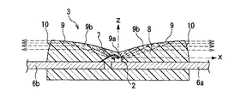
まず、本発明の灯具の実施の形態1について、図1乃至図5を参照して説明する。図1(a)は本発明の実施の形態1にかかる灯具の全体構成を示す平面図、(b)は断面図である。図2は本発明の実施の形態1にかかる灯具の放射光源としてのLEDを示す断面図である。図3(a)は本発明の実施の形態1にかかる灯具のセグメントのA−A断面を示す断面図、(b)はB−B断面を示す断面図である。図4(a)は本発明の実施の形態1の変形例にかかる灯具のセグメントのA−A断面を示す断面図、(b)はB−B断面を示す断面図である。図5(a)は本発明の実施の形態1の別の変形例にかかる灯具のセグメントのA−A断面を示す断面図、(b)はB−B断面を示す断面図である。
【0026】
図1に示されるように、本実施の形態1の灯具1は、中心に発光素子2を内蔵した放射光源としてのLED3が載置され、その周囲に設置された合成樹脂にアルミ蒸着してなるリフレクタ本体4の表面のうち斜線部分が、複数のセグメント5a,5bからなるリフレクタ4a,4bとなっている。図1(b)の断面図に示されるように、リフレクタ4a,4bのセグメント5a,5bは略45度の斜面となっており、LED3の発光素子2の発光面に対向した二次元方向へ反射する光学面9bから二次元方向へ反射されてきた光を上方向(Z軸方向)へ反射する。
【0027】
なお、ここで二次元方向とは、LED3に対する、その周辺に設置されたセグメント5a,5bで構成されたリフレクタ4a,4bの形成する面への方向を意味する。厳密にLED3からZ軸に対して垂直な平面方向ではなく、LED3からの光が、LED3の周囲に設置されたリフレクタ面へ効率良く照射されるものであれば良い。
【0028】
内周のリフレクタ4aはLED3に近接しているので内周のリフレクタ4aのセグメント5aはいずれも平面で、8面のセグメント5aで正八角形を形成している。これに対して、外周のリフレクタ4bのセグメント5bは、図3に示されるようにA−A断面の表面が僅かに凹曲面になっている。
【0029】
次に、LED3の構成について、図2を参照して説明する。ここで、図2に示されるように、発光素子2の中心軸をZ軸とし発光素子2上面をその原点とし、この原点においてX軸とY軸とが直角に交わるように定めてある。
【0030】
図2に示されるように、X−Y平面上に設けられた1対のリード6a,6bのうちリード6aの先端に発光素子2をマウントしている。発光素子2の上面の電極とリード6bの先端とは、ワイヤ7でボンディングされて電気的接続がなされている。これらのリード6a,6bの先端、発光素子2、ワイヤ7が樹脂封止用金型にセットされて、透明エポキシ樹脂8によって図に示すような断面形状に樹脂封止されている。ここで、LED3の上面9の中心部分には微小な平坦面が形成されている。この中心点9aに続いて反射面9bとして発光素子6の発光面の中心を焦点とし、X軸方向を対称軸とする放物線の一部を原点からZ軸に対して60度以上の範囲内においてZ軸の周りに回転させた傘のような形状をしている。また、LED3の側面10は、発光素子2を中心とする球面の一部をなしている。
【0031】
即ち、本実施の形態1の放射光源としてのLED3においては、発光素子2の発光面に対向した二次元方向へ反射する光学面9bを有するものである。
【0032】
かかる構成を有する灯具1の光り方について、図1乃至図3を参照して説明する。
LED3のリード6a,6bに電圧をかけて発光素子2を光らせると、発光素子2から発せられた光のうち、大半の光に相当する、Z軸に対して60度以上の範囲内の光が反射面としての上面9bに至り、これらの光は上面9bへの入射角が臨界角より大きいため全て全反射されて側面10に向かう。ここで、上面9bは発光素子2を焦点としX軸を対称軸とする放物線の一部をZ軸の周りに回転させた形状をしているため、上面9bで反射された光は全てX−Y平面に平行に進み、側面10は発光素子2を中心とする球面の一部をなしているため、光はほぼそのまま平行に進んでZ軸周り360度の方向に面状に放射される。さらに、発光素子2から側面10に直接向かった光は、側面10は発光素子2を中心とする球面の一部をなしているため、屈折することなくそのままの向きで放射される。なお、Z軸方向に放射されたわずかな光は、中心部分に形成された微小な平坦面から、外部放射される。
【0033】
LED3の周囲には略45度の傾斜を有するリフレクタ4aがあるが、上面9bで反射されてX−Y平面に略平行に進んできた光を始めとして、側面10から直接放射された光もX−Y平面に平行に近いため、リフレクタ4aで反射された光はそれぞれがほぼ垂直に近く上方へ進み、少なくともZ軸から20度の範囲内で外部放射される。なお、上記で「平行」と表現している光も、発光素子2の大きさがあるために完全な平行にはならないが、いずれの光もほぼ平行になり、少なくともZ軸から20度の範囲内には確実に入るものとなる。
【0034】
一方、リフレクタ4aの外周のリフレクタ4bによってもLED3から二次元方向に放射された光が反射されるが、上述したようにリフレクタ4bの長手方向は凹曲面になっているため、光が集光されて輝度が高められて上方へ反射される。これによって、光の強さは光源からの距離の自乗に反比例して減衰していくが、光源LED3からの距離が近く減衰率が小さいリフレクタ4aの反射光は、平面のリフレクタ4aによって集光されずに上方へ反射される。これに対して、光源LED3からの距離が遠く減衰率が大きいリフレクタ4bの反射光は、凹曲面のリフレクタ4bによって集光されて上方へ反射される。なお、LED3の中心部分に形成された微小な平坦面から、Z軸方向へ外部放射される光は、LED3の周囲に設置されたリフレクタ4へは至らず、直接外部放射される。
【0035】
発光素子はLEDであり電気エネルギーを直接光エネルギーに変換するため高温にならない。また、発光素子サイズが微小のため光学制御効率を高めることができる。さらに、LED自体に発光素子からの光を二次元方向へ放射するための反射鏡を有し、かつ、この反射鏡が発光素子を透明エポキシ樹脂により封止するとともにモールド形成されているので、従来例のように部品点数が多くなることはなく、発光素子と二次元方向へ放射するための反射鏡との位置合わせに手間がかかることはなく、容易に高い位置精度を実現できる。
【0036】
この結果、上方向(Z軸方向の遠方)より視認した場合、LED3からの直接光及び、集光調整された各リフレクタセグメントからの放射光により、灯具1の全体の輝度が均一でキラキラ光る自然なイメージの灯具とできる。さらに、灯具1は消灯している際にも外部光が反射して全体が均一にキラキラ光る非常に見栄えの良い灯具となる。
【0037】
次に、本実施の形態1の灯具1の変形例について、図1,図4,図5を参照して説明する。図4の変形例は、リフレクタ4bのフラグメント5bのA−A方向には表面が曲率がなく、B−B方向には凹曲率を有しているものである。また、図5の変形例は、両方向に凹曲率を有しているもので、いずれも外側のリフレクタ4bに灯具としてより集光度が必要な場合である。
【0038】
さらに、他の変形例として、内側のセグメント5aは凸面、外側のセグメント5bは平面として内側の反射光を拡散させて全体の輝度を均一とするものとしても良い。この場合本実施の形態1の灯具1よりも広い配光が必要な場合、あるいは光源に対するリフレクタセグメントの立体角が小さい場合に適する。さらに、リフレクタを3つ以上の環状として各セグメントへの光源からの照射密度に応じて曲率を変化させ、集光反射面あるいは拡散反射面とするもの、内側のリフレクタに対して外側のリフレクタのセグメント分割数が大きいもの等、種々の変形例が考えられる。例えば、LED3に近接したリフレクタ4aに対し、外側のリフレクタ4bの輝度の方が高いものとしても良い。
【0039】
このようにして、薄型で高効率で見栄えの自由度が大きく、全体の輝度が均一でキラキラ光る自然なイメージの灯具となる。
【0040】
実施の形態2
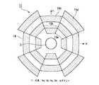
次に、本発明の灯具の実施の形態2について、図6を参照して説明する。図6は本発明の実施の形態2にかかる灯具の全体構成を示す平面図である。
【0041】
図6に示されるように、本実施の形態2の灯具11においては、隣接するリフレクタのセグメントの中央からの距離を異なるものとしてある。即ち、実施の形態1と同様の放射光源としてのLED3を取り囲んで、一番近い位置にセグメント15a、その次に互い違いにセグメント15b、さらに互い違いにセグメント15c、そしてセグメント15dと一段ずつLED3から離れていく。このようにリフレクタのセグメント15a,15b,15c,15dを配置することによって、灯具11の輝点をより分散することができる。そして、各セグメント15a,15b,15c,15dをLED3からの照射密度に応じて曲率を持たせることによって、灯具11全体の輝度を均一にすることができる。
【0042】
なお、隣接するセグメントはこのように完全に互い違いにする必要があるわけではなく、ある程度(例えば、セグメントの幅の半分程度)のずらし量であっても良い。これでも灯具11の輝点をある程度分散することができる。
【0043】
実施の形態3
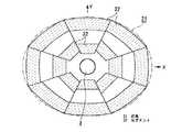
次に、本発明の灯具の実施の形態3について、図7を参照して説明する。図7は本発明の実施の形態3にかかる灯具の全体構成を示す平面図である。
【0044】
図7に示されるように、本実施の形態3の灯具21においては、2段に配列したリフレクタセグメント22によって略楕円形の放射面を形成している。中心には実施の形態1と同様の放射光源としてのLED3を載置し、その周囲には二重にセグメント22を配列して、楕円形状を形成している。そして、各セグメント22をLED3からの照射密度に応じて曲率を持たせることによって、灯具21全体の輝度を均一にすることができる。
【0045】
このようにして、薄型で高効率で見栄えの自由度が大きく、楕円形状等の異形状にも効率を低下させることなく対応することができる灯具となる。
【0046】
実施の形態4
次に、本発明の灯具の実施の形態4について、図8を参照して説明する。図8は本発明の実施の形態4にかかる灯具の全体構成を示す平面図である。
【0047】
図8に示されるように、本実施の形態4の灯具31においては、セグメント32によって楕円形状を形成しているが、放射光源としてのLED3の位置が中央から大きくずれている。これによって、各セグメントの位置も形状も様々となるが、やはりLED3からの照射密度に応じて曲率を持たせることによって、灯具31全体の輝度を均一にすることができる。なお、光源から二次元方向へ均一な放射がなされていれば、各セグメントへの照射密度は各セグメントの光源からの距離の2乗に反比例する。前述の実施の形態でも同様であるが、本実施の形態4では、光源に近接したセグメントと離れたセグメントの距離の比が大きく照射密度の差が大きく生じる。しかし、光源に近接したセグメントを凸面とし、距離が離れるにしたがって曲率を順次小さくし最も離れたセグメントでは平面とすることによって、輝度の均一化を図ることができる。
【0048】
上記各実施の形態においては、セグメントに曲率をもたせることによって灯具全体の輝度を均一にする場合について説明してきたが、必ずしも均一にする場合のみでなく、灯具の輝度を場所によって変えることもできる。要するに、セグメントに曲率をもたせることによって灯具の輝度を制御できるという事実が重要である。
【0049】
実施の形態5
次に、本発明の灯具の実施の形態5について、図9を参照して説明する。図9は本発明の実施の形態5にかかる灯具の全体構成を示す縦断面図である。
【0050】
図9に示されるように、本実施の形態5の灯具41においては、中心のLED43を円盤型の透明体44で囲んでいる。LED43は上記各実施の形態におけるLED3と異なり、垂直方向に設けられた1対のリード46a,46bのうちリード46aの上面に発光素子42をマウントして、発光素子42ともう一方のリード46bとをワイヤで電気的接続をとり、LED3と同様の形状に樹脂封止したものである。上記各実施の形態においても、LED3の代わりにこのLED43を用いることができる。
【0051】
透明体44の下面には、3段階にわたってリフレクタ45が設けられている。これらのリフレクタ45は、LED43から二次元方向に放射されて透明体44の中を透過してきた光を全反射によって上方へ反射する。そして、各段ごとに8つのセグメントに分かれており、放射光源43からの照射密度が高い近い部分のセグメントは集光度を低めに、照射密度が低い遠い部分のセグメントは集光度を高めに設定することによって、リフレクタ全体の輝度のバランスがとれて均一な光り方の灯具とすることができる。
【0052】
実施の形態6
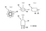
次に、本発明の灯具の実施の形態6について、図10を参照して説明する。図10(a)は本発明の実施の形態6にかかる灯具に用いられる放射光源の全体構成を示す平面図、(b)は放射光源を構成するレンズ型LEDの構成を示す平面図、(c)は側面図、(d)は正面図である。
【0053】
図10(a)に示されるように、本実施の形態6の灯具においては、放射光源として一体型LED3,43の代わりに、レンズ型LED63を8個用いて放射面を二次元方向に向けて八角形に並べた放射光源62を使用している。図10(b),(c),(d)に示されるように、このレンズ型LED63は、封止樹脂レンズ64がβ方向に広く、それと垂直なγ方向に狭くなっている。そして、放射光源62はα−β平面が二次元方向に並ぶように8個のレンズ型LED63を配列している。
【0054】
レンズ型LED63からはβ方向にはやや拡がった放射光がα方向には略平行な放射光が放射されるので、放射光源62は二次元方向に360度隙間なく光を放射する。この放射光源62の周囲に配置される各リフレクタセグメントまでの距離の差が大きい場合は、上記各実施の形態と同様の効果を得ることができる。
【0055】
実施の形態7
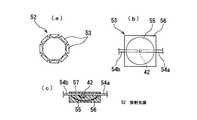
次に、本発明の灯具の実施の形態7について、図11を参照して説明する。図11(a)は本発明の実施の形態7にかかる灯具に用いられる放射光源の全体構成を示す平面図、(b)は放射光源を構成する反射型LEDの構成を示す平面図、(c)は縦断面図である。
【0056】
図11(a)に示されるように、本実施の形態7の灯具においては、放射光源として一体型LED3,43の代わりに、反射型LED53を8個用いて放射面を二次元方向に向けて八角形に並べた放射光源52を使用している。図11(b),(c)に示されるように、この反射型LED53は1対のリード54a,54bのうちリード54aの先端裏側に発光素子42をマウントし、発光素子の上面端子とリード54bとをワイヤで電気的接続をとり、発光素子42の発光面と対向する位置に回転放物面形状の反射鏡55を設置して、全体を透明エポキシ樹脂56で封止したものである。これによって、発光素子42から放射された光は回転放物面形状の反射鏡55で略垂直軸方向に平行に反射されて、放射面57から外部放射される。したがって、反射型構造とすると、発光素子が発する光をより効率良く二次元方向へ放射できる。
【0057】
ここで、発光素子42の光が反射鏡55で正確に垂直軸方向に平行に反射されると、放射光源52の隣り合う反射型LED53の間に光が放射されない部分が生じることになるが、実際には発光素子42の大きさ等の理由で斜め方向に外部放射される光も生じるため、放射光源52は二次元方向に360度隙間なく光を放射する。
【0058】
この放射光源52の周囲に配置される各リフレクタセグメントまでの距離の差が大きい場合は、上記各実施の形態と同様の効果を得ることができる。
【0059】
なお、前述の実施形態のように薄型・小型とはならないが、このような光源でも構わない。
【0060】
上記各実施の形態においては、発光素子として赤色発光素子を用いた場合を想定しているが、何色の発光素子を用いても構わない。また、LEDにおいて発光素子等を封止する光透過性材料として透明エポキシ樹脂を用いているが、透明シリコン樹脂を始めとするその他の材料を用いても良い。
【0061】
灯具のその他の部分の構成、形状、数量、材質、大きさ、接続関係等についても、上記各実施の形態に限定されるものではない。
【0062】
【発明の効果】
以上説明したように、請求項1の発明にかかる灯具は、少なくとも二次元方向へ光を放射する放射光源と、前記放射光源の周囲の一部または全周囲に配置された複数セグメントからなるリフレクタとを備え、前記リフレクタは集光度の異なるセグメントからなるものである。
【0063】
このように、放射光源とその周囲に設けられたリフレクタという構成によって、厚さを極めて薄く、また放射面を大きくすることができる。また、リフレクタは集光度の異なる複数のセグメントで構成されているため、光源からの距離に応じて集光度を調節することによって、全面が均一に光るキラキラ感の得られる灯具とすることもでき、また例えば中心部分を暗く、周辺部分を明るく光らせることもでき、見栄えの自由度を大きくできる。さらに、楕円形状等のリフレクタのセグメントと光源との距離が場所によって異なる形状の灯具においても、光源から離れたセグメントは集光度を大きくし、光源に近いセグメントは集光度を小さくすることによって、全体を均一に光らせることができる。
【0064】
このようにして、薄型で高効率で見栄えの自由度が大きく、楕円形状等の異形状にも効率を低下させることなく対応することができる灯具となる。
【0065】
ここで、少なくとも二次元方向へ光を放射する放射光源とは、二次元方向のみに光を放射する光源のみを意味するものではなく、三次元方向へ光を放射するものであっても、二次元方向へ光を放射するものであることに違いがないから、少なくとも二次元方向へ光を放射するものとして特定したものである。
また、集光度の異なるセグメントとは、放射方向に切断した反射面を含む断面形状を変化させること、屈折率を変化させること等の対応が可能である。
【0066】
請求項2の発明にかかる灯具は、請求項1の構成において、前記リフレクタのセグメントは前記放射光源からの照射密度に応じた集光度を有するものである。
【0067】
これによって、放射光源からの照射密度が高い近い部分のセグメントは集光度を低めに、照射密度が低い遠い部分のセグメントは集光度を高めに設定することによって、リフレクタ全体の輝度のバランスがとれて均一な光り方の灯具とすることができる。また、楕円形等の灯具においても、このようにすることによって全体を均一に光らせることができる。
【0068】
このようにして、薄型で高効率で見栄えの自由度が大きく、楕円形状等の異形状にも効率を低下させることなく対応することができる灯具となる。
【0069】
請求項3の発明にかかる灯具は、請求項1または請求項2の構成において、前記放射光源は発光素子の発光面に対向した二次元方向へ反射する光学面を有するものである。
【0070】
これによって、発光素子の発光面に対向した光学面によって光を二次元方向へ反射できるので、厚さが薄く、1つの発光ダイオードで発光素子の周囲360度にわたって光を放射できる放射光源となる。したがって、リフレクタの各セグメントの集光度を調整することによって、見栄えが良く全体が均一な輝度で自然な発光を実現できる灯具となる。また、大出力が必要になったときにも、大出力の発光素子を1つ用いるのみで目的が達成できる灯具となる。
【0071】
このようにして、薄型で高効率で見栄えの自由度が大きく、楕円形状等の異形状にも効率を低下させることなく対応することができる灯具となる。
【0072】
請求項4の発明にかかる灯具は、請求項3の構成において、前記光学面は、前記発光素子を封止する透明光学材料によって形成されているものである。
【0073】
したがって、光を二次元方向へ反射する反射鏡としての光学面の位置及び形状を封止時に厳密に設定できるので、光学系の位置の設定が容易になる。
【0074】
このようにして、発光素子と二次元方向へ放射するための反射鏡との位置合わせに手間がかかることはなく、容易に高い位置精度を実現することができる。
【0075】
請求項5の発明にかかる灯具は、請求項1乃至請求項4の構成において、前記リフレクタのセグメントは前記放射光源からの距離が最長なものが最短なものの2倍以上であるものである。
【0076】
これによって、放射光の明るさは距離の自乗に反比例するので、光源からの距離が最長なセグメントの集光度を上げて灯具全体の輝度を均一にすることもでき、また灯具の放射面の場所によって輝度を変化させることもできる。このように、光源からの距離の異なるセグメントの集光度を調節することによって、灯具の光り方の見栄えを様々に調節することができる。
【0077】
このようにして、薄型で高効率で見栄えの自由度が大きく、楕円形状等の異形状にも効率を低下させることなく対応することができる灯具となる。
【図面の簡単な説明】
【図1】図1(a)は本発明の実施の形態1にかかる灯具の全体構成を示す平面図、(b)は断面図である。
【図2】図2は本発明の実施の形態1にかかる灯具の放射光源としてのLEDを示す断面図である。
【図3】図3(a)は本発明の実施の形態1にかかる灯具のセグメントのA−A断面を示す断面図、(b)はB−B断面を示す断面図である。
【図4】図4(a)は本発明の実施の形態1の変形例にかかる灯具のセグメントのA−A断面を示す断面図、(b)はB−B断面を示す断面図である。
【図5】図5(a)は本発明の実施の形態1の別の変形例にかかる灯具のセグメントのA−A断面を示す断面図、(b)はB−B断面を示す断面図である。
【図6】図6は本発明の実施の形態2にかかる灯具の全体構成を示す平面図である。
【図7】図7は本発明の実施の形態3にかかる灯具の全体構成を示す平面図である。
【図8】図8は本発明の実施の形態4にかかる灯具の全体構成を示す平面図である。
【図9】図9は本発明の実施の形態5にかかる灯具の全体構成を示す縦断面図である。
【図10】図10(a)は本発明の実施の形態6にかかる灯具に用いられる放射光源の全体構成を示す平面図、(b)は放射光源を構成するレンズ型LEDの構成を示す平面図、(c)は側面図、(d)は正面図である。
【図11】図11(a)は本発明の実施の形態7にかかる灯具に用いられる放射光源の全体構成を示す平面図、(b)は放射光源を構成する反射型LEDの構成を示す平面図、(c)は縦断面図である。
【図12】図12は、従来のフレネルレンズ併用方式の灯具の構造を示す断面図である。
【図13】図13は、従来の灯具の構造を示す断面図である。
【符号の説明】
1,11,21,31,41 灯具
2,42 発光素子
3,43,52,62 放射光源
4a,4b,45 リフレクタ
5a,5b,15a,15b,15c,15d,22,32 セグメント
9b 光学面[0001]
TECHNICAL FIELD OF THE INVENTION
The present invention relates to a lamp capable of coping with irregular shapes such as an elliptical shape other than a circular shape using a light source that emits light in at least a two-dimensional direction, which is thin, highly efficient, has a high degree of freedom of appearance, and is not circular. .
[0002]
In this specification, the LED chip itself is referred to as a “light emitting element”, and the entirety including an optical device such as a package resin or a lens system on which the LED chip is mounted is referred to as a “light emitting diode” or “LED”. I do.
[0003]
[Prior art]
A conventional lamp using a Fresnel lens combined system will be described with reference to FIG. FIG. 12 is a cross-sectional view showing a structure of a conventional lamp using a Fresnel lens.
The
[0004]
However, as shown in the figure, the
[0005]
Then, in order to solve such a problem, the invention described in JP-A-2001-76513 has been made. As shown in FIG. 13, in the
[0006]
[Problems to be solved by the invention]
However, even in the vehicle lamp described in this publication, the problem that the light use efficiency is low because light that cannot be lens-controlled in the horizontal direction, that is, the two-dimensional direction, is not solved. In this case, since the distance from the LED is different between the central part and the peripheral part, the problem that the luminance is unbalanced is not solved, and the number of parts is large and adjustment is difficult.
[0007]
Accordingly, an object of the present invention is to provide a lamp that is thin, highly efficient, has a high degree of freedom in appearance, and has a uniform brightness of the entire lamp and a natural image with glitter.
[0008]
[Means for Solving the Problems]
The lamp according to the first aspect of the present invention includes a radiation light source that emits light in at least a two-dimensional direction, and a reflector including a plurality of segments arranged around a part or the entire periphery of the radiation light source, wherein the reflector is It is composed of segments with different light condensing degrees.
[0009]
As described above, with the configuration of the radiation light source and the reflector provided around the radiation light source, the thickness can be made extremely thin and the radiation surface can be enlarged. In addition, since the reflector is composed of a plurality of segments having different light condensing degrees, by adjusting the light condensing degree in accordance with the distance from the light source, it is also possible to obtain a lamp that can obtain a glittering feeling that the entire surface shines uniformly, Also, for example, the central portion can be made dark and the peripheral portion can be made bright, and the degree of freedom of appearance can be increased. Furthermore, even in a lamp having a shape in which the distance between the reflector segment such as an elliptical shape and the light source differs depending on the location, the segment far from the light source increases the light concentration, and the segment close to the light source decreases the light concentration, so that the overall Can be illuminated uniformly.
[0010]
In this manner, a lamp that is thin, highly efficient, has a large degree of freedom in appearance, and can cope with an irregular shape such as an elliptical shape without lowering the efficiency.
[0011]
Here, a radiation light source that emits light in at least a two-dimensional direction does not only mean a light source that emits light in only a two-dimensional direction, but also a light source that emits light in a three-dimensional direction. Since there is no difference in emitting light in a two-dimensional direction, it is specified that the light is emitted in at least a two-dimensional direction.
In addition, the segments having different light condensing degrees can correspond to changing the cross-sectional shape including the reflecting surface cut in the radial direction, changing the refractive index, and the like.
[0012]
According to a second aspect of the present invention, in the configuration of the first aspect, the reflector segment has a light condensing degree corresponding to an irradiation density from the radiation light source.
[0013]
As a result, the brightness of the entire reflector can be balanced by setting the segments in the near part where the irradiation density from the radiation source is high to a low concentration and the segments in the far parts where the irradiation density is low to a high concentration. It is possible to provide a lamp with a uniform light emission. In addition, even in the case of a lamp having an elliptical shape or the like, it is possible to uniformly illuminate the entire lamp in this manner.
[0014]
In this manner, a lamp that is thin, highly efficient, has a large degree of freedom in appearance, and can cope with an irregular shape such as an elliptical shape without lowering the efficiency.
[0015]
According to a third aspect of the present invention, in the configuration of the first or second aspect, the radiation light source has an optical surface that reflects in a two-dimensional direction and faces a light emitting surface of the light emitting element.
[0016]
Accordingly, the light can be reflected in the two-dimensional direction by the optical surface facing the light emitting surface of the light emitting element, so that the light source has a small thickness and can emit light over 360 degrees around the light emitting element with one light emitting diode. Therefore, by adjusting the light condensing degree of each segment of the reflector, a lamp having a good appearance and capable of realizing natural light emission with uniform luminance as a whole can be obtained. Further, even when a large output is required, the lamp can achieve its purpose only by using one large-output light emitting element.
[0017]
In this manner, a lamp that is thin, highly efficient, has a large degree of freedom in appearance, and can cope with an irregular shape such as an elliptical shape without lowering the efficiency.
[0018]
According to a fourth aspect of the present invention, in the lamp of the third aspect, the optical surface is formed of a transparent optical material for sealing the light emitting element.
[0019]
Therefore, since the position and shape of the optical surface as a reflecting mirror that reflects light in two-dimensional directions can be strictly set at the time of sealing, the position of the optical system can be easily set.
[0020]
In this way, there is no need for troublesome positioning of the light emitting element and the reflecting mirror for emitting light in the two-dimensional direction, and high positional accuracy can be easily realized.
[0021]
According to a fifth aspect of the present invention, in the configuration of the first to fourth aspects of the present invention, the reflector segment whose distance from the radiation light source is the longest is at least twice as long as the shortest one.
[0022]
As a result, since the brightness of the emitted light is inversely proportional to the square of the distance, it is also possible to increase the degree of light collection of the segment having the longest distance from the light source and to make the overall brightness of the lamp uniform, and the location of the radiation surface of the lamp Can change the brightness. As described above, by adjusting the degree of light collection of the segments having different distances from the light source, it is possible to variously adjust the appearance of the lighting of the lamp.
[0023]
In this manner, a lamp that is thin, highly efficient, has a large degree of freedom in appearance, and can cope with an irregular shape such as an elliptical shape without lowering the efficiency.
[0024]
BEST MODE FOR CARRYING OUT THE INVENTION
Hereinafter, embodiments of the present invention will be described with reference to the drawings.
[0025]
First, a first embodiment of a lamp according to the present invention will be described with reference to FIGS. FIG. 1A is a plan view showing the overall configuration of the lamp according to the first embodiment of the present invention, and FIG. 1B is a cross-sectional view. FIG. 2 is a cross-sectional view showing an LED as a radiation light source of the lamp according to the first embodiment of the present invention. FIG. 3A is a sectional view showing an AA section of a segment of the lamp according to the first embodiment of the present invention, and FIG. 3B is a sectional view showing a BB section. FIG. 4A is a sectional view showing an AA section of a segment of a lamp according to a modification of the first embodiment of the present invention, and FIG. 4B is a sectional view showing a BB section. FIG. 5A is a sectional view showing an AA section of a segment of a lamp according to another modification of the first embodiment of the present invention, and FIG. 5B is a sectional view showing a BB section.
[0026]
As shown in FIG. 1, a
[0027]
Here, the two-dimensional direction refers to the direction of the
[0028]
Since the
[0029]
Next, the configuration of the
[0030]
As shown in FIG. 2, the
[0031]
That is, the
[0032]
The lighting of the
When a voltage is applied to the
[0033]
There is a
[0034]
On the other hand, although the light radiated in the two-dimensional direction from the
[0035]
The light-emitting element is an LED, and does not reach a high temperature because it directly converts electric energy into light energy. Further, since the size of the light emitting element is small, the optical control efficiency can be increased. Furthermore, since the LED itself has a reflector for emitting light from the light emitting element in a two-dimensional direction, and this reflector is molded and sealed with a transparent epoxy resin, the conventional As in the example, the number of components does not increase, and there is no trouble in aligning the light emitting element with the reflecting mirror for emitting light in the two-dimensional direction, and high positional accuracy can be easily realized.
[0036]
As a result, when viewed from above (distant in the Z-axis direction), the direct light from the
[0037]
Next, a modified example of the
[0038]
Further, as another modified example, the
[0039]
In this way, a thin, high-efficiency lamp with a large degree of freedom of appearance, a uniform overall brightness and a glittering natural image can be obtained.
[0040]
Next, a second embodiment of the lamp of the present invention will be described with reference to FIG. FIG. 6 is a plan view showing the overall configuration of the lamp according to the second embodiment of the present invention.
[0041]
As shown in FIG. 6, in the
[0042]
Note that the adjacent segments do not need to be completely staggered in this way, and may be shifted to some extent (for example, about half the width of the segment). Even with this, the luminescent spots of the
[0043]
Next, a third embodiment of the lamp of the present invention will be described with reference to FIG. FIG. 7 is a plan view showing the overall configuration of the lamp according to the third embodiment of the present invention.
[0044]
As shown in FIG. 7, in the
[0045]
In this manner, a lamp that is thin, highly efficient, has a large degree of freedom in appearance, and can cope with an irregular shape such as an elliptical shape without lowering the efficiency.
[0046]
Next, a fourth embodiment of the lamp of the present invention will be described with reference to FIG. FIG. 8 is a plan view showing the overall configuration of the lamp according to the fourth embodiment of the present invention.
[0047]
As shown in FIG. 8, in the
[0048]
In each of the above embodiments, the case where the brightness of the entire lamp is made uniform by giving the segments a curvature has been described. However, not only the case where the brightness is made uniform but also the brightness of the lamp can be changed depending on the place. In short, the fact is that the brightness of the lamp can be controlled by giving the segments a curvature.
[0049]
Embodiment 5
Next, a fifth embodiment of the lamp of the present invention will be described with reference to FIG. FIG. 9 is a longitudinal sectional view showing the overall configuration of the lamp according to the fifth embodiment of the present invention.
[0050]
As shown in FIG. 9, in the
[0051]
A
[0052]
Embodiment 6
Next, a sixth embodiment of the lamp of the present invention will be described with reference to FIG. FIG. 10A is a plan view showing an entire configuration of a radiation light source used in a lamp according to a sixth embodiment of the present invention, FIG. 10B is a plan view showing a configuration of a lens-type LED constituting the radiation light source, and FIG. () Is a side view, and (d) is a front view.
[0053]
As shown in FIG. 10A, in the lamp of the sixth embodiment, instead of the
[0054]
Since the radiated light slightly spread in the β direction and radiated light substantially parallel to the α direction are emitted from the lens-
[0055]
Embodiment 7
Next, a lighting device according to a seventh embodiment of the present invention will be described with reference to FIG. FIG. 11A is a plan view showing an entire configuration of a radiation light source used in a lamp according to a seventh embodiment of the present invention, FIG. 11B is a plan view showing a configuration of a reflective LED constituting the radiation light source, and FIG. ) Is a longitudinal sectional view.
[0056]
As shown in FIG. 11A, in the lamp of the seventh embodiment, instead of the
[0057]
Here, if the light of the
[0058]
When the difference between the distances to the reflector segments arranged around the
[0059]
Note that the light source is not thin and small as in the above-described embodiment, but such a light source may be used.
[0060]
In each of the above embodiments, it is assumed that a red light emitting element is used as the light emitting element, but any color light emitting element may be used. In the LED, a transparent epoxy resin is used as a light transmitting material for sealing a light emitting element or the like, but other materials such as a transparent silicon resin may be used.
[0061]
The configuration, shape, quantity, material, size, connection relationship, and the like of the other parts of the lamp are not limited to the above embodiments.
[0062]
【The invention's effect】
As described above, the lamp according to the first aspect of the present invention includes a radiation source that emits light in at least a two-dimensional direction, and a reflector including a plurality of segments arranged around a part or the entire periphery of the radiation source. And the reflector comprises segments having different light condensing degrees.
[0063]
As described above, with the configuration of the radiation light source and the reflector provided around the radiation light source, the thickness can be made extremely thin and the radiation surface can be enlarged. In addition, since the reflector is composed of a plurality of segments having different light condensing degrees, by adjusting the light condensing degree in accordance with the distance from the light source, it is also possible to obtain a lamp that can obtain a glittering feeling that the entire surface shines uniformly, Also, for example, the central portion can be made dark and the peripheral portion can be made bright, and the degree of freedom of appearance can be increased. Furthermore, even in a lamp having a shape in which the distance between the reflector segment such as an elliptical shape and the light source differs depending on the location, the segment far from the light source increases the light concentration, and the segment close to the light source decreases the light concentration, so that the overall Can be illuminated uniformly.
[0064]
In this manner, a lamp that is thin, highly efficient, has a large degree of freedom in appearance, and can cope with an irregular shape such as an elliptical shape without lowering the efficiency.
[0065]
Here, a radiation light source that emits light in at least a two-dimensional direction does not only mean a light source that emits light in only a two-dimensional direction, but also a light source that emits light in a three-dimensional direction. Since there is no difference in emitting light in a two-dimensional direction, it is specified that the light is emitted in at least a two-dimensional direction.
In addition, the segments having different light condensing degrees can correspond to changing the cross-sectional shape including the reflecting surface cut in the radial direction, changing the refractive index, and the like.
[0066]
According to a second aspect of the present invention, in the configuration of the first aspect, the reflector segment has a light condensing degree corresponding to an irradiation density from the radiation light source.
[0067]
As a result, the brightness of the entire reflector can be balanced by setting the segments in the near part where the irradiation density from the radiation source is high to a low concentration and the segments in the far parts where the irradiation density is low to a high concentration. It is possible to provide a lamp with a uniform light emission. In addition, even in the case of a lamp having an elliptical shape or the like, it is possible to uniformly illuminate the entire lamp in this manner.
[0068]
In this manner, a lamp that is thin, highly efficient, has a large degree of freedom in appearance, and can cope with an irregular shape such as an elliptical shape without lowering the efficiency.
[0069]
According to a third aspect of the present invention, in the configuration of the first or second aspect, the radiation light source has an optical surface that reflects in a two-dimensional direction and faces a light emitting surface of the light emitting element.
[0070]
Accordingly, the light can be reflected in the two-dimensional direction by the optical surface facing the light emitting surface of the light emitting element, so that the light source has a small thickness and can emit light over 360 degrees around the light emitting element with one light emitting diode. Therefore, by adjusting the light condensing degree of each segment of the reflector, a lamp having a good appearance and capable of realizing natural light emission with uniform luminance as a whole can be obtained. Further, even when a large output is required, the lamp can achieve its purpose only by using one large-output light emitting element.
[0071]
In this manner, a lamp that is thin, highly efficient, has a large degree of freedom in appearance, and can cope with an irregular shape such as an elliptical shape without lowering the efficiency.
[0072]
According to a fourth aspect of the present invention, in the lamp of the third aspect, the optical surface is formed of a transparent optical material for sealing the light emitting element.
[0073]
Therefore, since the position and shape of the optical surface as a reflecting mirror that reflects light in two-dimensional directions can be strictly set at the time of sealing, the position of the optical system can be easily set.
[0074]
In this way, there is no need for troublesome positioning of the light emitting element and the reflecting mirror for emitting light in the two-dimensional direction, and high positional accuracy can be easily realized.
[0075]
According to a fifth aspect of the present invention, in the configuration of the first to fourth aspects of the present invention, the reflector segment whose distance from the radiation light source is the longest is at least twice as long as the shortest one.
[0076]
As a result, since the brightness of the emitted light is inversely proportional to the square of the distance, it is also possible to increase the degree of light collection of the segment having the longest distance from the light source and to make the overall brightness of the lamp uniform, and the location of the radiation surface of the lamp Can change the brightness. As described above, by adjusting the degree of light collection of the segments having different distances from the light source, it is possible to variously adjust the appearance of the lighting of the lamp.
[0077]
In this manner, a lamp that is thin, highly efficient, has a large degree of freedom in appearance, and can cope with an irregular shape such as an elliptical shape without lowering the efficiency.
[Brief description of the drawings]
FIG. 1A is a plan view showing the overall configuration of a lamp according to a first embodiment of the present invention, and FIG. 1B is a cross-sectional view.
FIG. 2 is a cross-sectional view showing an LED as a radiation light source of the lamp according to the first embodiment of the present invention.
FIG. 3A is a sectional view showing an AA section of a segment of the lamp according to the first embodiment of the present invention, and FIG. 3B is a sectional view showing a BB section.
FIG. 4A is a cross-sectional view showing a section AA of a segment of a lamp according to a modification of the first embodiment of the present invention, and FIG. 4B is a cross-sectional view showing a BB cross section.
FIG. 5A is a cross-sectional view showing an AA cross section of a lamp segment according to another modification of the first embodiment of the present invention, and FIG. 5B is a cross-sectional view showing a BB cross section. is there.
FIG. 6 is a plan view showing an overall configuration of a lamp according to a second embodiment of the present invention.
FIG. 7 is a plan view showing an overall configuration of a lamp according to a third embodiment of the present invention.
FIG. 8 is a plan view showing an overall configuration of a lamp according to a fourth embodiment of the present invention.
FIG. 9 is a longitudinal sectional view showing the overall configuration of a lamp according to a fifth embodiment of the present invention.
FIG. 10A is a plan view showing an entire configuration of a radiation light source used in a lamp according to a sixth embodiment of the present invention, and FIG. 10B is a plan view showing a configuration of a lens-type LED constituting the radiation light source. (C) is a side view and (d) is a front view.
FIG. 11A is a plan view showing an entire configuration of a radiation light source used for a lamp according to a seventh embodiment of the present invention, and FIG. 11B is a plan view showing a configuration of a reflective LED constituting the radiation light source; FIG. 3C is a longitudinal sectional view.
FIG. 12 is a cross-sectional view showing the structure of a conventional lamp using a Fresnel lens.
FIG. 13 is a sectional view showing the structure of a conventional lamp.
[Explanation of symbols]
1,11,21,31,41 Lighting fixtures
2,42 light emitting element
3,43,52,62 radiation source
4a, 4b, 45 reflector
5a, 5b, 15a, 15b, 15c, 15d, 22, 32 segments
9b Optical surface
Claims (5)
Translated fromJapanese前記放射光源の周囲の一部または全周囲に配置された複数セグメントからなるリフレクタとを備え、
前記リフレクタは、集光度の異なるセグメントからなることを特徴とする灯具。A radiation light source that emits light in at least a two-dimensional direction;
Reflector comprising a plurality of segments arranged around a part or the entire periphery of the radiation light source,
The lamp according to claim 1, wherein the reflector includes segments having different light condensing degrees.
Priority Applications (7)
| Application Number | Priority Date | Filing Date | Title |
|---|---|---|---|
| JP2002249953AJP4134640B2 (en) | 2002-08-29 | 2002-08-29 | Lamp |
| US10/495,644US7781787B2 (en) | 2001-11-16 | 2002-11-15 | Light-emitting diode, led light, and light apparatus |
| AU2002365761AAU2002365761A1 (en) | 2001-11-16 | 2002-11-15 | Light-emitting diode, led light, and light apparatus |
| PCT/JP2002/011968WO2003049207A1 (en) | 2001-11-16 | 2002-11-15 | Light-emitting diode, led light, and light apparatus |
| CNB028226461ACN100369274C (en) | 2001-11-16 | 2002-11-15 | Light-emitting diodes, LED lamps and lamps |
| TW091133621ATW569476B (en) | 2001-11-16 | 2002-11-15 | Light emitting diode, LED lighting module, and lamp apparatus |
| EP02804348AEP1453107A4 (en) | 2001-11-16 | 2002-11-15 | LIGHT EMITTING DIODE, DIODE LIGHTING AND LIGHTING DEVICE |
Applications Claiming Priority (1)
| Application Number | Priority Date | Filing Date | Title |
|---|---|---|---|
| JP2002249953AJP4134640B2 (en) | 2002-08-29 | 2002-08-29 | Lamp |
Related Child Applications (1)
| Application Number | Title | Priority Date | Filing Date |
|---|---|---|---|
| JP2008024902ADivisionJP4656159B2 (en) | 2008-02-05 | 2008-02-05 | Lamp |
Publications (2)
| Publication Number | Publication Date |
|---|---|
| JP2004087411Atrue JP2004087411A (en) | 2004-03-18 |
| JP4134640B2 JP4134640B2 (en) | 2008-08-20 |
Family
ID=32056902
Family Applications (1)
| Application Number | Title | Priority Date | Filing Date |
|---|---|---|---|
| JP2002249953AExpired - Fee RelatedJP4134640B2 (en) | 2001-11-16 | 2002-08-29 | Lamp |
Country Status (1)
| Country | Link |
|---|---|
| JP (1) | JP4134640B2 (en) |
Cited By (16)
| Publication number | Priority date | Publication date | Assignee | Title |
|---|---|---|---|---|
| JP2005268172A (en)* | 2004-03-22 | 2005-09-29 | Morikawa Seisakusho:Kk | Illumination fixture |
| JP2006108640A (en)* | 2004-09-09 | 2006-04-20 | Toyoda Gosei Co Ltd | Light emitting device |
| JP2007134340A (en)* | 2005-10-28 | 2007-05-31 | Philips Lumileds Lightng Co Llc | Reflection angle transformer consisting of many parts |
| JP2008522371A (en)* | 2004-11-30 | 2008-06-26 | マグナ インターナショナル インコーポレイテッド | Hybrid optical system for LED lamps |
| WO2010092632A1 (en)* | 2009-02-12 | 2010-08-19 | パナソニック株式会社 | Lighting lens, light emitting device, area light source, and liquid cristal display device |
| JP2011040196A (en)* | 2009-08-07 | 2011-02-24 | Konica Minolta Opto Inc | Led lighting device, street light, and reflector for led lighting |
| JP2011224251A (en)* | 2010-04-22 | 2011-11-10 | Kyoraku Sangyo Kk | Light guide, illumination unit, game board unit, and pachinko game machine |
| JP2011224252A (en)* | 2010-04-22 | 2011-11-10 | Kyoraku Sangyo Kk | Outer lens unit, illumination unit, game board unit, and pachinko game machine |
| JP2011224253A (en)* | 2010-04-22 | 2011-11-10 | Kyoraku Sangyo Kk | Lens unit, illumination unit, game board unit, and pachinko game machine |
| JP2011253694A (en)* | 2010-06-02 | 2011-12-15 | Stanley Electric Co Ltd | Led lighting device |
| KR101260289B1 (en) | 2010-10-20 | 2013-05-03 | 주식회사 금호에이치티 | LED Lighting apparatus |
| US8469554B2 (en) | 2009-02-12 | 2013-06-25 | Panasonic Corporation | Illuminating lens, lighting device, surface light source, and liquid-crystal display apparatus |
| US8508688B2 (en) | 2009-02-12 | 2013-08-13 | Panasonic Corporation | Illuminating lens, lighting device, surface light source, and liquid-crystal display apparatus |
| US8558967B2 (en) | 2009-02-12 | 2013-10-15 | Panasonic Corporation | Illuminating lens, lighting device, surface light source, and liquid-crystal display apparatus |
| US8576351B2 (en) | 2009-02-12 | 2013-11-05 | Panasonic Corporation | Illuminating lens, lighting device, surface light source, and liquid-crystal display apparatus |
| US8582053B2 (en) | 2009-02-12 | 2013-11-12 | Panasonic Corporation | Illuminating lens, lighting device, surface light source, and liquid-crystal display apparatus |
- 2002
- 2002-08-29JPJP2002249953Apatent/JP4134640B2/ennot_activeExpired - Fee Related
Cited By (16)
| Publication number | Priority date | Publication date | Assignee | Title |
|---|---|---|---|---|
| JP2005268172A (en)* | 2004-03-22 | 2005-09-29 | Morikawa Seisakusho:Kk | Illumination fixture |
| JP2006108640A (en)* | 2004-09-09 | 2006-04-20 | Toyoda Gosei Co Ltd | Light emitting device |
| JP2008522371A (en)* | 2004-11-30 | 2008-06-26 | マグナ インターナショナル インコーポレイテッド | Hybrid optical system for LED lamps |
| JP2007134340A (en)* | 2005-10-28 | 2007-05-31 | Philips Lumileds Lightng Co Llc | Reflection angle transformer consisting of many parts |
| US8508688B2 (en) | 2009-02-12 | 2013-08-13 | Panasonic Corporation | Illuminating lens, lighting device, surface light source, and liquid-crystal display apparatus |
| US8469554B2 (en) | 2009-02-12 | 2013-06-25 | Panasonic Corporation | Illuminating lens, lighting device, surface light source, and liquid-crystal display apparatus |
| WO2010092632A1 (en)* | 2009-02-12 | 2010-08-19 | パナソニック株式会社 | Lighting lens, light emitting device, area light source, and liquid cristal display device |
| US8558967B2 (en) | 2009-02-12 | 2013-10-15 | Panasonic Corporation | Illuminating lens, lighting device, surface light source, and liquid-crystal display apparatus |
| US8576351B2 (en) | 2009-02-12 | 2013-11-05 | Panasonic Corporation | Illuminating lens, lighting device, surface light source, and liquid-crystal display apparatus |
| US8582053B2 (en) | 2009-02-12 | 2013-11-12 | Panasonic Corporation | Illuminating lens, lighting device, surface light source, and liquid-crystal display apparatus |
| JP2011040196A (en)* | 2009-08-07 | 2011-02-24 | Konica Minolta Opto Inc | Led lighting device, street light, and reflector for led lighting |
| JP2011224251A (en)* | 2010-04-22 | 2011-11-10 | Kyoraku Sangyo Kk | Light guide, illumination unit, game board unit, and pachinko game machine |
| JP2011224252A (en)* | 2010-04-22 | 2011-11-10 | Kyoraku Sangyo Kk | Outer lens unit, illumination unit, game board unit, and pachinko game machine |
| JP2011224253A (en)* | 2010-04-22 | 2011-11-10 | Kyoraku Sangyo Kk | Lens unit, illumination unit, game board unit, and pachinko game machine |
| JP2011253694A (en)* | 2010-06-02 | 2011-12-15 | Stanley Electric Co Ltd | Led lighting device |
| KR101260289B1 (en) | 2010-10-20 | 2013-05-03 | 주식회사 금호에이치티 | LED Lighting apparatus |
Also Published As
| Publication number | Publication date |
|---|---|
| JP4134640B2 (en) | 2008-08-20 |
Similar Documents
| Publication | Publication Date | Title |
|---|---|---|
| US9557033B2 (en) | Optical system for batwing distribution | |
| US8287147B2 (en) | LED based omni-directional light engine | |
| US6674096B2 (en) | Light-emitting diode (LED) package and packaging method for shaping the external light intensity distribution | |
| KR100532818B1 (en) | Vehicle headlamp | |
| CN100408912C (en) | Car lamps | |
| JP4134640B2 (en) | Lamp | |
| US7201503B2 (en) | Vehicular lamp including hemispherical translucent member with fan-shaped zones and lens elements | |
| JP2003031011A (en) | Linear light source for lamp | |
| JP2002314137A (en) | Reflective light emitting diode | |
| EP3273144B1 (en) | Led spotlight | |
| CN107923580B (en) | LED module and lighting module | |
| JP5228807B2 (en) | Light emitting method of light emitting diode | |
| JP4239525B2 (en) | Light emitting diode | |
| JP4656159B2 (en) | Lamp | |
| US6648491B2 (en) | Vehicle lamp using light emitting diode | |
| CA3227068A1 (en) | Total internal reflection lens to lessen glare and maintain color mixing and beam control | |
| JP2022524356A (en) | LED filament configuration | |
| JPH11176220A (en) | Luminescent device | |
| JP2002111070A (en) | Reflective light-emitting diode | |
| JP2006237321A (en) | Light emitting diode | |
| CN108036208A (en) | A kind of optics light distribution module and there is its ball bulb lamp structure | |
| JP2001101913A (en) | Light fixture | |
| TWM302218U (en) | The parabolic axial light emitting diode (LED) device | |
| JP2004273175A (en) | Lighting equipment | |
| JP4432243B2 (en) | Light-shielding reflective light-emitting diode |
Legal Events
| Date | Code | Title | Description |
|---|---|---|---|
| A621 | Written request for application examination | Free format text:JAPANESE INTERMEDIATE CODE: A621 Effective date:20041116 | |
| A131 | Notification of reasons for refusal | Free format text:JAPANESE INTERMEDIATE CODE: A131 Effective date:20070821 | |
| A521 | Request for written amendment filed | Free format text:JAPANESE INTERMEDIATE CODE: A523 Effective date:20071022 | |
| A02 | Decision of refusal | Free format text:JAPANESE INTERMEDIATE CODE: A02 Effective date:20071225 | |
| A521 | Request for written amendment filed | Free format text:JAPANESE INTERMEDIATE CODE: A523 Effective date:20080205 | |
| A911 | Transfer to examiner for re-examination before appeal (zenchi) | Free format text:JAPANESE INTERMEDIATE CODE: A911 Effective date:20080229 | |
| TRDD | Decision of grant or rejection written | ||
| A01 | Written decision to grant a patent or to grant a registration (utility model) | Free format text:JAPANESE INTERMEDIATE CODE: A01 Effective date:20080507 | |
| A01 | Written decision to grant a patent or to grant a registration (utility model) | Free format text:JAPANESE INTERMEDIATE CODE: A01 | |
| A61 | First payment of annual fees (during grant procedure) | Free format text:JAPANESE INTERMEDIATE CODE: A61 Effective date:20080520 | |
| R150 | Certificate of patent or registration of utility model | Ref document number:4134640 Country of ref document:JP Free format text:JAPANESE INTERMEDIATE CODE: R150 Free format text:JAPANESE INTERMEDIATE CODE: R150 | |
| FPAY | Renewal fee payment (event date is renewal date of database) | Free format text:PAYMENT UNTIL: 20110613 Year of fee payment:3 | |
| FPAY | Renewal fee payment (event date is renewal date of database) | Free format text:PAYMENT UNTIL: 20110613 Year of fee payment:3 | |
| FPAY | Renewal fee payment (event date is renewal date of database) | Free format text:PAYMENT UNTIL: 20120613 Year of fee payment:4 | |
| FPAY | Renewal fee payment (event date is renewal date of database) | Free format text:PAYMENT UNTIL: 20120613 Year of fee payment:4 | |
| FPAY | Renewal fee payment (event date is renewal date of database) | Free format text:PAYMENT UNTIL: 20130613 Year of fee payment:5 | |
| LAPS | Cancellation because of no payment of annual fees |