JP2004080679A - Head mounted image display - Google Patents
Head mounted image displayDownload PDFInfo
- Publication number
- JP2004080679A JP2004080679AJP2002241590AJP2002241590AJP2004080679AJP 2004080679 AJP2004080679 AJP 2004080679AJP 2002241590 AJP2002241590 AJP 2002241590AJP 2002241590 AJP2002241590 AJP 2002241590AJP 2004080679 AJP2004080679 AJP 2004080679A
- Authority
- JP
- Japan
- Prior art keywords
- head
- display unit
- display device
- image display
- user
- Prior art date
- Legal status (The legal status is an assumption and is not a legal conclusion. Google has not performed a legal analysis and makes no representation as to the accuracy of the status listed.)
- Granted
Links
Images


Abstract
Translated fromJapaneseDescription
Translated fromJapanese【0001】
【発明の属する技術分野】
本発明は、使用者の頭部に頭部保持部材を用いて着脱自在に装着される表示ユニットで、使用者の左右何れか片目の視軸上または視軸近傍に映像信号に基づく画像の表示面を形成する頭部装着型画像表示装置に関し、特に、その頭部保持部材と表示ユニットとを連結する構造に関するものである。
【0002】
【従来の技術】
図17は、従来の頭部装着型画像表示装置の構成の例を示す図である。
【0003】
図17の頭部装着型画像表示装置は、使用者の左右何れか片目の視軸上または視軸近傍に映像信号に基づく画像の表示面を形成する表示ユニット84と、バッテリ及び制御回路等を内蔵する制御ボックス86と、表示ユニット84と制御ボックス86とを接続するケーブル85と、バンド形状で使用者頭部の両側面と頭頂部を保持することで、使用者の頭部99に着脱自在のヘッドホン的に装着され、ヘッドホンと同様に頭頂部から下端部までの長さを調整可能である頭部保持部材91と、頭部保持部材91の下端部に顔面側から後頭部側に向けて設けられた不図示の溝または貫通孔等に差し込まれて前後の長さを調整可能であるベース部92と、ベース部92と表示ユニット84と連結され、少なくとも表示ユニット84を使用者の目の近傍に配置させる長さを有するアーム95を有している。
【0004】
なお、表示ユニット84内には、映像信号に基づく画像を形成する画像表示板、バックライト等の光源、および、ミラー、レンズ、プリズム等の光学部品等が配置される。一般的に表示ユニット84にかかる重力方向以外の応力(モーメント等)を軽減するために上記した各部品等は、顔の縦方向に沿って配置され、縦方向に細長い形状となる場合が多い。
【0005】
表示ユニット84の表示面に表示される画像は、例えば、コンピュータやビデオ装置から映像ソース(図示せず)から入力する信号(映像信号)に基づいて表示され、制御ボックス86で画像制御され、不図示の駆動回路により表示面が駆動される。尚、図17の従来例の場合には、表示ユニット84の表示面に映像信号に基づく画像を形成させる駆動回路部は、表示ユニット84または制御ボックス86に内蔵される。
【0006】
表示ユニット84の一方の側面部とアーム95の一端部とが連結する部位には、表示ユニット84が目に対して上下回動方向の自由度を有するように連結し、表示ユニット84の向き調整後に任意の位置で停止可能である第1連結機構部96が設けられる。また、アーム95の他端部とベース部92の一端部とが連結する部位には、前記片目近傍の顔表面に対して上下回動方向の自由度を有するように連結して、任意の位置で停止可能である第2連結機構部94が設けられる。
【0007】
第2連結機構部94を任意の位置で停止させるための回転方向のブレーキ力M1(モーメント)は、表示ユニット84の自重をW1、アーム95の長さをL1として以下の式1により示される。
M1>W1*L1 ・・・ (1)
【0008】
第2連結機構部94のブレーキ力M1は、表示ユニット84の自重W1が一定であるならば、アーム95長L1に比例し、そのモーメント以上の力で停止させる必要がある。
【0009】
図17に示した従来の頭部装着型画像表示装置については、例えば、特開平11−327460号公報中により詳細な例が記載されているが、ブレーキ力M1を大きくすると、表示ユニット84の位置調整に必要になる操作力が過大になり操作感が悪化するため、表示ユニット84の自重W1の重さや、アーム95長L1の長さはあまり大きな値にはできなかった。
【0010】
一般的に、頭部保持部材91等は、装着感を良好にするために、頭部99に対する拘束力を弱め、重量も軽減させるように求められている。しかし、ブレーキ力M1が大きい場合、表示ユニット84の位置調整中に頭部保持部材91も保持位置からずれてしまうことになり、拘束力を弱めることが難しかった。
【0011】
図17では、頭部保持部材91の幅をH2とし、ベース部92が頭部保持部材91から突出する幅をH3とした。頭部装着型画像表示装置は、一般的には一人で使用され、効き目が右目97か左目98かは固定されるため、表示ユニット84は、頭部保持部材91に取り付けられた状態で収納されることになる。しかし、この場合には、図17の状態でそのまま収納せず、例えば、第2連結機構部94を回動させることで、表示ユニット84とアーム95を折り畳んで収納する。
その折り畳んで収納する場合でも、少なくとも頭部保持部材91の幅H2と、ベース部92の突出幅H3とを合計する収納スペースが必要になる。
【0012】
また、特開平11−327460号公報中では、ベース部92におけるアーム95の他端部との連結部には、球面部93が設けられている。球面部93が設けられることで、第2連結機構部94は、顔に沿った方向の他にも、顔から離間あるいは近接する方向にも回動できるようになり、回動自由度は高くなる。しかし、駆動回路をアーム95の中に挿入しているので、第2連結機構部94から先に配置される表示ユニット84とアーム95の重量は増加している。
【0013】
また、特開平11−327460号公報では、使用者は表示ユニット84に表示された画像を直接に視認していない。この場合、表示ユニット84は顔向きではなく前向きに設置され、さらに、光学系の最終部品となるミラーを表示ユニット84から突出させて保持し、そのミラーに映った画像を使用者に視認させている。このように構成することは、画像の表示される位置を、使用者の目の視軸に近づけ、かつ、第2連結機構部94から最も遠くなるアーム95の先端の重量を低減できるので、第2連結機構部94のブレーキ力M1を低減させる点では有利となるが、最終ミラー分の重量が増加し、部品および組立工数も増加してしまう。
【0014】
次に図17の頭部装着型画像表示装置の動作について説明する。
なお、図17は、使用者が左目98で表示ユニット84を見るように、予め頭部保持部材91、ベース部92、および、アーム95に取り付けた場合である。
【0015】
図17の場合には、頭部保持部材91を、頭部99に頭頂部側から押し込み、頭頂部を押さえると共に、左右こめかみ部を挟み込むように保持させて装着する。すると、表示ユニット84は、使用者の左目98の視軸近傍(視軸のすぐ下)に配置されることになるので、使用者はその表示面に表示された画像を視認することができる。
【0016】
この場合の表示ユニット84の画像の表示面を左目98の視軸に近づける作業は、使用者がまず表示ユニット84あるいはアーム95を持って、第2連結機構部94を回動させることで、表示ユニット84の位置調整を実施し、次に、表示ユニット84を持って、第1連結機構部96を回動させることで、表示ユニット84の表示面の角度調整を実施する。
【0017】
表示ユニット84の表示面に表示される画像は、入力する信号(映像信号)に基づいて表示され、制御ボックス86で画像制御され、不図示の駆動回路により表示面が駆動される。
【0018】
また、図17の頭部装着型画像表示装置を右目97で使用する場合には、頭部保持部材91の左側(顔の左側)の下端の溝または貫通孔等に差し込まれていたベース部92を一旦引き抜いて取り外し、頭部保持部材91の右側(顔の右側)の下端の溝または貫通孔等に差し込む。その後、上記した表示ユニット84の画像の表示面を左目98の視軸に近づける作業を実施するが、このままでは、画像が上下反転しているため、制御ボックス86等に設けられた不図示の表示画像上下反転切替スイッチ等により、画像表示の上下を反転させる。
【0019】
また、特開平11−327460号公報の場合には、ミラーを表示ユニット84から突出させていることから、右目97で使用する場合には、このミラーについても一旦取り外し、上下逆に表示される表示ユニット84に対応させて設置し直す。このようにして、図17の頭部装着型画像表示装置では、使用者の片目(左目98)に合わせていた表示ユニット84を、他方の片目(右目97)に合わせ直すことができる。
【0020】
一般的に、片眼で使用する頭部装着型の画像表示装置は、使用者の効き目側に装着する必要があることが知られている。例えば、そのような画像表示装置を効き目側に装着しない場合には、効き目の反対眼に画像表示装置が装着されることになる。しかし、反対眼は周囲の情況を観察する目であるため、周囲状況の情報の認識度が高くなり、画像表示装置に表示された画像をうまく認識することができない。また、何れの目(右目97か左目98か)が効き目であるかは、手の右利きと左利きの違いと同様に各個人により異なり、片眼で使用する画像表示装置は、右目97/左目98の何れにも装着できる必要性がある。
【0021】
また、一般的にLCDを用いた頭部装着型の画像表示装置は、使用者の視線軸と、表示画像の中心光軸(映出光軸)とを一致させないと、画像が歪む、画像が暗くなる、あるいは、周囲の一部の画像がけられるという問題がある。しかし、人間の頭の大きさや形状は多様であり、頭部に対する眼球の相対位置も多様であるので、頭部装着手段に対する眼球の位置も多様で調整範囲が広く、視線軸と映出光軸とを一致させることは容易ではない。
【0022】
特開平11−327460号公報の場合には、例えば、表示ユニット84の左右方向の位置を移動させる場合、第2連結機構部94に設けられた球面部93に沿って駆動回路を内蔵するアーム95(公報中ではハウジングと記載)の角度が変化し、表示ユニット84の左右方向の位置を移動させることができる。しかし、第1連結機構96は回動のみで左右方向には自由度を有していないので、左右方向の位置は移動できるが垂直軸に従って回動する(傾く)ことから、使用者の左目の視軸に対して映出光軸が垂直軸周りで傾いて画像が表示される。
【0023】
【発明が解決しようとする課題】
しかしながら、図17の頭部装着型画像表示装置を複数の使用者で共有して使用する場合、頭部保持部材91も共用になり、直接に肌に触れることから衛生上好ましくないという問題がある。
【0024】
また、例えば、ヘッドホン、硬質の帽子あるいはヘルメット等の頭部装着用品に、接続治具等を用いて図17の頭部装着型画像表示装置を装着することも考えられるが、その場合には、左目98と表示ユニット84との距離を適切に調整する機能を、上記した頭部装着用品あるいは接続治具等に備えさせる必要が生じ、汎用の頭部装着用品あるいは接続治具等ではなく、高価で大きい専用の頭部装着用品あるいは接続治具等が必要になるという問題がある。
【0025】
また、汎用の頭部装着用品に図17の頭部装着型画像表示装置を装着しようとすると、汎用の頭部装着用品の左側の耳の近辺の形状及び角度と、右側の耳の近辺の形状及び角度とでは相違があるので、左目用と右目用で個別に専用の接続治具等が必要になるという問題がある。
【0026】
また、図17に示した従来例では、頭部装着型画像表示装置を非使用時に収納する際に、少なくとも頭部保持部材91の幅H2と、ベース部92の突出幅H3とを合計する収納スペースが必要になり収納性が良くないという問題があった。
【0027】
また、上記した従来例では、頭部装着型画像表示装置を左目98使用から右目97使用(あるいは逆に右目97使用から左目98使用)に変更する場合には、ベース部92を頭部保持部材91の左側の下端溝等から一旦引き抜き、頭部保持部材91の右側の下端溝等に差し込む手間が必要であるという問題があった。また、特開平11−327460号公報の場合には、さらに、ミラーについても、一旦取り外してから、上下逆にして設置し直す手間が必要であるという問題があった。
【0028】
また、上記した従来例では、頭部への装着感を軽減するために頭部保持部材91の拘束力を小さくした場合、第2連結機構部94のブレーキ力M1が比較的大きいことから、表示ユニット84の画像の表示面を左目98の視軸に近づける作業持に、頭部保持部材91自体が動いてしまうという問題がある。
【0029】
また、上記した従来例では、第2連結機構部94のブレーキ力M1が比較的大きいことから、表示ユニット84の画像の表示面を左目98の視軸に近づける作業に必要となる操作力が過大になりがちであり、表示ユニット84の位置調整の操作感が重くなるという問題があった。
【0030】
本発明の頭部装着型画像表示装置は、上記した問題を解決するためになされたものであり、効き目が左目と右目の何れかである複数人数で、各自用の頭部装着用品を用いて容易に共用できる頭部装着型の画像表示装置を提供することを目的とする。
【0031】
また、非使用時の収納性が良好であり、使用する方の目を変える場合でも部品の組替えが容易であるか、組み換えの必要が無い頭部装着型の画像表示装置を提供することを目的とする。
【0032】
また、頭部装着用品の頭部への拘束力が小さい場合でも、表示ユニットの画像の表示面を使用する方の目の視軸に近づける作業持に、頭部装着用品自体が動かない頭部装着型の画像表示装置を提供することを目的とする。
【0033】
【課題を解決するための手段】
上記した問題を解決するため、請求項1に記載した本発明の頭部装着型画像表示装置は、少なくとも使用者の頭部の左右を保持することで頭部に着脱自在に装着される頭部装着用品における使用者の左耳あるいは右耳の何れかの近辺部に連結して保持される頭部装着型画像表示装置であって、使用者の左右何れか片目の視軸上または視軸近傍に映像信号に基づく画像の表示面を形成する表示ユニットと、頭部装着用品における使用者の左耳あるいは右耳の何れかの近辺部および表示ユニットと連結され、少なくとも表示ユニットを使用者の片目の近傍に配置させる長さを有するアームと、表示ユニットの一方の側面部とアームの一端部とが連結される部位に設けられ、表示ユニットが片目に対して少なくとも上下回動方向の自由度を有するように連結し、表示ユニットの向き調整後に任意位置で停止可能である第1連結機構部と、アームの他端部と頭部装着用品における使用者の左耳あるいは右耳の何れかの近辺部とが連結される部位に設けられ、片目近傍の顔表面に対して少なくとも上下回動方向の自由度を有するように連結し、表示ユニットの向き調整後に任意位置で停止可能である第2連結機構部とを有し、第1連結機構部は、表示ユニットの側面部における表示面の上下方向の中心線を延伸させた位置と、アームの一端部におけるアーム幅方向の中心位置とで連結し、第2連結機構部は、頭部装着用品における使用者の左耳あるいは右耳の何れかの近辺部の幅方向の中心位置と、アーム側の他端部におけるアーム幅方向の中心位置とで連結することを特徴とする。
【0034】
また、請求項2の本発明は、請求項1に記載の頭部装着型画像表示装置において、第1連結機構部、および、第2連結機構部の少なくとも一方は、表示ユニットを顔の上下方向に回動させる軸に直交し、片目近傍の顔表面に対して近接方向と離遠方向に回動する軸を有し、回動方向の自由度が2である2軸連結機構を備えることを特徴とする。
【0035】
また、請求項3の本発明は、請求項1または2に記載の頭部装着型画像表示装置において、第1連結機構部、および、第2連結機構部の少なくとも一方は、接続部位の一方の少なくとも表面が球面形状を有し、回動方向の自由度が3である球面連結機構を備えることを特徴とする。
【0036】
また、請求項4の本発明は、請求項3に記載の頭部装着型画像表示装置において、第1連結機構部および第2連結機構部に用いられる球面連結機構の球面形状は、少なくとも表示ユニットの表示面を目の視軸に直交する角度に近づける範囲内を自在に可動できる範囲で形成されることを特徴とする。
【0037】
また、請求項5の本発明は、請求項1〜4の何れかに記載の頭部装着型画像表示装置において、アーム、第1連結機構部、および、第2連結機構部の少なくとも一個の部位には、アームの長辺方向の長さを調整する摺動部を有することを特徴とする。
【0038】
また、請求項6の本発明は、請求項1〜5の何れかに記載の頭部装着型画像表示装置において、表示ユニットは、表示面、光源および光学部品が顔の横方向に配置され、横方向に細長い形状であることを特徴とする。
【0039】
また、請求項7の本発明は、請求項1〜6の何れかに記載の頭部装着型画像表示装置において、表示ユニットとは別個に、表示ユニットの表示面に映像信号に基づく画像を形成させる駆動回路部を設ける場合、頭部装着用品の任意位置に駆動回路部を設置することを特徴とする。
【0040】
また、請求項8の本発明は、請求項1〜7の何れかに記載の頭部装着型画像表示装置において、第2連結機構部は、頭部保持部材に対するアームの保持角度を、表示ユニットが使用者の一方の片目の視軸に近い位置で使用される場合と、表示ユニットが使用者の他方の片目の視軸に近い位置で使用される場合と、の双方の場合に対応する角度に設定可能であり、該設定角度付近で回動可能であるように連結することを特徴とする。
【0041】
また、請求項9の本発明は、請求項8に記載の頭部装着型画像表示装置において、表示ユニットは、表示ユニットを使用者の一方の片目の視軸に近い位置で使用する場合と、表示ユニットを使用者の他方の片目の視軸に近い位置で使用する場合では、表示面に表示される画像の上下が反転することを特徴とする。
【0042】
また、請求項10の本発明は、請求項9に記載の頭部装着型画像表示装置において、駆動回路部は、表示ユニットの表示面に表示される画像の上下を反転させる切替スイッチを備えることを特徴とする。
【0043】
また、請求項11の本発明は、請求項1〜10の何れかに記載の頭部装着型画像表示装置において、第2連結機構部と、頭部装着用品における使用者の左耳あるいは右耳の何れかの近辺部とを連結するために連結部材を用いることを特徴とする。
【0044】
また、請求項12の本発明は、請求項1〜10の何れかに記載の頭部装着型画像表示装置において、第2連結機構部は、頭部装着用品における使用者の左耳あるいは右耳の何れかの近辺部と一体に形成されることを特徴とする。
【0045】
また、請求項13の本発明は、請求項1〜12の何れかに記載の頭部装着型画像表示装置において、頭部装着用品は、外耳を覆うイヤーパッドを有するオーディオヘッドホン形状であることを特徴とする。
【0046】
また、請求項14の本発明は、請求項1〜12の何れかに記載の頭部装着型画像表示装置において、頭部装着用品は、頭部の少なくとも両耳よりも上部を覆うヘルメット形状であることを特徴とする。
【0047】
また、請求項15の本発明は、請求項1〜14の何れかに記載の頭部装着型画像表示装置において、第2連結機構部の内側には、頭部装着型画像表示装置の表示画像に関連する音声を出力する発音装置が設けられることを特徴とする。
【0048】
【発明の実施の形態】
実施の形態1.
以下、本発明の実施の形態を図面に基づいて説明する。
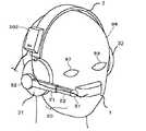
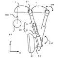
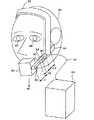
図1は、本発明の実施の形態1の頭部装着型画像表示装置の構成を示す上面図であり、図2は、図1の頭部装着型画像表示装置を頭部装着用品に取り付けた状況を示す斜視図であり、図3は、図2の頭部装着型画像表示装置付き頭部装着用品を使用者の頭部に装着した状態を示す斜視図である。
【0049】
なお、図1〜図3は使用者が右目が利き目であり、右目で頭部装着型画像表示装置に表示された画像を見る場合である。左目で画像を見る場合については、図11、12を用いて後述する。
【0050】
図1〜図3において、1は本実施の形態の表示ユニットであり、使用者の右目97の視軸500上または視軸近傍に映像信号に基づく画像の表示面を形成する。表示ユニット1は、表示ユニット1が使用者の右目の視軸500に近い位置である場合と、表示ユニット1が使用者の左目の視軸に近い位置である場合では、表示面に表示される画像の上下を反転させる。なお、表示ユニット1については、図6を用いて内部構成を後述する。
【0051】
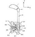
また、20は溝形状の外部摺動部21と溝に嵌合する形状の内部摺動部22からなる伸縮自在のアームであり、後述するように一端は第2連結機構部52を介してイヤーパッド31と連結され、他端は第1連結機構部51を介して表示ユニット1と連結され、少なくとも表示ユニット1を使用者の右目97の近傍に配置させる長さを有する。3は使用者の頭部99の側面から頭頂部を略半周に渡ってバンド状に巻回させる頭部保持部材であり、可撓性板状部材で構成される。頭部保持部材3の両先端部近傍には、イヤーパッド31(図2、3では右耳側)、32(図2、3では左耳側)が設けられる。頭部保持部材3と各イヤーパッド31、32は、例えば、音楽あるいは会議の音声等を聞くオーディオヘッドホンであり、頭部装着用品の一つである。イヤーパッド31、32の内部には、スピーカ等の発音装置311、321が設けられる、図示したオーディオヘッドホンは、使用者の頭部99の左右を保持すると共に頭頂部を保持することで頭部に着脱自在に装着される。
【0052】
アーム20の一方(頭部99の顔面側:内部摺動部22)の先端部には、第1連結機構部51が設けられる。第1連結機構部51は、表示ユニット1の一方の側面部とアーム20の一端部とが連結される部位に設けられる。第1連結機構部51は、表示ユニット1の側面部における表示面の上下方向の中心線を延伸させた位置と、アーム20の一端部におけるアーム幅方向の中心位置とで連結し、表示ユニット1が使用者の右目97に対して、上下回動方向の自由度θx1と、近接/離遠回動方向の自由度θz1を有している。また、第1連結機構部51は、表示ユニット1を、その向きを調整した後に任意位置(任意角度)で停止させることができる。
【0053】
本実施の形態の第1連結機構部51は、表示ユニット1を顔の上下方向に回動θx1させる軸Xに直交し、右目97近傍の顔表面に対して近接方向と離遠方向に回動θz1する軸Zに加え、表示ユニット1の遠方端を上下させる方向に回動θyする軸Yを有し、回動方向の自由度が3である球面連結機構になっているが、回動方向の自由度が2である(回動方向θx、θzに回動可能)2軸連結機構を用いても良い。なお、第1連結機構部51において球面連結機構の球面形状は、表示ユニット1の表示面を右目97の視軸に直交する角度に近づけるように調整する範囲で形成される。
【0054】
アーム20の他方(頭部99の後頭部側:外部摺動部21)の先端部には、第2連結機構部52が設けられる。第2連結機構部52は、頭部保持部材3の一端部に設けられたイヤーパッド31と連結される部位に設けられる。第2連結機構部52は、イヤーパッド31の幅方向の中心位置と、アーム20側の他端部(外部摺動部21)におけるアーム幅方向の中心位置とで連結し、使用者の右目97近傍の顔表面に対して、上下回動方向の自由度θxと、近接/離遠回動方向の自由度θzと、側面上下回動方向の自由度θyを有している。また、第2連結機構部52は、表示ユニット1の向きを調整した後のアーム20を任意位置(任意角度)で停止させることができる。
【0055】
第2連結機構部52とイヤーパッド31との連結方法は、汎用あるいは公知の機械的連結手段や接合手段から、時と場合に応じて適した手段を任意に選択して用いれば良い。図1では、一例として、両面テープ61を連結部材として用いる場合を示したが、例えば、イヤーパッド31側にスリットを設け、第2連結機構部52側にレールを設けてスライドさせてはめ込む方法や、マジックテープ(登録商標)等を用いて連結する方法の方が、頭部装着用品としての頭部保持部材3とイヤーパッド31、32を変更する場合にはさらに容易となる。あるいは、連結方法としては、取付ネジを用いて、第2連結機構部52をイヤーパッド31に取り付ける方法を用いても良く、他の汎用あるいは公知の方法を用いても全く問題は無い。
【0056】
また、頭部保持部材3の任意位置には、表示ユニット1の表示面に映像信号に基づく画像を形成させる駆動回路等の電気回路が内蔵される回路ボックス302が配置(保持)される。回路ボックス302の表面には、表示ユニット1に表示される画像の上下を反転させる切替スイッチ305が設けられている。回路ボックス302を頭部保持部材3に配置することで表示ユニット1を軽量化でき、第1連結機構部51および第2連結機構部52に必要な操作力を減少させることができる。
【0057】
本実施の形態ではアーム20自身に、アーム20の長辺方向(伸縮方向)の長さを調整する摺動部を有している。アーム20の長さ調整用摺動部は、アーム20自身に限らず、第2連結機構部52、あるいは、第1連結機構部51に設けても良い。アーム20は、内部摺動部22を外部摺動部21中にY軸方向に押し込むことと、内部摺動部22を外部摺動部21中からY軸方向に引き出すことにより、長さを伸縮自在に調節することができる。これにより、右目97と表示ユニット1との距離を調節範囲内で自由に設定することができる。
【0058】
本実施の形態の第2連結機構部52は、接続部位の一方の少なくとも表面を球面形状として、回動方向の自由度が3である(回動方向θx、θy、θzに回動可能)球面連結機構になっているが、表示ユニット1を顔の上下方向に回動θxさせる軸Xに直交し、右目97近傍の顔表面に対して近接方向と離遠方向に回動θzする軸Zを有し、回動方向の自由度が2である2軸連結機構を用いても良い。なお、第2連結機構部52における球面連結機構の球面形状は、表示ユニット1の表示面を右目97の視軸に直交する角度に近づけるように調整する範囲で形成される。
【0059】
第2連結機構部52は、頭部保持部材3に対するアーム20の保持角度を、表示ユニット1が使用者の右目97の視軸に近い位置で使用される場合と、表示ユニット1が使用者の左目98の視軸に近い位置で使用される場合と、の双方の場合に対応する角度に設定可能であり、その設定角度付近で回動可能であるように連結する。
【0060】
第2連結機構部52は、図1のように球面連結機構を構成することで、図2に示したように回動方向θxおよび回動方向θzに回動することができ、さらに回動方向θyにも回動することができる。また、この凸球面部901の球面形状は、少なくとも表示ユニット1の表示面を右目97の視軸に直交する角度に近づける範囲内を自在に可動できる範囲で設けられる。また、回動方向θxについては、頭部装着型画像表示装置を右目に装着する場合と、左目に装着する場合とでは、頭部保持部材3に対する表示ユニット1の前後位置が入れ替わるため、支軸に合わせる調整のみである回動方向θyおよび回動方向θzに比べて回動角度の変動範囲を大きくする必要がある。これについては図11を用いて後述する。
【0061】
また、303は、回路ボックス302から表示ユニット1へ信号を伝達するケーブルであり、304は、映像ソース(図示せず)から回路ボックス302へ映像信号および音声信号を伝達するケーブルである。また、ケーブル304の先には、表示ユニット1を表示させるための電源となるバッテリや画像表示の制御回路等を内蔵する不図示の制御ボックスがあり、回路ボックス302は、ケーブル304を介してその制御ボックスと接続されている。
【0062】
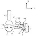
ここで、図1を用いて第2連結機構部52の内部構成を説明する。図1の球面連結機構である第2連結機構部52において、901はイヤーパッド31と接続する部分であると共に球面連結機構の一部となる凸球面部である。902は凸球面部901に当接しうる凹球面部を有するブロックである。903は、ブロック902、および、凸球面部901を貫通し、Cブロック904に螺合するスクリューである。905はブロック902とスクリュー903との間に挟持されたスプリングである。
【0063】
また、アーム20の他方(頭部99の後頭部側:外部摺動部21)の先端部は、ブロック902に固定される。ブロック902とスクリュー903との間に押圧して挟持されるスプリング905の効果により、凸球面部901は、Cブロック904とブロック902の凹球面部とを凹圧挟持し、イヤーパッド31に対して、外部摺動部21を適度な摩擦ブレーキ力で回動および保持する事ができ、任意の位置に調整した後にその位置で保持することができる。
【0064】
ここで、本実施の形態では、第1連結機構部51および第2連結機構部52の2箇所に、回動方向の自由度が2である(回動方向θx、θzに回動可能)2軸連結機構、あるいは、回動方向の自由度が3である(回動方向θx、θy、θzに回動可能)球面連結機構を採用している理由を説明する。
【0065】
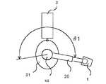
図4は、人間の頭の平面寸法における眼球の位置と側頭部の傾きを示す平面図であり、図5は、人間の頭の側面寸法における眼球の位置と表示ユニット1の傾きを示す側面図である。
【0066】
図4および図5において、500は、右目97の視軸を示し、700は、表示ユニット1の表示画像の中心光軸(映出光軸)を示す。本実施の形態の頭部装着型画像表示装置を使用して良好(鮮明)な画像を得ようとする場合には、視軸500と映出光軸700は完全に一致させることが望ましいが、それができない場合でも、少なくとも表示ユニット1の表示面を目の視軸500に直交する角度に近づける必要がある。
【0067】
しかし、人間の頭のサイズは千差万別であり、頭部装着型画像表示装置を正面視で使用する場合(図5(a)の場合)のみを想定しても、例えば、図4に示したように、耳に対する眼球までの左右位置Cにはバラツキがあり、さらに、イヤーパッド31が当接する側頭部の傾きθ10についてもバラツキがある。また、図5に示したように、耳に対する眼球までの前後位置A、および、上下位置Bについてもバラツキがある。
【0068】
また、頭部装着型画像表示装置の使用方法としては、上記した図5(a)の正面視の場合のみでなく、例えば、図5(b)に示したように視線を下目にして画像を見る場合、あるいは、図5(c)に示したように視線を上目にして画像を見る場合があり、また、図4に示したような横目で画像を見る場合があり、表示ユニット1は、その全ての場合に対して視軸500と映出光軸700を一致させるか、少なくとも表示面を目の視軸500に直交する角度に近づける必要がある。
【0069】
上記から、使用中のイヤーパッド31または第2連結機構部52の角度に対する表示ユニット1の角度は、限度があるとはいえ千差万別であり、その両者の間隔も限度内で千差万別である。
【0070】
例えば、上記した特開平11−327460号公報に示された従来の頭部装着型画像表示装置では、アームの一端の連結機構部に球面連結機構を採用しているのみであるので、図4あるいは図5に示した位置A〜Cのバラツキ、および、図5(b)あるいは図5(c)に示した使用方法の違いによる視線方向の変化に対応することは不可能である。
【0071】
それに対して本実施の形態では、アーム20の両端の第1連結機構部51および第2連結機構部52の2箇所に、回動方向の自由度が3の連結機構を採用し、さらに、アーム20に伸縮機能を持たせることによって、上記した位置A〜Cのバラツキ、および、視線方向の変化に対応して、視軸500と映出光軸700を一致させるか、表示面を目の視軸500に直交する角度に近づけられるようにしている。これにより、本実施の形態では、複数の人の顔の各寸法のバラツキや視線方向の変化に対応でき、表示ユニット1により鮮明に表示画像を視認することができる。
【0072】
図6は、図1〜図5の表示ユニット1の内部構成を示す2面(上面、側面)図である。
【0073】
表示ユニット1内には、映像信号に基づく画像を形成して表示する液晶表示板(LCD)102と、LCD102のバックライト光源となる発光ダイオード(LED)104と、LED104の出射光の放射方向をLCD102の方に向けて適度に拡散させながら反射させる拡散反射板103と、LCD102で形成された画像を、使用者の右目97に向けて適度に拡大させながら反射させるプリズムレンズ101を有している。また、プリズムレンズ101における表示面がウインドウ105であり、ウインドウ105の上下方向の中心(画像中心高)と左右方向の中心の交点が映出光軸700となり、これを目の視軸500と一致させることが、鮮明な画像を視認するためには必要となる。
【0074】
表示ユニット1は、図6の上面図からわかるように、表示面を有するLCD102、光源となるLED104、および、光学部品であるプリズムレンズ101と拡散反射板103が顔の横方向に並んで配置されており、顔の表面の横方向に沿って細長い形状となっている。このため、表示ユニット1の顔の縦方向の寸法は、図17に示した従来の表示ユニットの寸法よりも小さくなる。
【0075】
本実施の形態の表示ユニット1では、上記した配置で縦寸法が小型化されることにより、使用する片目の上下の視野を全て遮ってしまうことがなくなり、表示ユニット1を使用者の視野の一部に配設することができる。従って、表示ユニット1の使用時には、使用者は、周囲の視野を確保しつつ、見たいときだけ画像を視認するという使い方ができるので、歩行中や作業中の安全性を損なうことがなくなる。また、表示ユニット1では、効き目である使用する片目の視野を全て覆うことにより、使用者が圧迫感や閉塞感を感じることを無くすことができる。
【0076】
使用者は、右目97の視軸500上に、プリズムレンズ101(ウインドウ105)の中心である映出光軸700が一致するように向きを調整することで、良好な画像を視認することができるようになる。向きの調整は、第1連結機構部51の自由度が3である(回動方向θx、θy、θzに回動可能)球面連結機構と、第2連結機構部52の自由度が3である(回動方向θx、θy、θzに回動可能)球面連結機構を連動させて用いればよい。また、第1連結機構部51については、少なくとも上下回動方向の自由度θx1と近接/離遠回動方向の自由度θz1を有する2軸連結機構としても良い。
【0077】
図7は、図1〜図6の第1連結機構部51の内部構成を示す斜視図である。
【0078】
第1連結機構部51は、表示ユニット1の一端に形成された連結用球面部1000と、アーム20の内部摺動部22の先端部222に形成された半球面部222aと、連結用球面部1000の押さえ板221に形成された半球面部221aとで構成されている。半球面部222aと半球面部221aとは、連結用球面部1000を挟持して対向する位置に設置されている。押さえ板221は、スクリュー223と波ワッシャ224によって、アーム20の内部摺動部22に押圧固定される。
【0079】
押さえ板221は、波ワッシャ224をスクリュー223が押圧することによって、半球面部221aと半球面部222aにより所定の押圧力で連結用球面部1000を挟持する。従って、内部摺動部22の伸縮方向に対して表示ユニット1を適度な摩擦力(ブレーキ力)で回動させ、回動後はその位置で保持させることができる。
【0080】
なお、連結用球面部1000は、表示ユニット1よりもより顔の外側(使用者の顔のより側面方向側)に位置するように配設される。また、連結用球面部1000の中心は、表示ユニット1の上下(高さ)方向の中心線と一致するように形成され、従って、図6の画像が表示されるウインドウ105の上下方向の中心線とも連結用球面部1000の中心は一致する。
【0081】
第1連結機構部51は、図7のように構成することで、図2に示したように回動方向θx1および回動方向θz1に自在に回動することができる。
【0082】
次に本実施の形態の頭部装着型画像表示装置の動作について説明する。
まず、入力する映像信号に基づいて表示ユニット1に画像が表示される動作について説明する。
【0083】
例えば、不図示のコンピュータあるいはビデオ装置等の映像ソースから入力信号(映像信号)が、不図示の制御ボックスおよびケーブル304等を介して回路ボックス302に入力されると、回路ボックス302では、入力した映像信号に対して、表示ユニット1に画像表示するために必要となる信号処理を施し、ケーブル303を介して表示ユニット1に送出する。表示ユニット1では、入力した信号に基づきLCD102に画像を形成し、LCD102の画像はLED104の放射光が拡散反射板103で反射された光によりプリズム101に投射され、ウインドウ105に画像が表示される。
【0084】
ウインドウ105を通過した画像の光は、使用者の右目97の瞳孔を通過して網膜上に画像を結像させる。使用者は、このようにして画像を認識する。
【0085】
図6では、視軸500と映出光軸700が一致する場合を示し、ウインドウ105にから右目97に投影される画像の右目97への入射部におけるスポット径Dは、一般的に瞳孔径よりも若干大きい値に設定される。従って、視軸500と映出光軸700のずれ量が大きくなると、有効な光束の一部が欠ける場合があり、その場合には、画像の周囲にけられ、あるいは、暗部等の不良部が発生する。
【0086】
以上から、頭部装着型画像表示装置の表示ユニット1は、顔の寸法や目の配置や使用角度にバラツキがある複数の人の何れが装着しても良好(明確)な画像表示を認識するためには、目との距離や視軸との角度を自在に調節することにより、視軸500と映出光軸700を極力一致させる必要があることが理解できる。
【0087】
次に、使用者が効き目に装着する動作について説明する。
本実施の形態の頭部装着型画像表示装置の使用者は、イヤーパッド31および32を持って、可撓性を有する頭部保持部材3を自身の頭部99の幅に合わせて弾性変形させて押し広げ、頭頂部の略半周に渡って巻回させ、イヤーパッド31が右耳上に配置され、イヤーパッド32が左耳上に配置されるように装着する。
この時、図2に示すようにイヤーパッド31が使用者の頭部99の左耳を覆うように被さり、イヤーパッド32は右耳を覆うように被さり、頭部保持部材3が頭頂部に巻き回されることで、頭部装着型画像表示装置が下方向へ落下することを防止する。
【0088】
図3の右目に装着した場合の使用状態を示した図では、使用者が頭部保持部材3を装着後、表示ユニット1を使用者にとって最も画像が見やすい任意の位置に配置した状態を示している。すなわち、XYZ軸を有する3次元空間上で、使用者の右目97の視線500と、表示ユニット1の表示面に投影された画像の光軸の中心(映出光軸700)とを一致させるように、表示ユニット1のX、Y、Z座標を定める。この場合の可動部は、第1連結機構部51(回動方向θx、回動方向θyおよび回動方向θz)、第2連結機構部52(回動方向θx、回動方向θy、回動方向θz、および、摺動方向Y)であり、各連結機構部51、52の回動方向θx、θy、θzの姿勢(方向角)等が座標決定により定められる。
【0089】
図8は、図1〜図5の頭部装着型画像表示装置で表示ユニットのX座標位置を設定する動作を示す図である。
【0090】
まず、使用者は表示ユニット1を持って、アーム20を第2連結機構部52を支軸としてθz2方向に回動(揺動)させると共に、第1連結機構部51を支軸としてθz1方向に回動(揺動)させることで、表示ユニット1は右目97の支軸500とウインドウ105が直交する姿勢を変化させずに、X座標方向の位置決めを実施することができる。
【0091】
図9は、図1〜図5の頭部装着型画像表示装置で表示ユニットでのZ座標位置を設定する動作を示す側面図である。
【0092】
まず、使用者は表示ユニット1を持って、アーム20を第2連結機構部52を支軸としてθx2方向に回動(揺動)させると共に、第1連結機構部51を支軸としてθx1方向に回動(揺動)させることで、表示ユニット1は右目97の支軸500とウインドウ105が直交する姿勢を変化させずに、Z座標方向の位置決めを実施することができる。
【0093】
図10は、図1〜図5の頭部装着型画像表示装置で表示ユニットでのY座標位置を設定する動作を示す平面図である。
【0094】
まず、使用者は表示ユニット1を持って、アーム20の内部摺動部22を、外部摺動部21中にY軸方向に押し込むか、外部摺動部21中からY軸方向に引き出すように摺動変位させると共に、第1連結機構部51を支軸としてθz1方向に回動(揺動)させ、第2連結機構部52を支軸としてθz2方向に回動(揺動)させることで、表示ユニット1は右目97の支軸500とウインドウ105が直交する姿勢を変化させずに、Y座標方向の位置決めを実施することができる。
【0095】
また、例えば、図4に示したようにアーム20の伸縮する軸方向が、使用者の頭部99の前後の軸であるY軸方向と傾きを有している場合(使用者の頭部99の側面とアーム20が平行の場合にはその傾きはθ10となる)であっても、第1連結機構部51のθz1方向の回動(揺動)と、第2連結機構部52のθz2方向の回動(揺動)を併用させることで、表示ユニット1は姿勢を変化させずに、Y座標方向の位置決めを実施することができる。
【0096】
図8〜図10を用いて上記したように、本実施の形態1の表示ユニット1は、姿勢を変化させずにX座標、Y座標、Z座標の各方向に位置決めできるので、XYZ空間上(XYZ座標系)における任意の位置に姿勢を変化させずに配置することができることがわかる。
【0097】
さらに、アーム20の伸縮、第1連結機構部51の3方向の回動(揺動)と、第2連結機構部52の3方向の回動(揺動)を併用することにより、本実施の形態1の表示ユニット1は、XYZ空間上(XYZ座標系)で、視軸500に対して任意の角度を取ることができることがわかる。さらに、位置決めする際のブレーキ力は、第1連結機構部51と第2連結機構部52で分担するため、従来よりも少ない力で表示ユニット1を位置決めすることができる。
【0098】
以上から、本実施の形態1の表示ユニット1は、XYZ軸を有する3次元空間上で、使用者の右目97の視線500と、表示ユニット1の表示面に投影された画像の光軸の中心(映出光軸700)とを一致させるように、表示ユニット1のX、Y、Z座標を定めることができることが確認できる。
【0099】
図11は、右目に装着していた本実施の形態の頭部装着型画像表示装置を左目に装着する前にアーム20を回動させる様子を示す側面図である。
【0100】
右目97で使用していた表示ユニット1を左目で使用する前に、第2連結機構部52を支軸としてX軸周りにアーム20を回動(回動方向θx2)させる。その場合、頭部保持部材3とイヤーパッド31、32は必要に応じて取り替えてから実施する。
【0101】
図12は、図2の右目用の頭部装着型画像表示装置を左目用に変形させた場合を示す斜視図である。
【0102】
本実施の形態では、第1連結機構部51は、表示ユニット1の側面部における表示面の上下方向の中心線を延伸させた位置と、アーム20(内部摺動部22)の一端部におけるアーム幅方向の中心位置とで連結し、第2連結機構部52は、イヤーパッド31(頭部装着用品)における使用者の右耳の近辺部の幅方向の中心位置と、アーム20(内部摺動部22)側の他端部におけるアーム幅方向の中心位置とで連結するため、図12のようにアーム20を反転させた場合でも、形状の左右が反転するのみで意匠性が損なわれず、左目用と右目用で個別に専用の接続治具等が必要にならない。
【0103】
但し、このままでは、表示ユニット1に表示される画像の上下が反対になってしまうので、回路ボックス302の表示画像上下反転切替えスイッチ305を操作して、表示ユニット1に表示される画像の上下が正しく表示されるようにする。その後の、表示ユニット1の位置および角度の調整動作については上記した内容と同様であるので説明を省略する。また、イヤーパッド31、32の音声がステレオ音声で異なっている場合には、発音装置311、321に入力される音声信号を入れ替えればよい。
【0104】
また、本実施の形態の頭部装着型画像表示装置を収納する際には、図11を用いて上記したように、第2連結機構部52を用いて、アーム20は頭部保持部材3と平行した配置まで回動できるため、頭部保持部材3およびイヤーパッド31、32からわずかな収納スペースの増加のみで収納することができる。
【0105】
また、本実施の形態の第1連結機構部51および第2連結機構部52は、自由度が高いため、使用者の使用する片目の視線500と映出光軸700とを一致させる調整作業が容易であり、ブレーキ力を比較的小さくできる第1連結機構部51に可能な範囲の調整時の回動は第1連結機構部51に実施させ、ブレーキ力を比較的大きい第2連結機構部52では、第1連結機構部51ではできない範囲の調整時の回動のみを実施するように分担することで、表示ユニット1の位置調整作業を容易、かつ、きめ細やかに実施することができ、各連結機構部の回動範囲および操作力を低減させることができる。
【0106】
また、第1連結機構部51が表示ユニット1に表示される画像の高さ方向の中心位置と一致するよう(中心線上)に形成され、第2連結機構部52が保持手段3の巾方向の中心位置と一致するよう(中心線上)に形成されていることから、図11、12のように反転させても、左目に装着時と右目に装着時とで操作環境が左右対称になるのみであるので、どちらの目が効き目の人にも同じ使用環境を提供できる。また、左右の何れの目に装着した場合でも、意匠的に左右反転するのみであるので何れか一方の装着者の美観が損なわれることがない。
【0107】
また、本実施の形態では、前の使用者が右目97に装着していた場合でも、次の使用者は、部品を組替えることなく、アーム20を回動させるのみの容易な操作で表示ユニット1を左目98の前に配置、すなわち、頭部装着型画像表示装置を左目に装着することができる。
【0108】
このように、本実施の形態の頭部装着型画像表示装置は、効き目が左目と右目の何れかである複数の使用者で共有して使用する場合でも、各自用の頭部装着用品(頭部保持部材3およびイヤーパッド31、32)を容易に変更して他人の使用したものが直接に肌に触れないようにでき、使用する片目と表示ユニットとの距離を適切に調整する機能を頭部保持部材3等に備えさせる必要が無く、左目用と右目用で個別に専用の接続治具等が必要にならず、非使用時に収納する際にも、頭部保持部材3およびイヤーパッド31、32からの収納スペースの増加を少なくして収納性を良くし、右目用から左目用あるいは逆にする場合の部品を組み換えを無いので手間が少なく、表示ユニットを位置決めする際の操作力が少なくてすみ、さらにそれにより位置決め時に、頭部装着用品の頭部への拘束力が小さい場合でも頭部保持部材自体を動かしてしまうことがなくなる。
【0109】
実施の形態2.
実施の形態1では、各自用の頭部装着用品(頭部保持部材3およびイヤーパッド31、32)と、頭部装着型画像表示装置を分離できるようにして、頭部装着型画像表示装置を複数の使用者で共有使用する場合でも、他人の使用したものが直接に肌に触れないようにできたが、必ずしも、頭部装着用品(頭部保持部材3およびイヤーパッド31、32)と、頭部装着型画像表示装置は分離させる必要はなく、例えば、頭部装着用品の表面の肌に触れる部分のみのカバーを準備し、そのカバーのみを変更できるようにすれば、頭部装着用品と頭部装着型画像表示装置は一体化されていても良いことになる。
【0110】
以下に示す実施の形態2では、頭部装着用品のイヤーパッド(使用者の耳の近辺部を覆う形状)と頭部装着型画像表示装置を一体化した場合を説明する。
【0111】
図13は、本発明の実施の形態2の頭部装着型画像表示装置を示す平面図である。
なお、図1〜図12の実施の形態1と、本実施の形態2との相違点は、イヤーパッド31と第2連結機構部53を一体的に形成したのみであり、他の構成は全て実施の形態1と同様であり、頭部保持部材3等は図への記載を省略している。
【0112】
この場合、他人の使用したものが直接に肌に触れないようにするには、例えば、片面に接着と剥離が容易な接着力の弱い接着剤等を塗布した紙、布、不織布、高分子化合物シート、金属シート等の任意の薄膜状シートを用いて頭部装着用品の表面の肌に触れる部分を覆った後、頭部装着型画像表示装置と一体化された頭部装着用品を使用者の頭部に装着すれば良い。
【0113】
また、他人の使用したものが直接に肌に触れることが問題でない場合には、薄膜状シートを用いずに、そのまま図13の頭部装着型画像表示装置を複数人数で共有すれば良い。
【0114】
本実施の形態では、イヤーパッド31と第2連結機構部53を一体的に形成しているので、別個に製造する場合よりも工数とコストを削減でき、連結するためのスペースを節約することができ小型化できる。また、使用時に、各使用者が個別に保有する部品が減少し、変更が薄膜状シートのみと容易になるので、使用時の工数とランニングコストを減少させることができ、小型化できることから収納スペースも減少させることができる。
【0115】
このように、本実施の形態では、頭部装着型画像表示装置複数の使用者の共用部品部分を増加させて、製造時の工数、部品スペースおよびコストを減少させ、使用時の工数、収納スペースおよびランニングコストを減少させることができる。
【0116】
実施の形態3.
実施の形態1、2では、アーム20を内部摺動部22と外部摺動部21に分割して摺動させることで伸縮機能(Y方向位置調整機能)を持たせた場合について説明したが、伸縮機能は必ずしもアームに持たせる必要はなく、例えば、アームの長さは固定値にして、第1連結機構部または第2連結機構部に伸縮機能を持たせても良い。
【0117】
以下に示す実施の形態3では、伸縮機能(Y方向位置調整機能)を第2連結機構部に持たせた場合を説明する。
【0118】
図14は、本発明の実施の形態3の頭部装着型画像表示装置を示す平面図である。
なお、図1〜図12の実施の形態1および図13の実施の形態2と、本実施の形態との相違点は、アーム25の長さは固定長であり、第1連結機構部51が形成される一端と逆の他端近傍には、鋸歯状の係止部227が形成されており、また、他端はブロック225を貫通している。
【0119】
ブロック225は、凹球面部902を有し、アーム25が貫通する貫通孔(または貫通溝)を備え、貫通孔内には、アーム25の係止部227の各歯と係合するクリックバネ230が設置されている。
【0120】
また、ブロック225は、貫通孔を設けることで、スクリュー903はブロック225を貫通してCブロック904に螺合することが難しくなり、スプリング905も、ブロック225とスクリュー903との間に挟持されることが難しくなる。
【0121】
そこで、本実施の形態では、スクリュー903とスプリング905をイヤーパッド31の内部側に配置し、スクリュー903はCブロック904を貫通してブロック225に螺合するように構成した。
【0122】
従って、本実施の形態の第2連結機構部55は、凹球面部902と貫通孔内にクリックバネ230を有するブロック225と、鋸歯状の係止部227が形成されてクリックバネ230と係合する固定長のアーム25と、イヤーパッド31と一体に形成された凸球面部901と、スクリュー903と、スプリング905、および、Cブロック904から構成されている。
【0123】
本実施の形態の表示ユニットの位置及び角度を設定する動作は、実施の形態1および2とはX座標位置とZ座標位置を設定する動作については同様であるので記載を省略し、Y座標位置を設定する動作のみ説明する。
【0124】
図15は、図14の頭部装着型画像表示装置で表示ユニットでのY座標位置を設定する動作を示す平面図である。
【0125】
まず、使用者は表示ユニット1を持って、アーム25をブロック225の貫通孔中にY軸方向に押し込むか、ブロック225の貫通孔中からY軸方向に引き出させると共に、第1連結機構部51を支軸としてθz1方向に回動(揺動)させ、第2連結機構部55を支軸としてθz2方向に回動(揺動)させることで、表示ユニット1は右目97の支軸500とウインドウ105が直交する姿勢を変化させずに、Y座標方向の位置決めを実施することができる。
【0126】
また、実施の形態1と同様に、図4に示したようにアーム25の伸縮する軸方向が、使用者の頭部99の前後の軸であるY軸方向と傾きを有している場合(使用者の頭部99の側面とアーム25が平行の場合にはその傾きはθ10となる)であっても、第1連結機構部51のθz1方向の回動(揺動)と、第2連結機構部55のθz2方向の回動(揺動)を併用させることで、表示ユニット1は姿勢を変化させずに、Y座標方向の位置決めを実施することができる。
【0127】
このように本実施の形態でも、実施の形態1および2と同様な効果を得ることができ、さらに、係止部227とクリックバネ230との係合により、Y座標方向の位置決め作業に必要な操作力を減少させることができ、アームを2分割しないでアームに係止部227を設けるのみであるのでアームの伸縮方向の調整範囲を2分割する場合よりも増加させることができる。
【0128】
実施の形態4.
実施の形態1〜3では、各自用の頭部装着用品として、頭部保持部材3およびイヤーパッド31、32を揺するオーディオヘッドホンを用いていたが、本発明はヘッドホン状の頭部装着用品のみでなくとも実施可能であり、例えば、硬質の帽子あるいはヘルメット状の頭部装着用品にも連結することができる。
【0129】
以下に示す実施の形態4では、第2連結機構部52を連結する頭部装着用品として頭部の両耳より上部を覆うヘルメットを利用する場合を説明する。
【0130】
図16は、本発明の実施の形態4の頭部装着型画像表示装置を示す平面図である。
なお、図1〜図12の実施の形態1、および、図13の実施の形態2と本実施の形態と共通する表示ユニット1、アーム20、回路ボックス302、ケーブル304、切替スイッチ305、第1連結機構部51および第2連結機構部52については説明を省略して相違点のみを説明する。
【0131】
図16中で、3000は土木建設工事等に用いられる汎用のヘルメットであり、3500は一端に第2連結機構部52が連結されると共に、他端にはスクリュー3501によりクランパ3600が取り付けられる保持部材である。
【0132】
連結部材3500とクランパ3600でヘルメットにおける使用者右耳の上部にあたる端部を挟持し、スクリュー3501を締めることにより、頭部装着型画像表示装置をヘルメットに固定する。
【0133】
回路ボックス302は、例えば、連結部材3500に、両面テープ等の任意の固定手段により固定しておけばよい。また、ヘルメットの場合には、上記した各実施の形態のオーディオヘッドホンにおけるスピーカ等の発音装置が無くなることから、例えば、スピーカ3100を追加する場合には、連結部材3500の内側(裏面:人側)に両面テープ等の任意の固定手段により固定する。
【0134】
その他の構成および動作については、上記した各実施の形態1、2と同様であるので説明を省略する。
【0135】
本実施の形態で使用する汎用のヘルメットは、工事現場等では、一般的に一人に一個づつ支給されるものであり、別途に個別の頭部装着用品として購入する必要はない。また、連結部材3500の内側(裏面)にスピーカ3100を追加できるので、別途にイヤホン手段等を耳に装着する煩わしさもなく、頭部装着型画像表示装置を使用中でも、音声の指令情報等を聴取することができる。
【0136】
このように本実施の形態では、一般的に個別に使用されるヘルメットに容易に頭部装着型画像表示装置を連結することができるので、複数の使用者が肌に触れる部分を別にして頭部装着型画像表示装置を共有する場合でも必要なコストが少なくてすみ、また、ヘルメット以外の任意の硬質の帽子型頭部装着用品にも連結することができる。
【0137】
また、実施の形態1〜3では、頭部保持部材3を使用者の頭部99における頭頂部に巻き回すようにしたが、例えば、前頭額部、あるいは、後頭部に巻き回すように構成しても良い。また、実施の形態4では、頭部の両耳より上部を覆うヘルメットを利用したが、例えば、両耳を覆う形状のヘルメットや、フレーム形状あるいは開口部を多数有するヘッドギア等に本実施の形態を連結するように構成しても良い。
【0138】
また、上記した各実施の形態では、頭部保持部材3あるいは連結部材3500に回路ボックス302を設けたが、回路ボックス302は、他の場所、例えば、イヤーパッド31上や第2連結機構部52、53、55等と連結して設けるように構成しても良く、あるいは、表示ユニット1、不図示の制御ボックス等に内蔵させても良い。
【0139】
【発明の効果】
本発明は、以上説明したように構成されているので、以下に示すような効果を奏する。
【0140】
請求項1、11、13、14の本発明では、効き目が左目と右目の何れかである複数の使用者で共有して使用する場合でも、各自用の頭部装着用品を容易に変更して他人の使用したものが直接に肌に触れないようにでき、表示ユニットを位置決めする際の操作力が少なくでき、位置決め時に、頭部装着用品の頭部への拘束力が小さい場合でも頭部保持部材自体を動かしてしまうことを無くすことができる。
【0141】
請求項2〜5の本発明では、使用する片目と表示ユニットとの距離を適切に調整する機能を頭部保持部材に備えさせる必要を無くすことができる。
【0142】
請求項6の本発明では、表示ユニットの縦寸法が小型化されることにより、使用する片目の上下の視野を全て遮ってしまうことがなくなり、表示ユニットを使用者の視野の一部に配設することができる。従って、表示ユニットの使用時には、使用者は、周囲の視野を確保しつつ、見たいときだけ画像を視認するという使い方ができるので、歩行中や作業中の安全性を損なうことがなくなる。また、効き目である使用する片目の視野を全て覆うことによる使用者が感じる圧迫感や閉塞感を無くすことができる。
【0143】
請求項7の本発明は、回路ボックスを頭部保持部材に配置することで表示ユニットを軽量化でき、第1連結機構部および第2連結機構部に必要な操作力を減少させることができる。
【0144】
請求項8〜10の本発明では、左目用と右目用で個別に専用の接続治具等の必要性を無くすことができ、非使用時に収納する際にも、頭部保持部材等からの収納スペースの増加を少なくして収納性を良くすることができ、右目用から左目用あるいは逆にする場合の部品を組み換えを無くして手間を少なくできる。
【0145】
請求項12の本発明では、イヤーパッドと第2連結機構部を一体的に形成しているので、別個に製造する場合よりも工数とコストを削減でき、連結するためのスペースを節約することができ小型化でき、使用時に、各使用者が個別に保有する部品が減少し、使用時の工数とランニングコストを減少させることができ、小型化できることから収納スペースも減少させることができる。
【0146】
請求項15の本発明では、別途にイヤホン手段等を耳に装着する煩わしさもなく、使用中でも音声の指令情報等を聴取することができる。
【図面の簡単な説明】
【図1】本発明の実施の形態1の頭部装着型画像表示装置の構成を示す上面図である。
【図2】図1の頭部装着型画像表示装置を頭部装着用品に取り付けた状況を示す斜視図である。
【図3】図2の頭部装着型画像表示装置付き頭部装着用品を使用者の頭部に装着した状態を示す斜視図である。
【図4】人間の頭の平面寸法における眼球の位置と側頭部の傾きを示す平面図である。
【図5】人間の頭の側面寸法における眼球の位置と表示ユニットの傾きを示す側面図である。
【図6】図1〜図5の表示ユニットの内部構成を示す2面(上面、側面)図である。
【図7】図1〜図6の第1連結機構部の内部構成を示す斜視図である。
【図8】図1〜図5の頭部装着型画像表示装置で表示ユニットのX座標位置を設定する動作を示す図である。
【図9】図1〜図5の頭部装着型画像表示装置で表示ユニットでのZ座標位置を設定する動作を示す側面図である。
【図10】図1〜図5の頭部装着型画像表示装置で表示ユニットでのY座標位置を設定する動作を示す平面図である。
【図11】右目に装着していた本実施の形態の頭部装着型画像表示装置を左目に装着する前にアームを回動させる様子を示す側面図である。
【図12】図2の右目用の頭部装着型画像表示装置を左目用に変形させた場合を示す斜視図である。
【図13】本発明の実施の形態2の頭部装着型画像表示装置を示す平面図である。
【図14】本発明の実施の形態3の頭部装着型画像表示装置を示す平面図である。
【図15】図14の頭部装着型画像表示装置で表示ユニットでのY座標位置を設定する動作を示す平面図である。
【図16】本発明の実施の形態4の頭部装着型画像表示装置を示す平面図である。
【図17】従来の頭部装着型画像表示装置の構成の例を示す図である。
【符号の説明】
1、84 表示ユニット、 3、91 頭部保持部材、 20、95 アーム、 21 外部摺動部、 22 内部摺動部、 31、32 イヤーパッド、 302 回路ボックス、 51、96 第1連結機構部、 52、53、55、94 第2連結機構部、 61 連結部材(両面テープ)、 85、303、304 ケーブル、 97 右目、 98 左目、 99 (使用者の)頭部、 101 プリズムレンズ、 102 液晶表示板(LCD:画像表示板)、 103 拡散反射板、 104 発光ダイオード(LED:光源)、 305 表示画像上下反転切替スイッチ、 311、312 発音装置(スピーカ)、 500 視軸、 901 凸球面部、 902 ブロック、 903 スクリュー、 904 Cブロック、 905 スプリング。[0001]
TECHNICAL FIELD OF THE INVENTION
The present invention is a display unit detachably attached to a user's head using a head holding member, and displays an image based on a video signal on or near the visual axis of one of the left and right eyes of the user. The present invention relates to a head-mounted image display device that forms a surface, and more particularly to a structure for connecting a head holding member and a display unit.
[0002]
[Prior art]
FIG. 17 is a diagram illustrating an example of a configuration of a conventional head-mounted image display device.
[0003]
The head-mounted image display device of FIG. 17 includes a
[0004]
In the
[0005]
The image displayed on the display surface of the
[0006]
The
[0007]
The braking force M1 (moment) in the rotating direction for stopping the
M1> W1 * L1 (1)
[0008]
If the weight W1 of the
[0009]
A more detailed example of the conventional head-mounted image display device shown in FIG. 17 is described in, for example, Japanese Patent Application Laid-Open No. H11-327460, but when the braking force M1 is increased, the position of the
[0010]
Generally, the
[0011]
In FIG. 17, the width of the
Even in the case of being folded and stored, a storage space for summing at least the width H2 of the
[0012]
In Japanese Patent Application Laid-Open No. H11-327460, a
[0013]
In Japanese Patent Application Laid-Open No. H11-327460, the user does not directly see the image displayed on the
[0014]
Next, the operation of the head mounted image display device of FIG. 17 will be described.
FIG. 17 shows a case where the
[0015]
In the case of FIG. 17, the
[0016]
In this case, the operation of bringing the display surface of the image of the
[0017]
An image displayed on the display surface of the
[0018]
When the head-mounted image display device shown in FIG. 17 is used with the
[0019]
In the case of Japanese Patent Application Laid-Open No. 11-327460, since the mirror protrudes from the
[0020]
In general, it is known that a head-mounted image display device to be used with one eye needs to be worn on the effect side of the user. For example, when such an image display device is not mounted on the effect side, the image display device is mounted on the opposite eye of the effect. However, since the opposite eye is an eye for observing the surrounding situation, the recognition degree of the information on the surrounding situation increases, and the image displayed on the image display device cannot be recognized well. Which eye (
[0021]
In general, a head-mounted image display device using an LCD distorts an image or darkens an image unless the user's line of sight is aligned with the center optical axis (projected optical axis) of the displayed image. Or a part of the surrounding image is blurred. However, since the size and shape of the human head are various, and the relative positions of the eyeball with respect to the head are also various, the position of the eyeball with respect to the head mounting means is also various and the adjustment range is wide, and the visual axis and the projection optical axis are different. Matching is not easy.
[0022]
In the case of Japanese Unexamined Patent Application Publication No. 11-327460, for example, when the position of the
[0023]
[Problems to be solved by the invention]
However, when the head-mounted image display device of FIG. 17 is shared and used by a plurality of users, the
[0024]
Further, for example, it is conceivable to attach the head-mounted image display device of FIG. 17 to a head-mounted article such as a headphone, a hard hat, or a helmet using a connection jig or the like. It is necessary to provide a function for appropriately adjusting the distance between the
[0025]
Further, when the head-mounted image display device shown in FIG. 17 is to be mounted on a general-purpose head-worn article, the shape and angle near the left ear and the shape near the right ear of the general-purpose head-worn article Since there is a difference between the angle and the angle, there is a problem that dedicated connection jigs and the like are separately required for the left eye and the right eye.
[0026]
In the conventional example shown in FIG. 17, when the head-mounted image display device is stored when not in use, at least the width H2 of the
[0027]
In the above-described conventional example, when the head-mounted image display device is changed from using the
[0028]
Further, in the above-described conventional example, when the restraining force of the
[0029]
Further, in the above-described conventional example, since the braking force M1 of the
[0030]
The head mounted image display device of the present invention has been made in order to solve the above-described problem, and has a plurality of persons whose effects are either the left eye or the right eye, and using a head mounted article for each person. An object of the present invention is to provide a head mounted image display device that can be easily shared.
[0031]
Another object of the present invention is to provide a head-mounted image display device that has good storage properties when not in use and allows easy replacement of parts even when changing the eyes of the user, or does not need to be rearranged. And
[0032]
In addition, even when the restraining force on the head of the head-mounted article is small, the head-mounted article itself does not move when holding the work to bring the display surface of the image of the display unit closer to the visual axis of the eye using the user. An object of the present invention is to provide a wearable image display device.
[0033]
[Means for Solving the Problems]
In order to solve the above-mentioned problem, a head-mounted image display device according to the present invention described in
[0034]
According to a second aspect of the present invention, in the head-mounted image display device according to the first aspect, at least one of the first connection mechanism and the second connection mechanism is configured to move the display unit in the vertical direction of the face. A two-axis coupling mechanism having an axis that is orthogonal to the axis to be rotated, and that rotates in a direction close to and away from the face surface near one eye and has two degrees of freedom in the direction of rotation. Features.
[0035]
According to a third aspect of the present invention, in the head-mounted image display device according to the first or second aspect, at least one of the first connecting mechanism and the second connecting mechanism is one of the connecting portions. At least the surface has a spherical shape, and is provided with a spherical coupling mechanism having three degrees of freedom in the rotating direction.
[0036]
According to a fourth aspect of the present invention, in the head mounted image display device according to the third aspect, the spherical shape of the spherical connecting mechanism used in the first connecting mechanism and the second connecting mechanism is at least a display unit. Is formed in a range in which the display surface can be freely moved within a range in which the display surface approaches an angle perpendicular to the visual axis of the eye.
[0037]
According to a fifth aspect of the present invention, in the head mounted image display device according to any one of the first to fourth aspects, at least one portion of the arm, the first connecting mechanism, and the second connecting mechanism is provided. Has a sliding portion for adjusting the length of the arm in the long side direction.
[0038]
According to a sixth aspect of the present invention, in the head-mounted image display device according to any one of the first to fifth aspects, the display unit includes a display surface, a light source, and an optical component arranged in a lateral direction of the face, It is characterized by being elongated in the horizontal direction.
[0039]
According to a seventh aspect of the present invention, in the head-mounted image display device according to any one of the first to sixth aspects, an image based on a video signal is formed on a display surface of the display unit separately from the display unit. When the driving circuit unit to be provided is provided, the driving circuit unit is installed at an arbitrary position of the head mounted article.
[0040]
According to an eighth aspect of the present invention, in the head-mounted image display device according to any one of the first to seventh aspects, the second connection mechanism unit sets a holding angle of the arm with respect to the head holding member to a display unit. Are used at a position near the visual axis of one eye of the user, and when the display unit is used at a position near the visual axis of the other eye of the user. , And are connected so as to be rotatable around the set angle.
[0041]
According to a ninth aspect of the present invention, in the head-mounted image display device according to the eighth aspect, the display unit uses the display unit at a position close to a visual axis of one eye of a user; When the display unit is used at a position close to the visual axis of the other eye of the user, the image displayed on the display surface is turned upside down.
[0042]
According to a tenth aspect of the present invention, in the head-mounted image display device according to the ninth aspect, the drive circuit unit includes a switch for inverting an image displayed on the display surface of the display unit upside down. It is characterized by.
[0043]
According to an eleventh aspect of the present invention, there is provided the head-mounted image display device according to any one of the first to tenth aspects, wherein the second connection mechanism and the left or right ear of the user in the head-mounted article. A connecting member is used to connect to any one of the peripheral portions.
[0044]
According to a twelfth aspect of the present invention, in the head-mounted image display device according to any one of the first to tenth aspects, the second coupling mechanism unit includes a left ear or a right ear of a user of the head-mounted article. Characterized in that it is formed integrally with any of the neighborhoods.
[0045]
According to a thirteenth aspect of the present invention, in the head-mounted image display device according to any one of the first to twelfth aspects, the head-mounted article has an audio headphone shape having an ear pad for covering an outer ear. And
[0046]
According to a fourteenth aspect of the present invention, in the head-mounted image display device according to any one of the first to twelfth aspects, the head-mounted article has a helmet shape that covers at least the upper part of the head from both ears. It is characterized by the following.
[0047]
According to a fifteenth aspect of the present invention, in the head-mounted image display device according to any one of the first to fourteenth aspects, the display image of the head-mounted image display device is provided inside the second coupling mechanism. And a sound output device for outputting a sound related to.
[0048]
BEST MODE FOR CARRYING OUT THE INVENTION
Hereinafter, embodiments of the present invention will be described with reference to the drawings.
FIG. 1 is a top view showing a configuration of a head-mounted image display device according to
[0049]
FIGS. 1 to 3 show a case where the user has the right eye as the dominant eye and looks at the image displayed on the head-mounted image display device with the right eye. The case of viewing the image with the left eye will be described later with reference to FIGS.
[0050]
1 to 3,
[0051]
[0052]
A
[0053]
The
[0054]
A
[0055]
As a method of connecting the second connecting
[0056]
A
[0057]
In the present embodiment, the
[0058]
The
[0059]
The second connecting
[0060]
The
[0061]
[0062]
Here, the internal configuration of the
[0063]
The other end of the arm 20 (the back side of the head 99: the outer sliding portion 21) is fixed to the
[0064]
Here, in the present embodiment, two degrees of freedom in the rotation direction are provided at the two positions of the
[0065]
FIG. 4 is a plan view showing the position of the eyeball and the inclination of the temporal region in the plane size of the human head, and FIG. 5 is a side view showing the position of the eyeball and the inclination of the
[0066]
4 and 5, 500 indicates the visual axis of the
[0067]
However, the size of the human head varies widely, and even if only the case where the head-mounted image display device is used in front view (case of FIG. 5A) is assumed, for example, FIG. As shown, the right and left positions C to the eyeball with respect to the ear vary, and the inclination θ10 of the temporal region with which the
[0068]
The method of using the head-mounted image display device is not limited to the case of the front view of FIG. 5A described above. Or the image may be viewed with the line of sight upward as shown in FIG. 5C, or the image may be viewed with the side view as shown in FIG. In all cases, it is necessary to make the
[0069]
From the above, the angle of the
[0070]
For example, in the conventional head-mounted image display device disclosed in Japanese Patent Application Laid-Open No. H11-327460, only the spherical connecting mechanism is used for the connecting mechanism at one end of the arm. It is impossible to cope with the variation in the positions A to C shown in FIG. 5 and the change in the line of sight caused by the difference in the method of use shown in FIG. 5B or 5C.
[0071]
On the other hand, in the present embodiment, a connecting mechanism having three degrees of freedom in the rotating direction is adopted at two places of the first connecting
[0072]
FIG. 6 is a two-sided (top, side) view showing the internal configuration of the
[0073]
In the
[0074]
As can be seen from the top view of FIG. 6, the
[0075]
In the
[0076]
By adjusting the direction so that the projection
[0077]
FIG. 7 is a perspective view showing the internal configuration of the
[0078]
The first connecting
[0079]
When the
[0080]
Note that the connection
[0081]
By configuring the
[0082]
Next, the operation of the head mounted image display device of the present embodiment will be described.
First, an operation of displaying an image on the
[0083]
For example, when an input signal (video signal) is input from a video source such as a computer or a video device (not shown) to the
[0084]
The light of the image passing through the
[0085]
FIG. 6 shows a case where the
[0086]
As described above, the
[0087]
Next, a description will be given of an operation that the user wears effectively.
The user of the head-mounted image display device of the present embodiment holds the
At this time, as shown in FIG. 2, the
[0088]
FIG. 3 shows a state of use when the user wears the right eye in FIG. 3, and shows a state in which the
[0089]
FIG. 8 is a diagram illustrating an operation of setting the X coordinate position of the display unit in the head mounted image display device of FIGS. 1 to 5.
[0090]
First, the user holds the
[0091]
FIG. 9 is a side view showing the operation of setting the Z coordinate position on the display unit in the head-mounted image display device shown in FIGS.
[0092]
First, the user holds the
[0093]
FIG. 10 is a plan view showing the operation of setting the Y coordinate position on the display unit in the head-mounted image display device shown in FIGS.
[0094]
First, the user holds the
[0095]
Further, for example, as shown in FIG. 4, a case where the axial direction in which the
[0096]
As described above with reference to FIGS. 8 to 10, the
[0097]
Further, the present embodiment is realized by using the expansion and contraction of the
[0098]
As described above, the
[0099]
FIG. 11 is a side view illustrating a state in which the
[0100]
Before the
[0101]
FIG. 12 is a perspective view showing a case where the head-mounted image display device for the right eye in FIG. 2 is deformed for the left eye.
[0102]
In the present embodiment, the first connecting
[0103]
However, if this state is maintained, the image displayed on the
[0104]
Further, when storing the head-mounted image display device of the present embodiment, as described above with reference to FIG. 11, the
[0105]
In addition, since the
[0106]
Further, the first connecting
[0107]
Further, in the present embodiment, even when the previous user is wearing the
[0108]
As described above, the head-mounted image display device according to the present embodiment can be used independently by a plurality of users whose effects are either the left eye or the right eye. The
[0109]
Embodiment 2 FIG.
In the first embodiment, a plurality of head-mounted image display devices are provided so that the head-mounted image display devices can be separated from the head-mounted products (the
[0110]
In a second embodiment described below, a case will be described in which an ear pad (a shape covering the vicinity of the user's ear) of a head-mounted article and a head-mounted image display device are integrated.
[0111]
FIG. 13 is a plan view showing a head-mounted image display device according to Embodiment 2 of the present invention.
The difference between the first embodiment shown in FIGS. 1 to 12 and the second embodiment is that the
[0112]
In this case, in order to prevent an object used by others from coming into direct contact with the skin, for example, paper, cloth, nonwoven fabric, or a polymer compound coated with an adhesive or the like having a weak adhesive force that can be easily attached and detached on one side is used. After covering the portion of the surface of the head-mounted article that comes into contact with the skin with an arbitrary thin sheet such as a sheet or a metal sheet, the user can use the head-mounted article integrated with the head-mounted image display device. You only have to put it on your head.
[0113]
In addition, when it is not a problem that an object used by another person directly touches the skin, a plurality of persons may share the head mounted image display apparatus of FIG. 13 without using a thin film sheet.
[0114]
In the present embodiment, since the
[0115]
As described above, in the present embodiment, the number of common parts for a plurality of users of the head mounted image display device is increased to reduce man-hours, component space and cost during manufacturing, and to reduce man-hours and storage space during use. And running costs can be reduced.
[0116]
In the first and second embodiments, the case has been described in which the
[0117]
In a third embodiment described below, a case will be described in which the second coupling mechanism has an expansion / contraction function (Y-direction position adjustment function).
[0118]
FIG. 14 is a plan view showing a head-mounted image display device according to
The difference between the first embodiment shown in FIGS. 1 to 12 and the second embodiment shown in FIG. 13 and the present embodiment is that the length of the
[0119]
The
[0120]
Further, by providing the through-holes in the
[0121]
Therefore, in the present embodiment, the
[0122]
Therefore, the
[0123]
The operation of setting the position and angle of the display unit of the present embodiment is the same as the operation of setting the X coordinate position and the Z coordinate position of the first and second embodiments, so that the description is omitted, and the Y coordinate position is omitted. Only the operation of setting is described.
[0124]
FIG. 15 is a plan view showing the operation of setting the Y coordinate position on the display unit in the head mounted image display device of FIG.
[0125]
First, the user holds the
[0126]
Further, similarly to the first embodiment, as shown in FIG. 4, the direction in which the
[0127]
As described above, also in the present embodiment, the same effects as those of the first and second embodiments can be obtained. Further, the engagement between the locking
[0128]
Embodiment 4 FIG.
In the first to third embodiments, audio headphones that swing the
[0129]
In a fourth embodiment described below, a case will be described in which a helmet that covers upper portions of both heads of the head is used as a head-mounted article for connecting the
[0130]
FIG. 16 is a plan view showing a head-mounted image display device according to Embodiment 4 of the present invention.
The
[0131]
In FIG. 16,
[0132]
The head-mounted image display device is fixed to the helmet by clamping the end of the helmet corresponding to the upper part of the user's right ear with the connecting
[0133]
The
[0134]
Other configurations and operations are the same as those in the above-described first and second embodiments, and a description thereof will be omitted.
[0135]
The general-purpose helmet used in the present embodiment is generally supplied to one person at a construction site or the like, and does not need to be purchased separately as individual head-worn articles. In addition, since the
[0136]
As described above, in the present embodiment, since the head-mounted image display device can be easily connected to the helmet generally used individually, a plurality of users touch the skin separately from the head. Even when sharing the part-mounted image display device, the required cost is small, and it can be connected to any hard hat-type head-mounted article other than a helmet.
[0137]
In the first to third embodiments, the
[0138]
Further, in each of the above-described embodiments, the
[0139]
【The invention's effect】
The present invention is configured as described above, and has the following effects.
[0140]
According to the present invention of
[0141]
According to the second to fifth aspects of the present invention, it is possible to eliminate the need to provide the head holding member with a function of appropriately adjusting the distance between the one eye to be used and the display unit.
[0142]
According to the sixth aspect of the present invention, since the vertical dimension of the display unit is reduced, the upper and lower visual fields of one eye to be used are not obstructed, and the display unit is disposed in a part of the visual field of the user. can do. Therefore, at the time of using the display unit, the user can view the image only when he / she wants to see while securing the surrounding visual field, so that the safety during walking or working is not impaired. In addition, it is possible to eliminate the feeling of oppression and blockage felt by the user due to the effect of covering the entire field of view of one eye to be used.
[0143]
According to the present invention, the display unit can be reduced in weight by arranging the circuit box on the head holding member, and the operating force required for the first connecting mechanism and the second connecting mechanism can be reduced.
[0144]
According to the present invention of
[0145]
According to the twelfth aspect of the present invention, since the ear pad and the second connection mechanism are integrally formed, the number of steps and costs can be reduced as compared with the case of manufacturing separately, and the space for connection can be saved. It is possible to reduce the size, reduce the number of parts individually held by each user during use, reduce man-hours and running costs during use, and reduce the storage space because the size can be reduced.
[0146]
According to the fifteenth aspect of the present invention, it is possible to listen to voice command information and the like even during use, without having to separately wear earphone means or the like in the ear.
[Brief description of the drawings]
FIG. 1 is a top view illustrating a configuration of a head-mounted image display device according to a first embodiment of the present invention.
FIG. 2 is a perspective view showing a state where the head mounted image display device of FIG. 1 is mounted on a head mounted article.
3 is a perspective view showing a state in which the head-mounted article with the head-mounted image display device of FIG. 2 is mounted on a user's head.
FIG. 4 is a plan view showing a position of an eyeball and a tilt of a temporal region in a plane size of a human head.
FIG. 5 is a side view showing the position of the eyeball and the inclination of the display unit in the side dimensions of the human head.
FIG. 6 is a two-sided (top, side) view showing the internal configuration of the display unit of FIGS. 1 to 5;
FIG. 7 is a perspective view showing an internal configuration of a first coupling mechanism unit shown in FIGS. 1 to 6;
8 is a diagram illustrating an operation of setting an X coordinate position of a display unit in the head mounted image display device of FIGS. 1 to 5. FIG.
FIG. 9 is a side view showing an operation of setting a Z coordinate position on a display unit in the head mounted image display device of FIGS. 1 to 5;
FIG. 10 is a plan view showing an operation of setting a Y coordinate position on a display unit in the head mounted image display device of FIGS. 1 to 5;
FIG. 11 is a side view illustrating a state in which the arm is rotated before the head-mounted image display device according to the present embodiment, which is mounted on the right eye, is mounted on the left eye.
12 is a perspective view showing a case where the head-mounted image display device for the right eye in FIG. 2 is deformed for the left eye.
FIG. 13 is a plan view showing a head-mounted image display device according to a second embodiment of the present invention.
FIG. 14 is a plan view showing a head-mounted image display device according to a third embodiment of the present invention.
FIG. 15 is a plan view showing an operation of setting a Y coordinate position on the display unit in the head mounted image display device of FIG.
FIG. 16 is a plan view showing a head-mounted image display device according to a fourth embodiment of the present invention.
FIG. 17 is a diagram illustrating an example of a configuration of a conventional head-mounted image display device.
[Explanation of symbols]
1, 84 display unit, 3, 91 head holding member, 20, 95 arm, 21 external sliding part, 22 internal sliding part, 31, 32 ear pad, 302 circuit box, 51, 96 first connection mechanism part, 52 , 53, 55, 94 Second connecting mechanism, 61 Connecting member (double-sided tape), 85, 303, 304 Cable, 97 Right eye, 98 Left eye, 99 (user's) head, 101 Prism lens, 102 Liquid crystal display panel (LCD: image display board), 103 diffuse reflection plate, 104 light emitting diode (LED: light source), 305 display image upside down switch, 311, 312 sounding device (speaker), 500 visual axis, 901 convex spherical part, 902 block , 903 screw, 904 C block, 905 spring.
Claims (15)
Translated fromJapanese使用者の左右何れか片目の視軸上または視軸近傍に映像信号に基づく画像の表示面を形成する表示ユニットと、
前記頭部装着用品における使用者の左耳あるいは右耳の何れかの近辺部および前記表示ユニットと連結され、少なくとも前記表示ユニットを使用者の前記片目の近傍に配置させる長さを有するアームと、
前記表示ユニットの一方の側面部と前記アームの一端部とが連結される部位に設けられ、前記表示ユニットが前記片目に対して少なくとも上下回動方向の自由度を有するように連結し、前記表示ユニットの向き調整後に任意位置で停止可能である第1連結機構部と、
前記アームの他端部と前記頭部装着用品における使用者の左耳あるいは右耳の何れかの近辺部とが連結される部位に設けられ、前記片目近傍の顔表面に対して少なくとも上下回動方向の自由度を有するように連結し、前記表示ユニットの向き調整後に任意位置で停止可能である第2連結機構部と
を有し、
前記第1連結機構部は、前記表示ユニットの前記側面部における表示面の上下方向の中心線を延伸させた位置と、前記アームの前記一端部におけるアーム幅方向の中心位置とで連結し、
前記第2連結機構部は、前記頭部装着用品における使用者の左耳あるいは右耳の何れかの近辺部の幅方向の中心位置と、前記アーム側の前記他端部におけるアーム幅方向の中心位置とで連結する
ことを特徴とする頭部装着型画像表示装置。A head that is connected and held to the vicinity of either the left ear or the right ear of the user in a head mounted article detachably mounted on the head by holding at least the left and right sides of the user's head. A wearable image display device,
A display unit that forms a display surface of an image based on a video signal on or near the visual axis of one of the left and right eyes of the user,
An arm having a length connected to the display unit and the vicinity of either the left ear or the right ear of the user in the head-mounted article, and having at least the display unit disposed near the one eye of the user;
The display unit is provided at a portion where one side surface of the display unit is connected to one end of the arm, and the display unit is connected to the one eye so as to have at least a degree of freedom in a vertical rotation direction with respect to the one eye. A first connection mechanism that can be stopped at an arbitrary position after adjusting the orientation of the unit;
The other end of the arm is connected to a part of the head-mounted article near the user's left ear or right ear, and is rotated at least up and down with respect to the face near one eye. A second connection mechanism that is connected so as to have a degree of freedom in direction and can be stopped at an arbitrary position after adjusting the orientation of the display unit;
The first connection mechanism is connected at a position where a vertical center line of a display surface of the side surface of the display unit is extended and a center position of the one end of the arm in an arm width direction,
The second connecting mechanism is configured such that a center position in the width direction of the vicinity of either the left ear or the right ear of the user in the head-mounted article and a center in the arm width direction at the other end on the arm side. A head-mounted image display device which is connected to a position.
ことを特徴とする請求項1に記載の頭部装着型画像表示装置。At least one of the first connection mechanism and the second connection mechanism is orthogonal to an axis for rotating the display unit in the vertical direction of the face, and is separated from the face surface near the one eye in the approach direction. The head-mounted image display device according to claim 1, further comprising a biaxial coupling mechanism having a shaft that rotates in a far direction and having two degrees of freedom in the rotation direction.
ことを特徴とする請求項1または2に記載の頭部装着型画像表示装置。At least one of the first connection mechanism and the second connection mechanism includes a spherical connection mechanism in which at least one surface of a connection portion has a spherical shape and the degree of freedom in a rotating direction is 3. The head-mounted image display device according to claim 1 or 2, wherein:
ことを特徴とする請求項3に記載の頭部装着型画像表示装置。The spherical shape of the spherical connecting mechanism used in the first connecting mechanism and the second connecting mechanism is such that the spherical surface can be freely moved at least within a range in which the display surface of the display unit approaches an angle perpendicular to the visual axis of the eye. The head-mounted image display device according to claim 3, wherein the head-mounted image display device is formed by:
ことを特徴とする請求項1〜4の何れかに記載の頭部装着型画像表示装置。2. The at least one portion of the arm, the first connection mechanism, and the second connection mechanism includes a sliding portion that adjusts a length of the arm in a long side direction. 3. 5. The head mounted image display device according to any one of items 1 to 4.
ことを特徴とする請求項1〜5の何れかに記載の頭部装着型画像表示装置。The head-mounted image according to any one of claims 1 to 5, wherein in the display unit, the display surface, the light source, and the optical component are arranged in a lateral direction of the face, and have an elongated shape in the lateral direction. Display device.
前記頭部装着用品の任意位置に前記駆動回路部を設置する
ことを特徴とする請求項1〜6の何れかに記載の頭部装着型画像表示装置。In the case where a drive circuit unit for forming an image based on a video signal on a display surface of the display unit is provided separately from the display unit,
The head-mounted image display device according to any one of claims 1 to 6, wherein the drive circuit unit is installed at an arbitrary position of the head-mounted product.
ことを特徴とする請求項1〜7の何れかに記載の頭部装着型画像表示装置。The second connection mechanism is configured to adjust a holding angle of the arm with respect to the head holding member when the display unit is used at a position close to a visual axis of one eye of a user. When used at a position close to the visual axis of the other eye, it can be set to an angle corresponding to both cases, and is connected so as to be rotatable around the set angle. A head-mounted image display device according to claim 1.
ことを特徴とする請求項8に記載の頭部装着型画像表示装置。When the display unit is used at a position close to the visual axis of one eye of the user, the display unit is displayed at a position close to the visual axis of the other eye of the user. 9. The head mounted image display device according to claim 8, wherein an image displayed on the surface is upside down.
ことを特徴とする請求項9に記載の頭部装着型画像表示装置。10. The head mounted image display device according to claim 9, wherein the drive circuit unit includes a switch for inverting an image displayed on a display surface of the display unit upside down.
ことを特徴とする請求項1〜10の何れかに記載の頭部装着型画像表示装置。The connecting member is used to connect the second connecting mechanism to a part near the user's left ear or right ear in the head mounted article. A head-mounted image display device according to any one of the claims.
ことを特徴とする請求項1〜10の何れかに記載の頭部装着型画像表示装置。The said 2nd connection mechanism part is integrally formed with the vicinity of either the left ear or the right ear of the user in the said head wearing article, The Claim 1 characterized by the above-mentioned. Head mounted image display device.
ことを特徴とする請求項1〜12の何れかに記載の頭部装着型画像表示装置。The head-mounted image display device according to any one of claims 1 to 12, wherein the head-mounted product has an audio headphone shape having an ear pad that covers an outer ear.
ことを特徴とする請求項1〜12の何れかに記載の頭部装着型画像表示装置。The head-mounted image display device according to any one of claims 1 to 12, wherein the head-mounted product has a helmet shape that covers at least an upper portion of the head from both ears.
ことを特徴とする請求項1〜14の何れかに記載の頭部装着型画像表示装置。The head according to any one of claims 1 to 14, wherein a sounding device that outputs sound related to a display image of the head-mounted image display device is provided inside the second connection mechanism. Part-mounted image display device.
Priority Applications (1)
| Application Number | Priority Date | Filing Date | Title |
|---|---|---|---|
| JP2002241590AJP3797962B2 (en) | 2002-08-22 | 2002-08-22 | Head-mounted image display device |
Applications Claiming Priority (1)
| Application Number | Priority Date | Filing Date | Title |
|---|---|---|---|
| JP2002241590AJP3797962B2 (en) | 2002-08-22 | 2002-08-22 | Head-mounted image display device |
Publications (3)
| Publication Number | Publication Date |
|---|---|
| JP2004080679Atrue JP2004080679A (en) | 2004-03-11 |
| JP2004080679A5 JP2004080679A5 (en) | 2005-10-06 |
| JP3797962B2 JP3797962B2 (en) | 2006-07-19 |
Family
ID=32024026
Family Applications (1)
| Application Number | Title | Priority Date | Filing Date |
|---|---|---|---|
| JP2002241590AExpired - Fee RelatedJP3797962B2 (en) | 2002-08-22 | 2002-08-22 | Head-mounted image display device |
Country Status (1)
| Country | Link |
|---|---|
| JP (1) | JP3797962B2 (en) |
Cited By (26)
| Publication number | Priority date | Publication date | Assignee | Title |
|---|---|---|---|---|
| WO2004061519A1 (en)* | 2002-12-24 | 2004-07-22 | Nikon Corporation | Head mount display |
| US7085027B2 (en) | 2003-04-28 | 2006-08-01 | Nikon Corporation | Image combiner and image display |
| WO2008035612A1 (en)* | 2006-09-19 | 2008-03-27 | Nikon Corporation | Output device and wearable display |
| JP2009027489A (en)* | 2007-07-20 | 2009-02-05 | Nikon Corp | Output device |
| JP2010516186A (en)* | 2007-01-12 | 2010-05-13 | コピン コーポレーション | Monocular display device |
| WO2012003135A1 (en)* | 2010-06-30 | 2012-01-05 | Raytheon Company | Flip-up hands-free display helmet-mount |
| US8134593B2 (en) | 2006-11-22 | 2012-03-13 | Nikon Corporation | Output device |
| JP5120253B2 (en)* | 2006-06-13 | 2013-01-16 | 株式会社ニコン | Head mounted display |
| US8362974B2 (en) | 2003-12-26 | 2013-01-29 | Nikon Corporation | Wearable display unit, headphones and system provided with these |
| US9217868B2 (en) | 2007-01-12 | 2015-12-22 | Kopin Corporation | Monocular display device |
| WO2016039364A1 (en)* | 2014-09-12 | 2016-03-17 | ブラザー工業株式会社 | Head-mounted display |
| WO2016039366A1 (en)* | 2014-09-12 | 2016-03-17 | ブラザー工業株式会社 | Head-mounted display |
| WO2016039440A1 (en)* | 2014-09-12 | 2016-03-17 | ブラザー工業株式会社 | Head-mounted display, image display unit, and mounting fixture |
| WO2016039363A1 (en)* | 2014-09-12 | 2016-03-17 | ブラザー工業株式会社 | Head mount display and image display unit |
| JP2016063268A (en)* | 2014-09-12 | 2016-04-25 | ブラザー工業株式会社 | Head-mounted display and mounting fixture |
| JP2016170431A (en)* | 2016-05-16 | 2016-09-23 | 株式会社コロプラ | Goggle fouling prevention sheet |
| JP2016170196A (en)* | 2015-03-11 | 2016-09-23 | 株式会社コロプラ | Goggles antifouling sheet |
| WO2017120353A1 (en) | 2016-01-06 | 2017-07-13 | Vuzix Corporation | Head-mounted display with pivoting display |
| JP2017122794A (en)* | 2016-01-06 | 2017-07-13 | ブラザー工業株式会社 | Head-mounted display |
| JP2017175511A (en)* | 2016-03-25 | 2017-09-28 | ブラザー工業株式会社 | Head mounted display |
| CN108334688A (en)* | 2018-01-29 | 2018-07-27 | 南京理工大学 | Rotation function gradient slab dynamic behavior computational methods based on MATLAB |
| KR20190054557A (en)* | 2017-11-14 | 2019-05-22 | 엠티스코퍼레이션(주) | Removable display apparatus on helmet |
| US10459235B2 (en) | 2015-09-30 | 2019-10-29 | Brother Kogyo Kabushiki Kaisha | Head-mounted display |
| US10732418B2 (en) | 2016-06-23 | 2020-08-04 | Olympus Corporation | Wearable device |
| US10782533B2 (en) | 2016-06-30 | 2020-09-22 | Olympus Corporation | Wearable device and adjustment method |
| WO2022059521A1 (en)* | 2020-09-16 | 2022-03-24 | 株式会社テックジェーピー | Head-mounted image display device |
Families Citing this family (2)
| Publication number | Priority date | Publication date | Assignee | Title |
|---|---|---|---|---|
| US20200159027A1 (en)* | 2018-11-20 | 2020-05-21 | Facebook Technologies, Llc | Head-mounted display with unobstructed peripheral viewing |
| USD1059729S1 (en) | 2022-08-31 | 2025-02-04 | Vuzix Corporation | Headband |
- 2002
- 2002-08-22JPJP2002241590Apatent/JP3797962B2/ennot_activeExpired - Fee Related
Cited By (42)
| Publication number | Priority date | Publication date | Assignee | Title |
|---|---|---|---|---|
| US7542012B2 (en) | 2002-12-24 | 2009-06-02 | Nikon Corporation | Head mounted display |
| US8400371B2 (en) | 2002-12-24 | 2013-03-19 | Nikon Corporation | Head mount display |
| WO2004061519A1 (en)* | 2002-12-24 | 2004-07-22 | Nikon Corporation | Head mount display |
| US7085027B2 (en) | 2003-04-28 | 2006-08-01 | Nikon Corporation | Image combiner and image display |
| US8362974B2 (en) | 2003-12-26 | 2013-01-29 | Nikon Corporation | Wearable display unit, headphones and system provided with these |
| JP5120253B2 (en)* | 2006-06-13 | 2013-01-16 | 株式会社ニコン | Head mounted display |
| US8593374B2 (en) | 2006-09-19 | 2013-11-26 | Nikon Corporation | Output device and wearable display |
| WO2008035612A1 (en)* | 2006-09-19 | 2008-03-27 | Nikon Corporation | Output device and wearable display |
| JP5201351B2 (en)* | 2006-09-19 | 2013-06-05 | 株式会社ニコン | Output device |
| US8134593B2 (en) | 2006-11-22 | 2012-03-13 | Nikon Corporation | Output device |
| JP2010516186A (en)* | 2007-01-12 | 2010-05-13 | コピン コーポレーション | Monocular display device |
| US9217868B2 (en) | 2007-01-12 | 2015-12-22 | Kopin Corporation | Monocular display device |
| US8378924B2 (en) | 2007-01-12 | 2013-02-19 | Kopin Corporation | Monocular display device |
| JP2009027489A (en)* | 2007-07-20 | 2009-02-05 | Nikon Corp | Output device |
| WO2012003135A1 (en)* | 2010-06-30 | 2012-01-05 | Raytheon Company | Flip-up hands-free display helmet-mount |
| JP2016063267A (en)* | 2014-09-12 | 2016-04-25 | ブラザー工業株式会社 | Head mounted display |
| EP3193499A4 (en)* | 2014-09-12 | 2018-05-23 | Brother Kogyo Kabushiki Kaisha | Head-mounted display |
| WO2016039440A1 (en)* | 2014-09-12 | 2016-03-17 | ブラザー工業株式会社 | Head-mounted display, image display unit, and mounting fixture |
| WO2016039363A1 (en)* | 2014-09-12 | 2016-03-17 | ブラザー工業株式会社 | Head mount display and image display unit |
| JP2016063269A (en)* | 2014-09-12 | 2016-04-25 | ブラザー工業株式会社 | Head mounted display |
| WO2016039364A1 (en)* | 2014-09-12 | 2016-03-17 | ブラザー工業株式会社 | Head-mounted display |
| JP2016063266A (en)* | 2014-09-12 | 2016-04-25 | ブラザー工業株式会社 | Head-mounted display and image display unit |
| JP2016063268A (en)* | 2014-09-12 | 2016-04-25 | ブラザー工業株式会社 | Head-mounted display and mounting fixture |
| US10705345B2 (en) | 2014-09-12 | 2020-07-07 | Brother Kogyo Kabushiki Kaisha | Head-mounted display, image display unit, and mounting member |
| WO2016039366A1 (en)* | 2014-09-12 | 2016-03-17 | ブラザー工業株式会社 | Head-mounted display |
| US10379364B2 (en) | 2014-09-12 | 2019-08-13 | Brother Kogyo Kabushiki Kaisha | Head-mounted display |
| JP2016170196A (en)* | 2015-03-11 | 2016-09-23 | 株式会社コロプラ | Goggles antifouling sheet |
| US10459235B2 (en) | 2015-09-30 | 2019-10-29 | Brother Kogyo Kabushiki Kaisha | Head-mounted display |
| JP2017122794A (en)* | 2016-01-06 | 2017-07-13 | ブラザー工業株式会社 | Head-mounted display |
| EP3400471A4 (en)* | 2016-01-06 | 2019-09-04 | Vuzix Corporation | VISIOCASQUE WITH SWIVEL DISPLAY |
| WO2017120353A1 (en) | 2016-01-06 | 2017-07-13 | Vuzix Corporation | Head-mounted display with pivoting display |
| JP2017175511A (en)* | 2016-03-25 | 2017-09-28 | ブラザー工業株式会社 | Head mounted display |
| WO2017163901A1 (en)* | 2016-03-25 | 2017-09-28 | ブラザー工業株式会社 | Head-mounted display |
| JP2016170431A (en)* | 2016-05-16 | 2016-09-23 | 株式会社コロプラ | Goggle fouling prevention sheet |
| US10732418B2 (en) | 2016-06-23 | 2020-08-04 | Olympus Corporation | Wearable device |
| US10782533B2 (en) | 2016-06-30 | 2020-09-22 | Olympus Corporation | Wearable device and adjustment method |
| KR20190054557A (en)* | 2017-11-14 | 2019-05-22 | 엠티스코퍼레이션(주) | Removable display apparatus on helmet |
| KR102200948B1 (en)* | 2017-11-14 | 2021-01-11 | 엠티스코퍼레이션(주) | Removable display apparatus on helmet |
| CN108334688A (en)* | 2018-01-29 | 2018-07-27 | 南京理工大学 | Rotation function gradient slab dynamic behavior computational methods based on MATLAB |
| CN108334688B (en)* | 2018-01-29 | 2022-04-01 | 南京理工大学 | MATLAB-based dynamic behavior calculation method for rotating functionally graded thick plate |
| WO2022059521A1 (en)* | 2020-09-16 | 2022-03-24 | 株式会社テックジェーピー | Head-mounted image display device |
| JP2022049247A (en)* | 2020-09-16 | 2022-03-29 | 株式会社テックジェーピー | Head-mounted image display device |
Also Published As
| Publication number | Publication date |
|---|---|
| JP3797962B2 (en) | 2006-07-19 |
Similar Documents
| Publication | Publication Date | Title |
|---|---|---|
| JP3797962B2 (en) | Head-mounted image display device | |
| AU2013209578B2 (en) | Wearable device with input and output structures | |
| US9429772B1 (en) | Eyeglass frame with input and output functionality | |
| KR101879601B1 (en) | Wearable device with input and output structures | |
| US20130176626A1 (en) | Wearable device assembly with input and output structures | |
| JP4010909B2 (en) | Head-mounted image display device | |
| JP5163492B2 (en) | Video display device | |
| JP2001108935A (en) | Head mount type video display device | |
| KR20150118979A (en) | Modular frame construction for head mountable display | |
| JP2016509682A (en) | Spectacle with concealed and invisible optics | |
| JP2004080679A5 (en) | ||
| US11982400B2 (en) | Head cradle for head-mounted display and related systems and devices | |
| JP2021071603A (en) | Head mount display | |
| JP2001117047A (en) | Head mounted type display device | |
| US20120038543A1 (en) | Method and Apparatus to Support Miniature Image Displays | |
| JPH09159965A (en) | Head mount type video display device | |
| JP4341114B2 (en) | Head-mounted display device | |
| US9606358B1 (en) | Wearable device with input and output structures | |
| KR20220003010U (en) | Holding Device For Head Mount Display | |
| WO2025074866A1 (en) | Wearable device |
Legal Events
| Date | Code | Title | Description |
|---|---|---|---|
| A521 | Written amendment | Free format text:JAPANESE INTERMEDIATE CODE: A523 Effective date:20050523 | |
| A621 | Written request for application examination | Free format text:JAPANESE INTERMEDIATE CODE: A621 Effective date:20050523 | |
| A977 | Report on retrieval | Free format text:JAPANESE INTERMEDIATE CODE: A971007 Effective date:20060330 | |
| TRDD | Decision of grant or rejection written | ||
| A01 | Written decision to grant a patent or to grant a registration (utility model) | Free format text:JAPANESE INTERMEDIATE CODE: A01 Effective date:20060418 | |
| A61 | First payment of annual fees (during grant procedure) | Free format text:JAPANESE INTERMEDIATE CODE: A61 Effective date:20060418 | |
| R150 | Certificate of patent or registration of utility model | Free format text:JAPANESE INTERMEDIATE CODE: R150 | |
| FPAY | Renewal fee payment (event date is renewal date of database) | Free format text:PAYMENT UNTIL: 20100428 Year of fee payment:4 | |
| FPAY | Renewal fee payment (event date is renewal date of database) | Free format text:PAYMENT UNTIL: 20100428 Year of fee payment:4 | |
| FPAY | Renewal fee payment (event date is renewal date of database) | Free format text:PAYMENT UNTIL: 20110428 Year of fee payment:5 | |
| FPAY | Renewal fee payment (event date is renewal date of database) | Free format text:PAYMENT UNTIL: 20120428 Year of fee payment:6 | |
| FPAY | Renewal fee payment (event date is renewal date of database) | Free format text:PAYMENT UNTIL: 20120428 Year of fee payment:6 | |
| FPAY | Renewal fee payment (event date is renewal date of database) | Free format text:PAYMENT UNTIL: 20130428 Year of fee payment:7 | |
| FPAY | Renewal fee payment (event date is renewal date of database) | Free format text:PAYMENT UNTIL: 20130428 Year of fee payment:7 | |
| FPAY | Renewal fee payment (event date is renewal date of database) | Free format text:PAYMENT UNTIL: 20140428 Year of fee payment:8 | |
| R250 | Receipt of annual fees | Free format text:JAPANESE INTERMEDIATE CODE: R250 | |
| LAPS | Cancellation because of no payment of annual fees |