JP2004080217A - Network connection method, virtual network connection device, and network connection system - Google Patents
Network connection method, virtual network connection device, and network connection systemDownload PDFInfo
- Publication number
- JP2004080217A JP2004080217AJP2002236049AJP2002236049AJP2004080217AJP 2004080217 AJP2004080217 AJP 2004080217AJP 2002236049 AJP2002236049 AJP 2002236049AJP 2002236049 AJP2002236049 AJP 2002236049AJP 2004080217 AJP2004080217 AJP 2004080217A
- Authority
- JP
- Japan
- Prior art keywords
- packet
- port
- vrrp
- substitute
- relay
- Prior art date
- Legal status (The legal status is an assumption and is not a legal conclusion. Google has not performed a legal analysis and makes no representation as to the accuracy of the status listed.)
- Pending
Links
Images


Landscapes
- Data Exchanges In Wide-Area Networks (AREA)
Abstract
Translated fromJapaneseDescription
Translated fromJapanese【0001】
【発明の属する技術分野】
この発明は、冗長性を確保することができるVRRP(Virtual Router Redundancy Protocol:RFC2338)を用いたネットワーク間接続方法、仮想ネットワーク間接続装置およびネットワーク間接続システムに関するものである。
【0002】
【従来の技術】
たとえば、このRFC2338の非特許文献1に示すように、このVRRPは、デフォルトルータによるデフォルトルートの設定のみを頼りにして動作するホスト装置を助けるために作られたプロトコルであり、同一ネットワーク上に設置されている複数台のネットワーク間接続装置(ルータ)を組み合わせ、ルータ同士の負荷分散およびバックアップ機能を実現するものである。すなわち、このVRRPは、グループ化された複数台のルータを、ネットワーク上に設置されたノード(例えばホスト装置や他のルータ)から一台の仮想ルータとして認識できるようにするものである。
【0003】
このようなグループ化されたルータは、インターフェースで設定された優先度やIPアドレスオーナーであるかなどを基準にして、それぞれマスタルータ(仮想ルータ)とバックアップルータが決定されており、VRID(VirtualRouter Identifier)毎にIPアドレスが設定され、該当VRIDのマスタルータのみがそのIPアドレスを用いて実際にパケットの中継処理を行っている。なお、このIPアドレスは、ルータ自身に設定されているIPアドレスとは別の仮想ルータとしてのIPアドレスである。
【0004】
マスタルータは、広告(Advertisement)パケットをLAN上に定期的に送信することによって正常に動作していることをバックアップルータに通知している。バックアップルータは、広告パケットを受信することによってマスタルータが動作していることを確認し、この確認ができている間はスタンバイ状態を維持する。また、バックアップルータは、一定時間に広告パケットを受信できなかった場合には、マスタルータや回線などに異常が生じ、経路上に障害が発生したと判断して、マスタルータに遷移してパケットの中継処理を行っている。
【0005】
図15は、VRRPを用いた仮想ルータの従来のシステム構成の概念を示す構成図の一例である。図において、ルータ10は、図示しないインターフェースに設けられた回線接続用の2つの物理ポート10a,10bを有している。この物理ポート10aは、回線Aを介してホスト装置であるPC装置1と接続され、また物理ポート10bは、回線Cを介してインターネット2と接続されている。ルータ11も、図示しないインターフェースに設けられた回線接続用の2つの物理ポート11a,11bを有している。この物理ポート11aは、回線Bを介してPC装置1と接続され、また物理ポート11bは、回線Dを介してインターネット2と接続されている。また、上述した基準に基づいて、例えばルータ10は予めマスタルータに設定されており、ルータ11は予めバックアップルータに設定されている。
【0006】
ルータ10は、IPアドレスが設定された仮想ルータZとして通信データの中継を行っている。また、ルータ10は、設定されたインターフェースに対して広告パケットを定期的に送出することにより、ルータ10自身が正常に動作していることをバックアップルータ11に知られている。これにより、PC装置1は、2台のルータ10,11を意識することなく、仮想ルータZに対して上記IPアドレスを中継ルータのIPアドレスとして指定し、通信データを送出することができる。
【0007】
ここで、例えば回線Aが切断されてしまった場合、ルータ11の物理ポート11aには広告パケットが届かなくなるので、ルータ11が仮想ルータZとして機能し、通信データの中継動作を行う。したがって、PC装置1から送出された通信データは、回線Bを介してルータ11に入力し、物理ポート11bから回線Dを介してインターネット2に中継することが可能となる。
【0008】
この従来例では、回線Aの断線状態からさらに回線Dが断線されてしまうと、ルータ11での中継動作が行えなくなり、仮想ルータZとして機能しなくなるので、PC装置1からインターネット2へのアクセスができなくなってしまう。このように、この従来例では、仮想ルータZを構成している全てのルータに接続されている回線のうち、各ルータに接続されているそれぞれ1本でも回線が切断されてしまうとデータ中継ができなくなる。
【0009】
そこで、各ルータに、回線接続用の物理ポートとは別の代替用の物理ポート(以下、「代替用ポート」という)を設け、互いの代替用ポートを信号線で接続する構成のものがある(たとえば、特願2001−376361号参照)。これら物理ポートの上位層には図示しないIPアドレスを持つインターフェースである論理ポートが存在しており、この論理ポートの代替用の物理ポートが上記代替用ポートである。
【0010】
この特願2001−376361号の発明では、各ルータが接続されている回線のうち、それぞれ1本の回線が切断されても、回線の断線時にバックアップ状態のルータをマスタ状態に遷移させ、さらに物理ポートとは別の代替用ポートを介した経路でパケットを送信することで、インターネットとPC装置間でのパケット中継を可能としていた。
【0011】
そして、これら回線の切断が回復すると、マスタ状態に遷移していたルータは、再びバックアップ状態に遷移し、もう一方のマスタ状態のルータが物理ポートを介した経路で、インターネットとPC装置間のパケット中継を行っていた。
【0012】
【非特許文献1】
Steven Knight、外8名、“RFC2338 Virtual Router Redundancy Protocol”[online]、1998年4月、p.1−3.6−7.11−13、AlterNIC The Network Center、[平成14年8月2日検索]、インターネット<URL: HYPERLINK ”http://alternic.net/rfcs/rfc2300/rfc2338.html”>
【0013】
【発明が解決しようとする課題】
しかしながら、上記従来例では、ユニキャストのパケット中継に対しては、仮想ルータを使うことで冗長なパケット中継を実現できるが、マルチキャストのパケット中継の場合には、適切な中継を行えないことがあるという問題点があった。
【0014】
すなわち、回線が復旧する場合において、公告パケットは、通常1秒間隔でマスタ状態のルータが送信しているので、たとえば回線の復旧後で、次の公告パケットが送信されるまでの間は、どちらのルータもマスタ状態になっている。この時に、マルチキャストのパケットが仮想ルータに受信されると、どちらのルータもこの同じマルチキャストのパケットをPC装置に送信することとなる。
【0015】
このような事態は、ユニキャストのパケットに対しても発生することがあるが、ユニキャストのパケットの場合には、逆方向のパケットが流れることによって、MACアドレスの学習テーブルにエントリが生成された時点で中継パケットの重複はなくなり、通常であれば数パケット程度の送信時間の限られた比較的短い時間でのパケット重複中継であるので、これに対して影響されることなく、一方のルータによるパケット中継に切り替わる。しかし、マルチキャストの場合には、中継するデータは送信者から受信者への一方向のトラフィックであることと、宛先がマルチキャストアドレスのため、復旧時には、通常の物理ポートと代替用ポートへの重複中継が行われることになる。このような場合には、各ルータで学習している送信元MACアドレスに対する受信ポートがパケット受信毎に変わってしまう。
【0016】
通常、受信ポートに対する送信元MACアドレスの学習では、受信ポートの変更があると、ルータのホストCPUにこの通知が知らされるので、このアドレス学習に費やすCPUの処理負荷が増大してしまう。この処理負荷の増大がマルチキャストパケットの中継毎に発生することになると、この処理の状態によっては、CPUの動作はこの処理に占有されてしまい、VRRPパケットの受信処理などの他の処理ができなくなる事態が発生する。そして、この結果、VRRP(広告)パケットの受信処理が行われず、一方のルータがマスタ状態からバックアップ状態へ遷移できなくなり、両方のルータがVRRPのマスタ状態のままで、パケット中継が継続してしまい、マルチキャストパケットの配信における2重化が続き、データのトラフィック量が増大するという問題点があった。現状のCPUでは、たとえば数Mbpsを超えるデータがマルチキャストでコンテンツ配信される場合に、このような問題が発生することがあった。
【0017】
この発明は、上記問題点に鑑みなされたもので、障害からの復旧時にデータのトラフィック量の増大を防ぎ、VRRPパケットの受信処理を確実に行い、データ中継の伝送効率を向上することができるネットワーク間接続方法、仮想ネットワーク間接続装置およびネットワーク間接続システムを提供することを目的とする。
【0018】
【課題を解決するための手段】
上記目的を達成するため、請求項1にかかるネットワーク間接続方法では、複数のネットワーク間接続装置が、実装するVRRPによってマスタとバックアップの関係に設定された仮想ネットワーク間接続装置を構築するとともに、前記各ネットワーク間接続装置が、互いに接続されたインターフェースの代替用ポートを有し、経路上の障害時に前記代替用ポートを介して入力するパケットを転送するネットワーク間接続方法において、前記マスタ状態のネットワーク間接続装置は、代替用ポートを介して前記VRRPのパケットを他方のネットワーク間接続装置に送信する送信工程を含み、前記ネットワーク間接続装置は、前記代替用ポートを介してVRRPパケットを受信する受信工程と、該VRRPパケットの受信の有無を監視する監視工程と、該VRRPパケットを受信してから一定時間経過後に、前記代替用ポートを介したマルチキャストパケットの中継を停止する中継制御工程とを含むことを特徴とする。
【0019】
この請求項1の発明によれば、一般の物理ポートの他に、代替ポートにもマスタ状態のネットワーク間接続装置からVRRPパケットを定期送信することによって、受信側のネットワーク間接続装置では、このVRRPパケットの受信の有無を監視し、マルチキャストなどによって一方向に大量のデータが送信される場合に、VRRPパケットの受信処理が行われず、VRRPパケットの受信が認識できなくなると、一定時間経過後にこの代替用ポートを介したマルチキャストパケットの中継を停止して、VRRPパケットの受信処理を行う。
【0020】
また、請求項2にかかるネットワーク間接続方法では、中継制御工程では、前記代替用ポートへの前記マルチキャストパケットの中継を停止するとともに、前記代替用ポートから他の物理ポートへの前記マルチキャストパケットの中継を停止することを特徴とする。
【0021】
この請求項2の発明によれば、経路上の障害復旧時には、両方のネットワーク間接続装置がマスタ状態になっており、いずれのネットワーク間接続装置からもVRRPパケットが、代替用ポートから他方のネットワーク間接続装置に送信されることとなるので、自装置から代替用ポートを介して相手側ネットワーク間接続装置に出力するマルチキャストパケットの中継を停止するとともに、相手側から代替用ポートを介して入力するマルチキャストパケットの中継も停止することで、VRRPパケットの受信処理を確実に行い、データ中継の伝送効率を高める。
【0022】
また、請求項3にかかるネットワーク間接続装方法では、前記中継制御工程では、前記VRRPパケットを受信してから、前記一定時間内に前記代替用ポートを介して次のVRRPパケットの受信があると、前記一定時間をカウントするタイマ手段をリスタートさせることを特徴とする。
【0023】
この請求項3の発明によれば、送信されるVRRPパケットのインターバルが一定時間内の場合には、通信相手がマスタ状態で、かつ中継されるデータのトラフィック量の増大がなく、このVRRPパケットの受信処理が正常に行われているので、タイマ手段をリスタートさせることで、代替用ポートを介したパケット中継を継続させる。
【0024】
また、請求項4にかかる仮想ネットワーク間接続装置では、同一のネットワーク内に接続され、VRRPを用いてマスタとバックアップの関係に設定されるとともに、互いに接続されたインターフェースの代替用ポートを有する複数のネットワーク間接続装置によって構築され、経路上の障害時に前記代替用ポートを介して入力するパケットの転送を行う仮想ネットワーク間接続装置において、前記代替用ポートを介して前記VRRPのパケットを他方のネットワーク間接続装置に送信する送信手段と、前記代替用ポートを介して入力するVRRPパケットを受信する受信手段と、前記VRRPパケットの受信の有無を監視する監視手段と、前記監視結果に応じて、代替用ポートを介したマルチキャストパケットの中継を停止する中継制御手段とを備えたことを特徴とする。
【0025】
この請求項4の発明によれば、物理ポートで送受信されるVRRPパケットとは別に、代替用ポートを介して送受信されるVRRPパケットを監視する機構を各ネットワーク間接続装置に設け、VRRPパケットが受信できない場合に、代替用ポートを介したパケットの中継を停止する。
【0026】
また、請求項5にかかる仮想ネットワーク間接続装置では、前記仮想ネットワーク間接続装置は、前記VRRPパケットの受信からの一定時間をカウントするタイマ手段をさらに備え、前記中継制御手段は、前記タイマ手段でカウントされた一定時間経過後に前記代替用ポートを介したマルチキャストパケットの中継を停止することを特徴とする。
【0027】
この請求項5の発明によれば、VRRPパケットのインターバルをタイマ手段でカウントしており、このカウント値が一定時間を超える場合には、代替用ポートを介したパケット中継において、データのトラフィック量の増大などによる障害が発生したか、相手側がマスタ状態でなくなったかいずれかの状況になるので、パケットの代替用ポート上への中継を停止する。
【0028】
また、請求項6にかかる仮想ネットワーク間接続装置では、前記仮想ネットワーク間接続装置は、少なくともマルチキャストグループのグループIPアドレスと、代替用ポートに該当する出力ポートとVLANの情報がエントリされている記憶手段をさらに備え、前記中継制御手段は、前記タイマ手段のカウントが満了すると、前記代替用ポートに該当するエントリを削除して、当該代替用ポートを介したマルチキャストパケットの中継を停止することを特徴とする。
【0029】
この請求項6の発明によれば、ネットワーク間接続装置による代替用ポート上へのパケット中継を停止する機構として、タイマ手段のカウントが満了すると、記憶手段のエントリ情報のうち、代替用ポートに該当する出力ポートとVLANのエントリ情報を削除して、代替用ポートを介したマルチキャストパケットの中継を行えないようにして、VRRPパケットの中継処理を行えるようにする。
【0030】
また、請求項7にかかる仮想ネットワーク間接続装置では、前記中継制御手段は、前記代替用ポートへ中継する前記マルチキャストパケットを廃棄するとともに、前記代替用ポートから他の物理ポートへ中継する前記マルチキャストパケットを廃棄して前記パケット中継を停止することを特徴とする。
【0031】
この請求項7の発明によれば、マルチキャストパケットの中継を停止する場合には、代替用ポートへ送信するパケットおよび代替用ポートから受信するパケットを廃棄して中継制御手段の負荷を軽減する。
【0032】
また、請求項8にかかる仮想ネットワーク間接続装置では、前記中継制御手段は、前記VRRPパケットを受信してから前記タイマ手段でカウントされる一定時間内に前記代替用ポートを介して次のVRRPパケットの受信があると、当該タイマ手段をリスタートさせることを特徴とする。
【0033】
この請求項8の発明によれば、タイマ手段でのカウント値が一定時間内の時に、次のVRRPパケットの受信がある場合には、このVRRPパケットの受信処理が正常に行われているので、タイマ手段をリスタートさせることで、代替用ポートを介したパケット中継を継続させる。
【0034】
また、請求項9にかかるネットワーク間接続システムでは、同一のネットワーク内に接続され、VRRPを用いてマスタとバックアップの関係に設定される複数のネットワーク間接続装置によって構築される仮想ネットワーク間接続装置と、前記仮想ネットワーク間接続装置にマルチキャストパケットを送信するノードと、前記仮想ネットワーク間接続装置から転送されたマルチキャストパケットを受信するノードと、これら装置を接続させる伝送路とを有するネットワーク間接続システムにおいて、前記仮想ネットワーク間接続装置は、請求項4〜8のいずれか一つに記載の仮想ネットワーク間接続装置からなり、経路上の障害復旧時に前記代替用ポートを介したマルチキャストパケットの中継を停止することを特徴とする。
【0035】
この請求項9の発明によれば、通信相手から送信されるVRRPパケットのインターバルが一定時間を超える場合には、通信相手がマスタ状態でなくなったか、中継されるデータのトラフィック量が増大しているので、代替用ポートを介したマルチキャストパケットの中継を停止することで、障害からの復旧時にデータのトラフィック量の増大を防止する。
【0036】
【発明の実施の形態】
以下に図1〜図14の添付図面を参照して、この発明にかかるネットワーク間接続方法、仮想ネットワーク間接続装置およびネットワーク間接続システムの好適な実施の形態を説明する。
【0037】
(実施の形態1)
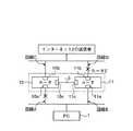
図1は、この発明にかかるVRRPを用いた仮想ルータのシステムにおける実施の形態1の構成を示す構成図である。図において、このシステムでは、図15に示した各ルータ10,11に、回線接続用の物理ポート10a,10b,11a,11bとは別の代替用の物理ポート(以下、「代替用ポート」という)10c,11cを設け、互いの代替用ポート10c,11cを信号線3で接続する構成になっている。これら物理ポートの上位層には図示しないIPアドレスを持つインターフェースである論理ポートが存在しており、この論理ポートの代替用の物理ポートが上記代替用ポートである。なお、物理ポート10a,11aは、マルチキャストの受信者であるPC装置1と接続され、物理ポート10b,11bは、インターネット2のマルチキャストの送信者と接続されている。
【0038】
この実施の形態では、例えば物理ポート10aと11aを有する論理ポートの代替用ポートを、代替用ポート10c,11cとする。この上位層の論理ポートは、論理ポート毎にVRRPのマスタ状態とバックアップ状態が設定されている。この状態設定は、上述したごとく、予め設定された優先度やIPアドレスオーナーであるかなどを基準にしてそれぞれマスタの論理ポートとバックアップの論理ポートが決定されている。物理ポートは、このポートの上位層の論理ポートの状態に依存している。なお、その他の構成は、図15に示した仮想ルータのシステム構成と同じである。以下、同一構成部分には、同一符号を付すものとする。
【0039】
各ルータ10,11は、同一の構成からなり、その一例を図2のブロック図に示す。図2において、ルータ10,11は、回線接続用の物理ポート10a,10b(11a,11b)に繋がる物理インターフェース(以下、「物理I/F」という)20と、代替用ポート10c(11c)と物理I/F20が接続されるレイヤ2のMACフレーム処理部21と、その上位層のレイヤ3のIP処理部22と、VRRP処理部23とから構成されている。
【0040】
MACフレーム処理部21は、図3に示すように、代替用ポート10c(11c)または物理I/F20からのパケットを受信するパケット受信部21aと、代替用ポート10c(11c)または物理I/F20へパケットを送信するパケット送信部21bと、VRRP状態のデータを記憶するVRRP状態テーブル21cと、IP処理部22との間でパケットの入出力を行うIP処理I/F21dとから構成されている。VRRP状態テーブル21cには、例えば各論理ポートに対するマスタ状態またはバックアップ状態を示すデータや優先度を示すデータなどが記憶されている。
【0041】
IP処理部22は、図2に示すように、入力するパケットのIPアドレスから、このパケットがユニキャストパケットか、マルチキャストパケットかを判別して、対応する処理部を選択する処理選択部22aと、ユニキャストパケットのパケット処理を行うユニキャスト処理部22bと、マルチキャストパケットの処理を行うマルチキャスト処理部22cとから構成されている。この処理選択部22aでは、パケットのIPアドレスがマルチキャストグループのグループIPアドレスか、各PC装置に設定された個別のIPアドレスかどうかを判断することで、このパケットがユニキャストパケットかマルチキャストパケットか判断している。
【0042】
マルチキャスト処理部22cは、図4に示すように、入力するマルチキャストパケットの中継制御の処理を行う中継処理部22c1と、マルチキャストパケットをフォワーディングするためのルート情報を格納するマルチキャストフォワーディングテーブル22c2とから構成されている。
【0043】
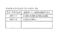
このマルチキャストフォワーディングテーブル22c2は、図5に示すように、たとえば配信されるコンテンツを示すマルチキャストグループのグループIPアドレスと、このグループIPアドレスに対応し、当該マルチキャストグループに参加を希望する各受信者のPC装置が接続されるインターフェースの出力ポート番号と、その出力ポートに設定されているVLANの情報とが対になって格納されている。このマルチキャストフォワーディングテーブル22c2にエントリされている出力ポートとVLANには、代替用ポートに該当する出力ポートと出力VLANもエントリされている。
【0044】
なお、ユニキャスト処理部22bも同様に、図示しない中継処理部とユニキャストフォワーディングテーブルとから構成され、ユニキャストフォワーディングテーブルには、宛先IPアドレスや受信者PC装置に至るネクストホップルータのIPアドレスやこのルータが接続されるインターフェースの出力ポート番号などが格納されている。
【0045】
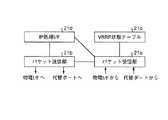
VRRP処理部23は、図6に示すように、IP処理部22からのパケットを受信するVRRPパケット受信部23aと、IP処理部22へパケットを送信するVRRPパケット送信部23bと、VRRP状態を管理するVRRP状態管理部23cと、後述する各タイマのカウント処理を行うタイマ処理部23dとから構成されている。
【0046】
タイマ処理部23dは、図7に示すように、マスタダウンタイマ23d1と、広告タイマ23d2と、マスタ監視タイマ23d3とを有し、これらタイマ23d1〜23d3の所定時間毎のカウント処理を行う。マスタ監視タイマ23d3は、マルチキャスト処理部22cの中継処理部22c1と接続されており、マスタ監視タイマ23d3でのカウントが満了すると、中継処理部22c1は、マルチキャストフォワーディングテーブル22c2の出力ポート、出力VLANのエントリのうち、代替用ポートに該当するエントリを削除することにより、代替用ポートを介したマルチキャストパケットの中継を停止している。
【0047】
VRRP状態管理部23cは、それぞれの論理ポートまたは自ルータがマスタ状態であるかバックアップ状態であるかを管理するとともに、タイマ処理部23dの広告タイマおよびマスタダウンタイマのカウント状態を管理している。
【0048】
このシステムで送受信されるVRRPパケットは、図8に示すように、VRRPプロトコルのバージョン情報を示すバージョンと、VRRPパケットの種類を示すタイプ(ここで、広告パケットは「1」で示されている)と、仮想ルータの識別情報を示すバーチャルルータID(VRID)と、仮想ルータの優先度を示すプライオリティと、この広告パケットに含まれるIPアドレスの数を示すカウントIPアドレス、利用される認証方法を識別するための認証タイプと、広告パケットの送信間隔(通常は1秒)を示す広告インターバルと、チェックサムと、仮想ルータに関連付けられたIPアドレスからなるIPアドレスと、認証を行うための認証データからなる認証データとから構成されている。
【0049】
次に、このような構成におけるルータの動作を図9〜図14のフローチャートに基づいて説明する。ところで、ルータの動作には、大きく分けて3つのイベント、例えばパケット受信、バックアップ状態、マスタ状態のイベントでの動作がある。この実施の形態では、図9〜図12でパケット受信の動作を示し、図13でバックアップ状態からマスタ状態への遷移の動作を示し、図14でマスタ状態の動作を説明する。
【0050】
なお、ルータ10,11におけるマスタルータとバックアップルータの設定は、上述したように、優先度やIPアドレスオーナーなどの基準によって予め決まっており、この例では、上記基準に基づいてルータ10がマスタ状態、ルータ11がバックアップ状態にあるものとする。そして、マスタルータは、タイマ処理部23dのマスタダウンタイマを停止させ、かつ広告タイマをスタートさせるものとする。また、バックアップルータは、タイマ処理部23dの広告タイマを停止させ、かつマスタダウンタイマをスタートさせるものとする。
【0051】
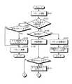
まず、図9において、MACフレーム処理部21のパケット受信部21aは、パケットを受信すると(ステップ101)、VRRP状態テーブル21cを参照して、バックアップ状態でかつ代替用ポートからの入力かどうかを判断する(ステップ102)。
【0052】
ここで、ルータがバックアップ状態でかつ代替用ポートからのパケット受信の場合には、受信したパケットが広告パケットかどうか判断する(ステップ103)。ここで、この受信パケットが広告パケットでない場合には、そのパケットを破棄して動作を終了する(ステップ105)。また、この受信パケットが広告パケットの場合には、相手ルータがマスタ状態で、かつこのVRRPパケットの受信処理が正常に行われていると判断して、マスタ監視タイマ23d3をリスタートし(ステップ104)、ステップ105に進んでこの広告パケットを廃棄する。
【0053】
また、ステップ102において、ルータがバックアップ状態でない場合、または代替用ポートからの受信でない場合には、パケットの宛先アドレスであるMACアドレスを参照して自分宛てかどうか判断する(ステップ106)。
【0054】
ここで、自分宛てでない場合には、このパケットをパケット送信部21bに出力して(ステップ107)、ここでレイヤ2レベルのフォワーディング処理を行い、代替用ポート以外の物理I/Fから物理ポートへ出力する(ステップ108)。また、自分宛ての場合には、IP処理I/F21dを介してIP処理部22へこのパケットを出力し(ステップ109)、このIP処理部22の中継処理部22c1で、上記パケットが広告パケットかどうか、図8に示したパケットのフレーム構成中のタイプから判断する(ステップ110)。
【0055】
なお、このステップ110では、パケットが広告パケットかどうか判断しているが、このパケットが広告パケットの場合とは、たとえば自ルータがマスタ状態で代替用ポートからの広告パケットの場合(以下、「1の場合」という)、自ルータがマスタ状態で物理ポートからの広告パケットの場合(以下、「2の場合」という)、または自ルータがバックアップ状態で物理ポートからの広告パケットの場合(以下、「3の場合」という)が考えられる。
【0056】
ここで、1の場合は、たとえば上述したごとく、経路上の障害復旧時に代替用ポートを介した広告パケットの受信の場合が考えられ、2の場合は、経路上の障害復旧時に物理ポートを介した広告パケットの受信の場合が考えられ、また3の場合は、もっとも一般的なもので、マスタ状態のルータから物理ポートを介した広告パケットの受信の場合が考えられる。これらのうち、1の場合は、代替用ポートに対応して設けられたがマスタ監視タイマ23d3を、中継処理部22c1がリスタートして(ステップ111)、図10に進む。また、2と3の場合には、このステップ111をスルーして図11に進む。
【0057】
ところで、この中継処理部22c1は、図12のフローチャートに示すように、マスタ監視タイマ23d3のカウント値が満了すると(ステップ201)、たとえば相手側のルータがマスタ状態でなくなったか、中継されるデータのトラフィック量が増大して広告パケットの受信処理ができなくない障害状態が発生していると判断して、代替用ポートを介してのマルチキャストの中継を停止する(ステップ202)。
【0058】
すなわち、中継処理部22c1は、マスタ監視タイマ23d3のカウント値が満了すると、マルチキャストフォワーディングテーブル22c2にエントリされている代替用ポートに該当する出力ポートとVLANの情報を削除して、当該代替用ポートへ出力するマルチキャストパケットおよび当該代替用ポートから入力するマルチキャストパケットを廃棄して、広告パケットの受信処理を行えるようにする。
【0059】
なお、代替用ポートを介して入力する広告パケットに対しては、受信の有無のみを監視しており、この広告パケットに応じて、各ルータは、自己の状態(マスタ状態か、バックアップ状態か)を遷移させることは行っていない。すなわち、この状態の遷移は、物理ポートを介して入力する広告パケットに対して、その物理ポート毎に行っているからである。
【0060】
次に、図10のフローチャートについて説明する。まず、図10においては、IP処理部22では、このルータの現在の状態がバックアップ状態かどうか判断し(ステップ112)、バックアップ状態の場合には、マスタダウンタイマをリスタートする(ステップ113)。また、このルータがバックアップ状態でない場合には、マスタルータと判断し(ステップ114)、次にマスタ状態を継続するかどうか判断する(ステップ115)。なお、ここでの判断は、受信した広告パケットの送信元IPアドレス、優先度、自己のIPアドレス、専制モードオンかどうかで判断する。なお、専制モードとは、優先度の低いルータが後からマスタ状態になれるかどうかを示すモードで、オンの場合はそれが可能となることを示している。
【0061】
ここで、マスタ状態を継続する場合には、その状態を維持し(ステップ116)、またマスタ状態をやめてバックアップ状態になった場合には、VRRPパケット受信部23aは、マスタダウンタイマをリスタートさせた後(ステップ117)、広告タイマを停止させる(ステップ118)。
【0062】
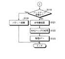
ステップ110において、上記受信したパケットが広告パケットではない場合には、図11に進んで現在の状態がバックアップ状態かどうか判断し(ステップ119)、バックアップ状態の場合には、受信したパケットを破棄する(ステップ120)。また、ルータがバックアップ状態でない場合には、IP処理部22によるレイヤ3レベルのIP中継処理を行った後(ステップ121)、MACフレーム処理部21のパケット送信部21bに出力して、パケット送信部21bによるMACヘッダの処理を行った後に(ステップ122)、物理I/Fへ送信する(ステップ123)。これにより、物理I/Fは、物理ポートを介して回線にパケットを送信することができる。
【0063】
次に、ルータがバックアップ状態からマスタ状態に遷移する場合の動作について図13のフローチャートを用いて説明する。図において、VRRPパケット送信部23bとVRRP状態管理部23cは、タイマ処理部23dのマスタダウンタイマをモニタしている。
【0064】
そして、マスタダウンタイマのカウント値が満了すると(ステップ301)、VRRP状態管理部23cは、もう一方のルータに故障が発生したか回線が断線したと判断して、ルータをマスタ状態に遷移する(ステップ302)。VRRPパケット送信部23bは、広告パケットを作成し、上記広告パケットをVRRPパケット送信部23bからIP処理部22およびMACフレーム処理部21を介して物理I/Fへ送信し、さらに物理I/Fから物理ポートへと送信する(ステップ303)。
【0065】
なお、IP処理部およびMACフレーム処理部21では、それぞれのヘッダの処理を行った後に広告パケットを出力している。
【0066】
次に、VRRPパケット送信部23bは、タイマ処理部23dを制御してマスタダウンタイマを停止させ(ステップ304)、広告タイマをリスタートさせる(ステップ305)。そして、広告タイマのリスタートから所定時間経過してカウントが満了すると(ステップ306)、再びステップ303に戻って、広告パケットを送信する。これにより、物理ポートから回線を介してもう一方のルータに広告パケットが送信される。
【0067】
次に、ルータがマスタ状態にある場合の動作について図14のフローチャートを用いて説明する。図において、VRRPパケット送信部23bは、上述したごとくタイマ処理部23dの広告タイマをモニタしている。
【0068】
そして、VRRPパケット送信部23bは、この広告タイマが満了すると(ステップ401)、広告パケットを作成してIP処理部22およびMACフレーム処理部21を介して物理I/Fへ送信する(ステップ402)。これにより、物理I/Fは、この広告パケットを物理ポートを介して回線に送信することができる。次に、VRRPパケット送信部23bは、広告タイマをリスタートさせ(ステップ403)、カウント値が満了するのを待つ。
【0069】
このような仮想ルータのシステムにおいて、例えば回線AとDが切断された場合、この実施の形態を用いると、ルータ10は、広告パケットを物理ポート10aから回線Aに送信するが、ルータ11には、回線Aの断線のために上記広告パケットは届かない。
【0070】
このため、ルータ11のマスタダウンタイマのカウント値は満了し、ルータ11のVRRP状態管理部23cは、ルータ10に故障が発生したか回線Aが断線したと判断する。この場合、ルータ11には、回線Bを介してPC装置1からパケットが届くので、それによって回線Bが正常であることを確認できる。そこで、VRRP状態管理部23cは、ルータの状態をバックアップ状態からマスタ状態にする。
【0071】
また、ルータ10は、広告パケットを物理ポート10bから回線Cにも送信するが、ルータ11には、回線Dの断線のために上記広告パケットは届かない。このため、ルータ11のマスタダウンタイマのカウント値は満了し、ルータ11のVRRP状態管理部23cは、ルータ10に故障が発生したか回線CかDが断線したと判断する。
【0072】
このように、回線AとDが断線された場合、この実施の形態では、ルータ10,11ともにマスタ状態になり、PC装置1からのパケットは、ルータ11の物理ポート11aから論理ポートに入力し、MACフレーム処理部21、IP処理部22(図2参照)で中継処理がなされた後に、代替用ポート11cを介して信号線3に出力される。
【0073】
そして、信号線3からのパケットは、ルータ10に取り込まれており、ここではスイッチング・リピータ動作が行われるので、パケットは代替用ポート10c、論理ポート、物理ポート10bを通り、回線Cを介してインターネット2へ送信される。
【0074】
また、インターネット2の送信者からのパケットは、回線Cを介してルータ10の物理ポート10bから論理ポートに入力し、MACフレーム処理部21、IP処理部22で中継処理がなされた後に、代替用ポート10cを介して信号線3に出力される。そして、信号線3からのパケットは、ルータ11に取り込まれており、ここではスイッチング・リピータ動作が行われるので、パケットは代替用ポート11c、論理ポート、物理ポート11aを通り、回線Bを介してPC装置1へ送信される。
【0075】
この状態で回線AとDが復旧すると、ルータ10,11はともにマスタ状態になっているので、回線C,Dを介して各ルータ10,11に取り込まれたパケットは、回線A,Bを介してPC装置1に2重化されて出力されることとなる。また、各ルータ10,11は、代替用ポート10c,11cを介して互いのルータに取り込まれることとなる。
【0076】
この時に、このパケットがデータ量が大きいマルチキャストパケットの場合には、代替用ポートを介した広告パケットの受信処理を行えない状態が発生する。各ルータ10,11では、代替用ポートを介した広告パケットの受信が行えなくなると、代替用ポートを介したマルチキャストパケットの中継を停止する。
【0077】
このように、この実施の形態1に示した仮想ルータのシステムでは、仮想ルータを構築する両ルータに物理ポートとは別の代替用ポートを設け、これら代替用ポートを信号線で接続し、回線の断線時にバックアップ状態のルータをマスタ状態に遷移させ、さらにこれら代替用ポートを介した経路でパケットを送信するので、各ルータのそれぞれ1本の回線が切断されても、良好にパケット通信を行うことが可能となり、データ中継の伝送効率を向上させることができる。
【0078】
また、この実施の形態では、障害復旧時に伴い代替用ポートを介した一定時間内の広告パケットの受信が不可能になると、この代替用ポートを介したマルチキャストパケットの送信を停止するので、障害復旧時のデータのトラフィック量の増大を防ぎ、VRRPパケットの受信処理を確実に行い、さらにデータ中継の伝送効率を向上させることができる。
【0079】
また、この実施の形態では、マルチキャストパケットをフォワーディングするために、マルチキャストグループのグループIPアドレスと、このグループIPアドレスに対応し、当該マルチキャストグループに参加を希望する各受信者のPC装置が接続されるインターフェースの出力ポート番号と、その出力ポートに設定されているVLANの情報とをマルチキャストフォワーディングテーブルに格納し、代替用ポートを介した広告パケットの受信が不可能になると、代替用ポートに該当する出力ポートと出力VLANのエントリ情報を削除するので、マルチキャストパケットの送信を確実に停止することができる。
【0080】
さらに、この実施の形態では、マスタ監視タイマでのカウント値が一定時間内の時に、次のVRRPパケットの受信がある場合には、このVRRPパケットの受信処理が正常に行われているので、マスタ監視タイマをリスタートさせるので、代替用ポートを介したパケット中継を継続させることができる。
【0081】
この発明は、これら実施形態に限定されるものではなく、この発明の要旨を逸脱しない範囲で種々の変形実施が可能である。
【0082】
【発明の効果】
以上説明したように、この発明では、物理ポートで送受信されるVRRPパケットとは別に、代替用ポートにもマスタ状態のネットワーク間接続装置からVRRPパケットを定期送信し、通信相手側のネットワーク間接続装置では、このVRRPパケットの受信の有無を監視する機構を設け、代替用ポートを介して、このVRRPパケットが受信できない場合には、この代替用ポートを介したパケットの中継を停止するので、障害からの復旧時にデータのトラフィック量の増大を防ぎ、VRRPパケットの受信処理を確実に行い、データ中継の伝送効率を向上することができる。
【0083】
また、この発明では、代替ポートを介したVRRPのインターバルをカウントし、その間隔が一定時間を超える場合には、相手側がマスタ状態でなくなったか、障害が発生したと判断して、パケットの代替用ポート上への中継を停止するので、VRRPパケットの受信処理を確実に行い、データ中継の伝送効率を向上することができる。
【0084】
また、この発明では、ネットワーク間接続システムに請求項4〜8のいずれか一つに記載の仮想ネットワーク間接続装置を設け、経路上の障害復旧時に代替用ポートを介したVRRPパケットのインターバルが一定時間を超えると、代替用ポートを介したマルチキャストパケットの中継を停止するので、障害からの復旧時にデータのトラフィック量の増大を防ぎ、VRRPパケットの受信処理を確実に行い、データ中継の伝送効率を向上することができる。
【図面の簡単な説明】
【図1】この発明にかかるVRRPを用いた仮想ルータのシステムにおける実施の形態1の構成を示す構成図である。
【図2】図1に示したルータの構成を示すブロック図である。
【図3】図2に示したMACフレーム処理部の構成を示すブロック図である。
【図4】図2に示したマルチキャスト処理部の構成を示すブロック図である。
【図5】図4に示したマルチキャストフォワーディングテーブルの構成の一例を示す構成図である。
【図6】図2に示したVRRP処理部の構成を示すブロック図である。
【図7】図6に示したタイマ処理部の構成を示すブロック図である。
【図8】VRRPパケットのフレーム構成を示す図である。
【図9】図1に示したルータのパケット受信の動作を説明するためのフローチャートである。
【図10】同じく、パケット受信の動作を説明するためのフローチャートである。
【図11】同じく、パケット受信の動作を説明するためのフローチャートである。
【図12】VRRPパケット受信の動作を説明するためのフローチャートである。
【図13】図1に示したルータのバックアップ状態からマスタ状態への遷移の動作を説明するためのフローチャートである。
【図14】図1に示したルータのマスタ状態の動作を説明するためのフローチャートである。
【図15】VRRPを用いた仮想ルータの従来のシステム構成の概念を示す構成図である。
【符号の説明】
1 PC
2 インターネット
3 信号線
10,11 ルータ
10a,10b,11a,11b 物理ポート
10c,11c 代替ポート
20 物理I/F
21 フレーム処理部
21a パケット受信部
21b パケット送信部
21c 状態テーブル
21d IP処理I/F
21e 学習テーブル
22 IP処理部
22a 処理選択部
22b ユニキャスト処理部
22c マルチキャスト処理部
22c1 中継処理部
22c2 マルチキャストフォワーディングテーブル
23 VRRP処理部
23a パケット受信部
23b パケット送信部
23d タイマ処理部
23c 状態管理部
A〜D 回線
Z 仮想ルータ[0001]
TECHNICAL FIELD OF THE INVENTION
The present invention relates to an inter-network connection method using VRRP (Virtual Router Redundancy Protocol: RFC2338) that can ensure redundancy, a virtual inter-network connection device, and an inter-network connection system.
[0002]
[Prior art]
For example, as shown in Non-Patent
[0003]
For such grouped routers, a master router (virtual router) and a backup router are determined on the basis of the priority set by the interface and whether or not the router is an IP address owner, and a VRID (Virtual Router Identifier) is determined. ), An IP address is set for each packet, and only the master router of the corresponding VRID actually performs the packet relay process using the IP address. Note that this IP address is an IP address as a virtual router different from the IP address set in the router itself.
[0004]
The master router notifies the backup router that it is operating normally by periodically transmitting an advertisement packet on the LAN. The backup router confirms that the master router is operating by receiving the advertisement packet, and maintains the standby state while confirming the operation. If the backup router does not receive the advertisement packet within a certain period of time, the backup router determines that an error has occurred in the master router or line, and that a failure has occurred on the route. Relay processing is being performed.
[0005]
FIG. 15 is an example of a configuration diagram showing a concept of a conventional system configuration of a virtual router using VRRP. In the figure, a
[0006]
The
[0007]
Here, for example, when the line A is disconnected, the advertisement packet does not reach the
[0008]
In this conventional example, if the line D is further disconnected from the disconnection state of the line A, the relay operation at the
[0009]
Therefore, there is a configuration in which a substitute physical port (hereinafter, referred to as a “substitute port”) different from the line connection physical port is provided in each router, and the substitute ports are connected by signal lines. (See, for example, Japanese Patent Application No. 2001-376361). A logical port, which is an interface having an IP address (not shown), is present in an upper layer of these physical ports, and a substitute physical port for the logical port is the substitute port.
[0010]
According to the invention of Japanese Patent Application No. 2001-376361, even if one of the lines to which each router is connected is disconnected, the router in the backup state is shifted to the master state when the line is disconnected. A packet is transmitted between the Internet and a PC device by transmitting a packet via a route via an alternative port different from the port.
[0011]
When the disconnection of these lines is recovered, the router that has transitioned to the master state transitions to the backup state again, and the other router in the master state travels through the physical port via a path between the Internet and the PC device. We were relaying.
[0012]
[Non-patent document 1]
Steven Knight, et al., "RFC2338 Virtual Router Redundancy Protocol" [online], April 1998, p. 1-3.6-7.11-13, AlterNIC The Network Center, [Retrieved August 2, 2002], Internet <URL: HYPERLINK "http://alternic.net/rfcs/rfc2300/rfc2338.html">
[0013]
[Problems to be solved by the invention]
However, in the above conventional example, for unicast packet relay, redundant packet relay can be realized by using a virtual router, but in the case of multicast packet relay, appropriate relay may not be performed. There was a problem.
[0014]
That is, when the line is restored, the advertisement packet is normally transmitted from the router in the master state at one-second intervals, so for example, after the line is restored, until the next advertisement packet is transmitted, Routers are also in master state. At this time, when the multicast packet is received by the virtual router, both routers transmit the same multicast packet to the PC device.
[0015]
Such a situation may occur for a unicast packet. In the case of a unicast packet, an entry is generated in the MAC address learning table due to the flow of a packet in the reverse direction. At this point, the duplication of the relay packet is eliminated, and the packet is normally relayed in a relatively short time with a limited transmission time of about several packets. Switch to packet relay. However, in the case of multicast, the data to be relayed is one-way traffic from the sender to the receiver, and since the destination is a multicast address, at the time of recovery, duplicate relay to the normal physical port and alternate port Will be performed. In such a case, the receiving port for the source MAC address learned by each router changes every time a packet is received.
[0016]
Normally, in the learning of the source MAC address for the receiving port, if there is a change in the receiving port, this notification is notified to the host CPU of the router, so that the processing load of the CPU spent on this address learning increases. If this processing load increases every time a multicast packet is relayed, the operation of the CPU is occupied by this processing depending on the state of this processing, and other processing such as VRRP packet reception processing cannot be performed. Things happen. As a result, the VRRP (advertisement) packet receiving process is not performed, one of the routers cannot transition from the master state to the backup state, and the packet relay continues while both routers remain in the VRRP master state. However, there has been a problem that duplication in the distribution of multicast packets continues and the data traffic volume increases. In the current CPU, for example, when data exceeding several Mbps is distributed by multicasting, such a problem may occur.
[0017]
The present invention has been made in view of the above problems, and has an advantage in that a network capable of preventing an increase in data traffic volume at the time of recovery from a failure, reliably performing VRRP packet reception processing, and improving transmission efficiency of data relay. It is an object to provide an internet connection method, a virtual internet connection device, and an internet connection system.
[0018]
[Means for Solving the Problems]
In order to achieve the above object, in the inter-network connection method according to
[0019]
According to the first aspect of the present invention, the VRRP packet is periodically transmitted to the substitute port in addition to the general physical port from the master-network-to-network connecting apparatus. If a large amount of data is transmitted in one direction by multicast or the like, the VRRP packet reception processing is not performed, and if the reception of the VRRP packet cannot be recognized, this replacement is performed after a certain period of time. The relay of the multicast packet via the port for communication is stopped, and the reception process of the VRRP packet is performed.
[0020]
In the inter-network connection method according to
[0021]
According to the second aspect of the present invention, at the time of recovery from a failure on the route, both network connecting devices are in a master state, and a VRRP packet is transmitted from either network connecting device to the other network from the substitute port. The relay of the multicast packet output from the own device to the other-side network connecting device via the substitute port is stopped, and the multicast packet is input from the other side via the substitute port. By stopping the relay of the multicast packet, the receiving process of the VRRP packet is reliably performed, and the transmission efficiency of the data relay is increased.
[0022]
In the inter-network connection method according to
[0023]
According to the third aspect of the present invention, when the interval of the VRRP packet to be transmitted is within a predetermined time, the communication partner is in the master state and there is no increase in the traffic volume of relayed data. Since the reception process is normally performed, the packet relay via the substitute port is continued by restarting the timer means.
[0024]
In addition, in the virtual network connecting apparatus according to claim 4, a plurality of virtual machines are connected in the same network, are set in a relation of master and backup by using VRRP, and have a plurality of substitute ports of interfaces connected to each other. In the virtual network connecting apparatus constructed by the network connecting apparatus and transferring a packet input through the alternative port when a failure occurs on a route, the VRRP packet is transferred between the other networks via the alternative port. Transmitting means for transmitting to the connection device, receiving means for receiving a VRRP packet input through the substitute port, monitoring means for monitoring whether or not the VRRP packet has been received, A relay controller that stops the relay of multicast packets through the port Characterized by comprising and.
[0025]
According to the fourth aspect of the present invention, a mechanism for monitoring a VRRP packet transmitted / received through the substitute port is provided in each inter-network connecting device separately from a VRRP packet transmitted / received through the physical port, and the VRRP packet is received. If unable to do so, stop relaying packets through the alternate port.
[0026]
Further, in the inter-virtual network connection device according to claim 5, the inter-virtual network connection device further includes a timer unit that counts a certain time from the reception of the VRRP packet, and the relay control unit includes a timer unit. The relay of the multicast packet via the substitute port is stopped after a lapse of the counted predetermined time.
[0027]
According to the fifth aspect of the present invention, the interval of the VRRP packet is counted by the timer means, and when the count value exceeds a certain time, the data traffic amount is reduced in the packet relay via the substitute port. Since the failure occurs due to an increase or the other side is no longer in the master state, the relay of the packet to the substitute port is stopped.
[0028]
Further, in the inter-virtual network connection device according to claim 6, the inter-virtual network connection device has at least a group IP address of a multicast group, an output port corresponding to a substitute port, and VLAN information entered. The relay control means, when the count of the timer means expires, deletes the entry corresponding to the substitute port, and stops the relay of the multicast packet via the substitute port. I do.
[0029]
According to the sixth aspect of the present invention, when the count of the timer unit expires, a mechanism corresponding to the substitute port in the entry information of the storage unit is provided as a mechanism for stopping the packet relay to the substitute port by the network connection device. The entry information of the output port and the VLAN to be deleted is deleted, so that the multicast packet cannot be relayed through the substitute port, so that the VRRP packet can be relayed.
[0030]
In the inter-virtual network connection device according to claim 7, the relay control means discards the multicast packet relayed to the substitute port and relays the multicast packet from the substitute port to another physical port. Is discarded, and the packet relay is stopped.
[0031]
According to the present invention, when the relay of the multicast packet is stopped, the packet transmitted to the alternative port and the packet received from the alternative port are discarded to reduce the load on the relay control means.
[0032]
Further, in the virtual network connection apparatus according to claim 8, the relay control means receives the VRRP packet, and receives the next VRRP packet via the substitute port within a predetermined time counted by the timer means. The timer means is restarted upon receipt of the message.
[0033]
According to the invention of claim 8, when the next VRRP packet is received while the count value of the timer means is within a predetermined time, the reception processing of this VRRP packet is normally performed. By restarting the timer means, packet relay via the substitute port is continued.
[0034]
Further, in the network connection system according to the ninth aspect, a virtual network connection device connected to the same network and configured by a plurality of network connection devices set in a relationship of backup with the master using VRRP. A node that transmits a multicast packet to the virtual network connection device, a node that receives the multicast packet transferred from the virtual network connection device, and a transmission line that connects these devices. The virtual network connecting device comprises the virtual network connecting device according to any one of claims 4 to 8, and stops relaying a multicast packet via the substitute port when a failure on a route is recovered. It is characterized by.
[0035]
According to the ninth aspect of the present invention, when the interval of the VRRP packet transmitted from the communication partner exceeds a predetermined time, the communication partner is no longer in the master state, or the traffic volume of relayed data increases. Therefore, by stopping the relay of the multicast packet via the substitute port, an increase in the data traffic volume at the time of recovery from the failure is prevented.
[0036]
BEST MODE FOR CARRYING OUT THE INVENTION
Hereinafter, preferred embodiments of an inter-network connection method, a virtual inter-network connection device, and an inter-network connection system according to the present invention will be described with reference to the accompanying drawings of FIGS.
[0037]
(Embodiment 1)
FIG. 1 is a configuration diagram showing a configuration of a first embodiment in a virtual router system using VRRP according to the present invention. In this system, in this system, each of the
[0038]
In this embodiment, for example, substitute ports of the logical ports having the
[0039]
Each of the
[0040]
As shown in FIG. 3, the MAC
[0041]
As shown in FIG. 2, the
[0042]
As shown in FIG. 4, the
[0043]
As shown in FIG. 5, the multicast forwarding table 22c2 includes, for example, a group IP address of a multicast group indicating contents to be distributed, and a PC of each receiver corresponding to the group IP address and wishing to join the multicast group. The output port number of the interface to which the device is connected and the VLAN information set for the output port are stored as a pair. In the output port and the VLAN entered in the multicast forwarding table 22c2, the output port and the output VLAN corresponding to the substitute port are also entered.
[0044]
Similarly, the
[0045]
As shown in FIG. 6, the
[0046]
As shown in FIG. 7, the
[0047]
The VRRP
[0048]
As shown in FIG. 8, a VRRP packet transmitted / received by this system includes a version indicating version information of the VRRP protocol and a type indicating the type of the VRRP packet (here, the advertisement packet is indicated by “1”). And a virtual router ID (VRID) indicating the identification information of the virtual router, a priority indicating the priority of the virtual router, a count IP address indicating the number of IP addresses included in the advertisement packet, and an authentication method used. Authentication type, an advertisement interval indicating an advertisement packet transmission interval (usually 1 second), a checksum, an IP address including an IP address associated with the virtual router, and authentication data for performing authentication. Authentication data.
[0049]
Next, the operation of the router in such a configuration will be described based on the flowcharts of FIGS. By the way, the operation of the router is roughly divided into three events, for example, an operation of a packet reception, an event of a backup state, and an event of a master state. In this embodiment, the operation of packet reception is shown in FIGS. 9 to 12, the operation of transition from the backup state to the master state is shown in FIG. 13, and the operation of the master state is explained with reference to FIG.
[0050]
As described above, the settings of the master router and the backup router in the
[0051]
First, in FIG. 9, when the
[0052]
If the router is in the backup state and receives a packet from the substitute port, it is determined whether the received packet is an advertisement packet (step 103). Here, if the received packet is not an advertisement packet, the packet is discarded and the operation ends (step 105). If the received packet is an advertisement packet, it is determined that the partner router is in the master state and the reception processing of the VRRP packet is normally performed, and the master monitoring timer 23d3 is restarted (step 104). ), Proceed to step 105, and discard this advertisement packet.
[0053]
If it is determined in
[0054]
If the packet is not addressed to itself, the packet is output to the
[0055]
In step 110, it is determined whether or not the packet is an advertisement packet. The case where the packet is an advertisement packet is, for example, a case where the own router is a master and an advertisement packet from an alternative port (hereinafter, “1”). Case), an advertisement packet from a physical port while the own router is in a master state (hereinafter, referred to as “
[0056]
Here, in the case of 1, for example, as described above, the case of receiving an advertisement packet via the substitute port at the time of restoration of a failure on the route is considered. The case of receiving the advertisement packet described above is considered, and the case of 3 is the most general case, and the case of receiving the advertisement packet from the master router via the physical port is considered. In the case of 1 among these, the relay processing unit 22c1 restarts the master monitoring timer 23d3 provided in correspondence with the substitute port (step 111), and proceeds to FIG. In the case of 2 and 3, the process goes through this
[0057]
By the way, as shown in the flowchart of FIG. 12, when the count value of the master monitoring timer 23d3 expires (step 201), for example, the relay processing unit 22c1 determines whether the partner router is no longer in the master state, It is determined that a failure state has occurred in which the traffic amount has increased and the advertisement packet cannot be received, and the relay of the multicast via the substitute port is stopped (step 202).
[0058]
That is, when the count value of the master monitoring timer 23d3 expires, the relay processing unit 22c1 deletes the output port and VLAN information corresponding to the substitute port entered in the multicast forwarding table 22c2, and sends the information to the substitute port. The output multicast packet and the multicast packet input from the substitute port are discarded so that the advertisement packet can be received.
[0059]
The router monitors only the presence or absence of an advertisement packet input via the substitute port, and according to the advertisement packet, each router determines its own state (master state or backup state). Is not changed. That is, this state transition is performed for each physical port for an advertisement packet input via the physical port.
[0060]
Next, the flowchart of FIG. 10 will be described. First, in FIG. 10, the
[0061]
Here, when the master state is continued, the state is maintained (step 116). When the master state is stopped and the backup state is set, the VRRP
[0062]
In step 110, if the received packet is not an advertisement packet, the process proceeds to FIG. 11 to determine whether the current state is a backup state (step 119). If the packet is in the backup state, the received packet is discarded. (Step 120). When the router is not in the backup state, the
[0063]
Next, the operation when the router transitions from the backup state to the master state will be described using the flowchart of FIG. In the figure, a VRRP
[0064]
When the count value of the master down timer expires (step 301), the VRRP
[0065]
Note that the IP processing unit and the MAC
[0066]
Next, the VRRP
[0067]
Next, the operation when the router is in the master state will be described with reference to the flowchart in FIG. In the figure, the VRRP
[0068]
Then, when the advertisement timer expires (step 401), the VRRP
[0069]
In such a virtual router system, for example, when the lines A and D are disconnected, using this embodiment, the
[0070]
Therefore, the count value of the master down timer of the
[0071]
The
[0072]
As described above, when the lines A and D are disconnected, in this embodiment, both the
[0073]
Then, the packet from the
[0074]
Also, a packet from the sender of the
[0075]
When the lines A and D are restored in this state, since the
[0076]
At this time, if the packet is a multicast packet having a large data amount, a state occurs in which the advertisement packet cannot be received through the substitute port. When each of the
[0077]
As described above, in the virtual router system shown in the first embodiment, both of the routers constituting the virtual router are provided with alternative ports different from the physical ports, and these alternative ports are connected by signal lines, When the router is disconnected, the router in the backup state is transited to the master state, and the packet is transmitted via the route through these substitute ports. Therefore, even if one line of each router is disconnected, the packet communication is performed well. It is possible to improve the transmission efficiency of data relay.
[0078]
Further, in this embodiment, if it becomes impossible to receive the advertisement packet within a certain time via the substitute port at the time of failure recovery, the transmission of the multicast packet via this substitute port is stopped. In this case, it is possible to prevent an increase in the traffic volume of data at the time, reliably perform the reception processing of the VRRP packet, and further improve the transmission efficiency of the data relay.
[0079]
Further, in this embodiment, in order to forward a multicast packet, a group IP address of a multicast group and a PC device of each receiver corresponding to the group IP address and wishing to join the multicast group are connected. The output port number of the interface and the information of the VLAN set to the output port are stored in the multicast forwarding table, and when it becomes impossible to receive the advertisement packet via the substitute port, the output corresponding to the substitute port is output. Since the entry information of the port and the output VLAN is deleted, transmission of the multicast packet can be surely stopped.
[0080]
Further, in this embodiment, when the next VRRP packet is received while the count value of the master monitoring timer is within a predetermined time, the reception processing of this VRRP packet is normally performed. Since the monitoring timer is restarted, packet relay via the substitute port can be continued.
[0081]
The present invention is not limited to these embodiments, and various modifications can be made without departing from the spirit of the present invention.
[0082]
【The invention's effect】
As described above, according to the present invention, apart from the VRRP packet transmitted and received by the physical port, the VRRP packet is periodically transmitted from the master network connection device to the substitute port, and the communication partner network connection device is transmitted. Then, a mechanism for monitoring the presence or absence of the reception of this VRRP packet is provided, and if the VRRP packet cannot be received via the substitute port, the relay of the packet via the substitute port is stopped. In this case, it is possible to prevent the data traffic volume from increasing at the time of recovery from the error, to reliably perform the VRRP packet reception processing, and to improve the transmission efficiency of the data relay.
[0083]
Further, in the present invention, the VRRP interval via the substitute port is counted, and if the interval exceeds a predetermined time, it is determined that the partner side is not in the master state or a failure has occurred, and the packet replacement is performed. Since the relay to the port is stopped, the reception process of the VRRP packet is reliably performed, and the transmission efficiency of the data relay can be improved.
[0084]
In this invention, the network connection system is provided with the virtual network connection device according to any one of claims 4 to 8, and the interval of the VRRP packet via the substitute port at the time of recovery from the failure on the route is constant. If the time is exceeded, the relay of the multicast packet via the substitute port is stopped, so that an increase in the data traffic volume is prevented when recovering from the failure, the VRRP packet receiving process is performed reliably, and the transmission efficiency of the data relay is improved. Can be improved.
[Brief description of the drawings]
FIG. 1 is a configuration diagram showing a configuration of a first embodiment in a virtual router system using VRRP according to the present invention;
FIG. 2 is a block diagram showing a configuration of a router shown in FIG.
FIG. 3 is a block diagram illustrating a configuration of a MAC frame processing unit illustrated in FIG. 2;
FIG. 4 is a block diagram illustrating a configuration of a multicast processing unit illustrated in FIG. 2;
5 is a configuration diagram illustrating an example of a configuration of a multicast forwarding table illustrated in FIG. 4;
FIG. 6 is a block diagram illustrating a configuration of a VRRP processing unit illustrated in FIG. 2;
FIG. 7 is a block diagram illustrating a configuration of a timer processing unit illustrated in FIG. 6;
FIG. 8 is a diagram showing a frame configuration of a VRRP packet.
FIG. 9 is a flowchart for explaining a packet receiving operation of the router shown in FIG. 1;
FIG. 10 is a flowchart for explaining an operation of receiving a packet.
FIG. 11 is a flowchart for explaining an operation of receiving a packet.
FIG. 12 is a flowchart illustrating an operation of receiving a VRRP packet.
FIG. 13 is a flowchart for explaining the operation of the router shown in FIG. 1 to transition from the backup state to the master state;
FIG. 14 is a flowchart illustrating an operation of the router shown in FIG. 1 in a master state.
FIG. 15 is a configuration diagram showing the concept of a conventional system configuration of a virtual router using VRRP.
[Explanation of symbols]
1 PC
2 Internet
3 signal lines
10,11 router
10a, 10b, 11a, 11b physical ports
10c, 11c Alternative port
20 Physical I / F
21 Frame processing unit
21a Packet receiving unit
21b Packet transmission unit
21c status table
21d IP processing I / F
21e Learning table
22 IP processing unit
22a Processing selection unit
22b Unicast processing unit
22c Multicast processing unit
22c1 relay processing unit
22c2 Multicast forwarding table
23 VRRP processing unit
23a packet receiver
23b packet transmitter
23d timer processing unit
23c status management unit
A-D line
Z virtual router
Claims (9)
Translated fromJapanese前記マスタ状態のネットワーク間接続装置は、代替用ポートを介して前記VRRPのパケットを他方のネットワーク間接続装置に送信する送信工程を含み、
前記ネットワーク間接続装置は、前記代替用ポートを介してVRRPパケットを受信する受信工程と、
該VRRPパケットの受信の有無を監視する監視工程と、
該VRRPパケットを受信してから一定時間経過後に、前記代替用ポートを介したマルチキャストパケットの中継を停止する中継制御工程と、
を含むことを特徴とするネットワーク間接続方法。A plurality of inter-network connecting devices construct a virtual inter-network connecting device set in a master-backup relationship by a mounted VRRP, and each of the inter-network connecting devices has a substitute port for an interface connected to each other. And a network connection method for transferring a packet input via the substitute port when a failure occurs on a route,
The master-state network connecting device includes a transmitting step of transmitting the VRRP packet to the other network connecting device via a substitute port,
A receiving step of receiving the VRRP packet via the substitute port,
A monitoring step of monitoring whether or not the VRRP packet has been received;
A relay control step of stopping the relay of the multicast packet via the substitute port after a lapse of a predetermined time after receiving the VRRP packet;
A method for connecting between networks, comprising:
前記代替用ポートを介して前記VRRPのパケットを他方のネットワーク間接続装置に送信する送信手段と、
前記代替用ポートを介して入力するVRRPパケットを受信する受信手段と、
前記VRRPパケットの受信の有無を監視する監視手段と、
前記監視結果に応じて、代替用ポートを介したマルチキャストパケットの中継を停止する中継制御手段と、
を備えたことを特徴とする仮想ネットワーク間接続装置。Connected in the same network, set up in a master-backup relationship using VRRP, and constructed by a plurality of inter-network connecting devices having an alternate port for an interface connected to each other, and In a virtual network connection device that transfers a packet input via an alternative port,
Transmitting means for transmitting the VRRP packet to the other network connection device via the substitute port;
Receiving means for receiving a VRRP packet input via the substitute port;
Monitoring means for monitoring whether or not the VRRP packet has been received;
Relay control means for stopping the relay of the multicast packet via the substitute port according to the monitoring result;
A connection device between virtual networks, comprising:
前記中継制御手段は、前記タイマ手段でカウントされた一定時間経過後に前記代替用ポートを介したマルチキャストパケットの中継を停止することを特徴とする請求項4に記載の仮想ネットワーク間接続装置。The virtual network connection apparatus further includes timer means for counting a fixed time from the reception of the VRRP packet,
The apparatus according to claim 4, wherein the relay control unit stops the relay of the multicast packet via the substitute port after a lapse of a predetermined time counted by the timer unit.
前記中継制御手段は、前記タイマ手段のカウントが満了すると、前記代替用ポートに該当するエントリを削除して、当該代替用ポートを介したマルチキャストパケットの中継を停止することを特徴とする請求項5に記載の仮想ネットワーク間接続装置。The virtual network connection apparatus further includes a storage unit in which at least a group IP address of a multicast group, an output port corresponding to a substitute port, and VLAN information are entered,
6. The relay control unit, when the count of the timer unit expires, deletes an entry corresponding to the substitute port and stops the relay of the multicast packet via the substitute port. The connection device between virtual networks according to 1.
前記仮想ネットワーク間接続装置は、請求項4〜8のいずれか一つに記載の仮想ネットワーク間接続装置からなり、経路上の障害復旧時に前記代替用ポートを介したマルチキャストパケットの中継を停止することを特徴とするネットワーク間接続システム。A virtual network connecting device that is connected in the same network and is constructed by a plurality of network connecting devices that are set in a backup relationship with a master using VRRP, and that transmits a multicast packet to the virtual network connecting device. In a network connection system having a node, a node that receives a multicast packet transferred from the virtual network connection device, and a transmission path that connects these devices,
The virtual network connecting device comprises the virtual network connecting device according to any one of claims 4 to 8, and stops relaying a multicast packet via the substitute port when a failure on a route is recovered. A network connection system characterized by the above-mentioned.
Priority Applications (1)
| Application Number | Priority Date | Filing Date | Title |
|---|---|---|---|
| JP2002236049AJP2004080217A (en) | 2002-08-13 | 2002-08-13 | Network connection method, virtual network connection device, and network connection system |
Applications Claiming Priority (1)
| Application Number | Priority Date | Filing Date | Title |
|---|---|---|---|
| JP2002236049AJP2004080217A (en) | 2002-08-13 | 2002-08-13 | Network connection method, virtual network connection device, and network connection system |
Publications (1)
| Publication Number | Publication Date |
|---|---|
| JP2004080217Atrue JP2004080217A (en) | 2004-03-11 |
Family
ID=32020356
Family Applications (1)
| Application Number | Title | Priority Date | Filing Date |
|---|---|---|---|
| JP2002236049APendingJP2004080217A (en) | 2002-08-13 | 2002-08-13 | Network connection method, virtual network connection device, and network connection system |
Country Status (1)
| Country | Link |
|---|---|
| JP (1) | JP2004080217A (en) |
Cited By (5)
| Publication number | Priority date | Publication date | Assignee | Title |
|---|---|---|---|---|
| JP2004274733A (en)* | 2003-02-20 | 2004-09-30 | Matsushita Electric Ind Co Ltd | Mobile router device, mobile network system, and mobile management method for mobile router device |
| WO2006030623A1 (en)* | 2004-09-16 | 2006-03-23 | Nec Corporation | Method for switching network connecting device using redundant protocol and pseudo-redundant configuring means, and network system |
| WO2008095365A1 (en)* | 2007-02-05 | 2008-08-14 | Huawei Technologies Co., Ltd. | Reliability processing method and system of metro ethernet network which provides multi-service group network |
| US7620366B2 (en) | 2004-07-15 | 2009-11-17 | Samsung Electronics Co., Ltd. | Prefix delegation system and method of ad-hoc network |
| CN102546430A (en)* | 2012-02-05 | 2012-07-04 | 华为技术有限公司 | Method for redundant backup of network equipment, and routing equipment and system |
- 2002
- 2002-08-13JPJP2002236049Apatent/JP2004080217A/enactivePending
Cited By (7)
| Publication number | Priority date | Publication date | Assignee | Title |
|---|---|---|---|---|
| JP2004274733A (en)* | 2003-02-20 | 2004-09-30 | Matsushita Electric Ind Co Ltd | Mobile router device, mobile network system, and mobile management method for mobile router device |
| US7620366B2 (en) | 2004-07-15 | 2009-11-17 | Samsung Electronics Co., Ltd. | Prefix delegation system and method of ad-hoc network |
| WO2006030623A1 (en)* | 2004-09-16 | 2006-03-23 | Nec Corporation | Method for switching network connecting device using redundant protocol and pseudo-redundant configuring means, and network system |
| US7603480B2 (en) | 2004-09-16 | 2009-10-13 | Nec Corporation | System using pseudo redundant configurator to switch network devices between operating and standby states |
| WO2008095365A1 (en)* | 2007-02-05 | 2008-08-14 | Huawei Technologies Co., Ltd. | Reliability processing method and system of metro ethernet network which provides multi-service group network |
| US8320389B2 (en) | 2007-02-05 | 2012-11-27 | Huawei Technologies Co., Ltd. | Reliability processing methods and systems in the networking of metro ethernet network providing multi-service |
| CN102546430A (en)* | 2012-02-05 | 2012-07-04 | 华为技术有限公司 | Method for redundant backup of network equipment, and routing equipment and system |
Similar Documents
| Publication | Publication Date | Title |
|---|---|---|
| JP3956685B2 (en) | Network connection method, virtual network connection device, and network connection system using the device | |
| US7633883B2 (en) | System and method for controlling network traffic | |
| US7355965B2 (en) | Apparatus and method for rapid detection of unidirectional breaks in a network ring | |
| US7339887B2 (en) | Multipoint protected switching ring | |
| JP4370999B2 (en) | Network system, node, node control program, and network control method | |
| JP4449903B2 (en) | Router device and network connection method | |
| CN1969491B (en) | System and method for preserving multicast data forwarding during control failures in a router | |
| EP2245472B1 (en) | System and method for network recovery from multiple link failures | |
| US6928050B2 (en) | Protected switching ring | |
| US8811235B2 (en) | System and method for assuring the operation of network devices in bridged networks | |
| JP4790591B2 (en) | Ring node device | |
| WO2008056838A1 (en) | System and method for controlling network traffic | |
| CN101340380B (en) | Method and apparatus for uninterrupted forwarding of bi-directional forwarding detection in master-slave switch implementation | |
| CN101164307A (en) | Method for service recovery after state switching of main and standby gateway equipment and gateway equipment | |
| WO2009009977A1 (en) | Master backup switch method for route device and backup system for route device | |
| JP2006101471A (en) | Multicast redundant route router, multicast redundancy method | |
| US7974188B2 (en) | Repeater and communication method | |
| WO2012171378A1 (en) | Method and router for preventing flow interruption caused by failover from vpls to l3 | |
| KR101017540B1 (en) | Uninterrupted network control message during local node shutdown | |
| CN102231712B (en) | Method for Load Sharing on Encoder and Encoder | |
| JP2004080217A (en) | Network connection method, virtual network connection device, and network connection system | |
| JP2007228293A (en) | Node device and communication system | |
| US20020089990A1 (en) | Routing system providing continuity of service for the interfaces associated with neighboring networks | |
| JP3773907B2 (en) | Data relay method, data relay device, and data relay system | |
| JP2003244192A (en) | Network connection device redundant configuration method and redundant system |
Legal Events
| Date | Code | Title | Description |
|---|---|---|---|
| A621 | Written request for application examination | Free format text:JAPANESE INTERMEDIATE CODE: A621 Effective date:20050801 | |
| A977 | Report on retrieval | Free format text:JAPANESE INTERMEDIATE CODE: A971007 Effective date:20070510 | |
| A131 | Notification of reasons for refusal | Free format text:JAPANESE INTERMEDIATE CODE: A131 Effective date:20070522 | |
| A02 | Decision of refusal | Free format text:JAPANESE INTERMEDIATE CODE: A02 Effective date:20071106 |