JP2004073812A - Massager - Google Patents
MassagerDownload PDFInfo
- Publication number
- JP2004073812A JP2004073812AJP2002293918AJP2002293918AJP2004073812AJP 2004073812 AJP2004073812 AJP 2004073812AJP 2002293918 AJP2002293918 AJP 2002293918AJP 2002293918 AJP2002293918 AJP 2002293918AJP 2004073812 AJP2004073812 AJP 2004073812A
- Authority
- JP
- Japan
- Prior art keywords
- massage
- head
- affected part
- pressing member
- pressing
- Prior art date
- Legal status (The legal status is an assumption and is not a legal conclusion. Google has not performed a legal analysis and makes no representation as to the accuracy of the status listed.)
- Pending
Links
- 230000007246mechanismEffects0.000claimsabstractdescription28
- 239000012530fluidSubstances0.000claimsdescription10
- 230000006837decompressionEffects0.000claimsdescription3
- 230000000694effectsEffects0.000abstractdescription8
- 230000017531blood circulationEffects0.000description8
- 238000010586diagramMethods0.000description4
- 230000008602contractionEffects0.000description3
- 238000000034methodMethods0.000description3
- 238000007599dischargingMethods0.000description2
- 230000002093peripheral effectEffects0.000description2
- 230000001105regulatory effectEffects0.000description2
- 230000001276controlling effectEffects0.000description1
- 238000005259measurementMethods0.000description1
- 230000004048modificationEffects0.000description1
- 238000012986modificationMethods0.000description1
- 230000000737periodic effectEffects0.000description1
- 230000001737promoting effectEffects0.000description1
- 230000001020rhythmical effectEffects0.000description1
- 239000004065semiconductorSubstances0.000description1
- 230000000087stabilizing effectEffects0.000description1
- 238000007920subcutaneous administrationMethods0.000description1
- 239000002344surface layerSubstances0.000description1
- XLYOFNOQVPJJNP-UHFFFAOYSA-NwaterSubstancesOXLYOFNOQVPJJNP-UHFFFAOYSA-N0.000description1
Images


Landscapes
- Massaging Devices (AREA)
Abstract
Description
Translated fromJapanese【0001】
【発明の属する技術分野】
本発明は、自動でマッサージを行うマッサージ装置に係り、特に吸引式のマッサージと手揉み式のマッサージとを同時に行うマッサージ装置に関するものである。
【0002】
【従来の技術】
吸引式のマッサージと手揉み式のマッサージとを同時に行うマッサージ装置としては、たとえば、特表平10−503397号公報(特許文献1)などがある。
【0003】
【特許文献1】
特表平10−503397号公報
【0004】
このマッサージ装置は、ケーシング内に2つのローラを互いに離間して配置し、これら2つのローラと2つの側壁によって四方側面が形成される減圧される中空部内に、一端が吸引源に接続された導管の他端を開口させてなる。
【0005】
マッサージを行うときは2つのローラに患者のマッサージすべき部位(以下、「患部」と呼ぶ。)を押し当てる。2つのローラはそれぞれ患部を挟み込んで中空部に誘うような向きに回転する動作とその逆転の動作とを交互に繰り返す。これにより患部を断続的につかむような手揉み式のマッサージが実現される。
【0006】
また、この間、中空部のエア吸引による減圧を断続的に行うことで、振動作用による血行促進とともに、皮下や皮肉の脂肪細部を吸引することによる痩身のための吸引式のマッサージが行われるようになっている。
【0007】
【発明が解決しようとする課題】
図11に示すように、かかる従来のマッサージ装置では、患部220の表層部分を引っ張るだけのマッサージとなりがちであり、患部深部のマッサージ感が得られにくい、という問題があった。
【0008】
本発明はこのような課題を解決するためのもので、良好な手揉み感が味わえるとともに、安全性と安定性にも優れたマッサージ装置の提供を目的とする。
【0009】
【課題を解決するための手段】
本発明は、上記の目的を達成するために、一端が開口した中空構造のヘッドと、患部を前記ヘッドの開口部に吸引させるように前記ヘッド内を減圧する減圧機構と、前記開口部に吸引された前記患部を押圧する押圧部材と、前記押圧部材を作動させる駆動機構とを具備するものである。
【0010】
この発明によれば、押圧部材によって患部の深部へ向けての押圧マッサージを行うことができ、手揉みに近い良好なマッサージ感が得られる。
【0011】
また、本発明において、押圧部材は、患部を挟み込む少なくとも一対の挟持部材からなるものとしてもよい。
【0012】
これによれば、あたかも人の指で患部を摘まんでいるかの如く、良好なマッサージ感が得られる。
【0013】
また、本発明は、減圧機構による減圧のオン/オフと、駆動機構による押圧部材の押圧/押圧解除とを連動して行うように制御する制御手段をさらに有するものであってよい。
【0014】
これにより、ヘッドの開口内への患部の吸引と押圧とが同期して行われることになり、リズミカルなマッサージ感が得られる。また、請求項2に記載の一組の挟持部材との併用により、吸引により引っ張りあげた患部を適度な幅で挟み込んで揉みあげることで深いマッサージ感が得られる。
【0015】
さらに、本発明は、駆動機構が、流体の出し入れに伴って膨縮するチューブと、このチューブに流体を出し入れする流体供給機構とを備えるものであってもよい。
【0016】
これにより、吸引と押圧を実現するための制御対象が吸排気系統のみで済み、制御メカニズムが簡単で済む。また、各押圧部材を動作させる機構にチューブを用いたことで、ソフトな押圧が実現されるとともに、安全性を向上させることができる。
【0017】
また、従来のマッサージ装置では、手揉みの動作をローラで実現するためにローラを正転/逆転方向のそれぞれの方向に同じ回転量だけ駆動する必要があったが、この発明のマッサージ装置によれば、チューブ内の流体を自然排出させるだけでも各押圧部材を初期状態に戻すことができる。
【0018】
さらに、この発明において、ヘッドを、少なくとも押圧部材の駆動機構を有する上部ユニットと、この上部ユニットに対して着脱自在で、開口部および押圧部材を有する下部ユニットとで構成すれば、それぞれ形状・サイズの異なる押圧部材を備えた複数の下部ユニットを用意しておくことで、一台のマッサージ装置で多様なマッサージを味わうことが可能になる。
【0019】
【発明の実施の形態】
以下、本発明の実施の形態を図面に基づき詳細に説明する。
【0020】
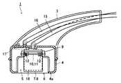
図1はこの発明の第1の実施形態であるマッサージ装置100の全体構成を示す図、図2はこのマッサージ装置100のマッサージ機本体1の平面図、図3はマッサージ機本体1の側面断面図、図4はマッサージ機本体1の正面断面図である。
【0021】
図1に示すように、この第1の実施形態のマッサージ装置100は、マッサージ機本体1とコントローラ2とで構成されている。
【0022】
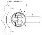
マッサージ機本体1は、利用者によって把持される部分としてのたとえば胴部3を有している。この胴部3の一方の先端には断面が円あるいは多角形のヘッド4が設けられている。このヘッド4は中空部5を有し、このヘッド4の患部が押しあてられる面4aには上記中空部5を露出する患部吸引部としての開口6が設けられている。
【0023】
中空部5には、患部を押圧する部材として、一対の挟持形押圧部材7,8が配設されている。ヘッド4の内部にはベース部9が設けられており、このベース部9には2本の枢支軸10,11が互いに平行な向きで固定されている。そして各枢支軸10,11にはそれぞれ、対応する一つの挟持形押圧部材7,8が回動自在に支持されている。
【0024】
コントローラ2は、給排気装置19と、ユーザインタフェースとして利用者からの操作入力を受け付ける操作入力部13と、操作入力部13より入力された指示に基づいて給排気装置19を制御する制御部14とで構成されている。
【0025】
給排気装置19は、独立した2つの吸排気系である第1の吸排気系および第2の吸排気系を備えており、各々個別に流体の吸引と排出との切り替え、吸排気量、給排気時間などの制御を行うことが可能とされている。
【0026】
第1の吸排気系は、ヘッド4の開口6が患部で塞がれることによって閉じられた中空部5内を断続的に減圧するように、可撓性を有する配管15を通じて当該中空部5の給排気を交互に切り替えて行う系である。これによりヘッド4の開口6に患部が断続的に吸引され(吸引とその解除が交互に行われ)、吸引式のマッサージが行われるようになっている。
【0027】
第2の吸排気系は、マッサージ機本体1のヘッド4内に組み込まれているエアチューブ17に対して、可撓性を有する別の配管16を通じて流体の出し入れを時間的に交互に切り替えて行う系であり、これによってエアチューブ17の膨張と収縮との繰り返しを実現するものである。
【0028】
図4に示したように、エアチューブ17はヘッド4の内壁と各挟持形押圧部材7,8との間に配設されている。エアチューブ17の両端部には、個々の挟持形押圧部材7,8に作用する部分としての押圧作用部18,18がそれぞれ設けられている。そしてこれら押圧作用部18,18の膨張/収縮に伴って各挟持形押圧部材7,8がそれぞれ枢支軸10,11を支点に回動するようになっている。
図5ないし図8に挟持形押圧部材7,8の回動の様子を示す。
【0029】
このように、エアチューブ17の押圧作用部18,18の膨張/収縮に伴って、各挟持形押圧部材7,8の患部挟持部分である先端部どうしの距離がL1からL3までの範囲で可変する。このとき各挟持形押圧部材7,8の先端部で患部を断続的に挟持することによって手揉み式のマッサージが行われる。
【0030】
なお、枢支軸10,11にはコイルバネ12が取り付けられており、エアチューブ17の収縮サイクル時に、各押圧部材7,8は上記コイルバネ12の弾性力によって互いの先端どうしが離間する方向へ回動する。これにより各挟持形押圧部材7,8を初期の位置に確実に復帰させることができる。
【0031】
操作入力部13には、主電源、マッサージの開始/終了、各種パラメータ設定のためのスイッチ・ボタンが設けられている。設定可能なパラメータには、マッサージの時間、強さ、周期などがある。
【0032】
制御部14は、この操作入力部13を用いて利用者より与えられた指示や設定パラメータに基づいて、給排気装置19の上記2つの吸排気系の制御を行う。
【0033】
次に、この第1の実施形態であるマッサージ装置100の動作を説明する。
【0034】
利用者はコントローラ2の操作入力部で、マッサージの時間、強さ、周期などを設定する。
【0035】
ヘッド4の先端の開口6に患部を押しあて、コントローラ2のマッサージ開始ボタンを押す。すると制御部14がこれを認識してマッサージの動作を開始する。
【0036】
図5から図8に、この第1の実施形態のマッサージ装置100の一連の動作を示す。
【0037】
図5はヘッド4の先端の開口6に患部を押しあてたときの初期状態を示している。
【0038】
この状態から第1の吸排気系を吸引作動するとともに、第2の吸排気系を排気作動する。すると、図6に示すように、第1の吸排気系の吸引作動よりヘッド4の開口6に押しあてられていた患部20が吸引される。このときの吸引力は第1の吸排気系の吸引量の制御により可変することができる。
【0039】
一方、第2の吸排気系の排気作動によりエアチューブ17への流体供給が開始され、エアチューブ17の両側の押圧作用部18,18が徐々に膨らみ、それぞれの挟持形押圧部材7,8を背後から押圧する。これにより、各挟持形押圧部材7,8が枢支軸10,11を支点に互いに接近する方向つまりAの矢印方向にコイルバネ12の弾性力に逆らって回動し、図7に示すように、ベース部9の側面9aによって規制を受けるまで回動する。これら挟持形押圧部材7,8の回動によって、ヘッド4の開口6に吸引された患部20が各挟持形押圧部材7,8によって両側から挟み込まれたかたちで押圧される。
【0040】
この後、第1の吸排気系を排気作動するとともに、第2の吸排気系を吸引作動する。すると図8に示すように、第1の吸排気系の排気作動よりヘッド4の開口6に患部20を吸引させる力が解除されるとともに、第2の吸排気系の吸気作動によりエアチューブ17からの流体排出が開始され、エアチューブ17の両側の押圧作用部18,18が徐々に収縮する。その結果、各挟持形押圧部材7,8はコイルバネ12による付勢力に助けられながら、互いに離間する方向つまりBの矢印方向に回動し、患部20の押圧を徐々に解除して行き、図5に示す初期状態に復帰する。
【0041】
以上が、1サイクルのマッサージの動きであり、この後、再び第1の吸排気系の吸引と第2の吸排気系の排気が行われ、上述した動作が繰り返される。
【0042】
このようにして吸引式のマッサージと手揉み式のマッサージとが同時に行われる。
【0043】
このマッサージ装置100の特徴は吸引マッサージと手揉みマッサージとが同時に行われることはさることながら、一対の挟持形押圧部材7,8によって患部を両側より挟み込むようにして手揉み式のマッサージを行えるので、旧来のローラによるマッサージに比べ、患部深部に向けてマッサージの負荷を加えることができ、良好なマッサージ効果を期待できる。
【0044】
また、このマッサージ装置100によれば、吸引によって引き上げられた患部20を各挟持形押圧部材7,8で揉みあげるので、患部20を適度な幅で確実に挟み込んで揉みあげることが可能である。すなわち、患部20を吸引によって引き上げずに各挟持形押圧部材7,8で揉みあげようとすると、ヘッド4の開口6への患部20の押し当てが不十分であった場合などに、挟持形押圧部材7,8で患部20を十分な幅で挟み込めなかったり、最悪の場合は空振りし、安定しない。これに対し、このマッサージ装置100によれば、誰もが一定のマッサージを受けられるようになる。
【0045】
さらに、この実施形態のマッサージ装置100は、制御対象が給排気装置19の2つの吸排気系のみであり、制御メカニズムが簡単で済む。
【0046】
すなわち、一対の挟持形押圧部材7,8を動作させる機構としては、エアチューブ17に対してエアを出し入れする方法の他に、電動機を用いたメカニカル機構も考えられるが、この場合、制御対象が構造的に全く異なった2つの機構となり、それだけ全体の制御も複雑になるが、この実施形態のマッサージ装置100によりその問題を解消できる。
【0047】
また、一対の挟持形押圧部材7,8を動作させる機構にエアチューブ17を用いたことで、ソフトな押圧が実現されるとともに、安全性を向上させることができる。
【0048】
また、従来のマッサージ装置では、手揉みの動作をローラで実現するためにローラを正転/逆転方向のそれぞれの方向に同じ回転量だけ駆動する必要があったが、この実施形態のマッサージ装置100では、エアチューブ17内の流体を自然排出させるだけでも一対の挟持形押圧部材7,8を初期状態に戻すことができる。
【0049】
この実施形態のマッサージ装置100では、図9に示すように、挟持形押圧部材7,8を一組用いたが、たとえば、図9に示すように、より広い範囲を同時にマッサージできるように、複数の対の挟持形押圧部材7a,7b,8a,8bを直線上に複数並設するようにしてもよい。
【0050】
次に、本発明に係るマッサージ装置の第2の実施形態を説明する。
【0051】
図12および図13に、この第2の実施形態であるマッサージ装置101の構成を示す。
【0052】
これらの図に示すように、このマッサージ装置101は、利用者によって把持される部分としての胴部23を有している。この胴部23の一方の先端には矩形状のヘッド24が設けられている。このヘッド24は中空部25を有し、このヘッド24の患部が押しあてられる面24aには上記中空部25を露出する患部吸引部としての開口26が設けられている。
【0053】
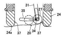
中空部25には、患部を押圧する部材である単一のローラ形押圧部材27が配設されている。このローラ形押圧部材27は、胴部23の上部に軸受28と作動ギア29の軸受穴とによって両端が保持された枢支軸30に揺動アーム31を介して揺動自在に支承されている。駆動ギア29にはモータ32の駆動ギア33と連結されており、モータ32の駆動、たとえば周期的な正転/逆転駆動の繰り返しによって、ローラ形押圧部材27は枢支軸30を支点として振り子運動をするようになっている。
【0054】
さらに、ローラ形押圧部材27の両側面には係合ピン34,34がそれぞれ突設されており、これらの係合ピン34,34はヘッド24内に固定された図示しないカムプレートに形成されたカム穴35に挿入、保持されている。モータ32の駆動によってローラ形押圧部材27が作動すると、ローラ形押圧部材27の両側面の各係合ピン34,34がカム穴35に沿って移動する。このことによって、ローラ形押圧部材27を一定の軌跡で振り子運動させることが可能になり、動作が安定する。
【0055】
図14ないし図16に、このマッサージ装置101によるマッサージの様子を示す。
【0056】
このようにモータ32の駆動によりローラ形押圧部材27が振り子運動をする。このときローラ形押圧部材27とその移動方向の先のヘッド内壁面37との間で患部20を挟み込むことによって、断続的な手揉み式のマッサージが行われる。
【0057】
また、このマッサージ装置101には、ヘッド24の開口26が患部で塞がれることによって閉じられた中空部25内を断続的に減圧するように、可撓性を有する配管36を通じて当該中空部25の給排気を交互に切り替えて行う吸排気系が設けられている。これによりヘッド24の開口26に患部が断続的に吸引され(吸引とその解除が交互に行われ)、吸引式のマッサージが行われるようになっている。
【0058】
このようにして吸引式のマッサージと手揉み式のマッサージとが同時に行われる。
【0059】
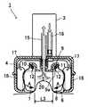
次に、本発明に係る第3の実施形態であるマッサージ装置について図17ないし図19を参照して説明する。
【0060】
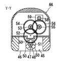
図17ないし図19は、それぞれ本実施形態のマッサージ装置におけるヘッド44の部分の構成を示した断面図および平面図である。したがって、利用者によって把持される胴部などは省略してある。
【0061】
このヘッド44は、中空部45を有し、このヘッド44の患部が押しあてられる面44aには上記中空部45を露出する患部吸引部としての開口46が設けられている。なお、図ではヘッド44の断面を円形としているが、四角形などの多角形状であってもよい。
【0062】
中空部45には、患部を押圧する部材である複数の回転形押圧部材47が配設されている。これらの回転形押圧部材47は、それぞれ定位置で同時に回転し得るように、一本の軸48を介して同軸的に連結されている。軸48の両端はヘッド44内に固定された軸受49にて回転自在に支持されている。個々の回転形押圧部材47には、一定の回転角ピッチで押圧用の突起50が複数(この例では3つ)設けられている。そして、これらの突起50は、各回転形押圧部材47の間で押圧タイミングが互いにずれるように、各回転形押圧部材47を軸48に固定する際のそれぞれの回転角度位置が選定されている。
【0063】
各回転形押圧部材47が固定された軸48の一端にはギア51が同軸に固定されており、このギア51には、ギア群52−56を介してモータ59のドライブギア58と連結されており、モータ59の駆動力で各回転形押圧部材47が正逆両方向に回転し得るようになっている。
【0064】
回転形押圧部材47の回転方向はスイッチ操作で選択できるようにしてもよく、さらには、一定時間の周期で正逆両方向に交互に回転させるモードを設けてもよい。
【0065】
また、このマッサージ装置には、ヘッド44の開口46が患部で塞がれることによって閉じられた中空部45内を断続的に減圧するように、可撓性を有する配管60を通じて当該中空部45の給排気を交互に切り替えて行う吸排気系が設けられている。これによりヘッド44の開口46への患部の吸引とその解除が交互に行われるようになっている。
【0066】
そして、患部が吸引されているとき、回転する各回転形押圧部材47の突起50が吸引されている患部を押圧することで、手揉み感覚に近いマッサージが実現される。
【0067】
本実施形態のマッサージ装置と従来のローラ式マッサージ装置(図11)によるマッサージ効果(血流増加度)を比較した結果を図32に示す。血流増加度とは、マッサージ前後で皮膚の赤みがどのくらい増加したかを測定した結果であり、マッサージ前の値を100としている。測定方法には、レーザードップラー法を用い、半導体レーザーとして波長670nmのレーザーを用いた。
【0068】
本実施形態のマッサージ装置によりモード1−3の条件でマッサージを実施し、使用直後、5分後、10分後のそれぞれの血流増加度を測定した。ここで、モード1は1秒毎に回転方向を正逆切り替えるモード、モード2は5秒毎に回転方向を正逆切り替えるモード、モード3は一定の回転方向に連続駆動させるモードである。同様に、従来のローラ式マッサージ装置によりマッサージを実施し、使用直後、5分後、10分後のそれぞれの血流増加度を測定した。
【0069】
それぞれの血流増加度の測定結果を比較検討してみたところ、本実施形態のマッサージ装置は、従来のローラ式マッサージよりも高いマッサージ効果が得られることを確認できた。特に、回転方向を交互に切り替えてマッサージを行うことによって、より優れた血行促進効果が得られることを確認した。
【0070】
次に、本発明のマッサージ装置に係る第4の実施形態を図20を用いて説明する。
【0071】
同図に示すように、この実施形態は、ヘッド61において、患部を押圧する複数の突起62を軸63の周面に直接設けたものである。これらの突起62は軸63の周面に一定の回転角ピッチで設けられ、軸63に沿った方向にて隣り合う突起62どうしは互いに押圧タイミングがずれるように配設されている。
【0072】
その他の構成は前記第3の実施形態と同様のため説明を省略する。
【0073】
次に、本発明のマッサージ装置に係る第5の実施形態を図21を用いて説明する。
【0074】
この実施形態のマッサージ装置は、前記第3の実施形態と同様に、一定の回転角ピッチで押圧用の突起50がそれぞれ設けられた複数(この例では3つ)の回転形押圧部材47A,47B,47Cを備える。
【0075】
第3の実施形態と異なる点は、3つの回転形押圧部材47A,47B,47Cを2つのグループに分け、各グループ間で回転方向を逆にした点にある。その具体的な実現手段として、2本の軸65,66を用いる。一方の軸65を円筒状とし、この円筒内にもう一方の軸66を回転自在な状態で配置する。各々の軸65,66の一端部にはギア67,68が同軸的に固定され、それぞれのギア67,68に図示しないモータの駆動力が個別に伝達されることによって、各々の軸65,66が互いに逆方向に回転する。
【0076】
これにより一方の軸65に固定された2つの回転形押圧部材47A,47Cと、他方の軸66に固定された1つの回転形押圧部材47Bとが互いに逆方向に回転し、患部に捻りを加えたマッサージが実現される。
【0077】
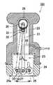
次に、本発明のマッサージ装置に係る第6の実施形態を図22および図23を用いて説明する。
【0078】
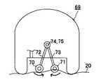
この実施形態のマッサージ装置のヘッド69は、患部を押圧する部材として2つのローラ形押圧部材70,71を備えている。各ローラ形押圧部材70,71は、それぞれ別々の揺動アーム72,73の一端に設けられている。各揺動アーム72,73の他端は、互いに独立して軸受76により回転自在に支持された2本の軸74,75の側面にそれぞれ個別に固定されている。各々の軸74,75の一端部にはギア77がそれぞれ固定されており、これらのギア77に図示しない駆動モータからの駆動力が個別に伝達されるようになっている。
【0079】
2本の軸74,75は、互いに同期しながら反対の方向に、一定の回転角の範囲を往復して回動するように駆動される。これにより、各ローラ形押圧部材70,71が互いに同期しつつ逆方向に振り子運動をすることによって、患部に捻りを加えたマッサージが実現される。
【0080】
次に、本発明のマッサージ装置に係る第7の実施形態を図24を用いて説明する。
【0081】
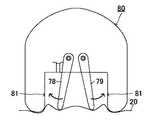
本実施形態は、第1の実施形態のマッサージ装置100の変形である。第1の実施形態のマッサージ装置100では、一対の挟持形押圧部材7,8が互いに接近するように回動して一対の挟持形押圧部材7,8の間で患部を挟み込んでマッサージを行うものであったが、第7の実施形態では、一対の挟持形押圧部材78,79が互いに離間するように回動し、それぞれの挟持形押圧部材78,79とヘッド80の内壁81との間で患部を挟み込んでマッサージを行うようにしたものである。
【0082】
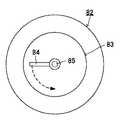
次に、本発明のマッサージ装置に係る第8の実施形態を図25および図26を用いて説明する。
【0083】
この実施形態のマッサージ装置は、ヘッド82の開口83に吸引された患部20を、押圧部材84を上から撫でるようにして押圧するものである。押圧部材84は開口83の面に対して垂直に設けられた回転軸85の先端に固定されており、回転軸85を図示しない駆動機構により回転させることで、押圧部材84が旋回するように構成されている。
【0084】
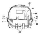
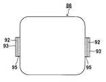
次に、本発明のマッサージ装置に係る第9の実施形態を図27ないし図30を用いて説明する。
【0085】
この実施形態は、マッサージ装置のヘッド86において、押圧部材87を交換できるように、押圧部材87を含むヘッド下部ユニット88を、この押圧部材87の駆動機構90や吸引機構(図示せず)を含むヘッド上部ユニット89に対して着脱自在にしたものである。
【0086】
たとえば、ヘッド下部ユニット88とヘッド上部ユニット89の両サイドにはリブ91,92が突出して設けられており、これらのリブ91,92を上下重ね合わせ、固定具93で上下から挟み込んで結合することで、ヘッド下部ユニット88とヘッド上部ユニット89とが両側2ヶ所でロックされるようになっている。
【0087】
リブ91,92には、固定具93のスライド方向を規制する溝状のレール部94,95がそれぞれ設けられており、固定具93は上下重ね合わせられた各リブ91,92の溝状のレール部94,95に従ってマニュアル操作でスライドさせることによって、ロックのための取り付けとアンロックのための取り外しが簡単に行えるようになっている。
【0088】
このように、ヘッド下部ユニット88とヘッド上部ユニット89との着脱を可能にしたことで、図31に示すように、ヘッド下部ユニット88として、サイズ、形状といった条件が異なる押圧部材87A,87Bを組み込んだ複数のユニット88A,88Bをあらかじめ用意しておき、これらを選択的に用いることで、様々な場所、目的のマッサージを一台の装置で行えるようになる。
なお、図31に示すように、一方の着脱自在なヘッド下部ユニット88Aの押圧部材87Aはヘッド先端より一部が突出しており、押圧力が他方の着脱自在なヘッド下部ユニット88Bより大きく、より高いマッサージ効果が得られる。
【0089】
また、ヘッド下部ユニット88をヘッド上部ユニット89から分離できることで、ヘッド下部ユニット88の水洗いが可能になる。このため、オイルを皮膚に塗ってマッサージを行った後、ヘッド下部ユニット88に付着したオイルをきれいに洗い流すことができる。
【0090】
【発明の効果】
以上、説明したように本発明のマッサージ装置によれば、押圧部材によって患部を両側より挟み込むようにして手揉み式のマッサージを行えるので、旧来のローラによるマッサージに比べ、患部深部に向けてマッサージの負荷を加えることができ、良好なマッサージ効果を期待できる。また、ヘッドの開口に吸引された患部を各押圧部材で揉みあげることができ、患部を適度な幅で確実に挟み込んで揉みあげることが可能になる。さらに、吸引式と手揉み式の各マッサージを実現するための制御対象が吸排気系統のみで済み、制御メカニズムが簡単で済む。また、各押圧部材を動作させる機構にチューブを用いたことで、ソフトな押圧が実現されるとともに、安全性を向上させることができる。
【図面の簡単な説明】
【図1】この発明の第1の実施形態であるマッサージ装置の全体構成を示す図である。
【図2】図1のマッサージ装置のマッサージ機本体の平面図である。
【図3】図2のマッサージ機本体の側面断面図である。
【図4】図2のマッサージ機本体の正面断面図である。
【図5】図2のマッサージ機本体のヘッドの開口に患部を押しあてたときの初期状態を示す正面断面図である。
【図6】ヘッド開口への患部吸引と各押圧部材による患部挟み込みの開始状態を示す正面断面図である。
【図7】各押圧部材による患部挟み込みが完了した状態を示す正面断面図である。
【図8】ヘッド開口への患部吸引と各押圧部材による患部挟み込みを解除した状態を示す正面断面図である。
【図9】図2のマッサージ機本体のヘッドの斜視図である。
【図10】第1の実施形態のヘッドの変形例を示す斜視図である。
【図11】従来のローラを用いたマッサージの課題を説明するための図である。
【図12】本発明の第2の実施形態である一つの押圧部材を用いたマッサージ装置の構成を示す正面断面図である。
【図13】図12のマッサージ装置をヘッドの開口側から見た平面図である。
【図14】このマッサージ装置による手揉み式のマッサージの動作の初期状態を示す図である。
【図15】同じくこのマッサージ装置による手揉み式のマッサージの動作を示す図である。
【図16】同じくこのマッサージ装置による手揉み式のマッサージの動作を示す図である。
【図17】本発明の第3の実施形態であるマッサージ装置のヘッドの縦断面図である。
【図18】図17のヘッドの別の断面図である。
【図19】図17のヘッドの開口側の平面図である。
【図20】本発明の第4の実施形態であるマッサージ装置のヘッドの縦断面図である。
【図21】本発明の第5の実施形態であるマッサージ装置のヘッドの縦断面図である。
【図22】本発明の第6の実施形態であるマッサージ装置のヘッドの縦断面図である。
【図23】図22のヘッドの別の断面図である。
【図24】本発明の第7の実施形態であるマッサージ装置のヘッドの縦断面図である。
【図25】本発明の第8の実施形態であるマッサージ装置のヘッドの縦断面図である。
【図26】図25のヘッドの開口側の平面図である。
【図27】本発明の第9の実施形態であるマッサージ装置のヘッドの縦断面図である。
【図28】図27のヘッドの分解した断面図である。
【図29】図27のヘッドを上部ユニット側から見た平面図である。
【図30】図27のヘッドの上下ユニットを分離する際の固定具の取り外しの様子を示す平面図である。
【図31】ヘッド下部ユニットの交換を示す図である。
【図32】本実施形態と従来の各マッサージ装置によるマッサージ効果(血流増加度)を比較した結果を示す図表である。
【符号の説明】
1・・・・マッサージ機本体
2・・・・コントローラ
3,23・・・・胴部
4,24・・・・ヘッド
5,25・・・中空部
6,26・・・・開口
7,8,27・・・・押圧部材
10,11・・・・枢支軸
12・・・・コイルバネ
13・・・・操作入力部
14・・・・制御部
15,16・・・・配管
17・・・・エアチューブ
18・・・・押圧作用部
19・・・・吸排気装置
20・・・・患部
28・・・・軸受
29・・・・作動ギア
30・・・・枢支軸
31・・・・揺動アーム
32・・・・モータ
33・・・・駆動ギア
34・・・・係合ピン
35・・・・カム穴
37・・・・ヘッド内壁面
100,101・・・・マッサージ装置[0001]
TECHNICAL FIELD OF THE INVENTION
The present invention relates to a massage device for performing automatic massage, and more particularly to a massage device for simultaneously performing suction-type massage and hand-massage type massage.
[0002]
[Prior art]
As a massage device that simultaneously performs a suction-type massage and a hand-massage type massage, there is, for example, Japanese Patent Application Laid-Open No. 10-503397 (Patent Document 1).
[0003]
[Patent Document 1]
Japanese Unexamined Patent Publication No. Hei 10-503397
[0004]
In this massage device, two rollers are arranged apart from each other in a casing, and a conduit having one end connected to a suction source is provided in a depressurized hollow portion formed by the two rollers and two side walls on four sides. Is opened at the other end.
[0005]
When performing massage, a part to be massaged by a patient (hereinafter, referred to as “affected part”) is pressed against two rollers. The two rollers alternately repeat the operation of rotating in the direction of sandwiching the affected part and inviting it to the hollow part, and the reverse operation. This realizes a hand-massage type massage in which the affected area is intermittently grasped.
[0006]
Also, during this time, by performing intermittent decompression by air suction in the hollow part, blood circulation is promoted by vibratory action, and suction-type massage for slimming by sucking subcutaneous and ironic fat details is performed. Has become.
[0007]
[Problems to be solved by the invention]
As shown in FIG. 11, such a conventional massage device tends to be a massage that only pulls the surface layer of the affected
[0008]
The present invention is intended to solve such a problem, and an object of the present invention is to provide a massage device that can have a good hand-rubbing feeling and is excellent in safety and stability.
[0009]
[Means for Solving the Problems]
In order to achieve the above object, the present invention provides a head having a hollow structure with one end opened, a decompression mechanism for depressurizing the inside of the head so that an affected part is sucked into the opening of the head, and suction to the opening. And a driving mechanism for operating the pressing member.
[0010]
According to the present invention, the pressing member can perform the pressing massage toward the deep part of the affected part, and a good massage feeling close to hand massage can be obtained.
[0011]
In the present invention, the pressing member may include at least a pair of holding members that sandwich the affected part.
[0012]
According to this, a good massage feeling can be obtained as if the affected part were pinched with the finger of a person.
[0013]
Further, the present invention may further include a control unit that controls the on / off of the pressure reduction by the pressure reduction mechanism and the pressing / release of the pressing member by the driving mechanism in an interlocked manner.
[0014]
As a result, suction and pressing of the affected part into the opening of the head are performed in synchronization with each other, and a rhythmic massage feeling can be obtained. In addition, by using in combination with the pair of holding members described in claim 2, a deep massage feeling can be obtained by nipping and rubbing the affected part pulled by suction with an appropriate width.
[0015]
Further, in the present invention, the drive mechanism may include a tube that expands and contracts as fluid flows in and out, and a fluid supply mechanism that moves fluid in and out of the tube.
[0016]
Thus, only the intake / exhaust system needs to be controlled to realize suction and pressing, and the control mechanism is simple. Further, by using a tube for the mechanism for operating each pressing member, soft pressing can be realized and safety can be improved.
[0017]
Further, in the conventional massage device, it was necessary to drive the roller by the same amount of rotation in each of the forward rotation direction and the reverse rotation direction in order to realize the operation of hand massage with the roller. In this case, each pressing member can be returned to the initial state only by spontaneously discharging the fluid in the tube.
[0018]
Further, according to the present invention, if the head is composed of an upper unit having at least a driving mechanism for the pressing member and a lower unit detachably mountable to the upper unit and having an opening and a pressing member, the shape and the size are each By preparing a plurality of lower units provided with different pressing members, it is possible to enjoy various massages with one massage device.
[0019]
BEST MODE FOR CARRYING OUT THE INVENTION
Hereinafter, embodiments of the present invention will be described in detail with reference to the drawings.
[0020]
FIG. 1 is a view showing an overall configuration of a
[0021]
As shown in FIG. 1, the
[0022]
The massage machine
[0023]
The
[0024]
The controller 2 includes an air supply /
[0025]
The supply /
[0026]
The first air intake / exhaust system is provided with a
[0027]
The second intake / exhaust system alternately switches fluid in and out of the
[0028]
As shown in FIG. 4, the
FIGS. 5 to 8 show how the
[0029]
As described above, with the expansion / contraction of the
[0030]
A
[0031]
The
[0032]
The
[0033]
Next, the operation of the
[0034]
The user sets the massage time, intensity, cycle, and the like using the operation input unit of the controller 2.
[0035]
The affected part is pressed against the
[0036]
5 to 8 show a series of operations of the
[0037]
FIG. 5 shows an initial state when the affected part is pressed against the
[0038]
From this state, the first intake / exhaust system is operated to perform suction, and the second intake / exhaust system is operated to exhaust. Then, as shown in FIG. 6, the
[0039]
On the other hand, the supply of fluid to the
[0040]
Thereafter, the first intake / exhaust system is evacuated, and the second intake / exhaust system is evacuated. Then, as shown in FIG. 8, the force for sucking the
[0041]
The above is one cycle of the massage operation. After that, the suction of the first intake and exhaust system and the exhaust of the second intake and exhaust system are performed again, and the above-described operation is repeated.
[0042]
In this way, the suction massage and the hand massage are performed simultaneously.
[0043]
The feature of the
[0044]
Further, according to the
[0045]
Furthermore, the
[0046]
That is, as a mechanism for operating the pair of sandwiching-
[0047]
Further, by using the
[0048]
Further, in the conventional massage device, it is necessary to drive the roller by the same amount of rotation in each of the forward rotation direction and the reverse rotation direction in order to realize the operation of the hand massage by the roller. Then, the pair of sandwiching
[0049]
In the
[0050]
Next, a second embodiment of the massage device according to the present invention will be described.
[0051]
12 and 13 show the configuration of a
[0052]
As shown in these figures, the
[0053]
In the
[0054]
Further, engagement pins 34, 34 are provided on both side surfaces of the roller-
[0055]
14 to 16 show a state of massage by the
[0056]
Thus, the roller-
[0057]
In addition, the
[0058]
In this way, the suction massage and the hand massage are performed simultaneously.
[0059]
Next, a massage device according to a third embodiment of the present invention will be described with reference to FIGS.
[0060]
17 to 19 are a cross-sectional view and a plan view, respectively, showing the configuration of the
[0061]
The
[0062]
The
[0063]
A
[0064]
The rotation direction of the
[0065]
Further, in this massage device, the
[0066]
When the affected part is being sucked, the
[0067]
FIG. 32 shows the result of comparing the massage effect (the degree of increase in blood flow) between the massage device of this embodiment and the conventional roller massage device (FIG. 11). The degree of increase in blood flow is a result of measuring how much redness of the skin has increased before and after massage, and the value before massage is set to 100. A laser Doppler method was used as a measuring method, and a laser having a wavelength of 670 nm was used as a semiconductor laser.
[0068]
Massage was performed under the conditions of mode 1-3 by the massage device of the present embodiment, and the blood flow increase was measured 5 minutes and 10 minutes immediately after use. Here,
[0069]
Comparing the measurement results of the degree of increase in blood flow with each other, it was confirmed that the massage device of the present embodiment can obtain a higher massage effect than the conventional roller massage. In particular, it was confirmed that a more excellent blood circulation promoting effect was obtained by performing the massage by alternately switching the rotation direction.
[0070]
Next, a fourth embodiment according to the massage device of the present invention will be described with reference to FIG.
[0071]
As shown in the figure, in this embodiment, in a
[0072]
The other configuration is the same as that of the third embodiment, and the description is omitted.
[0073]
Next, a fifth embodiment according to the massage device of the present invention will be described with reference to FIG.
[0074]
As in the third embodiment, the massage device of this embodiment has a plurality (three in this example) of rotary press members 47A and 47B provided with
[0075]
The difference from the third embodiment is that the three rotary pressing members 47A, 47B, and 47C are divided into two groups, and the rotation direction is reversed between the groups. Two shafts 65 and 66 are used as a specific realizing means. One of the shafts 65 has a cylindrical shape, and the other shaft 66 is rotatably disposed in the cylinder.
[0076]
As a result, the two rotary pressing members 47A and 47C fixed to one shaft 65 and the one rotary pressing member 47B fixed to the other shaft 66 rotate in directions opposite to each other, and twist the affected part. Massage is realized.
[0077]
Next, a sixth embodiment according to the massage device of the present invention will be described with reference to FIGS.
[0078]
The
[0079]
The two
[0080]
Next, a seventh embodiment according to the massage device of the present invention will be described with reference to FIG.
[0081]
The present embodiment is a modification of the
[0082]
Next, an eighth embodiment according to the massage apparatus of the present invention will be described with reference to FIGS.
[0083]
The massage device of this embodiment presses the
[0084]
Next, a ninth embodiment of the massage device of the present invention will be described with reference to FIGS.
[0085]
In this embodiment, the head
[0086]
For example,
[0087]
The
[0088]
Since the head
As shown in FIG. 31, the pressing
[0089]
Further, since the head
[0090]
【The invention's effect】
As described above, according to the massage device of the present invention, the hand massage can be performed by sandwiching the affected part from both sides by the pressing member. A load can be added and a good massage effect can be expected. In addition, the affected part sucked into the opening of the head can be rubbed with each pressing member, and the affected part can be securely sandwiched with an appropriate width and rubbed. Furthermore, only the intake / exhaust system needs to be controlled to realize the suction type massage and the hand massage type massage, and the control mechanism is simple. Further, by using a tube for the mechanism for operating each pressing member, soft pressing can be realized and safety can be improved.
[Brief description of the drawings]
FIG. 1 is a diagram showing an overall configuration of a massage device according to a first embodiment of the present invention.
FIG. 2 is a plan view of a massage machine main body of the massage device of FIG. 1;
FIG. 3 is a side sectional view of the massage machine main body of FIG. 2;
FIG. 4 is a front sectional view of the massage machine main body of FIG. 2;
5 is a front sectional view showing an initial state when the affected part is pressed against the opening of the head of the massage machine main body of FIG. 2;
FIG. 6 is a front sectional view showing a state in which the affected part is sucked into the head opening and the affected part is sandwiched between the pressing members.
FIG. 7 is a front sectional view showing a state in which the sandwiching of the affected part by each pressing member is completed.
FIG. 8 is a front sectional view showing a state in which the suction of the affected part into the head opening and the pinching of the affected part by each pressing member are released.
FIG. 9 is a perspective view of a head of the massage machine main body of FIG. 2;
FIG. 10 is a perspective view showing a modified example of the head of the first embodiment.
FIG. 11 is a diagram for explaining a problem of massage using a conventional roller.
FIG. 12 is a front cross-sectional view illustrating a configuration of a massage device using one pressing member according to a second embodiment of the present invention.
FIG. 13 is a plan view of the massage device of FIG. 12 as viewed from the opening side of the head.
FIG. 14 is a diagram showing an initial state of a hand-massage type massage operation by this massage device.
FIG. 15 is a view showing an operation of a hand-massage type massage by the massage device.
FIG. 16 is a view showing the operation of massaging by hand using the massage device.
FIG. 17 is a longitudinal sectional view of a head of a massage device according to a third embodiment of the present invention.
FIG. 18 is another sectional view of the head of FIG. 17;
19 is a plan view of the head of FIG. 17 on the opening side.
FIG. 20 is a longitudinal sectional view of a head of a massage device according to a fourth embodiment of the present invention.
FIG. 21 is a longitudinal sectional view of a head of a massage device according to a fifth embodiment of the present invention.
FIG. 22 is a longitudinal sectional view of a head of a massage device according to a sixth embodiment of the present invention.
FIG. 23 is another sectional view of the head of FIG. 22;
FIG. 24 is a longitudinal sectional view of a head of a massage device according to a seventh embodiment of the present invention.
FIG. 25 is a longitudinal sectional view of a head of a massage device according to an eighth embodiment of the present invention.
26 is a plan view of the head of FIG. 25 on the opening side.
FIG. 27 is a longitudinal sectional view of a head of a massage device according to a ninth embodiment of the present invention.
FIG. 28 is an exploded sectional view of the head of FIG. 27;
FIG. 29 is a plan view of the head of FIG. 27 as viewed from the upper unit side.
30 is a plan view showing a state of removing a fixing tool when separating the upper and lower units of the head in FIG. 27;
FIG. 31 is a diagram showing replacement of a head lower unit.
FIG. 32 is a table showing the results of comparing the massage effect (the degree of increase in blood flow) between the present embodiment and conventional massage devices.
[Explanation of symbols]
1. The body of the massage machine
2. Controller
3,23 ... torso
4, 24 ... head
5, 25 ... hollow part
... opening
7, 8, 27 ... Pressing member
······· 11
12 ... Coil spring
13. Operation input unit
14 Control unit
15,16 ... Piping
17. Air tube
18 ... Pressing action part
19 ··· Intake and exhaust device
20 ... affected area
28 ... Bearing
29 ・ ・ ・ ・ ・ ・ Operating gear
30 ... Pivot shaft
31 ... Swing arm
32 Motor
33 Drive gear
34 ··· Engagement pin
35 ... Cam hole
37 ··· Head inner wall surface
100, 101 ... massage device
Claims (5)
Translated fromJapanese患部を前記ヘッドの開口部に吸引させるように前記ヘッド内を減圧する減圧機構と、
前記開口部に吸引された前記患部を押圧する押圧部材と、
前記押圧部材を作動させる駆動機構と
を具備することを特徴とするマッサージ装置。A hollow structure head with one end open,
A decompression mechanism that decompresses the inside of the head so that the affected part is sucked into the opening of the head,
A pressing member that presses the affected part sucked into the opening,
A massage mechanism comprising a drive mechanism for operating the pressing member.
Priority Applications (1)
| Application Number | Priority Date | Filing Date | Title |
|---|---|---|---|
| JP2002293918AJP2004073812A (en) | 2002-06-20 | 2002-10-07 | Massager |
Applications Claiming Priority (2)
| Application Number | Priority Date | Filing Date | Title |
|---|---|---|---|
| JP2002180589 | 2002-06-20 | ||
| JP2002293918AJP2004073812A (en) | 2002-06-20 | 2002-10-07 | Massager |
Publications (1)
| Publication Number | Publication Date |
|---|---|
| JP2004073812Atrue JP2004073812A (en) | 2004-03-11 |
Family
ID=32032577
Family Applications (1)
| Application Number | Title | Priority Date | Filing Date |
|---|---|---|---|
| JP2002293918APendingJP2004073812A (en) | 2002-06-20 | 2002-10-07 | Massager |
Country Status (1)
| Country | Link |
|---|---|
| JP (1) | JP2004073812A (en) |
Cited By (37)
| Publication number | Priority date | Publication date | Assignee | Title |
|---|---|---|---|---|
| WO2006038277A1 (en)* | 2004-10-04 | 2006-04-13 | Numax Co., Ltd. | Suction massaging unit |
| WO2010094888A1 (en)* | 2009-02-20 | 2010-08-26 | Daniel Frajdenrajch | Suction massage device for forming several folds with composite folding |
| KR20120062717A (en)* | 2009-08-20 | 2012-06-14 | 시네론 메디컬 리미티드 | Method and apparatus for non-invasive aesthetic treatment of skin and sub-dermis |
| US8285390B2 (en) | 2007-08-21 | 2012-10-09 | Zeltiq Aesthetics, Inc. | Monitoring the cooling of subcutaneous lipid-rich cells, such as the cooling of adipose tissue |
| CN102805703A (en)* | 2011-05-30 | 2012-12-05 | 安得士股份有限公司 | Massage mechanism and massage device having the same |
| US8337539B2 (en) | 2006-02-22 | 2012-12-25 | Zeltiq Aesthetics, Inc. | Cooling device for removing heat from subcutaneous lipid-rich cells |
| US8523927B2 (en) | 2007-07-13 | 2013-09-03 | Zeltiq Aesthetics, Inc. | System for treating lipid-rich regions |
| US8603073B2 (en) | 2008-12-17 | 2013-12-10 | Zeltiq Aesthetics, Inc. | Systems and methods with interrupt/resume capabilities for treating subcutaneous lipid-rich cells |
| US8676338B2 (en) | 2010-07-20 | 2014-03-18 | Zeltiq Aesthetics, Inc. | Combined modality treatment systems, methods and apparatus for body contouring applications |
| US8702774B2 (en) | 2009-04-30 | 2014-04-22 | Zeltiq Aesthetics, Inc. | Device, system and method of removing heat from subcutaneous lipid-rich cells |
| US9132031B2 (en) | 2006-09-26 | 2015-09-15 | Zeltiq Aesthetics, Inc. | Cooling device having a plurality of controllable cooling elements to provide a predetermined cooling profile |
| US9545523B2 (en) | 2013-03-14 | 2017-01-17 | Zeltiq Aesthetics, Inc. | Multi-modality treatment systems, methods and apparatus for altering subcutaneous lipid-rich tissue |
| USD777338S1 (en) | 2014-03-20 | 2017-01-24 | Zeltiq Aesthetics, Inc. | Cryotherapy applicator for cooling tissue |
| CN106456436A (en)* | 2014-06-06 | 2017-02-22 | Lpg系统公司 | Massage head and massage apparatus using such a head |
| JP2017516525A (en)* | 2014-06-06 | 2017-06-22 | エルページュ・システムズ | Massage head and massage device using the massage head |
| US9844460B2 (en) | 2013-03-14 | 2017-12-19 | Zeltiq Aesthetics, Inc. | Treatment systems with fluid mixing systems and fluid-cooled applicators and methods of using the same |
| US9844461B2 (en) | 2010-01-25 | 2017-12-19 | Zeltiq Aesthetics, Inc. | Home-use applicators for non-invasively removing heat from subcutaneous lipid-rich cells via phase change coolants |
| US9861421B2 (en) | 2014-01-31 | 2018-01-09 | Zeltiq Aesthetics, Inc. | Compositions, treatment systems and methods for improved cooling of lipid-rich tissue |
| US10383787B2 (en) | 2007-05-18 | 2019-08-20 | Zeltiq Aesthetics, Inc. | Treatment apparatus for removing heat from subcutaneous lipid-rich cells and massaging tissue |
| US10524956B2 (en) | 2016-01-07 | 2020-01-07 | Zeltiq Aesthetics, Inc. | Temperature-dependent adhesion between applicator and skin during cooling of tissue |
| US10555831B2 (en) | 2016-05-10 | 2020-02-11 | Zeltiq Aesthetics, Inc. | Hydrogel substances and methods of cryotherapy |
| US10568759B2 (en) | 2014-08-19 | 2020-02-25 | Zeltiq Aesthetics, Inc. | Treatment systems, small volume applicators, and methods for treating submental tissue |
| US10675176B1 (en) | 2014-03-19 | 2020-06-09 | Zeltiq Aesthetics, Inc. | Treatment systems, devices, and methods for cooling targeted tissue |
| US10682297B2 (en) | 2016-05-10 | 2020-06-16 | Zeltiq Aesthetics, Inc. | Liposomes, emulsions, and methods for cryotherapy |
| US10722395B2 (en) | 2011-01-25 | 2020-07-28 | Zeltiq Aesthetics, Inc. | Devices, application systems and methods with localized heat flux zones for removing heat from subcutaneous lipid-rich cells |
| US10765552B2 (en) | 2016-02-18 | 2020-09-08 | Zeltiq Aesthetics, Inc. | Cooling cup applicators with contoured heads and liner assemblies |
| US10935174B2 (en) | 2014-08-19 | 2021-03-02 | Zeltiq Aesthetics, Inc. | Stress relief couplings for cryotherapy apparatuses |
| US10952891B1 (en) | 2014-05-13 | 2021-03-23 | Zeltiq Aesthetics, Inc. | Treatment systems with adjustable gap applicators and methods for cooling tissue |
| US11076879B2 (en) | 2017-04-26 | 2021-08-03 | Zeltiq Aesthetics, Inc. | Shallow surface cryotherapy applicators and related technology |
| US11154418B2 (en) | 2015-10-19 | 2021-10-26 | Zeltiq Aesthetics, Inc. | Vascular treatment systems, cooling devices, and methods for cooling vascular structures |
| US11382790B2 (en) | 2016-05-10 | 2022-07-12 | Zeltiq Aesthetics, Inc. | Skin freezing systems for treating acne and skin conditions |
| US11395760B2 (en) | 2006-09-26 | 2022-07-26 | Zeltiq Aesthetics, Inc. | Tissue treatment methods |
| WO2022180868A1 (en)* | 2021-02-26 | 2022-09-01 | 株式会社ユニッシュ | Facial ligament/facial fascia release device |
| US11446175B2 (en) | 2018-07-31 | 2022-09-20 | Zeltiq Aesthetics, Inc. | Methods, devices, and systems for improving skin characteristics |
| FR3121840A1 (en)* | 2021-04-20 | 2022-10-21 | Lpg Systems | Massage head and massage device |
| US11986421B2 (en) | 2006-09-26 | 2024-05-21 | Zeltiq Aesthetics, Inc. | Cooling devices with flexible sensors |
| US12070411B2 (en) | 2006-04-28 | 2024-08-27 | Zeltiq Aesthetics, Inc. | Cryoprotectant for use with a treatment device for improved cooling of subcutaneous lipid-rich cells |
- 2002
- 2002-10-07JPJP2002293918Apatent/JP2004073812A/enactivePending
Cited By (66)
| Publication number | Priority date | Publication date | Assignee | Title |
|---|---|---|---|---|
| WO2006038277A1 (en)* | 2004-10-04 | 2006-04-13 | Numax Co., Ltd. | Suction massaging unit |
| US8337539B2 (en) | 2006-02-22 | 2012-12-25 | Zeltiq Aesthetics, Inc. | Cooling device for removing heat from subcutaneous lipid-rich cells |
| US12070411B2 (en) | 2006-04-28 | 2024-08-27 | Zeltiq Aesthetics, Inc. | Cryoprotectant for use with a treatment device for improved cooling of subcutaneous lipid-rich cells |
| US11395760B2 (en) | 2006-09-26 | 2022-07-26 | Zeltiq Aesthetics, Inc. | Tissue treatment methods |
| US11219549B2 (en) | 2006-09-26 | 2022-01-11 | Zeltiq Aesthetics, Inc. | Cooling device having a plurality of controllable cooling elements to provide a predetermined cooling profile |
| US11986421B2 (en) | 2006-09-26 | 2024-05-21 | Zeltiq Aesthetics, Inc. | Cooling devices with flexible sensors |
| US10292859B2 (en) | 2006-09-26 | 2019-05-21 | Zeltiq Aesthetics, Inc. | Cooling device having a plurality of controllable cooling elements to provide a predetermined cooling profile |
| US11179269B2 (en) | 2006-09-26 | 2021-11-23 | Zeltiq Aesthetics, Inc. | Cooling device having a plurality of controllable cooling elements to provide a predetermined cooling profile |
| US9375345B2 (en) | 2006-09-26 | 2016-06-28 | Zeltiq Aesthetics, Inc. | Cooling device having a plurality of controllable cooling elements to provide a predetermined cooling profile |
| US9132031B2 (en) | 2006-09-26 | 2015-09-15 | Zeltiq Aesthetics, Inc. | Cooling device having a plurality of controllable cooling elements to provide a predetermined cooling profile |
| US10383787B2 (en) | 2007-05-18 | 2019-08-20 | Zeltiq Aesthetics, Inc. | Treatment apparatus for removing heat from subcutaneous lipid-rich cells and massaging tissue |
| US11291606B2 (en) | 2007-05-18 | 2022-04-05 | Zeltiq Aesthetics, Inc. | Treatment apparatus for removing heat from subcutaneous lipid-rich cells and massaging tissue |
| US8523927B2 (en) | 2007-07-13 | 2013-09-03 | Zeltiq Aesthetics, Inc. | System for treating lipid-rich regions |
| US9655770B2 (en) | 2007-07-13 | 2017-05-23 | Zeltiq Aesthetics, Inc. | System for treating lipid-rich regions |
| US10675178B2 (en) | 2007-08-21 | 2020-06-09 | Zeltiq Aesthetics, Inc. | Monitoring the cooling of subcutaneous lipid-rich cells, such as the cooling of adipose tissue |
| US9408745B2 (en) | 2007-08-21 | 2016-08-09 | Zeltiq Aesthetics, Inc. | Monitoring the cooling of subcutaneous lipid-rich cells, such as the cooling of adipose tissue |
| US8285390B2 (en) | 2007-08-21 | 2012-10-09 | Zeltiq Aesthetics, Inc. | Monitoring the cooling of subcutaneous lipid-rich cells, such as the cooling of adipose tissue |
| US11583438B1 (en) | 2007-08-21 | 2023-02-21 | Zeltiq Aesthetics, Inc. | Monitoring the cooling of subcutaneous lipid-rich cells, such as the cooling of adipose tissue |
| US8603073B2 (en) | 2008-12-17 | 2013-12-10 | Zeltiq Aesthetics, Inc. | Systems and methods with interrupt/resume capabilities for treating subcutaneous lipid-rich cells |
| US9737434B2 (en) | 2008-12-17 | 2017-08-22 | Zeltiq Aestehtics, Inc. | Systems and methods with interrupt/resume capabilities for treating subcutaneous lipid-rich cells |
| WO2010094888A1 (en)* | 2009-02-20 | 2010-08-26 | Daniel Frajdenrajch | Suction massage device for forming several folds with composite folding |
| FR2942397A1 (en)* | 2009-02-20 | 2010-08-27 | Daniel Frajdenrajch | DEVICE FOR MASSAGE BY LOW PRESSURE FORMING MULTIPLE PLY COMPOSITE PLASTS |
| US11224536B2 (en) | 2009-04-30 | 2022-01-18 | Zeltiq Aesthetics, Inc. | Device, system and method of removing heat from subcutaneous lipid-rich cells |
| US9861520B2 (en) | 2009-04-30 | 2018-01-09 | Zeltiq Aesthetics, Inc. | Device, system and method of removing heat from subcutaneous lipid-rich cells |
| US11452634B2 (en) | 2009-04-30 | 2022-09-27 | Zeltiq Aesthetics, Inc. | Device, system and method of removing heat from subcutaneous lipid-rich cells |
| US8702774B2 (en) | 2009-04-30 | 2014-04-22 | Zeltiq Aesthetics, Inc. | Device, system and method of removing heat from subcutaneous lipid-rich cells |
| KR101687854B1 (en) | 2009-08-20 | 2016-12-19 | 시네론 메디컬 리미티드 | Method and apparatus for non-invasive aesthetic treatment of skin and sub-dermis |
| KR20120062717A (en)* | 2009-08-20 | 2012-06-14 | 시네론 메디컬 리미티드 | Method and apparatus for non-invasive aesthetic treatment of skin and sub-dermis |
| JP2013502264A (en)* | 2009-08-20 | 2013-01-24 | シネロン メディカル リミテッド | Method and apparatus for non-invasive aesthetic treatment of skin and lower skin |
| US9844461B2 (en) | 2010-01-25 | 2017-12-19 | Zeltiq Aesthetics, Inc. | Home-use applicators for non-invasively removing heat from subcutaneous lipid-rich cells via phase change coolants |
| US10092346B2 (en) | 2010-07-20 | 2018-10-09 | Zeltiq Aesthetics, Inc. | Combined modality treatment systems, methods and apparatus for body contouring applications |
| US8676338B2 (en) | 2010-07-20 | 2014-03-18 | Zeltiq Aesthetics, Inc. | Combined modality treatment systems, methods and apparatus for body contouring applications |
| US10722395B2 (en) | 2011-01-25 | 2020-07-28 | Zeltiq Aesthetics, Inc. | Devices, application systems and methods with localized heat flux zones for removing heat from subcutaneous lipid-rich cells |
| CN102805703B (en)* | 2011-05-30 | 2014-04-30 | 安得士股份有限公司 | Massage mechanism and massage device having the same |
| CN102805703A (en)* | 2011-05-30 | 2012-12-05 | 安得士股份有限公司 | Massage mechanism and massage device having the same |
| US9844460B2 (en) | 2013-03-14 | 2017-12-19 | Zeltiq Aesthetics, Inc. | Treatment systems with fluid mixing systems and fluid-cooled applicators and methods of using the same |
| US9545523B2 (en) | 2013-03-14 | 2017-01-17 | Zeltiq Aesthetics, Inc. | Multi-modality treatment systems, methods and apparatus for altering subcutaneous lipid-rich tissue |
| US10575890B2 (en) | 2014-01-31 | 2020-03-03 | Zeltiq Aesthetics, Inc. | Treatment systems and methods for affecting glands and other targeted structures |
| US11819257B2 (en) | 2014-01-31 | 2023-11-21 | Zeltiq Aesthetics, Inc. | Compositions, treatment systems and methods for improved cooling of lipid-rich tissue |
| US10201380B2 (en) | 2014-01-31 | 2019-02-12 | Zeltiq Aesthetics, Inc. | Treatment systems, methods, and apparatuses for improving the appearance of skin and providing other treatments |
| US10806500B2 (en) | 2014-01-31 | 2020-10-20 | Zeltiq Aesthetics, Inc. | Treatment systems, methods, and apparatuses for improving the appearance of skin and providing other treatments |
| US10912599B2 (en) | 2014-01-31 | 2021-02-09 | Zeltiq Aesthetics, Inc. | Compositions, treatment systems and methods for improved cooling of lipid-rich tissue |
| US9861421B2 (en) | 2014-01-31 | 2018-01-09 | Zeltiq Aesthetics, Inc. | Compositions, treatment systems and methods for improved cooling of lipid-rich tissue |
| US10675176B1 (en) | 2014-03-19 | 2020-06-09 | Zeltiq Aesthetics, Inc. | Treatment systems, devices, and methods for cooling targeted tissue |
| USD777338S1 (en) | 2014-03-20 | 2017-01-24 | Zeltiq Aesthetics, Inc. | Cryotherapy applicator for cooling tissue |
| US10952891B1 (en) | 2014-05-13 | 2021-03-23 | Zeltiq Aesthetics, Inc. | Treatment systems with adjustable gap applicators and methods for cooling tissue |
| CN106456436A (en)* | 2014-06-06 | 2017-02-22 | Lpg系统公司 | Massage head and massage apparatus using such a head |
| JP2017516525A (en)* | 2014-06-06 | 2017-06-22 | エルページュ・システムズ | Massage head and massage device using the massage head |
| JP2017516524A (en)* | 2014-06-06 | 2017-06-22 | エルページュ・システムズ | Massage head and massage device using the massage head |
| US10935174B2 (en) | 2014-08-19 | 2021-03-02 | Zeltiq Aesthetics, Inc. | Stress relief couplings for cryotherapy apparatuses |
| US10568759B2 (en) | 2014-08-19 | 2020-02-25 | Zeltiq Aesthetics, Inc. | Treatment systems, small volume applicators, and methods for treating submental tissue |
| US11154418B2 (en) | 2015-10-19 | 2021-10-26 | Zeltiq Aesthetics, Inc. | Vascular treatment systems, cooling devices, and methods for cooling vascular structures |
| US10524956B2 (en) | 2016-01-07 | 2020-01-07 | Zeltiq Aesthetics, Inc. | Temperature-dependent adhesion between applicator and skin during cooling of tissue |
| US10765552B2 (en) | 2016-02-18 | 2020-09-08 | Zeltiq Aesthetics, Inc. | Cooling cup applicators with contoured heads and liner assemblies |
| US11382790B2 (en) | 2016-05-10 | 2022-07-12 | Zeltiq Aesthetics, Inc. | Skin freezing systems for treating acne and skin conditions |
| US10682297B2 (en) | 2016-05-10 | 2020-06-16 | Zeltiq Aesthetics, Inc. | Liposomes, emulsions, and methods for cryotherapy |
| US10555831B2 (en) | 2016-05-10 | 2020-02-11 | Zeltiq Aesthetics, Inc. | Hydrogel substances and methods of cryotherapy |
| US11076879B2 (en) | 2017-04-26 | 2021-08-03 | Zeltiq Aesthetics, Inc. | Shallow surface cryotherapy applicators and related technology |
| US11446175B2 (en) | 2018-07-31 | 2022-09-20 | Zeltiq Aesthetics, Inc. | Methods, devices, and systems for improving skin characteristics |
| US12102557B2 (en) | 2018-07-31 | 2024-10-01 | Zeltiq Aesthetics, Inc. | Methods, devices, and systems for improving skin characteristics |
| CN115916134A (en)* | 2021-02-26 | 2023-04-04 | 尤奈思股份有限公司 | Facial ligament and facial fascia release instrument |
| US11872178B2 (en) | 2021-02-26 | 2024-01-16 | Unish Inc. | Facial ligament/facial fascia release device |
| JP2022131533A (en)* | 2021-02-26 | 2022-09-07 | 株式会社ユニッシュ | Facial ligament/facial fascia release device |
| WO2022180868A1 (en)* | 2021-02-26 | 2022-09-01 | 株式会社ユニッシュ | Facial ligament/facial fascia release device |
| EP4079277A1 (en)* | 2021-04-20 | 2022-10-26 | Lpg Systems | Massage head and massage device |
| FR3121840A1 (en)* | 2021-04-20 | 2022-10-21 | Lpg Systems | Massage head and massage device |
Similar Documents
| Publication | Publication Date | Title |
|---|---|---|
| JP2004073812A (en) | Massager | |
| KR100231146B1 (en) | Chair massage | |
| JP3087864U (en) | Massage equipment | |
| JP5079888B2 (en) | Cervical massage device | |
| CN106473911B (en) | A kind of Orthopaedic nursing massage recovering apparatus | |
| CN103816033A (en) | Eyelid massager | |
| CN107260507A (en) | Control method of massage machine and treatment member of massage machine | |
| JP2000325416A (en) | Massage machine | |
| CN202497417U (en) | Hand imitation head massaging device | |
| JP2000262575A (en) | Massage device | |
| JP3165140B2 (en) | Massage machine | |
| CN208626119U (en) | Cam Chiropractic Bed | |
| JP2007215555A (en) | Massaging machine | |
| JP6562617B2 (en) | Massage equipment | |
| JP2002238967A (en) | Massaging unit | |
| CN210494556U (en) | Massage mechanism and massage control device and massager thereof | |
| KR100948934B1 (en) | Hand massage | |
| CN200945231Y (en) | Finger kneading massager | |
| CN203815850U (en) | Eyelid-massaging spectacles | |
| WO2022185816A1 (en) | Massager | |
| CN114366587A (en) | A medical neck massage device | |
| CN203315296U (en) | Massage device for assisting self-recovery of tenosynovitis | |
| JP5215795B2 (en) | Massage equipment | |
| JP2004358277A (en) | Massager machine | |
| CN103330638A (en) | Massage device for assisting tenosynovitis self-cure and use method thereof |
Legal Events
| Date | Code | Title | Description |
|---|---|---|---|
| A621 | Written request for application examination | Free format text:JAPANESE INTERMEDIATE CODE: A621 Effective date:20050914 | |
| A977 | Report on retrieval | Free format text:JAPANESE INTERMEDIATE CODE: A971007 Effective date:20080111 | |
| A131 | Notification of reasons for refusal | Free format text:JAPANESE INTERMEDIATE CODE: A131 Effective date:20080122 | |
| A02 | Decision of refusal | Free format text:JAPANESE INTERMEDIATE CODE: A02 Effective date:20080610 |