JP2004061713A - Closure for optical cable connection - Google Patents
Closure for optical cable connectionDownload PDFInfo
- Publication number
- JP2004061713A JP2004061713AJP2002217997AJP2002217997AJP2004061713AJP 2004061713 AJP2004061713 AJP 2004061713AJP 2002217997 AJP2002217997 AJP 2002217997AJP 2002217997 AJP2002217997 AJP 2002217997AJP 2004061713 AJP2004061713 AJP 2004061713A
- Authority
- JP
- Japan
- Prior art keywords
- closure
- optical
- connector
- optical cable
- cable
- Prior art date
- Legal status (The legal status is an assumption and is not a legal conclusion. Google has not performed a legal analysis and makes no representation as to the accuracy of the status listed.)
- Granted
Links
Images


Landscapes
- Processing Of Terminals (AREA)
- Electric Cable Arrangement Between Relatively Moving Parts (AREA)
- Cable Accessories (AREA)
- Mechanical Coupling Of Light Guides (AREA)
- Light Guides In General And Applications Therefor (AREA)
Abstract
Translated fromJapaneseDescription
Translated fromJapanese【0001】
【発明の属する技術分野】
本発明は、光通信ケーブル等の接続に用いられる光ケーブル接続用クロージャに関するものである。
【0002】
【従来の技術】
一般に光ケーブル接続用クロージャとしては、光ケーブルから引き出された光コード同士を接続するコネクタ等の接続部と、光コードの余長部分を巻回して収納する余長収納部とを備えたものが知られている。
【0003】
【発明が解決しようとする課題】
従来、光ケーブルの配線・接続作業が容易に行える屋外設置対応のコンパクトな光ケーブル接続用クロージャはあったが、そのようなクロージャにおいて光コネクタ付き光ケーブルの導入を考慮したものはほとんど無かった。
【0004】
本発明の目的は、コネクタ付き光ケーブル同士を容易かつ確実に接続して保護することができる屋外設置型の光ケーブル接続用クロージャを提供することである。
【0005】
【課題を解決するための手段】
本発明の光ケーブル接続用クロージャは、複数本のコネクタ付き光ケーブルが導入されるクロージャ本体と、クロージャ本体内に導入された各コネクタ付き光ケーブルをクロージャ本体に固定するためのケーブル固定手段と、クロージャ本体内に設けられ、各コネクタ付き光ケーブルのコネクタが接続されるアダプタ部と、クロージャ本体内に設けられ、各コネクタ付き光ケーブルの余長が収納されるケーブル余長収納部と、クロージャ本体の内部を保護するためのカバーと、クロージャ本体を吊り線に取り付けるための取付手段とを備えることを特徴とするものである。
【0006】
このような光ケーブル接続用クロージャにおいては、クロージャ本体内にコネクタ付き光ケーブルを導入し、ケーブル固定手段によりコネクタ付き光ケーブルをクロージャ本体に固定する。そして、必要に応じてコネクタ付き光ケーブルの余長をケーブル余長収納部に収納し、コネクタ付き光ケーブルのコネクタをアダプタ部に接続する。そして、クロージャ本体にカバーを取り付ける。これにより、複数本のコネクタ付き光ケーブルをクロージャ本体内に安定した状態で収納した上で、コネクタ付き光ケーブル同士を容易に接続することができる。また、カバーを設けることにより、光ケーブル接続用クロージャを屋外設置した状態において、クロージャ内への水の浸入を防ぐことができる。さらに、取付手段により、光ケーブル接続用クロージャを容易に吊り線に取り付けることができる。
【0007】
好ましくは、アダプタ部は、上下2段に配置されており、上段のアダプタ部は、クロージャ本体に固定されたアダプタ取付部材に回動可能に支持されている。このようにアダプタ部を上下2段構造とすることにより、スペース効率が向上するため、光ケーブル接続用クロージャの小型化を図ることができる。また、上段のアダプタ部にコネクタ付き光ケーブルのコネクタが接続されている状態で、下段のアダプタ部にコネクタ付き光ケーブルのコネクタを着脱するときには、上段のアダプタ部を回動させることで、コネクタの着脱作業を容易に行うことができる。
【0008】
また、好ましくは、ケーブル余長収納部は、コネクタ付き光ケーブルの余長をガイドするための湾曲状のガイド面を有するケーブルガイドと、ケーブルガイドに回動自在に結合され、ガイド面にガイドされたコネクタ付き光ケーブルの余長を保護するケーブル保護板とを有する。この場合には、コネクタ付き光ケーブルの余長は湾曲状のガイド面に沿って引き回される事になるため、コネクタ付き光ケーブルに急激な曲げを与えることを防止できる。また、コネクタ付き光ケーブルの余長をガイド面に沿って引き回した後、ケーブル保護板を回動させてコネクタ付き光ケーブルの余長を保護することで、クロージャ本体にカバーを取り付ける時に、コネクタ付き光ケーブルの余長を挟み込んでしまうことを防止できる。
【0009】
さらに、好ましくは、取付手段は、吊り線を把持する1対の把持部材を有し、各把持部材の一方の側面には、吊り線と係合する第1把持用溝部が設けられ、各把持部材の他方の側面には、吊り線と係合し第1把持用溝部よりも小さい寸法を有する第2把持用溝部が設けられている。この場合、光ケーブル接続用クロージャを太い吊り線に取り付けるときは、1対の把持部材の各第1把持用溝部において吊り線を把持し、光ケーブル接続用クロージャを細い吊り線に取り付けるときは、1対の把持部材の各第2把持用溝部において吊り線を把持する。このように径の異なる複数の吊り線に対して一組の把持部材で対処可能となるため、吊り線の径に対応した多くの把持部材を製作しなくて済み、コスト的に有利である。
【0010】
【発明の実施の形態】
以下、本発明に係る光ケーブル接続用クロージャの好適な実施形態について図面を参照して説明する。
【0011】
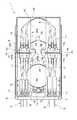
図1は、本発明に係る光ケーブル接続用クロージャの一実施形態の内部構造を示す平面図であり、図2は、その光ケーブル接続用クロージャの分解側面図である。これらの図において、本実施形態の光ケーブル接続用クロージャ(以下、単にクロージャという)1は、上部側のコネクタ付き光ケーブル2と下部側のコネクタ付き光ケーブル3と接続部分を保護するものである。また、クロージャ1は屋外設置型であり、電柱またはケーブル支持線(吊り線)に取り付けられる。
【0012】
クロージャ1は、矩形状のクロージャ本体4と、このクロージャ本体4の内部を保護するためのカバー5とを有している。カバー5は、防水性を有している。これにより、クロージャ1を屋外設置した状態においてクロージャ本体4の内部に水が入り込むことは無い。
【0013】
このクロージャ本体4の一端部の左右両側には、上部側のコネクタ付き光ケーブル2が導入されるケーブル導入部6と、下部側のコネクタ付き光ケーブル3が導入されるケーブル導入部7とがそれぞれ設けられている。
【0014】
コネクタ付き光ケーブル2,3は、図3に示すように、多心光ケーブル8と、この多心光ケーブル8を複数本の光コード9に分岐させる分岐部10と、各光コード9の先端に取り付けられたSC型の光コネクタ11とを有している。分岐部10の上面および下面には、図4に示すように分岐部10を2段に重ねた時に分岐部10の長手方向に対して位置決め拘束するための複数の突起部12が設けられている。
【0015】
このようなコネクタ付き光ケーブル2,3の分岐部10は、クロージャ本体4内におけるケーブル導入部6,7の近傍でクロージャ本体4に固定されている。図4及び図5に示すように、クロージャ本体4には受け板13が固定され、この受け板13上にコネクタ付き光ケーブル2,3の分岐部10が配置されている。受け板13には、ネジ穴(図示せず)を有する2つのケーブル固定材14が連結されており、このケーブル固定材14のネジ穴にネジ15をねじ込んで分岐部10を押し付けることで、分岐部10をクロージャ本体4に固定する。これにより、コネクタ付き光ケーブル2,3をクロージャ本体4内に安定した状態で収納することができる。
【0016】
図1及び図2に戻り、クロージャ本体4の中央部の左右両側には、コネクタ付き光ケーブル2,3の光コネクタ11が接続されるアダプタ部16が上下2段にそれぞれ配置されている。このようにアダプタ部16を2段重ねとすることにより、クロージャ本体4内の省スペース化を図ることができる。
【0017】
各アダプタ部16は、互いに対向した2対のアダプタ17a,17bを有している。そして、アダプタ部16の一側(ここでは、ケーブル導入部6,7側)の2つのアダプタ17aに、コネクタ付き光ケーブル3の光コネクタ11が並列に接続され、アダプタ部16の他側の2つのアダプタ17に、コネクタ付き光ケーブル2の光コネクタ11が並列に接続される。アダプタ部16の両側面には、アダプタ部16をクロージャ本体4に取り付けるための突起部18,19がそれぞれ設けられている。そして、突起部19の両側面には、図6に示すように、保持用凹部19aが設けられている。
【0018】
クロージャ本体4には、上下2段に配置された2つのアダプタ部16の突起部18,19をそれぞれ支持するアダプタ取付部材20,21が固定されている。アダプタ取付部材21は、図6に示すように、L字型の基部22を有し、この基部22上に下段のアダプタ部16が載置されている。これにより、コネクタ付き光ケーブル3の光コード9が通るためのスペースSをアダプタ部16の下方に確保している。
【0019】
下段のアダプタ部16の突起部18,19は、図6〜図8に示すように、ネジ23によりアダプタ取付部材20,21にそれぞれ固定されている。一方、上段のアダプタ部16の突起部18は、図6及び図7に示すように、軸部24を介してアダプタ取付部材20に回動可能に取り付けられている。また、アダプタ取付部材21には、図8に示すように、アダプタ部16の突起部19に形成された保持用凹部19aと嵌合する2つの保持用凸部21aが設けられている。
【0020】
ここで、通常は、図6の2点鎖線で示すように、上段のアダプタ部16の保持用凹部19aとアダプタ取付部材21の保持用凸部21aとを嵌合させて、上段のアダプタ部16を水平にしておく。コネクタ付き光ケーブル2,3の光コネクタ11を下段のアダプタ部16のアダプタ17a,17bに着脱するときは、図6の実線で示すように、上段のアダプタ部16を上方に回動させる。これにより、上段のアダプタ部16のアダプタ17a,17bに光コネクタ11が接続されている状態であっても、下段のアダプタ部16に対する光コネクタ11の着脱作業を妨げることはない。
【0021】
図1及び図2に戻り、クロージャ本体4における左右両側に配置されたアダプタ部16の間には、コネクタ付き光ケーブル2,3の光コード9の余長を収納する余長収納部を形成するための余長押さえ板25が配置されている。この余長押さえ板25は、クロージャ本体4の一端から他端に向けて延在していると共に、光コード9の余長をガイドするための複数のRガイド26を有している。Rガイド26は、光コード9の余長の曲げ半径を30mm以上に保つような湾曲状のガイド面26aを有している。これにより、光コード9が自重で垂れ下がったときでも、光コード9に急な曲げが加わることはなく、光コード9の損傷が防止される。
【0022】
クロージャ本体4におけるケーブル導入部6,7と反対側の端部に位置するRガイド26の上面には、図9に示すように、ヒンジ27を介してケーブル保護板28が回動自在に結合されている。このケーブル保護板28は、Rガイド26の外側のガイド面26aにガイドされた光コード9の余長を保護するためのものである。ケーブル保護板28の先端部には、2つの爪部29が設けられている。
【0023】
光コード9の余長をRガイド26の外側のガイド面26aに沿って引き回したときは、ケーブル保護板28を下方に倒す。そして、図10に示すように、ケーブル保護板28の爪部29をクロージャ本体4内に入り込むようにクロージャ本体4に引っ掛ける。これにより、光コード9の余長は、外側のガイド面26aにおいて露出したままではなく、ケーブル保護板28に保護された状態となる。従って、クロージャ本体4にカバー5を取り付ける時に、光コード9を挟み込むことが防止されるため、光コード9に損傷を与えることは無い。
【0024】
図1及び図2に戻り、以上のようなクロージャ1において、上部側のコネクタ付き光ケーブル2と下部側のコネクタ付き光ケーブル3とを接続する場合は、まずコネクタ付き光ケーブル2,3をケーブル導入部6,7よりクロージャ本体4内に導入する。そして、コネクタ付き光ケーブル2,3の分岐部10をネジ15で押し付けて固定する。次いで、コネクタ付き光ケーブル2の光コード9をアダプタ部16の下方のスペースS(図6参照)に通し、コネクタ付き光ケーブル2の光コネクタ11をアダプタ部16のアダプタ17bに接続する。このとき、光コード9の余長が長い場合は、光コード9の余長を例えば8の字に配線した状態で、コネクタ11をアダプタ17bに接続する。また、コネクタ付き光ケーブル3のコネクタ11をアダプタ部16のアダプタ17aに接続する。このときも、光コード9の余長が長い場合は、光コード9の余長を例えば8の字に配線した状態で、コネクタ11をアダプタ部17aに接続する。そして最後に、クロージャ本体4にカバー5を取り付ける。
【0025】
このようにコネクタ付き光ケーブル2,3を容易にクロージャ本体4内に導入して接続することができる。また、コネクタ付き光ケーブル2,3をクロージャ本体4内にスペース効率良く収納することができるため、クロージャ1の小型化を図ることが可能となる。
【0026】
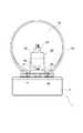
また、クロージャ本体4の裏面には、クロージャ1を電柱に取り付けるための2本の電柱取付金具30と、クロージャ1を鋼鉄製のケーブル支持線(吊り線)31に取り付けるための吊り線取付金具32とが設けられている。
【0027】
クロージャ1を電柱に取り付けるときは、図11に示すように、ステンレス等の取付バンド33を、2本の電柱取付金具30に通して電柱34に巻き付けるようにする。
【0028】
吊り線取付金具32は、クロージャ本体4の裏面に固定された取付板35を有し、この取付板35には、吊り線31を把持するための1対の把持部材36がボルト37により取り付けられている。各把持部材36の一方の側面には、例えば外径が6〜16.1mm程度の太い吊り線31と係合する把持用溝部38が設けられている。各把持部材36の他方の側面には、把持用溝部38よりも小さな寸法を有し、例えば外径が2.6〜3.2mm程度の細い吊り線31と係合する把持用溝部39が設けられている。
【0029】
このような吊り線取付金具32により、クロージャ1を太い吊り線31に取り付けるときは、図12に示すように、1対の把持部材36の各把持用溝部38を対面させて、各把持用溝部38において吊り線31を挟み、ボルト37で各把持部材36を締め付け固定する。一方、クロージャ1を細い吊り線31に取り付けるときは、図13に示すように、1対の把持部材36を図12に示す状態からひっくり返して各把持用溝部39を対面させる。そして、各把持用溝部39において吊り線31を挟み、ボルト37で各把持部材36を締め付け固定する。
【0030】
このように太い吊り線31も細い吊り線31も同一の把持部材36で把持することができるため、吊り線31の径に応じて把持部材を複数用意する必要は無い。従って、部品コストの削減を図ることができる。
【0031】
なお、本発明に係る光ケーブル接続用クロージャは、上記実施形態に限定されるものではない。
【0032】
例えば、図3に示すコネクタ付き光ケーブル2,3の代わりに、図14に示すようなコネクタ付き光ケーブル40を使用することもできる。コネクタ付き光ケーブル40は、上記の分岐部10とは構造の異なる分岐部41を有している。この分岐部41の上面には複数の位置決め用凹部42が設けられ、分岐部41の下面には複数の位置決め用凸部(図示せず)が設けられている。
【0033】
このような分岐部41をクロージャ本体4に固定する場合は、例えば、図15に示すように、上面に複数の位置決め用凹部43を有する土台44を設ける。そして、分岐部41の位置決め用凸部(図示せず)が土台44の位置決め用凹部43に嵌合するように分岐部41を土台44上に載置する。また、分岐部41を2段重ねするときは、上段の分岐部41の位置決め用凸部(図示せず)を下段の分岐部41の位置決め用凹部42に嵌合させる。その状態で、分岐部41を押さえ付ける押さえ部45aが設けられたケーブル固定材45をクロージャ本体4に取り付ける。
【0034】
また、コネクタ付き光ケーブルの光コネクタとしては、上記のSC型コネクタに限らず、FC型、LC型、MU型、MPO型のコネクタ等を使用することも可能である。
【0035】
【発明の効果】
本発明によれば、クロージャ本体内に導入された各コネクタ付き光ケーブルをクロージャ本体に固定するためのケーブル固定手段と、各コネクタ付き光ケーブルのコネクタが接続されるアダプタ部と、各コネクタ付き光ケーブルの余長が収納されるケーブル余長収納部とを設けたので、コネクタ付き光ケーブル同士を容易かつ確実に接続して保護することができる。
【図面の簡単な説明】
【図1】本発明に係る光ケーブル接続用クロージャの一実施形態の内部構造を示す平面図である。
【図2】図1に示す光ケーブル接続用クロージャの分解側面図である。
【図3】図1に示す光ケーブル接続用クロージャに適用されるコネクタ付き光ケーブルの一例を示す斜視図である。
【図4】図3に示すコネクタ付き光ケーブルの分岐部がクロージャ本体に固定された状態を示す断面図であって、クロージャ本体の側面側から見たときの図である。
【図5】図3に示すコネクタ付き光ケーブルの分岐部がクロージャ本体に固定された状態を示す断面図であって、クロージャ本体の端面側から見たときの図である。
【図6】図1に示すアダプタ部の正面図である。
【図7】図6に示す上段のアダプタ部が通常状態にあるときのVII−VII線断面図である。
【図8】図6に示す上段のアダプタ部が通常状態にあるときのVIII−VIII線断面図である。
【図9】図1に示す余長押さえ板に設けられたRガイド及びケーブル保護板を示す斜視図である。
【図10】図9に示すケーブル保護板により光コードが保護されている状態を示す斜視図である。
【図11】図1及び図2に示す光ケーブル接続用クロージャが電柱に取り付けられている状態を示す平面図である。
【図12】図1及び図2に示す光ケーブル接続用クロージャが太い吊り線に取り付けられている状態を示す側面図である。
【図13】図1及び図2に示す光ケーブル接続用クロージャが細い吊り線に取り付けられている状態を示す側面図である。
【図14】図1及び図2に示す光ケーブル接続用クロージャに適用されるコネクタ付き光ケーブルの他の例を示す斜視図である。
【図15】図14に示すコネクタ付き光ケーブルの分岐部がクロージャ本体に固定された状態を示す斜視図である
【符号の説明】
1…光ケーブル接続用クロージャ、2…コネクタ付き光ケーブル、3…コネクタ付き光ケーブル、4…クロージャ本体、5…カバー、9…光コード、10…分岐部、11…光コネクタ、14…ケーブル固定材(ケーブル固定手段)、15…ネジ(ケーブル固定手段)、16…アダプタ部、17a,17b…アダプタ、18…突起部、19…突起部、19a…保持用凹部、20…アダプタ取付部材、21…アダプタ取付部材、21a…保持用凸部、24…軸部、25…余長押さえ板(ケーブル余長収納部)、26…Rガイド(ケーブルガイド)、26a…ガイド面、27…ヒンジ、28…ケーブル保護板、31…吊り線、32…吊り線取付金具(取付手段)、36…把持部材、38…把持用溝部(第1把持用溝部)、39…把持用溝部(第2把持用溝部)、40…コネクタ付き光ケーブル、41…分岐部、45…ケーブル固定材(ケーブル固定手段)。[0001]
TECHNICAL FIELD OF THE INVENTION
The present invention relates to an optical cable connection closure used for connecting an optical communication cable or the like.
[0002]
[Prior art]
In general, as an optical cable connection closure, a closure having a connection portion such as a connector for connecting optical cords drawn out of an optical cable and an extra length storage portion for winding and storing an extra length portion of the optical cord is known. ing.
[0003]
[Problems to be solved by the invention]
Conventionally, there has been a compact optical cable connection closure for outdoor installation that can easily perform the wiring and connection work of the optical cable, but there has been almost no such closure considering the introduction of an optical cable with an optical connector.
[0004]
An object of the present invention is to provide an outdoor installation type optical cable connection closure which can easily and reliably connect and protect optical cables with connectors.
[0005]
[Means for Solving the Problems]
The closure for optical cable connection of the present invention comprises: a closure main body into which a plurality of optical cables with connectors are introduced; cable fixing means for fixing the optical cables with connectors introduced into the closure main body to the closure main body; And an adapter portion to which the connectors of the optical cables with connectors are connected, a cable extra length storage portion provided in the closure body for storing the extra length of the optical cables with connectors, and protects the inside of the closure body. And a mounting means for mounting the closure main body to the suspension line.
[0006]
In such an optical cable connection closure, an optical cable with a connector is introduced into the closure main body, and the optical cable with a connector is fixed to the closure main body by cable fixing means. Then, if necessary, the extra length of the optical cable with connector is stored in the extra cable length storage section, and the connector of the optical cable with connector is connected to the adapter section. Then, a cover is attached to the closure body. Thus, the optical cables with connectors can be easily connected to each other after the plurality of optical cables with connectors are stably housed in the closure main body. Further, by providing the cover, it is possible to prevent water from entering the closure when the optical cable connection closure is installed outdoors. Further, the attachment means enables the optical cable connection closure to be easily attached to the suspension line.
[0007]
Preferably, the adapter portions are arranged in two stages, upper and lower, and the upper adapter portion is rotatably supported by an adapter mounting member fixed to the closure body. Since the adapter section has a two-tiered structure, the space efficiency is improved, and the size of the optical cable connection closure can be reduced. In addition, when the connector of the optical cable with a connector is connected to and detached from the lower adapter section while the connector of the optical cable with the connector is connected to the upper adapter section, the work of attaching and detaching the connector is performed by rotating the upper adapter section. Can be easily performed.
[0008]
Preferably, the extra cable length storage portion is rotatably coupled to the cable guide having a curved guide surface for guiding the extra length of the optical cable with the connector, and is guided by the guide surface. A cable protection plate for protecting the extra length of the optical cable with the connector. In this case, since the extra length of the optical cable with connector is routed along the curved guide surface, it is possible to prevent the optical cable with connector from being sharply bent. Also, after the extra length of the optical cable with connector is routed along the guide surface, the cable protection plate is rotated to protect the extra length of the optical cable with connector. It is possible to prevent the extra length from being inserted.
[0009]
Furthermore, preferably, the attaching means has a pair of gripping members for gripping the hanging lines, and a first gripping groove engaging with the hanging lines is provided on one side surface of each gripping member. The other side surface of the member is provided with a second gripping groove portion that engages with the suspension wire and has a smaller size than the first gripping groove portion. In this case, when attaching the optical cable connection closure to the thick suspension line, the suspension line is gripped in each of the first holding grooves of the pair of gripping members, and when attaching the optical cable connection closure to the thin suspension line, one pair is used. The suspension line is gripped in each of the second gripping grooves of the gripping member. As described above, a plurality of suspension lines having different diameters can be dealt with by a set of gripping members, so that it is not necessary to manufacture many gripping members corresponding to the diameters of the suspension lines, which is advantageous in cost.
[0010]
BEST MODE FOR CARRYING OUT THE INVENTION
Hereinafter, a preferred embodiment of an optical cable connection closure according to the present invention will be described with reference to the drawings.
[0011]
FIG. 1 is a plan view showing the internal structure of an embodiment of the optical cable connection closure according to the present invention, and FIG. 2 is an exploded side view of the optical cable connection closure. In these figures, an optical cable connection closure (hereinafter simply referred to as a closure) 1 of the present embodiment protects a connection portion between an
[0012]
The
[0013]
On both left and right sides of one end of the
[0014]
As shown in FIG. 3, the optical cables with
[0015]
The
[0016]
Returning to FIGS. 1 and 2,
[0017]
Each
[0018]
[0019]
The protruding
[0020]
Here, usually, as shown by a two-dot chain line in FIG. 6, the holding
[0021]
Returning to FIG. 1 and FIG. 2, between the
[0022]
As shown in FIG. 9, a
[0023]
When the extra length of the
[0024]
Returning to FIGS. 1 and 2, in the above-described
[0025]
Thus, the
[0026]
Also, on the back surface of the
[0027]
When attaching the
[0028]
The hanging
[0029]
When the
[0030]
As described above, since both the
[0031]
The optical cable connection closure according to the present invention is not limited to the above embodiment.
[0032]
For example, instead of the optical cables with
[0033]
When such a
[0034]
Further, the optical connector of the optical cable with a connector is not limited to the SC type connector described above, but may be an FC type, LC type, MU type, MPO type connector, or the like.
[0035]
【The invention's effect】
According to the present invention, a cable fixing means for fixing each optical cable with a connector introduced into the closure main body to the closure main body, an adapter portion to which a connector of each optical cable with a connector is connected, and an extra portion of each optical cable with a connector. The provision of the extra cable length storage section for storing the length allows the optical cables with connectors to be easily and reliably connected and protected.
[Brief description of the drawings]
FIG. 1 is a plan view showing the internal structure of an embodiment of an optical cable connection closure according to the present invention.
FIG. 2 is an exploded side view of the optical cable connection closure shown in FIG.
FIG. 3 is a perspective view showing an example of an optical cable with a connector applied to the optical cable connection closure shown in FIG. 1;
4 is a cross-sectional view showing a state where a branch portion of the optical cable with connector shown in FIG. 3 is fixed to the closure main body, as viewed from a side of the closure main body.
5 is a cross-sectional view showing a state where a branch portion of the optical cable with connector shown in FIG. 3 is fixed to the closure main body, as viewed from an end face side of the closure main body.
FIG. 6 is a front view of the adapter section shown in FIG. 1;
FIG. 7 is a sectional view taken along line VII-VII when the upper adapter section shown in FIG. 6 is in a normal state.
8 is a sectional view taken along line VIII-VIII when the upper adapter section shown in FIG. 6 is in a normal state.
FIG. 9 is a perspective view showing an R guide and a cable protection plate provided on the extra length holding plate shown in FIG. 1;
FIG. 10 is a perspective view showing a state in which the optical cord is protected by the cable protection plate shown in FIG.
FIG. 11 is a plan view showing a state in which the optical cable connection closure shown in FIGS. 1 and 2 is attached to a telephone pole.
FIG. 12 is a side view showing a state where the optical cable connection closure shown in FIGS. 1 and 2 is attached to a thick suspension line.
FIG. 13 is a side view showing a state where the optical cable connection closure shown in FIGS. 1 and 2 is attached to a thin suspension line.
FIG. 14 is a perspective view showing another example of an optical cable with a connector applied to the optical cable connection closure shown in FIGS. 1 and 2;
15 is a perspective view showing a state where a branch portion of the optical cable with a connector shown in FIG. 14 is fixed to a closure main body.
DESCRIPTION OF
Claims (4)
Translated fromJapanese前記クロージャ本体内に導入された前記各コネクタ付き光ケーブルを前記クロージャ本体に固定するためのケーブル固定手段と、
前記クロージャ本体内に設けられ、前記各コネクタ付き光ケーブルのコネクタが接続されるアダプタ部と、
前記クロージャ本体内に設けられ、前記各コネクタ付き光ケーブルの余長が収納されるケーブル余長収納部と、
前記クロージャ本体の内部を保護するためのカバーと、
前記クロージャ本体を吊り線に取り付けるための取付手段とを備えることを特徴とする光ケーブル接続用クロージャ。A closure body into which a plurality of optical cables with connectors are introduced;
Cable fixing means for fixing the optical cable with each connector introduced into the closure main body to the closure main body,
An adapter unit provided in the closure main body, to which a connector of the optical cable with each connector is connected;
A cable extra length storage portion that is provided in the closure main body and stores an extra length of the optical cable with each connector;
A cover for protecting the inside of the closure body,
An attachment means for attaching the closure main body to a suspension line.
上段の前記アダプタ部は、前記クロージャ本体に固定された前記アダプタ取付部材に回動可能に支持されていることを特徴とする請求項1記載の光ケーブル接続用クロージャ。The adapter unit is disposed in two stages, upper and lower,
2. The optical cable connection closure according to claim 1, wherein the upper adapter portion is rotatably supported by the adapter mounting member fixed to the closure main body.
前記各把持部材の一方の側面には、前記吊り線と係合する第1把持用溝部が設けられ、前記各把持部材の他方の側面には、前記吊り線と係合し前記第1把持用溝部よりも小さい寸法を有する第2把持用溝部が設けられていることを特徴とする請求項1〜3のいずれか一項記載の光ケーブル接続用クロージャ。The mounting means has a pair of gripping members for gripping the hanging line,
On one side of each of the gripping members, a first gripping groove is provided for engaging with the hanging line, and on the other side of each of the gripping members, the first gripping groove is engaged with the hanging line. The optical cable connection closure according to any one of claims 1 to 3, wherein a second gripping groove having a smaller size than the groove is provided.
Priority Applications (1)
| Application Number | Priority Date | Filing Date | Title |
|---|---|---|---|
| JP2002217997AJP3814234B2 (en) | 2002-07-26 | 2002-07-26 | Optical cable connection closure |
Applications Claiming Priority (1)
| Application Number | Priority Date | Filing Date | Title |
|---|---|---|---|
| JP2002217997AJP3814234B2 (en) | 2002-07-26 | 2002-07-26 | Optical cable connection closure |
Publications (2)
| Publication Number | Publication Date |
|---|---|
| JP2004061713Atrue JP2004061713A (en) | 2004-02-26 |
| JP3814234B2 JP3814234B2 (en) | 2006-08-23 |
Family
ID=31939308
Family Applications (1)
| Application Number | Title | Priority Date | Filing Date |
|---|---|---|---|
| JP2002217997AExpired - LifetimeJP3814234B2 (en) | 2002-07-26 | 2002-07-26 | Optical cable connection closure |
Country Status (1)
| Country | Link |
|---|---|
| JP (1) | JP3814234B2 (en) |
Cited By (14)
| Publication number | Priority date | Publication date | Assignee | Title |
|---|---|---|---|---|
| WO2009032086A3 (en)* | 2007-09-05 | 2009-06-04 | Corning Cable Sys Llc | Fiber optic terminal assembly |
| US8467651B2 (en) | 2009-09-30 | 2013-06-18 | Ccs Technology Inc. | Fiber optic terminals configured to dispose a fiber optic connection panel(s) within an optical fiber perimeter and related methods |
| US8520996B2 (en) | 2009-03-31 | 2013-08-27 | Corning Cable Systems Llc | Removably mountable fiber optic terminal |
| KR101413748B1 (en)* | 2012-06-11 | 2014-07-01 | 주식회사 로제 | Optical cable connection divergence box and optical cable monitoring system |
| US8792767B2 (en) | 2010-04-16 | 2014-07-29 | Ccs Technology, Inc. | Distribution device |
| US8879882B2 (en) | 2008-10-27 | 2014-11-04 | Corning Cable Systems Llc | Variably configurable and modular local convergence point |
| US8909019B2 (en) | 2012-10-11 | 2014-12-09 | Ccs Technology, Inc. | System comprising a plurality of distribution devices and distribution device |
| US9004778B2 (en) | 2012-06-29 | 2015-04-14 | Corning Cable Systems Llc | Indexable optical fiber connectors and optical fiber connector arrays |
| US9049500B2 (en) | 2012-08-31 | 2015-06-02 | Corning Cable Systems Llc | Fiber optic terminals, systems, and methods for network service management |
| US9219546B2 (en) | 2011-12-12 | 2015-12-22 | Corning Optical Communications LLC | Extremely high frequency (EHF) distributed antenna systems, and related components and methods |
| US9323020B2 (en) | 2008-10-09 | 2016-04-26 | Corning Cable Systems (Shanghai) Co. Ltd | Fiber optic terminal having adapter panel supporting both input and output fibers from an optical splitter |
| US9547144B2 (en) | 2010-03-16 | 2017-01-17 | Corning Optical Communications LLC | Fiber optic distribution network for multiple dwelling units |
| US9547145B2 (en) | 2010-10-19 | 2017-01-17 | Corning Optical Communications LLC | Local convergence point for multiple dwelling unit fiber optic distribution network |
| US10110307B2 (en) | 2012-03-02 | 2018-10-23 | Corning Optical Communications LLC | Optical network units (ONUs) for high bandwidth connectivity, and related components and methods |
Citations (14)
| Publication number | Priority date | Publication date | Assignee | Title |
|---|---|---|---|---|
| JPS60184006U (en)* | 1984-05-17 | 1985-12-06 | 株式会社フジクラ | Fiber optic cable connection |
| JPS61155805U (en)* | 1985-03-19 | 1986-09-27 | ||
| JPH03245109A (en)* | 1990-02-23 | 1991-10-31 | Sumitomo Electric Ind Ltd | optical fiber junction box |
| JPH0411501U (en)* | 1990-05-21 | 1992-01-30 | ||
| JPH0624342U (en)* | 1992-07-27 | 1994-03-29 | ホーチキ株式会社 | Messenger wire mounting device for co-listening equipment |
| JPH07199015A (en)* | 1993-12-28 | 1995-08-04 | Sumitomo Electric Ind Ltd | Connector extra length handling method and connection box for optical cable with connector |
| JPH08201634A (en)* | 1995-01-25 | 1996-08-09 | Sumitomo Electric Ind Ltd | Method and structure for processing excess length of connection part of optical cable with connector |
| JPH08227018A (en)* | 1995-02-22 | 1996-09-03 | Fujikura Ltd | Optical cable closure |
| JPH08248238A (en)* | 1995-03-07 | 1996-09-27 | Shiyoudenshiya:Kk | Stacked optical fiber core storage case |
| JPH0923533A (en)* | 1995-07-03 | 1997-01-21 | Sankooshiya:Kk | Closure for communication cable |
| JPH09504380A (en)* | 1993-09-08 | 1997-04-28 | エヌ・ヴェ・レイケム・ソシエテ・アノニム | Optical fiber organizer |
| JPH10197727A (en)* | 1997-01-09 | 1998-07-31 | Fujitsu Denso Ltd | Optical cable excessive length processor |
| JPH10311931A (en)* | 1997-05-12 | 1998-11-24 | Fujikura Ltd | Optical branch module, optical wiring method, and work jig |
| JPH11185866A (en)* | 1997-12-19 | 1999-07-09 | Seiwa Electric Mfg Co Ltd | Cable connection box |
- 2002
- 2002-07-26JPJP2002217997Apatent/JP3814234B2/ennot_activeExpired - Lifetime
Patent Citations (14)
| Publication number | Priority date | Publication date | Assignee | Title |
|---|---|---|---|---|
| JPS60184006U (en)* | 1984-05-17 | 1985-12-06 | 株式会社フジクラ | Fiber optic cable connection |
| JPS61155805U (en)* | 1985-03-19 | 1986-09-27 | ||
| JPH03245109A (en)* | 1990-02-23 | 1991-10-31 | Sumitomo Electric Ind Ltd | optical fiber junction box |
| JPH0411501U (en)* | 1990-05-21 | 1992-01-30 | ||
| JPH0624342U (en)* | 1992-07-27 | 1994-03-29 | ホーチキ株式会社 | Messenger wire mounting device for co-listening equipment |
| JPH09504380A (en)* | 1993-09-08 | 1997-04-28 | エヌ・ヴェ・レイケム・ソシエテ・アノニム | Optical fiber organizer |
| JPH07199015A (en)* | 1993-12-28 | 1995-08-04 | Sumitomo Electric Ind Ltd | Connector extra length handling method and connection box for optical cable with connector |
| JPH08201634A (en)* | 1995-01-25 | 1996-08-09 | Sumitomo Electric Ind Ltd | Method and structure for processing excess length of connection part of optical cable with connector |
| JPH08227018A (en)* | 1995-02-22 | 1996-09-03 | Fujikura Ltd | Optical cable closure |
| JPH08248238A (en)* | 1995-03-07 | 1996-09-27 | Shiyoudenshiya:Kk | Stacked optical fiber core storage case |
| JPH0923533A (en)* | 1995-07-03 | 1997-01-21 | Sankooshiya:Kk | Closure for communication cable |
| JPH10197727A (en)* | 1997-01-09 | 1998-07-31 | Fujitsu Denso Ltd | Optical cable excessive length processor |
| JPH10311931A (en)* | 1997-05-12 | 1998-11-24 | Fujikura Ltd | Optical branch module, optical wiring method, and work jig |
| JPH11185866A (en)* | 1997-12-19 | 1999-07-09 | Seiwa Electric Mfg Co Ltd | Cable connection box |
Cited By (19)
| Publication number | Priority date | Publication date | Assignee | Title |
|---|---|---|---|---|
| WO2009032086A3 (en)* | 2007-09-05 | 2009-06-04 | Corning Cable Sys Llc | Fiber optic terminal assembly |
| US8798427B2 (en) | 2007-09-05 | 2014-08-05 | Corning Cable Systems Llc | Fiber optic terminal assembly |
| US9323020B2 (en) | 2008-10-09 | 2016-04-26 | Corning Cable Systems (Shanghai) Co. Ltd | Fiber optic terminal having adapter panel supporting both input and output fibers from an optical splitter |
| US8879882B2 (en) | 2008-10-27 | 2014-11-04 | Corning Cable Systems Llc | Variably configurable and modular local convergence point |
| US8520996B2 (en) | 2009-03-31 | 2013-08-27 | Corning Cable Systems Llc | Removably mountable fiber optic terminal |
| US8467651B2 (en) | 2009-09-30 | 2013-06-18 | Ccs Technology Inc. | Fiber optic terminals configured to dispose a fiber optic connection panel(s) within an optical fiber perimeter and related methods |
| US9547144B2 (en) | 2010-03-16 | 2017-01-17 | Corning Optical Communications LLC | Fiber optic distribution network for multiple dwelling units |
| US8792767B2 (en) | 2010-04-16 | 2014-07-29 | Ccs Technology, Inc. | Distribution device |
| US9547145B2 (en) | 2010-10-19 | 2017-01-17 | Corning Optical Communications LLC | Local convergence point for multiple dwelling unit fiber optic distribution network |
| US9720197B2 (en) | 2010-10-19 | 2017-08-01 | Corning Optical Communications LLC | Transition box for multiple dwelling unit fiber optic distribution network |
| US9219546B2 (en) | 2011-12-12 | 2015-12-22 | Corning Optical Communications LLC | Extremely high frequency (EHF) distributed antenna systems, and related components and methods |
| US9602209B2 (en) | 2011-12-12 | 2017-03-21 | Corning Optical Communications LLC | Extremely high frequency (EHF) distributed antenna systems, and related components and methods |
| US9800339B2 (en) | 2011-12-12 | 2017-10-24 | Corning Optical Communications LLC | Extremely high frequency (EHF) distributed antenna systems, and related components and methods |
| US10110305B2 (en) | 2011-12-12 | 2018-10-23 | Corning Optical Communications LLC | Extremely high frequency (EHF) distributed antenna systems, and related components and methods |
| US10110307B2 (en) | 2012-03-02 | 2018-10-23 | Corning Optical Communications LLC | Optical network units (ONUs) for high bandwidth connectivity, and related components and methods |
| KR101413748B1 (en)* | 2012-06-11 | 2014-07-01 | 주식회사 로제 | Optical cable connection divergence box and optical cable monitoring system |
| US9004778B2 (en) | 2012-06-29 | 2015-04-14 | Corning Cable Systems Llc | Indexable optical fiber connectors and optical fiber connector arrays |
| US9049500B2 (en) | 2012-08-31 | 2015-06-02 | Corning Cable Systems Llc | Fiber optic terminals, systems, and methods for network service management |
| US8909019B2 (en) | 2012-10-11 | 2014-12-09 | Ccs Technology, Inc. | System comprising a plurality of distribution devices and distribution device |
Also Published As
| Publication number | Publication date |
|---|---|
| JP3814234B2 (en) | 2006-08-23 |
Similar Documents
| Publication | Publication Date | Title |
|---|---|---|
| JP2004061713A (en) | Closure for optical cable connection | |
| US5553186A (en) | Fiber optic dome closure | |
| JP5138947B2 (en) | Optical cable closure | |
| US7340144B2 (en) | Optical fiber splice enclosure | |
| JPH11502946A (en) | Closed container with cable strain relief | |
| US20010036351A1 (en) | Fiber optic wall mount cabinet | |
| KR19980703324A (en) | Fiber optic splice structure | |
| WO1996030794A1 (en) | Optical fibre cable connector with shielding and strain relief for optical fibre cable closure | |
| RU2005116979A (en) | TELECOMMUNICATION TERMINAL | |
| JP4751212B2 (en) | Optical fiber branch cable, wiring method thereof, and providing method thereof | |
| US5892177A (en) | Hinged cable routing apparatus | |
| JP3963776B2 (en) | Optical cable connector | |
| JP2001194536A (en) | Optical connection box and optical connection method | |
| JPH10133030A (en) | Storage case for optical cable connection | |
| US11009672B2 (en) | Device and method for aerially suspending an optical cable termination box | |
| JP3062426U (en) | Storage structure for optical cable connection | |
| CN222461745U (en) | Terminal Box | |
| JP4745162B2 (en) | Optical termination box for branching | |
| JPH08248236A (en) | Storage and workbench for connecting aerial optical fiber cables | |
| JP2903021B1 (en) | Extra storage case and optical distribution board | |
| JPS61223809A (en) | Terminal board of optical connector | |
| CN114868058B (en) | Terminal system components with branch/adapter modules | |
| JP4458539B2 (en) | Optical cable connector | |
| JPH0350242B2 (en) | ||
| JPH10300946A (en) | Adapter device in cabinet for storing optical cable connection |
Legal Events
| Date | Code | Title | Description |
|---|---|---|---|
| A977 | Report on retrieval | Free format text:JAPANESE INTERMEDIATE CODE: A971007 Effective date:20050314 | |
| A131 | Notification of reasons for refusal | Free format text:JAPANESE INTERMEDIATE CODE: A131 Effective date:20050322 | |
| A521 | Request for written amendment filed | Free format text:JAPANESE INTERMEDIATE CODE: A523 Effective date:20050518 | |
| TRDD | Decision of grant or rejection written | ||
| A01 | Written decision to grant a patent or to grant a registration (utility model) | Free format text:JAPANESE INTERMEDIATE CODE: A01 Effective date:20060523 | |
| A61 | First payment of annual fees (during grant procedure) | Free format text:JAPANESE INTERMEDIATE CODE: A61 Effective date:20060602 | |
| R150 | Certificate of patent or registration of utility model | Free format text:JAPANESE INTERMEDIATE CODE: R150 Ref document number:3814234 Country of ref document:JP Free format text:JAPANESE INTERMEDIATE CODE: R150 | |
| FPAY | Renewal fee payment (event date is renewal date of database) | Free format text:PAYMENT UNTIL: 20090609 Year of fee payment:3 | |
| FPAY | Renewal fee payment (event date is renewal date of database) | Free format text:PAYMENT UNTIL: 20100609 Year of fee payment:4 | |
| R250 | Receipt of annual fees | Free format text:JAPANESE INTERMEDIATE CODE: R250 | |
| FPAY | Renewal fee payment (event date is renewal date of database) | Free format text:PAYMENT UNTIL: 20110609 Year of fee payment:5 | |
| R250 | Receipt of annual fees | Free format text:JAPANESE INTERMEDIATE CODE: R250 | |
| FPAY | Renewal fee payment (event date is renewal date of database) | Free format text:PAYMENT UNTIL: 20110609 Year of fee payment:5 | |
| FPAY | Renewal fee payment (event date is renewal date of database) | Free format text:PAYMENT UNTIL: 20120609 Year of fee payment:6 | |
| R250 | Receipt of annual fees | Free format text:JAPANESE INTERMEDIATE CODE: R250 | |
| FPAY | Renewal fee payment (event date is renewal date of database) | Free format text:PAYMENT UNTIL: 20120609 Year of fee payment:6 | |
| FPAY | Renewal fee payment (event date is renewal date of database) | Free format text:PAYMENT UNTIL: 20130609 Year of fee payment:7 | |
| R250 | Receipt of annual fees | Free format text:JAPANESE INTERMEDIATE CODE: R250 | |
| FPAY | Renewal fee payment (event date is renewal date of database) | Free format text:PAYMENT UNTIL: 20140609 Year of fee payment:8 | |
| R250 | Receipt of annual fees | Free format text:JAPANESE INTERMEDIATE CODE: R250 | |
| S531 | Written request for registration of change of domicile | Free format text:JAPANESE INTERMEDIATE CODE: R313531 | |
| R350 | Written notification of registration of transfer | Free format text:JAPANESE INTERMEDIATE CODE: R350 | |
| R250 | Receipt of annual fees | Free format text:JAPANESE INTERMEDIATE CODE: R250 | |
| R250 | Receipt of annual fees | Free format text:JAPANESE INTERMEDIATE CODE: R250 | |
| R250 | Receipt of annual fees | Free format text:JAPANESE INTERMEDIATE CODE: R250 | |
| R250 | Receipt of annual fees | Free format text:JAPANESE INTERMEDIATE CODE: R250 | |
| R250 | Receipt of annual fees | Free format text:JAPANESE INTERMEDIATE CODE: R250 | |
| R250 | Receipt of annual fees | Free format text:JAPANESE INTERMEDIATE CODE: R250 | |
| R250 | Receipt of annual fees | Free format text:JAPANESE INTERMEDIATE CODE: R250 | |
| R250 | Receipt of annual fees | Free format text:JAPANESE INTERMEDIATE CODE: R250 | |
| R250 | Receipt of annual fees | Free format text:JAPANESE INTERMEDIATE CODE: R250 | |
| EXPY | Cancellation because of completion of term |