JP2004045266A - Method and apparatus for detecting three-dimensional information - Google Patents
Method and apparatus for detecting three-dimensional informationDownload PDFInfo
- Publication number
- JP2004045266A JP2004045266AJP2002204189AJP2002204189AJP2004045266AJP 2004045266 AJP2004045266 AJP 2004045266AJP 2002204189 AJP2002204189 AJP 2002204189AJP 2002204189 AJP2002204189 AJP 2002204189AJP 2004045266 AJP2004045266 AJP 2004045266A
- Authority
- JP
- Japan
- Prior art keywords
- light
- visible region
- distance
- imaging
- intensity
- Prior art date
- Legal status (The legal status is an assumption and is not a legal conclusion. Google has not performed a legal analysis and makes no representation as to the accuracy of the status listed.)
- Granted
Links
Images


Landscapes
- Studio Devices (AREA)
- Length Measuring Devices By Optical Means (AREA)
- Transforming Light Signals Into Electric Signals (AREA)
Abstract
Translated fromJapaneseDescription
Translated fromJapanese【0001】
【発明の属する技術分野】
本発明は3次元情報検出方法及び装置に関し、特に、被写体の奥行き形状を検出し3次元情報を取得する3次元情報検出方法及び装置に関する。
【0002】
【従来の技術】
物体の3次元位置もしくは奥行き距離の検出方法として、複数台のカメラを使用して得られた多視点画像より3次元情報を取得するステレオ法がある。また、光を照射し距離を検出する方法として、照射光を正弦波駆動し反射側で位相を検出して距離を算出する方法がある。
【0003】
また、特願平10−293817号公報には、照射光の時間変化と撮像側のゲイン変調の組合せを2種類選ぶことで撮影された2枚の画像より高速に距離を算出することが記載されている。
【0004】
【発明が解決しようとする課題】
ステレオ法による3次元情報の取得方法では、光を照射する必要がないため、外光の影響を受けないというメリットがある反面、複数台のカメラの配置やカメラレンズのキャリブレーションが煩雑であり、また、装置が大型であり汎用性に欠ける。更にカメラレンズのズーム操作により自由な撮影画角変更ができない。更に、標準テレビジョン画像程度以上の高精細な画像において、画素ごとに距離を算出するには、複数画像間で対応点を検索する画像マッチング処理に時間を要するため、ビデオレート(フレームレート60Hz)程度の高速で、かつ、40万画素以上の多画素検出は困難であるという問題があった。
【0005】
また、正弦波状の光を被写体に照射し反射側でその位相を検出する方式では、撮影画素ごとに光の位相を算出していく必要があり、一般的に実用化レベルにあるレンジファインダで被写体全体の距離を検出する場合は、光ビームの2次元走査機構が必要であるため、高速性が損なわれてしまうとともに構成も複雑となってしまうという問題があった。
【0006】
また、特願平10−293817号公報では、高速に距離画像(距離の情報を画像信号の輝度で表した画像)を取得する方法を示しているが、カラー映像と同じ画角の距離映像を同時に撮影し、しかも距離検出のオクルージョンがなく、ハイビジョン映像クラスの高品質な映像の撮影を可能とし、カメラレンズのズーム機能に対応してカラー画像と距離映像を連動する具体的な方法については考慮されていないという問題があった。
【0007】
本発明は、上記の点に鑑みなされたもので、高精細な画像の距離映像をビデオレートで取得でき、カメラレンズのズーム機能に対応したカラー映像と距離映像を取得することができる3次元情報検出方法及び装置を提供することを目的とする。
【0008】
【課題を解決するための手段】
請求項1,2に記載の発明は、可視領域外の光を強度変調して被写体に照射すると共に可視領域の光を前記被写体に照射し、
カメラレンズで集光された前記被写体からの反射光を可視領域外の光と可視領域の光とに波長分離し、
撮像ゲインを変調して前記波長分離された可視領域外の光学像を撮像し、
前記波長分離された可視領域の光学像を撮影し映像信号を出力し、
前記可視領域外の光の強度変調と前記撮像ゲインの変調との時間変化パターンが異なる組合せであるときに前記可視領域外の光学像を撮像した複数の画像間の強度比から距離を算出し、距離を明暗で表す距離映像信号を出力することにより、
高精細な画像の距離映像をビデオレートで取得でき、カメラレンズのズーム機能に対応したカラー映像と距離映像を取得することができる。
【0009】
請求項3に記載の発明は、請求項2記載の3次元情報検出装置において、
前記カメラレンズは、ズーム機能を有することにより、
カメラレンズでズーミングを行った後に可視領域外の光と可視領域の光とに波長分離されるので、カメラレンズのズーム機能に対応したカラー映像と距離映像を取得することができる。
【0010】
請求項4に記載の発明は、請求項2または3記載の3次元情報検出装置において、
前記第1光照射手段は、照射する可視領域外の光の光軸がカメラレンズの光軸に近接するよう、カメラレンズの周囲に配置したことにより、
可視領域外の光照射で発生する影を小さくして、被写体において距離検出ができない部分を縮小できる。
【0011】
請求項5に記載の発明は、請求項2または3記載の3次元情報検出装置において、
前記第1光照射手段が照射する可視領域外の光の光軸を前記カメラレンズの光軸に一致させる光軸一致手段を有することにより、
可視領域外の光照射で発生する影をなくし、被写体において距離検出ができない部分をなくすことができる。
【0012】
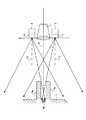
【発明の実施の形態】
図1は、本発明の3次元情報検出装置の第1実施例の構成図を示す。同図中、第1光源2の出力光を光照射光学系3を通して、撮影対象の被写体1を含む撮影範囲の全体に照射する。このとき、照射光は光強度が時間軸方向に変化する強度変調光4である。第1光源2としては1個もしくは複数個のレーザダイオードや発光ダイオードが使用できる。
【0013】
また、第1光源2の出力光の波長はカラー画像撮影に必要な可視領域の波長以外の波長が使用でき、例えば紫外領域や赤外領域の波長が使用できる。特に、750nm〜900nmの近赤外光は、可視領域に波長が近く光学特性が可視領域と大きく異ならないため、通常のカラー画像撮影用のカメラレンズを使用でき、また、後述の色分離結像光学系8においても、可視領域との波長分離を高い効率で行える。
光学的に高い色分離結像光学系率を確保する光学系を作製することが容易である。
【0014】
強度変調光4の生成手段としては、半導体レーザや発光ダイオードの駆動電流を直接変調しても良く、また、光源出力光を音響光学素子などの外部変調器を通して変調してもよい。光照射光学系3としては、例えば出力端面に微小レンズを使用し、照射する被写体の範囲に応じたレンズ形状を採用する。照明の照射強度の均一性を確保するためには、光ファイバ束を用い、各光ファイバに微小レンズを配置し照射面で個々の照射パターンを重畳することで、照射光強度の均一性を高めることができる。
【0015】
更に、光照射光学系3としては、拡散板を使用することもできる。拡散板としては、すりガラス状の散乱効果を示すもの、または表面に細かい回折格子上の凹凸を形成し、回折効果により光の配光制御を行う素子が使用できる。特に、表面回折を使用した拡散板に関しては、表面の凹凸の形成パターンにより、光の配光形状や強度分布が制御できるため、撮影アスペクト比に応じ効率よく均一な照明が実現できる。また、拡散板を用いることで面光源と同様の条件となり、点光源に比較し人物撮影時の目への負担が少なくなり、安全性が確保できる。
【0016】
被写体1は、可視光5を照射する第2光源6で照明されている。この第2光源6は、カメラレンズ7の近傍にある必要はない。第1光源2に近赤外光を使用した場合、第2光源6としては近赤外成分がほとんど含まれていない蛍光灯照明が使用できる。
【0017】
上記第1光源2及び第2光源6で照明された被写体1からの反射光は、カメラレンズ7により集光される。カメラレンズの特性としては、通常のカラー画像撮影用のズーム機能付カメラレンズを使用することができる。また、第1光源の波長に応じた表面コーティングを施すことにより、第1光源2の光を効率よく取り込めるとともに、レンズ内でのゴーストの発生を抑えることができ、距離検出性能と高画質映像の取得に有利である。
【0018】
カメラレンズ7の後段に、第1光源2からの光波長成分と第2光源からの光波長成分とを色分離し、それぞれ結像する色分離結像光学系8が配置されている。第1光源2からの光成分の結像画像は高速に撮像ゲインを可変できる高速撮像素子9に入射される。
【0019】
高速撮像素子9は第1光源2の強度変調光の時間変化が異なる条件下で、撮像ゲインを変調して複数の画像を撮影する。信号処理部10は、得られた複数の画像の信号をもとにカメラから被写体1までの距離を算出する信号処理を行い、被写体1の奥行き距離を画像の濃淡で表す距離映像信号11を出力する。
【0020】
一方、色分離結像光学系8で分離された第2光源6からの光成分の結像画像はカラーカメラ12に入射され、カラーカメラ12はカラー映像信号13を出力する。
【0021】
図2に、第1光源2及び光照射光学系3の配置の一実施例を示す。第1光源2はカメラレンズ7の近傍に設置し、カメラレンズ7の撮影光軸14と光源2の光照射光軸15を近づけて配置することで、照明光の影を低減する。図2に示すようにカメラレンズ7より距離dで、カメラレンズ7の光軸上に位置する被写体1が、奥行きΔdの段差を持っている場合、カメラレンズ7の撮影光軸14から距離lだけ離れた位置にある光照射光学系3からの光は、被写体の一部に影16を生じ、その幅Δlは、(1)式で表される。
【0022】
Δl=l・Δd/d …(1)
(1)式から明らかなように、カメラレンズ7の撮影光軸14と光源2の光照射光軸15間の距離lを小さくするほど影の領域を小さくすることができる。
【0023】
図3に、カメラレンズ7の両脇に光源を配置した実施例を示す。カメラレンズ7の両脇に、第1光源2,2’及び光照射光学系3,3’を配置することで、片側の第1光源2による照明の影16部分を、もう一方の光源2’からの光を照射することができる。このように、カメラレンズ7の光軸14と照射光軸15,15’を近づけると共に、カメラレンズ7をその左右や上下から挟むように配置することで、距離検出のオクルージョンとなる照明の影16を低減することができる。
【0024】
また、図3では一方の光源2で照明の影16となる部分は、他方の光源2’で照明され、両方の光源で照らされている部分に比して約半分の光量となり、光の強度ムラが生じる。
【0025】
また、図4に示すように、被写体1のカメラレンズ7の光軸14を挟む位置に突起1a,1bがあり、突起1a,1bが光源2,2’による照明を阻んでいる特殊な場合は照明の影16’が生じる。これらの場合はカメラレンズ7の光軸14と照明光の照射光軸15,15’を一致させることで、これらの強度ムラや距離検出のオクルージョンとなる影の発生をなくすことができる。
【0026】
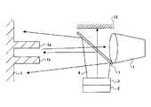
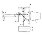
図5に、撮影光軸と照射光軸を一致させる方法を示す。同図中、カメラレンズ7の前面にハーフミラー17をカメラレンズ7の撮影光軸14に対し45度傾けて配置し、撮影光軸14に直交する方向から第1光源2及び光照射光学系3でハーフミラー17を介して照明を行う。光照射光学系3の出力する強度変調光4は、ハーフミラー17で90度反射され、カメラレンズ7の撮影光軸14と一致する光軸15にて被写体1を照明する。
【0027】
これにより、照明の影16,16’や、光の強度ムラをなくすことができる。なお、強度変調光4のうち、ハーフミラー17で反射せずに透過した光は、この波長の光を吸収する特性を持つ遮光体18により吸収される。
【0028】
また、ハーフミラー17の代わりに、図6に示すように、偏光ビームスプリッタ19を用いることもできる。この場合、強度変調光4の偏光方向を偏光ビームスプリッタ19により反射する方向にそろえる。無偏光の場合は、偏光方向をそろえるための偏光変換素子を光照射光学系3の直後に配置して、偏光方向をそろえてもよい。強度変調光4の大部分は、偏光ビームスプリッタ19で90度反射される。
【0029】
出力光はλ/4板20を透過して円偏光となり、被写体1に照射される。反射光成分の円偏光に近い反射成分は、再びλ/4板20に入射して直線偏光となり、偏光ビームスプリッタ19を透過しカメラレンズ7へ入射される。
【0030】
一方、第1光源2からの出力光の一部は偏光ビームスプリッタ19を透過するため、この波長成分の光に対し吸収が大きい遮光板18を設置し、カメラレンズ方向への反射を抑える。また、遮光板18の代わりに、偏光保存するミラーを配置し、再度光照射光学系3側へ反射させることもできる。このように、偏光ビームスプリッタ19を使うことで光源出力光の光利用効率を高くすることができる。
【0031】
ところで、照射光の照射角は、第1光源2の前に取り付けた光照射光学系3により制御する。図7に、光照射光学系3の一実施例を示す。同図中、第1光源2は複数の光源から構成され、個々の光源の出力端に1個もしくは複数個のレンズ21を取り付け、使用するカメラレンズ7で撮影される最大の画角に広げ光を照射する。
【0032】
このとき、レンズの縦方向と横方向で広がり角が異なるレンズ、例えば2焦点レンズや焦点距離が異なるシリンドリカルレンズをそれぞれ縦置きと横置きとして光照射光学系3を構成し、カメラ映像の画角に応じた形状の光照射をすることで、光の利用効率を高めることができる。
【0033】
例えば標準テレビジョンカメラを使用する場合は、横縦比率を4:3、ハイビジョン撮影の場合は16:9とする。また、光照射光学系3に、拡散板22を使用することもできる。拡散板としては、すりガラス状の散乱効果を示すもの、または表面に細かい回折格子上の凹凸を形成し、回折効果により光の配光制御を行う素子が使用できる。
【0034】
特に、表面回折を使用した拡散板に関しては、表面の凹凸の形成パターンにより、光の配光形状や強度分布が制御できるため、撮影画角に応じ効率よく均一性のよい照明が実現できる。
【0035】
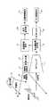
ここで、強度変調光として時間と共に光強度が増加および減少する光と、短時間シャッタ機能を持つ撮像装置による距離検出方法について説明する。距離dに置かれた被写体に、図8(A)に示すように、時間と共に係数sで光強度が増加する強度変調光23を照射し、被写体からの反射光24を時刻tsにパルス状撮像ゲイン25で短時間撮像した場合、高速撮像素子9で検出される信号量E+(d,ts)は、(2)式で表される。
【0036】
【数1】
【0037】
次に、図8(B)に示すように、時間と共に係数sで光強度が減少する強度変調光26を照射し、被写体1からの反射光27を時刻tsにパルス状撮像ゲイン25で短時間撮像した場合、高速撮像素子9で検出される信号量E−(d,ts)は、(3)式で表される。
【0038】
【数2】
【0039】
(2)式と(3)式より、光強度の異なる2枚の画像間での強度比R=E+/E−をとり、距離dを求めると、(4)式となる。
【0040】
【数3】
【0041】
このように、時間と共に強度変化する光源は、数十MHzの低い周波数でも実現できるため、レーザ光源以外に、LED(発光ダイオード)などインコヒーレントな照明も使用でき、高輝度で広い範囲を照明でき、人物の距離検出なども可能となる。なお、この方法による距離の検出範囲は、撮像時刻tsと変調周波数fで決まり、(5)式で表される。
【0042】
【数4】
【0043】
dr=c/4f …(6)
測定レンジdrが7.5mのとき変調周波数fは10MHzとなり、測定レンジdrが1.5mのとき変調周波数fは50MHzとなる。一方、撮像時の撮像時間幅Δtは光源2の変調周期1/fより短く、数nsecのシャッタ機能が必要である。
【0044】
次に、強度変調光として短時間のパルス光を使用し、高速撮像素子9の撮像ゲインを時間と共に高速に増加させながら撮像した画像と、撮像ゲインを時間と共に高速に減少させながら撮像した画像間で演算を行い、距離を検出する方法を説明する。
【0045】
距離dの位置にある被写体1に、図9(A)に示すように、光強度F0のパルス光28を時刻tpに照射し、被写体1からの反射光29を時間と共に係数gで増加する撮像ゲイン30を持つ高速撮像素子9で撮像した場合のカメラで検出される信号量E+(d,tp)は、(7)式で表される。
【0046】
【数5】
【0047】
次に、図9(B)に示すように、時間と共に係数gで減少する撮像ゲイン31を持つ高速撮像素子9で撮像した場合のカメラで検出される信号量E−(d,tp)は、(8)式で表される。
【0048】
【数6】
【0049】
(7)式と(8)式より、撮像ゲインの異なる2枚の画像間での強度比R=E+/E−をとり、距離dを求めると、(9)式となる。
【0050】
【数7】
【0051】
このように、パルス状の光と、時間と共に変化する撮像ゲインの組合せでは、パルスレーザが使用でき、Qスイッチパルスレーザ光、モード同期パルス光など、パルス幅がピコ秒からフェムト秒のパルスレーザ光が使用できるため、分解能が高い距離検出が可能となる。
【0052】
この場合、測定できる範囲(測定レンジ)Dは、(10)式で表される。
【0053】
【数8】
【0054】
【数9】
【0055】
次に、図10(B)に示すように、周期Tだけシフトした強度変調光32と逆位相の矩形状の撮像ゲイン35(ゲインg、周期T)で撮像する場合、カメラで検出される信号量E−(d,tp)は、(12)式で表される。
【0056】
【数10】
【0057】
(11)式と(12)式より、2つの画像間の強度比R=E+/E−をとり、距離dを求めると、(13)式となる。
【0058】
【数11】
【0059】
このように強度変調照射光と、撮像ゲインを同じ周期の幅を持つ矩形波状とすることで、撮像素子で検出される検出信号量が多くなり、信号対ノイズ比が高い撮像が可能であり、高分解能な距離検出が可能となる。
【0060】
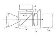
図11に、色分離結像光学系8の一実施例を示す。同図中、カメラレンズ7のあとにカラー画像撮影に使用する第2光源6からの可視光成分を含む光37を透過し、距離検出に使用する第1光源2からの可視領域外の光38を反射させるダイクロイックプリズム36を有する。このダイクロイックプリズム36のサイズと材質は、カメラレンズ7のバックフォーカス長を考慮し、高速撮像素子9にカメラレンズ7よりダイクロイックプリズム36を通して結像できる光路長となるように選択する。
【0061】
距離検出用の強度変調光源である第1光源2の出力光を近赤外光とした場合、ダイクロイックプリズム36による色分離特性は、可視光を透過し、近赤外光を反射する特性とする。第2光源6の波長を780nmから900nmの範囲を選択すれば、可視光の透過率を高く、しかも近赤外光の反射率を高く設計することができる。
【0062】
また、ダイクロイックプリズム36で反射した光成分に含まれる第1光源2の波長成分より長波長の光を除去する赤外透過の光学フィルタ39を配置することで、外光の影響を低減し、信号光である近赤外光のみを高速撮像素子9に入力できる特性が得られる。
【0063】
ダイクロイックプリズム36を通過した可視光はリレーレンズ40を通してカラーカメラ12に入力される。このリレーレンズ40の倍率はほぼ等倍であり、レンズにはフォーカス調整機能を備える。このとき、リレーレンズ40の構成をテレセントリック光学系とすることでフォーカス調整が容易となる。
【0064】
リレーレンズ40は、可視領域において、透過率や収差などの結像光学特性の最適化を行い、MTF(Modulation Transfer Function)の低下を押さえ、カメラレンズによる結像光学画像を高精細、かつ、画像の色変化や輝度の低下なくカラーカメラ12に伝達入力する。また、リレーレンズ40の開口数をカメラレンズ7と同等とすることで、明るさの低減を抑える。また、リレーレンズ40には絞り調整機構をもたせることで、距離検出側への近赤外光量に影響なく、カラー画像の絞り調整が可能となる。
【0065】
図12に、高速撮像素子9として、イメージインテンシファイア41とCCDカメラ42を用いた実施例を示す。同図中、ダイクロイックプリズム36で反射した第1光源2の光成分をイメージインテンシファイア41に結像入力する。イメージインテンシファイア41は、光電変換面43、マイクロチャンネルプレート(MCP)44、蛍光面45から構成されるものが使用できる。
【0066】
イメージインテンシファイア41の光電変換面43とMCP44間の印加電圧の値を制御することで、時間と共に撮像感度を高速に変化できる。また、印加電圧をパルス形状とすることで、1nsec以下の短時間のゲート撮像も可能となる。
【0067】
光電変換面43の材料は、距離検出に使用する強度変調光の波長感度特性により選択する。例えば、波長800nmの場合、マルチアルカリ材料(Sb−K−Na−Cs)が使用でき、更に長波長の850nmを使用する場合は、ガリウム砒素(GaAs)材料を使用することで高い量子効率が得られるため、S/Nのよい撮像画像が得られる。
【0068】
撮像ゲインを高速に変化させ、または短時間のゲート動作をさせて画像を撮像するため、1回の撮像で得られる信号量は非常に微弱であるため、強度変調光4の光源2の出力タイミングと撮像ゲイン変調タイミングを同期させ、繰り返し撮像し、イメージインテンシファイア41の出力蛍光面45の画像を画像伝達光学系46でCCDカメラ42に入力し、CCDカメラ42の蓄積効果で十分な感度を確保することができる。
【0069】
画像伝達光学系46はファイバプレートもしくはリレーレンズ光学系で実現できる。画像伝達光学系46をファイバプレートとし、イメージインテンシファイアの蛍光面45とCCDカメラ42のCCD面を連結するごとで、高い効率で蛍光面出力光をCCDカメラ42に入力できる。
【0070】
一方、リレーレンズの場合、フォーカス調整や画像位置の微調整機構を持たせることができる。リレーレンズの透過率や画像の結像収差特性は、イメージインテンシファイアの蛍光面45の蛍光波長で最適化する。リレーレンズを用いた場合、ファイバプレートを用いた場合より光の利用効率が下がるが、CCDカメラ42が交換でき、CCDカメラ42の選択の幅が広がるとともに、結像倍率の制御が可能であると共に、ファイバプレート使用時に発生する固定パターンノイズの影響がなく、良好な画像が得られる特徴がある。画像の結像倍率は、カラー画像の画角とCCDカメラ42で撮像する画角が同じになる倍率とする。
【0071】
イメージインテンシファイア41の撮像の解像度は、イメージインテンシファイア41を構成する光電変換面43とMCP44の間隔、MCP44と蛍光面45間の間隔、MCP44を構成する導電性のガラスキャピラリの直径に大きく依存する。そのため、光電変換面43とMCP44の間隔、MCP44と蛍光面45間の間隔を近接させると共に、MCPを構成する導電性のガラスキャピラリの直径を細かいものを使用すると高解像度に有利である。
【0072】
また、イメーイジンテシファイア41ヘの結像入力画像を拡大入力し、画像伝達光学系46で縮小しCDDカメラ42に入力することで解像度を高く保つことができる。CCDカメラ42としては、標準TV用カメラやハイビジョンカメラが使用できるとともに、その他産業用の高精細CCDカメラも使用できる。
【0073】
図13は、信号処理部10の一実施例のブロック図を示す。同図中、高速撮像素子9の出力信号は画角変換部47に供給され、所望の出力画像のアスペクト比に変換される。例えば、1300(H)×1030(V)のCCDを高速撮像素子9に使用した場合、ハイビジョン映像の距離画像を出力するときには、1画面の16:9の領域(例えば1280(H)×853(V))の信号を画角変換部47で抽出する。
【0074】
次に、光強度及び撮像パターンの異なるタイミングで撮像した信号を、外部同期48に同期したスイッチ49で切り換えて、それぞれメモリ50Aとメモリ50Bに記憶する。メモリ50A,50Bの記憶タイミングは外部同期48に同期して行われる。これにより、例えば光強度が増加する強度変調光の照射時に短時間撮像した被写体画像がメモリ50Aに記憶され、光強度が減少する強度変調光の照射時に短時間撮像した被写体画像がメモリ50Aに記憶される。
【0075】
メモリ50A,50Bから読み出された信号は信号調整回路51A,51Bにて画像の輝度調整や、画像全体にある一定の輝度レベルを付加するためのセットアップ調整を行われたのち、距離算出演算部53で(4)式、または(9)式、または(13)式の演算を行って距離dを算出し、距離を明暗で表す距離映像信号を得る。その後、距離映像信号は信号変換部54により所望のテレビジョン信号規格に変換されて出力される。
【0076】
図14は、本発明の3次元情報検出装置の第2実施例の構成図を示す。同図中、カメラレンズ7の周囲に配置されたLED(発光ダイオード)アレイ55より近赤外波長(中心波長850nm)の強度変調光を被写体1に照射する。また、蛍光灯56より可視光を被写体1に照射する。
【0077】
被写体1からの反射光の可視光成分は、カメラレンズ7の後に配置されたダイクロイックプリズム36を透過し、リレーレンズ40を通してカラーカメラ12に結像される。
【0078】
一方、LEDアレイ55からの近赤外光は、ダイクロイックプリズム36で反射され、高速撮像素子9側に入射される。高速撮像素子9では、高速シャッタ機能をもつイメージインテンシファイア41により短時間シャッタ撮影を行い、イメージインテンシファイア41出力の光画像をリレーレンズ46でCCDカメラ42へ入力する。
【0079】
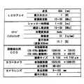
LEDアレイ55に供給する変調信号とイメージインテンシファイア41のシャッタトリガ信号は信号発生器57で同期して発生する。これにより、増加変調光照射時と減少変調光照射時の画像を交互に撮影する。CCDカメラ42の出力信号を信号処理部10に供給して距離算出を行い、距離を明暗で表す距離映像信号11をハイビジョン信号出力する。上記LEDアレイ55,イメージインテンシファイア41,CCDカメラ42,カラーカメラ12,カメラレンズ7それぞれの仕様を図15に示す。
【0080】
また、図16に、カラーカメラ12側への光透過率と、距離検出側(高速撮像素子9側)への光透過率、及び蛍光灯56出力の可視光とLEDアレイ55出力の近赤外光の出力スペクトルを示す。ダイクロイックプリズム36により、可視光成分と距離検出用の近赤外光成分が、高効率で分割されている。距離検出側への近赤外光の透過率が高いため、距離検出に十分な感度があり、S/Nのよい良好な距離検出が可能となっている。
【0081】
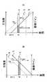
白紙を被写体1とし、カメラレンズ7からの距離を変化させ、距離映像信号11のレベルを測定した。このときの強度変調光の変調周波数は15MHz、撮像時間幅は5nsec(半値幅)、測定中心位置を6mに設定した。その結果、図17に示すように、カメラレンズ7から被写体1までの距離とともに、距離映像信号レベルが変化し、距離に応じた明暗映像が得られる。また、測定中心の6m付近では、比較的リニアな特性を有しているが、測定範囲の周辺部で非線型性が生じている。これはLEDの光変調特性の非線型成分の影響であり、出力信号のγ補正によりリニアな特性に補正できる。
【0082】
本実施例における距離検出範囲は15MHzで約4mであった。被写体1の奥行きがより小さい場合、変調周波数を45MHzと高くすることで奥行き検出範囲は約1.5mとなり、相対的に奥行き検出分解能を高めることができる。
【0083】
また、距離映像信号のノイズ成分量より、距離検出分解能を評価した。測定は強度変調光4の周波数を45MHz、撮像時間幅を2nsとして、カメラレンズ7から被写体1までの距離を1m〜10mまで変化させ、距離映像信号のノイズ成分の実効値σを測定し、3×σに相当する距離の値を距離検出分解能とした場合の距離と距離検出分解能の関係を図18に示す。被写体1がカメラレンズ7より2mの位置にあるとき、距離映像信号のS/Nは44.4dBであり、距離検出分解能は1.7cmであった。
【0084】
本発明では、カラー画像とともに、高速かつ高精細な距離画像を取得できる3次元情報検出方法及び装置を示した。撮影光軸と光照射光軸を近接もしくは一致させることで、光照射の影を低減し撮影画角全体の距離を検出することが可能となる。更に、強度変調光または撮像ゲインの変調特性の組合せにより、簡易な演算処理で高速に距離を算出でき、動画像に対しても距離を算出できることが可能となった。
【0085】
また、カメラレンズのあとに色分離結像光学系を導入し、カラー画像と距離画像を同じ画角で、標準のTV画像やハイビジョンクラスの高精細な画像の距離画像をビデオレートで撮影できるとともに、カメラレンズのズーム機能にも対応した3次元情報の検出が可能となる。
【0086】
本発明装置は、被写体のカラー画像と共に奥行き距離情報が取得できる3次元カメラとして各分野に応用できる。その一例として、テレビジョン放送用カメラとしては、距離情報を基にした画像の抽出や合成など、また、立体テレビジョン用のカメラとしても適用できる。更に、3次元モデリング、医療診断、自動車や航空、宇宙、船舶分野におけるエンジン等の機器内の観察や、ガス管、排気口、水道管、ボイラー、タービン内の検査、古墳や遺跡内の調査や動物生態の観察などの分野に適用できる。
【0087】
なお、第1光源2,光照射光学系3が請求項記載の第1光照射手段に対応し、第2光源6が第2光照射手段に対応し、色分離結像光学系8が光分離手段に対応し、高速撮像素子9がゲイン可変撮像手段に対応し、カラーカメラ12が撮影手段に対応し、信号処理部10が信号処理手段に対応し、ハーフミラー17,偏光ビームスプリッタ19が光軸一致手段に対応する。
【0088】
【発明の効果】
上述の如く、請求項1,2に記載の発明によれば、高精細な画像の距離映像をビデオレートで取得でき、カメラレンズのズーム機能に対応したカラー映像と距離映像を取得することができる。
【0089】
請求項3に記載の発明によれば、カメラレンズのズーム機能に対応したカラー映像と距離映像を取得することができる。
【0090】
請求項4に記載の発明によれば、可視領域外の光照射で発生する影を小さくして、被写体において距離検出ができない部分を縮小できる。
【0091】
請求項5に記載の発明によれば、可視領域外の光照射で発生する影をなくし、被写体において距離検出ができない部分をなくすことができる。
【図面の簡単な説明】
【図1】本発明の3次元情報検出装置の第1実施例の構成図である。
【図2】第1光源及び光照射光学系の配置の一実施例を示す図である。
【図3】カメラレンズの両脇に光源を配置した実施例を示す図である。
【図4】カメラレンズの両脇に光源を配置した実施例を示す図である。
【図5】撮影光軸と照射光軸を一致させる方法を示す図である。
【図6】撮影光軸と照射光軸を一致させる方法を示す図である。
【図7】光照射光学系の一実施例を示す図である。
【図8】パルス状の撮像ゲインと光強度が増加および減少する強度変調光による距離検出方法を説明するための図である。
【図9】パルス状の強度変調光と光強度が増加および減少する撮像ゲインによる距離検出方法を説明するための図である。
【図10】パルス状の強度変調光とパルス状の撮像ゲインによる距離検出方法を説明するための図である。
【図11】色分離結像光学系の一実施例を示す図である。
【図12】高速撮像素子としてイメージインテンシファイアとCCDカメラを用いた実施例を示す図である。
【図13】信号処理部の一実施例のブロック図である。
【図14】本発明の3次元情報検出装置の第2実施例の構成図である。
【図15】LEDアレイ,イメージインテンシファイア,CCDカメラ,カラーカメラ,カメラレンズの仕様を示す図である。
【図16】透過率と、光源光出力スペクトルを示す図である。
【図17】距離と距離映像信号レベルの関係を示す図である。
【図18】距離と距離検出分解能の関係を示す図である。
【符号の説明】
1 被写体
2 第1光源
3 光照射光学系
4 強度変調光
5 可視光
6 第2光源
7 カメラレンズ
8 色分離結像光学系
9 高速撮像素子
10 信号処理部
11 距離映像信号
12 カラーカメラ
13 カラー映像信号
14 撮影光軸
15 光照射光軸
16 影
17 ハーフミラー
18 遮光体
19 偏光ビームスプリッタ
20 λ/4板
21 レンズ
22 拡散板
23,26 強度変調光
24,27,29,33 反射光
25 パルス状撮像ゲイン
28 パルス光
30,31,34,35 撮像ゲイン
32 強度変調光
36 ダイクロイックプリズム
37 可視光成分を含む光
38 可視領域外の光
39 光学フィルタ
40 リレーレンズ
41 イメージインテンシファイア
42 CCDカメラ
43 光電変換面
44 マイクロチャンネルプレート
45 蛍光面
46 画像伝達光学系
47 画角変換部
48 外部同期
49 スイッチ
50A,50B メモリ
51A,51B 信号調整回路
53 距離算出演算部
54 信号変換部
55 LEDアレイ
56 蛍光灯
57 信号発生器[0001]
TECHNICAL FIELD OF THE INVENTION
The present invention relates to a method and an apparatus for detecting three-dimensional information, and more particularly to a method and an apparatus for detecting three-dimensional information for detecting a depth shape of a subject and acquiring three-dimensional information.
[0002]
[Prior art]
As a method of detecting a three-dimensional position or a depth distance of an object, there is a stereo method of acquiring three-dimensional information from a multi-viewpoint image obtained by using a plurality of cameras. Further, as a method of irradiating light and detecting a distance, there is a method of calculating a distance by sine-wave driving the irradiating light and detecting a phase on a reflection side.
[0003]
Further, Japanese Patent Application No. 10-293817 describes that a distance is calculated faster than two images taken by selecting two combinations of a time change of irradiation light and a gain modulation on an imaging side. ing.
[0004]
[Problems to be solved by the invention]
The method of acquiring three-dimensional information by the stereo method does not need to irradiate light, so there is an advantage that it is not affected by external light, but on the other hand, the arrangement of a plurality of cameras and the calibration of camera lenses are complicated, Also, the device is large and lacks versatility. Furthermore, the photographing angle of view cannot be freely changed by the zoom operation of the camera lens. Furthermore, in a high-definition image equal to or larger than a standard television image, calculating a distance for each pixel requires time for image matching processing for searching for a corresponding point between a plurality of images, so that a video rate (frame rate of 60 Hz) is required. There is a problem that it is difficult to detect a large number of pixels of 400,000 pixels or more at such a high speed.
[0005]
In the method of irradiating a sine-wave light to a subject and detecting its phase on the reflection side, it is necessary to calculate the phase of light for each photographing pixel. In the case of detecting the entire distance, a two-dimensional scanning mechanism of the light beam is required, so that there is a problem that high-speed performance is impaired and the configuration becomes complicated.
[0006]
Also, Japanese Patent Application No. 10-293817 discloses a method of acquiring a distance image (an image in which distance information is represented by the luminance of an image signal) at high speed. However, a distance image having the same angle of view as a color image is obtained. Simultaneous shooting, no occlusion of distance detection, enabling high-definition video class high-quality video shooting, taking into account the specific method of linking color images and distance images according to the zoom function of the camera lens There was a problem that was not.
[0007]
SUMMARY OF THE INVENTION The present invention has been made in view of the above points, and can obtain a high-definition image of a distance image at a video rate, and can obtain a color image and a distance image corresponding to a zoom function of a camera lens. It is an object to provide a detection method and device.
[0008]
[Means for Solving the Problems]
The invention according to
The reflected light from the subject collected by the camera lens is wavelength-separated into light outside the visible region and light in the visible region,
Modulating the imaging gain to capture an optical image outside the visible region separated by the wavelength,
The optical signal of the wavelength-separated visible region is captured and a video signal is output,
Calculate the distance from the intensity ratio between a plurality of images obtained by capturing the optical image outside the visible region when the time variation pattern between the intensity modulation of the light outside the visible region and the modulation of the imaging gain is a different combination, By outputting a distance video signal that represents the distance with light and dark,
A high-definition distance image can be obtained at a video rate, and a color image and a distance image corresponding to a zoom function of a camera lens can be obtained.
[0009]
According to a third aspect of the present invention, in the three-dimensional information detecting device according to the second aspect,
The camera lens has a zoom function,
After zooming with the camera lens, the wavelength is separated into light outside the visible region and light in the visible region, so that a color image and a distance image corresponding to the zoom function of the camera lens can be obtained.
[0010]
According to a fourth aspect of the present invention, in the three-dimensional information detecting device according to the second or third aspect,
The first light irradiating means is arranged around the camera lens such that the optical axis of light outside the visible region to be irradiated is close to the optical axis of the camera lens,
Shadows generated by light irradiation outside the visible region can be reduced, and portions of the subject where distance detection is not possible can be reduced.
[0011]
According to a fifth aspect of the present invention, in the three-dimensional information detecting device according to the second or third aspect,
By having an optical axis matching unit that matches an optical axis of light outside the visible region irradiated by the first light irradiation unit with an optical axis of the camera lens,
Shadows generated by light irradiation outside the visible region can be eliminated, and a portion of the subject where distance detection cannot be performed can be eliminated.
[0012]
BEST MODE FOR CARRYING OUT THE INVENTION
FIG. 1 is a configuration diagram of a first embodiment of a three-dimensional information detecting device according to the present invention. In the figure, the output light of the
[0013]
Further, the wavelength of the output light of the
It is easy to manufacture an optical system that ensures an optically high color separation and imaging optical system ratio.
[0014]
The means for generating the intensity modulated
[0015]
Further, as the light irradiation
[0016]
The
[0017]
The reflected light from the subject 1 illuminated by the first
[0018]
A color separation / imaging
[0019]
The high-speed imaging device 9 modulates the imaging gain and captures a plurality of images under the condition that the intensity-modulated light of the first
[0020]
On the other hand, the formed image of the light component from the second
[0021]
FIG. 2 shows an embodiment of the arrangement of the first
[0022]
Δl = l · Δd / d (1)
As is apparent from the expression (1), the shadow area can be reduced as the distance l between the photographing optical axis 14 of the
[0023]
FIG. 3 shows an embodiment in which light sources are arranged on both sides of the
[0024]
Further, in FIG. 3, a portion which becomes a
[0025]
As shown in FIG. 4, there are
[0026]
FIG. 5 shows a method for matching the photographing optical axis with the irradiation optical axis. In the figure, a half mirror 17 is arranged in front of the
[0027]
Thereby, the
[0028]
Further, a
[0029]
The output light passes through the λ / 4
[0030]
On the other hand, since a part of the output light from the first
[0031]
Incidentally, the irradiation angle of the irradiation light is controlled by a light irradiation
[0032]
At this time, the light irradiation
[0033]
For example, when a standard television camera is used, the aspect ratio is 4: 3, and when high-definition shooting is performed, the aspect ratio is 16: 9. Further, a diffusion plate 22 can be used for the light irradiation
[0034]
In particular, with respect to a diffusion plate using surface diffraction, the light distribution shape and intensity distribution of light can be controlled by the pattern of the unevenness on the surface, so that illumination with good uniformity can be realized efficiently according to the angle of view of the image.
[0035]
Here, a description will be given of a light whose intensity increases and decreases with time as intensity-modulated light, and a distance detection method using an imaging device having a short-time shutter function. As shown in FIG. 8A, a subject placed at a distance d is irradiated with intensity-modulated
[0036]
(Equation 1)
[0037]
Next, as shown in FIG. 8B, an intensity-modulated
[0038]
(Equation 2)
[0039]
From the expressions (2) and (3), the intensity ratio R = E between two images having different light intensities is obtained.+ / E− , And the distance d is obtained, the expression (4) is obtained.
[0040]
[Equation 3]
[0041]
As described above, since a light source whose intensity changes with time can be realized even at a frequency as low as several tens of MHz, in addition to a laser light source, incoherent illumination such as an LED (light emitting diode) can be used, and a wide range can be illuminated with high luminance. It is also possible to detect the distance of a person. Note that the range of distance detection by this method is determined by the imaging time ts and the modulation frequency f, and is expressed by equation (5).
[0042]
(Equation 4)
[0043]
dr = C / 4f (6)
Measurement range dr Is 7.5 m, the modulation frequency f is 10 MHz, and the measurement range dr Is 1.5 m, the modulation frequency f is 50 MHz. On the other hand, the imaging time width Δt at the time of imaging is shorter than the
[0044]
Next, a short-time pulse light is used as the intensity-modulated light, and an image captured while increasing the imaging gain of the high-speed imaging device 9 with time at high speed and an image captured with the imaging gain reduced at high speed with time are used. A method for calculating the distance and detecting the distance will be described.
[0045]
As shown in FIG. 9A, the light intensity F is applied to the subject 1 at the position of the distance d.0 At the time tp, and the amount of signal E detected by the camera when the reflected light 29 from the
[0046]
(Equation 5)
[0047]
Next, as shown in FIG. 9B, the signal amount E detected by the camera when the image is captured by the high-speed imaging device 9 having the
[0048]
(Equation 6)
[0049]
From the equations (7) and (8), the intensity ratio R = E between two images having different imaging gains is obtained.+ / E− , And the distance d is obtained, the expression (9) is obtained.
[0050]
(Equation 7)
[0051]
As described above, a pulse laser can be used in the combination of the pulsed light and the imaging gain that changes with time, and a pulse laser light having a pulse width of picosecond to femtosecond, such as a Q-switched pulse laser light or a mode-locked pulse light. Can be used, so that distance detection with high resolution can be performed.
[0052]
In this case, the measurable range (measurement range) D is represented by equation (10).
[0053]
(Equation 8)
[0054]
(Equation 9)
[0055]
Next, as shown in FIG. 10B, when imaging is performed with a rectangular imaging gain 35 (gain g, period T) having a phase opposite to that of the intensity-modulated
[0056]
(Equation 10)
[0057]
From the expressions (11) and (12), the intensity ratio R = E between the two images is obtained.+ / E− , And the distance d is obtained, the expression (13) is obtained.
[0058]
[Equation 11]
[0059]
In this manner, by making the intensity modulation irradiation light and the imaging gain into a rectangular wave shape having the same cycle width, the amount of detection signals detected by the imaging element increases, and imaging with a high signal-to-noise ratio can be performed. High-resolution distance detection becomes possible.
[0060]
FIG. 11 shows one embodiment of the color separation / imaging
[0061]
When the output light of the first
[0062]
Further, by disposing an infrared transmitting
[0063]
The visible light passing through the
[0064]
The
[0065]
FIG. 12 shows an embodiment using an
[0066]
By controlling the value of the applied voltage between the
[0067]
The material of the
[0068]
Since an image is captured by changing the imaging gain at a high speed or by performing a gate operation for a short time, the signal amount obtained by one imaging is very weak. And the imaging gain modulation timing is synchronized, images are repeatedly taken, and the image of the
[0069]
The image transmission
[0070]
On the other hand, in the case of a relay lens, a mechanism for fine adjustment of focus and image position can be provided. The transmittance of the relay lens and the imaging aberration characteristics of the image are optimized by the fluorescent wavelength of the
[0071]
The imaging resolution of the
[0072]
Further, the resolution can be kept high by enlarging and inputting the image input to the
[0073]
FIG. 13 shows a block diagram of one embodiment of the
[0074]
Next, the signals captured at different timings of the light intensity and the imaging pattern are switched by the
[0075]
The signals read from the
[0076]
FIG. 14 is a configuration diagram of a second embodiment of the three-dimensional information detecting apparatus according to the present invention. In the figure, a
[0077]
The visible light component of the reflected light from the subject 1 passes through the
[0078]
On the other hand, the near-infrared light from the
[0079]
The modulation signal supplied to the
[0080]
FIG. 16 shows the light transmittance to the
[0081]
The level of the distance video signal 11 was measured while changing the distance from the
[0082]
The distance detection range in this embodiment was about 4 m at 15 MHz. When the depth of the subject 1 is smaller, the depth detection range becomes about 1.5 m by increasing the modulation frequency to 45 MHz, and the depth detection resolution can be relatively increased.
[0083]
Further, the distance detection resolution was evaluated based on the noise component amount of the distance video signal. The measurement was performed with the frequency of the intensity modulated
[0084]
In the present invention, a three-dimensional information detection method and apparatus capable of acquiring a high-speed and high-resolution range image together with a color image has been described. By bringing the photographing optical axis close to or coincident with the light irradiation optical axis, it is possible to reduce the shadow of light irradiation and detect the distance of the entire photographing angle of view. Further, the combination of the intensity modulation light and the modulation characteristic of the imaging gain makes it possible to calculate the distance at high speed with simple arithmetic processing, and to calculate the distance even for a moving image.
[0085]
In addition, a color-separation imaging optical system is introduced after the camera lens so that color images and distance images can be captured at the same angle of view, and standard TV images and high-definition class high-definition images can be captured at video rates. This makes it possible to detect three-dimensional information corresponding to the zoom function of the camera lens.
[0086]
The device of the present invention can be applied to various fields as a three-dimensional camera capable of acquiring depth distance information together with a color image of a subject. For example, as a television broadcast camera, an image can be extracted or synthesized based on distance information, and can also be applied as a stereoscopic television camera. In addition, three-dimensional modeling, medical diagnosis, observation of equipment such as engines in the automobile, aviation, space, and marine fields, inspection of gas pipes, exhaust ports, water pipes, boilers, turbines, and investigation of tumuli and archeological sites Applicable to fields such as observation of animal ecology.
[0087]
The first
[0088]
【The invention's effect】
As described above, according to the first and second aspects of the present invention, it is possible to obtain a distance image of a high-definition image at a video rate, and to obtain a color image and a distance image corresponding to a zoom function of a camera lens. .
[0089]
According to the third aspect of the invention, a color image and a distance image corresponding to the zoom function of the camera lens can be obtained.
[0090]
According to the fourth aspect of the present invention, it is possible to reduce a shadow generated by light irradiation outside the visible region and to reduce a portion of the subject where distance detection is not possible.
[0091]
According to the fifth aspect of the present invention, it is possible to eliminate a shadow generated by light irradiation outside the visible region and eliminate a portion of the subject where distance detection is not possible.
[Brief description of the drawings]
FIG. 1 is a configuration diagram of a first embodiment of a three-dimensional information detection device of the present invention.
FIG. 2 is a diagram showing an embodiment of an arrangement of a first light source and a light irradiation optical system.
FIG. 3 is a diagram showing an embodiment in which light sources are arranged on both sides of a camera lens.
FIG. 4 is a diagram showing an embodiment in which light sources are arranged on both sides of a camera lens.
FIG. 5 is a diagram illustrating a method of matching an imaging optical axis with an irradiation optical axis.
FIG. 6 is a diagram showing a method of matching an imaging optical axis with an irradiation optical axis.
FIG. 7 is a diagram showing one embodiment of a light irradiation optical system.
FIG. 8 is a diagram for explaining a distance detection method using pulse-shaped imaging gain and intensity-modulated light whose light intensity increases and decreases.
FIG. 9 is a diagram for explaining a distance detection method using pulse-like intensity modulated light and an imaging gain in which light intensity increases and decreases.
FIG. 10 is a diagram for explaining a distance detection method using pulse-like intensity-modulated light and pulse-like imaging gain.
FIG. 11 is a diagram showing one embodiment of a color separation and imaging optical system.
FIG. 12 is a diagram showing an embodiment using an image intensifier and a CCD camera as a high-speed imaging device.
FIG. 13 is a block diagram of one embodiment of a signal processing unit.
FIG. 14 is a configuration diagram of a second embodiment of the three-dimensional information detection device of the present invention.
FIG. 15 is a diagram showing specifications of an LED array, an image intensifier, a CCD camera, a color camera, and a camera lens.
FIG. 16 is a diagram showing transmittance and a light source light output spectrum.
FIG. 17 is a diagram illustrating a relationship between a distance and a distance video signal level.
FIG. 18 is a diagram illustrating a relationship between a distance and a distance detection resolution.
[Explanation of symbols]
1 subject
2 First light source
3 Light irradiation optical system
4 Intensity modulated light
5 Visible light
6 Second light source
7 Camera lens
8 color separation and imaging optical system
9 High-speed image sensor
10 Signal processing unit
11 Distance video signal
12 color camera
13 color video signal
14 Shooting optical axis
15 Light irradiation optical axis
16 Shadow
17 Half mirror
18 Shade
19 Polarizing beam splitter
20 λ / 4 plate
21 lenses
22 Diffusion plate
23,26 intensity modulated light
24, 27, 29, 33 reflected light
25 Pulse imaging gain
28 pulsed light
30, 31, 34, 35 Imaging gain
32 intensity modulated light
36 dichroic prism
37 Light containing visible light components
38 Light outside the visible range
39 Optical Filter
40 relay lens
41 Image Intensifier
42 CCD camera
43 Photoelectric conversion surface
44 micro channel plate
45 phosphor screen
46 Image transmission optical system
47 Angle of view converter
48 External synchronization
49 switch
50A, 50B memory
51A, 51B signal adjustment circuit
53 Distance calculation unit
54 signal converter
55 LED array
56 fluorescent light
57 signal generator
Claims (9)
Translated fromJapaneseカメラレンズで集光された前記被写体からの反射光を可視領域外の光と可視領域の光とに波長分離し、
撮像ゲインを変調して前記波長分離された可視領域外の光学像を撮像し、
前記波長分離された可視領域の光学像を撮影し映像信号を出力し、
前記可視領域外の光の強度変調と前記撮像ゲインの変調との時間変化パターンが異なる組合せであるときに前記可視領域外の光学像を撮像した複数の画像間の強度比から距離を算出し、距離を明暗で表す距離映像信号を出力することを特徴とする3次元情報検出方法。Irradiating the subject with intensity modulated light outside the visible region and irradiating the subject with light in the visible region,
The reflected light from the subject collected by the camera lens is wavelength-separated into light outside the visible region and light in the visible region,
Modulating the imaging gain to capture an optical image outside the visible region separated by the wavelength,
The optical signal of the wavelength-separated visible region is captured and a video signal is output,
Calculate the distance from the intensity ratio between a plurality of images obtained by capturing the optical image outside the visible region when the time variation pattern between the intensity modulation of the light outside the visible region and the modulation of the imaging gain is a different combination, A three-dimensional information detection method, comprising: outputting a distance video signal representing a distance with light and dark.
可視領域の光を前記被写体に照射する第2光照射手段と、
前記被写体からの反射光を集光するカメラレンズと、
前記カメラレンズで集光された光を可視領域外の光と可視領域の光とに波長分離する光分離手段と、
撮像ゲインを変調して前記光分離手段で波長分離された可視領域外の光学像を撮像するゲイン可変撮像手段と、
前記光分離手段で分離された可視領域の光学像を撮影し映像信号を出力する撮影手段と、
前記第1光照射手段の出力光の強度変調と前記ゲイン可変撮像手段の撮像ゲインの変調との時間変化パターンが異なる組合せであるときに前記ゲイン可変撮像手段で撮像した複数の画像間の強度比から距離を算出し、距離を明暗で表す距離映像信号を出力する信号処理手段とを
有することを特徴とする3次元情報検出装置。First light irradiation means for modulating the intensity of light outside the visible region and irradiating the object with light;
Second light irradiating means for irradiating the subject with light in a visible region;
A camera lens for collecting reflected light from the subject,
Light separating means for wavelength-separating the light collected by the camera lens into light outside the visible region and light in the visible region,
A variable gain imaging unit that modulates an imaging gain and captures an optical image outside the visible region wavelength-separated by the light separation unit,
A photographing means for photographing an optical image in a visible region separated by the light separating means and outputting a video signal,
The intensity ratio between a plurality of images captured by the variable gain imaging unit when the time variation patterns of the intensity modulation of the output light of the first light irradiation unit and the modulation of the imaging gain of the variable gain imaging unit are different combinations. A signal processing means for calculating a distance from the distance and outputting a distance video signal representing the distance in light and dark.
前記カメラレンズは、ズーム機能を有することを特徴とする3次元情報検出装置。The three-dimensional information detection device according to claim 2,
The three-dimensional information detection device, wherein the camera lens has a zoom function.
前記第1光照射手段は、照射する可視領域外の光の光軸が前記カメラレンズの光軸に近接するよう、前記カメラレンズの周囲に配置したことを特徴とする3次元情報検出装置。The three-dimensional information detection device according to claim 2 or 3,
The three-dimensional information detecting device according to claim 1, wherein the first light irradiating means is arranged around the camera lens such that an optical axis of light to be irradiated outside a visible region is close to an optical axis of the camera lens.
前記第1光照射手段が照射する可視領域外の光の光軸を前記カメラレンズの光軸に一致させる光軸一致手段を
有することを特徴とする3次元情報検出装置。The three-dimensional information detection device according to claim 2 or 3,
3. A three-dimensional information detecting apparatus, comprising: an optical axis matching unit that matches an optical axis of light out of a visible region emitted by the first light emitting unit with an optical axis of the camera lens.
前記第1光照射手段は、前記可視領域外の光の光強度を時間と共に増加及び減少させて出力し、
前記ゲイン可変撮像手段は、前記撮像ゲインをパルス状に短時間一定値とし、
前記信号処理手段は、前記光強度を時間と共に増加させながら撮像した画像と前記光強度を時間と共に減少させながら撮像した画像との間の強度比から距離を算出することを特徴とする3次元情報検出装置。The three-dimensional information detection device according to any one of claims 2 to 5,
The first light irradiation unit increases and decreases the light intensity of the light outside the visible region with time, and outputs the light intensity.
The gain-variable imaging unit sets the imaging gain to a pulse-like constant value for a short time,
The three-dimensional information, wherein the signal processing unit calculates a distance from an intensity ratio between an image captured while increasing the light intensity with time and an image captured while decreasing the light intensity with time. Detection device.
前記第1光照射手段は、前記可視領域外のパルス光を出力し、
前記ゲイン可変撮像手段は、前記撮像ゲインを時間と共に増加及び減少させ、
前記信号処理手段は、前記撮像ゲインを時間と共に増加させながら撮像した画像と前記撮像ゲインを時間と共に減少させながら撮像した画像との間の強度比から距離を算出することを特徴とする3次元情報検出装置。The three-dimensional information detection device according to any one of claims 2 to 5,
The first light irradiating means outputs pulsed light outside the visible region,
The variable gain imaging means increases and decreases the imaging gain with time,
The three-dimensional information, wherein the signal processing means calculates a distance from an intensity ratio between an image captured while increasing the imaging gain with time and an image captured while decreasing the imaging gain with time. Detection device.
前記第1光照射手段は、前記可視領域外の光の光強度を矩形波状に変調して出力し、
前記ゲイン可変撮像手段は、前記撮像ゲインを前記光強度と同一周期で矩形波状に変調し、
前記信号処理手段は、前記光強度と前記撮像ゲインが同位相のとき撮像した画像と前記光強度と前記撮像ゲインが逆位相のとき撮像した画像との間の強度比から距離を算出することを特徴とする3次元情報検出装置。The three-dimensional information detection device according to any one of claims 2 to 5,
The first light irradiation means modulates the light intensity of the light outside the visible region into a rectangular wave and outputs the modulated light intensity.
The gain variable imaging unit modulates the imaging gain into a rectangular wave at the same cycle as the light intensity,
The signal processing unit calculates a distance from an intensity ratio between an image captured when the light intensity and the imaging gain are in phase and an image captured when the light intensity and the imaging gain are in opposite phase. Characteristic three-dimensional information detection device.
前記ゲイン可変撮像手段は、イメージインテンシファイアとCCDカメラからなることを特徴とする3次元情報検出装置。The three-dimensional information detection device according to any one of claims 2 to 8,
3. The three-dimensional information detecting device according to claim 1, wherein said variable gain imaging means comprises an image intensifier and a CCD camera.
Priority Applications (1)
| Application Number | Priority Date | Filing Date | Title |
|---|---|---|---|
| JP2002204189AJP4031306B2 (en) | 2002-07-12 | 2002-07-12 | 3D information detection system |
Applications Claiming Priority (1)
| Application Number | Priority Date | Filing Date | Title |
|---|---|---|---|
| JP2002204189AJP4031306B2 (en) | 2002-07-12 | 2002-07-12 | 3D information detection system |
Publications (2)
| Publication Number | Publication Date |
|---|---|
| JP2004045266Atrue JP2004045266A (en) | 2004-02-12 |
| JP4031306B2 JP4031306B2 (en) | 2008-01-09 |
Family
ID=31709855
Family Applications (1)
| Application Number | Title | Priority Date | Filing Date |
|---|---|---|---|
| JP2002204189AExpired - Fee RelatedJP4031306B2 (en) | 2002-07-12 | 2002-07-12 | 3D information detection system |
Country Status (1)
| Country | Link |
|---|---|
| JP (1) | JP4031306B2 (en) |
Cited By (22)
| Publication number | Priority date | Publication date | Assignee | Title |
|---|---|---|---|---|
| JP2006179424A (en)* | 2004-12-24 | 2006-07-06 | Toyota Motor Corp | Battery manufacturing method |
| JP2006201037A (en)* | 2005-01-20 | 2006-08-03 | Ricoh Co Ltd | Shape measuring device |
| JP2008249431A (en)* | 2007-03-29 | 2008-10-16 | Nippon Hoso Kyokai <Nhk> | 3D image correction method and apparatus |
| JP2009300268A (en)* | 2008-06-13 | 2009-12-24 | Nippon Hoso Kyokai <Nhk> | Three-dimensional information detection device |
| JP2011007616A (en)* | 2009-06-25 | 2011-01-13 | Honda Motor Co Ltd | Three-dimensional shape measurement system |
| JP2011013104A (en)* | 2009-07-02 | 2011-01-20 | Honda Motor Co Ltd | Three-dimensional shape measurement apparatus |
| JP2011022034A (en)* | 2009-07-16 | 2011-02-03 | Honda Motor Co Ltd | Three-dimensional shape measuring system and three-dimensional shape measuring method |
| JP2011069965A (en)* | 2009-09-25 | 2011-04-07 | Japan Atomic Energy Agency | Image capturing apparatus, image display method, and recording medium with image display program recorded thereon |
| US8026971B2 (en) | 2006-05-18 | 2011-09-27 | Nippon Hoso Kyokai | Visible and infrared light image-taking optical system |
| CN103080984A (en)* | 2010-06-30 | 2013-05-01 | 巴里·林恩·詹金斯 | Systems and methods for determining from-region visibility and incremental PVS-based content stream processing using conservative linearized umbral event surfaces |
| US9892546B2 (en) | 2010-06-30 | 2018-02-13 | Primal Space Systems, Inc. | Pursuit path camera model method and system |
| US9916763B2 (en) | 2010-06-30 | 2018-03-13 | Primal Space Systems, Inc. | Visibility event navigation method and system |
| CN110057301A (en)* | 2019-04-29 | 2019-07-26 | 慧眼自动化科技(广州)有限公司 | A kind of height detecting device and detection method based on binocular 3D parallax |
| CN110310963A (en)* | 2018-03-27 | 2019-10-08 | 恒景科技股份有限公司 | System for adjusting light source power |
| CN112066907A (en)* | 2019-06-11 | 2020-12-11 | 深圳市光鉴科技有限公司 | Depth imaging device |
| CN112068144A (en)* | 2019-06-11 | 2020-12-11 | 深圳市光鉴科技有限公司 | Light projection system and 3D imaging device |
| JP2021121120A (en)* | 2016-05-11 | 2021-08-19 | パナソニックIpマネジメント株式会社 | Imaging device, imaging system and photodetection method |
| CN113325425A (en)* | 2021-06-25 | 2021-08-31 | 湖南友哲科技有限公司 | Method for detecting existence of test tube and test tube detection device |
| CN113820870A (en)* | 2020-06-19 | 2021-12-21 | 三赢科技(深圳)有限公司 | Projection module, imaging module and electronic device |
| WO2022002414A1 (en)* | 2020-07-03 | 2022-01-06 | Supsi (Scuola Universitaria Professionale Della Svizzera Italiana) | 3d image acquisition system for optical inspection and method for optical inspection of objects, in particular electronic assemblies, electronic boards and the like |
| CN114323313A (en)* | 2021-12-24 | 2022-04-12 | 北京深测科技有限公司 | Imaging method and system based on ICCD camera |
| JP2023007049A (en)* | 2021-07-01 | 2023-01-18 | 株式会社ダイフク | Inspection device and coating device provided with the same |
- 2002
- 2002-07-12JPJP2002204189Apatent/JP4031306B2/ennot_activeExpired - Fee Related
Cited By (30)
| Publication number | Priority date | Publication date | Assignee | Title |
|---|---|---|---|---|
| JP2006179424A (en)* | 2004-12-24 | 2006-07-06 | Toyota Motor Corp | Battery manufacturing method |
| JP2006201037A (en)* | 2005-01-20 | 2006-08-03 | Ricoh Co Ltd | Shape measuring device |
| US8026971B2 (en) | 2006-05-18 | 2011-09-27 | Nippon Hoso Kyokai | Visible and infrared light image-taking optical system |
| JP2008249431A (en)* | 2007-03-29 | 2008-10-16 | Nippon Hoso Kyokai <Nhk> | 3D image correction method and apparatus |
| JP2009300268A (en)* | 2008-06-13 | 2009-12-24 | Nippon Hoso Kyokai <Nhk> | Three-dimensional information detection device |
| JP2011007616A (en)* | 2009-06-25 | 2011-01-13 | Honda Motor Co Ltd | Three-dimensional shape measurement system |
| JP2011013104A (en)* | 2009-07-02 | 2011-01-20 | Honda Motor Co Ltd | Three-dimensional shape measurement apparatus |
| JP2011022034A (en)* | 2009-07-16 | 2011-02-03 | Honda Motor Co Ltd | Three-dimensional shape measuring system and three-dimensional shape measuring method |
| JP2011069965A (en)* | 2009-09-25 | 2011-04-07 | Japan Atomic Energy Agency | Image capturing apparatus, image display method, and recording medium with image display program recorded thereon |
| CN103080984A (en)* | 2010-06-30 | 2013-05-01 | 巴里·林恩·詹金斯 | Systems and methods for determining from-region visibility and incremental PVS-based content stream processing using conservative linearized umbral event surfaces |
| US9472019B2 (en) | 2010-06-30 | 2016-10-18 | Primal Space Systems, Inc. | System and method of from-region visibility determination and delta-PVS based content streaming using conservative linearized umbral event surfaces |
| CN103080984B (en)* | 2010-06-30 | 2017-04-12 | 巴里·林恩·詹金斯 | Method and system for determining a set of mesh polygons or segments of said mesh polygons that are visible from a viewport |
| US9892546B2 (en) | 2010-06-30 | 2018-02-13 | Primal Space Systems, Inc. | Pursuit path camera model method and system |
| US9916763B2 (en) | 2010-06-30 | 2018-03-13 | Primal Space Systems, Inc. | Visibility event navigation method and system |
| JP2021121120A (en)* | 2016-05-11 | 2021-08-19 | パナソニックIpマネジメント株式会社 | Imaging device, imaging system and photodetection method |
| JP7108888B2 (en) | 2016-05-11 | 2022-07-29 | パナソニックIpマネジメント株式会社 | IMAGING DEVICE, IMAGING SYSTEM AND LIGHT DETECTION METHOD |
| CN110310963A (en)* | 2018-03-27 | 2019-10-08 | 恒景科技股份有限公司 | System for adjusting light source power |
| CN110057301A (en)* | 2019-04-29 | 2019-07-26 | 慧眼自动化科技(广州)有限公司 | A kind of height detecting device and detection method based on binocular 3D parallax |
| CN112068144A (en)* | 2019-06-11 | 2020-12-11 | 深圳市光鉴科技有限公司 | Light projection system and 3D imaging device |
| CN112066907A (en)* | 2019-06-11 | 2020-12-11 | 深圳市光鉴科技有限公司 | Depth imaging device |
| CN113820870A (en)* | 2020-06-19 | 2021-12-21 | 三赢科技(深圳)有限公司 | Projection module, imaging module and electronic device |
| CN113820870B (en)* | 2020-06-19 | 2024-03-29 | 三赢科技(深圳)有限公司 | Projection module, imaging module and electronic device |
| WO2022002414A1 (en)* | 2020-07-03 | 2022-01-06 | Supsi (Scuola Universitaria Professionale Della Svizzera Italiana) | 3d image acquisition system for optical inspection and method for optical inspection of objects, in particular electronic assemblies, electronic boards and the like |
| US20230204519A1 (en)* | 2020-07-03 | 2023-06-29 | Scuola universitaria professionale della Svizzera italiana (SUPSI) | 3d image acquisition system for optical inspection and method for optical inspection of objects, in particular electronic assemblies, electronic boards and the like |
| US12306110B2 (en)* | 2020-07-03 | 2025-05-20 | Scuola universitaria professionale della Svizzera italiana (SUPSI) | 3D image acquisition system for optical inspection and method for optical inspection of objects, in particular electronic assemblies, electronic boards and the like |
| CN113325425A (en)* | 2021-06-25 | 2021-08-31 | 湖南友哲科技有限公司 | Method for detecting existence of test tube and test tube detection device |
| CN113325425B (en)* | 2021-06-25 | 2024-02-27 | 湖南友哲科技有限公司 | Method for detecting existence of test tube and test tube detection device |
| JP2023007049A (en)* | 2021-07-01 | 2023-01-18 | 株式会社ダイフク | Inspection device and coating device provided with the same |
| JP7524846B2 (en) | 2021-07-01 | 2024-07-30 | 株式会社ダイフク | Inspection device and coating device equipped with same |
| CN114323313A (en)* | 2021-12-24 | 2022-04-12 | 北京深测科技有限公司 | Imaging method and system based on ICCD camera |
Also Published As
| Publication number | Publication date |
|---|---|
| JP4031306B2 (en) | 2008-01-09 |
Similar Documents
| Publication | Publication Date | Title |
|---|---|---|
| JP4031306B2 (en) | 3D information detection system | |
| CN1934481B (en) | High-speed measuring device and method based on a confocal microscopy principle | |
| US20040125205A1 (en) | System and a method for high speed three-dimensional imaging | |
| US7307261B2 (en) | Fluorescence detecting apparatus | |
| KR101875980B1 (en) | High speed acquisition vision system and method for selectively viewing object features | |
| JP3695188B2 (en) | Shape measuring apparatus and shape measuring method | |
| JP7005175B2 (en) | Distance measuring device, distance measuring method and imaging device | |
| EP3543742B1 (en) | A 3d imaging system and method of 3d imaging | |
| CN107981855B (en) | Blood flow imaging device and endoscope | |
| CN113302541B (en) | Process and apparatus for capturing plenoptic images between arbitrary planes | |
| JP6942480B2 (en) | Focus detector, focus detection method, and focus detection program | |
| DE102016218291A1 (en) | Method for non-contact determination of a two-dimensional temperature information and infrared measurement system | |
| JP3414624B2 (en) | Real-time range finder | |
| JP2002040584A (en) | High-speed image pickup camera | |
| JP2991424B2 (en) | Weld monitoring system | |
| JP7501582B2 (en) | Imaging device | |
| JP4195574B2 (en) | Stereoscopic endoscope | |
| WO2021099761A1 (en) | Imaging apparatus | |
| JP4379121B2 (en) | Focus detection apparatus, focusing system, camera, and focus detection method | |
| US20090102939A1 (en) | Apparatus and method for simultaneously acquiring multiple images with a given camera | |
| CN106999037B (en) | Eye detection device | |
| KR101438748B1 (en) | Optical coherence tomography device and tomography method thereof | |
| CN106412532B (en) | Control equipment, picture pick-up device and control method | |
| CN208625698U (en) | A kind of blood flow imaging device and endoscope | |
| JP2769405B2 (en) | 2D light distribution measurement device for liquid crystal display panel |
Legal Events
| Date | Code | Title | Description |
|---|---|---|---|
| A621 | Written request for application examination | Free format text:JAPANESE INTERMEDIATE CODE: A621 Effective date:20050128 | |
| A131 | Notification of reasons for refusal | Free format text:JAPANESE INTERMEDIATE CODE: A131 Effective date:20060711 | |
| A521 | Request for written amendment filed | Free format text:JAPANESE INTERMEDIATE CODE: A523 Effective date:20060911 | |
| A02 | Decision of refusal | Free format text:JAPANESE INTERMEDIATE CODE: A02 Effective date:20070403 | |
| A521 | Request for written amendment filed | Free format text:JAPANESE INTERMEDIATE CODE: A523 Effective date:20070605 | |
| A911 | Transfer to examiner for re-examination before appeal (zenchi) | Free format text:JAPANESE INTERMEDIATE CODE: A911 Effective date:20070613 | |
| TRDD | Decision of grant or rejection written | ||
| A01 | Written decision to grant a patent or to grant a registration (utility model) | Free format text:JAPANESE INTERMEDIATE CODE: A01 Effective date:20071016 | |
| A61 | First payment of annual fees (during grant procedure) | Free format text:JAPANESE INTERMEDIATE CODE: A61 Effective date:20071018 | |
| R150 | Certificate of patent or registration of utility model | Ref document number:4031306 Country of ref document:JP Free format text:JAPANESE INTERMEDIATE CODE: R150 Free format text:JAPANESE INTERMEDIATE CODE: R150 | |
| FPAY | Renewal fee payment (event date is renewal date of database) | Free format text:PAYMENT UNTIL: 20101026 Year of fee payment:3 | |
| FPAY | Renewal fee payment (event date is renewal date of database) | Free format text:PAYMENT UNTIL: 20111026 Year of fee payment:4 | |
| R250 | Receipt of annual fees | Free format text:JAPANESE INTERMEDIATE CODE: R250 | |
| FPAY | Renewal fee payment (event date is renewal date of database) | Free format text:PAYMENT UNTIL: 20121026 Year of fee payment:5 | |
| R250 | Receipt of annual fees | Free format text:JAPANESE INTERMEDIATE CODE: R250 | |
| FPAY | Renewal fee payment (event date is renewal date of database) | Free format text:PAYMENT UNTIL: 20121026 Year of fee payment:5 | |
| FPAY | Renewal fee payment (event date is renewal date of database) | Free format text:PAYMENT UNTIL: 20131026 Year of fee payment:6 | |
| R250 | Receipt of annual fees | Free format text:JAPANESE INTERMEDIATE CODE: R250 | |
| FPAY | Renewal fee payment (event date is renewal date of database) | Free format text:PAYMENT UNTIL: 20141026 Year of fee payment:7 | |
| R250 | Receipt of annual fees | Free format text:JAPANESE INTERMEDIATE CODE: R250 | |
| R250 | Receipt of annual fees | Free format text:JAPANESE INTERMEDIATE CODE: R250 | |
| R250 | Receipt of annual fees | Free format text:JAPANESE INTERMEDIATE CODE: R250 | |
| R250 | Receipt of annual fees | Free format text:JAPANESE INTERMEDIATE CODE: R250 | |
| R250 | Receipt of annual fees | Free format text:JAPANESE INTERMEDIATE CODE: R250 | |
| R250 | Receipt of annual fees | Free format text:JAPANESE INTERMEDIATE CODE: R250 | |
| R250 | Receipt of annual fees | Free format text:JAPANESE INTERMEDIATE CODE: R250 | |
| R250 | Receipt of annual fees | Free format text:JAPANESE INTERMEDIATE CODE: R250 | |
| LAPS | Cancellation because of no payment of annual fees |