JP2004043844A - Fluid parts - Google Patents
Fluid partsDownload PDFInfo
- Publication number
- JP2004043844A JP2004043844AJP2002199901AJP2002199901AJP2004043844AJP 2004043844 AJP2004043844 AJP 2004043844AJP 2002199901 AJP2002199901 AJP 2002199901AJP 2002199901 AJP2002199901 AJP 2002199901AJP 2004043844 AJP2004043844 AJP 2004043844A
- Authority
- JP
- Japan
- Prior art keywords
- less
- fluid component
- crevice corrosion
- corrosion resistance
- cri
- Prior art date
- Legal status (The legal status is an assumption and is not a legal conclusion. Google has not performed a legal analysis and makes no representation as to the accuracy of the status listed.)
- Pending
Links
Images


Classifications
- C—CHEMISTRY; METALLURGY
- C22—METALLURGY; FERROUS OR NON-FERROUS ALLOYS; TREATMENT OF ALLOYS OR NON-FERROUS METALS
- C22C—ALLOYS
- C22C38/00—Ferrous alloys, e.g. steel alloys
- C22C38/18—Ferrous alloys, e.g. steel alloys containing chromium
- C22C38/40—Ferrous alloys, e.g. steel alloys containing chromium with nickel
- C22C38/46—Ferrous alloys, e.g. steel alloys containing chromium with nickel with vanadium
- C—CHEMISTRY; METALLURGY
- C22—METALLURGY; FERROUS OR NON-FERROUS ALLOYS; TREATMENT OF ALLOYS OR NON-FERROUS METALS
- C22C—ALLOYS
- C22C38/00—Ferrous alloys, e.g. steel alloys
- C22C38/001—Ferrous alloys, e.g. steel alloys containing N
- C—CHEMISTRY; METALLURGY
- C22—METALLURGY; FERROUS OR NON-FERROUS ALLOYS; TREATMENT OF ALLOYS OR NON-FERROUS METALS
- C22C—ALLOYS
- C22C38/00—Ferrous alloys, e.g. steel alloys
- C22C38/18—Ferrous alloys, e.g. steel alloys containing chromium
- C22C38/40—Ferrous alloys, e.g. steel alloys containing chromium with nickel
- C22C38/42—Ferrous alloys, e.g. steel alloys containing chromium with nickel with copper
- C—CHEMISTRY; METALLURGY
- C22—METALLURGY; FERROUS OR NON-FERROUS ALLOYS; TREATMENT OF ALLOYS OR NON-FERROUS METALS
- C22C—ALLOYS
- C22C38/00—Ferrous alloys, e.g. steel alloys
- C22C38/18—Ferrous alloys, e.g. steel alloys containing chromium
- C22C38/40—Ferrous alloys, e.g. steel alloys containing chromium with nickel
- C22C38/44—Ferrous alloys, e.g. steel alloys containing chromium with nickel with molybdenum or tungsten
- F—MECHANICAL ENGINEERING; LIGHTING; HEATING; WEAPONS; BLASTING
- F16—ENGINEERING ELEMENTS AND UNITS; GENERAL MEASURES FOR PRODUCING AND MAINTAINING EFFECTIVE FUNCTIONING OF MACHINES OR INSTALLATIONS; THERMAL INSULATION IN GENERAL
- F16J—PISTONS; CYLINDERS; SEALINGS
- F16J15/00—Sealings
- F16J15/02—Sealings between relatively-stationary surfaces
- F16J15/06—Sealings between relatively-stationary surfaces with solid packing compressed between sealing surfaces
- F16J15/10—Sealings between relatively-stationary surfaces with solid packing compressed between sealing surfaces with non-metallic packing
- F16J15/102—Sealings between relatively-stationary surfaces with solid packing compressed between sealing surfaces with non-metallic packing characterised by material
- F—MECHANICAL ENGINEERING; LIGHTING; HEATING; WEAPONS; BLASTING
- F16—ENGINEERING ELEMENTS AND UNITS; GENERAL MEASURES FOR PRODUCING AND MAINTAINING EFFECTIVE FUNCTIONING OF MACHINES OR INSTALLATIONS; THERMAL INSULATION IN GENERAL
- F16K—VALVES; TAPS; COCKS; ACTUATING-FLOATS; DEVICES FOR VENTING OR AERATING
- F16K27/00—Construction of housing; Use of materials therefor
- F16K27/02—Construction of housing; Use of materials therefor of lift valves
- F16K27/0236—Diaphragm cut-off apparatus
- F—MECHANICAL ENGINEERING; LIGHTING; HEATING; WEAPONS; BLASTING
- F16—ENGINEERING ELEMENTS AND UNITS; GENERAL MEASURES FOR PRODUCING AND MAINTAINING EFFECTIVE FUNCTIONING OF MACHINES OR INSTALLATIONS; THERMAL INSULATION IN GENERAL
- F16K—VALVES; TAPS; COCKS; ACTUATING-FLOATS; DEVICES FOR VENTING OR AERATING
- F16K31/00—Actuating devices; Operating means; Releasing devices
- F16K31/12—Actuating devices; Operating means; Releasing devices actuated by fluid
- F16K31/122—Actuating devices; Operating means; Releasing devices actuated by fluid the fluid acting on a piston
- F—MECHANICAL ENGINEERING; LIGHTING; HEATING; WEAPONS; BLASTING
- F16—ENGINEERING ELEMENTS AND UNITS; GENERAL MEASURES FOR PRODUCING AND MAINTAINING EFFECTIVE FUNCTIONING OF MACHINES OR INSTALLATIONS; THERMAL INSULATION IN GENERAL
- F16K—VALVES; TAPS; COCKS; ACTUATING-FLOATS; DEVICES FOR VENTING OR AERATING
- F16K7/00—Diaphragm valves or cut-off apparatus, e.g. with a member deformed, but not moved bodily, to close the passage ; Pinch valves
- F16K7/12—Diaphragm valves or cut-off apparatus, e.g. with a member deformed, but not moved bodily, to close the passage ; Pinch valves with flat, dished, or bowl-shaped diaphragm
- F16K7/123—Diaphragm valves or cut-off apparatus, e.g. with a member deformed, but not moved bodily, to close the passage ; Pinch valves with flat, dished, or bowl-shaped diaphragm the seat being formed on the bottom of the fluid line
- F—MECHANICAL ENGINEERING; LIGHTING; HEATING; WEAPONS; BLASTING
- F16—ENGINEERING ELEMENTS AND UNITS; GENERAL MEASURES FOR PRODUCING AND MAINTAINING EFFECTIVE FUNCTIONING OF MACHINES OR INSTALLATIONS; THERMAL INSULATION IN GENERAL
- F16L—PIPES; JOINTS OR FITTINGS FOR PIPES; SUPPORTS FOR PIPES, CABLES OR PROTECTIVE TUBING; MEANS FOR THERMAL INSULATION IN GENERAL
- F16L19/00—Joints in which sealing surfaces are pressed together by means of a member, e.g. a swivel nut, screwed on, or into, one of the joint parts
- F16L19/02—Pipe ends provided with collars or flanges, integral with the pipe or not, pressed together by a screwed member
- F16L19/0212—Pipe ends provided with collars or flanges, integral with the pipe or not, pressed together by a screwed member using specially adapted sealing means
- F16L19/0218—Pipe ends provided with collars or flanges, integral with the pipe or not, pressed together by a screwed member using specially adapted sealing means comprising only sealing rings
- F—MECHANICAL ENGINEERING; LIGHTING; HEATING; WEAPONS; BLASTING
- F16—ENGINEERING ELEMENTS AND UNITS; GENERAL MEASURES FOR PRODUCING AND MAINTAINING EFFECTIVE FUNCTIONING OF MACHINES OR INSTALLATIONS; THERMAL INSULATION IN GENERAL
- F16L—PIPES; JOINTS OR FITTINGS FOR PIPES; SUPPORTS FOR PIPES, CABLES OR PROTECTIVE TUBING; MEANS FOR THERMAL INSULATION IN GENERAL
- F16L19/00—Joints in which sealing surfaces are pressed together by means of a member, e.g. a swivel nut, screwed on, or into, one of the joint parts
- F16L19/08—Joints in which sealing surfaces are pressed together by means of a member, e.g. a swivel nut, screwed on, or into, one of the joint parts with metal rings which bite into the wall of the pipe
- F16L19/10—Joints in which sealing surfaces are pressed together by means of a member, e.g. a swivel nut, screwed on, or into, one of the joint parts with metal rings which bite into the wall of the pipe the profile of the ring being altered
- F16L19/103—Joints in which sealing surfaces are pressed together by means of a member, e.g. a swivel nut, screwed on, or into, one of the joint parts with metal rings which bite into the wall of the pipe the profile of the ring being altered with more than one ring per pipe end being used
- F—MECHANICAL ENGINEERING; LIGHTING; HEATING; WEAPONS; BLASTING
- F16—ENGINEERING ELEMENTS AND UNITS; GENERAL MEASURES FOR PRODUCING AND MAINTAINING EFFECTIVE FUNCTIONING OF MACHINES OR INSTALLATIONS; THERMAL INSULATION IN GENERAL
- F16L—PIPES; JOINTS OR FITTINGS FOR PIPES; SUPPORTS FOR PIPES, CABLES OR PROTECTIVE TUBING; MEANS FOR THERMAL INSULATION IN GENERAL
- F16L58/00—Protection of pipes or pipe fittings against corrosion or incrustation
- F16L58/18—Protection of pipes or pipe fittings against corrosion or incrustation specially adapted for pipe fittings
- F16L58/184—Protection of pipes or pipe fittings against corrosion or incrustation specially adapted for pipe fittings for joints in which sealing surfaces are pressed together by means of a member, e.g. a swivel nut, screwed on or into one of the joint parts
Landscapes
- Engineering & Computer Science (AREA)
- Chemical & Material Sciences (AREA)
- Mechanical Engineering (AREA)
- General Engineering & Computer Science (AREA)
- Materials Engineering (AREA)
- Metallurgy (AREA)
- Organic Chemistry (AREA)
- Valve Housings (AREA)
- Joints With Pressure Members (AREA)
Abstract
Translated fromJapaneseDescription
Translated fromJapanese【0001】
【発明の属する技術分野】
この発明は、配管系で使用される継手類、流体制御装置で使用されるバルブなどの流体制御機器などの流体部品に関し、特に、医薬品や食品の製造装置で使用されるのに好適な流体部品に関する。
【0002】
【従来の技術】
継手、バルブなど(流体部品と総称する)は、流体制御装置や種々の配管において汎用部品としてよく使用されている。
【0003】
例えば、薬品や食品の製造時に用いられる反応容器や薬品及び食品そのものを貯蔵・運搬するのに用いられるタンク類には、その原料や製品を搬入・搬出する目的で金属製のバルブが使用されている。金属製バルブは薬品や食品の成分や純度及び温度によって、炭素鋼、低合金鋼、ステンレス鋼、Ni基合金、チタン、Ni/Cu合金などが使い分けられているが、とくに、数多くの薬品や食品の原料や製品などを製造・貯蔵・輸送する際に使用される金属製バルブにおいては、一般的に耐食性が良いとされているSUS304鋼やSUS316L鋼などのステンレス鋼が使用される場合が多い。しかしながら、金属製バルブの受ける腐食損傷の多くは、薬品や食品中に含まれている塩化物イオンによるすきま腐食がほとんどである。また、多くの場合バルブのすきま腐食や雑菌の増加を防ぐためにバルブ内を水洗/殺菌処理などのメンテナンスを施すのが一般的であるが、水洗/殺菌や・乾燥の工程が不完全な場合、バルブ内表面やすきま構造部に塩化物イオンが残留することが多いために、バルブ本体とフランジの締め付け部分やパッキン部分にすきま腐食が多々発生しやすく、その補修に多大の時間と手間がかかると同時にすきま腐食によって生じた金属イオンなどが製品品質を低下させることなどで非常に重要な問題となっている。
【0004】
【発明が解決しようとする課題】
そこで、高塩分の溶液を扱う食品や医薬品の製造装置で使用しても腐食の問題が生じないように、SUS316製部材の耐食性を改良しようとすれば、強度や硬度が低下するなどの別の問題が新たに発生することから、所要の仕様に合致した従来の流体部品について、他の特性を維持したままで、その耐隙間腐食性だけを改良することは不可能に近かった。
【0005】
この発明の目的は、他の性能を維持しつつ、耐隙間腐食性を改良することができる流体部品を提供することにある。
【0006】
【課題を解決するための手段】
本発明は上記の課題を解決するための流体部品を提供するものであって、上述の観点から、バルブ、継手などの流体部品がさらされてすきま腐食が起こる薬品や食品環境の調査を実施した。その結果、多くの場合、すきま腐食損傷が生じるのは薬品や食品中に少なからず塩化物イオンが含有されていることをつきとめた。そして、これらのすきま腐食を評価する腐食環境としては海水環境で模擬可能との知見を得るにいたったのである。こうした結果を背景にその後、自然海水中で種々のステンレス鋼製バルブの暴露試験を実施した。具体的には、バルブ内に常温の自然海水を約半年間流し続け腐食状況を観察し、すきま腐食損傷の有無の調査をおこなった。このようにして、鋭意努力をおこなった結果、従来から問題であったすきま腐食をおこさない製造・貯蔵・輸送の流体流路開閉および流体流量制御用バルブ、製造・貯蔵・輸送の配管用管継手を特定するに至り本発明を完成したものであって、その要旨とするところは以下の通りである。
【0007】
この発明による流体部品は、配管および流体制御装置で使用されるバルブ、継手などの流体部品であって、複数の構成部材によって構成されているものにおいて、複数の構成部材のうち他の構成部材のいずれかに接触する接触面を有しかつその接触面の端が流体部品の外面に露出するようになされている所定の金属製部材が、重量%で、C:0.001〜0.01%、Si:5%以下、Mn:2%以下、P:0.03%以下、S:100ppm以下、O:50ppm以下で、Cr:18〜25%、Ni:15〜25%、Mo:4.5〜7.0%、Cu:0.5〜3.0%、N:0.1〜0.3%を含みかつ、残部が実質的にFeとその他の不可避的不純物からなる合金とされるとともに、合金の各成分の複合添加を基本に耐すきま腐食性を確保するため重量%で表示した次式のCRI(Crevice Corrosion Resistance Index:耐すきま腐食性指標)値が40≦CRI≦55であることを特徴とするものである。
【0008】
CRI=[Cr]+4×[Mo]+30×[N]。
【0009】
さらに、W:2%以下、V:2%以下をそれぞれ1種または2種以上含有することが好ましい。
【0010】
この発明の流体部品によると、流体部品の複数の構成部材のうち他の構成部材のいずれかに接触する接触面を有しかつその接触面の端が流体部品の外面に露出するようになされている所定の金属製部材、すなわち、隙間腐食を受けやすい部材の材質が重量%で、C:0.001〜0.01%、Si:5%以下、Mn:2%以下、P:0.03%以下、S:100ppm以下、O:50ppm以下で、Cr:18〜25%、Ni:15〜25%、Mo:4.5〜7.0%、Cu:0.5〜3.0%、N:0.1〜0.3%を含みかつ、残部が実質的にFeとその他の不可避的不純物からなる合金とされるとともに、合金の各成分の複合添加を基本に耐すきま腐食性を確保するため重量%で表示したCRI=[Cr]+4×[Mo]+30×[N]から求まるCRI値が40≦CRI≦55の範囲に設定されていることにより、耐隙間腐食性向上に伴うデメリットとされていた強度低下および硬度低下を伴うことなく、耐隙間腐食性を向上することができる。
【0011】
金属部材の表面粗さは、Ra1以下、より好ましくは、Ra0.2以下とされていることが好ましい。
【0012】
流体部品としては、継手およびバルブなどが例示されるが、これに限らず、種々のものが可能である。
【0013】
例えば、流体部品が、ボディ、アクチュエータおよびねじ部材を備えたバルブであり、ボディ、アクチュエータおよびねじ部材のうちの少なくとも1つが所定の金属製(すなわち上記合金製)部材とされていることがあり、また、流体部品が、金属製ボディと金属製ボンネットとで非金属製ダイヤフラムが挟持されているダイヤフラムバルブであり、ボディおよびボンネットの両方が所定の金属製(すなわち上記合金製)部材とされていることがある。後者の場合、ボディおよびボンネットのダイヤフラム挟持部分は、極めて隙間腐食が起こりやすい状態にあり、この部分の耐隙間腐食性を向上することにより、ダイヤフラムバルブ全体としての耐久性を飛躍的に向上させることができる。
【0014】
さらにまた、流体部品が、管状の継手部材の外周に設けられたおねじ部に袋ナットを締め付けることによって組み立てられる管継手であり、継手部材および袋ナットのうちの少なくとも1つが所定の金属製(すなわち上記合金製)部材とされていることがある。
【0015】
【発明の実施の形態】
この発明の実施の形態を、以下図面を参照して説明する。なお、本発明は、ここで図示する図面に限定されるものではない。
【0016】
図1は、この発明の流体部品の第1実施形態を示している。第1実施形態の説明において、図の左右を左右というものとする。
【0017】
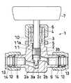
この実施形態の流体部品(1)は、ニードルストップバルブであり、管状の左方突出部(8)および管状の右方突出部(9)を下部に有する有底円筒状のボディ(2)と、ボディ(2)内に上下移動可能に挿入された円柱状ステム(3)と、ボディ(2)の上部内に嵌め入れられてステム(3)の上下移動を案内する円筒状ガイド(4)と、ボディ(2)の上部外周面に設けられたおねじ部(10)の下端部にねじ合わされたパネルナット(5)および同頂部にねじ合わされた袋ナット(6)と、ステム(3)の上端部に設けられたハンドル(7)とを備えている。
【0018】
ステム(3)、ガイド(4)、袋ナット(6)およびハンドル(7)がこの流体部品(1)のアクチュエータを構成している。
【0019】
ボディ(2)の下部には、中心部近くから若干左上がりにのびて左方突出部(8)内通路に通じる流体流入通路(2a)と、流体流入通路(2a)の中心側端部よりも上方の位置から若干右下がりにのびて右方突出部(9)内通路に通じる流体流出通路(2b)と、両通路(2a)(2b)を連通するように上下方向にのびる連通路(2c)とが設けられている。連通路(2c)は、下部が上部よりも小径の段付き状とされている。連通路(2c)よりも上方のボディ(2)の内周面は、上下方向にのびるステム案内路(11)とされている。ステム案内路(11)の下部には、連通路(2c)に若干かかるようにめねじ部(11a)が設けられており、同上部は、めねじ部(11a)より大径とされており、ここに円筒状ガイド(4)が嵌め入れられている。
【0020】
ステム(3)は、下端部(3a)が先細り円錐状とされており、円錐状部分(3a)の上方の部分に、他の部分よりも大径でボディ(2)のめねじ部(11a)にねじ合わされているおねじ部(3b)が設けられている。
【0021】
ガイド(4)は、その上端部をボディの上端面よりも突出させるように、めねじ部(11a)上端の段部によって受け止められている。袋ナット(6)の頂壁には、ステム(3)の上端部を挿通させる貫通孔が設けられており、この袋ナット(6)がボディ(2)のおねじ部(10)にねじ合わされることにより、ガイド(4)がボディ(2)に固定されている。ステム(3)の上端部は、袋ナット(6)よりも上方に突出させられており、ここにハンドル(7)が取り付けられている。
【0022】
ボディ(2)下部の管状左方突出部(8)および右方突出部(9)には、それぞれ管継手部が形成されており、各突出部(8)(9)から突出した管の周囲に嵌められるフロントリング(12)およびバックリング(13)と、フロントリング(12)およびバックリング(13)を締付けて管を各突出部(8)(9)に固定する袋ナット(14)とが各突出部(8)(9)に配置されている。
【0023】
各部材(2)(3)(4)(5)(6)(7)の材質については、ガイド(4)は、PTFE+PFA製で、ハンドル(7)がADC12製であり、ボディ(2)、ステム(3)、パネルナット(5)および袋ナット(6)は、重量%で、C:0.001〜0.01%、Si:5%以下、Mn:2%以下、P:0.03%以下、S:100ppm以下、O:50ppm以下で、Cr:18〜25%、Ni:15〜25%、Mo:4.5〜7.0%、Cu:0.5〜3.0%、N:0.1〜0.3%を含みかつ、残部が実質的にFeとその他の不可避的不純物からなる合金とされるとともに、合金の各成分の複合添加を基本に耐すきま腐食性を確保するため重量%で表示したCRI=[Cr]+4×[Mo]+30×[N]から求まるCRI値が40≦CRI≦55の範囲に設定されている。
【0024】
すなわち、ボディ(2)とナット(5)(6)先端部との接触部分、袋ナット(6)頂壁貫通孔周面とステム(3)との接触部分などは、隙間腐食が発生しやすい箇所であり、隙間腐食の起こりやすい使用状態にある金属製部材(2)(3)(5)(6)が、上記の合金製とされている。さらに、各金属製部材(2)(3)(6)の接触部分の表面は、Ra=0.1程度の表面粗さに仕上げられており、上記組成のステンレス鋼の採用との相乗効果により、耐隙間腐食性が向上させられている。
【0025】
なお、ボディ(2)下部の管状左方突出部(8)および右方突出部(9)に形成される管継手部のバックリング(13)および袋ナット(14)についても、隙間腐食向上のために、上記の合金製とされていることが好ましい。
【0026】
図2および図3は、この発明の流体部品の第2実施形態を示している。図2は、通路閉鎖状態を、図3は通路開放状態をそれぞれ示している。
【0027】
この実施形態の流体部品(21)は、ダイアフラムバルブであり、流体流入通路(22a)および流体流出通路(22b)を有するボディ(22)と、ボディ(22)の流体通路(22a)(22b)を開閉するダイヤフラム(23)と、ダイヤフラム(23)を開位置と閉位置とに移動させるアクチュエータ(24)とを備えている。
【0028】
ボディ(22)は、中央部に上向きの円形凹所(22c)を有しており、流体流入通路(22a)および流体流出通路(22b)の各内側端部は、この凹所(22c)に開口している。
【0029】
ダイヤフラム(23)は、吊り金具(23c)の先端が埋設された方形ダイヤフラム(23a)と、この方形ダイヤフラム(23a)の上面に密着して設けられた円形ダイヤフラム(23b)とからなる。ダイヤフラム(23)は、中央部が下方に突出するように成形されており、図2に示す通路閉鎖状態において、その中央部がボディ(22)の凹所(22c)底面に当接することにより、流体流入通路(22a)から流体流出通路(22b)に至る通路を閉鎖するようになされている。これにより、ボディ(22)の凹所(22c)側には、ダイヤフラム(23)を受ける突起(ウエア部)は存在せず、ボディ(22)内通路がストレートとなされている。
【0030】
アクチュエータ(24)は、頂壁を有する円筒状に形成されたボンネット(25)と、ボンネット(25)の頂壁に被せられたケーシング(26)と、下端部がダイヤフラム(23)の吊り金具(23c)に結合され、上端部がケーシング(26)よりも上方に突出させられているステム(27)と、ケーシング(26)内に上下移動可能に配置されてステム(27)の中間部分に固定されているピストン(28)と、ステム(27)下端部に設けられたダイヤフラム押さえ(29)とを有している。そして、ダイヤフラム(23)の方形ダイヤフラム(23a)の外周縁部がボンネット(25)のフランジ部(25a)とボディ(22)の開口縁部(22d)とによって挟持されるように、ボディ(22)、ダイヤフラム(23)およびアクチュエータ(24)が重ね合わされて、図示省略したねじ部材によって結合されることにより、ダイヤフラムバルブ(21)が組み立てられている。
【0031】
図2に示す通路閉鎖状態において、ピストン(28)よりも下方のケーシング(26)内に圧縮空気が導入されると、図3に示すように、ピストン(28)およびステム(27)が上方に移動し、ボディ(22)の凹所(22c)内に位置させられていたダイヤフラム(23)も上方に移動して通路開放状態となり、ボディ(22)内には、流体流入通路(22a)から流体流出通路(22b)に至るストレートな流路すなわち溜まりがない流路が形成される。通路開放状態では、ダイヤフラム(23)は、弾性変形により、ボンネット(25)のフランジ部(25a)とボディ(22)の開口縁部(22d)とによって挟持された外周縁部と中央部との間の環状部分が上に凸となるように変形する。
【0032】
各部材(22)(23)(25)(26)(27)(28)の材質については、ピストン(28)は、SUSF316L製であり、ダイヤフラム(23)は、方形ダイヤフラム(3a)がPTFE製で、円形ダイヤフラム(3b)がブチルゴム製であり、ボディ(22)、ボンネット(25)、ケーシング(26)およびステム(27)は、重量%で、C:0.001〜0.01%、Si:5%以下、Mn:2%以下、P:0.03%以下、S:100ppm以下、O:50ppm以下で、Cr:18〜25%、Ni:15〜25%、Mo:4.5〜7.0%、Cu:0.5〜3.0%、N:0.1〜0.3%を含みかつ、残部が実質的にFeとその他の不可避的不純物からなる合金とされるとともに、合金の各成分の複合添加を基本に耐すきま腐食性を確保するため重量%で表示したCRI=[Cr]+4×[Mo]+30×[N]から求まるCRI値が40≦CRI≦55の範囲に設定されている。
【0033】
すなわち、ボディ(22)とボンネット(25)とのダイヤフラム(23)を介しての突き合わせ部、ボンネット(25)とケーシング(26)との結合部、ケーシング(26)頂壁貫通孔周面とステム(27)との接触部分などは、隙間腐食が発生しやすい箇所であり、隙間腐食の起こりやすい使用状態にある金属製部材(22)(25)(26)(27)が、上記の合金製とされている。さらに、各金属製部材(22)(25)(26)(27)の接触部分の表面は、Ra=0.1程度の表面粗さに仕上げられており、上記組成のステンレス鋼の採用との相乗効果により、耐隙間腐食性が向上させられている。
【0034】
図4および図5は、この発明の流体部品の第3実施形態を示している。第3実施形態の説明において、図の左を前、右を後というものとする。
【0035】
この実施形態の流体部品(30)は、管継手であり、後端側から管(32)が挿入される管状ボディ(継手部材)(31)と、ボディ(31)の後端側から突出した管(32)の周囲に嵌められるフロントリング(33)およびバックリング(34)と、フロントリング(33)およびバックリング(34)を締付けて管(32)をボディ(31)に固定する袋ナット(35)とを備えている。
【0036】
ボディ(31)の中間部外周に外向きフランジ(36)が形成され、その前後両端部の外周におねじ部(37)(38)がそれぞれ形成されている。ボディ(31)の後端部の内周には、前側の部分より少し内径の大きい大径部(31a)が形成され、その後端部内周には、前細り状のテーパ面(31b)が形成されている。
【0037】
袋ナット(35)の前端部側の内周に、めねじ(35a)が形成されており、これがボディ(31)の後端部のおねじ部(38)にねじ嵌められている。袋ナット(35)の後端には、内向きフランジ(35b)が形成されている。
【0038】
フロントリング(33)の外周には、ボディ(31)後端のテーパ面(31b)に合致するテーパ面(33a)が形成され、同後端部内周には前細りテーパ状の環状凹部(33b)が形成されている。バックリング(34)の前端には、フロントリング(33)の凹部(33b)に嵌まり込む前細りテーパ状の環状凸部(34a)が形成されている。
【0039】
上記管継手(30)において、袋ナット(35)を締付けると、袋ナット(35)の内向きフランジ(35b)の前面がバックリング(34)の後面に当り、これを前進させる。すると、バックリング(34)の凸部(34a)がフロントリング(33)の凹部(33b)内に嵌まり込み、フロントリング(33)をバックリング(34)とともに前進させ、フロントリング(33)の前端部がボディ(31)のテーパ面(31b)に当る。さらに、締め付けると、フロントリング(33)およびバックリング(34)の各前端部が内方に変形させられて、管(32)に食い込み、管(32)が強く締付けられる。
【0040】
各部材(31)(33)(34)(35)の材質については、フロントリング(33)は、SUS316製であり、ボディ(31)、バックリング(34)および袋ナット(35)は、重量%で、C:0.001〜0.01%、Si:5%以下、Mn:2%以下、P:0.03%以下、S:100ppm以下、O:50ppm以下で、Cr:18〜25%、Ni:15〜25%、Mo:4.5〜7.0%、Cu:0.5〜3.0%、N:0.1〜0.3%を含みかつ、残部が実質的にFeとその他の不可避的不純物からなる合金とされるとともに、合金の各成分の複合添加を基本に耐すきま腐食性を確保するため重量%で表示したCRI=[Cr]+4×[Mo]+30×[N]から求まるCRI値が40≦CRI≦55の範囲に設定されている。
【0041】
すなわち、ボディ(31)と袋ナット(35)とのねじ合わせ部、袋ナット(35)とバックリング(34)との接触部分などは、隙間腐食が発生しやすい箇所であり、隙間腐食の起こりやすい使用状態にある金属製部材(31)(34)(35)が、上記の合金製とされている。
【0042】
図6は、この発明の流体部品の第4実施形態を示している。
【0043】
この実施形態の流体部品(40)は、管継手であり、互いに連通する流体通路(41b)(42b)を有している管状の第1および第2の継手部材(41)(42)と、両継手部材(41)(42)の突き合わせ端面間に介在させられるガスケット(43)と、両継手部材(41)(42)を結合するねじ手段とを備え、第1および第2継手部材(41)(42)の突き合わせ端面には、ガスケット押さえ用の環状突起(41a)(42a)が設けられており、第2継手部材(42)の端部近くには、フランジ部(42c)が設けられている。ねじ手段は、第1継手部材(41)に設けられたおねじ部(46)と、頂壁内面がフランジ部(42c)にスラストリング(45)を介して当接するように第2継手部材(42)に嵌められかつ第1継手部材(41)のおねじ部(46)にねじ合わされている袋ナット(44)とよりなる。
【0044】
この管継手(40)では、第1の継手部材(41)にねじ合わされた袋ナット(44)を締め付けることにより、ガスケット(43)が変形して適正なシール力が得られる。
【0045】
各部材(41)(42)(43)(44)の材質については、ガスケット(43)は、SUS316製であり、第1継手部材(41)、第2継手部材(43)および袋ナット(44)は、重量%で、C:0.001〜0.01%、Si:5%以下、Mn:2%以下、P:0.03%以下、S:100ppm以下、O:50ppm以下で、Cr:18〜25%、Ni:15〜25%、Mo:4.5〜7.0%、Cu:0.5〜3.0%、N:0.1〜0.3%を含みかつ、残部が実質的にFeとその他の不可避的不純物からなる合金とされるとともに、合金の各成分の複合添加を基本に耐すきま腐食性を確保するため重量%で表示したCRI=[Cr]+4×[Mo]+30×[N]から求まるCRI値が40≦CRI≦55の範囲に設定されている。
【0046】
すなわち、第1継手部材(31)と袋ナット(44)とのねじ合わせ部、袋ナット(44)頂壁貫通孔周面と第2継手部材(43)との接触部分などは、隙間腐食が発生しやすい箇所であり、隙間腐食の起こりやすい使用状態にある金属製部材(41)(43)(44)が、上記の合金製とされている。
【0047】
本発明は、特に薬品及び食品を製造・貯蔵・輸送する際に用いられる流体部品で生じるすきま腐食損傷に対して流体部品の化学成分と耐すきま腐食性指標CRI値を厳密に限定することで優れた耐久性を得るものである。この目的のために本発明者らは流体部品の材質であるステンレス鋼中の主要合金成分であるCr量,Ni量,Mo量,Cu量,N量,W量,V量を限られた範囲で耐すきま腐食性指標CRI値の下限値以上に限定すると、上記環境において優れた耐久性が得られることを見いだしたのである。
【0048】
以下に、本発明にかかる流体部品を構成する合金(ステンレス鋼)の構成要件の限定理由を述べる。
【0049】
[C量:0.001〜0.01%]
Cは一般的にステンレス鋼の耐食性に有害であるが、強度の観点からある程度の含有量は必要である。0.001%未満の極低C量では製造コストが高くなる。また、0.01%を越えると耐食性を大幅に劣化させるため0.001%以上0.01%以下とした。
【0050】
[Si量:5%以下]
Siはステンレス鋼の耐酸化性の向上に有効な元素である。5%を越えると熱間加工性が著しく劣化する。よって、Si量を5.0%以下に限定した。
【0051】
[Mn量:2%以下]
Mnはオ−ステナイト安定化元素であり、高価なNiの代替として添加することが可能であるが、本発明の対象としている塩水中での耐食性は、2.0%超では効果がなく、耐食性に影響を及ぼさないMn量の上限として2.0%以下とした。
【0052】
[P量:0.03%以下]
Pは耐食性および熱間加工性の観点から少ないことが望ましい。0.03%を超えると熱間加工性が極端に劣化する。よって、P量は0.03%以下とした。
【0053】
[S量:100ppm以下]
Sは耐食性もさることながら熱間加工性にも著しく影響する元素で、その量は低いほど良い。そこでS量は100ppm(0.01%)以下とした。
【0054】
[O量50ppm以下]
OもSと同様に熱間加工性に著しく影響する元素であり、低いほど良い。Oは通常のステンレス鋼製鋼法で得られる50ppm以下と限定した。
【0055】
[Cr量:18%以上25%以下]
Crは本発明の基本成分である。Ni,Mo,Cu,Nと共存した形で添加される。良好な耐食性を得るには18%以上の添加が必要である。Cr量が多いほど耐食性は向上するが、25%を超える場合には製造性がやや困難になり、経済的にも高価となる。よって、Cr量の範囲を18%以上25%以下に限定した。
【0056】
[Ni量:15%以上25%以下]
NiはCr,Mo,Cu,Nとともに本発明のステンレス鋼の基本成分である。また、ステンレス鋼の厚板製造を容易にするために金属組織をオ−ステナイト相にする必要があり、Ni添加は必須である。本発明鋼をオ−ステナイト相にするための最低限のNi量は15%である。また、Ni量が多すぎると価格が高くなるだけでなく製造性も困難になる。経済的にも安価でオ−ステナイト相を保つNi量の上限として25%とした。
【0057】
[Mo量:4.5%以上7.0%以下]
MoはCr,Ni,Cu,Nとともに本発明のステンレス鋼の基本成分である。塩水環境中で高い耐食性を得るために必須な元素である。4.5%〜7.0%の範囲でCr,Nと共存して効果的になる。4.5%未満では耐食性が不十分となるが、7.0%を越えても耐食性の改善効果が飽和し、製造製が困難となりかつ高価となる。
【0058】
[Cu量:0.5%以上3.0%以下]
CuはCr,Ni,Mo,Nと共存の形で塩水環境で高い耐食性を得るために必須な元素である。0.5%以上の添加で共存添加効果が著しく、他方、3.0%を越えると耐食性は飽和し、かつ、熱間加工性を劣化させる。よって、Cu量を0.5%〜3.0%に限定した。
【0059】
[N量0.1%以上0.3%以下]
NはCr,Ni,Mo,Cuと共存した形で基本成分として添加される。Nは強いオ−ステナイト形成元素であると同時にステンレス鋼に発生するすきま腐食の進行を阻害する元素でもある。安定した耐食性を得るためには少なくとも0.1%以上のN量が必要である。また、0.3%以上の添加は製鋼上、非常に困難であり、かつステンレス鋼の熱間加工性を劣化させる。よって、N量の範囲を0.1%以上0.3%以下と限定した。
【0060】
[W量:2%以下]
WはCr,Mo,N,Vと共存した形で添加すると不動態皮膜がさらに安定化し、海水中でのステンレス鋼の耐すきま腐食性を向上させる。環境に応じて2%以下で添加する。というのは2%を越えて添加すると熱間加工性を著しく阻害するからである。
【0061】
[V量:2%以下]
VをCr,Mo,N,Wと共存した形で添加すると不動態皮膜がさらに安定化され、海水中での耐すきま腐食性が向上する。環境に応じて2%以下で添加する。V量が多いほど耐すきま腐食性は向上するが、2%を超えて添加するとステンレス鋼の熱間加工性が著しく劣化し、鋼製造が困難となり、経済的にも高価となる。よって、V量の上限を2%に限定した。
【0062】
[CRI値40以上55以下]
[Cr]+4×[Mo]+30×[N]で計算されるCRI値が40以上であれば実質的にステンレス鋼にはすきま腐食は発生しない。また、55を超えると鋼製造コストが多大となり、汎用性に問題が生じたり、バルブ製造コストも増大する。よって、優れた耐すきま腐食性の確保と低コスト化の観点からCRI値の限定範囲を40以上55以下とした。
【0063】
上記第1から第4までの実施形態において、上記の合金製とされた各金属製部材(2)(3)(6)(22)(25(26)(27)(31)(34)(35)(41)(43)(44)の接触部分の表面は、Ra=0.1程度の表面粗さに仕上げられている。これにより、耐隙間腐食性がより起こりにくいようになされている。
【0064】
【実施例】
以下に実施例に基づいて本発明を説明する。
【0065】
表1は本発明流体部品ならびに比較品の化学組成および常温の自然海水を約半年間流し続けたあとのすきま腐食損傷の有無及び総合的な評価をおこなった結果を比較したものである。
【0066】
流体部品用の素材はそれぞれ電気炉−AOD法及び電気炉−VAC法によって溶製した。これらの溶鋼を連続スラブに通常条件で鋳造した。さらに、1150℃から1250℃で0.5から1時間のソーキング処理を施した。表面手入れ後、図2および図3に示したバルブを製作し、溶体化処理をおこない、それぞれの試験に供した。表面粗さについては、いずれもRa=0.1とした。
【0067】
総合的な評価は自然海水中の暴露試験結果とCRI値から以下のようにおこなった。
【0068】
◎印:すきま腐食損傷がなく、CRI値が40以上55以下を満足するバルブ。
【0069】
×印:上記条件のいずれか一方または、両方を満足しないバルブ。
【0070】
表1において、CRI値が35未満のものは、全て隙間腐食が発生しており、また、CRI値が42.93であるバルブ番号5のものでは、Ni,MoおよびCuの量が少なく、Crの量だけを多くしてCRI値を大きくしても、それだけでは隙間腐食を防ぐことはできないことを意味している。そして、Cr:18〜25%、Ni:15〜25%、Mo:4.5〜7.0%、Cu:0.5〜3.0%、N:0.1〜0.3%の範囲を守って、CRI値を40以上としたものは、いずれも隙間腐食は発生していない。
【0071】
表1の結果から本発明による流体部品が極めて優れた耐すきま腐食性を有していることがわかる。
【0072】
【表1】
【0074】
【発明の効果】
以上に述べたように、本発明のバルブの使用により薬品および食品によるすきま腐食損傷が激減し、腐食損傷部の補修・交換することなくバルブの長期にわたる耐久性を確保することが可能となった。したがって、本発明の価値は極めて高い。
【図面の簡単な説明】
【図1】この発明による流体部品の第1実施形態としてのバルブを示す断面図である。
【図2】この発明による流体部品の第2実施形態としてのダイヤフラムバルブの流路閉鎖状態を示す断面図である。
【図3】図2のバルブの流路開放状態を示す縦断面図である。
【図4】この発明による流体部品の第3実施形態としての管継手を示す分解縦断面図である。
【図5】図4の管継手の組立状態を示す縦断面図である。
【図6】この発明による流体部品の第4実施形態としての管継手を示す分解縦断面図である。
【符号の説明】
(1) バルブ(流体部品)
(2) ボディ
(3) ステム
(6) 袋ナット
(21) ダイヤフラムバルブ(流体部品)
(22) ボディ
(23) ダイヤフラム
(25) ボンネット
(26) ケーシング
(27) ステム
(30) 管継手(流体部品)
(31) ボディ(継手部材)
(34) バックリング
(35) 袋ナット
(40) 管継手(流体部品)
(41) 第1継手部材
(42) 第2継手部材
(44) 袋ナット[0001]
BACKGROUND OF THE INVENTION
The present invention relates to a fluid component such as a joint used in a piping system or a fluid control device such as a valve used in a fluid control device, and more particularly, a fluid component suitable for use in a pharmaceutical or food manufacturing apparatus. About.
[0002]
[Prior art]
Joints, valves, etc. (collectively referred to as fluid parts) are often used as general-purpose parts in fluid control devices and various pipes.
[0003]
For example, reaction vessels used in the manufacture of chemicals and foods and tanks used for storing and transporting chemicals and foods themselves use metal valves for the purpose of loading and unloading raw materials and products. Yes. Depending on the chemicals and food components, purity, and temperature, metal valves can be selected from carbon steel, low alloy steel, stainless steel, Ni-base alloy, titanium, Ni / Cu alloy, etc. Stainless steels such as SUS304 steel and SUS316L steel, which are generally considered to have good corrosion resistance, are often used in metal valves used when manufacturing, storing and transporting such raw materials and products. However, most of the corrosion damage to metal valves is crevice corrosion due to chloride ions contained in chemicals and foods. Also, in many cases, it is common to perform maintenance such as washing / sterilization inside the valve to prevent crevice corrosion and germs increase in the valve, but if the washing / sterilization and drying process is incomplete, Since chloride ions often remain on the valve inner surface and clearance structure, crevice corrosion tends to occur frequently in the tightening and packing parts of the valve body and flange, and it takes a lot of time and labor to repair it. At the same time, metal ions and the like generated by crevice corrosion are very important problems because they degrade the product quality.
[0004]
[Problems to be solved by the invention]
Therefore, if an attempt is made to improve the corrosion resistance of a member made of SUS316 so that the problem of corrosion does not occur even when used in a food or pharmaceutical manufacturing apparatus that handles a high salt solution, there is another problem such as a decrease in strength and hardness. As new problems arise, it has become nearly impossible to improve only the crevice corrosion resistance of conventional fluid parts that meet the required specifications while maintaining other characteristics.
[0005]
An object of the present invention is to provide a fluid component that can improve crevice corrosion resistance while maintaining other performances.
[0006]
[Means for Solving the Problems]
The present invention provides a fluid component for solving the above-mentioned problems. From the above viewpoint, investigations were made on chemicals and food environments in which crevice corrosion occurs when fluid components such as valves and joints are exposed. . As a result, it has been found that crevice corrosion damage often occurs in chemicals and foods and contains chloride ions. As a corrosive environment for evaluating the crevice corrosion, it has been found that it can be simulated in a seawater environment. Against this background, exposure tests of various stainless steel valves were conducted in natural seawater. Specifically, we continued flowing normal temperature natural seawater through the valve for about half a year to observe the corrosion status and investigated the presence or absence of crevice corrosion damage. As a result of diligent efforts in this way, fluid flow control valves for manufacturing, storage and transportation and fluid flow control valves that do not cause crevice corrosion, which has been a problem in the past, pipe fittings for piping for manufacturing, storage and transportation The present invention has been completed as a result of specifying the above, and the gist thereof is as follows.
[0007]
The fluid component according to the present invention is a fluid component such as a valve or a joint used in a pipe and a fluid control device, and is constituted by a plurality of constituent members. A predetermined metal member having a contact surface that contacts any one of the contact surfaces and an end of the contact surface exposed to the outer surface of the fluid component is C: 0.001 to 0.01% by weight%. Si: 5% or less, Mn: 2% or less, P: 0.03% or less, S: 100ppm or less, O: 50ppm or less, Cr: 18-25%, Ni: 15-25%, Mo: 4. The alloy contains 5 to 7.0%, Cu: 0.5 to 3.0%, N: 0.1 to 0.3%, and the balance is substantially composed of Fe and other inevitable impurities. In addition, the crevice corrosion resistance is confirmed based on the combined addition of each component of the alloy. Following formula CRI was in% by weight to: in which (Crevice Corrosion Resistance Index crevice corrosion resistance index) value characterized in that it is a 40 ≦ CRI ≦ 55.
[0008]
CRI = [Cr] + 4 × [Mo] + 30 × [N].
[0009]
Furthermore, it is preferable to contain one or more of W: 2% or less and V: 2% or less, respectively.
[0010]
According to the fluid component of the present invention, the fluid component has a contact surface that contacts any one of the other component members of the fluid component, and an end of the contact surface is exposed to the outer surface of the fluid component. The material of the predetermined metal member, that is, the member susceptible to crevice corrosion, is C: 0.001 to 0.01%, Si: 5% or less, Mn: 2% or less, P: 0.03. %: S: 100 ppm or less, O: 50 ppm or less, Cr: 18-25%, Ni: 15-25%, Mo: 4.5-7.0%, Cu: 0.5-3.0%, N: Contains 0.1 to 0.3%, and the balance is substantially composed of Fe and other inevitable impurities, and ensures crevice corrosion resistance based on the combined addition of each component of the alloy. CRI expressed in weight% = [Cr] + 4 × [Mo] + 30 × [N] The CRI value obtained from the above is set in the range of 40 ≦ CRI ≦ 55, so that the crevice corrosion resistance can be improved without the strength reduction and the hardness reduction that have been regarded as the disadvantages associated with the crevice corrosion resistance improvement. Can do.
[0011]
The surface roughness of the metal member is preferably Ra1 or less, more preferably Ra0.2 or less.
[0012]
Examples of the fluid component include a joint and a valve, but are not limited thereto, and various types of fluid components are possible.
[0013]
For example, the fluid component may be a valve including a body, an actuator, and a screw member, and at least one of the body, the actuator, and the screw member may be a predetermined metal (that is, the above-described alloy) member, Further, the fluid component is a diaphragm valve in which a non-metallic diaphragm is sandwiched between a metallic body and a metallic bonnet, and both the body and the bonnet are made of a predetermined metallic member (that is, made of the above alloy). Sometimes. In the latter case, the diaphragm holding part of the body and bonnet is in a state where crevice corrosion is extremely likely to occur, and by improving the crevice corrosion resistance of this part, the durability of the diaphragm valve as a whole can be dramatically improved. Can do.
[0014]
Furthermore, the fluid component is a pipe joint that is assembled by tightening a cap nut on a male thread portion provided on the outer periphery of a tubular joint member, and at least one of the joint member and the cap nut is made of a predetermined metal ( That is, it may be a member made of the above alloy).
[0015]
DETAILED DESCRIPTION OF THE INVENTION
Embodiments of the present invention will be described below with reference to the drawings. The present invention is not limited to the drawings shown here.
[0016]
FIG. 1 shows a first embodiment of a fluid component according to the present invention. In the description of the first embodiment, the left and right sides of the figure are referred to as left and right.
[0017]
The fluid component (1) of this embodiment is a needle stop valve, and has a bottomed cylindrical body (2) having a tubular left protrusion (8) and a tubular right protrusion (9) at the bottom. A cylindrical stem (3) inserted into the body (2) so as to be movable up and down, and a cylindrical guide (4) fitted into the upper part of the body (2) to guide the vertical movement of the stem (3) A panel nut (5) screwed to the lower end of the external thread (10) provided on the upper outer peripheral surface of the body (2), a cap nut (6) screwed to the top, and a stem (3) And a handle (7) provided at the upper end of the.
[0018]
The stem (3), guide (4), cap nut (6) and handle (7) constitute the actuator of the fluid component (1).
[0019]
At the lower part of the body (2), a fluid inflow passage (2a) extending from the vicinity of the center slightly upward to the left protruding portion (8) and leading to the inner passage, and from the center side end of the fluid inflow passage (2a) The fluid outflow passage (2b) extending slightly downward from the upper position to the rightward projecting portion (9) and the communication passage extending in the vertical direction so as to communicate both passages (2a) and (2b) ( 2c). The communication path (2c) has a stepped shape in which the lower part has a smaller diameter than the upper part. The inner peripheral surface of the body (2) above the communication path (2c) is a stem guide path (11) extending in the vertical direction. The lower part of the stem guide path (11) is provided with a female screw part (11a) so as to be slightly applied to the communication path (2c), and the upper part has a larger diameter than the female screw part (11a). Here, a cylindrical guide (4) is fitted.
[0020]
The stem (3) is tapered at the lower end (3a), and the upper part of the conical part (3a) has a larger diameter than the other part and the female thread part (11a) of the body (2). ) Is provided with a male screw part (3b) screwed together.
[0021]
The guide (4) is received by a step at the upper end of the female screw portion (11a) so that the upper end of the guide (4) protrudes from the upper end surface of the body. The top wall of the cap nut (6) is provided with a through hole through which the upper end of the stem (3) is inserted, and this cap nut (6) is screwed onto the threaded portion (10) of the body (2). Thus, the guide (4) is fixed to the body (2). The upper end portion of the stem (3) is projected upward from the cap nut (6), and a handle (7) is attached thereto.
[0022]
A pipe joint portion is formed on each of the tubular left projecting portion (8) and the right projecting portion (9) at the lower part of the body (2), and the periphery of the tube projecting from each projecting portion (8) (9). A front ring (12) and a back ring (13) to be fitted to each other, and a cap nut (14) for fastening the front ring (12) and the back ring (13) to fix the pipe to each protrusion (8) (9) Is arranged in each protrusion (8) (9).
[0023]
Regarding the material of each member (2) (3) (4) (5) (6) (7), the guide (4) is made of PTFE + PFA, the handle (7) is made of ADC12, the body (2), The stem (3), the panel nut (5) and the cap nut (6) are in weight%, C: 0.001 to 0.01%, Si: 5% or less, Mn: 2% or less, P: 0.03 %: S: 100 ppm or less, O: 50 ppm or less, Cr: 18-25%, Ni: 15-25%, Mo: 4.5-7.0%, Cu: 0.5-3.0%, N: Contains 0.1 to 0.3%, and the balance is substantially composed of Fe and other inevitable impurities, and ensures crevice corrosion resistance based on the combined addition of each component of the alloy. Therefore, the CRI value obtained from CRI = [Cr] + 4 × [Mo] + 30 × [N] expressed in weight% is The range is set to 40 ≦ CRI ≦ 55.
[0024]
That is, crevice corrosion is likely to occur at the contact portion between the body (2) and the nut (5) (6) tip, the contact portion between the cap nut (6) top wall through hole peripheral surface and the stem (3). The metal members (2), (3), (5), and (6) that are places and are in a use state in which crevice corrosion is likely to occur are made of the above-described alloy. Furthermore, the surface of the contact portion of each metal member (2) (3) (6) is finished to a surface roughness of about Ra = 0.1, and due to a synergistic effect with the adoption of stainless steel having the above composition. The crevice corrosion resistance is improved.
[0025]
In addition, the crevice corrosion is also improved for the buckling (13) and the cap nut (14) of the pipe joint portion formed in the tubular left protrusion (8) and the right protrusion (9) at the lower part of the body (2). Therefore, it is preferable to be made of the above alloy.
[0026]
2 and 3 show a second embodiment of the fluid component of the present invention. FIG. 2 shows the passage closed state, and FIG. 3 shows the passage open state.
[0027]
The fluid component (21) of this embodiment is a diaphragm valve, and includes a body (22) having a fluid inflow passage (22a) and a fluid outflow passage (22b), and fluid passages (22a) (22b) of the body (22). And a actuator (24) for moving the diaphragm (23) between an open position and a closed position.
[0028]
The body (22) has an upward circular recess (22c) at the center, and each inner end of the fluid inflow passage (22a) and the fluid outflow passage (22b) is formed in the recess (22c). It is open.
[0029]
The diaphragm (23) includes a rectangular diaphragm (23a) in which a tip of a hanging metal fitting (23c) is embedded, and a circular diaphragm (23b) provided in close contact with the upper surface of the rectangular diaphragm (23a). The diaphragm (23) is shaped so that the central portion protrudes downward. When the passage is closed as shown in FIG. 2, the central portion abuts the bottom surface of the recess (22c) of the body (22). The passage from the fluid inflow passage (22a) to the fluid outflow passage (22b) is closed. Thereby, the protrusion (wear part) which receives the diaphragm (23) does not exist in the recess (22c) side of the body (22), and the passage in the body (22) is straight.
[0030]
The actuator (24) includes a bonnet (25) formed in a cylindrical shape having a top wall, a casing (26) covered on the top wall of the bonnet (25), and a hanging bracket (26) whose lower end is a diaphragm (23). 23c), a stem (27) whose upper end protrudes upward from the casing (26), and is arranged in the casing (26) so as to be vertically movable and fixed to an intermediate portion of the stem (27). And a diaphragm presser (29) provided at the lower end of the stem (27). The outer peripheral edge of the rectangular diaphragm (23a) of the diaphragm (23) is sandwiched between the flange (25a) of the bonnet (25) and the opening edge (22d) of the body (22). ), The diaphragm (23) and the actuator (24) are overlapped and joined by a screw member (not shown) to assemble the diaphragm valve (21).
[0031]
When the compressed air is introduced into the casing (26) below the piston (28) in the passage closed state shown in FIG. 2, the piston (28) and the stem (27) are moved upward as shown in FIG. The diaphragm (23), which has been moved and located in the recess (22c) of the body (22), also moves upward to open the passage, and into the body (22) from the fluid inflow passage (22a). A straight flow path leading to the fluid outflow passage (22b), that is, a flow path having no accumulation is formed. In the state where the passage is open, the diaphragm (23) is elastically deformed, and the outer peripheral edge portion and the central portion sandwiched between the flange portion (25a) of the bonnet (25) and the opening edge portion (22d) of the body (22). It deform | transforms so that the annular part in between may become convex upwards.
[0032]
Regarding the material of each member (22) (23) (25) (26) (27) (28), the piston (28) is made of SUSF316L, and the diaphragm (23) is made of PTFE made of PTFE. The circular diaphragm (3b) is made of butyl rubber, and the body (22), the bonnet (25), the casing (26), and the stem (27) are C: 0.001 to 0.01% by weight, Si: : 5% or less, Mn: 2% or less, P: 0.03% or less, S: 100ppm or less, O: 50ppm or less, Cr: 18-25%, Ni: 15-25%, Mo: 4.5- 7.0%, Cu: 0.5-3.0%, N: 0.1-0.3% and the balance is made of an alloy substantially consisting of Fe and other inevitable impurities, Resistant to the combined addition of each component of the alloy Or CRI values obtained from CRI were in% by weight for ensuring the corrosion resistance = [Cr] + 4 × [Mo] + 30 × [N] is set to a range of 40 ≦ CRI ≦ 55.
[0033]
That is, the butted portion of the body (22) and the bonnet (25) through the diaphragm (23), the connecting portion of the bonnet (25) and the casing (26), the casing (26) top wall through hole peripheral surface and the stem The contact portion with (27) is a portion where crevice corrosion is likely to occur, and the metal members (22), (25), (26), and (27) in a use state where crevice corrosion is likely to occur are made of the above-mentioned alloy. It is said that. Further, the surface of the contact portion of each metal member (22) (25) (26) (27) is finished to a surface roughness of about Ra = 0.1, and the use of stainless steel having the above composition is used. Due to the synergistic effect, the crevice corrosion resistance is improved.
[0034]
4 and 5 show a third embodiment of the fluid component of the present invention. In the description of the third embodiment, the left side of the figure is the front and the right side is the back.
[0035]
The fluid component (30) of this embodiment is a pipe joint, which protrudes from the rear end side of the tubular body (joint member) (31) into which the pipe (32) is inserted from the rear end side. Front ring (33) and back ring (34) fitted around pipe (32), and cap nut for fastening pipe (32) to body (31) by tightening front ring (33) and back ring (34) (35).
[0036]
An outward flange (36) is formed on the outer periphery of the intermediate portion of the body (31), and screw portions (37) and (38) are formed on the outer periphery of both front and rear ends thereof. A large diameter portion (31a) having a slightly larger inner diameter than the front portion is formed on the inner periphery of the rear end portion of the body (31), and a front tapered surface (31b) is formed on the inner periphery of the rear end portion. Has been.
[0037]
A female thread (35a) is formed on the inner periphery of the cap nut (35) on the front end side, and this is screwed onto the male thread (38) at the rear end of the body (31). An inward flange (35b) is formed at the rear end of the cap nut (35).
[0038]
A tapered surface (33a) that matches the tapered surface (31b) of the rear end of the body (31) is formed on the outer periphery of the front ring (33), and an annular recess (33b) that is tapered forward is formed on the inner periphery of the rear end. ) Is formed. The front end of the back ring (34) is formed with a front taper-shaped annular convex portion (34a) that fits into the concave portion (33b) of the front ring (33).
[0039]
When the cap nut (35) is tightened in the pipe joint (30), the front surface of the inward flange (35b) of the cap nut (35) hits the rear surface of the buckling (34) and advances it. Then, the convex part (34a) of the back ring (34) fits into the concave part (33b) of the front ring (33), and the front ring (33) is moved forward together with the back ring (34), so that the front ring (33) The front end portion of the body contacts the tapered surface (31b) of the body (31). Further, when tightened, the front end portions of the front ring (33) and the back ring (34) are deformed inward, bite into the tube (32), and the tube (32) is strongly tightened.
[0040]
Regarding the material of each member (31) (33) (34) (35), the front ring (33) is made of SUS316, and the body (31), the back ring (34) and the cap nut (35) are weights. %: C: 0.001 to 0.01%, Si: 5% or less, Mn: 2% or less, P: 0.03% or less, S: 100 ppm or less, O: 50 ppm or less, Cr: 18-25 %, Ni: 15-25%, Mo: 4.5-7.0%, Cu: 0.5-3.0%, N: 0.1-0.3%, and the balance is substantially CRI = [Cr] + 4 × [Mo] + 30 × expressed in weight% in order to ensure crevice corrosion resistance based on the combined addition of each component of the alloy, together with an alloy composed of Fe and other inevitable impurities. The CRI value obtained from [N] is set in the range of 40 ≦ CRI ≦ 55. The
[0041]
That is, the screw joint between the body (31) and the cap nut (35), the contact portion between the cap nut (35) and the buckling (34), and the like are portions where crevice corrosion is likely to occur, and crevice corrosion occurs. The metal members (31), (34), and (35) in an easy-to-use state are made of the above alloy.
[0042]
FIG. 6 shows a fourth embodiment of the fluid component of the present invention.
[0043]
The fluid component (40) of this embodiment is a pipe joint, tubular first and second joint members (41) (42) having fluid passages (41b) (42b) communicating with each other, and A gasket (43) interposed between the butted end faces of both joint members (41) and (42), and screw means for joining both joint members (41) and (42), and the first and second joint members (41 ) (42) is provided with annular protrusions (41a) (42a) for holding the gasket, and a flange portion (42c) is provided near the end of the second joint member (42). ing. The screw means includes a second joint member (46) provided so that the male thread portion (46) provided in the first joint member (41) and the inner surface of the top wall abut on the flange portion (42c) via the thrust ring (45). 42) and a cap nut (44) screwed onto the male thread portion (46) of the first joint member (41).
[0044]
In this pipe joint (40), by tightening the cap nut (44) screwed onto the first joint member (41), the gasket (43) is deformed to obtain an appropriate sealing force.
[0045]
Regarding the material of each member (41) (42) (43) (44), the gasket (43) is made of SUS316, and the first joint member (41), the second joint member (43), and the cap nut (44 ) Is by weight, C: 0.001 to 0.01%, Si: 5% or less, Mn: 2% or less, P: 0.03% or less, S: 100ppm or less, O: 50ppm or less, Cr : 18-25%, Ni: 15-25%, Mo: 4.5-7.0%, Cu: 0.5-3.0%, N: 0.1-0.3% and the balance Is substantially composed of Fe and other inevitable impurities, and CRI = [Cr] + 4 × [expressed in weight% to ensure crevice corrosion resistance based on the combined addition of the components of the alloy. The CRI value obtained from Mo] + 30 × [N] is set in the range of 40 ≦ CRI ≦ 55. Yes.
[0046]
That is, crevice corrosion occurs at the screw joint portion between the first joint member (31) and the cap nut (44), the contact portion between the cap nut (44) top wall through-hole peripheral surface and the second joint member (43). The metal members (41), (43), and (44) that are likely to occur and are in a use state in which crevice corrosion is likely to occur are made of the above-described alloy.
[0047]
The present invention is excellent by strictly limiting the chemical composition of the fluid component and the crevice corrosion resistance index CRI value particularly for crevice corrosion damage caused by fluid components used in manufacturing, storing and transporting chemicals and foods. Durability. For this purpose, the inventors limited the Cr content, Ni content, Mo content, Cu content, N content, W content, and V content, which are the main alloy components in stainless steel, which is the material of the fluid component. Thus, it has been found that when the crevice corrosion resistance index CRI value is limited to the lower limit value or more, excellent durability can be obtained in the above environment.
[0048]
The reasons for limiting the constituent requirements of the alloy (stainless steel) constituting the fluid component according to the present invention will be described below.
[0049]
[C amount: 0.001 to 0.01%]
C is generally harmful to the corrosion resistance of stainless steel, but a certain content is necessary from the viewpoint of strength. With an extremely low C content of less than 0.001%, the manufacturing cost increases. On the other hand, if it exceeds 0.01%, the corrosion resistance is greatly deteriorated.
[0050]
[Si content: 5% or less]
Si is an element effective for improving the oxidation resistance of stainless steel. If it exceeds 5%, the hot workability is remarkably deteriorated. Therefore, the Si content is limited to 5.0% or less.
[0051]
[Mn content: 2% or less]
Mn is an austenite stabilizing element and can be added as an alternative to expensive Ni. However, the corrosion resistance in salt water, which is the object of the present invention, is not effective when the content exceeds 2.0%, and corrosion resistance. The upper limit of the amount of Mn that does not affect the content is 2.0% or less.
[0052]
[P amount: 0.03% or less]
P is desirably small in terms of corrosion resistance and hot workability. When it exceeds 0.03%, hot workability is extremely deteriorated. Therefore, the P content is set to 0.03% or less.
[0053]
[S amount: 100 ppm or less]
S is an element that significantly affects hot workability as well as corrosion resistance. The lower the amount, the better. Therefore, the amount of S is set to 100 ppm (0.01%) or less.
[0054]
[O content 50 ppm or less]
O, like S, is an element that significantly affects hot workability, and the lower the better. O was limited to 50 ppm or less obtained by an ordinary stainless steel manufacturing method.
[0055]
[Cr content: 18% to 25%]
Cr is a basic component of the present invention. It is added in the form of coexistence with Ni, Mo, Cu, and N. In order to obtain good corrosion resistance, addition of 18% or more is necessary. The corrosion resistance improves as the Cr content increases, but if it exceeds 25%, the productivity becomes somewhat difficult, and the cost becomes expensive. Therefore, the range of the Cr amount is limited to 18% or more and 25% or less.
[0056]
[Ni content: 15% to 25%]
Ni, together with Cr, Mo, Cu, and N, is a basic component of the stainless steel of the present invention. Further, in order to facilitate the production of a stainless steel plate, the metal structure needs to be an austenite phase, and Ni addition is essential. The minimum amount of Ni for making the steel of the present invention an austenite phase is 15%. Further, when the amount of Ni is too large, not only the price increases but also the manufacturability becomes difficult. The upper limit of the amount of Ni that keeps the austenite phase economically is set to 25%.
[0057]
[Mo content: 4.5% to 7.0%]
Mo is a basic component of the stainless steel of the present invention together with Cr, Ni, Cu and N. It is an essential element for obtaining high corrosion resistance in a saltwater environment. Effective in the range of 4.5% to 7.0% coexisting with Cr and N. If it is less than 4.5%, the corrosion resistance becomes insufficient, but if it exceeds 7.0%, the effect of improving the corrosion resistance is saturated, making the production difficult and expensive.
[0058]
[Cu content: 0.5% to 3.0%]
Cu is an essential element for obtaining high corrosion resistance in a salt water environment in the form of coexistence with Cr, Ni, Mo, and N. If the addition is 0.5% or more, the coexistence addition effect is remarkable, and if it exceeds 3.0%, the corrosion resistance is saturated and the hot workability is deteriorated. Therefore, the amount of Cu is limited to 0.5% to 3.0%.
[0059]
[N content 0.1% or more and 0.3% or less]
N is added as a basic component in the form of coexistence with Cr, Ni, Mo and Cu. N is a strong austenite forming element and also an element that inhibits the progress of crevice corrosion occurring in stainless steel. In order to obtain stable corrosion resistance, an N amount of at least 0.1% or more is necessary. Addition of 0.3% or more is very difficult in terms of steelmaking, and deteriorates the hot workability of stainless steel. Therefore, the range of N amount is limited to 0.1% or more and 0.3% or less.
[0060]
[W amount: 2% or less]
When W is added in the form of coexistence with Cr, Mo, N, and V, the passive film is further stabilized, and the crevice corrosion resistance of stainless steel in seawater is improved. Add up to 2% depending on the environment. This is because hot workability is remarkably impaired when added over 2%.
[0061]
[V amount: 2% or less]
When V is added in the form of coexistence with Cr, Mo, N, and W, the passive film is further stabilized, and the crevice corrosion resistance in seawater is improved. Add up to 2% depending on the environment. As the amount of V increases, the crevice corrosion resistance improves, but if added over 2%, the hot workability of the stainless steel is remarkably deteriorated, making the steel production difficult and economically expensive. Therefore, the upper limit of the V amount is limited to 2%.
[0062]
[CRI value 40 to 55]
If the CRI value calculated by [Cr] + 4 × [Mo] + 30 × [N] is 40 or more, crevice corrosion does not substantially occur in stainless steel. On the other hand, if it exceeds 55, the steel manufacturing cost will be great, causing problems in versatility, and increasing the valve manufacturing cost. Therefore, from the viewpoint of securing excellent crevice corrosion resistance and cost reduction, the limited range of the CRI value is set to 40 to 55.
[0063]
In the first to fourth embodiments, each metal member (2) (3) (6) (22) (25 (26) (27) (31) (34) ( 35) The surface of the contact portion of (41), (43), and (44) is finished to a surface roughness of about Ra = 0.1, so that crevice corrosion resistance is less likely to occur. .
[0064]
【Example】
The present invention will be described below based on examples.
[0065]
Table 1 compares the chemical composition of the fluid component of the present invention and the comparative product, the presence or absence of crevice corrosion damage after a normal seawater flow at room temperature for about half a year, and the results of comprehensive evaluation.
[0066]
The materials for the fluid components were melted by the electric furnace-AOD method and the electric furnace-VAC method, respectively. These molten steels were cast on a continuous slab under normal conditions. Further, a soaking treatment was performed at 1150 ° C. to 1250 ° C. for 0.5 to 1 hour. After cleaning the surface, the valves shown in FIGS. 2 and 3 were manufactured, subjected to solution treatment, and subjected to each test. As for the surface roughness, Ra was set to 0.1.
[0067]
Comprehensive evaluation was performed as follows from the exposure test results in natural seawater and CRI values.
[0068]
A: A valve that does not have crevice corrosion damage and satisfies a CRI value of 40 to 55.
[0069]
X: A valve that does not satisfy one or both of the above conditions.
[0070]
In Table 1, when the CRI value is less than 35, crevice corrosion has occurred, and in the case of
[0071]
From the results in Table 1, it can be seen that the fluid component according to the present invention has extremely excellent crevice corrosion resistance.
[0072]
[Table 1]
[0074]
【The invention's effect】
As described above, crevice corrosion damage due to chemicals and foods is drastically reduced by using the valve of the present invention, and it has become possible to ensure long-term durability of the valve without repairing or replacing the corrosion damaged part. . Therefore, the value of the present invention is extremely high.
[Brief description of the drawings]
FIG. 1 is a cross-sectional view showing a valve as a first embodiment of a fluid component according to the present invention.
FIG. 2 is a sectional view showing a flow path closed state of a diaphragm valve as a second embodiment of the fluid component according to the present invention.
3 is a longitudinal sectional view showing a flow path open state of the valve of FIG. 2. FIG.
FIG. 4 is an exploded longitudinal sectional view showing a pipe joint as a third embodiment of a fluid component according to the present invention.
5 is a longitudinal sectional view showing an assembled state of the pipe joint of FIG. 4;
FIG. 6 is an exploded longitudinal sectional view showing a pipe joint as a fluid component according to a fourth embodiment of the present invention.
[Explanation of symbols]
(1) Valve (fluid component)
(2) Body
(3) Stem
(6) Cap nut
(21) Diaphragm valve (fluid component)
(22) Body
(23) Diaphragm
(25) Bonnet
(26) Casing
(27) Stem
(30) Pipe fitting (fluid component)
(31) Body (joint member)
(34) Buckling
(35) Cap nut
(40) Pipe fitting (fluid component)
(41) First joint member
(42) Second joint member
(44) Cap nut
Claims (5)
Translated fromJapaneseCRI=[Cr]+4×[Mo]+30×[N]In a fluid component such as a valve or a joint used in piping and a fluid control device, which is composed of a plurality of constituent members, a contact surface that contacts any of the other constituent members among the plurality of constituent members And a predetermined metal member whose end of the contact surface is exposed to the outer surface of the fluid component is, by weight%, C: 0.001 to 0.01%, Si: 5% or less, Mn: 2% or less, P: 0.03% or less, S: 100 ppm or less, O: 50 ppm or less, Cr: 18-25%, Ni: 15-25%, Mo: 4.5-7.0%, Cu: 0.5 to 3.0%, N: 0.1 to 0.3%, and the balance is made of an alloy substantially composed of Fe and other inevitable impurities, Based on compound addition, expressed in weight% to ensure crevice corrosion resistance Formula CRI: fluid component (Crevice Corrosion Resistance Index crevice corrosion resistance index) value, characterized in that it is 40 ≦ CRI ≦ 55.
CRI = [Cr] + 4 × [Mo] + 30 × [N]
Priority Applications (8)
| Application Number | Priority Date | Filing Date | Title |
|---|---|---|---|
| JP2002199901AJP2004043844A (en) | 2002-07-09 | 2002-07-09 | Fluid parts |
| CNB038161818ACN1307321C (en) | 2002-07-09 | 2003-07-09 | Parts for fluid |
| PCT/JP2003/008695WO2004005568A1 (en) | 2002-07-09 | 2003-07-09 | Parts for fluid |
| US10/519,673US20060152001A1 (en) | 2002-07-09 | 2003-07-09 | Parts for fluid |
| CA002491962ACA2491962A1 (en) | 2002-07-09 | 2003-07-09 | Parts for fluid |
| AU2003281316AAU2003281316A1 (en) | 2002-07-09 | 2003-07-09 | Parts for fluid |
| EP03741292AEP1536029A4 (en) | 2002-07-09 | 2003-07-09 | Parts for fluid |
| IL16612504AIL166125A0 (en) | 2002-07-09 | 2004-12-27 | Fluid handling parts |
Applications Claiming Priority (1)
| Application Number | Priority Date | Filing Date | Title |
|---|---|---|---|
| JP2002199901AJP2004043844A (en) | 2002-07-09 | 2002-07-09 | Fluid parts |
Publications (1)
| Publication Number | Publication Date |
|---|---|
| JP2004043844Atrue JP2004043844A (en) | 2004-02-12 |
Family
ID=30112487
Family Applications (1)
| Application Number | Title | Priority Date | Filing Date |
|---|---|---|---|
| JP2002199901APendingJP2004043844A (en) | 2002-07-09 | 2002-07-09 | Fluid parts |
Country Status (8)
| Country | Link |
|---|---|
| US (1) | US20060152001A1 (en) |
| EP (1) | EP1536029A4 (en) |
| JP (1) | JP2004043844A (en) |
| CN (1) | CN1307321C (en) |
| AU (1) | AU2003281316A1 (en) |
| CA (1) | CA2491962A1 (en) |
| IL (1) | IL166125A0 (en) |
| WO (1) | WO2004005568A1 (en) |
Cited By (4)
| Publication number | Priority date | Publication date | Assignee | Title |
|---|---|---|---|---|
| JP2008045212A (en)* | 2006-08-18 | 2008-02-28 | Federal Mogul Corp | Metal gasket and its manufacturing method |
| CN103629436A (en)* | 2013-12-06 | 2014-03-12 | 镇江市华阳机电制造有限公司 | Anti-corrosion sealing process of pipeline shutoff valve for measuring |
| CN106195323A (en)* | 2016-07-12 | 2016-12-07 | 浙江鼎耐塑胶管阀有限公司 | A kind of Pneumatic piston diaphragm valve |
| JP2019190646A (en)* | 2018-04-28 | 2019-10-31 | 株式会社フジキン | Pipe joint and manufacturing method thereof |
Families Citing this family (6)
| Publication number | Priority date | Publication date | Assignee | Title |
|---|---|---|---|---|
| JP5023721B2 (en)* | 2006-01-31 | 2012-09-12 | ダイキン工業株式会社 | Bite-type pipe connection structure |
| US8708308B2 (en)* | 2009-08-05 | 2014-04-29 | Itt Manufacturing Enterprises, Inc. | Sealing arrangement for a diaphragm valve |
| EP2824211B1 (en) | 2012-03-08 | 2019-09-25 | JFE Steel Corporation | Seawater-resistant stainless clad steel |
| CN102777629B (en)* | 2012-07-17 | 2013-09-25 | 付家全 | Dynamic full-support diaphragm valve |
| JP7045839B2 (en)* | 2017-12-08 | 2022-04-01 | 株式会社キッツエスシーティー | Fluid control valve |
| CN108150671A (en)* | 2018-02-11 | 2018-06-12 | 上海阀门五厂有限公司 | One seed nucleus grade electric diaphragm valve |
Family Cites Families (27)
| Publication number | Priority date | Publication date | Assignee | Title |
|---|---|---|---|---|
| US271149A (en)* | 1883-01-23 | Drag-saw | ||
| US2091874A (en)* | 1936-05-21 | 1937-08-31 | Hughes Tool Co | Flow bean indicator |
| BE795528A (en)* | 1971-02-16 | 1973-06-18 | Crawford Cullen B | TUBE JUNCTION FITTING |
| US3767164A (en)* | 1971-07-01 | 1973-10-23 | Milwaukee Valve Co Inc | Throttle-shutoff valve |
| US3888521A (en)* | 1973-07-11 | 1975-06-10 | Parker Hannifin Corp | Tube coupling and ferrule therefor |
| JPS58148387U (en)* | 1982-03-30 | 1983-10-05 | 富士金属工作株式会社 | pipe fittings |
| SE441455B (en)* | 1983-10-21 | 1985-10-07 | Avesta Ab | STALL OF AUSTENITIC TYPE |
| US4705062A (en)* | 1987-02-18 | 1987-11-10 | Cameron Iron Works, Inc. | Choke and improved needle tip therefor |
| JPH0694057B2 (en)* | 1987-12-12 | 1994-11-24 | 新日本製鐵株式會社 | Method for producing austenitic stainless steel with excellent seawater resistance |
| JPH068485B2 (en)* | 1988-12-23 | 1994-02-02 | 新日本製鐵株式会社 | High alloy stainless steel with excellent corrosion resistance for chimney / flue and desulfurization equipment |
| US5110544A (en)* | 1989-11-29 | 1992-05-05 | Nippon Steel Corporation | Stainless steel exhibiting excellent anticorrosion property for use in engine exhaust systems |
| US5135269A (en)* | 1990-07-09 | 1992-08-04 | Cajon Company | Tube coupling |
| DE4038539C1 (en)* | 1990-12-03 | 1992-04-30 | Parker-Ermeto Gmbh, 4800 Bielefeld, De | |
| US5152500A (en)* | 1991-03-27 | 1992-10-06 | Asepco, Inc. | Aseptic valve construction |
| DE4311278A1 (en)* | 1993-04-06 | 1994-10-13 | Schwer Gmbh Edelstahl Fittings | Pipe connection with a cutting ring |
| WO1995011321A1 (en)* | 1993-10-20 | 1995-04-27 | Sumitomo Metal Industries, Ltd. | Stainless steel for high-purity gas |
| JPH0814449A (en)* | 1994-06-27 | 1996-01-16 | Fujikin:Kk | Pipe joint |
| US5586745A (en)* | 1995-06-05 | 1996-12-24 | The United States Of America As Represented By The United States Department Of Energy | Value for controlling flow of cryogenic fluid |
| JP2936316B2 (en)* | 1996-02-28 | 1999-08-23 | 株式会社杉山商事 | Manufacturing method of rear ring of pipe joint |
| JP4232123B2 (en)* | 1997-08-21 | 2009-03-04 | 日本ダイヤバルブ株式会社 | Diaphragm valve |
| US6039361A (en)* | 1998-01-21 | 2000-03-21 | Mwm Distributors | Plumbing compression fitting for connecting ends of pipe |
| US5909747A (en)* | 1998-04-03 | 1999-06-08 | American Meter Company | Radial flow diaphragm valve |
| JP2000257781A (en)* | 1999-03-05 | 2000-09-19 | Kubota Corp | Pipe fittings for soft pipes |
| JP2002069590A (en)* | 2000-09-01 | 2002-03-08 | Nkk Corp | High corrosion resistant clad steel |
| JP2002089724A (en)* | 2000-09-12 | 2002-03-27 | Kitz Corp | Sealing member and valve using it |
| US6345806B1 (en)* | 2000-11-13 | 2002-02-12 | Jiun-Yan Chen | Foot-actuated faucet |
| US6576068B2 (en)* | 2001-04-24 | 2003-06-10 | Ati Properties, Inc. | Method of producing stainless steels having improved corrosion resistance |
- 2002
- 2002-07-09JPJP2002199901Apatent/JP2004043844A/enactivePending
- 2003
- 2003-07-09WOPCT/JP2003/008695patent/WO2004005568A1/ennot_activeApplication Discontinuation
- 2003-07-09EPEP03741292Apatent/EP1536029A4/ennot_activeWithdrawn
- 2003-07-09AUAU2003281316Apatent/AU2003281316A1/ennot_activeAbandoned
- 2003-07-09USUS10/519,673patent/US20060152001A1/ennot_activeAbandoned
- 2003-07-09CACA002491962Apatent/CA2491962A1/ennot_activeAbandoned
- 2003-07-09CNCNB038161818Apatent/CN1307321C/ennot_activeExpired - Fee Related
- 2004
- 2004-12-27ILIL16612504Apatent/IL166125A0/enunknown
Cited By (5)
| Publication number | Priority date | Publication date | Assignee | Title |
|---|---|---|---|---|
| JP2008045212A (en)* | 2006-08-18 | 2008-02-28 | Federal Mogul Corp | Metal gasket and its manufacturing method |
| CN103629436A (en)* | 2013-12-06 | 2014-03-12 | 镇江市华阳机电制造有限公司 | Anti-corrosion sealing process of pipeline shutoff valve for measuring |
| CN106195323A (en)* | 2016-07-12 | 2016-12-07 | 浙江鼎耐塑胶管阀有限公司 | A kind of Pneumatic piston diaphragm valve |
| JP2019190646A (en)* | 2018-04-28 | 2019-10-31 | 株式会社フジキン | Pipe joint and manufacturing method thereof |
| JP7068693B2 (en) | 2018-04-28 | 2022-05-17 | 株式会社フジキン | Pipe fittings and their manufacturing methods |
Also Published As
| Publication number | Publication date |
|---|---|
| AU2003281316A1 (en) | 2004-01-23 |
| IL166125A0 (en) | 2006-01-15 |
| EP1536029A1 (en) | 2005-06-01 |
| EP1536029A4 (en) | 2005-08-31 |
| CA2491962A1 (en) | 2004-01-15 |
| US20060152001A1 (en) | 2006-07-13 |
| CN1665952A (en) | 2005-09-07 |
| WO2004005568A1 (en) | 2004-01-15 |
| CN1307321C (en) | 2007-03-28 |
Similar Documents
| Publication | Publication Date | Title |
|---|---|---|
| JP2004043844A (en) | Fluid parts | |
| CA2179563C (en) | Diaphragm valve | |
| US5906689A (en) | Corrosion resistant aluminum alloy | |
| US20160369915A1 (en) | Low hysteresis diaphragm for a valve | |
| JPH11236652A (en) | Gasket and pipe joint | |
| TW200714720A (en) | Nickel-base corrosion-resistant alloy and corrosion-resistant members made of the alloy for the apparatus for reaction with supercritical ammonia | |
| JP2004044632A (en) | Fluid controller | |
| KR20050017007A (en) | Parts for fluid | |
| US5080325A (en) | Corrosion resistant stainless steel valve or fitting | |
| KR20070106915A (en) | Cryogenic globe valve with stainless steel body and bronze bonnet | |
| JP7561586B2 (en) | Corrosion-resistant and gas-permeable liquid-contacting member and diaphragm valve using same | |
| DK1930462T3 (en) | Fittings for drinking water installations | |
| CA2622155A1 (en) | Fluid flow devices | |
| JP4189359B2 (en) | Anticorrosion method | |
| JP6900348B2 (en) | Welded structure and valve gear | |
| JPH09176766A (en) | High corrosion resistant bellows | |
| WO2004005569A1 (en) | Parts for fluid | |
| Davies | Corrosion by ammonia | |
| JP5714965B2 (en) | Spiral wound gasket | |
| JP7607876B2 (en) | Bellows type expansion joint | |
| KR20050017006A (en) | Parts for fluid | |
| JP2024171403A (en) | Drain traps and drain pipes for drain traps | |
| JP6292553B2 (en) | Diaphragm valve | |
| JP7499830B2 (en) | Welded construction | |
| JP3503990B2 (en) | Valve seat alloy and valve device |
Legal Events
| Date | Code | Title | Description |
|---|---|---|---|
| A621 | Written request for application examination | Free format text:JAPANESE INTERMEDIATE CODE: A621 Effective date:20041215 | |
| A711 | Notification of change in applicant | Free format text:JAPANESE INTERMEDIATE CODE: A712 Effective date:20050216 | |
| RD03 | Notification of appointment of power of attorney | Free format text:JAPANESE INTERMEDIATE CODE: A7423 Effective date:20070803 | |
| A521 | Request for written amendment filed | Free format text:JAPANESE INTERMEDIATE CODE: A821 Effective date:20070803 | |
| A131 | Notification of reasons for refusal | Free format text:JAPANESE INTERMEDIATE CODE: A131 Effective date:20071127 | |
| A521 | Request for written amendment filed | Free format text:JAPANESE INTERMEDIATE CODE: A523 Effective date:20080124 | |
| A02 | Decision of refusal | Free format text:JAPANESE INTERMEDIATE CODE: A02 Effective date:20080226 | |
| A521 | Request for written amendment filed | Free format text:JAPANESE INTERMEDIATE CODE: A523 Effective date:20080623 |